WO2022113893A1 - 撮像装置、撮像制御方法及び撮像制御プログラム - Google Patents
撮像装置、撮像制御方法及び撮像制御プログラム Download PDFInfo
- Publication number
- WO2022113893A1 WO2022113893A1 PCT/JP2021/042556 JP2021042556W WO2022113893A1 WO 2022113893 A1 WO2022113893 A1 WO 2022113893A1 JP 2021042556 W JP2021042556 W JP 2021042556W WO 2022113893 A1 WO2022113893 A1 WO 2022113893A1
- Authority
- WO
- WIPO (PCT)
- Prior art keywords
- focus
- tracking
- subject
- tracking target
- movement
- Prior art date
- Legal status (The legal status is an assumption and is not a legal conclusion. Google has not performed a legal analysis and makes no representation as to the accuracy of the status listed.)
- Ceased
Links
Images


Classifications
-
- H—ELECTRICITY
- H04—ELECTRIC COMMUNICATION TECHNIQUE
- H04N—PICTORIAL COMMUNICATION, e.g. TELEVISION
- H04N23/00—Cameras or camera modules comprising electronic image sensors; Control thereof
- H04N23/60—Control of cameras or camera modules
- H04N23/67—Focus control based on electronic image sensor signals
- H04N23/672—Focus control based on electronic image sensor signals based on the phase difference signals
-
- G—PHYSICS
- G02—OPTICS
- G02B—OPTICAL ELEMENTS, SYSTEMS OR APPARATUS
- G02B7/00—Mountings, adjusting means, or light-tight connections, for optical elements
- G02B7/28—Systems for automatic generation of focusing signals
-
- G—PHYSICS
- G03—PHOTOGRAPHY; CINEMATOGRAPHY; ANALOGOUS TECHNIQUES USING WAVES OTHER THAN OPTICAL WAVES; ELECTROGRAPHY; HOLOGRAPHY
- G03B—APPARATUS OR ARRANGEMENTS FOR TAKING PHOTOGRAPHS OR FOR PROJECTING OR VIEWING THEM; APPARATUS OR ARRANGEMENTS EMPLOYING ANALOGOUS TECHNIQUES USING WAVES OTHER THAN OPTICAL WAVES; ACCESSORIES THEREFOR
- G03B13/00—Viewfinders; Focusing aids for cameras; Means for focusing for cameras; Autofocus systems for cameras
- G03B13/32—Means for focusing
- G03B13/34—Power focusing
- G03B13/36—Autofocus systems
-
- H—ELECTRICITY
- H04—ELECTRIC COMMUNICATION TECHNIQUE
- H04N—PICTORIAL COMMUNICATION, e.g. TELEVISION
- H04N23/00—Cameras or camera modules comprising electronic image sensors; Control thereof
- H04N23/60—Control of cameras or camera modules
- H04N23/61—Control of cameras or camera modules based on recognised objects
- H04N23/611—Control of cameras or camera modules based on recognised objects where the recognised objects include parts of the human body
-
- H—ELECTRICITY
- H04—ELECTRIC COMMUNICATION TECHNIQUE
- H04N—PICTORIAL COMMUNICATION, e.g. TELEVISION
- H04N23/00—Cameras or camera modules comprising electronic image sensors; Control thereof
- H04N23/60—Control of cameras or camera modules
- H04N23/63—Control of cameras or camera modules by using electronic viewfinders
- H04N23/633—Control of cameras or camera modules by using electronic viewfinders for displaying additional information relating to control or operation of the camera
- H04N23/635—Region indicators; Field of view indicators
-
- H—ELECTRICITY
- H04—ELECTRIC COMMUNICATION TECHNIQUE
- H04N—PICTORIAL COMMUNICATION, e.g. TELEVISION
- H04N23/00—Cameras or camera modules comprising electronic image sensors; Control thereof
- H04N23/60—Control of cameras or camera modules
- H04N23/667—Camera operation mode switching, e.g. between still and video, sport and normal or high- and low-resolution modes
-
- H—ELECTRICITY
- H04—ELECTRIC COMMUNICATION TECHNIQUE
- H04N—PICTORIAL COMMUNICATION, e.g. TELEVISION
- H04N23/00—Cameras or camera modules comprising electronic image sensors; Control thereof
- H04N23/60—Control of cameras or camera modules
- H04N23/67—Focus control based on electronic image sensor signals
- H04N23/675—Focus control based on electronic image sensor signals comprising setting of focusing regions
-
- H—ELECTRICITY
- H04—ELECTRIC COMMUNICATION TECHNIQUE
- H04N—PICTORIAL COMMUNICATION, e.g. TELEVISION
- H04N23/00—Cameras or camera modules comprising electronic image sensors; Control thereof
- H04N23/60—Control of cameras or camera modules
- H04N23/695—Control of camera direction for changing a field of view, e.g. pan, tilt or based on tracking of objects
Definitions
- the present invention relates to an image pickup apparatus, an image pickup control method, and an image pickup control program, and more particularly to a technique for assisting a manual focus operation.
- Patent Document 1 describes a technique for displaying the focus state of a main subject on a display means when manually performing a focus operation.
- Patent Document 2 states that when an MF operation is performed during AF imaging in an imaging device capable of imaging by autofocus (AutoFocus, AF) and imaging by manual focus (ManualFocus, MF). A technique for stopping AF is described. Further, Patent Document 2 describes a technique for restarting AF by using a zoom operation or the like as a trigger when AF is stopped.
- Patent Document 3 describes a technique of detecting a finger contact with a switch instructing focusing and automatically switching between AF operation and MF operation. Further, Patent Document 3 describes a technique in which when switching from the MF operation to the AF operation, the in-focus target area designated during the MF operation is set as the in-focus target area of the AF process.
- One embodiment according to the technique of the present disclosure provides an image pickup device, an image pickup control method, and an image pickup control program that can reduce the burden of manual focus operation.
- An image pickup apparatus including an image pickup optical system, an image pickup element, and a processor, wherein the processor displays moving image data captured by the image pickup element via the image pickup optical system in the first focus mode.
- the focus area in the image represented by the moving image data is detected based on the moving image data, and when the focus operation is performed, the end of the focus operation is detected based on the time related to the focus operation.
- the end of the focus operation is detected, the subject existing in the in-focus area is set as the tracking target, the tracking process and the autofocus control are continuously performed, and after the tracking process and the autofocus control are started, the focus is regained.
- An image pickup device that terminates tracking processing and autofocus control when an operation is performed.
- the time related to the focus operation is the time in the non-operation state, that is, the image pickup device of (1).
- the processor measures the duration of the non-operation state, detects that the first time has elapsed from the start of the non-operation state, and detects the end of the focus operation, the image pickup device of (2).
- the processor records the information on the duration of the non-operation state, and sets the first time based on the recorded information on the duration of the non-operation state.
- the image pickup device of (3) The image pickup device of (3).
- the processor is the image pickup apparatus of (4), which calculates and sets the first time by a statistical method based on the recorded information on the duration of no operation.
- the processor is the image pickup device of (5), which calculates the average value, the median value, or the mode value of the duration of no operation for the most recent specified number of times as the first time.
- the processor is an image pickup device according to any one of (1) to (6), which adds information indicating an in-focus area to an image represented by moving image data and outputs the moving image data to a display destination.
- the processor is the image pickup device of (7) that changes the content of the information indicating the in-focus area in response to the detection of the end of the focus operation.
- the processor detects the moving direction of the focus immediately before the end of the focus operation is detected, and focuses by the autofocus control from the start of the tracking process and the autofocus control until the second time elapses.
- the image pickup device according to any one of (1) to (8), which limits the moving direction of the above to the detected moving direction.
- the processor acquires information on the posture of the main body of the device, and when the posture of the main body of the device changes after the start of the tracking process and the autofocus control, the processor ends the tracking process and the autofocus control, from (1) to (1). Any one of the image pickup devices in 9).
- the processor calculates the movement amount of each subject and sets the tracking target based on the calculated movement amount, according to (1) to (10). Any one image pickup device.
- the processor is the image pickup device of (11), which sets a stationary subject or a subject having the smallest amount of movement as a tracking target.
- the amount of movement includes the amount of movement in the optical axis direction of the imaging optical system, and when the processor determines that all the subjects have movement, the processor sets the subject with the smallest amount of movement in the optical axis direction as the tracking target.
- the processor detects the focus state of the subject included in the moving image data based on the moving image data, and sets the tracking target based on the focus state of the subject during the focus operation, from (1) to (1). 10) Any one of the imaging devices.
- the processor is the image pickup device of (15), which sets a subject returned to the in-focus state as a tracking target after changing from the in-focus state to the out-of-focus state during the focus operation.
- the processor selects the subject having the longest in-focus state during the focus operation.
- the image pickup device of (16) set as a tracking target.
- the processor is an image pickup device of (15) that sets a subject having the longest in-focus state as a tracking target during a focus operation.
- the processor calculates the focus evaluation values of a plurality of areas in the screen based on the moving image data, and the focus evaluation value equivalent to that of the tracking target is the third time.
- the imaging device according to any one of (1) to (18), which extracts a maintained area and newly adds and sets a subject existing in the extracted area as a tracking target.
- the in-focus region in the image represented by the moving image data is detected, and when the focus operation is performed, the time related to the focus operation is set. Based on this, the end of the focus operation is detected, and if the end of the focus operation is detected, the subject existing in the in-focus area is set as the tracking target, and the tracking process and the autofocus control are continuously performed for tracking.
- (21) The function of detecting the in-focus region in the image represented by the moving image data based on the moving image data captured by the image pickup element via the imaging optical system, and the focus operation when the focus operation is performed.
- An image pickup control program that enables a computer to realize a function to perform tracking processing and autofocus control, and a function to end tracking processing and autofocus control when the focus operation is performed again after the start of tracking processing and autofocus control.
- the figure which shows the schematic structure of the image pickup apparatus The figure which shows the schematic structure of a lens part Block diagram of functions realized by CPU in MF mode Block diagram of functions realized by CPU in MF mode A diagram showing one frame of a moving image displayed on the display during focus operation A diagram showing one frame of a moving image displayed on the display during tracking AF Diagram showing an example of focus area settings A flowchart showing a processing procedure of image pickup control performed in the MF mode. The figure which shows an example of the display of the live view in MF mode. A block diagram showing an example of the functions realized by the CPU when the detection time is set using a statistical method.
- Block diagram showing an example of the function realized by the CPU when setting the tracking target using image recognition The figure which shows another example of the display form of the information which shows the focusing area.
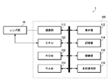
- FIG. 1 is a diagram showing a schematic configuration of an image pickup apparatus according to the present embodiment.
- the image pickup apparatus 1 of the present embodiment has a lens unit 10 and a main body unit 100.
- the lens unit 10 may be integrated with the main body unit 100, or may be detachable (replaceable).
- FIG. 2 is a diagram showing a schematic configuration of a lens portion.
- the lens unit 10 includes an image pickup optical system 20, a lens drive unit 30, a lens operation unit 40, and the like.
- the image pickup optical system 20 is composed of a zoom optical system, and has a zoom lens 22, an aperture 24, and a focus lens 26.
- an ND filter (ND: Neutral Density), which is a neutral density filter or a kind of neutral density filter, may be provided in place of the diaphragm 24 or in addition to the diaphragm 24.
- the zoom lens 22 and the focus lens 26 are composed of at least one lens.
- the lens drive unit 30 includes a zoom drive unit 32, an aperture drive unit 34, and a focus drive unit 36.
- the zoom drive unit 32 is a drive unit of the zoom lens 22.
- the zoom drive unit 32 includes an actuator (not shown) that drives the zoom lens 22, a drive circuit (not shown) for the actuator, and a sensor (not shown) that detects the position of the zoom lens 22.
- the actuator for example, a DC motor, a linear motor, a stepping motor, an ultrasonic motor, or the like is used.
- the zoom lens 22 is driven by the zoom drive unit 32 and moves back and forth along the optical axis L. As a result, the focal length (angle of view) changes.
- the aperture drive unit 34 is a drive unit of the aperture 24.
- the aperture drive unit 34 includes an actuator (not shown) for driving the aperture 24 and a drive circuit (not shown) for the actuator.
- the actuator for example, a DC motor, a linear motor, a stepping motor, an ultrasonic motor, or the like is used.
- the diaphragm 24 is driven by the diaphragm drive unit 34, and its opening diameter changes. As a result, the amount of light passing through the imaging optical system 20 changes.
- the focus drive unit 36 is a drive unit of the focus lens 26.
- the focus drive unit 36 includes an actuator (not shown) for driving the focus lens 26, a drive circuit for the actuator (not shown), and a sensor (not shown) for detecting the position of the focus lens 26.
- the actuator for example, a DC motor, a linear motor, a stepping motor, an ultrasonic motor, or the like is used.
- the focus lens 26 is driven by the focus drive unit 36 and moves back and forth along the optical axis L. As a result, the focus position changes.
- the lens operation unit 40 has a zoom operation unit 42, an aperture operation unit 44, and a focus operation unit 46.
- the zoom operation unit 42 has a zoom ring (not shown) as an operation member and a sensor (not shown) for detecting the position of the zoom ring.
- the zoom ring is rotatably provided on the outer circumference of the lens barrel.
- the information on the position of the zoom ring detected by the sensor is output to the CPU 120.
- the CPU 120 controls the driving of the zoom lens 22 based on the acquired information on the position of the zoom ring.
- the zoom ring is used to operate the zoom, but the zoom operation may be performed by a lever operation, a knob operation, or the like.
- the aperture operation unit 44 has an aperture ring (not shown) as an operation member and a sensor (not shown) for detecting the position of the aperture ring.
- the aperture ring is rotatably provided on the outer circumference of the lens barrel.
- the information on the position of the aperture ring detected by the sensor is output to the CPU 120.
- the CPU 120 controls the drive of the aperture 24 based on the acquired information on the position of the aperture ring.
- the focus operation unit 46 is a focus operation unit.
- the focus operation unit 46 has a focus ring (not shown) as an operation member and a sensor (not shown) for detecting the position of the focus ring.
- the focus ring is rotatably provided on the outer circumference of the lens barrel.
- the information on the position of the focus ring detected by the sensor is output to the CPU 120.
- the CPU 120 controls the drive of the focus lens 26 based on the acquired information on the position of the focus ring.
- the MF mode is an operation mode in which the focus is adjusted manually.
- the focus adjustment operation mode (focus mode) includes an MF mode and an AF mode, which are selected by the user.
- the AF mode is an operation mode in which the focus is automatically adjusted.
- the focus mode is selected by the main body operation unit 118.
- the focus can be operated by lever operation, knob operation, or the like.
- the main body 100 includes an image pickup unit 110, a display unit 112, a storage unit 114, a connection unit 116, a main unit operation unit 118, a CPU (Central Processing Unit) 120, a ROM (ReadOnlyMemory) 122, and It has a RAM (RandomAccessMemory) 124 and the like.
- the image pickup unit 110 includes an image pickup element 110A that converts an optical image into an electric signal (see FIG. 2).
- an image pickup element 110A for example, a CMOS image sensor (CMOS: Complementary Metal Oxide Semiconductor) having a predetermined color filter array (for example, a bayer array or the like), a CCD image sensor (CCD: Charged Coupled Device), or the like is used.
- CMOS Complementary Metal Oxide Semiconductor
- CCD image sensor Charged Coupled Device
- the image pickup element 110A a CMOS image sensor including a drive unit, an ADC (Analog to Digital Converter), a signal processing unit, and the like is used.
- the image sensor 110A is driven by the built-in drive unit to operate.
- the signal of each pixel is converted into a digital signal by the built-in ADC and output.
- the signal of each pixel is output after being subjected to signal processing such as correlation double sampling processing, gain processing, and correction processing by the built-in signal processing unit.
- the signal processing may be performed on the signal before being converted into a digital signal, or may be performed on the signal after being converted into a digital signal.
- the image pickup element 110A in which the phase difference detection pixel is incorporated is used as the image pickup element 110A.
- the image sensor 110A incorporating the phase difference detection pixel it is possible to acquire information on the phase difference of the subject in the screen.
- the direction of the focus of the subject in the screen and the amount of the focus (defocus amount) can be detected from the acquired phase difference information. Since the image sensor 110A incorporating the phase difference detection pixel and the phase difference detection method using the image sensor 110A are known techniques, the details thereof will be omitted.
- Imaging of moving images is performed at a predetermined frame rate.
- the frame rate may be fixed or may be arbitrarily set by the user.
- the display unit 112 is composed of a display such as an LCD (Liquid Crystal Display) and an organic EL display (Organic Light Emitting Diode display, OLED Display).
- the display unit 112 can also be configured with a touch panel display having a touch panel on its display surface.
- the display unit 112 also includes a form of an EVF (Electronic ViewFinder).
- the display unit 112 is used not only for displaying the live view, but also as a GUI (Graphical User Interface) for making various settings.
- GUI Graphic User Interface
- the storage unit 114 is used as a storage area for captured moving image data and also as a storage area for various data.
- the storage unit 114 is, for example, a semiconductor memory having non-volatile properties such as EEPROM (Electrically Erasable Programmable Read-Only Memory) including a flash memory, or an SSD (Solid State Drive) containing these semiconductor memories. It is composed.
- the storage unit 114 may have a configuration integrally provided in the main body of the device (a form of a so-called built-in memory) or a configuration in which the storage unit 114 can be attached to and detached from the main body of the device (a form of a so-called memory card). Further, it may be in a form of being connected so as to be able to communicate by wire or wirelessly. Further, when an external storage device is connected to the connection unit 116 described later, the external storage device also functions as the storage unit 114.
- connection unit 116 is used for connecting an external device (for example, an external display device, an external storage device, etc.).
- the connection portion 116 includes at least one terminal.
- a connection standard for example, HDMI (High-Definition Multimedia Interface) or the like can be adopted (HDMI is a registered trademark).
- the main body operation unit 118 includes various operation members for operating the image pickup device 1.
- the operation member includes various operation buttons such as a power button for instructing on and off of the power supply and a recording button for instructing the start and end of recording.
- the display unit 112 is composed of a touch panel display, the touch panel is also included in the main body operation unit 118.
- the focus mode is selected by the main unit operation unit 118.
- the main body operation unit 118 is provided with a focus mode changeover switch as a means for selecting a focus mode.
- the focus mode changeover switch selectively switches between the MF mode and the AF mode.
- the focus mode can be selected (set) by using a setting screen or the like.
- the CPU 120 is an example of a processor.
- the CPU 120 functions as a control unit, an image processing unit, and the like of the image pickup apparatus 1 by executing a predetermined program (imaging control program).
- the control performed by the CPU 120 includes display control, recording control, etc. in addition to imaging control.
- the image pickup control includes drive control of the lens unit 10 and the image pickup unit 110, as well as detection, detection, and calculation processing of information necessary for control.
- the detection, detection and calculation processing of information necessary for control includes, for example, detection or calculation processing of brightness necessary for exposure control, detection or calculation processing of focus evaluation value necessary for AF control, and the like.
- tracking processing is also included. Tracking AF is one of the AF functions, and is a function that automatically tracks and keeps focusing even if the subject moves. In the tracking AF, as the tracking process, a process of setting the focus area according to the movement of the subject to be tracked is performed.
- the subject focused by the MF is set as the tracking target, and the tracking AF is automatically started. Tracking AF is continuously performed until the focus operation is performed again. This process will be described in more detail later.
- the MF mode is an example of the first focus mode.
- the image processing performed by the CPU 120 includes not only the generation processing of moving image data for recording and display (for live view), but also the compression processing for the moving image data for recording.
- the moving image data for recording and display is generated by performing predetermined image processing (so-called development processing) on the RAW data (raw moving image data output from the imaging unit 110).
- the image processing here includes offset processing, gamma correction processing, demosaic processing, RGB / YCrCb conversion processing, white balance processing, and the like. Since these processes are known processes, the details thereof will be omitted.
- the compression process is a process of generating a moving image file in a predetermined compression format.
- a known codec can be adopted as the codec for compression. For example, a codec (MPEG-1, MPEG-2, MPEG-4, etc.) standardized by MPEG (Moving Picture Experts Group) can be adopted.
- each of the above processes performed by the CPU 120 may be partially or entirely performed by hardware provided inside the CPU 120.
- the ROM 122 stores a program executed by the CPU 120 and various data necessary for control and the like.
- the memory constituting the ROM 122 includes an EEPROM including a flash memory.
- the RAM 124 is used as a work area or the like when the CPU 120 performs various processes.
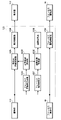
- FIG. 3 and 4 are block diagrams of functions realized by the CPU in the MF mode.
- FIG. 3 is a block diagram of a function mainly realized when the focus operation is manually performed. That is, it is a block diagram of a function realized in a normal MF mode.
- FIG. 4 is a block diagram of a function mainly realized when tracking AF is performed.
- the CPU 120 in the MF mode, includes a display image processing unit 120A, a display control unit 120B, a focus evaluation value calculation unit 120C, a focus area detection unit 120D, a tracking target setting unit 120E, and a focus. It functions as an operation detection unit 120F, a focus drive control unit 120G, a tracking processing unit 120H, an AF control unit 120I, and the like.
- the display image processing unit 120A processes the moving image data (RAW data) output from the imaging unit 110 to generate the moving image data for display.
- RAW data moving image data
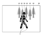
- FIG. 5 is a diagram showing one frame of a moving image displayed on the display unit during the focus operation.
- the figure shows an example of an image displayed on the display unit 112 when the person 300 in the foreground is focused and imaged.
- the background tree 400 is blurred and imaged.
- the image IM1 displayed during the focus operation is given information indicating the in-focus area.
- the frame F1 of the focus area in the in-focus state is displayed as the information indicating the in-focus area. More specifically, the frame F1 of the focus area in the focused state is superimposed and displayed on the image of the live view.
- the frame F1 is displayed in a predetermined color. In this embodiment, the frame F1 of the focus area in the focused state is displayed in red. The focus area will be described later.
- the display image processing unit 120A generates moving image data for display based on the information of the in-focus area detected by the in-focus area detection unit 120D during the focus operation. The detection of the in-focus region will be described later.
- FIG. 6 is a diagram showing one frame of a moving image displayed on the display unit during tracking AF. The figure shows an example of an image displayed on the display unit 112 when the person 300 in the foreground is targeted for tracking.
- Tracking AF keeps focusing on the subject set as the tracking target.
- the frame F2 of the focus area in which the subject to be tracked exists is displayed in a predetermined color. This color is different from the color (red) of the frame F1 indicating the in-focus area during the focus operation. In this embodiment, it is displayed in green.
- a frame indicating the tracking target is displayed in a color different from that during the focus operation.
- the tracking target can be recognized from the image displayed on the display unit 112, and at the same time, it can be recognized that the tracking AF is in progress. Since the focus is continuously focused on the tracking target during the tracking AF, the focus area in which the subject to be tracked exists is substantially the focusing area. Therefore, the frame F2 of the focus area in which the subject to be tracked exists is also information indicating the in-focus area.
- the display image processing unit 120A generates moving image data for display based on the information of the focus target area set by the tracking processing unit 120H during the tracking AF.
- the focus target area will be described later.
- the display control unit 120B causes the display unit 112 to display the moving image data for display generated by the display image processing unit 120A.
- the display unit 112 is an example of a display destination.
- the display of the display unit 112 may be configured to be turned off. Further, it may be configured to display other information.
- the focus evaluation value calculation unit 120C calculates the focus evaluation value of the preset focus area based on the moving image data captured by the image pickup unit 110.
- FIG. 7 is a diagram showing an example of setting the focus area.
- the focus area FA is set by equally dividing the screen in the vertical direction and the horizontal direction.
- the screen is divided into 9 equal parts in the vertical direction (y direction) and 13 equal parts in the horizontal direction (x direction), and 9 ⁇ 13 focus area FAs are set.
- the focus evaluation value calculation unit 120C calculates the focus evaluation value of each focus area FA.
- the focus evaluation value is an index showing the focus state.
- the defocus amount obtained from the phase difference information or the phase difference information is calculated as the focus evaluation value.
- the phase difference information is calculated based on the information of the phase difference detection pixel of each focus area FA. Since this is a known technique, the details thereof will be omitted.
- the in-focus area detection unit 120D detects the in-focus area based on the information of the focus evaluation value of each focus area FA calculated by the focus evaluation value calculation unit 120C. That is, the in-focus area is detected.
- the focused area in focus is selected as the in-focus area.
- the in-focus focus area is a focus area in which the phase difference or the defocus amount is equal to or less than the allowable value.
- the tracking target setting unit 120E sets the subject to be tracked.
- the tracking target setting unit 120E sets the tracking target in response to the detection of the end of the focus operation. That is, when the end of the focus operation is detected by the focus operation detection unit 120F, the tracking target is set.
- the tracking target setting unit 120E sets the subject existing in the focusing region as the tracking target when the end of the focus operation is detected. For example, when the end of the focus operation is detected in the state shown in FIG. 5, the person 300 is set as the tracking target.
- the focus operation detection unit 120F detects the start and end of the focus operation.
- the start of the focus operation is detected by the change in the position of the focus ring. That is, the start of the change in the position of the focus ring is detected, and the start of the operation is detected. As described above, the position of the focus ring is detected by the sensor provided in the focus operation unit 46. Therefore, the focus operation detection unit 120F detects the start of the focus operation based on the output of the sensor.
- the end of the focus operation is detected based on the time related to the focus operation. Specifically, the end of the focus operation is detected based on the time in the non-operation state.
- the no-operation state means a state in which there is no focus operation.
- the focus is operated by the focus ring. Therefore, the state without focus operation means the state without operation of the focus ring.
- the state in which the focus ring is not operated is a state in which the position of the focus ring does not change.
- the focus operation detection unit 120F measures the duration of the non-operation state (the state where the position of the focus ring does not change) based on the output of the sensor that detects the position of the focus ring. Then, it is detected that the specified time has elapsed from the start of the no-operation state, and the end of the focus operation is detected.
- the specified time is an example of the first time.
- the specified time is, for example, 500 ms. In this case, the focus operation detection unit 120F detects that 500 ms has elapsed from the start of the non-operation state, and detects the end of the focus operation.
- the focus drive control unit 120G controls the drive of the focus lens 26 via the focus drive unit 36.
- the focus drive control unit 120G controls the drive of the focus lens 26 based on the focus ring operation information (focus ring position information) from the focus operation unit 46.
- the drive of the focus lens 26 is controlled based on the control information from the AF control unit 120I.
- the tracking processing unit 120H performs tracking processing.
- the tracking process includes a process of detecting a tracking target and a process of setting a focus target area based on the detection result.
- the process of detecting the tracking target is performed based on the moving image data output from the image pickup unit 110. Specifically, the tracking target is sequentially detected from the image of each frame constituting the moving image data. A known method such as template matching is adopted for the detection.
- the focus target area is the area to focus on.
- the focus target area is set from the focus area.
- the tracking processing unit 120H sets the focus area in which the tracking target exists as the focus target area. Since the tracking target is sequentially detected for each frame, the focus target area is also sequentially set for each frame.
- the tracking processing unit 120H continuously performs tracking processing until the focus operation is started again or until the tracking target disappears. Therefore, even if the tracking target exists, if the focus operation is performed again, the tracking process is forcibly terminated.
- the AF control unit 120I performs AF control (autofocus control) on the focus target area set by the tracking processing unit 120H. That is, control is performed to focus on the subject in the set focus target area. Specifically, first, the control amount of the focus lens 26 (drive amount of the focus drive unit 36) required to focus on the subject in the focus target area is calculated based on the information of the focus evaluation value in the focus target area. do. Then, the calculated control amount information is given to the focus drive control unit 120G. The focus drive control unit 120G drives the focus drive unit 36 based on the information of the given control amount.
- AF control autofocus control
- the AF control unit 120I continuously performs AF control until the focus operation is restarted or the tracking target disappears.
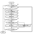
- FIG. 8 is a flowchart showing a processing procedure of image pickup control performed in the MF mode.
- step S1 it is determined whether or not the focus operation has been started. Whether or not there is a focus operation is determined based on the output from the focus operation unit 46. That is, the determination is made based on the output from the sensor that detects the position of the focus ring. If there is an output from the sensor that detects the position of the focus ring, it is determined that the focus operation has started.
- step S2 it is determined whether or not the focus mode is set to the MF mode.
- the focus mode is determined based on the setting state of the focus mode changeover switch.
- the focus evaluation value of each focus area is calculated (step S3).
- the in-focus region is detected (step S4). That is, the focus area in the focused state is detected.
- the detected in-focus area is shown on the live view image.
- the frame of the focus area determined to be the in-focus area is displayed in red. Therefore, the user (cameraman) can confirm the in-focus area by visually recognizing the live view.
- the tracking target is set (step S5).
- the tracking target is set to a subject existing in the in-focus area.
- the in-focus area is set as the area to be tracked. That is, the in-focus area is set as the area where the tracking target exists.
- step S6 After setting the tracking target, it is determined whether or not the focus operation is completed (step S6).
- the focus operation is determined to be the end of the operation when the non-operation state continues for a specified time. That is, the end of operation is detected.
- tracking AF is started (step S7). That is, the tracking process and the AF control are continuously performed on the subject set as the tracking target. More specifically, the focus target area is set according to the movement of the subject set as the tracking target, and AF control (so-called continuous AF control) is continuously performed so that the subject in the set focus target area is in focus. ) Is performed.
- the display of the in-focus area is switched. That is, the color of the frame of the focus area indicating the in-focus area is switched. In the present embodiment, the color of the frame of the focus area indicating the in-focus area is switched from red to green. As a result, the user can recognize that the mode has shifted to the tracking AF mode. At the same time, the subject set as the tracking target can be recognized.
- Tracking AF is continuously performed until the focus operation is restarted or until the tracking target disappears. Therefore, the focus operation is always monitored during the tracking AF. That is, it is determined whether or not the focus operation has been performed again (step S8). When it is determined that the focus operation has been restarted, the tracking AF is forcibly terminated. That is, the tracking process and the AF control based on the tracking process are terminated. After the tracking AF is completed, the operation returns to the normal MF mode operation, and the processing after step S2 is repeated.
- FIG. 9 is a diagram showing an example of a live view display in the MF mode.
- FIG. (A) shows an example of a display during a focus operation.
- FIG. (B) shows an example of the display immediately after the end of the focus operation is detected.
- FIG. 3C shows an example of the display during tracking AF.
- the frame F1 of the focus area in the in-focus state is displayed in red as information indicating the in-focus area.
- FIG. 9A shows that the background tree is in focus.
- FIG. 9B shows that the focus operation is completed by focusing on the person in front.
- the frame F2 of the focus area where the tracking target exists is displayed in green. As a result, the tracking target can be confirmed on the screen.
- tracking AF ends.
- the operation returns to the normal MF mode operation. Therefore, the display of the display unit 112 returns to the state of FIG. 9A. That is, the frame F1 of the focus area in the focused state is displayed in red. By switching the color of the displayed frame F1 from green to red, it can be confirmed that the normal MF mode has been restored.
- the display unit 112 may display information notifying the end of the tracking AF.
- the image pickup device 1 maintains the focusing by the MF. Therefore, the burden of the focus operation by the user can be significantly reduced.
- the start of tracking AF is determined based on the time related to the focus operation, particularly the duration of the non-operation state. Therefore, the tracking AF can be started according to the user's intention. Moreover, since a special mechanism for switching is not required, the configuration can be simplified.
- the tracking AF when the tracking AF is switched, the display content of the display unit 112 is switched, so that the operating state can be clearly grasped. Thereby, good operability can be realized.
- the end of the focus operation is detected based on the time related to the focus operation.
- the time related to the focus operation is preferably the time in the non-operation state. That is, it is preferable to detect the end of the focus operation based on the duration of the non-operation state.
- 0 can be included in the duration of the non-operation state (hereinafter referred to as the detection time) for detecting the end of the focus operation.
- the detection time first time
- tracking AF is started immediately after the focus ring is stopped.
- the detection time may be arbitrarily set by the user. This setting is performed using, for example, the display unit 112 and the main body operation unit 118. This makes it possible to make settings according to the user's preference and the like.
- the detection time may be automatically set based on the user's past operation tendency. For example, the duration of the non-operation state may be recorded for a plurality of times, and a preferable detection time may be calculated and set by a statistical method.
- FIG. 10 is a block diagram showing an example of a function realized by the CPU when the detection time is set by using a statistical method.
- the CPU 120 further functions as a first timekeeping unit 130A, a measurement result recording control unit 130B, a detection time calculation unit 130C, a detection time setting unit 130D, and the like.
- the first timekeeping unit 130A measures the duration of the non-operation state.
- the measurement result recording control unit 130B records the information of the measurement result of the duration of the non-operation state by the first timekeeping unit 130A.
- the measurement result is stored in the measurement result storage unit 114A.
- the measurement result storage unit 114A is set in one storage area of the storage unit 114.
- the measurement result storage unit 114A stores the measurement results for a predetermined number of times. As an example, in this example, the measurement results for three times are stored.
- the measurement result recording control unit 130B rewrites the measurement results in chronological order and records the measurement results. Therefore, the measurement result storage unit 114A stores the measurement results for the most recent specified number of times (three times in this example).
- the detection time calculation unit 130C calculates the detection time by a statistical method based on the information of the duration of the non-operation state for a plurality of times stored in the measurement result storage unit 114A. In this example, the average value is calculated to calculate the detection time.
- the detection time setting unit 130D sets the time calculated by the detection time calculation unit 130C as the detection time.
- the focus operation detection unit 120F detects the end of the focus operation based on the detection time set by the detection time setting unit 130D.
- the detection time can be automatically set based on the user's past operation tendency. As a result, it is possible to switch to tracking AF according to the user's operation tendency.
- An upper limit may be set for the detection time that can be set. As a result, it is possible to prevent the detection time from being unintentionally set long. In this case, it is more preferable to be able to arbitrarily set the upper limit value.
- the method of calculating the average value is configured as a statistical method, but the method of calculating the detection time is not limited to this.
- the median value, the mode value, and the like can be calculated as the detection time.
- the tracking target can be set only for a specific subject by using image recognition. For example, in imaging a person, the tracking target can be set only for the person existing in the in-focus area. It is also possible to set the tracking target not for the entire person but for the face, eyes, and the like.
- FIG. 11 is a block diagram showing an example of a function realized by the CPU when setting a tracking target using image recognition.
- a case where the tracking target is set only for the face will be described as an example.
- the CPU 120 further functions as an image recognition unit 140.
- the image recognition unit 140 processes the moving image data captured by the image pickup unit 110 and detects a face in the image.
- a known technique can be adopted as a technique for detecting a face from an image.
- the tracking target setting unit 120E sets the tracking target based on the information of the focusing area detected by the focusing area detection unit 120D and the information of the face area of the person detected by the image recognition unit 140. Specifically, the tracking target is set in the area of the face of a person among the subjects existing in the in-focus area. Therefore, in this case, even if the entire body of the person is in focus, the tracking target is limited to the face area and the tracking target is set.
- the frame of the focus area in the in-focus state is displayed as the information indicating the in-focus area, but the display form of the information indicating the in-focus area (a form added to the image of the live view). Is not limited to this. Any form may be used as long as the in-focus area can be visually recognized on the live view image.
- FIG. 12 is a diagram showing another example of the display form of the information indicating the in-focus area.
- the in-focus area is displayed by one rectangular frame F3.
- This frame F3 is set, for example, as the minimum frame surrounding the focus area in the focused state.
- the switching of the operation mode can be recognized by changing the color of the frame, but the method of making the user recognize the switching of the operation mode is not limited to this.
- the user can be made aware of the switching of the operation mode.
- the shape of the frame indicating the in-focus area, the line type, and the like may be changed to recognize the change of the operation mode.
- the tracking AF when the end of the focus operation is detected in the MF mode, the tracking AF is automatically started, but the function may be arbitrarily turned on and off by the user's setting. That is, only when the function is turned on, the tracking AF is automatically started when the end of the focus operation is detected in the MF mode.
- the setting is performed, for example, by providing a dedicated changeover switch or the like on the main body operation unit 118. Alternatively, the display unit 112 and the main body operation unit 118 are used.
- the operation mode in which the tracking AF is performed that is, the operation mode when the tracking AF function is set to ON is another example of the first focus mode.
- the focus movement direction is limited to a certain direction for a certain period of time. That is, the movement direction of the focus by AF is limited to the same direction as the movement direction of the focus when the focus operation is completed. Therefore, for example, when the focus is moved from the closest side to the infinity side to focus on the target subject, the movement direction of the focus by AF is limited to the infinity direction for a specified time. As a result, stable focus movement can be realized in the imaging of moving images.
- FIG. 13 is a block diagram of the main functions realized by the CPU when the tracking AF is performed by limiting the moving direction of the focus.
- the CPU 120 further functions as a focus movement direction detection unit 150A and a second timekeeping unit 150B.
- the focus movement direction detection unit 150A detects the focus movement direction based on the operation information of the focus ring output from the focus operation unit 46. In the MF, the focus moves in the operating direction of the focus ring. Therefore, by detecting the operation direction of the focus ring, the moving direction of the focus can be detected.
- the second timing unit 150B measures the elapsed time since the start of tracking AF.
- the tracking AF is started in response to the detection of the end of the focus operation. Therefore, the second timing unit 150B starts measuring the elapsed time in response to the detection of the end of the focus operation.
- the AF control unit 120I limits the movement direction of the focus to the movement direction of the immediately preceding focus until a certain time elapses after the start of the AF control, and performs AF control.
- the moving direction of the focus immediately before is the moving direction of the focus immediately before the end of the focus operation is detected.
- the movement direction of the focus immediately before is detected as the movement direction of the focus finally detected by the focus movement direction detection unit 150A when the end of the focus operation is detected.
- the elapsed time from the start of tracking AF is measured by the second timing unit 150B. Therefore, the AF control unit 120I limits the movement direction of the focus to the immediately preceding movement direction until the time measured by the second timing unit 150B elapses, and performs AF control.
- the specified time is an example of the second time.
- the specified time is set to 3s.
- the focus movement direction is limited to the immediately preceding movement direction for 3 seconds. Since the tracking AF is started in response to the detection of the end of the focus operation, the elapsed time from the start of the tracking AF is synonymous with the elapsed time after the end of the focus operation is detected.
- FIG. 14 is a flowchart showing a processing procedure of image pickup control.
- step S11 it is determined whether or not the focus operation has been started (step S11).
- the focus operation it is determined whether or not the focus mode is set to the MF mode (step S12).
- the focus evaluation value of each focus area is calculated (step S13), and the focusing region is detected based on the calculation result (step S14).
- the tracking target is set based on the information of the detected focusing region (step S15). That is, the subject existing in the in-focus area is set as the tracking target.
- step S16 it is determined whether or not the focus operation is completed (step S16).
- step S17 it is determined whether or not the specified time (second time) has elapsed. That is, it is determined whether or not a specified time has elapsed from the setting of the tracking target.
- step S18 tracking AF that limits the focus movement direction is performed (step S18).
- the AF control unit 120I limits the moving direction of the focus to the moving direction of the focus immediately before the end of the focus operation is detected, and performs AF control. For example, when the focus is moved from the closest side to the infinity side to end the focus operation, the AF control is performed by limiting the movement direction of the focus to the infinity direction. Therefore, for example, if the tracking target moves in the closest direction during this period, AF control will not be performed.
- step S19 normal tracking AF is performed (step S19). That is, AF control is performed without limiting the moving direction of the focus.
- Tracking AF is continuously performed until the focus operation is restarted or until the tracking target disappears. Therefore, the focus operation is always monitored during the tracking AF. That is, it is determined whether or not the focus operation has been performed again (step S20). When it is determined that the focus operation has been restarted, the tracking AF is forcibly terminated. After the end of the tracking AF, the operation returns to the normal MF mode, and the processing after step S12 is repeated.
- the moving direction of the focus is limited to a certain direction for a certain period of time. As a result, stable focus movement can be realized in the imaging of moving images.
- this function may be turned on and off arbitrarily by the user's choice. Further, the user may arbitrarily change the setting for the specified time.
- the tracking AF is forcibly terminated and the operation is switched to the normal MF mode.
- stable focus movement can be realized in the imaging of moving images.
- FIG. 15 is a block diagram of the main functions realized by the CPU when the tracking AF is forcibly terminated when the posture of the image pickup device changes.
- the CPU 120 further functions as a posture change detection unit 160.
- the image pickup device of the present embodiment is provided with a posture detection sensor 50 that detects the posture of the main body of the device.
- the attitude detection sensor 50 is composed of a known attitude detection sensor (for example, an acceleration sensor, a gyro sensor, or a sensor in which these are combined), and is built in the main body of the apparatus.
- the posture change detection unit 160 detects a change in posture equal to or higher than the threshold value with respect to the reference posture based on the posture information of the main body of the device detected by the posture detection sensor 50.
- a change in posture around the optical axis is detected.
- the reference posture is, for example, a posture in which the long side of the image sensor 110A is horizontal or vertical.
- the posture in which the long side of the image sensor 110A is horizontal is the so-called horizontal shooting posture.
- the posture in which the long side of the image sensor 110A is vertical is the so-called vertical shooting posture.
- the user sets the reference posture in advance.
- the posture when the moving image is captured is set to the reference posture. In this case, the posture of the main body of the device is detected when the moving image is captured, and the posture is set to the reference posture.
- the tracking processing unit 120H ends the tracking processing when the posture change detecting unit 160 detects a change in posture equal to or higher than the threshold value during the tracking processing.
- the AF control unit 120I ends the AF control when the attitude change detection unit 160 detects a change in attitude equal to or greater than the threshold value during AF control.
- FIG. 16 is a flowchart showing a processing procedure of image pickup control.
- step S31 it is determined whether or not the focus operation has been started.
- step S32 it is determined whether or not the focus mode is set to the MF mode.
- step S33 the focus evaluation value of each focus area is calculated (step S33), and the focusing region is detected based on the calculation result (step S34).
- step S35 the tracking target is set based on the information of the detected focusing region (step S35). That is, the subject existing in the in-focus area is set as the tracking target.
- step S36 it is determined whether or not the focus operation is completed.
- step S37 the tracking process and the AF control are performed on the subject set as the tracking target.
- step S38 it is first determined whether or not the focus operation has been performed again.
- the tracking AF is forcibly terminated. After that, the operation returns to the normal MF mode, and the processing after step S32 is repeated.
- step S38 if it is determined in step S38 that the focus operation has not been restarted, the posture of the apparatus main body is detected (step S39). Then, based on the detection result, the presence or absence of a change in posture is determined (step S40). That is, it is determined whether or not the posture has changed by the threshold value or more with respect to the reference posture.
- tracking AF will be forcibly terminated. After that, the operation returns to the normal MF mode, and the processing after step S32 is repeated.
- step S37 the processes after step S37 are repeated.
- the tracking AF is automatically terminated and the operation is switched to the normal MF mode. As a result, stable focus movement can be realized in the imaging of moving images.
- this function may be turned on and off arbitrarily by the user's choice.
- the threshold value used for detecting the posture change may be configured so that the user can arbitrarily change the setting.
- the type of posture to be detected may be configured to be arbitrarily set by the user.
- the configuration is such that the change in the posture of the device main body is detected by using a dedicated sensor, but the configuration is such that the change in the posture of the device main body is detected by analyzing the captured moving image data. May be good.
- a sensor for detecting camera shake may be used to detect a change in the posture of the main body of the device.
- FIG. 17 is a block diagram of the main functions realized by the CPU when performing tracking AF.
- the CPU 120 further functions as the first movement amount calculation unit 170.
- the first movement amount calculation unit 170 processes the moving image data obtained by imaging, and calculates the movement amount of the subject in the image represented by the moving image data.
- a motion vector is calculated as the motion amount. That is, the first motion amount calculation unit 170 calculates the motion vector in the image and calculates the motion vector of the subject in the image.
- a known technique is adopted for the calculation of the motion vector. For example, a method of dividing the screen into blocks of M ⁇ N (M and N are integers of 2 or more) and calculating a motion vector for each block is adopted.
- the tracking processing unit 120H sets the tracking target based on the information of the movement amount of each subject calculated by the first movement amount calculation unit 170, and performs the tracking processing. conduct. Specifically, a subject with no movement or a subject with the smallest amount of movement is preferentially set as a tracking target, and tracking processing is performed. Therefore, when a plurality of subjects are set as tracking targets, the tracking processing unit 120H performs a process of excluding subjects having a movement amount equal to or greater than a threshold value from the tracking targets. As a result, the subject with no movement or the subject with the smallest amount of movement is finally set as the tracking target, and the tracking process is performed.
- FIG. 18 is a flowchart showing a processing procedure of image pickup control.
- step S51 it is determined whether or not the focus operation has been started.
- step S52 it is determined whether or not the focus mode is set to the MF mode.
- step S53 the focus evaluation value of each focus area is calculated (step S53), and the focusing region is detected based on the calculation result (step S54).
- step S55 the tracking target is set based on the information of the detected focusing region (step S55). That is, the subject existing in the in-focus area is set as the tracking target.
- step S56 it is determined whether or not the focus operation is completed.
- step S57 it is determined whether or not a plurality of subjects are set as tracking targets. If it is determined that a plurality of subjects are not set as the tracking target, tracking AF is performed on the subject set as the tracking target (step S61).
- step S58 the amount of movement of each subject in the image is calculated. Then, based on the calculation result, the presence or absence of a moving subject is determined (step S59). The determination here is performed in the subject set as the tracking target. That is, it is determined whether or not there is a moving subject (moving object) among the subjects set as the tracking target.
- step S60 If it is determined that there is a moving subject among the subjects set as the tracking target, that subject is excluded from the tracking target (step S60).
- the subject in which the amount of movement equal to or greater than the threshold value is detected is excluded from the tracking target.
- the subject with a large amount of movement is preferentially excluded. At this time, they are excluded in descending order of the amount of movement. As a result, the subject with the smallest amount of movement is set as the tracking target.
- step S61 tracking AF is performed on the subject set as the tracking target (step S61). Then, it is determined whether or not the focus operation has been performed again (step S62), and when it is determined that the focus operation has been restarted, the tracking AF is terminated. After that, the operation returns to the normal MF mode, and the processing after step S52 is repeated.
- FIG. 19 is a conceptual diagram of the setting of the tracking target.
- the figure (A) shows the initial setting state of the tracking target.
- an example is shown in which three people 300A, 300B, and 300C are present in the in-focus area when the end of the focus operation is detected. In this case, all the persons 300A, 300B, and 300C are set as tracking targets.
- the figure (B) shows the setting state of the tracking target after the lapse of a predetermined time.
- This example shows an example when the left and right persons 300A and 300C move. In this case, the moving left and right persons 300A and 300C are excluded from the tracking target. Therefore, only the central person 300B is selected as the tracking target.
- the tracking targets are set based on the amount of movement of each subject thereafter, and the tracking AF is performed. Will be done. This makes it possible to continuously focus on the subject intended by the user. Further, this can reduce the load of the user's focus adjustment. In addition, stable focus movement can be realized.
- the tracking target is determined by using the phase difference information, and tracking AF is performed.
- the phase difference information is used to calculate the amount of movement of each subject in the optical axis direction, the subject with the smallest amount of movement in the optical axis direction is preferentially set as the tracking target, and tracking AF is performed. ..
- the optical axis direction is a direction along the optical axis of the imaging optical system 20. In the image pickup apparatus of this embodiment, the optical axis direction of the image pickup optical system 20 coincides with the direction orthogonal to the light receiving surface of the image pickup element.
- FIG. 20 is a block diagram of the main functions realized by the CPU when performing tracking AF.
- the CPU 120 further functions as a second movement amount calculation unit 180.
- the second movement amount calculation unit 180 processes the moving image data obtained by imaging and calculates the movement amount of each subject in the optical axis direction. Specifically, the phase difference of each focus area is calculated based on the pixel signal of the pixel for phase difference detection, the amount of change thereof is calculated, and the amount of movement of each subject in the optical axis direction is calculated. Therefore, in the image pickup apparatus of this embodiment, the amount of change in the phase difference is the amount of movement in the optical axis direction.
- the tracking processing unit 120H sets the tracking target based on the information of the movement amount of each subject in the optical axis direction calculated by the second movement amount calculation unit 180. Perform tracking processing. Specifically, the tracking process is performed by excluding the subject moving in the optical axis direction from the tracking target.
- a subject that moves in the optical axis direction is a subject whose amount of movement in the optical axis direction is equal to or greater than a threshold value. If all subjects have movement in the optical axis direction, they are excluded in descending order of the amount of movement in the optical axis direction. As a result, the subject having the smallest amount of movement in the optical axis direction is set as the tracking target, and tracking AF is performed.
- FIG. 21 is a flowchart showing a processing procedure of image pickup control.
- step S71 it is determined whether or not the focus operation has been started.
- the focus operation it is determined whether or not the focus mode is set to the MF mode (step S72).
- the focus evaluation value of each focus area is calculated (step S73), and the focusing region is detected based on the calculation result (step S74).
- the tracking target is set based on the information of the detected focusing region (step S75). That is, the subject existing in the in-focus area is set as the tracking target.
- step S76 it is determined whether or not the focus operation is completed.
- step S77 it is determined whether or not a plurality of subjects are set as tracking targets. If it is determined that a plurality of subjects are not set as the tracking target, tracking AF is performed on the subject set as the tracking target (step S82).
- step S78 it is determined whether or not the amount of movement in the optical axis direction can be calculated.
- the amount of movement in the optical axis direction is calculated based on the phase difference. Therefore, if the phase difference cannot be calculated, the amount of movement in the optical axis direction cannot be calculated either. Therefore, when the phase difference cannot be calculated, it is determined that the amount of movement in the optical axis direction cannot be calculated. For example, if the subject exists in an area where the phase difference detection pixels are not arranged, it is determined that the phase difference cannot be calculated.
- step S84 When it is determined that the amount of movement in the optical axis direction cannot be calculated, the setting of the tracking target is canceled (step S84), and the process ends. After the processing is completed, it operates in the normal MF mode.
- step S79 the amount of movement in the optical axis direction of each subject is calculated. Then, based on the calculation result, the presence or absence of a subject moving in the optical axis direction is determined (step S80). The determination here is performed in the subject set as the tracking target. That is, it is determined whether or not there is a subject moving in the optical axis direction among the subjects set as the tracking target.
- step S81 If it is determined that there is a subject moving in the optical axis direction among the subjects set as the tracking target, that subject is excluded from the tracking target (step S81).
- step S82 After that, tracking AF is performed on the subject set as the tracking target (step S82). Then, it is determined whether or not the focus operation has been performed again (step S83), and when it is determined that the focus operation has been restarted, the tracking AF is terminated. After that, the operation returns to the normal MF mode, and the processing after step S52 is repeated.
- FIG. 22 is a conceptual diagram of the setting of the tracking target.
- the figure (A) shows the initial setting state of the tracking target.
- an example is shown in which three people 300A, 300B, and 300C are present in the in-focus area when the end of the focus operation is detected. In this case, all the persons 300A, 300B, and 300C are set as tracking targets.
- the figure (B) shows the setting state of the tracking target after the lapse of a predetermined time.
- an example is shown in which the left and right persons 300A and 300C move forward (front side in the depth direction). That is, an example is shown in the case where the image pickup optical system 20 moves in the optical axis direction. In this case, the left and right persons 300A and 300C moving in the optical axis direction are excluded from the tracking target. Therefore, only the central person 300B is selected as the tracking target.
- the tracking targets are set based on the amount of movement of each subject in the optical axis direction thereafter. , Tracking AF is performed. This makes it possible to continuously focus on the subject intended by the user. Further, this can reduce the load of the user's focus adjustment. In addition, stable focus movement can be realized.
- the amount of change in the phase difference is detected to detect the amount of movement of each subject in the optical axis direction.
- the method of detecting the amount of movement of each subject in the optical axis direction is It is not limited to this.
- it can be configured to detect by the ToF method (ToF: Time of Flight), Structured Light method, or the like.
- the phase difference is detected by using an image pickup device provided with a phase difference detection pixel, but the method for detecting the phase difference is not limited to this.
- step S78 can be omitted. For example, if the focus area is set in the entire area of the image and the phase difference can be detected in each focus area, the process of step S78 may be omitted.
- the image pickup apparatus of the present embodiment uses information on the amount of movement of each subject in the image and information on the amount of movement of each subject in the optical axis direction for tracking. Determine the target and perform tracking AF. Specifically, while the non-moving subject is preferentially set as the tracking target, when all the subjects have movement, the tracking target is determined based on the amount of movement in the optical axis direction, and tracking AF is performed. That is, the subject having the smallest amount of movement in the optical axis direction is preferentially set as the tracking target, and tracking AF is performed.
- FIG. 23 is a block diagram of the main functions realized by the CPU when performing tracking AF.
- the CPU 120 further functions as a first movement amount calculation unit 170 and a second movement amount calculation unit 180.
- the function of the first movement amount calculation unit 170 is the same as the function of the first movement amount calculation unit 170 provided in the image pickup apparatus of the fourth embodiment. That is, the moving image data obtained by imaging is processed, and the amount of movement (movement vector) of the subject in the image represented by the moving image data is calculated.
- the function of the second movement amount calculation unit 180 is the same as the function of the second movement amount calculation unit 180 provided in the image pickup apparatus of the fifth embodiment. That is, the moving image data obtained by imaging is processed, and the amount of movement (change amount of phase difference) in the optical axis direction of each subject is calculated.
- the tracking processing unit 120H sets the tracking target based on the calculation results of the first movement amount calculation unit 170 and the second movement amount calculation unit 180, and performs tracking processing. ..
- step S91 it is determined whether or not the focus operation has been started.
- step S92 it is determined whether or not the focus mode is set to the MF mode.
- step S93 the focus evaluation value of each focus area is calculated (step S93), and the focusing region is detected based on the calculation result (step S94).
- step S95 the tracking target is set based on the information of the detected focusing region (step S95). That is, the subject existing in the in-focus area is set as the tracking target.
- step S96 it is determined whether or not the focus operation is completed.
- step S97 it is determined whether or not a plurality of subjects are set as tracking targets. If it is determined that a plurality of subjects are not set as the tracking target, tracking AF is performed on the subject set as the tracking target (step S101).
- step S98 the amount of movement of each subject in the image is calculated. Then, based on the calculation result, it is determined whether or not all the subjects are moving objects (step S99). That is, it is determined whether or not all the subjects set as tracking targets are moving subjects.
- the moving subject is excluded from the tracking target (step S100). .. That is, the subject in which the amount of movement equal to or greater than the threshold value is detected is excluded from the tracking target.
- step S101 After that, tracking AF is performed on the subject set as the tracking target (step S101). Then, it is determined whether or not the focus operation has been performed again (step S102), and when it is determined that the focus operation has been restarted, the tracking AF is terminated. After that, the operation returns to the normal MF mode, and the processing after step S92 is repeated.
- step S99 if it is determined in step S99 that all the subjects set as tracking targets are moving objects, the flow shifts to the flow shown in FIG. 25. That is, it is determined whether or not the amount of movement in the optical axis direction can be calculated (step S103). Whether or not the amount of movement in the optical axis direction can be calculated is determined by whether or not the phase difference can be calculated for each subject. If there is a subject whose phase difference cannot be calculated, it is determined that the amount of movement in the optical axis direction cannot be calculated.
- step S106 When it is determined that the amount of movement in the optical axis direction cannot be calculated, the setting of the tracking target is canceled (step S106), and the process ends. After the processing is completed, it operates in the normal MF mode.
- step S104 the amount of movement in the optical axis direction of each subject is calculated. Then, based on the calculation result, the subjects moving in the optical axis direction are excluded from the tracking targets in descending order of the amount of movement (step S105). As a result, the subject having the smallest amount of movement in the optical axis direction is set as the tracking target.
- step S101 tracking AF is performed on the subject set as the tracking target (step S101). Then, it is determined whether or not the focus operation has been performed again (step S102), and when it is determined that the focus operation has been restarted, the tracking AF is terminated. After that, the operation returns to the normal MF mode, and the processing after step S92 is repeated.
- the tracking target is set based on the information on the amount of movement of each subject in the image and the information on the amount of movement of each subject in the optical axis direction. Tracking AF is performed. This makes it possible to continuously focus on the subject intended by the user. Further, this can reduce the load of the user's focus adjustment. In addition, stable focus can be achieved. That is, the focus can be adjusted as much as possible.
- the image pickup apparatus of this embodiment sets a tracking target based on the focus state of each subject during the focus operation. Specifically, if there is a subject that has changed from the focused state to the out-of-focus state during the focus operation and then returned to the focused state, the subject is set as the tracking target.
- the operation of returning to the in-focus state after changing from the in-focus state to the out-of-focus state is a so-called back-to-focus operation.
- the back-to-back operation is an operation to return the focus immediately after blurring during the focus operation. When the user performs the back-to-back operation, it is considered that the subject that is in focus due to the back-to-back operation is the main subject.
- the subject is set as the tracking target and tracking AF is performed. If there is no subject that has returned to the in-focus state after changing from the in-focus state to the out-of-focus state during the focus operation, the subject that has been in focus for the longest time during the focus operation is set as the tracking target. ..
- FIG. 26 is a block diagram of the main functions realized by the CPU when performing tracking AF.
- the CPU 120 further functions as a third timing unit 190 and a specific operation detection unit 192.
- the third timing unit 190 measures the period during which the focus is in focus (focus period) for each focus area during the focus operation.
- the third timing unit 190 measures the focusing period of each focus area based on the information of the focusing area detected in real time by the focusing area detecting unit 120D.
- the specific operation detection unit 192 detects a specific operation based on the information of the focus evaluation value calculated in real time. That is, the operation of focusing by moving back is detected.
- the specific operation detection unit 192 detects an operation of returning to the in-focus state within a specified time after changing from the in-focus state to the out-of-focus state, and detects an operation of focusing by returning to the focus.
- the tracking target setting unit 120E sets the tracking target based on the detection result of the focusing area detection unit 120D, the measurement result of the third timing unit 190, and the detection result of the specific operation detection unit 192. Specifically, when there is only one subject existing in the in-focus area, the tracking target setting unit 120E sets the subject existing in the in-focus area as the tracking target. On the other hand, when there are a plurality of subjects existing in the in-focus area, the tracking target setting unit 120E preferentially sets the subject focused by the back-to-back operation as the tracking target. If there is no subject focused by the back-to-back operation, the subject with the longest in-focus state is set as the tracking target.
- FIG. 27 is a flowchart showing a processing procedure of image pickup control.
- step S111 it is determined whether or not the focus operation has been started.
- step S112 it is determined whether or not the focus mode is set to the MF mode.
- step S112 the focus evaluation value of each focus area is calculated (step S113).
- step S114 the in-focus region is detected (step S114).
- step S115 the in-focus period of each focus area is measured based on the detection result (step S115).
- step S117 based on the calculation result of each focus evaluation value, a specific operation, that is, an operation of focusing by moving back is detected. Then, based on the detection result, the presence or absence of the specific operation is determined (step S117).
- the tracking target is set for the subject focused by the specific operation (step S118). That is, the tracking target is set for the subject that has been focused by moving back.
- the subject having the longest focusing period is specified among the subjects existing in the focusing area, and the specified subject is set as the tracking target (step S119).
- step S120 After setting the tracking target, it is determined whether or not the focus operation is completed (step S120). Then, when it is determined that the focus operation is completed, the tracking AF is started (step S121). That is, the tracking process and the AF control are continuously performed on the subject set as the tracking target.
- step S122 it is determined whether or not the focus operation has been performed again. Then, when it is determined that the focus operation has been restarted, the tracking AF is terminated. After the tracking AF is completed, the operation returns to the normal MF mode operation, and the processing after step S2 is repeated.
- the image pickup apparatus of the present embodiment even when a plurality of subjects exist in the in-focus area, the subject assumed to be the main subject is automatically set as the tracking target. , Tracking AF can be performed.
- the specific operation is detected and the tracking target is set, but the tracking target can be set without detecting the specific operation.
- the subject with the longest focusing period is set as the tracking target.
- the tracking target without measuring the focusing period. That is, even when a specific operation is not detected, it is possible to set the tracking target without limiting to the subject having the longest focusing period. In this case, if there are multiple subjects in the in-focus area, all of them are set as tracking targets, but if multiple subjects are set as tracking targets and tracking AF is started, The tracking target can be limited by the methods described in the above 4th to 6th.
- the subject to be tracked continues to be in focus. On the other hand, if another subject is within the depth of field, that subject will also be in focus.
- a subject that is in focus other than the subject to be tracked may be a passing subject or may be the main subject.
- the imaging device of the present embodiment when a subject that can be the main subject is detected during the tracking AF, the subject is added to the tracking target and the tracking AF is continued. Specifically, when the focus evaluation value equivalent to that of the subject currently being tracked is maintained for a certain period of time, a new subject is also set as the tracking target and tracking AF is performed.
- FIG. 28 is a block diagram of the main functions realized by the CPU when a tracking target is added and tracking AF is performed.
- the CPU 120 further functions as a tracking candidate detection unit 200.
- the tracking candidate detection unit 200 detects tracking candidates based on the information of the in-focus area detected by the in-focus area detection unit 120D during the tracking AF.
- the tracking candidate is a subject that can be the main subject other than the subject currently set as the tracking target.
- the tracking candidate detection unit 200 extracts a subject having the same focus evaluation value as the subject currently set as the tracking target for a certain period of time or longer as a tracking candidate.
- the same degree means that the difference is less than or equal to the threshold value. Therefore, the tracking candidate detection unit 200 extracts a subject whose difference from the focus evaluation value of the subject currently set as the tracking target is equal to or less than the threshold value for a predetermined time or longer, and detects the tracking candidate.
- a focus area in which a state below the threshold value continues for a predetermined time or longer is extracted, and a subject existing in the focus area is detected as a tracking candidate.
- the specified time used for extraction is an example of the third time.
- the tracking candidate detection unit 200 may be configured to extract a subject that is in focus for a certain period of time or longer as a tracking candidate.
- the tracking candidate detection unit 200 extracts a region that is in focus for a predetermined time or longer in a region other than the region where the tracking target exists, and detects a subject existing in the extracted region as a tracking candidate. Specifically, a focus area that is in focus for a specified time or longer is extracted, and a subject existing in the extracted focus area is detected as a tracking candidate.
- the tracking processing unit 120H adds the detected tracking candidate to the tracking target and performs tracking processing.
- FIG. 29 is a flowchart showing a processing procedure of image pickup control.
- step S131 to S137 The processing (steps S131 to S137) until the tracking AF is started is the same as that of the image pickup apparatus of the first embodiment.
- step S131 it is determined whether or not the focus operation has been started.
- step S132 it is determined whether or not the focus mode is set to the MF mode.
- step S133 the focus evaluation value of each focus area is calculated (step S133), and the focusing region is detected based on the calculation result (step S134).
- step S134 the tracking target is set based on the information of the detected focusing region (step S135).
- step S136 it is determined whether or not the focus operation is completed.
- the tracking AF is started (step S137).
- the focus evaluation value is calculated (step S138).
- the focus evaluation value is detected over the entire screen.
- the tracking candidate is detected based on the information of the detected focus evaluation value of the entire screen (step S139).
- Detection of tracking candidates is performed by the following procedure.
- a subject having a focus evaluation value similar to that of the subject currently set as the tracking target is extracted.
- the focus area whose difference from the focus evaluation value of the subject currently set as the tracking target is equal to or less than the threshold value is extracted.
- the duration of the state where the difference is equal to or less than the threshold value is measured.
- the subject existing in the extracted focus area is detected as a tracking candidate.
- the tracking target is reset (step S142). That is, the detected tracking candidate is newly added to the tracking target and set.
- step S143 it is determined whether or not the focus operation has been performed again.
- the tracking AF is forcibly terminated. After the end of the tracking AF, the operation returns to the normal MF mode, and the processing after step S132 is repeated.
- tracking AF will continue. That is, the processes after step S137 are repeated. At this time, when a newly added tracking target is added, tracking AF is performed including the newly added tracking target.
- the image pickup apparatus of the present embodiment when a subject that can be the main subject is detected during tracking AF, it is automatically added to the tracking target and tracking AF is performed. As a result, the burden of the focus operation by the user can be significantly reduced. In addition, stable focus movement can be realized during imaging of moving images.
- the image pickup device to which the present invention is applied includes an image pickup device dedicated to video imaging such as a so-called video camera and a cine camera, as well as an image pickup device incorporated in a smartphone, a personal computer, or the like.
- the hardware-like structure of the processing unit that performs each process is realized by various processors (Processors).
- the circuit configuration can be changed after manufacturing the CPU and / or GPU (Graphic Processing Unit), FPGA (Field Programmable Gate Array), etc., which are general-purpose processors that execute programs and function as various processing units.
- Programmable Logic Device PLD
- Programmable Logic Device PLD
- ASIC ApplicationSpecific Integrated Circuit
- Program is synonymous with software.
- One processing unit may be composed of one of these various processors, or may be composed of two or more processors of the same type or different types.
- one processing unit may be configured by a plurality of FPGAs or a combination of a CPU and an FPGA.
- a plurality of processing units may be configured by one processor.
- one processor is configured by a combination of one or more CPUs and software, as represented by a computer used for a client or a server. , There is a form in which this processor functions as a plurality of processing units.
- Imaging device 10 Lens unit 20 Imaging optical system 22 Zoom lens 24 Aperture 26 Focus lens 30 Lens drive unit 32 Zoom drive unit 34 Aperture drive unit 36 Focus drive unit 40 Lens operation unit 42 Zoom operation unit 44 Aperture operation unit 46 Focus operation unit 50 Attitude detection sensor 100 Main unit 110 Image pickup unit 110A Image pickup element 112 Display unit 114 Storage unit 116 Connection unit 118 Main unit operation unit 120 CPU 120A Display image processing unit 120B Display control unit 120C Focus evaluation value calculation unit 120D Focus area detection unit 120E Tracking target setting unit 120F Focus operation detection unit 120G Focus drive control unit 120H Tracking processing unit 120I AF control unit 122 ROM 124 RAM 114A Measurement result storage unit 130A 1st timekeeping unit 130B Measurement result recording control unit 130C Detection time calculation unit 130D Detection time setting unit 140 Image recognition unit 150A Focus movement direction detection unit 150B 2nd timekeeping unit 160 Posture change detection unit 170 1 Movement amount calculation unit 180 2nd movement amount calculation unit 190 3rd timekeeping unit 192 Specific operation detection unit 200 Tracking candidate detection unit
Landscapes
- Engineering & Computer Science (AREA)
- Multimedia (AREA)
- Signal Processing (AREA)
- Physics & Mathematics (AREA)
- General Physics & Mathematics (AREA)
- Optics & Photonics (AREA)
- Studio Devices (AREA)
- Automatic Focus Adjustment (AREA)
- Focusing (AREA)
Priority Applications (3)
| Application Number | Priority Date | Filing Date | Title |
|---|---|---|---|
| JP2022565296A JP7373676B2 (ja) | 2020-11-26 | 2021-11-19 | 撮像装置、撮像制御方法及び撮像制御プログラム |
| CN202180078967.XA CN116490810B (zh) | 2020-11-26 | 2021-11-19 | 摄像装置、摄像控制方法及摄像控制程序 |
| US18/320,996 US12470818B2 (en) | 2020-11-26 | 2023-05-21 | Imaging apparatus, imaging control method, and imaging control program with modes for focus control and tracking processing |
Applications Claiming Priority (2)
| Application Number | Priority Date | Filing Date | Title |
|---|---|---|---|
| JP2020-195915 | 2020-11-26 | ||
| JP2020195915 | 2020-11-26 |
Related Child Applications (1)
| Application Number | Title | Priority Date | Filing Date |
|---|---|---|---|
| US18/320,996 Continuation US12470818B2 (en) | 2020-11-26 | 2023-05-21 | Imaging apparatus, imaging control method, and imaging control program with modes for focus control and tracking processing |
Publications (1)
| Publication Number | Publication Date |
|---|---|
| WO2022113893A1 true WO2022113893A1 (ja) | 2022-06-02 |
Family
ID=81754590
Family Applications (1)
| Application Number | Title | Priority Date | Filing Date |
|---|---|---|---|
| PCT/JP2021/042556 Ceased WO2022113893A1 (ja) | 2020-11-26 | 2021-11-19 | 撮像装置、撮像制御方法及び撮像制御プログラム |
Country Status (4)
| Country | Link |
|---|---|
| US (1) | US12470818B2 (https=) |
| JP (1) | JP7373676B2 (https=) |
| CN (1) | CN116490810B (https=) |
| WO (1) | WO2022113893A1 (https=) |
Cited By (1)
| Publication number | Priority date | Publication date | Assignee | Title |
|---|---|---|---|---|
| US20240196088A1 (en) * | 2022-12-08 | 2024-06-13 | Canon Kabushiki Kaisha | Focus control apparatus and method, image capturing apparatus, and recording medium |
Families Citing this family (3)
| Publication number | Priority date | Publication date | Assignee | Title |
|---|---|---|---|---|
| JP2024023072A (ja) * | 2022-08-08 | 2024-02-21 | キヤノン株式会社 | 撮像装置および撮像方法 |
| JP2024078297A (ja) * | 2022-11-29 | 2024-06-10 | キヤノン株式会社 | 撮像装置及びその制御方法 |
| CN120017962A (zh) * | 2023-11-08 | 2025-05-16 | 荣耀终端股份有限公司 | 一种拍摄方法、电子设备和存储介质 |
Citations (9)
| Publication number | Priority date | Publication date | Assignee | Title |
|---|---|---|---|---|
| JP2010164637A (ja) * | 2009-01-13 | 2010-07-29 | Fujinon Corp | Af枠自動追尾システム |
| JP2010199884A (ja) * | 2009-02-24 | 2010-09-09 | Nikon Corp | 撮像装置 |
| JP2011022499A (ja) * | 2009-07-17 | 2011-02-03 | Fujifilm Corp | オートフォーカスシステム |
| JP2011133821A (ja) * | 2009-12-25 | 2011-07-07 | Fujifilm Corp | オートフォーカスシステム |
| JP2013007839A (ja) * | 2011-06-23 | 2013-01-10 | Olympus Imaging Corp | 光学機器 |
| JP2013098935A (ja) * | 2011-11-04 | 2013-05-20 | Olympus Imaging Corp | 追尾装置及び追尾方法 |
| JP2015213254A (ja) * | 2014-05-02 | 2015-11-26 | キヤノン株式会社 | 表示装置、撮像装置及びその制御方法 |
| JP2016201636A (ja) * | 2015-04-08 | 2016-12-01 | リコーイメージング株式会社 | 画像追尾装置及び画像追尾方法 |
| WO2019058973A1 (ja) * | 2017-09-20 | 2019-03-28 | 富士フイルム株式会社 | 撮像装置、撮像装置本体及び撮像装置の合焦制御方法 |
Family Cites Families (20)
| Publication number | Priority date | Publication date | Assignee | Title |
|---|---|---|---|---|
| JP2832053B2 (ja) * | 1990-01-09 | 1998-12-02 | キヤノン株式会社 | 自動合焦装置 |
| JP3206980B2 (ja) * | 1992-09-11 | 2001-09-10 | 旭光学工業株式会社 | 自動焦点制御装置 |
| JPH06205261A (ja) * | 1993-11-01 | 1994-07-22 | Olympus Optical Co Ltd | カメラ |
| JP3924839B2 (ja) * | 1997-05-12 | 2007-06-06 | 株式会社ニコン | オートフォーカスシステム、オートフォーカスシステムのプログラムを記録した記録媒体、および、オートフォーカスシステムの移動被写体データを記録した記録媒体 |
| JP4403483B2 (ja) * | 2001-02-13 | 2010-01-27 | フジノン株式会社 | 自動追尾装置 |
| JP4136519B2 (ja) | 2002-07-31 | 2008-08-20 | キヤノン株式会社 | 撮像装置及びこの制御方法 |
| JP2009229588A (ja) * | 2008-03-19 | 2009-10-08 | Fujinon Corp | オートフォーカスシステム |
| US8134597B2 (en) * | 2008-12-05 | 2012-03-13 | Sony Ericsson Mobile Communications Ab | Camera system with touch focus and method |
| KR100975928B1 (ko) * | 2008-12-12 | 2010-08-13 | 삼성전기주식회사 | 오토 포커싱 방법 |
| JP2010230870A (ja) * | 2009-03-26 | 2010-10-14 | Fujifilm Corp | オートフォーカスシステム |
| JP5914364B2 (ja) * | 2011-01-18 | 2016-05-11 | 富士フイルム株式会社 | オートフォーカスシステム |
| US9052569B2 (en) * | 2011-06-23 | 2015-06-09 | Olympus Imaging Corp. | Optical instrument, and control method for optical instrument |
| JP5830373B2 (ja) * | 2011-12-22 | 2015-12-09 | オリンパス株式会社 | 撮像装置 |
| JP6094588B2 (ja) * | 2012-09-11 | 2017-03-15 | ソニー株式会社 | 撮像制御装置、撮像装置、および、撮像制御装置の制御方法 |
| JP5949591B2 (ja) * | 2013-02-13 | 2016-07-06 | ソニー株式会社 | 撮像装置、制御方法、及び、プログラム |
| CN105493493B (zh) * | 2013-08-01 | 2018-08-28 | 富士胶片株式会社 | 摄像装置、摄像方法及图像处理装置 |
| JP6205072B2 (ja) * | 2014-09-10 | 2017-09-27 | 富士フイルム株式会社 | 撮像制御装置、撮像制御方法、カメラ、カメラシステム及びプログラム |
| JP6628510B2 (ja) * | 2015-07-09 | 2020-01-08 | キヤノン株式会社 | 焦点調節装置の制御装置、撮像装置、焦点調節装置の制御方法、プログラム、記憶媒体 |
| JP6625093B2 (ja) * | 2017-05-24 | 2019-12-25 | キヤノン株式会社 | 表示制御装置および撮像装置 |
| WO2019058974A1 (ja) * | 2017-09-20 | 2019-03-28 | 富士フイルム株式会社 | 撮像装置、撮像装置本体及び撮像装置の合焦制御方法 |
-
2021
- 2021-11-19 JP JP2022565296A patent/JP7373676B2/ja active Active
- 2021-11-19 WO PCT/JP2021/042556 patent/WO2022113893A1/ja not_active Ceased
- 2021-11-19 CN CN202180078967.XA patent/CN116490810B/zh active Active
-
2023
- 2023-05-21 US US18/320,996 patent/US12470818B2/en active Active
Patent Citations (9)
| Publication number | Priority date | Publication date | Assignee | Title |
|---|---|---|---|---|
| JP2010164637A (ja) * | 2009-01-13 | 2010-07-29 | Fujinon Corp | Af枠自動追尾システム |
| JP2010199884A (ja) * | 2009-02-24 | 2010-09-09 | Nikon Corp | 撮像装置 |
| JP2011022499A (ja) * | 2009-07-17 | 2011-02-03 | Fujifilm Corp | オートフォーカスシステム |
| JP2011133821A (ja) * | 2009-12-25 | 2011-07-07 | Fujifilm Corp | オートフォーカスシステム |
| JP2013007839A (ja) * | 2011-06-23 | 2013-01-10 | Olympus Imaging Corp | 光学機器 |
| JP2013098935A (ja) * | 2011-11-04 | 2013-05-20 | Olympus Imaging Corp | 追尾装置及び追尾方法 |
| JP2015213254A (ja) * | 2014-05-02 | 2015-11-26 | キヤノン株式会社 | 表示装置、撮像装置及びその制御方法 |
| JP2016201636A (ja) * | 2015-04-08 | 2016-12-01 | リコーイメージング株式会社 | 画像追尾装置及び画像追尾方法 |
| WO2019058973A1 (ja) * | 2017-09-20 | 2019-03-28 | 富士フイルム株式会社 | 撮像装置、撮像装置本体及び撮像装置の合焦制御方法 |
Cited By (1)
| Publication number | Priority date | Publication date | Assignee | Title |
|---|---|---|---|---|
| US20240196088A1 (en) * | 2022-12-08 | 2024-06-13 | Canon Kabushiki Kaisha | Focus control apparatus and method, image capturing apparatus, and recording medium |
Also Published As
| Publication number | Publication date |
|---|---|
| CN116490810B (zh) | 2026-04-17 |
| US12470818B2 (en) | 2025-11-11 |
| JP7373676B2 (ja) | 2023-11-02 |
| US20230300460A1 (en) | 2023-09-21 |
| CN116490810A (zh) | 2023-07-25 |
| JPWO2022113893A1 (https=) | 2022-06-02 |
Similar Documents
| Publication | Publication Date | Title |
|---|---|---|
| JP7373676B2 (ja) | 撮像装置、撮像制御方法及び撮像制御プログラム | |
| JP7615367B2 (ja) | 電子機器およびその制御方法 | |
| JP5409189B2 (ja) | 撮像装置及びその制御方法 | |
| CN103733607B (zh) | 用于检测运动物体的装置和方法 | |
| JP4582212B2 (ja) | 撮像装置及びプログラム | |
| US8692888B2 (en) | Image pickup apparatus | |
| JP5251215B2 (ja) | デジタルカメラ | |
| US8525923B2 (en) | Focusing method and apparatus, and recording medium for recording the method | |
| CN105282435B (zh) | 变焦控制设备和变焦控制方法 | |
| CN105323470B (zh) | 变焦控制设备和变焦控制方法 | |
| JP7500211B2 (ja) | 電子機器 | |
| US8284994B2 (en) | Image processing apparatus, image processing method, and storage medium | |
| CN103004179B (zh) | 跟踪装置和跟踪方法 | |
| JP7588958B2 (ja) | 電子機器 | |
| JP7342883B2 (ja) | 撮像制御装置、撮像装置、撮像制御方法 | |
| JP5448868B2 (ja) | 撮像装置および撮像装置の制御方法 | |
| JP6880326B2 (ja) | 撮像装置、撮像方法、及びプログラム | |
| US12086310B2 (en) | Electronic apparatus and control method | |
| JP2013192184A (ja) | 被写体追尾表示制御装置、被写体追尾表示制御方法およびプログラム | |
| US20210258477A1 (en) | Electronic device | |
| JP2023004678A (ja) | 処理装置及びその制御方法 | |
| WO2016084611A1 (ja) | 画像処理装置および方法、並びに、プログラム | |
| JP2021081589A (ja) | 表示制御装置およびその制御方法およびそのプログラム | |
| JP5053158B2 (ja) | 表示装置、操作制御方法およびプログラム | |
| JP2013255011A (ja) | 撮像装置及びその方法、撮像プログラム |
Legal Events
| Date | Code | Title | Description |
|---|---|---|---|
| 121 | Ep: the epo has been informed by wipo that ep was designated in this application |
Ref document number: 21897867 Country of ref document: EP Kind code of ref document: A1 |
|
| ENP | Entry into the national phase |
Ref document number: 2022565296 Country of ref document: JP Kind code of ref document: A |
|
| WWE | Wipo information: entry into national phase |
Ref document number: 202180078967.X Country of ref document: CN |
|
| NENP | Non-entry into the national phase |
Ref country code: DE |
|
| 122 | Ep: pct application non-entry in european phase |
Ref document number: 21897867 Country of ref document: EP Kind code of ref document: A1 |