WO2022113526A1 - 緩衝器 - Google Patents
緩衝器 Download PDFInfo
- Publication number
- WO2022113526A1 WO2022113526A1 PCT/JP2021/036725 JP2021036725W WO2022113526A1 WO 2022113526 A1 WO2022113526 A1 WO 2022113526A1 JP 2021036725 W JP2021036725 W JP 2021036725W WO 2022113526 A1 WO2022113526 A1 WO 2022113526A1
- Authority
- WO
- WIPO (PCT)
- Prior art keywords
- outer shell
- shock absorber
- bracket
- holding
- pieces
- Prior art date
- Legal status (The legal status is an assumption and is not a legal conclusion. Google has not performed a legal analysis and makes no representation as to the accuracy of the status listed.)
- Ceased
Links
Images


Classifications
-
- B—PERFORMING OPERATIONS; TRANSPORTING
- B60—VEHICLES IN GENERAL
- B60G—VEHICLE SUSPENSION ARRANGEMENTS
- B60G13/00—Resilient suspensions characterised by arrangement, location or type of vibration dampers
- B60G13/02—Resilient suspensions characterised by arrangement, location or type of vibration dampers having dampers dissipating energy, e.g. frictionally
- B60G13/06—Resilient suspensions characterised by arrangement, location or type of vibration dampers having dampers dissipating energy, e.g. frictionally of fluid type
- B60G13/08—Resilient suspensions characterised by arrangement, location or type of vibration dampers having dampers dissipating energy, e.g. frictionally of fluid type hydraulic
-
- F—MECHANICAL ENGINEERING; LIGHTING; HEATING; WEAPONS; BLASTING
- F16—ENGINEERING ELEMENTS AND UNITS; GENERAL MEASURES FOR PRODUCING AND MAINTAINING EFFECTIVE FUNCTIONING OF MACHINES OR INSTALLATIONS; THERMAL INSULATION IN GENERAL
- F16F—SPRINGS; SHOCK-ABSORBERS; MEANS FOR DAMPING VIBRATION
- F16F9/00—Springs, vibration-dampers, shock-absorbers, or similarly-constructed movement-dampers using a fluid or the equivalent as damping medium
- F16F9/32—Details
- F16F9/54—Arrangements for attachment
Definitions
- the present invention relates to a shock absorber.
- the shock absorber comprises an outer shell and a rod that is movably inserted into the outer shell and is used, for example, by being incorporated into a suspension in a vehicle during expansion and contraction when the piston rod moves axially with respect to the outer shell. It exerts damping force and suppresses vibration of the car body and wheels.
- the shock absorber incorporated in the suspension in this way is attached to the lower end of the outer shell by welding and connected to the stabilizer so that it can be connected to a stabilizer that suppresses the vertical displacement of the left and right wheels of the vehicle, for example. Brackets may be provided.
- a bracket called a knuckle bracket for attaching a knuckle that holds the wheels of the vehicle may be attached to the lower end of the outer shell by welding.
- such a bracket has a C-shaped cross section for holding the outer periphery of the outer shell, and has a cylindrical holding portion and diameters from both ends in the circumferential direction of the holding portion. Some are provided with a pair of attachments that extend parallel to each other and can be connected to a knuckle outward in the direction.
- a shock absorber provided with such a bracket, the upper end surface of the holding portion and the outer periphery of the outer shell are welded to attach the bracket to the outer shell. Therefore, the filler metal melted at the time of welding the outer shell and the bracket accumulates at the upper end of the holding portion, and both can be firmly joined.
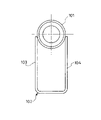
- the bracket 102 has a C-shape when viewed from the axial direction of the outer shell, and a pair of plates 103 and 104 whose tips are abutted against the side surface of the outer shell 101 in parallel with each other. May be prepared.
- the bracket 102 having such a structure is joined by welding the tips of the plates 103 and 104 to the side portions of the outer shell 101, but there is a possibility of causing welding defects.
- an object of the present invention is to provide a shock absorber capable of preventing welding defects between the outer shell and the bracket and firmly joining the two.
- the shock absorber of the present invention is attached to a shock absorber body having a cylindrical outer shell and a rod movably inserted into the outer shell, and to the outer shell by welding. It is equipped with a bracket that connects the outer shell to the components of the vehicle, and each bracket has a pair of holding pieces that extend toward the outer shell side and sandwich the outer shell in the radial direction, and the tip of each holding piece is the outer shell. When viewed from the axial direction, it protrudes beyond half of the outer shell toward the anti-component side to form a gap with the outer shell, and is attached to the outer periphery of the outer shell by welding.
- shock absorber configured in this way, a pocket with a large volume that can store the filler metal during gap welding between the tip of the holding piece of the bracket and the outer circumference of the outer shell can be formed, so that the tip of the holding piece and the outer shell can be formed. It is possible to prevent the filler metal from dripping from between.
- FIG. 1 is a side view of the shock absorber in one embodiment.
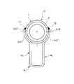
- FIG. 2 is a bottom view of the shock absorber according to the embodiment.
- FIG. 3 is an enlarged view of a tip portion of a holding piece of a bracket that holds the outer shell in one embodiment.
- FIG. 4 is a bottom view of the shock absorber in one modification of the embodiment.
- FIG. 5 is a bottom view of a conventional shock absorber.
- the shock absorber D is welded to a shock absorber body 1 having a cylindrical outer shell 2 and a rod 3 movably inserted into the outer shell 2 and an outer shell 2. It is provided with a bracket 4 which is attached by and connects the outer shell 2 to the stabilizer S as a component of the vehicle. Further, the shock absorber main body 1 is connected to a suspension arm that supports the wheels of a vehicle (not shown), and is interposed between the vehicle body and the wheels.
- the stabilizer S is provided with an unexpected torsion bar that is twisted when the left and right wheels of the vehicle are displaced in the opposite phase in the vertical direction, and suppresses the displacement of the left and right wheels in the opposite phase.
- the shock absorber main body 1 has a tubular outer shell 2 and a rod 3 that is movably inserted into the outer shell 2, and the rod 3 is expanded and contracted so as to move relative to the outer shell 2 in the axial direction. Occasionally, a damping force that hinders the relative movement of the rod 3 with respect to the outer shell 2 is generated to damp the vibration of the vehicle body and wheels.
- the shock absorber main body 1 includes, for example, a cylindrical outer shell 2 whose lower end is closed, a cylinder (not shown) housed in the outer shell 2, a rod 3 movably inserted into the cylinder, and a rod 3.
- a piston that is connected and inserted into the cylinder to divide the inside of the cylinder into an extension side chamber and a compression side chamber, a reservoir formed between the cylinder and the outer shell, and a compression side chamber and a reservoir provided at the lower end of the cylinder. It is equipped with a valve case that separates and.
- the extension side chamber and the compression side chamber are filled with a liquid such as hydraulic oil, and the reservoir is filled with the liquid and the gas.
- the liquid used for the shock absorber D may be, for example, a liquid such as water or an aqueous solution, in addition to the hydraulic oil.
- a passage connecting the extension side chamber and the compression side chamber and a passage communicating the compression side chamber and the reservoir are provided, and each of the passages is provided with a damping valve.
- the shock absorber body 1 configured in this way, the extension side chamber and the compression side chamber are expanded and contracted by the piston during expansion and contraction operation, and the liquid moves through the passage, and the flow of the liquid is attenuated by giving resistance to the flow of the liquid by the damping valve. Generates force.
- Bracket 4 is configured by bending and molding a single metal base material. As shown in FIGS. 1 and 2, the bracket 4 is formed in a C shape that sandwiches the outer peripheral side portion of the outer shell 2, and faces the rectangular facing piece 4a facing the side portion of the outer shell 2. It has a pair of holding pieces 4b, 4c that extend toward the outer shell 2 side from both ends in the direction perpendicular to the axis of the outer shell 2 in the piece 4a and sandwich the outer shell 2 in the radial direction.
- the facing piece 4a has a hole (not shown), and the stabilizer S as a component of the vehicle can be connected by a bolt. Further, the sandwiching pieces 4b and 4c extend parallelly and linearly toward the outer shell 2 side from the ends of the facing pieces 4a while maintaining a constant width with each other, and the outer shells are in the middle when viewed from the axial direction of the outer shell 2. While sandwiching the side portion of 2 in the radial direction, the tip is projected beyond half of the outer shell 2 toward the anti-component side opposite to the stabilizer S side.
- the holding pieces 4b and 4c are in contact with each other 180 degrees on the opposite side of the outer shell 2 at the circumference, and the tip thereof extends beyond half of the outer shell 2 and protrudes to the opposite side when viewed from the facing piece 4a.
- a gap G is formed. More specifically, since the outer shell 2 is cylindrical and the surface of the outer shell 2 opposite to the facing piece 4a side is curved in a direction away from the tip of the holding piece 4b (4c), the holding piece 4b, A gap G having a larger volume than that of a shock absorber provided with a conventional bracket is formed between the tip side and the outer shell 2 from the contact point of 4c with the outer shell 2.
- the bracket 4 configured in this way is joined to the outer shell 2 by arc welding the tips of the holding pieces 4b and 4c and the outer periphery of the outer shell 2 along the axial direction of the outer shell 2. More specifically, in the bracket 4, the shock absorber main body 1 is laid sideways in a state where the outer periphery of the outer shell 2 is sandwiched between the holding pieces 4b and 4c, and the tips of the holding pieces 4b and 4c face upward and the facing pieces 4a face downward. It is welded in such a posture and joined to the outer shell 2.
- the gap G shown in FIG. 3 is formed between the tips of the holding pieces 4b and 4c of the bracket 4 and the outer periphery of the outer shell 2. Further, since the sandwiching pieces 4b and 4c are in contact with the outer periphery of the outer shell 2 in the middle to sandwich the outer shell 2, they are formed between the tips of the sandwiching pieces 4b and 4c and the outer shell 2. The gap G does not lead to the facing piece 4a side of the outer shell 2. That is, a pocket is formed between the holding pieces 4b and 4c and the outer shell 2.
- bracket 4 and the outer shell 2 are arc-welded, even if the molten filler material enters the gap G described above, it does not pass through the gap G and fall downward, and the filler metal is held by the holding piece 4b. , 4c stays in place without dripping from between the tip of 4c and the outer circumference of the outer shell 2, and welded portions 11 and 12 can be formed between the two with a good bead in which the material to be welded and the filler metal are melted. .. It should be noted that the holding pieces 4b and 4c do not come into contact with each other, and even if there are some gaps between them, the filler metal must flow downward from the gap G through the gaps during welding. It's fine.
- the holding pieces 4b and 4c and the outer shell 2 do not have to be in contact with each other as long as the filler metal does not flow downward.
- the chamfered portion M may be provided at the opposite portions of the tips of the holding pieces 4b and 4c facing each other to adjust the volume of the gap G.
- the shape of the chamfered portion M can be arbitrarily changed, and may be, for example, a tapered surface or a curved surface.
- the shock absorber D of the present embodiment has a shock absorber main body 1 having a cylindrical outer shell 2 and a rod 3 movably inserted into the outer shell 2, and an outer shell.
- a pair of brackets 4 attached to the shell 2 by welding and connecting the outer shell 2 to the stabilizer (component) S of the vehicle, each extending toward the outer shell 2 side and sandwiching the outer shell 2 in the radial direction.
- the holding pieces 4b and 4c are provided, and the tips of the holding pieces 4b and 4c exceed half of the outer shell 2 when viewed from the axial direction of the outer shell 2 and are directed toward the anti-component side which is the anti-stabilizer side. It protrudes and is attached to the outer periphery of the outer shell 2 by welding.
- a pocket having a large volume capable of storing filler metal during welding can be formed in the gap G between the tips of the holding pieces 4b and 4c of the bracket 4 and the outer periphery of the outer shell 2. Therefore, it is possible to prevent the filler metal from dripping from between the tips of the holding pieces 4b and 4c and the outer shell 2. Therefore, according to the shock absorber D of the present embodiment, good welded portions 11 and 12 without welding defects can be formed between the tips of the holding pieces 4b and 4c of the bracket 4 and the outer periphery of the outer shell 2, and the bracket. 4 can be firmly joined to the outer shell 2. Further, the chamfered portion M may be provided at the opposite portions of the tips of the holding pieces 4b and 4c facing each other to adjust the volume of the pocket to optimize the joining strength.
- the length of the portion of each of the holding pieces 4b and 4c that protrudes beyond half of the outer shell 2 is too short, the volume of the pocket formed by the gap G becomes small and the filler metal overflows from the gap G. If the length of the portion that hangs down and protrudes beyond half of the outer shell 2 of each holding piece 4b, 4c is too long, the distance between the tip of each holding piece 4b, 4c and the outer circumference of the outer shell 2 May be too wide to form a good bead. Therefore, it is preferable to set the length t of the portion of each of the holding pieces 4b, 4c that protrudes beyond half of the outer shell 2 to a length of 1/15 or more and 1 / 7.5 or less of the diameter of the outer shell 2.
- the length t may be set so as to satisfy d / 15 ⁇ t ⁇ d / 7.5.
- the length t of the portion of each holding piece 4b, 4c that protrudes beyond half of the outer shell 2 is a length that deviates from the range of a length of 1/15 or more and 1 / 7.5 or less of the diameter of the outer shell 2.
- the length t is set within the above range, good welded portions 11 and 12 can be surely obtained.
- the bracket 4 has the facing piece 4a facing the side portion of the outer shell 2 and the outer shell side from both ends of the facing piece 4a in the direction perpendicular to the axis of the outer shell 2. It is provided with a pair of holding pieces 4b and 4c extending to. According to the shock absorber D configured in this way, the bracket 4 can be manufactured by bending one plate material into a C shape, the material yield of the bracket 4 is improved, and the bracket 4 can be manufactured by simple processing, so that the manufacturing cost is reduced. can.
- the holding pieces 4b and 4c in the bracket 4 have a shape extending linearly from the facing pieces 4a in parallel with each other when viewed from the axial direction of the outer shell 2. Therefore, the bracket 4 can be manufactured at low cost, and when the outer shell 2 is sandwiched between the sandwiching pieces 4b and 4c, the gap G between the sandwiching pieces 4b and 4c and the outer shell 2 does not become large or small. It is possible to prevent the situation where the bonding strength due to welding varies from product to product.
- the holding pieces 4b and 4c in the bracket 4 may include portions 4b1 and 4c1 curved along the outer periphery of the outer shell 2. Even in this way, the portions 4b2 and 4c2 on the tip side of the contact point of the holding pieces 4b and 4c with respect to the side portion are parallel to each other and have a linear shape.
- a pocket into which the filler metal can enter can be provided in the gap G of the above, and the joint strength between the bracket 4 and the outer shell 2 can be improved.
- the bracket 4 has a stabilizer S as a component of the vehicle and is suitable for connecting the shock absorber body 1 to the stabilizer S.
- the component of the vehicle other than the stabilizer S is the shock absorber body. It may be connected to 1. Therefore, for example, the component of the vehicle may be a knuckle that holds the wheels of the vehicle rotatably, or may be a component of a suspension that oscillates the wheels in the vertical direction with respect to the vehicle body.
- the shapes of the facing pieces 4a and the holding pieces 4b and 4c of the bracket 4 can be appropriately redesigned according to the components as long as the above-mentioned effects are not lost. Further, the length of the outer shell 2 at the tip of the holding pieces 4b and 4c in the axial direction can be appropriately changed in design according to the joint strength required by the specifications.
Landscapes
- Engineering & Computer Science (AREA)
- General Engineering & Computer Science (AREA)
- Mechanical Engineering (AREA)
- Vehicle Body Suspensions (AREA)
- Fluid-Damping Devices (AREA)
Priority Applications (1)
| Application Number | Priority Date | Filing Date | Title |
|---|---|---|---|
| CN202180055184.XA CN116323266A (zh) | 2020-11-25 | 2021-10-05 | 缓冲器 |
Applications Claiming Priority (2)
| Application Number | Priority Date | Filing Date | Title |
|---|---|---|---|
| JP2020194814A JP7202345B2 (ja) | 2020-11-25 | 2020-11-25 | 緩衝器 |
| JP2020-194814 | 2020-11-25 |
Publications (1)
| Publication Number | Publication Date |
|---|---|
| WO2022113526A1 true WO2022113526A1 (ja) | 2022-06-02 |
Family
ID=81755722
Family Applications (1)
| Application Number | Title | Priority Date | Filing Date |
|---|---|---|---|
| PCT/JP2021/036725 Ceased WO2022113526A1 (ja) | 2020-11-25 | 2021-10-05 | 緩衝器 |
Country Status (3)
| Country | Link |
|---|---|
| JP (1) | JP7202345B2 (https=) |
| CN (1) | CN116323266A (https=) |
| WO (1) | WO2022113526A1 (https=) |
Families Citing this family (2)
| Publication number | Priority date | Publication date | Assignee | Title |
|---|---|---|---|---|
| JP7340000B2 (ja) * | 2021-12-20 | 2023-09-06 | Kyb株式会社 | 緩衝器 |
| JP2024134625A (ja) * | 2023-03-22 | 2024-10-04 | カヤバ株式会社 | 溶接方法及び溶接構造 |
Citations (3)
| Publication number | Priority date | Publication date | Assignee | Title |
|---|---|---|---|---|
| JPH0616625U (ja) * | 1992-08-05 | 1994-03-04 | 立山アルミニウム工業株式会社 | 組立車庫 |
| JP2001182772A (ja) * | 1999-10-15 | 2001-07-06 | Showa Corp | 倒立型油圧緩衝器 |
| JP2002130360A (ja) * | 2000-10-23 | 2002-05-09 | Showa Corp | 油圧緩衝器のナックルブラケット構造 |
Family Cites Families (4)
| Publication number | Priority date | Publication date | Assignee | Title |
|---|---|---|---|---|
| JP2000154842A (ja) * | 1998-11-18 | 2000-06-06 | Kayaba Ind Co Ltd | ナックルブラケット |
| JP4180725B2 (ja) * | 1999-03-26 | 2008-11-12 | 株式会社ショーワ | ブラケット取付構造 |
| JP6116454B2 (ja) * | 2013-09-18 | 2017-04-19 | プレス工業株式会社 | トルクロッドブラケット |
| JP6420601B2 (ja) * | 2014-09-16 | 2018-11-07 | Kyb株式会社 | 緩衝器 |
-
2020
- 2020-11-25 JP JP2020194814A patent/JP7202345B2/ja active Active
-
2021
- 2021-10-05 WO PCT/JP2021/036725 patent/WO2022113526A1/ja not_active Ceased
- 2021-10-05 CN CN202180055184.XA patent/CN116323266A/zh active Pending
Patent Citations (3)
| Publication number | Priority date | Publication date | Assignee | Title |
|---|---|---|---|---|
| JPH0616625U (ja) * | 1992-08-05 | 1994-03-04 | 立山アルミニウム工業株式会社 | 組立車庫 |
| JP2001182772A (ja) * | 1999-10-15 | 2001-07-06 | Showa Corp | 倒立型油圧緩衝器 |
| JP2002130360A (ja) * | 2000-10-23 | 2002-05-09 | Showa Corp | 油圧緩衝器のナックルブラケット構造 |
Also Published As
| Publication number | Publication date |
|---|---|
| CN116323266A (zh) | 2023-06-23 |
| JP7202345B2 (ja) | 2023-01-11 |
| JP2022083481A (ja) | 2022-06-06 |
Similar Documents
| Publication | Publication Date | Title |
|---|---|---|
| WO2022113526A1 (ja) | 緩衝器 | |
| US11506251B2 (en) | Base member for a damper | |
| JP2005532228A5 (https=) | ||
| JP7177970B2 (ja) | 緩衝器 | |
| KR20130103857A (ko) | 트레일링 아암과 마찰용접되는 링부재를 갖는 토션빔 액슬 | |
| CN101239569B (zh) | 车辆用缓冲器 | |
| JP7502976B2 (ja) | 緩衝器 | |
| JP2000161414A (ja) | サスペンションストラット | |
| JP2022083481A5 (https=) | ||
| JP7340000B2 (ja) | 緩衝器 | |
| JP7777441B2 (ja) | 緩衝器 | |
| JP7481889B2 (ja) | 緩衝器 | |
| CN115038598B (zh) | 多点式导臂 | |
| JP7385537B2 (ja) | サスペンション装置 | |
| JP7063423B1 (ja) | サブフレーム | |
| JP2024134625A (ja) | 溶接方法及び溶接構造 | |
| JP4740463B2 (ja) | アウターシェルユニットおよびその溶接方法 | |
| JP6374784B2 (ja) | ナックルブラケット及び緩衝器 | |
| JP6827666B2 (ja) | トーションビーム式サスペンション | |
| JP2007147038A (ja) | シリンダ装置 | |
| JP2021167626A (ja) | 緩衝器 | |
| JP6789874B2 (ja) | 車両用ショックアブゾーバ | |
| JP4695458B2 (ja) | ストラット型ショックアブソーバ | |
| WO2016113996A1 (ja) | ショックアブソーバ | |
| JP4697867B2 (ja) | ストラット型ショックアブソーバ |
Legal Events
| Date | Code | Title | Description |
|---|---|---|---|
| 121 | Ep: the epo has been informed by wipo that ep was designated in this application |
Ref document number: 21897504 Country of ref document: EP Kind code of ref document: A1 |
|
| DPE1 | Request for preliminary examination filed after expiration of 19th month from priority date (pct application filed from 20040101) | ||
| NENP | Non-entry into the national phase |
Ref country code: DE |
|
| 122 | Ep: pct application non-entry in european phase |
Ref document number: 21897504 Country of ref document: EP Kind code of ref document: A1 |