WO2022113526A1 - Damper - Google Patents
Damper Download PDFInfo
- Publication number
- WO2022113526A1 WO2022113526A1 PCT/JP2021/036725 JP2021036725W WO2022113526A1 WO 2022113526 A1 WO2022113526 A1 WO 2022113526A1 JP 2021036725 W JP2021036725 W JP 2021036725W WO 2022113526 A1 WO2022113526 A1 WO 2022113526A1
- Authority
- WO
- WIPO (PCT)
- Prior art keywords
- outer shell
- shock absorber
- bracket
- holding
- pieces
- Prior art date
Links
- 238000003466 welding Methods 0.000 claims abstract description 21
- 239000006096 absorbing agent Substances 0.000 claims description 43
- 230000035939 shock Effects 0.000 claims description 43
- 239000003381 stabilizer Substances 0.000 claims description 12
- 238000006073 displacement reaction Methods 0.000 claims description 3
- 239000000470 constituent Substances 0.000 abstract 1
- 239000000945 filler Substances 0.000 description 17
- 239000002184 metal Substances 0.000 description 16
- 239000000463 material Substances 0.000 description 9
- 239000007788 liquid Substances 0.000 description 7
- 230000006835 compression Effects 0.000 description 6
- 238000007906 compression Methods 0.000 description 6
- 239000000725 suspension Substances 0.000 description 5
- 238000013016 damping Methods 0.000 description 4
- 239000011324 bead Substances 0.000 description 3
- 230000007547 defect Effects 0.000 description 3
- 238000005452 bending Methods 0.000 description 2
- 230000008602 contraction Effects 0.000 description 2
- 239000010720 hydraulic oil Substances 0.000 description 2
- 239000007864 aqueous solution Substances 0.000 description 1
- 230000002238 attenuated effect Effects 0.000 description 1
- 230000000694 effects Effects 0.000 description 1
- 238000004519 manufacturing process Methods 0.000 description 1
- 238000012986 modification Methods 0.000 description 1
- 230000004048 modification Effects 0.000 description 1
- 238000000465 moulding Methods 0.000 description 1
- 230000002093 peripheral effect Effects 0.000 description 1
- XLYOFNOQVPJJNP-UHFFFAOYSA-N water Substances O XLYOFNOQVPJJNP-UHFFFAOYSA-N 0.000 description 1
Images


Classifications
-
- B—PERFORMING OPERATIONS; TRANSPORTING
- B60—VEHICLES IN GENERAL
- B60G—VEHICLE SUSPENSION ARRANGEMENTS
- B60G13/00—Resilient suspensions characterised by arrangement, location or type of vibration dampers
- B60G13/02—Resilient suspensions characterised by arrangement, location or type of vibration dampers having dampers dissipating energy, e.g. frictionally
- B60G13/06—Resilient suspensions characterised by arrangement, location or type of vibration dampers having dampers dissipating energy, e.g. frictionally of fluid type
- B60G13/08—Resilient suspensions characterised by arrangement, location or type of vibration dampers having dampers dissipating energy, e.g. frictionally of fluid type hydraulic
-
- F—MECHANICAL ENGINEERING; LIGHTING; HEATING; WEAPONS; BLASTING
- F16—ENGINEERING ELEMENTS AND UNITS; GENERAL MEASURES FOR PRODUCING AND MAINTAINING EFFECTIVE FUNCTIONING OF MACHINES OR INSTALLATIONS; THERMAL INSULATION IN GENERAL
- F16F—SPRINGS; SHOCK-ABSORBERS; MEANS FOR DAMPING VIBRATION
- F16F9/00—Springs, vibration-dampers, shock-absorbers, or similarly-constructed movement-dampers using a fluid or the equivalent as damping medium
- F16F9/32—Details
- F16F9/54—Arrangements for attachment
Definitions
- the present invention relates to a shock absorber.
- the shock absorber comprises an outer shell and a rod that is movably inserted into the outer shell and is used, for example, by being incorporated into a suspension in a vehicle during expansion and contraction when the piston rod moves axially with respect to the outer shell. It exerts damping force and suppresses vibration of the car body and wheels.
- the shock absorber incorporated in the suspension in this way is attached to the lower end of the outer shell by welding and connected to the stabilizer so that it can be connected to a stabilizer that suppresses the vertical displacement of the left and right wheels of the vehicle, for example. Brackets may be provided.
- a bracket called a knuckle bracket for attaching a knuckle that holds the wheels of the vehicle may be attached to the lower end of the outer shell by welding.
- such a bracket has a C-shaped cross section for holding the outer periphery of the outer shell, and has a cylindrical holding portion and diameters from both ends in the circumferential direction of the holding portion. Some are provided with a pair of attachments that extend parallel to each other and can be connected to a knuckle outward in the direction.
- a shock absorber provided with such a bracket, the upper end surface of the holding portion and the outer periphery of the outer shell are welded to attach the bracket to the outer shell. Therefore, the filler metal melted at the time of welding the outer shell and the bracket accumulates at the upper end of the holding portion, and both can be firmly joined.
- the bracket 102 has a C-shape when viewed from the axial direction of the outer shell, and a pair of plates 103 and 104 whose tips are abutted against the side surface of the outer shell 101 in parallel with each other. May be prepared.
- the bracket 102 having such a structure is joined by welding the tips of the plates 103 and 104 to the side portions of the outer shell 101, but there is a possibility of causing welding defects.
- an object of the present invention is to provide a shock absorber capable of preventing welding defects between the outer shell and the bracket and firmly joining the two.
- the shock absorber of the present invention is attached to a shock absorber body having a cylindrical outer shell and a rod movably inserted into the outer shell, and to the outer shell by welding. It is equipped with a bracket that connects the outer shell to the components of the vehicle, and each bracket has a pair of holding pieces that extend toward the outer shell side and sandwich the outer shell in the radial direction, and the tip of each holding piece is the outer shell. When viewed from the axial direction, it protrudes beyond half of the outer shell toward the anti-component side to form a gap with the outer shell, and is attached to the outer periphery of the outer shell by welding.
- shock absorber configured in this way, a pocket with a large volume that can store the filler metal during gap welding between the tip of the holding piece of the bracket and the outer circumference of the outer shell can be formed, so that the tip of the holding piece and the outer shell can be formed. It is possible to prevent the filler metal from dripping from between.
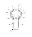
- FIG. 1 is a side view of the shock absorber in one embodiment.
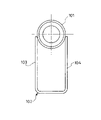
- FIG. 2 is a bottom view of the shock absorber according to the embodiment.
- FIG. 3 is an enlarged view of a tip portion of a holding piece of a bracket that holds the outer shell in one embodiment.
- FIG. 4 is a bottom view of the shock absorber in one modification of the embodiment.
- FIG. 5 is a bottom view of a conventional shock absorber.
- the shock absorber D is welded to a shock absorber body 1 having a cylindrical outer shell 2 and a rod 3 movably inserted into the outer shell 2 and an outer shell 2. It is provided with a bracket 4 which is attached by and connects the outer shell 2 to the stabilizer S as a component of the vehicle. Further, the shock absorber main body 1 is connected to a suspension arm that supports the wheels of a vehicle (not shown), and is interposed between the vehicle body and the wheels.
- the stabilizer S is provided with an unexpected torsion bar that is twisted when the left and right wheels of the vehicle are displaced in the opposite phase in the vertical direction, and suppresses the displacement of the left and right wheels in the opposite phase.
- the shock absorber main body 1 has a tubular outer shell 2 and a rod 3 that is movably inserted into the outer shell 2, and the rod 3 is expanded and contracted so as to move relative to the outer shell 2 in the axial direction. Occasionally, a damping force that hinders the relative movement of the rod 3 with respect to the outer shell 2 is generated to damp the vibration of the vehicle body and wheels.
- the shock absorber main body 1 includes, for example, a cylindrical outer shell 2 whose lower end is closed, a cylinder (not shown) housed in the outer shell 2, a rod 3 movably inserted into the cylinder, and a rod 3.
- a piston that is connected and inserted into the cylinder to divide the inside of the cylinder into an extension side chamber and a compression side chamber, a reservoir formed between the cylinder and the outer shell, and a compression side chamber and a reservoir provided at the lower end of the cylinder. It is equipped with a valve case that separates and.
- the extension side chamber and the compression side chamber are filled with a liquid such as hydraulic oil, and the reservoir is filled with the liquid and the gas.
- the liquid used for the shock absorber D may be, for example, a liquid such as water or an aqueous solution, in addition to the hydraulic oil.
- a passage connecting the extension side chamber and the compression side chamber and a passage communicating the compression side chamber and the reservoir are provided, and each of the passages is provided with a damping valve.
- the shock absorber body 1 configured in this way, the extension side chamber and the compression side chamber are expanded and contracted by the piston during expansion and contraction operation, and the liquid moves through the passage, and the flow of the liquid is attenuated by giving resistance to the flow of the liquid by the damping valve. Generates force.
- Bracket 4 is configured by bending and molding a single metal base material. As shown in FIGS. 1 and 2, the bracket 4 is formed in a C shape that sandwiches the outer peripheral side portion of the outer shell 2, and faces the rectangular facing piece 4a facing the side portion of the outer shell 2. It has a pair of holding pieces 4b, 4c that extend toward the outer shell 2 side from both ends in the direction perpendicular to the axis of the outer shell 2 in the piece 4a and sandwich the outer shell 2 in the radial direction.
- the facing piece 4a has a hole (not shown), and the stabilizer S as a component of the vehicle can be connected by a bolt. Further, the sandwiching pieces 4b and 4c extend parallelly and linearly toward the outer shell 2 side from the ends of the facing pieces 4a while maintaining a constant width with each other, and the outer shells are in the middle when viewed from the axial direction of the outer shell 2. While sandwiching the side portion of 2 in the radial direction, the tip is projected beyond half of the outer shell 2 toward the anti-component side opposite to the stabilizer S side.
- the holding pieces 4b and 4c are in contact with each other 180 degrees on the opposite side of the outer shell 2 at the circumference, and the tip thereof extends beyond half of the outer shell 2 and protrudes to the opposite side when viewed from the facing piece 4a.
- a gap G is formed. More specifically, since the outer shell 2 is cylindrical and the surface of the outer shell 2 opposite to the facing piece 4a side is curved in a direction away from the tip of the holding piece 4b (4c), the holding piece 4b, A gap G having a larger volume than that of a shock absorber provided with a conventional bracket is formed between the tip side and the outer shell 2 from the contact point of 4c with the outer shell 2.
- the bracket 4 configured in this way is joined to the outer shell 2 by arc welding the tips of the holding pieces 4b and 4c and the outer periphery of the outer shell 2 along the axial direction of the outer shell 2. More specifically, in the bracket 4, the shock absorber main body 1 is laid sideways in a state where the outer periphery of the outer shell 2 is sandwiched between the holding pieces 4b and 4c, and the tips of the holding pieces 4b and 4c face upward and the facing pieces 4a face downward. It is welded in such a posture and joined to the outer shell 2.
- the gap G shown in FIG. 3 is formed between the tips of the holding pieces 4b and 4c of the bracket 4 and the outer periphery of the outer shell 2. Further, since the sandwiching pieces 4b and 4c are in contact with the outer periphery of the outer shell 2 in the middle to sandwich the outer shell 2, they are formed between the tips of the sandwiching pieces 4b and 4c and the outer shell 2. The gap G does not lead to the facing piece 4a side of the outer shell 2. That is, a pocket is formed between the holding pieces 4b and 4c and the outer shell 2.
- bracket 4 and the outer shell 2 are arc-welded, even if the molten filler material enters the gap G described above, it does not pass through the gap G and fall downward, and the filler metal is held by the holding piece 4b. , 4c stays in place without dripping from between the tip of 4c and the outer circumference of the outer shell 2, and welded portions 11 and 12 can be formed between the two with a good bead in which the material to be welded and the filler metal are melted. .. It should be noted that the holding pieces 4b and 4c do not come into contact with each other, and even if there are some gaps between them, the filler metal must flow downward from the gap G through the gaps during welding. It's fine.
- the holding pieces 4b and 4c and the outer shell 2 do not have to be in contact with each other as long as the filler metal does not flow downward.
- the chamfered portion M may be provided at the opposite portions of the tips of the holding pieces 4b and 4c facing each other to adjust the volume of the gap G.
- the shape of the chamfered portion M can be arbitrarily changed, and may be, for example, a tapered surface or a curved surface.
- the shock absorber D of the present embodiment has a shock absorber main body 1 having a cylindrical outer shell 2 and a rod 3 movably inserted into the outer shell 2, and an outer shell.
- a pair of brackets 4 attached to the shell 2 by welding and connecting the outer shell 2 to the stabilizer (component) S of the vehicle, each extending toward the outer shell 2 side and sandwiching the outer shell 2 in the radial direction.
- the holding pieces 4b and 4c are provided, and the tips of the holding pieces 4b and 4c exceed half of the outer shell 2 when viewed from the axial direction of the outer shell 2 and are directed toward the anti-component side which is the anti-stabilizer side. It protrudes and is attached to the outer periphery of the outer shell 2 by welding.
- a pocket having a large volume capable of storing filler metal during welding can be formed in the gap G between the tips of the holding pieces 4b and 4c of the bracket 4 and the outer periphery of the outer shell 2. Therefore, it is possible to prevent the filler metal from dripping from between the tips of the holding pieces 4b and 4c and the outer shell 2. Therefore, according to the shock absorber D of the present embodiment, good welded portions 11 and 12 without welding defects can be formed between the tips of the holding pieces 4b and 4c of the bracket 4 and the outer periphery of the outer shell 2, and the bracket. 4 can be firmly joined to the outer shell 2. Further, the chamfered portion M may be provided at the opposite portions of the tips of the holding pieces 4b and 4c facing each other to adjust the volume of the pocket to optimize the joining strength.
- the length of the portion of each of the holding pieces 4b and 4c that protrudes beyond half of the outer shell 2 is too short, the volume of the pocket formed by the gap G becomes small and the filler metal overflows from the gap G. If the length of the portion that hangs down and protrudes beyond half of the outer shell 2 of each holding piece 4b, 4c is too long, the distance between the tip of each holding piece 4b, 4c and the outer circumference of the outer shell 2 May be too wide to form a good bead. Therefore, it is preferable to set the length t of the portion of each of the holding pieces 4b, 4c that protrudes beyond half of the outer shell 2 to a length of 1/15 or more and 1 / 7.5 or less of the diameter of the outer shell 2.
- the length t may be set so as to satisfy d / 15 ⁇ t ⁇ d / 7.5.
- the length t of the portion of each holding piece 4b, 4c that protrudes beyond half of the outer shell 2 is a length that deviates from the range of a length of 1/15 or more and 1 / 7.5 or less of the diameter of the outer shell 2.
- the length t is set within the above range, good welded portions 11 and 12 can be surely obtained.
- the bracket 4 has the facing piece 4a facing the side portion of the outer shell 2 and the outer shell side from both ends of the facing piece 4a in the direction perpendicular to the axis of the outer shell 2. It is provided with a pair of holding pieces 4b and 4c extending to. According to the shock absorber D configured in this way, the bracket 4 can be manufactured by bending one plate material into a C shape, the material yield of the bracket 4 is improved, and the bracket 4 can be manufactured by simple processing, so that the manufacturing cost is reduced. can.
- the holding pieces 4b and 4c in the bracket 4 have a shape extending linearly from the facing pieces 4a in parallel with each other when viewed from the axial direction of the outer shell 2. Therefore, the bracket 4 can be manufactured at low cost, and when the outer shell 2 is sandwiched between the sandwiching pieces 4b and 4c, the gap G between the sandwiching pieces 4b and 4c and the outer shell 2 does not become large or small. It is possible to prevent the situation where the bonding strength due to welding varies from product to product.
- the holding pieces 4b and 4c in the bracket 4 may include portions 4b1 and 4c1 curved along the outer periphery of the outer shell 2. Even in this way, the portions 4b2 and 4c2 on the tip side of the contact point of the holding pieces 4b and 4c with respect to the side portion are parallel to each other and have a linear shape.
- a pocket into which the filler metal can enter can be provided in the gap G of the above, and the joint strength between the bracket 4 and the outer shell 2 can be improved.
- the bracket 4 has a stabilizer S as a component of the vehicle and is suitable for connecting the shock absorber body 1 to the stabilizer S.
- the component of the vehicle other than the stabilizer S is the shock absorber body. It may be connected to 1. Therefore, for example, the component of the vehicle may be a knuckle that holds the wheels of the vehicle rotatably, or may be a component of a suspension that oscillates the wheels in the vertical direction with respect to the vehicle body.
- the shapes of the facing pieces 4a and the holding pieces 4b and 4c of the bracket 4 can be appropriately redesigned according to the components as long as the above-mentioned effects are not lost. Further, the length of the outer shell 2 at the tip of the holding pieces 4b and 4c in the axial direction can be appropriately changed in design according to the joint strength required by the specifications.
Landscapes
- Engineering & Computer Science (AREA)
- General Engineering & Computer Science (AREA)
- Mechanical Engineering (AREA)
- Vehicle Body Suspensions (AREA)
- Fluid-Damping Devices (AREA)
Abstract
This damper (D) comprises: a damper body (1) having a cylindrical outer shell (2) and a rod (3) movably inserted into the outer shell (2); and a bracket (4) which is attached to the outer shell (2) by welding and connects the outer shell (2) to a constituent component (S) of a vehicle, wherein: the bracket (4) has an opposing piece (4a) opposing a lateral portion of the outer shell (2), and a pair of clamping pieces (4b, 4c) which respectively extend toward the outer shell (2) from both ends of the opposing piece (4a) in a direction perpendicular to the axial line of the outer shell (2), and which clamp the outer shell (2) in the radial direction; and a distal end of each clamping piece (4b, 4c) protrudes toward the opposite opposing piece (4a) for over half of the outer shell (2) as seen from the axial line direction of the outer shell (2), and is attached to the outer periphery of the outer shell (2) by welding.
Description
本発明は、緩衝器に関する。
The present invention relates to a shock absorber.
緩衝器は、アウターシェルと、アウターシェル内に移動自在に挿入されるロッドとを備え、たとえば、車両におけるサスペンションに組み込まれて使用され、アウターシェルに対してピストンロッドが軸方向に移動する伸縮時に減衰力を発揮して車体と車輪の振動を抑制する。
The shock absorber comprises an outer shell and a rod that is movably inserted into the outer shell and is used, for example, by being incorporated into a suspension in a vehicle during expansion and contraction when the piston rod moves axially with respect to the outer shell. It exerts damping force and suppresses vibration of the car body and wheels.
このようにサスペンションに組み込まれる緩衝器は、たとえば、車両の左右輪の上下方向の逆位相の変位を抑制するスタビライザに連結できるように、アウターシェルの下端に溶接によって取付けられて前記スタビライザに連結されるブラケットを備える場合がある。
The shock absorber incorporated in the suspension in this way is attached to the lower end of the outer shell by welding and connected to the stabilizer so that it can be connected to a stabilizer that suppresses the vertical displacement of the left and right wheels of the vehicle, for example. Brackets may be provided.
また、緩衝器がストラット式サスペンションに利用される場合、アウターシェルの下端に車両の車輪を保持するナックルを取り付けるためのナックルブラケットと称されるブラケットが溶接によって取り付けられる場合がある。
Also, when a shock absorber is used for a strut suspension, a bracket called a knuckle bracket for attaching a knuckle that holds the wheels of the vehicle may be attached to the lower end of the outer shell by welding.
このようなブラケットは、たとえば、JP2009-216129Aに開示されているように、アウターシェルの外周を抱持する断面C型であって筒状の抱持部と、抱持部の周方向両端から径方向の外側へ向けて互いに平行して延びてナックルに連結可能な一対の取付部とを備えたものがある。このようなブラケットを備えた緩衝器では、抱持部の上端面とアウターシェルの外周とが溶接されてブラケットがアウターシェルに取り付けられている。よって、アウターシェルとブラケットとの溶接時に溶融した溶加材が抱持部の上端に溜まって両者を強固に接合できる。
As disclosed in JP2009-216129A, such a bracket has a C-shaped cross section for holding the outer periphery of the outer shell, and has a cylindrical holding portion and diameters from both ends in the circumferential direction of the holding portion. Some are provided with a pair of attachments that extend parallel to each other and can be connected to a knuckle outward in the direction. In a shock absorber provided with such a bracket, the upper end surface of the holding portion and the outer periphery of the outer shell are welded to attach the bracket to the outer shell. Therefore, the filler metal melted at the time of welding the outer shell and the bracket accumulates at the upper end of the holding portion, and both can be firmly joined.
このように、ブラケットがアウターシェルを抱持する抱持部を備えている場合、抱持部の上端に溶加材を溜めることができる。これに対して、ブラケット102が図5に示すように、アウターシェルの軸方向から見てC形とされて互いに平行して先端がアウターシェル101の側面に突き当てられる一対のプレート103,104を備える場合がある。
In this way, when the bracket is provided with a holding portion for holding the outer shell, the filler material can be stored at the upper end of the holding portion. On the other hand, as shown in FIG. 5, the bracket 102 has a C-shape when viewed from the axial direction of the outer shell, and a pair of plates 103 and 104 whose tips are abutted against the side surface of the outer shell 101 in parallel with each other. May be prepared.
このような構造のブラケット102は、プレート103,104の先端をアウターシェル101の側部に溶接して接合されるが、溶接不良を生じさせる可能性がある。
The bracket 102 having such a structure is joined by welding the tips of the plates 103 and 104 to the side portions of the outer shell 101, but there is a possibility of causing welding defects.
何故なら、前記ブラケット102では、プレート103,104の先端における内側の縁をアウターシェル101の外周に突き当てているため、プレート103,104の先端とアウターシェル101の外周との間に溶融した溶加材を溜めるスペースを大きく確保できない。すると、プレート103,104をアウターシェル101の側面に溶接する際に、前記スペースに溶加材をとどめておけずに、前記スペースから溶加材が流れ落ちてしまう場合がある。このような事態が生じると、ブラケット102とアウターシェル101との接合強度が低下してしまい、溶接不良となってしまう。
This is because, in the bracket 102, the inner edge at the tips of the plates 103 and 104 is abutted against the outer periphery of the outer shell 101, so that the molten metal is melted between the tips of the plates 103 and 104 and the outer periphery of the outer shell 101. It is not possible to secure a large space for storing additional materials. Then, when the plates 103 and 104 are welded to the side surface of the outer shell 101, the filler material may flow down from the space without retaining the filler metal in the space. When such a situation occurs, the joint strength between the bracket 102 and the outer shell 101 is lowered, resulting in poor welding.
そこで、本発明は、アウターシェルとブラケットの溶接不良を防止して両者を強固に接合できる緩衝器の提供を目的としている。
Therefore, an object of the present invention is to provide a shock absorber capable of preventing welding defects between the outer shell and the bracket and firmly joining the two.
前記した課題を解決するために、本発明の緩衝器は、円筒状のアウターシェルと、アウターシェル内に移動自在に挿入されるロッドとを有する緩衝器本体と、アウターシェルに溶接によって取付けられてアウターシェルを車両の構成部品に連結するブラケットとを備え、ブラケットは、それぞれアウターシェル側へ延びてアウターシェルを径方向で挟む一対の挟持片を有し、各挟持片の先端は、アウターシェルの軸線方向から見てアウターシェルの半分を超えて反構成部品側へ向けて突出してアウターシェルとの間に隙間を形成するとともに、アウターシェルの外周に溶接によって取り付けられる。
In order to solve the above-mentioned problems, the shock absorber of the present invention is attached to a shock absorber body having a cylindrical outer shell and a rod movably inserted into the outer shell, and to the outer shell by welding. It is equipped with a bracket that connects the outer shell to the components of the vehicle, and each bracket has a pair of holding pieces that extend toward the outer shell side and sandwich the outer shell in the radial direction, and the tip of each holding piece is the outer shell. When viewed from the axial direction, it protrudes beyond half of the outer shell toward the anti-component side to form a gap with the outer shell, and is attached to the outer periphery of the outer shell by welding.
このように構成された緩衝器では、ブラケットの挟持片の先端とアウターシェルの外周との隙間溶接時に溶加材を溜め得る大きな容積を持つポケットを形成できるので、挟持片の先端とアウターシェルとの間から溶加材が垂れ落ちてしまうのを防止できる。
With the shock absorber configured in this way, a pocket with a large volume that can store the filler metal during gap welding between the tip of the holding piece of the bracket and the outer circumference of the outer shell can be formed, so that the tip of the holding piece and the outer shell can be formed. It is possible to prevent the filler metal from dripping from between.
以下、図に示した実施の形態に基づき、本発明を説明する。図1および図2に示すように、緩衝器Dは、円筒状のアウターシェル2と、アウターシェル2内に移動自在に挿入されるロッド3とを有する緩衝器本体1と、アウターシェル2に溶接によって取付けられてアウターシェル2を車両の構成部品としてのスタビライザSに連結するブラケット4とを備えている。また、緩衝器本体1は、図示しない車両の車輪を支持するサスペンションアームに連結されて、車両の車体と車輪との間に介装される。スタビライザSは、車両における左右輪同士が上下方向へ逆位相で変位した際に捩じれる図外のトーションバーを備えており、左右輪の逆位相の変位を抑制する。
Hereinafter, the present invention will be described based on the embodiments shown in the figure. As shown in FIGS. 1 and 2, the shock absorber D is welded to a shock absorber body 1 having a cylindrical outer shell 2 and a rod 3 movably inserted into the outer shell 2 and an outer shell 2. It is provided with a bracket 4 which is attached by and connects the outer shell 2 to the stabilizer S as a component of the vehicle. Further, the shock absorber main body 1 is connected to a suspension arm that supports the wheels of a vehicle (not shown), and is interposed between the vehicle body and the wheels. The stabilizer S is provided with an unexpected torsion bar that is twisted when the left and right wheels of the vehicle are displaced in the opposite phase in the vertical direction, and suppresses the displacement of the left and right wheels in the opposite phase.
以下、緩衝器Dの各部について詳細に説明する。緩衝器本体1は、筒状のアウターシェル2と、アウターシェル2内に移動自在に挿入されるロッド3とを有して、ロッド3がアウターシェル2に対して軸方向に相対移動する伸縮作動時にロッド3のアウターシェル2に対する相対移動を妨げる減衰力を発生して、車両の車体と車輪の振動を減衰させる。
Hereinafter, each part of the shock absorber D will be described in detail. The shock absorber main body 1 has a tubular outer shell 2 and a rod 3 that is movably inserted into the outer shell 2, and the rod 3 is expanded and contracted so as to move relative to the outer shell 2 in the axial direction. Occasionally, a damping force that hinders the relative movement of the rod 3 with respect to the outer shell 2 is generated to damp the vibration of the vehicle body and wheels.
緩衝器本体1は、たとえば、下端が閉塞される筒状のアウターシェル2と、アウターシェル2内に収容される図示しないシリンダと、シリンダ内に移動自在に挿入されるロッド3と、ロッド3に連結されるとともにシリンダ内に挿入されてシリンダ内を伸側室と圧側室とに区画するピストンと、シリンダとアウターシェルとの間に形成されるリザーバと、シリンダの下端に設けられて圧側室とリザーバとを仕切るバルブケースとを備えている。そして、伸側室と圧側室には、作動油等の液体が充填され、リザーバには、液体と気体とが充填されている。なお、緩衝器Dに使用される液体は、作動油以外にも、たとえば、水、水溶液といった液体でもよい。
The shock absorber main body 1 includes, for example, a cylindrical outer shell 2 whose lower end is closed, a cylinder (not shown) housed in the outer shell 2, a rod 3 movably inserted into the cylinder, and a rod 3. A piston that is connected and inserted into the cylinder to divide the inside of the cylinder into an extension side chamber and a compression side chamber, a reservoir formed between the cylinder and the outer shell, and a compression side chamber and a reservoir provided at the lower end of the cylinder. It is equipped with a valve case that separates and. The extension side chamber and the compression side chamber are filled with a liquid such as hydraulic oil, and the reservoir is filled with the liquid and the gas. The liquid used for the shock absorber D may be, for example, a liquid such as water or an aqueous solution, in addition to the hydraulic oil.
また、伸側室と圧側室とを連通する通路と、圧側室とリザーバとを連通する通路とが設けられており、前記各通路には、それぞれ減衰バルブが設けられている。このように構成された緩衝器本体1は、伸縮作動時にピストンによって伸側室と圧側室とが拡縮されて液体が通路を介して移動し、この液体の流れに前記減衰バルブで抵抗を与えて減衰力を発生する。
Further, a passage connecting the extension side chamber and the compression side chamber and a passage communicating the compression side chamber and the reservoir are provided, and each of the passages is provided with a damping valve. In the shock absorber body 1 configured in this way, the extension side chamber and the compression side chamber are expanded and contracted by the piston during expansion and contraction operation, and the liquid moves through the passage, and the flow of the liquid is attenuated by giving resistance to the flow of the liquid by the damping valve. Generates force.
ブラケット4は、一枚金属の母材を折り曲げ成型して構成されている。ブラケット4は、図1および図2に示すように、アウターシェル2の外周の側部を挟持するC形に形成されており、アウターシェル2の側部に対向する矩形の対向片4aと、対向片4aにおけるアウターシェル2の軸線に垂直な方向の両端からそれぞれアウターシェル2側へ延びてアウターシェル2を径方向で挟む一対の挟持片4b,4cとを有している。
Bracket 4 is configured by bending and molding a single metal base material. As shown in FIGS. 1 and 2, the bracket 4 is formed in a C shape that sandwiches the outer peripheral side portion of the outer shell 2, and faces the rectangular facing piece 4a facing the side portion of the outer shell 2. It has a pair of holding pieces 4b, 4c that extend toward the outer shell 2 side from both ends in the direction perpendicular to the axis of the outer shell 2 in the piece 4a and sandwich the outer shell 2 in the radial direction.
対向片4aは、図示しない孔を備えており、車両の構成部品としてのスタビライザSをボルトによって連結できる。また、挟持片4b,4cは、対向片4aの端部から互いに一定の幅を保って平行かつ直線的にアウターシェル2側へ延びており、アウターシェル2の軸線方向から見て途中でアウターシェル2の側部を直径方向で挟みつつ、先端をアウターシェル2の半分を超えてスタビライザS側とは反対側となる反構成部品側へ突出させている。つまり、挟持片4b,4cは、互いにアウターシェル2に対して周で180度反対側に当接しており、先端が対向片4aからみてアウターシェル2の半分を超えて反対側へ突出している。
The facing piece 4a has a hole (not shown), and the stabilizer S as a component of the vehicle can be connected by a bolt. Further, the sandwiching pieces 4b and 4c extend parallelly and linearly toward the outer shell 2 side from the ends of the facing pieces 4a while maintaining a constant width with each other, and the outer shells are in the middle when viewed from the axial direction of the outer shell 2. While sandwiching the side portion of 2 in the radial direction, the tip is projected beyond half of the outer shell 2 toward the anti-component side opposite to the stabilizer S side. That is, the holding pieces 4b and 4c are in contact with each other 180 degrees on the opposite side of the outer shell 2 at the circumference, and the tip thereof extends beyond half of the outer shell 2 and protrudes to the opposite side when viewed from the facing piece 4a.
ブラケット4の挟持片4b,4cの先端がアウターシェル2の半分を超えて反対側へ突出すると、図3に示すように、挟持片4b(4c)の先端とアウターシェル2の外周との間に隙間Gが形成される。より詳細には、アウターシェル2が円筒状であってアウターシェル2の対向片4a側とは反対側の面が挟持片4b(4c)の先端から離間する方向へ湾曲するため、挟持片4b,4cのアウターシェル2への接触点から先端側とアウターシェル2との間に従来のブラケットを備えた緩衝器に比べて大きな容積を持つ隙間Gが形成される。
When the tips of the holding pieces 4b and 4c of the bracket 4 project beyond half of the outer shell 2 to the opposite side, as shown in FIG. 3, between the tip of the holding pieces 4b (4c) and the outer periphery of the outer shell 2. A gap G is formed. More specifically, since the outer shell 2 is cylindrical and the surface of the outer shell 2 opposite to the facing piece 4a side is curved in a direction away from the tip of the holding piece 4b (4c), the holding piece 4b, A gap G having a larger volume than that of a shock absorber provided with a conventional bracket is formed between the tip side and the outer shell 2 from the contact point of 4c with the outer shell 2.
このように構成されたブラケット4は、挟持片4b,4cの先端とアウターシェル2の外周とをアウターシェル2の軸方向に沿ってアーク溶接することでアウターシェル2に接合される。より詳細には、ブラケット4は、アウターシェル2の外周を挟持片4b,4cで挟んだ状態で緩衝器本体1を横に寝かせて挟持片4b,4cの先端が上向きに対向片4aが下向きとなるような姿勢で溶接されてアウターシェル2に接合される。
The bracket 4 configured in this way is joined to the outer shell 2 by arc welding the tips of the holding pieces 4b and 4c and the outer periphery of the outer shell 2 along the axial direction of the outer shell 2. More specifically, in the bracket 4, the shock absorber main body 1 is laid sideways in a state where the outer periphery of the outer shell 2 is sandwiched between the holding pieces 4b and 4c, and the tips of the holding pieces 4b and 4c face upward and the facing pieces 4a face downward. It is welded in such a posture and joined to the outer shell 2.
そして、ブラケット4の挟持片4b,4cの先端とアウターシェル2の外周とがアーク溶接されると、図1および図2に示したように、挟持片4b,4cの先端とアウターシェル2の外周との間に被溶接材料であるブラケット4とアウターシェル2と溶加材とが溶融した溶接ビードでなる溶接部11,12が形成される。
Then, when the tips of the holding pieces 4b and 4c of the bracket 4 and the outer periphery of the outer shell 2 are arc-welded, as shown in FIGS. 1 and 2, the tips of the holding pieces 4b and 4c and the outer periphery of the outer shell 2 are formed. Welded portions 11 and 12 made of weld beads in which the bracket 4, the outer shell 2, and the filler metal, which are the materials to be welded, are melted are formed between the two.
前述したように、ブラケット4の挟持片4b,4cの先端とアウターシェル2の外周との間に図3に示した隙間Gが形成されている。また、挟持片4b,4cが途中をアウターシェル2の外周に当接させていてアウターシェル2を挟持しているために、挟持片4b,4cの先端とアウターシェル2との間に形成される隙間Gがアウターシェル2の対向片4a側へ通じていない。つまり、挟持片4b,4cとアウターシェル2とで両者の間にポケットを形成している。
As described above, the gap G shown in FIG. 3 is formed between the tips of the holding pieces 4b and 4c of the bracket 4 and the outer periphery of the outer shell 2. Further, since the sandwiching pieces 4b and 4c are in contact with the outer periphery of the outer shell 2 in the middle to sandwich the outer shell 2, they are formed between the tips of the sandwiching pieces 4b and 4c and the outer shell 2. The gap G does not lead to the facing piece 4a side of the outer shell 2. That is, a pocket is formed between the holding pieces 4b and 4c and the outer shell 2.
よって、ブラケット4とアウターシェル2とをアーク溶接する際に、前述の隙間Gに溶融した溶加材が入り込んでも隙間Gを通過して下方へ落下することはなく、溶加材が挟持片4b,4cの先端とアウターシェル2の外周との間から垂れ落ちずにその場に留まり、両者の間に被溶接材料と溶加材とが溶融した良好なビードで溶接部11,12を形成できる。なお、挟持片4b,4cとアウターシェル2とが接触せず、両者の間に多少の空隙があっても溶接の際に隙間Gから前記空隙を介して溶加材が下方へ流れ落ちることがなければよい。このように溶加材が下方へ流れ落ちない限りにおいて、挟持片4b,4cとアウターシェル2とは、厳密には接触していなくともよい。また、図3の破線で示すように、挟持片4b,4cの先端の互い向き合う対向部位に面取り部Mを設けて隙間Gの容積を調整してもよい。なお、面取り部Mの形状は任意に変更でき、たとえば、テーパ面状や湾曲面状とされてもよい。
Therefore, when the bracket 4 and the outer shell 2 are arc-welded, even if the molten filler material enters the gap G described above, it does not pass through the gap G and fall downward, and the filler metal is held by the holding piece 4b. , 4c stays in place without dripping from between the tip of 4c and the outer circumference of the outer shell 2, and welded portions 11 and 12 can be formed between the two with a good bead in which the material to be welded and the filler metal are melted. .. It should be noted that the holding pieces 4b and 4c do not come into contact with each other, and even if there are some gaps between them, the filler metal must flow downward from the gap G through the gaps during welding. It's fine. Strictly speaking, the holding pieces 4b and 4c and the outer shell 2 do not have to be in contact with each other as long as the filler metal does not flow downward. Further, as shown by the broken line in FIG. 3, the chamfered portion M may be provided at the opposite portions of the tips of the holding pieces 4b and 4c facing each other to adjust the volume of the gap G. The shape of the chamfered portion M can be arbitrarily changed, and may be, for example, a tapered surface or a curved surface.
前述したところから理解できるように、本実施の形態の緩衝器Dは、円筒状のアウターシェル2と、アウターシェル2内に移動自在に挿入されるロッド3とを有する緩衝器本体1と、アウターシェル2に溶接によって取付けられてアウターシェル2を車両のスタビライザ(構成部品)Sに連結するブラケット4とを備え、ブラケット4は、それぞれアウターシェル2側へ延びてアウターシェル2を径方向で挟む一対の挟持片4b,4cとを有し、各挟持片4b,4cの先端は、アウターシェル2の軸線方向から見てアウターシェル2の半分を超えて反スタビライザ側となる反構成部品側へ向けて突出するとともに、アウターシェル2の外周に溶接によって取り付けられる。
As can be understood from the above, the shock absorber D of the present embodiment has a shock absorber main body 1 having a cylindrical outer shell 2 and a rod 3 movably inserted into the outer shell 2, and an outer shell. A pair of brackets 4 attached to the shell 2 by welding and connecting the outer shell 2 to the stabilizer (component) S of the vehicle, each extending toward the outer shell 2 side and sandwiching the outer shell 2 in the radial direction. The holding pieces 4b and 4c are provided, and the tips of the holding pieces 4b and 4c exceed half of the outer shell 2 when viewed from the axial direction of the outer shell 2 and are directed toward the anti-component side which is the anti-stabilizer side. It protrudes and is attached to the outer periphery of the outer shell 2 by welding.
このように構成された緩衝器Dでは、ブラケット4の挟持片4b,4cの先端とアウターシェル2の外周との間の隙間Gで溶接時に溶加材を溜め得る大きな容積を持つポケットを形成できるので、挟持片4b,4cの先端とアウターシェル2との間から溶加材が垂れ落ちてしまうのを防止できる。よって、本実施の形態の緩衝器Dによれば、ブラケット4の挟持片4b,4cの先端とアウターシェル2の外周との間に溶接不良の無い良好な溶接部11,12を形成でき、ブラケット4をアウターシェル2に強固に接合できる。また、挟持片4b,4cの先端の互い向き合う対向部位に面取り部Mを設けてポケットの容積を調整して、接合強度を最適化してもよい。
In the shock absorber D configured as described above, a pocket having a large volume capable of storing filler metal during welding can be formed in the gap G between the tips of the holding pieces 4b and 4c of the bracket 4 and the outer periphery of the outer shell 2. Therefore, it is possible to prevent the filler metal from dripping from between the tips of the holding pieces 4b and 4c and the outer shell 2. Therefore, according to the shock absorber D of the present embodiment, good welded portions 11 and 12 without welding defects can be formed between the tips of the holding pieces 4b and 4c of the bracket 4 and the outer periphery of the outer shell 2, and the bracket. 4 can be firmly joined to the outer shell 2. Further, the chamfered portion M may be provided at the opposite portions of the tips of the holding pieces 4b and 4c facing each other to adjust the volume of the pocket to optimize the joining strength.
なお、各挟持片4b,4cのアウターシェル2の半分を超えて突出する部分の長さが短すぎると、隙間Gで形成されるポケットの容積が小さくなって溶加材が隙間Gから溢れて垂れ落ちてしまい、各挟持片4b,4cのアウターシェル2の半分を超えて突出する部分の長さが長すぎると、各挟持片4b,4cの先端とアウターシェル2の外周との間の間隔が広くなりすぎて良好なビードを形成できない可能性がある。そこで、各挟持片4b,4cのアウターシェル2の半分を超えて突出する部分の長さtをアウターシェル2の直径の1/15以上1/7.5以下の長さに設定するとよい。つまり、アウターシェル2の直径dとすると、前記長さtがd/15≦t≦d/7.5を満たすように設定するとよい。このように設定すると、各挟持片4b,4cとアウターシェル2とを溶接によって接合する際に、溶加材が入り込む隙間Gの大きさが最適化されるので良好な溶接部11,12を形成して、より効果的にブラケット4をアウターシェル2に強固に接合できる。各挟持片4b,4cのアウターシェル2の半分を超えて突出する部分の長さtは、アウターシェル2の直径の1/15以上1/7.5以下の長さの範囲から逸脱した長さに設定されてもよいが、前記長さtを前記範囲内に設定すれば確実に良好な溶接部11,12が得られるのである。
If the length of the portion of each of the holding pieces 4b and 4c that protrudes beyond half of the outer shell 2 is too short, the volume of the pocket formed by the gap G becomes small and the filler metal overflows from the gap G. If the length of the portion that hangs down and protrudes beyond half of the outer shell 2 of each holding piece 4b, 4c is too long, the distance between the tip of each holding piece 4b, 4c and the outer circumference of the outer shell 2 May be too wide to form a good bead. Therefore, it is preferable to set the length t of the portion of each of the holding pieces 4b, 4c that protrudes beyond half of the outer shell 2 to a length of 1/15 or more and 1 / 7.5 or less of the diameter of the outer shell 2. That is, assuming that the diameter d of the outer shell 2 is set, the length t may be set so as to satisfy d / 15 ≦ t ≦ d / 7.5. With this setting, when the holding pieces 4b and 4c and the outer shell 2 are joined by welding, the size of the gap G into which the filler metal enters is optimized, so that good welded portions 11 and 12 are formed. Then, the bracket 4 can be firmly joined to the outer shell 2 more effectively. The length t of the portion of each holding piece 4b, 4c that protrudes beyond half of the outer shell 2 is a length that deviates from the range of a length of 1/15 or more and 1 / 7.5 or less of the diameter of the outer shell 2. However, if the length t is set within the above range, good welded portions 11 and 12 can be surely obtained.
また、本実施の形態の緩衝器Dでは、ブラケット4は、アウターシェル2の側部に対向する対向片4aと、対向片4aのアウターシェル2の軸線に垂直な方向の両端からそれぞれアウターシェル側へ延びる一対の挟持片4b,4cとを備えている。このよう構成された緩衝器Dによれば、ブラケット4を一枚の板材をC形に折り曲げ加工して製造でき、ブラケット4の材料歩留まりが良くなり簡単な加工で製造できるので、製造コストを低減できる。
Further, in the shock absorber D of the present embodiment, the bracket 4 has the facing piece 4a facing the side portion of the outer shell 2 and the outer shell side from both ends of the facing piece 4a in the direction perpendicular to the axis of the outer shell 2. It is provided with a pair of holding pieces 4b and 4c extending to. According to the shock absorber D configured in this way, the bracket 4 can be manufactured by bending one plate material into a C shape, the material yield of the bracket 4 is improved, and the bracket 4 can be manufactured by simple processing, so that the manufacturing cost is reduced. can.
また、本実施の形態の緩衝器Dでは、ブラケット4における各挟持片4b,4cは、アウターシェル2の軸線方向から見て互いに平行して対向片4aから直線状に延びている形状となっているのでブラケット4を安価に製造できるとともに、アウターシェル2を挟持片4b,4cで挟持させた際に挟持片4b,4cとアウターシェル2との間の隙間Gの間隔が大小することがないので製品毎に溶接による接合強度がばらついてしまう事態を防止できる。
Further, in the shock absorber D of the present embodiment, the holding pieces 4b and 4c in the bracket 4 have a shape extending linearly from the facing pieces 4a in parallel with each other when viewed from the axial direction of the outer shell 2. Therefore, the bracket 4 can be manufactured at low cost, and when the outer shell 2 is sandwiched between the sandwiching pieces 4b and 4c, the gap G between the sandwiching pieces 4b and 4c and the outer shell 2 does not become large or small. It is possible to prevent the situation where the bonding strength due to welding varies from product to product.
ただし、挟持片4b,4cは、アウターシェル2の側部を挟持でき、アウターシェル2の側部に接触する接触点より先端側が互いに平行して対向するとともに直線状に延びる形状となっていれば、途中の形状が互いに平行する直線的な形状となっていなくともよい。よって、ブラケット4における挟持片4b,4cは、図4に示すように、アウターシェル2の外周に沿うように湾曲した部分4b1,4c1を備えていてもよい。このようにしても、挟持片4b,4cのアウターシェル2の側部への接触点より先端側の部分4b2,4c2は互いに平行し直線的な形状となっているので、アウターシェル2との間の隙間Gで溶加材が入り込むポケットを設けることができ、ブラケット4とアウターシェル2との接合強度を向上できる。
However, if the sandwiching pieces 4b and 4c can sandwich the side portion of the outer shell 2 and have a shape in which the tip end side faces each other in parallel with each other and extends linearly from the contact point in contact with the side portion of the outer shell 2. , The shape in the middle does not have to be a linear shape parallel to each other. Therefore, as shown in FIG. 4, the holding pieces 4b and 4c in the bracket 4 may include portions 4b1 and 4c1 curved along the outer periphery of the outer shell 2. Even in this way, the portions 4b2 and 4c2 on the tip side of the contact point of the holding pieces 4b and 4c with respect to the side portion are parallel to each other and have a linear shape. A pocket into which the filler metal can enter can be provided in the gap G of the above, and the joint strength between the bracket 4 and the outer shell 2 can be improved.
なお、前述したところでは、ブラケット4は、車両の構成部品をスタビライザSとしており、緩衝器本体1をスタビライザSへ連結するのに適しているが、スタビライザS以外の車両の構成部品を緩衝器本体1に連結するものであってもよい。よって、たとえば、車両の構成部品は、車両の車輪を回転可能に保持するナックルであってもよいし、車体に対して車輪を上下方向に揺動可能に取り付けるサスペンションの一部品であってもよく、ブラケット4の対向片4aおよび挟持片4b,4cの形状を前述した効果を失わない限りにおいて構成部品に応じて適宜設計変更できる。また、挟持片4b,4cの先端のアウターシェル2の軸方向における長さについては、仕様上要求される接合強度に応じて適宜設計変更できる。
As described above, the bracket 4 has a stabilizer S as a component of the vehicle and is suitable for connecting the shock absorber body 1 to the stabilizer S. However, the component of the vehicle other than the stabilizer S is the shock absorber body. It may be connected to 1. Therefore, for example, the component of the vehicle may be a knuckle that holds the wheels of the vehicle rotatably, or may be a component of a suspension that oscillates the wheels in the vertical direction with respect to the vehicle body. The shapes of the facing pieces 4a and the holding pieces 4b and 4c of the bracket 4 can be appropriately redesigned according to the components as long as the above-mentioned effects are not lost. Further, the length of the outer shell 2 at the tip of the holding pieces 4b and 4c in the axial direction can be appropriately changed in design according to the joint strength required by the specifications.
以上、本発明の好ましい実施の形態を詳細に説明したが、特許請求の範囲から逸脱しない限り、改造、変形、および変更が可能である。
Although the preferred embodiments of the present invention have been described in detail above, they can be modified, modified, and modified as long as they do not deviate from the claims.
本願は、2020年11月25日に日本国特許庁に出願された特願2020-194814に基づく優先権を主張し、この出願の全ての内容は参照により本明細書に組み込まれる。
This application claims priority based on Japanese Patent Application No. 2020-194814 filed with the Japan Patent Office on November 25, 2020, and the entire contents of this application are incorporated herein by reference.
Claims (5)
- 緩衝器であって、
円筒状のアウターシェルと、前記アウターシェル内に移動自在に挿入されるロッドとを有する緩衝器本体と、
前記アウターシェルに溶接によって取付けられて前記アウターシェルを車両の構成部品に連結するブラケットとを備え、
前記ブラケットは、それぞれ前記アウターシェル側へ延びて前記アウターシェルを径方向で挟む一対の挟持片を有し、
各挟持片の先端は、前記アウターシェルの軸線方向から見て前記アウターシェルの半分を超えて反構成部品側へ向けて突出して前記アウターシェルとの間に隙間を形成するとともに、前記アウターシェルの外周に溶接によって取り付けられている
緩衝器。 It ’s a shock absorber,
A shock absorber body having a cylindrical outer shell and a rod movably inserted into the outer shell,
It is provided with a bracket that is welded to the outer shell and connects the outer shell to vehicle components.
Each of the brackets has a pair of holding pieces extending toward the outer shell side and sandwiching the outer shell in the radial direction.
The tip of each holding piece protrudes toward the anti-component side beyond half of the outer shell when viewed from the axial direction of the outer shell, forms a gap with the outer shell, and forms a gap between the outer shell and the outer shell. A shock absorber attached to the outer circumference by welding. - 請求項1に記載の緩衝器であって、
前記各挟持片の前記アウターシェルの半分を超えて突出する部分の長さは、前記アウターシェルの直径の1/15以上1/7.5以下の長さに設定されている
緩衝器。 The shock absorber according to claim 1.
A shock absorber whose length of a portion of each holding piece protruding beyond half of the outer shell is set to a length of 1/15 or more and 1 / 7.5 or less of the diameter of the outer shell. - 請求項1に記載の緩衝器であって、
前記ブラケットは、前記アウターシェルの側部に対向する対向片を有し、
前記挟持片は、それぞれ、前記対向片の前記アウターシェルの軸線に垂直な方向の両端から前記アウターシェル側へ延びている
緩衝器。 The shock absorber according to claim 1.
The bracket has facing pieces facing the sides of the outer shell.
Each of the holding pieces is a shock absorber extending from both ends of the facing piece in a direction perpendicular to the axis of the outer shell toward the outer shell side. - 請求項3に記載の緩衝器であって、
前記各挟持片は、前記アウターシェルの軸線方向から見て互いに平行して前記対向片から直線状に延びている
緩衝器。 The shock absorber according to claim 3.
Each of the holding pieces is a shock absorber extending linearly from the facing pieces in parallel with each other when viewed from the axial direction of the outer shell. - 請求項1から4のいずれか一項に記載の緩衝器であって、
前記構成部品は、車両における左右輪同士の上下方向の逆位相の変位を抑制するスタビライザである
緩衝器。 The shock absorber according to any one of claims 1 to 4.
The component is a shock absorber that is a stabilizer that suppresses the displacement of the left and right wheels in the vertical direction in the vehicle.
Priority Applications (1)
| Application Number | Priority Date | Filing Date | Title |
|---|---|---|---|
| CN202180055184.XA CN116323266A (en) | 2020-11-25 | 2021-10-05 | Buffer device |
Applications Claiming Priority (2)
| Application Number | Priority Date | Filing Date | Title |
|---|---|---|---|
| JP2020-194814 | 2020-11-25 | ||
| JP2020194814A JP7202345B2 (en) | 2020-11-25 | 2020-11-25 | buffer |
Publications (1)
| Publication Number | Publication Date |
|---|---|
| WO2022113526A1 true WO2022113526A1 (en) | 2022-06-02 |
Family
ID=81755722
Family Applications (1)
| Application Number | Title | Priority Date | Filing Date |
|---|---|---|---|
| PCT/JP2021/036725 WO2022113526A1 (en) | 2020-11-25 | 2021-10-05 | Damper |
Country Status (3)
| Country | Link |
|---|---|
| JP (1) | JP7202345B2 (en) |
| CN (1) | CN116323266A (en) |
| WO (1) | WO2022113526A1 (en) |
Families Citing this family (1)
| Publication number | Priority date | Publication date | Assignee | Title |
|---|---|---|---|---|
| JP7340000B2 (en) | 2021-12-20 | 2023-09-06 | Kyb株式会社 | buffer |
Citations (3)
| Publication number | Priority date | Publication date | Assignee | Title |
|---|---|---|---|---|
| JPH0616625U (en) * | 1992-08-05 | 1994-03-04 | 立山アルミニウム工業株式会社 | Assembly garage |
| JP2001182772A (en) * | 1999-10-15 | 2001-07-06 | Showa Corp | Inverted-type hydraulic shock absorber |
| JP2002130360A (en) * | 2000-10-23 | 2002-05-09 | Showa Corp | Knuckle bracket structure for hydraulic shock absorber |
-
2020
- 2020-11-25 JP JP2020194814A patent/JP7202345B2/en active Active
-
2021
- 2021-10-05 CN CN202180055184.XA patent/CN116323266A/en active Pending
- 2021-10-05 WO PCT/JP2021/036725 patent/WO2022113526A1/en active Application Filing
Patent Citations (3)
| Publication number | Priority date | Publication date | Assignee | Title |
|---|---|---|---|---|
| JPH0616625U (en) * | 1992-08-05 | 1994-03-04 | 立山アルミニウム工業株式会社 | Assembly garage |
| JP2001182772A (en) * | 1999-10-15 | 2001-07-06 | Showa Corp | Inverted-type hydraulic shock absorber |
| JP2002130360A (en) * | 2000-10-23 | 2002-05-09 | Showa Corp | Knuckle bracket structure for hydraulic shock absorber |
Also Published As
| Publication number | Publication date |
|---|---|
| CN116323266A (en) | 2023-06-23 |
| JP7202345B2 (en) | 2023-01-11 |
| JP2022083481A (en) | 2022-06-06 |
Similar Documents
| Publication | Publication Date | Title |
|---|---|---|
| TWI466797B (en) | Bicycle frame | |
| US20050156462A1 (en) | Rigid vehicle axle with integral trailing arms | |
| WO2022113526A1 (en) | Damper | |
| JP2005532228A5 (en) | ||
| JP6121888B2 (en) | Suspension device and suspension system | |
| US5622242A (en) | Shock absorber, and shock absorber, such as a MacPherson strut, with decompression stop limit bracket | |
| US7497450B2 (en) | Shrink fit suspension arrangement | |
| JP4996935B2 (en) | Stopper | |
| JP7177970B2 (en) | buffer | |
| JP7481889B2 (en) | Shock absorber | |
| JP7385537B2 (en) | suspension equipment | |
| US11506251B2 (en) | Base member for a damper | |
| JP2022083481A5 (en) | ||
| JP7340000B2 (en) | buffer | |
| JP4740463B2 (en) | Outer shell unit and welding method thereof | |
| JP6374784B2 (en) | Knuckle bracket and shock absorber | |
| WO2016113996A1 (en) | Shock absorber | |
| JP2007147038A (en) | Cylinder device | |
| JP6827666B2 (en) | Torsion beam suspension | |
| JP7083325B2 (en) | Intermediate beam suspension | |
| JP6131787B2 (en) | Vehicle suspension arm | |
| WO2022050244A1 (en) | Subframe | |
| JP6789874B2 (en) | Vehicle shock absorber | |
| JP4695458B2 (en) | Strut type shock absorber | |
| JP2021167626A (en) | Buffer |
Legal Events
| Date | Code | Title | Description |
|---|---|---|---|
| 121 | Ep: the epo has been informed by wipo that ep was designated in this application |
Ref document number: 21897504 Country of ref document: EP Kind code of ref document: A1 |
|
| DPE1 | Request for preliminary examination filed after expiration of 19th month from priority date (pct application filed from 20040101) | ||
| NENP | Non-entry into the national phase |
Ref country code: DE |
|
| 122 | Ep: pct application non-entry in european phase |
Ref document number: 21897504 Country of ref document: EP Kind code of ref document: A1 |