WO2022113396A1 - デバイスの無線受電用の筐体と、該筐体を有するデバイス - Google Patents
デバイスの無線受電用の筐体と、該筐体を有するデバイス Download PDFInfo
- Publication number
- WO2022113396A1 WO2022113396A1 PCT/JP2021/014102 JP2021014102W WO2022113396A1 WO 2022113396 A1 WO2022113396 A1 WO 2022113396A1 JP 2021014102 W JP2021014102 W JP 2021014102W WO 2022113396 A1 WO2022113396 A1 WO 2022113396A1
- Authority
- WO
- WIPO (PCT)
- Prior art keywords
- antenna
- housing
- power receiving
- receiving device
- slot
- Prior art date
- Legal status (The legal status is an assumption and is not a legal conclusion. Google has not performed a legal analysis and makes no representation as to the accuracy of the status listed.)
- Ceased
Links
Images










Classifications
-
- H—ELECTRICITY
- H02—GENERATION; CONVERSION OR DISTRIBUTION OF ELECTRIC POWER
- H02J—ELECTRIC POWER NETWORKS; CIRCUIT ARRANGEMENTS OR SYSTEMS FOR SUPPLYING OR DISTRIBUTING ELECTRIC POWER; SYSTEMS FOR STORING ELECTRIC ENERGY
- H02J50/00—Circuit arrangements or systems for wireless supply or distribution of electric power
- H02J50/005—Mechanical details of housing or structure aiming to accommodate the power transfer means, e.g. mechanical integration of coils, antennas or transducers into emitting or receiving devices
-
- H—ELECTRICITY
- H01—ELECTRIC ELEMENTS
- H01Q—ANTENNAS, i.e. RADIO AERIALS
- H01Q13/00—Waveguide horns or mouths; Slot antennas; Leaky-waveguide antennas; Equivalent structures causing radiation along the transmission path of a guided wave
- H01Q13/10—Resonant slot antennas
-
- H—ELECTRICITY
- H01—ELECTRIC ELEMENTS
- H01Q—ANTENNAS, i.e. RADIO AERIALS
- H01Q21/00—Antenna arrays or systems
- H01Q21/28—Combinations of substantially independent non-interacting antenna units or systems
-
- H—ELECTRICITY
- H01—ELECTRIC ELEMENTS
- H01Q—ANTENNAS, i.e. RADIO AERIALS
- H01Q9/00—Electrically-short antennas having dimensions not more than twice the operating wavelength and consisting of conductive active radiating elements
- H01Q9/04—Resonant antennas
- H01Q9/16—Resonant antennas with feed intermediate between the extremities of the antenna, e.g. centre-fed dipole
-
- H—ELECTRICITY
- H02—GENERATION; CONVERSION OR DISTRIBUTION OF ELECTRIC POWER
- H02J—ELECTRIC POWER NETWORKS; CIRCUIT ARRANGEMENTS OR SYSTEMS FOR SUPPLYING OR DISTRIBUTING ELECTRIC POWER; SYSTEMS FOR STORING ELECTRIC ENERGY
- H02J50/00—Circuit arrangements or systems for wireless supply or distribution of electric power
- H02J50/20—Circuit arrangements or systems for wireless supply or distribution of electric power using microwaves or radio frequency waves
-
- H—ELECTRICITY
- H02—GENERATION; CONVERSION OR DISTRIBUTION OF ELECTRIC POWER
- H02J—ELECTRIC POWER NETWORKS; CIRCUIT ARRANGEMENTS OR SYSTEMS FOR SUPPLYING OR DISTRIBUTING ELECTRIC POWER; SYSTEMS FOR STORING ELECTRIC ENERGY
- H02J50/00—Circuit arrangements or systems for wireless supply or distribution of electric power
- H02J50/80—Circuit arrangements or systems for wireless supply or distribution of electric power involving the exchange of data, concerning supply or distribution of electric power, between transmitting devices and receiving devices
-
- H—ELECTRICITY
- H01—ELECTRIC ELEMENTS
- H01Q—ANTENNAS, i.e. RADIO AERIALS
- H01Q1/00—Details of, or arrangements associated with, antennas
- H01Q1/12—Supports; Mounting means
- H01Q1/22—Supports; Mounting means by structural association with other equipment or articles
- H01Q1/24—Supports; Mounting means by structural association with other equipment or articles with receiving set
- H01Q1/241—Supports; Mounting means by structural association with other equipment or articles with receiving set used in mobile communications, e.g. GSM
- H01Q1/242—Supports; Mounting means by structural association with other equipment or articles with receiving set used in mobile communications, e.g. GSM specially adapted for hand-held use
- H01Q1/243—Supports; Mounting means by structural association with other equipment or articles with receiving set used in mobile communications, e.g. GSM specially adapted for hand-held use with built-in antennas
Definitions
- the present invention relates to a housing for wireless power reception of a device and a device having the housing.
- sensors and actuators are used in the fields of factories (FA: Factory Automation), Internet of Things (IoT: Internet of Things), home appliances, and the like. In general, there are many cases where sensors and actuators are not made wireless for power supply wiring.
- a proximity sensor when feeding a proximity sensor wirelessly, it is conceivable to provide a power receiving device such as an antenna in combination with the proximity sensor.
- a power receiving device such as an antenna
- the power receiving efficiency is lowered as compared with the case of cable wiring.
- an antenna or the like is added to the proximity sensor, there is a problem that the size of the proximity sensor is enlarged as a whole.
- the proximity sensor 10 includes a first antenna 1, a second antenna 2, and a standing wave ratio detection unit 3. And, in the second antenna 2, a detection target is provided. The change direction of the resonance frequency with respect to the change of the distance is opposite to the change direction of the resonance frequency of the first antenna 1. Further, the standing wave ratio detection unit 3 is a signal connected to the first antenna 1. The first standing wave ratio S1 on the line and the second standing wave ratio S2 on the signal line connected to the second antenna 2 are detected. "(See summary).
- Patent Document 1 two different types of antennas are provided for the proximity sensor, and in particular, a loop antenna 1 and a helical antenna 2 are provided.
- the loop antenna 1 and the helical antenna 2 do not receive the energy required for the operation of the proximity sensor.
- the loop antenna 1 and the helical antenna 2 may significantly increase the size of the proximity sensor as a whole (see FIGS. 1 and 6). Therefore, there is a risk that the usability of the proximity sensor will be reduced.
- the problem to be solved is a housing that receives energy wirelessly to supply power to the device and a device having the housing so as to suppress the expansion of the size as a whole while ensuring good power receiving efficiency. Is to provide.
- a housing that constitutes the main body of a device that is a sensor or actuator.
- the housing is equipped with a power receiving device that mainly generates an electric field or a magnetic field for wireless power supply.
- the power receiving device is at least one of a dipole antenna, a slot antenna, a monopole antenna, a chip antenna, and an inverted F antenna.
- the housing has a size in a three-dimensional space, and the expansion of the size of the housing in the three-dimensional space due to the provision of the power receiving device is limited to a maximum substantially one axial direction. Housing for the device.
- a housing that wirelessly receives energy to supply power to a device and a device having the housing so as to suppress an increase in size as a whole while ensuring good power receiving efficiency. can do. Issues, configurations and effects other than those described above will be clarified by the following description of the embodiments.
- FIG. 1 is an example of a diagram showing an embodiment of a power receiving device that receives energy wirelessly with a power transmitting device in (A) and (B).
- FIG. 2 is an example of a diagram illustrating a conventional proximity sensor.
- FIG. 3 is an example of a diagram illustrating a change in output when the voltage of the proximity sensor is lowered.
- FIG. 4 is an example of a diagram illustrating a change in output when the voltage of the proximity sensor is lowered.
- FIG. 5 is an example of a diagram illustrating a power receiving device.
- FIG. 6 is an example of a diagram illustrating the radiation of two different types of antennas in three-dimensional space.
- FIG. 7 is an example of a graph showing the efficiencies of two different types of antennas.
- FIG. 1 is an example of a diagram showing an embodiment of a power receiving device that receives energy wirelessly with a power transmitting device in (A) and (B).
- FIG. 2 is an example of a diagram illustrating a conventional proximity sensor
- FIG. 8 is an example of a perspective view of a proximity sensor with two different types of antennas.
- FIG. 9 is an example of a diagram illustrating the radiation of two different types of antennas in three-dimensional space.
- FIG. 10 is an example of a graph showing the efficiencies of two different types of antennas.
- FIG. 11 is an example of a diagram illustrating a means for increasing the efficiency of a power receiving device by using a closed space.
- FIG. 12 is an example of a graph showing the efficiency of FIG. 11.
- FIG. 13 is an example of a diagram illustrating a means for increasing the efficiency of a power receiving device by using a closed space and a reflecting surface.
- FIG. 14 is an example of a diagram illustrating means for increasing the efficiency of a power receiving device using a metasurface.
- FIG. 15 is an example of a diagram showing a modified example of the power receiving system.
- FIG. 16 is an example of a diagram illustrating an example of modification of the power receiving device.
- FIG. 17 is an example of a diagram illustrating an example of modification of the power receiving device.
- FIG. 18 is an example of a diagram illustrating an example of modification of the power receiving device. It is an example of the figure which compared the conventional sensor of FIG. 2 with the modification example of FIG.
- FIG. 20 is an example of a graph showing the efficiencies of three different types of antennas.
- FIG. 21 is an example of a diagram illustrating an actuator having two different antennas.
- FIG. 22 is an example of a diagram illustrating the radiation of two different antennas in three-dimensional space.
- FIG. 23 is an example of a graph showing the efficiencies of two different antennas.
- FIG. 24 is an example of a diagram illustrating the impedance change due to the power receiving device of FIG. 20.
- FIG. 25 is an example of a perspective view of an actuator with two different antennas and bolts.
- FIG. 26 is an example of a diagram illustrating the front view and the perspective view of FIG. 25.
- FIG. 27 is an example of a diagram illustrating the radiation of two different antennas in three-dimensional space.
- FIG. 28 is an example of a graph showing the efficiencies of two different antennas.
- FIG. 29 is an example of a diagram illustrating the impedance change due to the power receiving device of FIG. 21.
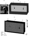
- FIG. 30 is an example of a simulation diagram of the power receiving state of the power receiving device of FIG. 25.
- FIG. 31 is an example of a diagram in which an inverted-F antenna is provided in the housing of the device.
- FIG. 32 is an example of a diagram in which an LED is provided in the housing of the actuator.
- FIG. 33 is an example of a diagram in which an inverted-F antenna is provided in the housing of the device.
- the power receiving system 1 includes at least a power receiving device 20 and a device 30.
- the power receiving device 20 receives the energy E transmitted from the power transmitting device 10 in a wireless manner to supply power to the device 30. Therefore, the power receiving device 20 completely eliminates the need to wire a physical cable for power supply to and from the power transmitting device 10. Further, the power receiving device 20 is integrally configured with the device 30 to be fed. Therefore, the power receiving device 20 completely eliminates the need to wire a physical cable for power supply to and from the device 30.
- the power receiving system 1 can include other components 30, 40.
- the power receiving device 20 is defined as a device capable of receiving power of energy E transmitted wirelessly and supplying power to the device 30.
- the power transmission device 10 that acts as a pair with the power receiving device 20 is defined as a device capable of transmitting energy E wirelessly.
- the device 30 is a device in which the energy required for operation is supplied from the power receiving device 20.
- the device 30 is a sensor or actuator.
- a sensor is defined as an electronic device that measures a physical quantity and produces the measurement result.
- An actuator is defined as an electronic device that changes a physical quantity based on an input signal.
- the sensors include proximity sensors, MR sensors, Hall elements, displacement sensors, inspection sensors, discrimination sensors, measurement sensors, length measurement sensors, vibration sensors, microphotosensors, pressure sensors, flow rate sensors, temperature / humidity sensors, etc.
- Human sensor wear sensor, acceleration sensor, strain sensor, force sensor, CMOS sensor, photoelectric sensor, laser sensor, ultrasonic sensor, touch sensor, linear cage, potentialometer, image sensor, color sensor, LiDAR sensor, TOF sensor, Seismic sensor, gyro sensor, tilt sensor, rotation sensor, angle sensor, rotation meter, load cell, false sensor, torque sensor, liquid level sensor, liquid leakage / water detection sensor, non-contact temperature sensor, current sensor, power sensor, electrostatic It may be a sensor, an isolator, or the like.
- the actuator may be an electric actuator, a hydraulic actuator, a pneumatic actuator, a chemical actuator, a magnetic fluid actuator, an electroviscous fluid actuator or the like.
- the power receiving system 1 including at least the power receiving device 20 and the device 30 can be applied to various application examples, for example, various applications such as a factory (FA: Factory Automation), the Internet of Things (IoT: Internet of Things), and home appliances. Applicable in the field.
- the power receiving system 1 is built in a machine 100 such as an industrial robot (including a machine tool) or a domestic robot (including a home appliance).
- the machine 100 can be configured to be used for various purposes such as pinching, lifting (picking), placing (placeting), assembling, painting, welding, etc. of a work or part W.
- the machine 100 is an articulated robot that performs operations with a high degree of freedom.
- the power receiving system 1 can be applied to various application examples other than the illustrated machine 100.
- the power receiving system 1 may be installed so as to supply power to a sensor that detects an object on a factory line such as a proximity sensor or a magnetic sensor in all FA devices.
- the power receiving system 1 may be installed so as to monitor the state of the office environment such as temperature / humidity and illuminance sensors in the overall building management.
- the power receiving system 1 built in the articulated robot 100 will be illustrated.
- the articulated robot 100 generally has a plurality of (at least two) axes or joints J1a, J1b, J2a, J2b, J2c in order to operate the robot arm portion 110 and / or the robot hand portion 120 with a high degree of freedom.
- the articulated robot 100 can operate with a higher degree of freedom as the number of joints J1a, J1b, J2a, J2b, and J2c increases, but more precise control is required accordingly.
- the smaller the number of joints J1a, J1b, J2a, J2b, and J2c the simpler the mechanism and the less likely the malfunction occurs.
- the wiring state of the sensor 30 of the prior art is illustrated.
- the movement of the joints J1a, J1b, J2a, J2b, and J2c of the articulated robot 100 causes problems such as a burden on the wiring of the sensor 30 (see FIG. 2), disconnection of the wiring, or maintenance of the wiring.
- various parts such as actuators are generally incorporated inside, so that the space for wiring is limited. There was a problem.
- the wiring is corroded by oil or the like, there is a risk of disconnection. In this embodiment, it is possible to avoid the above wiring problem.
- the power receiving system 1 can be applied to various machines 100 in any embodiment.
- the power receiving system 1 does not need to accommodate all the components in the fingers of the robot hand unit 120 illustrated in FIG. 1 (A).
- the relatively large and bulky parts may be configured to have flexibility and may be rolled up and stored in the finger space.
- some parts may be arranged at a place away from the finger (for example, the base of the finger of the robot hand unit 120 or a wide place in the vicinity).
- some parts can project to the outside of the machine 100 as needed.
- the power transmission device 10 is arranged at an appropriate place outside the articulated robot 100, and wirelessly transmits energy E to the power receiving device 20 via the power transmission antenna 12. is doing.
- wireless power transfer is preferably performed between the power transmission device 10 and the power receiving device 20 by a microwave method. In the microwave method, energy E or electric power can be transmitted relatively far away.
- a proximity sensor will be illustrated as a specific example of the device 30.
- the proximity sensor 30 is a device used for the purpose of detecting a detection target without touching the detection target.
- Various types of proximity sensors 30 are known, and for example, there is one that reacts when a metal approaches. Since the proximity sensor 30 is non-contact, there is no deterioration such as wear, and it has the advantages of being waterproof and dustproof, and not easily broken. In particular, the type that reacts with metal has the advantage of being less susceptible to dust and water droplets and having less false detection.
- detection distances of the proximity sensor 30, includes an inductive proximity sensor, a capacitive proximity sensor, a magnetic proximity sensor, and the like.
- the inductive proximity sensor mainly detects metal conductors such as iron, aluminum, brass, and copper.
- metal conductors such as iron, aluminum, brass, and copper.
- the magnetic loss due to the eddy current generated on the conductor surface due to the influence of the external magnetic field is detected.
- an AC magnetic field is generated in the detection coil to detect a change in impedance due to an eddy current generated in a metal body as a detection body.
- Capacitive proximity sensors mainly detect metals, resins, liquids, powders, etc. (depending on the permittivity).
- the principle is to detect changes in capacitance that occur between the detector and the sensor. For example, when a metal or a dielectric approaches, the electrostatic capacitance between the electrode inside the sensor and the ground potential increases due to the electrostatic induction effect. The oscillation amplitude increases according to the change in the capacitance of this electrode, and the approach of the detected object is detected.
- the magnetic proximity sensor is mainly a magnet to be detected.
- a magnet drives the switch lead piece.
- the switch is turned on by turning on the reed switch.
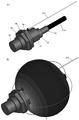
- an inductive proximity sensor 30 is exemplified, and a detection coil (not shown), an oscillation circuit, an oscillation state detection circuit, and an oscillation state detection circuit, which are not shown in the housing 31 constituting the main body, are illustrated. It houses the output circuit.
- a detection surface 32 is provided on one end side of the housing 31 so that a high frequency magnetic field emitted from the detection coil can be emitted based on an oscillation circuit.
- the proximity sensor 30 needs to be powered in order to perform the above detection operation and generate an electric signal.
- the proximity sensor 30 is provided with a connector (mounting portion) 33 for wiring on the end side of the housing 31 on the side opposite to the detection surface 32.
- the connector 33 is usually made of metal, and a power receiving cable is connected therein (see (B) in FIG. 2).
- the diameter of the detection surface 32 is about 18 mm
- the length of the housing 31 in the longitudinal direction is about 35 mm.
- the shape and size of the housing 31 and the detection surface 32 and the like are not limited to this aspect.
- the housing 31 can be configured in various ways.
- the housing 31 has a diameter-expanded portion that is partially expanded in diameter so that it can be tightened and fixed (reference numerals 34 and 35). , 36).
- the nuts 34 and 35 and the washer 36 may be provided as the diameter-expanded portion so that the housing 31 can be tightened and fixed. Therefore, the housing 31 can be separated into two with the enlarged diameter portion as a boundary.
- the proximity sensor 30 needs to be provided in close proximity to the object for the purpose of detecting the object.
- a situation may occur in which the proximity sensor 30 collides with the work W. In such a case, the proximity sensor 30 may be damaged. Therefore, it is said that the frequency of replacement of the proximity sensor 30 is relatively high. For example, the proximity sensor 30 may be replaced about once every three months.
- Replacing the wiring of the proximity sensor 30 requires two steps, cable installation and cable routing (see (C) in FIG. 2).
- various lineups of cable lengths of the proximity sensor 30 such as 2 m, 5 m, and 10 m are prepared, and it is necessary to attach each cable to a controller or the like according to the equipment.
- the above-mentioned trouble means that the labor cost of the factory worker is incurred.
- the above-mentioned problem is dealt with by receiving the energy E sent from the power transmission device 10 by the power receiving device 20 and supplying power to the proximity sensor 30 by the microwave method.
- the microwave method there is an upper limit to the capacity of the energy E that can be transmitted.
- the energy receiving efficiency is lowered as compared with the case of wired.
- the amount of power that can be supplied from the power transmitting device 10 to the power receiving device 20 is attenuated in inverse proportion to the square of the distance according to the Fleece law.
- the proximity sensor 30 operates at about 12 to 24 V and 3 to 1000 mA. That is, when converted into electric power, it is necessary to consume at least 36 mW of electric power. However, in microwave power transfer, only about 1 to 10 mW of electric power may be supplied to a power supply target 1 m ahead. That is, in order to wirelessly supply power to the proximity sensor 30, reducing the power consumption of the proximity sensor 30 is one of the issues.
- the above-mentioned "reduction of power consumption of proximity sensor” may be solved by newly developing a proximity sensor 30 for a specific application for low power consumption.
- the existing proximity sensor 30 compatible with 12 to 24 V is used as it is, thereby eliminating the need for new development of a low power consumption type proximity sensor. Therefore, the applicant conducted the following tests.
- proximity to a change in power supply voltage when a voltage lower than the recommended value is supplied to two different types of commercially available proximity sensors (a and b) compatible with 12 to 24 V. It shows the transition of the power of the sensor.
- the horizontal axis of the graph shows the supply voltage (V)
- the vertical axis shows the electric power (mW).
- the transition of the electric power of the proximity sensor when the power supply voltage is further lowered is shown.
- the power consumption is about 6mW. That is, it was confirmed that the proximity sensor 30 can be operated if the supply amount is about 10 mW.
- the power requirement can be satisfied even when the supply voltage is considerably lowered from the recommended value for the existing proximity sensor corresponding to 12 to 24V. In this case, it is possible to avoid the need to research and develop a new proximity sensor compatible with 5 to 6 V.
- the proximity sensor behaves differently from the normal time (when operating at the recommended value of 12 to 24 V).
- the output waveform shown by the proximity sensor 30 when the power supply voltage is considerably lowered (to 6 V or less) from the recommended value is shown.
- the output voltage appears as a plus when the object is not nearby (see V0), but when the object is detected, the output voltage appears as a large minus (see V1).
- object detection Low output
- the proximity sensor periodically outputs the output voltage as positive (see V0) and negative (see V1) even though the object detection time continues.
- T period the period of this intermittent operation
- the state in which the proximity sensor indicates intermittent operation is set to the low power mode (about one-fifth of the operating cost compared to the existing operation method).
- a mode that enables operation with electric power a state in which the power supply voltage of the proximity sensor satisfies the recommended value and the proximity sensor does not show intermittent operation.
- the low power mode may include a mode that enables operation with operating power of less than one-third to about one-fifth as compared with the existing operation method.
- the proximity sensor 30 exhibits an intermittent operation (see (A) in FIG. 4), there is a problem in using the output as it is.
- this embodiment in such a case, there is no need to detect the object (there is no object), or the object is detected after a long time interval (the object is exchanged), and the state where the object is present. It is possible to separate the above by devising a circuit. That is, the period T period of the intermittent operation appears at a relatively short time interval as illustrated in (A) of FIG. Since the magnitude of this time interval is substantially proportional to the power supply voltage as illustrated in FIG. 4B, it can be estimated based on the power supply voltage. Therefore, it is possible to determine whether or not the proximity sensor is detecting an object by utilizing the fact that the intermittent operation of the proximity sensor can be predicted based on the power supply voltage.
- the power receiving system 1 includes a power receiving device 20, a proximity sensor 30, a periodic filter 40, and a controller 50.
- the output of the proximity sensor 30 is passed through the periodic filter 40 and then transmitted to the controller 50.
- the periodic filter 40 is an element capable of separating a relatively fast High / Low change (low power mode, at the time of object detection) and no change (state without an object). For example, it is assumed that a voltage of 5.5 V is supplied to the proximity sensor (a) with reference to FIG. 4 (B). At this time, it can be inferred that the proximity sensor (a) operates intermittently with a period T period of 20.4 msec.
- the output of the proximity sensor 30 is passed through the periodic filter 40 corresponding to the magnitude of this cycle.
- the power receiving system 1 even when the conventional proximity sensor 30 of about 12 to 24 V is operated in the low power mode (about 5 to 6 V), it is necessary to avoid erroneous recognition of the sensor output. Can be done.
- the power receiving system 1 is not limited to the configuration shown in FIG. 1 (B).
- the power receiving system 1 can be applied to various types of devices (sensors or actuators) 30, and depending on the type of device 30, the device 30 may be operated in a normal power mode as well as a low power mode. Therefore, the power receiving system 1 does not necessarily have to include the periodic filter 40.
- the power receiving device 20 used in the power receiving system 1 exemplified in FIGS. 1 to 4 will be described.
- the power receiving device 20 is configured as a power receiving antenna.
- the power receiving antenna is configured by using the housing 31 (see (A) in FIG. 2) that constitutes the main body of the device 30 to be fed, the power receiving device 20 is provided integrally with the device 30. ..
- FIG. 5A illustrates a case where a dipole antenna 21 is used as the power receiving device 20.
- a dipole antenna 21 is attached to the housing 31 of the proximity sensor 30 to function as an antenna that generates field emission.
- the proximity sensor 30 has a main body or a housing 31 made of metal, but the periphery of the dipole antenna 21 must not be made of metal, and must be made of resin or the like (not metal).
- FIG. 5B illustrates a case where a slot antenna 22 is used as the power receiving device 20.
- a slot antenna 22 is used as the power receiving device 20.
- an appropriate cavity is provided inside the metal housing 31 of the proximity sensor 30, and a slot is formed so as to penetrate the wall thereof to function as an antenna that generates magnetic field radiation.
- the one shown in (C) of FIG. 5 illustrates a case where the dipole antenna 21 and the slot antenna 22 are used in combination as the power receiving device 20.
- the dipole antenna 21 and the slot antenna 22 are continuously and linearly arranged in the longitudinal direction.
- These two antennas 21 and 22 have a length of about 300 mm as a whole.
- the dipole antenna 21 and the slot antenna 22 shown in FIG. 5 (C) are provided so as to be aligned in the same direction with each other. However, the directions of action of both antennas appear to be orthogonal to each other. This is because the dipole antenna 21 acts mainly based on the electric field, but the slot antenna 22 acts mainly based on the magnetic field, so that the directions of action intersect.
- FIG. 6A schematically shows the directivity of the dipole antenna 21.
- FIG. 6B schematically shows the directivity of the slot antenna 22.
- the darker the hue the stronger the directivity of each antenna.
- the dipole antenna 21 has a region where the directivity of the antenna is weakened as shown by reference numeral 21A.
- the slot antenna 22 has a region where the directivity of the antenna is strengthened, as shown by reference numeral 21B. Since these regions 21A and 21B overlap each other, the deterioration of the function of the dipole antenna 21 can be compensated for by the function of the slot antenna 22 in the X-axis direction.
- the dipole antenna 21 has a region where the directivity of the antenna is strengthened, as shown by reference numeral 22A.
- the slot antenna 22 has a region where the directivity of the antenna is weakened, as shown by reference numeral 22B. Since these regions 22A and 22B overlap each other, the deterioration of the function of the slot antenna 22 can be compensated for by the function of the dipole antenna 21 in the Y-axis direction.
- the dipole antenna 21 has a region where the directivity of the antenna is strengthened, as shown by reference numeral 23A.
- the slot antenna 22 has a region where the directivity of the antenna is weakened, as shown by reference numeral 23B. Since these regions 23A and 23B overlap each other, the deterioration of the function of the slot antenna 22 can be compensated for by the function of the dipole antenna 21 in the Z-axis direction.
- the directivity of the dipole antenna 21 and the slot antenna 22 does not appear uniformly in the three-dimensional space, but appears with different strengths, but the distribution is different between the two.
- the region where the directivity of the dipole antenna 21 is weakened can be supplemented by the slot antenna 22, and vice versa. Therefore, the two antennas 21 and 22 are configured to complement each other in the directivity of the antennas. Therefore, as a whole, the combination of the antennas 21 and 22 is configured to be able to receive power in almost all directions without showing any particular loss of directivity.
- this configuration can be achieved only by arranging the two antennas 21 and 22 in a straight line with each other, and it is not necessary to adjust the orientations of both antennas in a complicated manner.
- each antenna can exhibit a high efficiency of more than about 99% when the frequency is changed from 0.8 to 1.0 GHz. Therefore, it was confirmed that the power receiving device 20 shown in FIGS. 5A to 5C can suitably receive electric power.
- FIGS. 8 to 10 a specific mounting example of the power receiving device 20 schematically illustrated in FIGS. 5 to 7 will be described with reference to FIGS. 8 to 10.
- FIG. 8 a perspective view of the proximity sensor 30 integrally provided with the power receiving device 20 according to the present embodiment is shown. The figure corresponds to an implementation example in which the dipole antenna 21 and the slot antenna 22 illustrated in FIG. 5C are combined.
- a dipole antenna 21 is provided at the end of the metal housing 31 of the proximity sensor 30 as the power receiving device 20.
- the proximity sensor 30 has a metal connector 33 for feeding by wire (see FIG. 2), but a dipole antenna 21 may be attached by using this portion.
- the dipole antenna 21 has a rod-shaped main body and extends linearly along the longitudinal direction of the housing 31.
- the cable for wiring is extended from the end opposite to the detection surface 32 of the housing 31 (see (C) in FIG. 2), but in the present embodiment, such a cable is used.
- a dipole antenna 21 is attached to the end of the housing 31 by eliminating the need for an unnecessary cable and utilizing the vacant space.
- the metal of the conventional connector 33 of the proximity sensor is used as the GND of the antenna. Therefore, the dipole antenna 21 may be provided in the housing 31 by replacing the conventional connector 33.
- a vertically long slot is formed along the longitudinal direction on the metal housing 31 of the proximity sensor 30, and a slot antenna 22 is provided. ing.
- This slot penetrates the wall of the housing 31 in the thickness direction of the housing 31.
- This slot extends linearly along the longitudinal direction of the housing 31, but is provided so as not to penetrate the end of the housing 31 (see reference numeral 37).
- the coil or circuit can be covered with metal or resin in order to protect the internal coil or circuit from the intrusion of oil.
- the housing 31 is made of non-metal, it acts as a slot antenna 22 by adhering a metal film to the slot penetrating the wall of the housing 31 or adding a metal component. It is possible to make it.
- the dipole antenna 21 and the slot antenna 22 are arranged so as to be linearly continuous with each other along the longitudinal direction of the housing 31 of the proximity sensor 30. .. In the height direction, the dipole antenna 21 and the slot antenna 22 are offset from each other (see reference numeral 38). This difference in height does not cause any particular disadvantage in the directivity of each antenna.
- the housing 31 has a size in the three-dimensional space (X-axis, Y-axis, and Z-axis directions), and the size in the three-dimensional space of the housing 31 due to the provision of the power receiving devices 21 and 22.
- the expansion of is limited to a maximum of substantially one axis direction (X-axis direction). Especially in the case of the slot antenna 22, the expansion of the size of the housing 31 can be completely eliminated.
- the power receiving device 20 is mounted on the housing 31 of the proximity sensor 30 without significantly changing the configuration of the existing proximity sensor 30.
- the power receiving device 20 preferably includes a dipole antenna 21 and a slot antenna 22, and can receive energy E from all directions.
- the antennas 21 and 22 may be functionally connected to a rectifier in the housing 31.
- the rectifier is an element having a rectifying function that causes a current to flow in only one direction, and converts RF (electromagnetic waves) received by the antennas 21 and 22 into DC (direct current voltage).
- the antennas 21 and 22 and the rectifier may be integrally configured. As described below, the rectifier may be integrated with the chip antenna. In this way, the antennas 21 and 22 may rectify and convert microwaves into direct current.
- the proximity sensor 30 When the proximity sensor 30 is used in the FA machine 100 or the like, oil resistance is required. When oil is used in the vicinity of the machine 100 or inside or outside the machine 100, the oil is applied to the housing 31 of the proximity sensor 30, and its corrosion becomes a problem. Therefore, the material of the housing 31 of the proximity sensor 30 is selected in consideration of oil resistance.
- antennas dipole antenna 21 and slot antenna 22
- antennas may be incorporated in the housing 31 of the proximity sensor 30 in consideration of the problem peculiar to FA. At this time, by arranging the antenna by utilizing the metal of the housing 31, it is possible to have an advantage peculiar to wireless power transfer by microwave in energy harvesting.
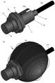
- FIG. 9 the result of simulating the power receiving situation of each of the antennas 21 and 22 in the three-dimensional space is shown based on the configuration shown in FIG.
- FIG. 9A shows the directivity of the dipole antenna 21.
- FIG. 9B shows the directivity of the slot antenna 22. In these figures, it is shown that the darker the hue, the stronger the directivity intensity of the antennas 21 and 22.
- the region where the directivity of the slot antenna 22 is weakened can be supplemented by the region where the directivity of the dipole antenna 21 is strengthened, as in the case shown in FIG. Further, in the region where the directivity of the dipole antenna 21 is weakened, it can be supplemented by the region where the directivity of the slot antenna 22 is strengthened. Therefore, the two antennas 21 and 22 of different types are configured to complement each other in the region where the directivity of both antennas is weakened. Therefore, as a whole, these antennas 21 and 22 can receive power in almost all directions without showing any particular loss of directivity.
- the omnidirectional antenna that can be used for the factory antenna that makes the best use of the radiation characteristics of the dipole antenna 21 and the slot antenna 22 has been verified by simulation. As a result, it was confirmed that the radiation patterns were formed so as to be orthogonal to each other at 90 degrees even though the antennas 21 and 22 were provided in the same direction (longitudinal direction of the proximity sensor). Therefore, this embodiment constitutes an omnidirectional omnidirectional antenna that utilizes the shape of the existing sensor 30 as it is.
- the dipole antenna 21 shows a high efficiency of about 99% and the slot antenna 22 shows a high efficiency of about 86% when the frequency is changed from 0.8 to 1.0 GHz. It was verified to get. Therefore, it was verified that the configuration using the slot antenna 21 and the dipole antenna 22 illustrated in FIG. 8 in combination is particularly suitable.
- the power receiving efficiency of the power receiving device 20 is lower than that in the case of being wired.
- the power may be received by only about 0.4% at a distance of 1 m.
- FIG. 11B an example is illustrated in which the power transmitting device 10 and the power receiving device 20 are housed in a chamber (box) 90 that internally defines a closed space (space) of a rectangular parallelepiped. ing.
- the chamber 90 improves the efficiency of transmitting energy E wirelessly between the power transmitting device 10 and the power receiving device 20 by confining the power transmitting device 10 and the power receiving device 20 in a closed space defined inside.
- the chamber 90 can accommodate all or a part of the machine 100 illustrated in FIG. 1.
- the chamber 90 has a rectangular parallelepiped shape or a polygonal shape, and this shape can be variously changed depending on the embodiment.
- the corners do not have to be formed at right angles and can be chamfered or the like. Therefore, the number of sides of the chamber 90 is not limited to six. Further, the shape of each side surface of the chamber 90 is not limited to a quadrangle.
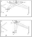
- FIG. 11 (C) the result of simulating the movement of the electromagnetic wave in the chamber 90 illustrated in FIG. 11 (B) is shown.
- the situation at that time is illustrated in (A) of the figure.
- the electromagnetic wave transmitted in the chamber 90 is reflected by each side surface that defines the boundary of the chamber 90.
- this electromagnetic wave is reflected innumerably in the enclosed space, and energy is confined in the chamber 90. Therefore, the power receiving device 20 can receive the energy transmitted from the power transmitting device 10 from various directions. Therefore, the power receiving device 20 can receive energy from multiple directions as compared with the case where energy is received from only one direction without using the chamber 90 (see reference numeral E in FIG. 1A).
- the simulation result when the frequency (GHz) is taken on the horizontal axis and the efficiency (dB) of each antenna is taken on the vertical axis is shown.
- the magnitude is shown in dB by taking five parameters (see S1,1, S3,1, S2,2, S3,2, S3,3 in FIG. 14). From this simulation result, it was confirmed that a performance improvement of at least 5 times was obtained in the chamber 90, and a performance improvement of about 6 times was generally obtained.
- a stirring fan 91 is installed as an electromagnetic wave reflecting means on the ceiling of the chamber 90.
- the stirring fan 91 is configured such that the pair of reflecting surfaces 93 and 94 rotate in a fan shape or a propeller shape with the rotation shaft 92 as the center.
- the pair of reflecting surfaces 93 and 94 extend in opposite directions in the longitudinal direction, respectively, and extend linearly as a whole.
- the number, size, shape, angle, etc. of the reflecting surfaces 93 and 94 can be variously changed according to the embodiment.
- the stirring fan 91 reflects the electromagnetic waves escaping upward from the lower part of the chamber 90 to the ceiling on the surfaces of the reflective surfaces 93 and 94, thereby re-energizing the lower part. Can be sent. Therefore, the power receiving device 20 can receive the energy reflected and transmitted from the stirring fan 91 in addition to the energy directly transmitted from the power transmitting device 10 and the energy transmitted by reflecting the wall of the chamber 90.
- the reflective surfaces 93 and 94 are configured to be movable so that they can follow changes in the position of the power receiving device 20.
- the pair of reflective surfaces 93, 94 rotate about a central rotation axis 92 so that the stirring fan 91 is relative to the chamber 90.
- the position may be changed. Therefore, as illustrated in FIG. 1A, when the power receiving device 20 changes its position relative to the power transmitting device 10, the stirring fan 91 rotates according to the change in the position, and the reflecting surface. Change the positions of 93 and 94. As a result, it is possible for the power receiving device 20 to always receive energy with high efficiency by following the change in the position of the power receiving device 20.
- the pair of reflective surfaces 93, 94 when the pair of reflective surfaces 93, 94 extend almost straight along the longitudinal direction of the chamber 90, the energy escaping upward from the power transmission device 10 is applied in the longitudinal direction. Can be reflected and sent farther (vertically). Therefore, it is suitable when straightness of energy is required at the time of power transmission.
- FIG. 13B when the pair of reflective surfaces 93 and 94 extend substantially in the intersecting direction along the longitudinal direction of the chamber 90, the energy escaping upward from the power transmission device 10 is transmitted in the longitudinal direction. It can be sent by reflecting in the direction (lateral direction) that intersects the direction. Further, the pair of reflecting surfaces 93 and 94 can be variously adjusted in the position and direction in which energy is reflected by rotating around the central rotation axis 92.
- a fixed reflecting surface 95 can be further installed on the side surface of the chamber 90.
- each side of the chamber 90 reflects electromagnetic waves.
- the reflecting surface 95 can reflect electromagnetic waves with a reflectance different from that of the side surface of the chamber 90.
- the electromagnetic waves reflected in the chamber 90 may be directed toward the power receiving device 20 more intensively.
- the reflective surface 95 may be configured as a metasurface. In this way, reflected waves can be used to maximize the received power of the receiver in medium- and long-distance wireless power transfer.
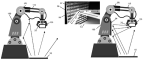
- a metasurface 96 is provided as a fixed reflecting surface on the side surface of the machine 100 is exemplified.
- the FA robot 100 since the robot arm unit 110, the robot hand unit 120, the main body of the robot 100, and the like are made of metal, a large number of reflected waves are present. Therefore, as illustrated in FIG. 14A, the reflected wave can be used to reflect the electromagnetic wave toward the power receiving device 20.
- the metasurface 96 is configured by arranging a plurality of small elements 98 on the substrate 97. The shape and arrangement of each element 98 are determined so that a suitable reflection efficiency can be obtained. Therefore, the metasurface 96 can reflect electromagnetic waves and collect them toward the power receiving device 20. As a result, the energy transmitted from the power transmission device 10 can be more efficiently transmitted to the power receiving device 20.
- the power receiving device 20 of this embodiment constitutes an omnidirectional omnidirectional antenna that utilizes the shape of the existing device (sensor or actuator) 30 as it is.
- the power receiving efficiency of the power receiving device 20 can be improved by using the chamber 90.
- a stirring fan 91 may be provided in the chamber 90.
- the power receiving efficiency of the power receiving device 20 may be further improved.
- FIG. 15 a modified example of the power receiving system 1 illustrated in FIG. 1 (B) is illustrated.
- the system 1 shown in the figure is a power receiving device 20 that wirelessly receives energy from the power transmitting device 10, a device (proximity sensor) 30 that is fed by the power receiving device 20, and a device (periodic filter) that adjusts the output of the device 30. ) 40 and the controller 50.
- the proximity sensor 30 recognizes the position of the object W by the change in the magnetic field, it generates a signal, but in the low power consumption mode, a periodic signal (H / L) is generated. By passing the signal through the periodic filter 40, a signal (L) similar to that in the normal power mode can be obtained.
- the controller 50 can utilize the output result of the proximity sensor 30 without erroneous recognition.
- the controller 50 has a microcomputer and a wireless communication function, and further transmits a signal transmitted from the proximity sensor 30 to an external controller 60 and uses it for controlling the machine tool 70.
- the machine tool 70 may be all or part of the machine 100, or may be another machine.
- making the device 30 driveable by wireless power supply means that if the data transmission can be made wireless, the device 30 can be made completely wireless.
- the proximity sensor 30 is expected to be driven at about 6 mW, and the data transmission thereof is expected to be driven at about 1 mW. Therefore, if the power receiving device 20 can supply energy of about 7 mW to the proximity sensor 30, the proximity sensor 30 can be completely wireless.
- the microwave type wireless power supply it is possible to supply power up to about 10 mW to the power supply target 1 m away, so that the proximity sensor 30 can be completely wireless. This also applies to sensors and actuators different from the proximity sensor 30.
- the power receiving device 20 may supply power only to the device 30. Further, as shown in FIG. 15, the power receiving device 20 may supply power to the periodic filter 40 and the controller 50 in addition to the device 30. Further, another power source can be added to the power receiving system 1. For example, as shown in FIG. 15, it is possible to combine the proximity sensor 30 with the vibration power generation element 80 in order to secure the minimum power supply voltage of the proximity sensor 30.
- a periodic filter 40 is included in order to achieve complete wirelessization of the proximity sensor 30 without requiring new development of the proximity sensor, but this element may be unnecessary depending on the device to be fed.
- the periodic filter 40 and the controller 50 are compared with respect to the periodic filter 40 and the controller 50.
- the power receiving system 1 illustrated in FIGS. 1B and 15 may be extended so as to feed forward the information.
- the power receiving device 20 is configured so as to utilize the radiation characteristics of the dipole antenna 21 and / or the slot antenna 22.
- the power receiving device 20 is not limited to this embodiment.
- the power receiving device 20 is at least one of a dipole antenna, a slot antenna, a monopole antenna, a chip antenna, and an inverted F antenna.
- a perspective view in which a short dipole antenna 210 is provided as a power receiving device 20 on a housing 31 of a device (proximity sensor) 30 is exemplified.
- the dipole antenna 210 is provided with a relatively short length so as to suppress the portion protruding from the housing 31.
- the dipole antenna 210 may be configured by using the connector 33 of the conventional proximity sensor 30.
- the slot antenna is not provided on the housing 31 as a difference from the embodiment illustrated in FIG. For this reason, since the housing 31 is completely sealed, when it is applied to the machine 100 by FA or the like, it completely prevents surrounding oil or the like from entering the housing 31.
- FIG. 17 a perspective view in which a slot antenna 220 is bored as a power receiving device 20 on a housing 31 of a proximity sensor 30 is exemplified.
- the part painted in black corresponds to the dipole antenna 210 of FIG. 16A, so that the positions and sizes of both antennas can be compared.
- the housing 31 of the proximity sensor 30 can be variously configured by the manufacturer.
- the slot antenna 220 may be bored by using the existing proximity sensor 30 housing 31 as it is, or a new housing 31 having a slot may be designed.
- the length of the slot that can be horizontally formed on the housing 31 may be limited. ..
- a difference from the embodiment illustrated in FIG. 8 is that a relatively large housing 31 is provided so that the housing 31 extends straight in the horizontal direction, and a step is provided. (See reference numeral 38 in FIG. 8) is eliminated, making it possible to drill a slot of sufficient length. For example, about 70%, about 80%, about 90%, or about 100% with respect to the overall length of the housing 31 in the major axis direction (from the end on the 34 side to the end on the 33 side of the main body 31). Slots of any length may be drilled.
- the coil or circuit can be covered with metal or resin in order to protect the internal coil or circuit from the intrusion of oil.
- FIG. 17 (B) the simulation result of the power receiving state of the slot antenna 220 illustrated in FIG. 17 (A) is shown.
- the directivity of the antenna similar to that in the case illustrated in FIG. 9B can be ensured.
- a perspective view in which a monopole antenna 230 is provided as a power receiving device 20 on a housing 31 of a proximity sensor 30 is exemplified.
- the part painted in black corresponds to the dipole antenna 210 of FIG. 16A, so that the positions and sizes of both antennas can be compared.
- the monopole antenna 230 also referred to as a rod antenna, has a smaller diameter and is more elongated than the dipole antenna 210.
- the nuts 34, 35 and the washer 36 for tightening and fixing the housing 31 are close to each other.
- one end of the monopole antenna 230 is mounted on the housing 31, and the other end extends straight in the opposite direction.
- FIG. 18B the simulation result of the power receiving state of the monopole antenna 230 illustrated in FIG. 18A is shown. Comparing (B) of FIG. 16 and (B) of FIG. 18, it was confirmed that the directivity of the antenna of the dipole antenna 210 and the directivity of the antenna of the monopole antenna 230 appear in the same direction. It was confirmed that good directivity was obtained even when the monopole antenna 230 was used instead of the dipole antenna 210. Further, by comparing (B) of FIG. 17 and (B) of FIG. 18, it was confirmed that the directivity of the antenna of the monopole antenna 230 and the directivity of the antenna of the slot antenna 220 intersect each other.
- the housing 31 of the conventional proximity sensor 30 extends in the longitudinal direction, but its size is L0.
- the housing 31 of the proximity sensor 30 has a diameter-expanded portion (see reference numerals 34, 35, 36) for tightening and fixing on one end side, and has a connector 33 on the other end side.
- the monopole antenna 230 is provided in close proximity to the diameter-expanded portion for tightening and fixing, and is directed toward the other end 33 along the longitudinal direction of the housing 31. Extends in the same direction (parallel to the longitudinal direction of the housing 31). As a result, the length L1 of the elongated monopole antenna 230 is the length L2 to the end 33 on the opposite side of the diameter-expanded portion for tightening and fixing the housing 31, and the length L2 in the longitudinal direction of the housing 31. You can immerse yourself in the length L0.
- the extension L3 having a size in the uniaxial direction in the three-dimensional space due to the addition of the monopole antenna 230 to the housing 31 has a length L0 in the longitudinal direction of the housing. It can be suppressed to twice or less at the maximum. Depending on the embodiment, the extension L3 having a size in the uniaxial direction in the three-dimensional space may be suppressed to 1.5 times or less at the maximum with respect to the length L0 in the longitudinal direction of the housing. Further, by making L1 bendable, the length of L3 may be suppressed to substantially zero.
- the monopole antenna 230 is completely housed within the original size of the housing 31 in the width W0 direction of the housing 31.
- the length of the housing 31 extends, but since wiring is not required (see (C) in FIG. 2), it is substantially L3. The space problem due to the length of the is suppressed.
- the housing 31 has a size in the three-dimensional space (X-axis, Y-axis, and Z-axis directions), and the size of the housing 31 in the three-dimensional space is expanded by providing the monopole antenna 230.
- the monopole antenna 230 was limited to a maximum of substantially one axis direction (X-axis direction).
- the power receiving efficiency of the antenna is shown for each of the three types of modification illustrated in FIGS. 16 to 19. As can be understood from the figure, it was found that the power receiving efficiency was the lowest when only the dipole antenna 210 having a relatively short length was used. Further, when the slot antenna 220 is provided, although it does not reach 90%, it exceeds 80%, and relatively good power receiving efficiency can be achieved. Furthermore, it was found that when the monopole antenna 230 was used, its power receiving efficiency was significantly enhanced, and it showed an ideal value close to 100%.
- the power receiving device 20 provides good power receiving efficiency in each of the six directions (front-back, left-right, up-down 6 directions) in the three-dimensional space. It is desirable to keep. It was found that when only a short dipole antenna 210 was used, good power receiving efficiency could be exhibited only at a relatively small angle with respect to a change in the rotation angle. However, as a whole, it can show relatively good stability in 6 directions.
- the monopole antenna 230 When the monopole antenna 230 is used, the best power receiving efficiency can be shown (see FIG. 20). However, since it is necessary to attach an elongated rod-shaped component to the proximity sensor 30, the structure tends to be bulky as a whole. In particular, the monopole antenna 230 has a smaller diameter and a longer overall length than the dipole antenna 210. Therefore, at the time of use, it is necessary to secure a space so that the elongated rod-shaped antenna portion does not get damaged due to contact with other parts or the like.
- the slot antenna 220 does not require additional parts to protrude from the housing 31 of the proximity sensor 30, so it has the most compact structure as a whole and is a conventional device. There is an advantage that the size of the housing 31 of 30 is not changed.
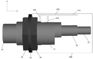
- the inverted-F antenna 400 includes an elongated main body portion 410, a short-circuit portion 420, and a feeding portion 430.
- the major axis direction (X-axis direction) of the main body 410 is aligned with the major axis direction of the housing 31, and the protrusion from the housing 31 due to the provision of the inverted F antenna 400 is suppressed.
- the main body 410 can contribute to both matching and radiation (power reception).
- the input impedance may be adjusted (for example, increased) by suppressing the current of the feeding portion 430 while passing a relatively large current through the tip of the main body portion 410 and the short-circuited portion 420.
- the inverted F antenna 400 can be attached to the device 30 without requiring a large space.
- the inverted-F antenna 400 can be configured shorter than the simple monopole antenna 230 (see FIGS. 18 and 19). Further, the inverted-F antenna 400 can facilitate the control of impedance matching. Since the inverted-F antenna 400 has many adjustment parameters due to its configuration, it can correspond to various specifications by selecting an appropriate shape.
- the separation distance between the short-circuit portion 420 and the feeding portion 430 may be adjusted. Further, the width and length of the short-circuited portion 420 and the feeding portion 430 may be adjusted. Further, the positions of the short-circuited portion 420 and the feeding portion 430 may be exchanged. That is, the short-circuit portion 430 and the feeding portion 420 may be used.
- the main body 410 may be formed in a substantially rod shape (narrow width) and its length may be adjusted. A curved portion may be introduced in the main body portion 410.
- the main body 410 may be configured in a substantially L shape. Further, the main body 410 may be formed in a substantially plate shape (wide) and its length may be adjusted.
- the power receiving device 20 can have a slot antenna (see FIG. 17) that mainly generates a magnetic field and an inverted F antenna (see FIG. 31) that mainly generates an electric field.
- the slot antenna and the inverted F antenna are aligned substantially in the same direction with each other, and the slot antenna and the inverted F antenna are omnidirectional omnidirectional antennas having radiation or power receiving patterns substantially orthogonal to each other. May be configured.
- a planar or linear chip antenna is similarly attached to the device housing 31. It is possible (not shown).
- a linear chip antenna can be thought of like a monopole antenna.
- a cover 500 (see FIG. 31) that covers the elongated antenna portion may be used in combination.
- the cover 500 can have an arbitrary size and shape so as to protect the antenna portion from contact with surrounding parts and the like.
- the cover 500 may be detachably configured with respect to the housing 31 so that it can be removed during use.
- an actuator is exemplified as the device 30 to be fed by the power receiving device 20.
- the actuator 300 is a mechanical element constituting a mechanical / electric circuit that converts an electric signal into a physical motion.
- the actuator 300 has a housing 310 that constitutes a substantially rectangular body.
- the housing 310 extends longitudinally, defining a space therein and accommodating the moving portion 350.
- the moving portion 350 performs operations such as expansion / contraction / bending / turning by a physical device such as a machine, oil / pneumatic pressure, heat, and electromagnetic waves.
- FIG. 21 (B) a cross-sectional view of the actuator 300 is schematically shown.
- the moving portion 350 housed in the housing 310 acts electromagnetically based on the input signal so that the moving portion 352 projects outward from the inside of the housing 310 with respect to the fixed portion 354. Has been done.
- the movement of the proximity component (not shown) is controlled by the protruding / immersive operation of the moving portion 352.
- the actuator 300 has a rectangular parallelepiped housing 310.
- This rectangular parallelepiped may include additional aspects for design or functional purposes.
- mounting grooves 311 to 318 extending in the longitudinal direction are bored on the four side surfaces of the housing 310. These groove portions 311 to 318 act in pairs with other convex portions (not shown) to fit the housing 310 and fix it in a predetermined position. Thereby, the operation of the moving portion 350 is prevented from being deviated.
- grooves or holes 321 to 324 can be appropriately formed on the side surface of the housing 310. Further, it is optional to process the housing 310 due to surface treatment for releasing heat inside the housing 310 to the outside, design reasons, and the like.
- a first slot (notch) 330 is inserted in at least one side surface of the four side surfaces around the housing 310 so as to extend along the longitudinal direction. ..
- a space is defined inside the housing 310 to accommodate the moving portion 350.
- the first slot 330 penetrates the wall of the housing in the thickness direction and reaches the space.
- the first slot 330 can function as the first slot antenna.
- At least one side surface of the four side surfaces around the housing 310 is provided with a second slot (cut) 340 in a direction intersecting the longitudinal direction.
- the second slot 340 penetrates the wall of the housing in the thickness direction and reaches the space.
- the second slot 340 can function as a second slot antenna.
- the second slot 340 may be provided as a perpendicular bisector with respect to the first slot 330. Therefore, the first slot 330 and the second slot 340 intersect each other in a cross shape.
- the length, position, and number of the first slot 330 and the second slot 340 are determined in consideration of the radiation pattern of electromagnetic waves.
- the first slot 330 extends only on the upper side surface.
- the first slot 330 may further extend over four sides: an upper side, a right side, a left side (not shown), and a lower side.
- the number of the first slots 330 may be plural.
- the second slot 340 extends over three sides: an upper side, a right side, and a left side (not shown).
- the second slot 340 may further extend over four sides: an upper side, a right side, a left side (not shown), and a lower side.
- the number of the second slots 340 may be plural.
- the first slot 330 and the second slot 340 extend straight in parallel with the side surface of the housing 310, respectively. This facilitates processing. However, in another embodiment, it is possible to extend the housing 310 at an angle with respect to the side surface in consideration of the function, design purpose, and the like. Further, the first slot 330 and the second slot 340 are not completely separated from each other and partially intersect with each other. However, in other embodiments, the two slots 330, 340 may be provided so as to be completely separated from each other. However, preferably, the first slot 330 and the second slot 340 are orthogonal to each other at an angle of 90 degrees.
- FIGS. 23 (A) and 23 (B) the directional electromagnetic field simulation results of the antennas in the three-dimensional space for the two different slot antennas 330 and 340 exemplified in FIG. 22 (A) are shown. Shows. This simulation assumes that power is supplied by reference numerals E1 and E2 in FIG. Each of the antennas 330 and 340 appears as omnidirectional. The directivity of each antenna 330 and 340 appears to be different in strength from each other. Therefore, by using these two antennas 330 and 340 in combination, the directivity of each can be complemented with each other.
- each antenna 330, 340 was verified to have a high efficiency of 70-80%.
- E1 achieves high efficiency of about 80%
- E2 achieves high efficiency of about 75%.
- the simulation results of impedance characteristics of the actuator 300 illustrated in FIG. 21 are shown.
- the power received by each antenna 330, 340 provides a good change in impedance characteristics.
- the impedance is suppressed to a value close to 0 ⁇ .
- the omnidirectional omnidirectional antennas 330 and 340 can be obtained only by cutting (cutting, etc.) the housing 310 of the conventional actuator 300. At this time, since other parts are not added to the housing 310 to project the housing 310, the mounting space of the conventional actuator 300 is not changed. In particular, there is no structural change on the working surface (moving portion 350) side of the actuator. Therefore, it can be used in almost the same manner as the conventional actuator 300.
- a monopole antenna, a dipole antenna, or a chip is further mounted on the housing 310 in addition to the slot antennas 330 and 340, or in place of the slot antennas 330 and 340. -It is possible to add an antenna, a reverse F antenna, etc.
- slot antennas 330 and 340 are provided by drilling slots on the housing 310.
- the actuator 300 illustrated in FIGS. 25 to 30 corresponds to a modified example of the slot antenna 330 and 340.
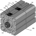
- FIG. 25 a perspective view of the actuator 300 is illustrated. Hereinafter, only the differences from the actuator 300 illustrated in FIG. 21 (A) will be described.
- a first slot antenna 330 and a second 340 are bored on the housing 310 of the actuator 300, and a power receiving IC for improving the power receiving efficiency is further formed on each slot antenna 330 and 340.
- the substrates 360 and 370 of the above are provided respectively.
- FIGS. 26A and 26B cross-sectional views of the front side and the side surface side of the actuator 300 of FIG. 25 are schematically illustrated.
- bolts 361 and 362 and a rectifier 363 are provided on the substrate 360.
- bolts 371 and 372 and a rectifier 373 are provided on the substrate 370.
- the rectifiers 363 and 373 may be configured as a chip / antenna integrated type.
- the power feeding board 360 and 370 are provided, but in reality, the slots 330 and 340 of the housing 310 are antennas.
- the slots 330 and 340 of the housing 310 are antennas.
- Two bolts 361, 362, 371, and 372 are provided on each of the boards 360 and 370, respectively. Of these, two bolts 361 and 362 are juxtaposed in the lateral direction on one of the substrates 360. Two bolts 371 and 372 are arranged side by side in the vertical direction on the other substrate 370. Therefore, each set of bolts 361, 362 and 371, 372 that carry an electric current are arranged orthogonal to each other.
- the number of bolts 361, 362, 371, and 372 on each of the substrates 360 and 370 may be two or more. These bolts do not have a surface coating, and may be added on the condition that the conductor is short-circuited and the screws do not loosen even when the robot moves violently.
- each slot antenna 330 and 340 is configured to generate radiation in the slot portion and function as an antenna.
- the bolts 361, 362, 371, and 372 on the substrate 360 and 370 function to pass an electric current.
- the rectifiers 363 and 373 are elements having a rectifying function that allow current to flow in only one direction, and convert RF (electromagnetic waves) received by each antenna 330 and 340 into DC (direct current voltage).
- a chip antenna can be further provided integrally on the substrate 360 and 370.
- Two bolts 361, 362, 371, and 372 are provided on each of the substrates 360 and 370, respectively, and the number can be changed according to the embodiment.
- Chip antennas include linear antennas such as dipole antennas and monopole antennas, and planar antennas, but in this embodiment, planar antennas are used. Since the chip antenna can be used as it is by using the metal portion of the housing 310 of the actuator 300, the area efficiency can be further improved as compared with the dipole antenna or the monopole antenna. In addition, various materials can be applied to the chip antenna, and for example, ceramics or the like may be used.
- each of the antennas 330 and 340 appears as omnidirectional.
- the directivity of each antenna 330 and 340 appears to be different in strength from each other. Therefore, by using these two antennas 330 and 340 in combination, the directivity of each can be complemented with each other.
- FIG. 28 the simulation results of the radiation efficiencies of the two different slot antennas 330 and 340 and the substrates 360 and 370 illustrated in FIG. 25 are shown. Similar to FIG. 23, in general, each antenna 330, 340 was verified to have a high efficiency of nearly 70%. Note that FIG. 23 corresponds to an ideal power supply, whereas FIG. 28 corresponds to a more realistic power supply. Therefore, in the case of FIG. 28, the efficiency is slightly lower than that of FIG. 23. There is.
- the simulation results of impedance characteristics of the actuator 300 illustrated in FIG. 25 are shown.
- the power received by each antenna 330, 340 and the substrate 360, 370 yields a good change in impedance characteristics.
- the impedance is suppressed to a value close to 0 ⁇ .
- FIG. 30 the simulation result of the surface current distribution of the actuator 300 illustrated in FIG. 25 is shown.
- current can be suitably distributed along the positions of each antenna 330, 340. Therefore, it was confirmed that each antenna 330 and 340 can work well.
- a light emitting diode (LED) 600 is mounted on the main body 310 of the actuator 300 is shown.
- the LED 600 is connected to the output of the power receiving device via a switch (not shown).
- the switch is turned on and a voltage exceeding a predetermined threshold value flows through the LED 600, the lamp of the LED 600 is configured to light up. The lighting of the LED 600 can be visually confirmed from the outside of the actuator 300.
- the user for example, an inspector
- the intensity of the light emitted by the LED 600 is approximately proportional to the amount of current flowing. It is preferable to reduce the frequency or duration of lighting of the LED 600 as much as possible in order to prevent waste of available power in wireless power transfer.
- the switch of the LED 600 may be turned on so as to minimize the influence on the power feeding operation before or after the start of use of the power receiving device.
- an acoustic device such as a buzzer on the main body 310 of the actuator 300 instead of the LED 600.
- the buzzer can be configured to emit a sound when a voltage exceeding a predetermined threshold flows through the buzzer. Therefore, based on the volume of this buzzer, the user (for example, an inspector) may easily grasp the power receiving status of the power receiving device without performing an electrical inspection.
- an inverted-F antenna 700 is provided on the housing 310 of the actuator 300.
- the housing 310 has a size in a three-dimensional space (X-axis, Y-axis, and Z-axis directions).
- the expansion of the size of the housing 310 in the three-dimensional space due to the provision of the power receiving device can be substantially limited to the uniaxial direction (Z-axis direction) at the maximum.
- the housing 310 has a substantially hexahedron structure, and the substrates 740 and 750 on which the inverted F antenna 700 is mounted are provided on the upper surface thereof.
- each of the substrates 740 and 750 is expanded only by a small ratio (in the X-axis and Y-axis directions) to be substantially equal to or smaller than the size of the upper surface (one side surface) of the housing 310.
- the back of the substrate 740 is a ground substrate, which is short-circuited with the housing 310 to effectively increase the ground size.
- the inverted-F antenna 700 includes a substantially L-shaped main body portion 710, an elongated short-circuit portion 720, and a feeding portion 730.
- the inverted F antenna 700 can be attached to the housing 310 without requiring a large space.
- the inverted-F antenna 700 can be configured shorter in the major axis direction (X-axis direction) than the simple monopole antenna 230 (see FIGS. 18 and 19).
- the major axis direction of the main body 710 is aligned with the major axis direction (X-axis direction) of the housing 310.
- the tip portion extends in the width direction (Y-axis direction).
- the size of the substantially L-shaped main body portion 710 in the width direction can be suppressed to be smaller than the size in the width direction (Y-axis direction) of the housing 310. Therefore, the protrusion from the housing 310 due to the provision of the inverted F antenna 700 is suppressed in the X-axis direction and the Y-axis direction.
- the main body portion 710 may be configured in a substantially L-shape having one curved portion or in a linear shape having no curved portion. Further, the number of curved portions may be increased.
- the short-circuit portion 720 and the power supply portion 730 are connected between the two boards 740 and 750 in the vertical direction (Z-axis direction).
- the separation distance between the short-circuit portion 720 and the feeding portion 730, and the width and length of each can be adjusted. It is also possible to exchange the positions of the short-circuit portion 720 and the feeding portion 730. That is, the power feeding unit 720 and the short-circuiting unit 730 may be used.
- the inverted F antenna 400 can make the control of impedance matching easier. Since the inverted-F antenna 400 has many adjustment parameters due to its configuration, it can correspond to various specifications by selecting an appropriate shape.
- the main body 710 can contribute to both matching and radiation (power reception).
- the power receiving device 20 can have a slot antenna (see FIGS. 21 and 25) that mainly generates a magnetic field and an inverted F antenna (see FIG. 33) that mainly generates an electric field.
- the slot antenna and the inverted F antenna are aligned substantially in the same direction with each other, and the slot antenna and the inverted F antenna are omnidirectional omnidirectional antennas having radiation or power receiving patterns substantially orthogonal to each other. May be configured.
- the housings 31 and 310 that wirelessly receive energy to supply the devices 30 and 300 and the device 30 having the housings 31 and 310 so as to suppress the expansion of the size as a whole. , 300 is provided.
- the power receiving device 20 provided on the housings 31 and 310 has at least one of a dipole antenna, a slot antenna, a monopole antenna, an inverted F antenna, and a chip antenna (linear or planar). It is composed of.
- a power receiving device 20 having at least two of a monopole antenna, a dipole antenna, a slot antenna, an inverted F antenna and a chip antenna is provided on the housings 31 and 310.
- the two antennas of the power receiving device 20 have different directivity of the antennas.
- the two antennas constitute an omnidirectional omnidirectional antenna with radiation or power receiving patterns that are substantially orthogonal to each other.
- the portion protruding outward from the housings 31 and 310 is the portion protruding outward from the housings 31 and 310 limited to the uniaxial direction in the three-dimensional space at the maximum (X-axis direction in FIG. 8, X-axis direction in FIG. 19, 33 in FIG. (Refer to the Z-axis direction), or configured so that there is substantially no portion protruding outward from the housings 31 and 310 (see FIGS. 21 and 25). Therefore, in practice, it can be used in almost the same manner as the existing device 30.
- the protruding direction thereof is aligned with the conventional wiring direction (FIG. 2C). See wiring).
- the usability of the conventional device is not substantially impaired.
- the power receiving device 20 when the power receiving device 20 is mounted on the housings 31 and 310 of the device, it does not interfere with the working surface of the device (32 in FIG. 8, 350 in FIG. 21). Therefore, the usability of the conventional device is not substantially impaired.
- the substrate 740 when the inverted F antenna 700 is provided upward (Z-axis direction) from the upper surface of the housing 310, the substrate 740 is oriented in the direction perpendicular to the projecting direction (X-axis direction and / or Y-axis direction). Part of it is protruding. However, as a whole, the proportion of protrusions (in the X-axis direction) of the substrate 740 is relatively small and can be ignored in practice. For example, if the protrusion is about 10% of the size of the upper surface of the housing 310, the size can be ignored because it does not cause substantial damage.
- the important point is that even if there is a slight protrusion (in the X-axis direction) of the substrate 740, the proportion of the protrusion is suppressed. As a result, the operation of the device 300 is not affected, and the mounting space of the device 30 is not expanded.
- the devices 30 and 300 powered by the power receiving device 20 are in a low power mode as illustrated in FIG. 4 (a mode that enables operation with about one-fifth of the operating power of the existing operation method). It may be operated or may be operated in normal power mode. Further, the devices 30 and 300 may be operated with less than one-half and up to about one-fifth of the operating power as compared with the existing operation method.
- the power receiving device 20 may be provided as a device that is a sensor or an actuator. For example, it may be provided as the sensor 30 exemplified in FIGS. 8, 16 to 18, or the actuator 300 exemplified in FIGS. 21 and 25.
- the power receiving device 20 may be provided as a housing of a device that is a sensor or an actuator.
- the present embodiment may be applied to an existing sensor or actuator only by replacing the housing.
- it may be provided as the housing 31 of the sensor 30 illustrated in FIGS. 8, 16 to 18, or the housing 310 of the actuator 300 exemplified in FIGS. 21 and 25.
- the housings 31 and 310 are defined as housings that define the main body of the device.
- the housings 31 and 310 completely accommodate the internal components (circuits and the like) of the device, but depending on the embodiment, it is not always necessary to completely surround the internal components of the device, and a part of the internal components is exposed. It is possible.
- the power receiving device 20 may be provided as a part of the housing of the device which is a sensor or an actuator.
- the present embodiment may be applied only by partially replacing / mounting an existing sensor or actuator housing. It may be provided as a connector 33 for power supply of the housing 31 of the sensor 30 illustrated in FIGS. 8 and 16 to 18. That is, it may be provided as a wireless power supply connector 33 used in place of the conventional wired power supply connector 33.
- the power receiving device 20 may be provided as a system 1 including the device 30 to be fed and further additional components (see reference numerals 40 and 50 in FIG. 1A / reference numeral 80 in FIG. 15). Further, the power receiving device 20 is provided as a machine 100 incorporating the system 1 including the device 30 to be supplied with power and other additional components (see reference numerals 40 and 50 in FIG. 1 / reference numeral 80 in FIG. 15). May be done.
- the power receiving device 20 may further make it possible to adjust the power receiving status of the antenna according to the embodiment.
- the protruding length of the dipole antenna 21 illustrated in FIG. 8 and the protruding length of the monopole antenna 230 illustrated in FIG. 18 may be changed.
- the dipole antenna 21 exemplified in FIG. 8, the monopole antenna 230 illustrated in FIG. 18, the linear chip antenna, and the like may be configured to be detachable, splittable, expandable, or foldable. ..
- the bolts 361, 362, 371, and 372 on the substrate 360 and 370 function to pass an electric current, but their positions may be adjustable.
- bolts 361, 362, 371, and 372 are screwed into the holes formed on the substrate 360 and 370, and the height thereof can be changed by adjusting the screwed state.
- the protrusion heights of the bolts 361, 362, 371, and 372 may be adjusted so that the optimum current value can be obtained according to the power receiving condition.
- the depth, length, width and / or power feeding position of the slots 330 and 340 drilled on the housing 310 may be adjustable.
- the depth, length, width, and the like of the slots 330 and 340 can be changed by fitting an appropriate member into the slots 330 and 340 provided in a concave shape on the housing 310.
- the depth, length, width, etc. of the slots 330 and 340 may be adjusted so that the optimum feeding position can be obtained according to the power receiving condition.
- a power receiving IC may be mounted on the substrate 360 and 370 so that the power receiving status of the antenna can be adjusted. Adjustments of the bolts 361, 362, 371, 372 and slots 330, 340 may be performed manually or may be configured to be performed automatically.
- the power receiving IC may be configured to be able to search for a positive feeding position.
- the power receiving IC may avoid impedance mismatching without using an impedance matching circuit by determining the feeding position according to the power receiving status.
- the power receiving system 1 or the power receiving device 20 includes a CPU (processing device or processor) and a memory (storage device) in order to enable control of the above-mentioned contents for adjusting the power receiving status of the antenna.
- a CPU is generally defined as a device that executes software (program).
- the CPU is a Neumann type CPU.
- the CPU can include a control device for controlling the whole, an arithmetic unit, a register for temporarily storing data, an interface with a memory, an interface with an input / output device with a peripheral device, and the like.
- Memory is defined as a device that can store data.
- the memory is a primary storage device that can be directly accessed by the CPU, or a secondary storage device that is accessed using an input / output channel or the like.
- the memory can be any media, fixed disk, volatile or non-volatile random access memory, CD, DVD, flash drive, removable media attached to the corresponding interface (eg, USB port) (eg, thumb-sized small memory). ) Or the same can be used.
- the power receiving system 1 or the power receiving device 20 may be provided as a computer program product for controlling the power receiving status of the antenna.
- Computer program products may be implemented as programs or functions or functions or routines or executable objects. Therefore, it relates to a computer program product for performing the above control.
- Computer program products such as computer programming means can be implemented as files that can be downloaded from memory cards, USB sticks, CD-ROMs, DVDs, or servers in the network.
- a file may be provided by transferring a file containing a computer program product from a wireless communication network.
- each of the parts (components) of the power receiving device 20 or the power receiving system 1 can include other components necessary for its operation, and further provides functions other than those described in the present specification. Therefore, it may contain additional components. Therefore, it should be understood that the claims can be practiced differently than those specifically described herein.
- a housing that constitutes the main body of a device that is a sensor or actuator.
- the housing is equipped with a power receiving device that mainly generates an electric field or a magnetic field for wireless power supply.
- the power receiving device is at least one of a dipole antenna, a slot antenna, a monopole antenna, a chip antenna, and an inverted F antenna.
- the housing has a size in the three-dimensional space, and the expansion of the size of the housing in the three-dimensional space by providing the power receiving device is limited to a maximum substantially one axial direction.
- the expansion of the size of the housing in the three-dimensional space by providing the power receiving device is substantially limited to the uniaxial direction (dipole antenna, monopole antenna, linear chip antenna and inverted F antenna). (In the case of), or the expansion of the size in the three-dimensional space of the housing due to the provision of the power receiving device is substantially eliminated (in the case of the slot antenna and the planar chip antenna). In the latter case, power can be received simply by inserting a notch slot in the housing, so an antennaless wireless power feeding device can be configured.
- the proportion of the protrusion is suppressed.
- the size of the housing in that direction should be 2 times or less, 1.5 times or less, and the like. It is also possible to configure the antenna to be removable, split, telescopic or foldable. Therefore, the wireless devices 30 and 300 of the present proposal can be used in almost the same manner as the conventional wired-powered devices, avoiding the expansion of the mounting space.
- the power receiving device has a slot antenna that mainly generates a magnetic field and a dipole antenna that mainly generates an electric field.
- the slot antenna and the dipole antenna are aligned substantially in the same direction with each other.
- the slot antenna and the dipole antenna constitute an omnidirectional omnidirectional antenna having radiation or power receiving patterns that are substantially orthogonal to each other (see FIGS. 8 and 9).
- the power receiving device has a slot antenna that mainly generates a magnetic field and a monopole antenna that mainly generates an electric field.
- the slot antenna and the monopole antenna are aligned substantially in the same direction with each other.
- the slot antenna and the monopole antenna constitute an omnidirectional omnidirectional antenna having radiation or power receiving patterns that are substantially orthogonal to each other (see FIGS. 17 and 18).
- the power receiving device has a first slot antenna that mainly generates a magnetic field and a second slot antenna that mainly generates a magnetic field.
- the first slot antenna and the second slot antenna are substantially aligned with each other in a crossing direction.
- the first slot antenna and the second slot antenna constitute an omnidirectional omnidirectional antenna having radiation or power receiving patterns that are substantially orthogonal to each other (see FIGS. 21 and 22).
- the power receiving device has a slot antenna that mainly generates a magnetic field and an inverted F antenna that mainly generates an electric field.
- the slot antenna and the inverted F antenna are aligned substantially in the same direction with each other.
- the slot antenna and the inverted F antenna constitute an omnidirectional omnidirectional antenna having radiation or power receiving patterns that are substantially orthogonal to each other (see FIGS. 8, 31, 21, and 33).
- the power receiving device mainly has a slot antenna that generates a magnetic field and a chip antenna.
- the slot antenna and the chip antenna are aligned substantially in the same direction with each other.
- the slot antenna and the chip antenna constitute an omnidirectional omnidirectional antenna having radiation or power receiving patterns that are substantially orthogonal to each other (see FIG. 25).
- the power receiving device has at least two antennas of a dipole antenna, a slot antenna, a monopole antenna, a chip antenna and an inverted F antenna, and the antennas have substantially different radiation or power receiving patterns from each other. I tried to have it.
- the two antennas 21 and 22 are configured to have different directivity of each antenna and complement each other in a region where the directivity of both antennas is weakened.
- the power receiving device is a slot antenna. The expansion of the size of the housing in the three-dimensional space due to the provision of the power receiving device is substantially eliminated.
- the slot antenna when the slot antenna is provided in the housing, it is bored along the long axis direction of the housing so as to penetrate the wall of the housing in the thickness direction (see FIGS. 17, 21, and 25).
- the housing can have a metal connector that allows wiring for wired power supply (see reference numeral 33 in FIGS. 8 and 2), and the power receiving device is attached to the connector. Therefore, by replacing only a part of the housing (see reference numeral 33 in FIG. 8 and FIG. 2), wireless power supply is possible and the existing housing can be used to the maximum.
- the housing was equipped with a chip antenna integrated with a rectifier (see FIGS. 25 and 26).
- the housing includes the slot antenna and a bolt through which a current flows (see FIGS. 25 and 26).
- a device that is a sensor or actuator Has a housing for the above devices Wireless power is supplied based on the microwave method.
- a system that includes a device that is a sensor or actuator and a filter that receives the output of said device.
- the device has a housing for the device and The filter enables operation with about one-fifth of the operating power of the sensor or actuator as compared with the existing operation method.
- the device may be capable of operating with power from less than one-fifth to about one-fifth as compared to existing operating methods.
- the device may be driven by wireless power transfer and its data transmission may be made wireless to achieve complete wirelessization of the device.
Landscapes
- Engineering & Computer Science (AREA)
- Computer Networks & Wireless Communication (AREA)
- Power Engineering (AREA)
- Switches That Are Operated By Magnetic Or Electric Fields (AREA)
- Manipulator (AREA)
- Variable-Direction Aerials And Aerial Arrays (AREA)
- Support Of Aerials (AREA)
- Near-Field Transmission Systems (AREA)
- Charge And Discharge Circuits For Batteries Or The Like (AREA)
Priority Applications (6)
| Application Number | Priority Date | Filing Date | Title |
|---|---|---|---|
| EP21897376.6A EP4241935A4 (en) | 2020-11-24 | 2021-03-31 | HOUSING FOR WIRELESS POWER RECEPTION OF A DEVICE AND DEVICE WITH THIS HOUSING |
| JP2022565038A JP7706171B2 (ja) | 2020-11-24 | 2021-03-31 | センサシステム |
| US18/038,241 US12278498B2 (en) | 2020-11-24 | 2021-03-31 | Device housing for wirelessly receiving power, and device having the same |
| CN202180087311.4A CN116685446A (zh) | 2020-11-24 | 2021-03-31 | 器件的无线受电用的框体、和具有该框体的器件 |
| JP2025017993A JP2025065327A (ja) | 2020-11-24 | 2025-02-06 | センサシステム、faシステム、及びアクチュエータシステム |
| US19/077,332 US20250211027A1 (en) | 2020-11-24 | 2025-03-12 | Device housing for wirelessly receiving power, and device having the same |
Applications Claiming Priority (2)
| Application Number | Priority Date | Filing Date | Title |
|---|---|---|---|
| JP2020194699 | 2020-11-24 | ||
| JP2020-194699 | 2020-11-24 |
Related Child Applications (2)
| Application Number | Title | Priority Date | Filing Date |
|---|---|---|---|
| US18/038,241 A-371-Of-International US12278498B2 (en) | 2020-11-24 | 2021-03-31 | Device housing for wirelessly receiving power, and device having the same |
| US19/077,332 Continuation US20250211027A1 (en) | 2020-11-24 | 2025-03-12 | Device housing for wirelessly receiving power, and device having the same |
Publications (1)
| Publication Number | Publication Date |
|---|---|
| WO2022113396A1 true WO2022113396A1 (ja) | 2022-06-02 |
Family
ID=81754190
Family Applications (1)
| Application Number | Title | Priority Date | Filing Date |
|---|---|---|---|
| PCT/JP2021/014102 Ceased WO2022113396A1 (ja) | 2020-11-24 | 2021-03-31 | デバイスの無線受電用の筐体と、該筐体を有するデバイス |
Country Status (5)
| Country | Link |
|---|---|
| US (2) | US12278498B2 (https=) |
| EP (1) | EP4241935A4 (https=) |
| JP (2) | JP7706171B2 (https=) |
| CN (1) | CN116685446A (https=) |
| WO (1) | WO2022113396A1 (https=) |
Families Citing this family (1)
| Publication number | Priority date | Publication date | Assignee | Title |
|---|---|---|---|---|
| WO2022113396A1 (ja) * | 2020-11-24 | 2022-06-02 | エイターリンク株式会社 | デバイスの無線受電用の筐体と、該筐体を有するデバイス |
Citations (7)
| Publication number | Priority date | Publication date | Assignee | Title |
|---|---|---|---|---|
| JP2002299950A (ja) * | 2001-03-30 | 2002-10-11 | Nippon Antenna Co Ltd | 円筒スロットアンテナおよび偏波ダイバーシチアンテナ |
| JP2005514844A (ja) * | 2001-12-27 | 2005-05-19 | エイチアールエル ラボラトリーズ,エルエルシー | RF−MEMs同調型スロットアンテナ及びその製造方法 |
| JP2008183646A (ja) * | 2007-01-29 | 2008-08-14 | Koyo Electronics Ind Co Ltd | 無線近接センサ、ワーククランプ装置および加工装置 |
| JP2009530964A (ja) * | 2006-03-22 | 2009-08-27 | パワーキャスト コーポレイション | 無線パワーサプライの実装のための方法および機器 |
| JP2011211859A (ja) * | 2010-03-30 | 2011-10-20 | Ngk Spark Plug Co Ltd | 電源装置 |
| JP2014007629A (ja) | 2012-06-26 | 2014-01-16 | Kyushu Institute Of Technology | 近接センサ |
| WO2015132821A1 (ja) * | 2014-03-07 | 2015-09-11 | 三菱電機株式会社 | 部分放電センサー |
Family Cites Families (19)
| Publication number | Priority date | Publication date | Assignee | Title |
|---|---|---|---|---|
| US7518267B2 (en) * | 2003-02-04 | 2009-04-14 | Access Business Group International Llc | Power adapter for a remote device |
| US6856291B2 (en) * | 2002-08-15 | 2005-02-15 | University Of Pittsburgh- Of The Commonwealth System Of Higher Education | Energy harvesting circuits and associated methods |
| US6967462B1 (en) * | 2003-06-05 | 2005-11-22 | Nasa Glenn Research Center | Charging of devices by microwave power beaming |
| US7237719B2 (en) * | 2003-09-03 | 2007-07-03 | Stmicroelectronics, Inc. | Method and apparatus for a USB and contactless smart card device |
| US7084605B2 (en) * | 2003-10-29 | 2006-08-01 | University Of Pittsburgh | Energy harvesting circuit |
| DE102004035603A1 (de) * | 2004-07-22 | 2006-03-16 | Siemens Ag | Gantry für eine Röntgeneinrichtung |
| JP2008221378A (ja) * | 2007-03-12 | 2008-09-25 | Koyo Electronics Ind Co Ltd | 近接センサ用電源供給装置および近接センサ |
| US8152367B2 (en) * | 2007-05-04 | 2012-04-10 | Sealed Air Corporation (Us) | Insulated container having a temperature monitoring device |
| US20100161002A1 (en) | 2008-12-22 | 2010-06-24 | Boston Scientific Neuromodulation Corporation | Implantable Medical Device Having A Slot Antenna In Its Case |
| US9276642B2 (en) * | 2014-06-26 | 2016-03-01 | Google Technology Holdings LLC | Computing device having multiple co-located antennas |
| JP6718879B2 (ja) * | 2015-01-28 | 2020-07-08 | アイエムエー ライフ ノース アメリカ インコーポレーテッド | 無バッテリのマルチポイント無線製品条件(状態)感知を用いるプロセス監視と制御 |
| EP3281493A1 (en) * | 2015-04-10 | 2018-02-14 | Danmarks Tekniske Universitet | Medical preparation container comprising microwave powered sensor assembly |
| KR102527360B1 (ko) * | 2015-12-15 | 2023-05-02 | 삼성전자주식회사 | 배터리를 포함하는 전자 장치 |
| JP2018011111A (ja) * | 2016-07-11 | 2018-01-18 | デクセリアルズ株式会社 | アンテナ装置 |
| CN107909795A (zh) * | 2017-12-07 | 2018-04-13 | 长沙准光里电子科技有限公司 | 一种无线智能遥控器 |
| EP3502604B1 (de) * | 2017-12-21 | 2023-07-12 | Martin Christ Gefriertrocknungsanlagen GmbH | Verwendung eines produktsensors, verwendung eines sets von produktsensoren, trocknungsgefäss und verfahren zum betrieb eines produktsensors |
| US20210159736A1 (en) * | 2018-03-29 | 2021-05-27 | Panasonic Intellectual Property Management Co., Ltd. | Transmission module and wireless power data transmission device |
| WO2019220818A1 (ja) * | 2018-05-18 | 2019-11-21 | 株式会社村田製作所 | アンテナ装置および電子機器 |
| WO2022113396A1 (ja) * | 2020-11-24 | 2022-06-02 | エイターリンク株式会社 | デバイスの無線受電用の筐体と、該筐体を有するデバイス |
-
2021
- 2021-03-31 WO PCT/JP2021/014102 patent/WO2022113396A1/ja not_active Ceased
- 2021-03-31 JP JP2022565038A patent/JP7706171B2/ja active Active
- 2021-03-31 US US18/038,241 patent/US12278498B2/en active Active
- 2021-03-31 CN CN202180087311.4A patent/CN116685446A/zh active Pending
- 2021-03-31 EP EP21897376.6A patent/EP4241935A4/en active Pending
-
2025
- 2025-02-06 JP JP2025017993A patent/JP2025065327A/ja active Pending
- 2025-03-12 US US19/077,332 patent/US20250211027A1/en active Pending
Patent Citations (7)
| Publication number | Priority date | Publication date | Assignee | Title |
|---|---|---|---|---|
| JP2002299950A (ja) * | 2001-03-30 | 2002-10-11 | Nippon Antenna Co Ltd | 円筒スロットアンテナおよび偏波ダイバーシチアンテナ |
| JP2005514844A (ja) * | 2001-12-27 | 2005-05-19 | エイチアールエル ラボラトリーズ,エルエルシー | RF−MEMs同調型スロットアンテナ及びその製造方法 |
| JP2009530964A (ja) * | 2006-03-22 | 2009-08-27 | パワーキャスト コーポレイション | 無線パワーサプライの実装のための方法および機器 |
| JP2008183646A (ja) * | 2007-01-29 | 2008-08-14 | Koyo Electronics Ind Co Ltd | 無線近接センサ、ワーククランプ装置および加工装置 |
| JP2011211859A (ja) * | 2010-03-30 | 2011-10-20 | Ngk Spark Plug Co Ltd | 電源装置 |
| JP2014007629A (ja) | 2012-06-26 | 2014-01-16 | Kyushu Institute Of Technology | 近接センサ |
| WO2015132821A1 (ja) * | 2014-03-07 | 2015-09-11 | 三菱電機株式会社 | 部分放電センサー |
Non-Patent Citations (1)
| Title |
|---|
| See also references of EP4241935A4 |
Also Published As
| Publication number | Publication date |
|---|---|
| JP7706171B2 (ja) | 2025-07-11 |
| EP4241935A1 (en) | 2023-09-13 |
| CN116685446A (zh) | 2023-09-01 |
| JP2025065327A (ja) | 2025-04-17 |
| US20240097489A1 (en) | 2024-03-21 |
| US12278498B2 (en) | 2025-04-15 |
| EP4241935A4 (en) | 2024-11-13 |
| JPWO2022113396A1 (https=) | 2022-06-02 |
| US20250211027A1 (en) | 2025-06-26 |
Similar Documents
| Publication | Publication Date | Title |
|---|---|---|
| US20250211027A1 (en) | Device housing for wirelessly receiving power, and device having the same | |
| US6597076B2 (en) | System for wirelessly supplying a large number of actuators of a machine with electrical power | |
| US7893644B2 (en) | Ultra-compact, high-performance motor controller and method of using same | |
| US20040201361A1 (en) | Charging system for robot | |
| JP2014138551A (ja) | 電磁シールド及び静電容量計測機能を備えた非接触充電装置 | |
| WO2015097807A1 (ja) | 共振型送信電源装置及び共振型送信電源システム | |
| US9553478B2 (en) | Wireless power transmitter for supporting multiple charging schemes | |
| CN113840955A (zh) | 传感器设备和从传感器设备获得信息的电子设备 | |
| US10135107B2 (en) | Directional coupler and microwave heater provided with the same | |
| CA3078573A1 (en) | Sensor network node system with energy harvesting pickup/receiver | |
| JP7118532B2 (ja) | コネクタ、及び、電力供給システム | |
| EP2665183B1 (en) | Input circuit for industrial control with low heat dissipation | |
| JP2019063892A (ja) | ロボット、及びロボットシステム | |
| US9970836B2 (en) | Multi-axial force sensor and grasper for sensing multi-axial force using the same | |
| CN207668732U (zh) | 激光切割设备及其激光切割组件和电容传感器 | |
| JP2018054573A (ja) | エンコーダ装置、駆動装置、ステージ装置、及びロボット装置 | |
| JP2018132432A (ja) | エンコーダ装置、駆動装置、ステージ装置、及びロボット装置 | |
| JP6239939B2 (ja) | コントローラ | |
| JP6575228B2 (ja) | アンテナモジュール及び無線通信装置 | |
| JP2021191181A (ja) | 無線電力伝送システム、及び電力波経路変化方法 | |
| CN205828805U (zh) | 智能型连接头 | |
| CN204330987U (zh) | 一种抗电磁干扰的旋转探测仪 | |
| JP7724998B1 (ja) | 電力供給装置、プログラマブルコントローラ及び電力供給方法 | |
| CN208172592U (zh) | 基于plc的称重和温度扩展模块控制系统 | |
| CA3228412A1 (en) | Field installable laser alignment tool |
Legal Events
| Date | Code | Title | Description |
|---|---|---|---|
| 121 | Ep: the epo has been informed by wipo that ep was designated in this application |
Ref document number: 21897376 Country of ref document: EP Kind code of ref document: A1 |
|
| ENP | Entry into the national phase |
Ref document number: 2022565038 Country of ref document: JP Kind code of ref document: A |
|
| WWE | Wipo information: entry into national phase |
Ref document number: 18038241 Country of ref document: US |
|
| ENP | Entry into the national phase |
Ref document number: 2021897376 Country of ref document: EP Effective date: 20230609 |
|
| WWE | Wipo information: entry into national phase |
Ref document number: 202180087311.4 Country of ref document: CN |
|
| NENP | Non-entry into the national phase |
Ref country code: DE |
|
| WWG | Wipo information: grant in national office |
Ref document number: 18038241 Country of ref document: US |