WO2022107569A1 - 給電制御装置、給電制御方法及びコンピュータプログラム - Google Patents
給電制御装置、給電制御方法及びコンピュータプログラム Download PDFInfo
- Publication number
- WO2022107569A1 WO2022107569A1 PCT/JP2021/039936 JP2021039936W WO2022107569A1 WO 2022107569 A1 WO2022107569 A1 WO 2022107569A1 JP 2021039936 W JP2021039936 W JP 2021039936W WO 2022107569 A1 WO2022107569 A1 WO 2022107569A1
- Authority
- WO
- WIPO (PCT)
- Prior art keywords
- switch
- load
- power supply
- circuit
- current
- Prior art date
- Legal status (The legal status is an assumption and is not a legal conclusion. Google has not performed a legal analysis and makes no representation as to the accuracy of the status listed.)
- Ceased
Links
Images


Classifications
-
- B—PERFORMING OPERATIONS; TRANSPORTING
- B60—VEHICLES IN GENERAL
- B60R—VEHICLES, VEHICLE FITTINGS, OR VEHICLE PARTS, NOT OTHERWISE PROVIDED FOR
- B60R16/00—Electric or fluid circuits specially adapted for vehicles and not otherwise provided for; Arrangement of elements of electric or fluid circuits specially adapted for vehicles and not otherwise provided for
- B60R16/02—Electric or fluid circuits specially adapted for vehicles and not otherwise provided for; Arrangement of elements of electric or fluid circuits specially adapted for vehicles and not otherwise provided for electric constitutive elements
- B60R16/03—Electric or fluid circuits specially adapted for vehicles and not otherwise provided for; Arrangement of elements of electric or fluid circuits specially adapted for vehicles and not otherwise provided for electric constitutive elements for supply of electrical power to vehicle subsystems or for
- B60R16/033—Electric or fluid circuits specially adapted for vehicles and not otherwise provided for; Arrangement of elements of electric or fluid circuits specially adapted for vehicles and not otherwise provided for electric constitutive elements for supply of electrical power to vehicle subsystems or for characterised by the use of electrical cells or batteries
-
- B—PERFORMING OPERATIONS; TRANSPORTING
- B60—VEHICLES IN GENERAL
- B60R—VEHICLES, VEHICLE FITTINGS, OR VEHICLE PARTS, NOT OTHERWISE PROVIDED FOR
- B60R16/00—Electric or fluid circuits specially adapted for vehicles and not otherwise provided for; Arrangement of elements of electric or fluid circuits specially adapted for vehicles and not otherwise provided for
- B60R16/02—Electric or fluid circuits specially adapted for vehicles and not otherwise provided for; Arrangement of elements of electric or fluid circuits specially adapted for vehicles and not otherwise provided for electric constitutive elements
- B60R16/03—Electric or fluid circuits specially adapted for vehicles and not otherwise provided for; Arrangement of elements of electric or fluid circuits specially adapted for vehicles and not otherwise provided for electric constitutive elements for supply of electrical power to vehicle subsystems or for
-
- H—ELECTRICITY
- H02—GENERATION; CONVERSION OR DISTRIBUTION OF ELECTRIC POWER
- H02J—CIRCUIT ARRANGEMENTS OR SYSTEMS FOR SUPPLYING OR DISTRIBUTING ELECTRIC POWER; SYSTEMS FOR STORING ELECTRIC ENERGY
- H02J7/00—Circuit arrangements for charging or depolarising batteries or for supplying loads from batteries
- H02J7/0063—Circuit arrangements for charging or depolarising batteries or for supplying loads from batteries with circuits adapted for supplying loads from the battery
-
- H—ELECTRICITY
- H02—GENERATION; CONVERSION OR DISTRIBUTION OF ELECTRIC POWER
- H02J—CIRCUIT ARRANGEMENTS OR SYSTEMS FOR SUPPLYING OR DISTRIBUTING ELECTRIC POWER; SYSTEMS FOR STORING ELECTRIC ENERGY
- H02J2310/00—The network for supplying or distributing electric power characterised by its spatial reach or by the load
- H02J2310/40—The network being an on-board power network, i.e. within a vehicle
Definitions
- the present disclosure relates to a power supply control device, a power supply control method and a computer program.
- This application claims priority based on Japanese Application No. 2020-191092 filed on November 17, 2020, and incorporates all the contents described in the Japanese application.
- Patent Document 1 discloses a power supply control device for a vehicle that controls power supply from a DC power supply to a load.
- a switch is arranged in the current path of the current flowing from the DC power supply to the load.
- the switch is connected to the changeover circuit.
- the switching circuit switches the switch on or off according to the input signal. As a result, the power supply from the DC power supply to the load is controlled.
- the power supply control device is a power supply control device for a vehicle that controls power supply to a load, and is a controller formed on a first substrate and controlling power supply to the load, and the first.
- a load which is formed on a second board different from one board and includes an indicator for instructing the controller to perform an operation related to the power feeding, and the controller is arranged in a current path of a current flowing through the load.
- the indicator has a circuit switch arranged in the current path and a processing unit that executes processing, and the processing unit instructs the on / off switching of the load switch. ..
- the power supply control method is formed on a first board and is formed on a controller for controlling power supply to a load and a second board different from the first board, and the operation related to the power supply is described.
- the controller comprises an indicator that directs the controller, the controller has a load switch that is located in the current path of the current flowing through the load, and the indicator is located in the current path. It is a power supply control method of a power supply control device for a vehicle having a circuit switch, in which a step of instructing switching to off of the load switch and switching to off of the load switch while the circuit switch is on.
- a step of acquiring the current value of the current flowing through the current path After instructing, a step of determining whether or not the acquired current value exceeds the current threshold, and a step of determining whether the acquired current value exceeds the current threshold. If it is determined, the computer executes a step of instructing the circuit switch to be switched off.
- the computer program according to one aspect of the present disclosure is formed on a first board and is formed on a controller for controlling the power supply to the load and a second board different from the first board, and controls the operation related to the power supply.
- the controller comprises an indicator that directs the device, the controller has a load switch that is located in the current path of the current flowing through the load, and the indicator is a circuit that is located in the current path.
- the step of instructing the circuit switch to be switched off is executed.
- the present disclosure can be realized not only as a power supply control device provided with such a characteristic processing unit, but also as a power supply control method in which the characteristic processing is a step, or such a step can be applied to a computer. It can be realized as a computer program for execution. Further, the present disclosure can be realized as a semiconductor integrated circuit that realizes a part or all of the power supply control device, or can be realized as a power supply control system including the power supply control device.
- FIG. It is a block diagram which shows the main part structure of the power supply system in Embodiment 1.
- FIG. It is a block diagram which shows the main part structure of the 1st controller. It is a top view of the 1st controller. It is a block diagram which shows the main part structure of the 2nd controller. It is a top view of the 2nd controller. It is a block diagram which shows the main part structure of a microcomputer. It is a flowchart which shows the procedure of a switch control process. It is a flowchart which shows the procedure of the 1st power supply control processing. It is a flowchart which shows the procedure of the 1st power supply control processing. It is a timing chart which shows the 1st example of the operation of a power supply control device.
- Embodiment 4 It is a flowchart which shows the procedure of the 1st power supply control processing in Embodiment 4. It is a timing chart which shows the example of the operation of a power supply control device. It is a block diagram which shows the main part structure of the power supply system in Embodiment 5. It is a block diagram which shows the main part structure of a microcomputer.
- a power supply control device is realized by a switch, a switching circuit, and an output device that outputs an input signal.
- the parts can be easily changed according to the load. For example, when the switch and the switching circuit can be changed without changing the output device, a power supply control device corresponding to various loads can be easily realized.
- the parts can be easily changed according to the load.
- the power supply control method and the computer program according to the present disclosure the power supply control of the above-mentioned power supply control device can be realized.
- the power supply control device is a power supply control device for a vehicle that controls power supply to a load, and is a controller formed on a first substrate and controlling power supply to the load.
- the controller is formed on a second board different from the first board, and includes an indicator that instructs the controller to perform an operation related to the power feeding.
- the controller is arranged in a current path of a current flowing through the load.
- the indicator has a circuit switch arranged in the current path and a processing unit that executes processing, and the processing unit switches the load switch on or off. To instruct.
- the processing unit of the indicator instructs the load switch to be turned off while the circuit switch is on, and the load switch is turned off. After instructing to switch to, the current value of the current flowing through the current path is acquired, it is determined whether or not the acquired current value exceeds the current threshold value, and the current value exceeds the current threshold value. If it is determined, the circuit switch is instructed to be switched off.
- the processing unit of the indicator determines whether or not the ignition switch of the vehicle has been switched off, and the current value exceeds the current threshold value. When it is determined that the ignition switch of the vehicle has been switched off, an instruction to switch the circuit switch to off is instructed.
- the number of each of the load and the load switch is two or more, and a plurality of load switches are arranged in each of the current paths of a plurality of currents flowing through the plurality of loads. Then, the current flowing through the circuit switch is divided into the plurality of currents.
- the controller has a switching circuit for switching the load switch on or off, and current flows in the order of the circuit switch and the load switch, and the circuit. Power is supplied to the switching circuit via the switch, and the processing unit of the indicator instructs the circuit switch to be switched off when the ignition switch of the vehicle is switched off.
- the power supply control method is formed on a first board and is formed on a controller for controlling power supply to a load and a second board different from the first board, and relates to the power supply.
- the controller comprises an indicator that directs operation to the controller, the controller having a load switch that is located in the current path of current flowing through the load, and the indicator that is located in the current path.
- It is a power supply control method of a power supply control device for a vehicle having a circuit switch, which is a step of instructing switching of the load switch to off in a state where the circuit switch is on, and a step of turning off the load switch.
- the step of acquiring the current value of the current flowing through the current path After instructing to switch to, the step of acquiring the current value of the current flowing through the current path, the step of determining whether or not the acquired current value exceeds the current threshold, and the step that the current value sets the current threshold. If it is determined that the value is exceeded, the computer executes a step of instructing the circuit switch to be switched off.
- the computer program according to one aspect of the present disclosure is formed on a first board and is formed on a controller for controlling power supply to a load and a second board different from the first board, and operates related to the power supply.
- the controller comprises a load switch that is arranged in the current path of the current flowing through the load, and the indicator is arranged in the current path.
- This is a computer program for causing a computer to control power supply in a vehicle power supply control device having a circuit switch, and the computer switches the load switch to off while the circuit switch is on.
- the controller and the indicator are formed on the first substrate and the second substrate, respectively. Therefore, the controller including the load switch can be easily changed according to the load. By combining various controllers with a common indicator, it is possible to realize a configuration corresponding to the load for controlling the operation. Further, when the load switch of the controller is fixed to on, the power supply to the load can be stopped by switching the circuit switch of the indicator to off.
- an instruction is given to switch the load switch of the controller to off while the circuit switch is on. If the current value of the current flowing through the load switch exceeds the current threshold value even though the load switch is instructed to be switched off, the circuit switch of the indicator is switched off. As a result, the power supply to the load can be stopped.
- the current threshold is, for example, zero A or a positive current value in the vicinity of zero A.
- the plurality of loads included in the vehicle include electrical equipment that is required to continue operation when it cannot be operated again.
- the load is, for example, a headlight.
- the circuit switch is used until the ignition switch is switched off. Keep on.
- the circuit switch is arranged on the upstream side of the plurality of load switches. Therefore, by switching the circuit switch to off, it is possible to stop the power supply to a plurality of loads.
- the power supply to the switching circuit can also be stopped by switching the circuit switch off.
- the circuit switch is switched off. This efficiently consumes power in the switching circuit.
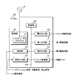
- FIG. 1 is a block diagram showing a main configuration of the power supply system 1 according to the first embodiment.
- the power supply system 1 is mounted on the vehicle C.
- the power supply system 1 includes a power supply control device 10, a DC power supply 11, a first load E, and a second load F.
- the DC power supply 11 is, for example, a battery.
- the power supply control device 10 is separately connected to the positive electrode of the DC power supply 11, one end of the first load E, and one end of the second load F.
- the negative electrode of the DC power supply 11, the other end of the first load E, and the other end of the second load F are grounded. Grounding is achieved, for example, by connecting the vehicle C to the body.
- the DC power supply 11 supplies electric power to the first load E and the second load F via the power supply control device 10.
- Each of the first load E and the second load F is an electric device.
- the first load E operates.
- the first load E stops the operation.
- the second load F operates.
- the power supply control device 10 separately controls the power supply to the first load E and the second load F.
- the power supply control device 10 has a first controller G and a second controller H.
- the first controller G has a first switch 20.
- the second controller H has a circuit switch 30 and a second switch 31.
- Each of the first switch 20, the circuit switch 30, and the second switch 31 is an N-channel type FET (Field Effect Transistor).
- the source of the first switch 20 is connected to one end of the first load E.
- the drain of the first switch 20 is connected to the source of the circuit switch 30.
- the drain of the circuit switch 30 is connected to the positive electrode of the DC power supply 11.
- the source of the second switch 31 is connected to one end of the second load F.
- the drain of the second switch 31 is connected to the positive electrode of the DC power supply 11.
- the resistance value between the drain and the source is sufficiently small. Therefore, it is possible for current to flow through the drain and source.
- the resistance value is sufficiently large. Therefore, no current flows through the drain and the source.
- An ignition signal indicating the state of the ignition switch of the vehicle C is input to the second controller H. If the ignition switch of vehicle C is on, the ignition signal indicates that the ignition switch is on. If the ignition switch of vehicle C is off, the ignition signal indicates that the ignition switch is off.
- the second controller H switches the circuit switch 30 on when the ignition switch of the vehicle C is switched on.
- the second controller H switches the circuit switch 30 off when the ignition switch is switched off.
- the first controller G switches the first switch 20 on or off while the circuit switch 30 is on.
- the circuit switch 30 and the first switch 20 are arranged in the current path of the current flowing through the first load E.
- the first switch 20 functions as a load switch. When at least one of the first switch 20 and the circuit switch 30 is off, no current flows through the first load E. At this time, the power supply to the first load E is stopped.
- the second controller H instructs the first controller G to operate the power supply of the first load E while the circuit switch 30 is on.
- the second controller H instructs the first switch 20 to be turned on or off as an operation related to the feeding of the first load E.
- the first controller G switches the first switch 20 on or off according to the instruction of the second controller H. As a result, the power supply to the first load E is controlled.
- the second controller H functions as an indicator.
- the second controller H switches the second switch 31 on or off.
- the second switch 31 When the second switch 31 is switched from off to on, current flows from the positive electrode of the DC power supply 11 in the order of the second switch 31 and the second load F. As a result, electric power is supplied to the second load F.
- the second controller H controls the power supply to the second load F by switching the second switch 31 on or off.
- the current value of the current flowing through the first switch 20 and the first load E will be referred to as a load current value.
- Analog current value information indicating the load current value is input to the second controller H.
- the operation signal and the stop signal are input to the second controller H.
- the operation signal indicates a load to be operated in the first load E and the second load F.
- the stop signal indicates a load for stopping the operation in the first load E and the second load F.
- the second controller H instructs the first controller G to turn on the first switch 20 when an operation signal indicating the first load E is input.
- the second controller H notifies the occurrence of an off failure when the load current value is equal to or less than the current threshold value even though the first switch 20 is instructed to turn on.
- the second controller H performs notification by outputting a notification signal indicating the occurrence of an off failure.
- the current threshold is a constant value and is preset.
- the current threshold is zero A or a positive current value near zero A.
- the off failure is a phenomenon in which the load current value is equal to or less than the current threshold value even though the first switch 20 is instructed to be turned on.
- the second controller H instructs the first controller G to turn off the first switch 20 when a stop signal indicating the first load E is input.
- the second controller H notifies the occurrence of an on failure when the load current value exceeds the current threshold value even though the first switch 20 is instructed to be turned off.
- the second controller H performs notification by outputting a notification signal indicating the occurrence of an on-failure.
- the on failure is a phenomenon in which the load current value exceeds the current threshold value even though the first switch 20 is instructed to be turned off.
- the second controller H switches the circuit switch 30 to off when an on failure occurs in the first switch 20. As a result, the power supply to the first load E is stopped.
- the first load E is an electric device that does not interfere with the operation of the vehicle C even when the operation is always stopped.
- the first load E is, for example, a music player.
- the second controller H switches the second switch 31 on when the operation signal indicates the second load F.
- the second controller H switches the second switch 31 off when the stop signal indicates the second load F.
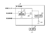
- FIG. 2 is a block diagram showing a main configuration of the first controller G.
- the first controller G has a first drive circuit 21, a current output unit 22, and a resistor 23 in addition to the first switch 20.
- the drain and the source of the first switch 20 are connected to the source of the circuit switch 30 and one end of the first load E, respectively.
- the drain and the gate of the first switch 20 are separately connected to the first drive circuit 21.
- the first drive circuit 21 is further connected to the second controller H.
- the first drive circuit 21 is grounded.
- the drain of the first switch 20 is connected to the current output unit 22.
- the current output unit 22 is further connected to one end of the resistor 23.
- the other end of the resistor 23 is grounded.
- the connection node between the current output unit 22 and the resistor 23 is connected to the second controller H.
- the circuit switch 30 When the circuit switch 30 is switched on, the current flows from the positive electrode of the DC power supply 11 in the order of the circuit switch 30 and the first drive circuit 21. As a result, electric power is supplied to the first drive circuit 21 via the circuit switch 30. When the circuit switch 30 is switched off, the power supply to the first drive circuit 21 is stopped. While power is being supplied to the first drive circuit 21, the first drive circuit 21 operates. When the power supply to the first drive circuit 21 is stopped, the operation of the first drive circuit 21 is stopped.
- the first switch 20 when the voltage value of the gate whose reference potential is the potential of the source is a constant voltage value or more, the first switch 20 is on. In the first switch 20, when the voltage value of the gate whose reference potential is the potential of the source is less than a constant voltage value, the first switch 20 is off.
- the second controller H outputs a high level voltage and a low level voltage to the first drive circuit 21.
- the first drive circuit 21 is the first switch.
- the voltage value of the gate whose reference potential is the ground potential is increased.
- the voltage value of the gate whose reference potential is the potential of the source rises to a voltage value equal to or higher than a constant voltage value.
- the first switch 20 is switched on.
- the reference potential of the first drive circuit 21 is the ground potential in the first switch 20. Decrease the voltage value of the gate. As a result, in the first switch 20, the voltage value of the gate whose reference potential is the potential of the source drops to a voltage value less than a constant voltage value. As a result, the first switch 20 is switched off.
- the first drive circuit 21 switches the first switch 20 on or off by adjusting the voltage value of the gate whose reference potential is the potential of the source.
- the first drive circuit 21 functions as a switching circuit.
- the second controller H outputs a high level voltage to the first drive circuit 21 to instruct the first switch 20 to be switched on.
- the second controller H instructs the first switch 20 to switch off by outputting a low level voltage to the first drive circuit 21.
- the first drive circuit 21 when power is not supplied to the first drive circuit 21, the first drive circuit 21 has stopped operating.
- the first drive circuit 21 when the first drive circuit 21 is stopped, in the first switch 20, the voltage value of the gate whose reference potential is the potential of the source is less than a constant voltage value. Therefore, the first switch 20 is off.
- the current output unit 22 draws a current from the drain of the first switch 20, and outputs the drawn current to the resistor 23.
- the current value of the current drawn by the current output unit 22 is represented by (load current value) / (predetermined number).
- the load current value is the current value of the current flowing through the first switch 20 and the first load E.
- the predetermined number is a constant value, for example, 1000.
- the voltage value between both ends of the resistor 23 is output to the second controller H as analog current value information.
- the current value information is represented by (load current value) and (resistance value of resistor 23) / (predetermined number). " ⁇ " Represents the product. Since the resistance value and the predetermined number of the resistors 23 are constant values, the current value information indicates the load current value.
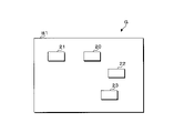
- FIG. 3 is a plan view of the first controller G.
- the first controller G is formed on the first substrate B1.
- a first switch 20, a first drive circuit 21, a current output unit 22, and a resistor 23 are arranged on the first substrate B1.
- one or a plurality of elements constituting the first switch 20, the first drive circuit 21, the current output unit 22, and the resistor 23 are arranged on the first substrate B1.
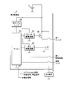
- FIG. 4 is a block diagram showing a main configuration of the second controller H.
- the second controller H has a switch drive circuit 32, a second drive circuit 33, a microcomputer (hereinafter referred to as a microcomputer) 34, and a second regulator 35 in addition to the circuit switch 30 and the second switch 31.
- a microcomputer hereinafter referred to as a microcomputer
- the drains of the circuit switch 30 and the second switch 31 are connected to the positive electrode of the DC power supply 11.
- the source of the circuit switch 30 is connected to the drain of the first switch 20 included in the first controller G.
- the source of the second switch 31 is connected to one end of the second load F.
- the gates of the circuit switch 30 and the second switch 31 are connected to the switch drive circuit 32 and the second drive circuit 33, respectively.
- Each of the switch drive circuit 32 and the second drive circuit 33 is connected to the microcomputer 34.
- the switch drive circuit 32, the second drive circuit 33, and the microcomputer 34 are each grounded.
- the drains of the circuit switch 30 and the second switch 31 are connected to the switch drive circuit 32, the second drive circuit 33, and the second regulator 35.
- the second regulator 35 is further connected to the microcomputer 34.
- the voltage between both ends of the DC power supply 11 is input to the second regulator 35.
- the second regulator 35 steps down the voltage between both ends of the DC power supply 11 to a constant voltage, and outputs the stepped-down voltage to the microcomputer 34.
- current flows from the positive electrode of the DC power supply 11 in the order of the second regulator 35 and the microcomputer 34.
- electric power is supplied to the microcomputer 34.
- the current flows from the positive electrode of the DC power supply 11 to the switch drive circuit 32 and the second drive circuit 33.
- electric power is supplied to the switch drive circuit 32 and the second drive circuit 33.
- the circuit switch 30 when the voltage value of the gate whose reference potential is the potential of the source is a constant voltage value or more, the circuit switch 30 is on. In the circuit switch 30, when the voltage value of the gate whose reference potential is the potential of the source is less than a constant voltage value, the circuit switch 30 is off.
- the microcomputer 34 outputs a high level voltage and a low level voltage to the switch drive circuit 32.
- the switch drive circuit 32 When the voltage output to the switch drive circuit 32 is switched from the low level voltage to the high level voltage, the switch drive circuit 32 raises the voltage value of the gate whose reference potential is the ground potential in the circuit switch 30. As a result, in the circuit switch 30, the voltage value of the gate whose reference potential is the potential of the source rises to a voltage equal to or higher than a constant voltage value. As a result, the circuit switch 30 is switched on.
- the switch drive circuit 32 When the voltage output to the switch drive circuit 32 is switched from the high level voltage to the low level voltage, the switch drive circuit 32 lowers the voltage value of the gate whose reference potential is the ground potential in the circuit switch 30. As a result, in the circuit switch 30, the voltage value of the gate whose reference potential is the potential of the source drops to a voltage lower than a constant voltage value. As a result, the circuit switch 30 is switched off.
- the switch drive circuit 32 switches the circuit switch 30 on or off by adjusting the voltage value of the gate whose reference potential is the potential of the source.
- the microcomputer 34 instructs the circuit switch 30 to be switched on by outputting a high level voltage to the switch drive circuit 32.
- the microcomputer 34 outputs a low level voltage to the switch drive circuit 32 to instruct the circuit switch 30 to be switched off.
- the second switch 31 when the voltage value of the gate whose reference potential is the potential of the source is a constant voltage value or more, the second switch 31 is on. In the second switch 31, when the voltage value of the gate whose reference potential is the potential of the source is less than a constant voltage value, the second switch 31 is off.
- the microcomputer 34 outputs a high level voltage and a low level voltage to the second drive circuit 33.
- the second drive circuit 33 switches the second switch 31 on or off according to the voltage output to the second drive circuit 33. This switching is the same as the switching of the circuit switch 30 performed by the switch drive circuit 32 according to the voltage output to the switch drive circuit 32. In the description of the switching of the circuit switch 30, the switching of the second switch 31 can be described by replacing the circuit switch 30 and the switch drive circuit 32 with the second switch 31 and the second drive circuit 33, respectively.
- the second drive circuit 33 switches the second switch 31 on or off by adjusting the voltage value of the gate whose reference potential is the potential of the source.
- the microcomputer 34 outputs a high level voltage to the second drive circuit 33 to instruct the second switch 31 to be switched on.
- the microcomputer 34 outputs a low level voltage to the second drive circuit 33 to instruct the second switch 31 to be switched off.
- the microcomputer 34 outputs a high level voltage or a low level voltage to the first drive circuit 21.
- the microcomputer 34 instructs the first switch 20 to be switched on by outputting a high level voltage to the first drive circuit 21.
- the microcomputer 34 outputs a low level voltage to the first drive circuit 21 to instruct the first switch 20 to be switched off.
- Analog current value information is input from the second controller H to the microcomputer 34.
- An ignition signal is input to the microcomputer 34.
- the microcomputer 34 When the ignition switch of the vehicle C is switched on, the microcomputer 34 outputs a high level voltage to the switch drive circuit 32 to instruct the circuit switch 30 to be switched on.
- the microcomputer 34 When the ignition switch of the vehicle C is switched off, the microcomputer 34 outputs a low level voltage to the switch drive circuit 32 to instruct the circuit switch 30 to switch off.
- the microcomputer 34 instructs the first switch 20 to be turned on or off while the circuit switch 30 is on.
- the microcomputer 34 turns on the first switch 20 by switching the voltage output to the first drive circuit 21 of the first controller G to a high level voltage. Instruct to switch to.
- the microcomputer 34 instructs the first switch 20 to switch off by switching the voltage output to the first drive circuit 21 to a low level voltage. ..
- the microcomputer 34 notifies the occurrence of an off failure when the load current threshold value is equal to or less than the current threshold value even though the first switch 20 is instructed to switch on. Specifically, the microcomputer 34 notifies the off failure by outputting a notification signal indicating the occurrence of the off failure. When the load current value exceeds the current threshold value even though the microcomputer 34 has instructed to switch the first switch 20 to off, the microcomputer 34 notifies the occurrence of an on failure. Specifically, the microcomputer 34 notifies the on-failure by outputting a notification signal indicating the occurrence of the on-failure.
- the first drive circuit 21 switches the first switch 20 on.
- the first drive circuit 21 switches the first switch 20 off.
- the high level voltage is higher than the low level voltage.
- the connection line connecting the first drive circuit 21 and the microcomputer 34 is grounded, the voltage output to the first drive circuit 21 is fixed to the low level voltage.
- an off failure occurs.
- the circuit switch 30 is on and the connection line connecting the first drive circuit 21 and the microcomputer 34 is connected to the connection line connecting the first switch 20 and the circuit switch 30, the first drive is performed.
- the voltage output to the circuit 21 is fixed to the high level voltage. As a result, on-failure occurs.
- the microcomputer 34 When the operation signal indicates the second load F, the microcomputer 34 outputs a high level voltage to the second drive circuit 33 to instruct the second switch 31 to be switched on. When the stop signal indicates the second load F, the microcomputer 34 outputs a low level voltage to the second drive circuit 33 to instruct the second switch 31 to be switched off.
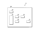
- FIG. 5 is a plan view of the second controller H.
- the second controller H is formed on a second substrate B2 different from the first substrate B1.
- a circuit switch 30, a second switch 31, a switch drive circuit 32, a second drive circuit 33, a microcomputer 34, and a second regulator 35 are arranged on the second substrate B2.
- one or more elements constituting the circuit switch 30, the second switch 31, the switch drive circuit 32, the second drive circuit 33, the microcomputer 34, and the second regulator 35 are arranged on the second substrate B2. There is.
- FIG. 6 is a block diagram showing a configuration of a main part of the microcomputer 34.
- the microcomputer 34 has a voltage output unit 40, a first output unit T, a second output unit 41, an A / D conversion unit U, a signal input unit 42, a notification unit 43, a storage unit 44, and a control unit 45. These are connected to the internal bus 46.
- the voltage output unit 40, the first output unit T, and the second output unit 41 are each further connected to the switch drive circuit 32, the first drive circuit 21, and the second drive circuit 33.
- the A / D conversion unit U is further connected to a connection node between the current output unit 22 and the resistor 23 of the first controller G.
- the voltage output unit 40 outputs a high level voltage or a low level voltage to the switch drive circuit 32 according to the instruction of the control unit 45.
- the control unit 45 instructs the switch drive circuit 32 to switch the circuit switch 30 on by causing the voltage output unit 40 to output a high level voltage.
- the control unit 45 instructs the switch drive circuit 32 to switch the circuit switch 30 to off by causing the voltage output unit 40 to output a low level voltage.
- the first output unit T outputs a high level voltage or a low level voltage to the first drive circuit 21 according to the instruction of the control unit 45.
- the control unit 45 instructs the first drive circuit 21 to switch the first switch 20 on by causing the first drive circuit 21 to output a high level voltage.
- the control unit 45 instructs the first drive circuit 21 to switch the first switch 20 to off by causing the first output unit T to output a low level voltage.
- the second output unit 41 outputs a high level voltage or a low level voltage to the second drive circuit 33 according to the instruction of the control unit 45.
- the control unit 45 instructs the second drive circuit 33 to switch the second switch 31 on by causing the second drive circuit 33 to output a high level voltage.
- the control unit 45 instructs the second drive circuit 33 to switch the second switch 31 to off by causing the second output unit 41 to output a low level voltage.
- Analog current value information is input from the connection node of the first controller G to the A / D conversion unit U.
- the A / D conversion unit U converts the input analog current value information into digital current value information.
- the control unit 45 acquires digital current value information from the A / D conversion unit U.
- the ignition signal, the operation signal and the stop signal are input to the signal input unit 42.
- the notification unit 43 performs notification according to the instruction of the control unit 45.
- the notification unit 43 realizes notification by outputting a notification signal indicating the occurrence of an off failure or an on failure.
- the storage unit 44 is a non-volatile memory.
- the computer program P is stored in the storage unit 44.
- the control unit 45 has a processing element for executing processing, for example, a CPU (Central Processing Unit).
- the control unit 45 functions as a processing unit.
- the processing element (computer) of the control unit 45 executes the switch control process, the first power supply control process, the second power supply control process, and the like in parallel by executing the computer program P.
- the switch control process is a process of switching the circuit switch 30 on or off.
- the first power supply control process is a process for controlling power supply to the first load E.
- the second power supply control process is a process for controlling the power supply to the second load F.
- the computer program P may be stored in the non-temporary storage medium A so that the processing element of the control unit 45 can read it.
- the computer program P read from the storage medium A by a reading device (not shown) is written in the storage unit 44.
- the storage medium A is an optical disk, a flexible disk, a magnetic disk, a magnetic disk disk, a semiconductor memory, or the like.
- the optical disk is a CD (Compact Disc) -ROM (Read Only Memory), a DVD (Digital Versatile Disc) -ROM, or a BD (Blu-ray (registered trademark) Disc).
- the magnetic disk is, for example, a hard disk.
- the computer program P may be downloaded from an external device (not shown) connected to a communication network (not shown), and the downloaded computer program P may be written in the storage unit 44.
- the number of processing elements included in the control unit 45 is not limited to 1, and may be 2 or more. When the number of processing elements included in the control unit 45 is two or more, a plurality of processing elements may cooperate to execute a switch control process, a first power supply control process, a second power supply control process, and the like.
- the value of the failure flag is stored in the storage unit 44.
- the value of the failure flag is zero or one and is changed by the control unit 45.
- a failure flag value of zero means that neither on-failure nor off-failure has occurred.
- the value of the failure flag is 1, it means that at least one of the off failure and the on failure has occurred.
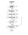
- FIG. 7 is a flowchart showing the procedure of the switch control process.
- the switch control process is executed with the circuit switch 30 turned off.
- the control unit 45 first determines whether or not the value of the failure flag is zero (step S1).
- S1: YES the value of the failure flag is zero
- step S2: NO the control unit 45 executes step S2 again and waits until the ignition switch is switched on.
- control unit 45 determines whether or not the ignition switch of the vehicle C has been switched off based on the ignition signal input to the signal input unit 42 (step S4).
- control unit 45 determines whether or not the value of the failure flag has been changed to 1 (step S5). The value of the failure flag is changed in the first power supply control process.
- step S4 When the control unit 45 determines that the value of the failure flag has not been changed to 1 (S5: NO), the control unit 45 executes step S4 again, and the ignition switch is switched off or the value of the failure flag is 1. Wait until it changes to.
- the control unit 45 determines that the ignition switch has been switched off (S4: YES) or determines that the value of the failure flag has been changed to 1 (S5: YES)
- the voltage output unit 40 has a low level.
- the switch drive circuit 32 By outputting a voltage, the switch drive circuit 32 is instructed to switch the circuit switch 30 to off (step S6). As a result, the switch drive circuit 32 switches the circuit switch 30 off.
- the control unit 45 ends the switch control process when it is determined that the value of the failure flag is not zero (S1: NO) or after step S6 is executed. After finishing the switch control process, the control unit 45 executes the switch control process again.
- the circuit switch 30 when the value of the failure flag is 1, the circuit switch 30 is kept off. When the value of the failure flag is zero and the ignition switch is switched on, the circuit switch 30 is switched on. After the circuit switch 30 is switched on, if the ignition switch is switched off or the value of the failure flag is changed to 1, the circuit switch 30 is switched off.
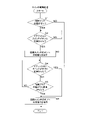
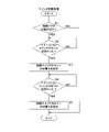
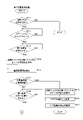
- First power supply control process> 8 and 9 are flowcharts showing the procedure of the first power supply control process.
- the first power supply control process is executed in a state where the first switch 20 is off.
- the control unit 45 first determines whether or not the value of the failure flag is zero (step S11).
- the control unit 45 determines that the value of the failure flag is not zero (S11: NO)
- the control unit 45 ends the first power supply control process.
- the control unit 45 determines whether or not to operate the first load E (step S12).
- step S12 when the operation signal indicating the first load E is input to the signal input unit 42, the control unit 45 determines that the first load E is operated. When the operation signal indicating the first load E is not input to the signal input unit 42, the control unit 45 determines that the first load E is not operated.
- step S12 When the control unit 45 determines that the first load E is not activated (S12: NO), the control unit 45 executes step S12 again and waits until the operation signal indicating the first load E is input to the signal input unit 42.
- the control unit 45 determines that the first load E is to be operated (S12: YES)
- the control unit 45 causes the first drive circuit 21 to turn on the first switch 20 by outputting the high level voltage to the first output unit T. Is instructed to be switched (step S13).
- step S14 acquires current value information from the A / D conversion unit U (step S14), and determines whether or not the load current value indicated by the acquired current value information is equal to or less than the current threshold value (step). S15).
- control unit 45 determines that the load current value is equal to or less than the current threshold value (S15: YES)
- the control unit 45 changes the flag value to 1 (step S16), and notifies the notification unit 43 of the occurrence of an off failure (step).
- the notification unit 43 performs notification by outputting a notification signal indicating the occurrence of an off failure.
- the control unit 45 ends the first power supply control process.
- step S18 when the control unit 45 determines that the load current value exceeds the current threshold value (S15: NO), the control unit 45 determines whether or not to stop the operation of the first load E (step S18).
- step S18 when the stop signal indicating the first load E is input to the signal input unit 42, the control unit 45 determines that the operation of the first load E is stopped.
- the stop signal indicating the first load E is not input to the signal input unit 42, the control unit 45 determines that the operation of the first load E is not stopped.
- the control unit 45 executes step S18 again and waits until a stop signal indicating the first load E is input to the signal input unit 42. do.
- the control unit 45 determines that the operation of the first load E is stopped (S18: YES), the control unit 45 instructs the first output unit T to switch the first switch 20 to off by outputting a low level voltage. (Step S19).
- the control unit 45 acquires current value information from the A / D conversion unit U (step S20), and determines whether or not the load current value indicated by the acquired current value information exceeds the current threshold value (step). S21).
- the control unit 45 determines that the load current value exceeds the current threshold value (S21: YES)
- the control unit 45 changes the flag value to 1 (step S22), and notifies the notification unit 43 of the occurrence of an on-failure (step S22).
- Step S23 As described above, the notification unit 43 performs notification by outputting a notification signal indicating the occurrence of an on-failure.
- the control unit 45 ends the first power supply control process when it is determined that the load current value is equal to or less than the current threshold value (S21: NO) or after step S23 is executed.
- the control unit 45 ends the first power supply control process after finishing the first power supply control process. After finishing the first power supply control process, the control unit 45 executes the first power supply control process again. As described above, when the value of the flag is changed to 1, the switch control process is instructed to switch the circuit switch 30 to off.
- the second power supply control process is executed in a state where the second switch 31 is off.
- the control unit 45 first determines whether or not to operate the second load F. When the operation signal indicating the second load F is input to the signal input unit 42, the control unit 45 determines that the second load F is operated. When the operation signal indicating the second load F is not input to the signal input unit 42, the control unit 45 determines that the second load F is not operated. When the control unit 45 determines that the second load F is not operated, the control unit 45 waits until an operation signal indicating the second load F is input to the signal input unit 42.
- control unit 45 determines that the second load F is to be operated, the control unit 45 instructs the second drive circuit 33 to switch the second switch 31 on by outputting the high level voltage to the second output unit 41. .. As a result, the second switch 31 is switched on, and power is supplied to the second load F.
- the control unit 45 After instructing the second drive circuit 33 to switch the second switch 31 on, the control unit 45 determines whether or not to stop the operation of the second load F. When the stop signal indicating the second load F is input to the signal input unit 42, the control unit 45 determines that the operation of the second load F is activated. When the stop signal indicating the second load F is not input to the signal input unit 42, the control unit 45 determines that the operation of the second load F is not stopped. When the control unit 45 determines that the operation of the second load F is not stopped, the control unit 45 waits until a stop signal indicating the second load F is input to the signal input unit 42.
- control unit 45 determines that the operation of the second load F is to be stopped, the control unit 45 outputs the low level voltage to the second output unit 41, so that the second drive circuit 33 switches the second switch 31 to off. Instruct. As a result, the second switch 31 is switched off, and the power supply to the second load F is stopped. The control unit 45 instructs the second drive circuit 33 to switch the second switch 31 to off, and then ends the second power supply control process. After finishing the second power supply control process, the control unit 45 executes the second power supply control process again.
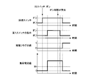
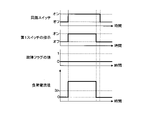
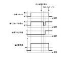
- FIG. 10 is a timing chart showing a first example of the operation of the power supply control device 10.
- FIG. 10 shows the transition of the state of the circuit switch 30, the transition of the instruction of the first switch 20, the transition of the value of the failure flag, and the transition of the load current value. Time is shown on the horizontal axis of these transitions.
- Examples of the instruction of the first switch 20 include an instruction of switching to on and an instruction of switching to off.
- the ignition switch is described as an IG switch. Is indicates the current threshold.
- the first example of the operation of the power supply control device 10 is an operation example when both the on failure and the off failure do not occur in the first switch 20.
- the switch drive circuit 32 switches the circuit switch 30 on.
- the switch drive circuit 32 switches the circuit switch 30 off.
- the value of the failure flag is zero.
- the load current value is zero A and is equal to or less than the current threshold value Is.
- Each of the operation signal and the stop signal is input to the signal input unit 42 while the ignition switch is on. Therefore, the control unit 45 instructs the first drive circuit 21 to switch the first switch 20 on or off while the circuit switch 30 is on.
- the control unit 45 instructs the first drive circuit 21 to switch the first switch 20 to ON.
- the first drive circuit 21 switches the first switch 20 on.
- the load current value exceeds the current threshold value Is, and the first load E operates.
- the control unit 45 instructs the first drive circuit 21 to switch the first switch 20 to off.
- the first drive circuit 21 switches the first switch 20 off.
- the load current value drops to zero A, and the first load E stops operating.
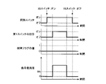
- FIG. 11 is a timing chart showing a second example of the operation of the power supply control device 10.
- FIG. 11 shows the transition of the state of the circuit switch 30, the transition of the instruction of the first switch 20, the transition of the value of the failure flag, and the transition of the load current value, as in FIG. Time is shown on the horizontal axis of these transitions.
- the IG switch is an ignition switch. Is indicates the current threshold.
- the second example of the operation of the power supply control device 10 is an operation example when an on failure occurs in the first switch 20.
- the switch drive circuit 32 switches the circuit switch 30 on.
- the value of the failure flag is zero.
- the load current value is zero A and is equal to or less than the current threshold value Is.
- the control unit 45 instructs the first drive circuit 21 to switch the first switch 20 on or off while the circuit switch 30 is on.
- the control unit 45 instructs the first drive circuit 21 to switch the first switch 20 to ON.
- the first drive circuit 21 switches the first switch 20 on.
- the first load E operates, and the load current value exceeds the current threshold value Is.
- the control unit 45 instructs the first drive circuit 21 to switch the first switch 20 to off.
- the load current value does not drop to a value equal to or less than the current threshold value Is.
- the control unit 45 detects the occurrence of an on-failure because the load current value exceeds the current threshold value Is even though the first switch 20 is instructed to be switched off.
- the flag value is changed to 1 in the first power supply control process, and the switch drive circuit 32 is instructed to switch the circuit switch 30 to off in the switch control process.
- the circuit switch 30 is switched off.
- the load current value drops to zero A, and the operation of the first load E stops.
- the first controller G and the second controller H are formed on the first substrate B1 and the second substrate B2, respectively. Therefore, the first controller G can be easily changed according to the first load E. By combining various first controllers G with the common second controller H, it is possible to realize a configuration corresponding to the first load E that controls the operation. Further, when an on failure occurs in the first switch 20, the power supply to the first load E can be stopped by switching the circuit switch 30 of the second controller H to off.
- the switch drive circuit 32 can switch the circuit switch 30 off to stop the power supply to the first drive circuit 21 and the current output unit 22 of the first controller G.
- the circuit switch 30 is switched off. As a result, electric power is efficiently consumed in the first drive circuit 21 and the current output unit 22.
- FIG. 12 is a flowchart showing the procedure of the switch control process in the second embodiment.
- the switch control process in the second embodiment is executed in a state where the circuit switch 30 is off, as in the switch control process in the first embodiment.
- a part of the switch control process in the second embodiment is the same as a part of the switch control process in the first embodiment. Therefore, in the switch control process in the second embodiment, detailed description of steps S1 to S4 and S6, which are common to the switch control process in the first embodiment, will be omitted.
- step S4 When the control unit 45 determines that the ignition switch has not been switched off (S4: NO), the control unit 45 executes step S4 again and waits until the ignition switch is switched off. When the control unit 45 determines that the ignition switch has been switched off (S4: YES), the control unit 45 executes step S6. In step S6, the control unit 45 instructs the switch drive circuit 32 to switch the circuit switch 30 to off by causing the voltage output unit 40 to output a low level voltage.
- the switch drive circuit 32 switches the circuit switch 30 off when the ignition switch is switched off after the circuit switch 30 is switched on. Even if the value of the failure flag is changed to 1 while the circuit switch 30 is on, the switch drive circuit 32 does not switch the circuit switch 30 off.
- FIG. 13 is a flowchart showing the procedure of the first power supply control process.
- the first power supply control process in the second embodiment is executed in a state where the first switch 20 is off, as in the first embodiment.
- the control unit 45 similarly executes steps S11 to S23 of the first power supply control process in the first embodiment. Therefore, detailed description of steps S11 to S23 will be omitted.
- the control unit 45 executes two processes in addition to steps S11 to S23.
- the control unit 45 executes step S15 in a state in which the switching of the first switch 20 to on is instructed.
- the control unit 45 determines that the load current value is equal to or less than the current threshold value (S15: YES)
- the control unit 45 instructs the first output unit T to switch the first switch 20 to off by outputting the low level voltage. (Step S31).
- step S15 When the load current value is equal to or less than the current threshold value at the time when step S15 is executed, it means that an off failure has occurred in the first switch 20.
- the control unit 45 determines that the load current value is equal to or less than the current threshold value, the first drive circuit 21 is instructed to switch the first switch 20 on. In the event of an off failure, the control unit 45 instructs the first switch 20 to switch off in order to keep the first switch 20 off until the ignition switch is switched off.
- the control unit 45 executes step S16 after executing step S31. In step S16, the value of the flag is changed to 1.
- control unit 45 executes step S21 in a state in which the switching of the first switch 20 to off is instructed.
- the control unit 45 determines that the load current value exceeds the current threshold value (S21: YES)
- the control unit 45 switches the first switch 20 to ON by causing the first output unit T to output a high level voltage. Instruct (step S32).
- step S21 When the load current value exceeds the current threshold value at the time when step S21 is executed, it means that an on-failure has occurred in the first switch 20.
- the control unit 45 determines that the load current value exceeds the current threshold value, the first drive circuit 21 is instructed to switch the first switch 20 to off. In the event of an on failure, the control unit 45 instructs the first switch 20 to switch on in order to keep the first switch 20 on until the ignition switch is switched off.
- step S22 the value of the flag is changed to 1.
- FIG. 14 is a timing chart showing an operation example of the power supply control device 10.
- FIG. 14 shows an operation example when an on-failure occurs in the first switch 20. Therefore, FIG. 14 corresponds to FIG. FIG. 14, as in FIG. 11, shows the transition of the state of the circuit switch 30, the transition of the instruction of the first switch 20, the transition of the value of the failure flag, and the transition of the load current value.
- the IG switch is an ignition switch. Is indicates the current threshold.
- the switch drive circuit 32 switches the circuit switch 30 on.
- the value of the failure flag is zero.
- the load current value is zero A and is equal to or less than the current threshold value Is.
- the control unit 45 instructs the first drive circuit 21 to switch the first switch 20 on or off while the circuit switch 30 is on.
- the control unit 45 instructs the first drive circuit 21 to switch the first switch 20 to ON.
- the first drive circuit 21 switches the first switch 20 on.
- the first load E operates, and the load current value exceeds the current threshold value Is.
- the control unit 45 instructs the first drive circuit 21 to switch the first switch 20 to off.
- the load current value does not drop to a value equal to or less than the current threshold value Is.
- the control unit 45 detects the occurrence of an on-failure because the load current value exceeds the current threshold value Is even though the first switch 20 is instructed to be switched off.
- the control unit 45 detects an on failure, it instructs the first drive circuit 21 to switch the first switch 20 to on in the first power supply control process, and changes the flag value to 1.
- the control unit 45 instructs the switch drive circuit 32 to switch the circuit switch 30 to off in the switch control process. As a result, the circuit switch 30 is switched off. As a result, the load current value drops to zero A, and the operation of the first load E stops.
- the first load E in the second embodiment is an electric device that is required to continue the operation when the operation cannot be performed again.
- the first load E in the second embodiment is, for example, a headlight.
- the ignition switch is switched off, that is, when the operation of the vehicle C is completed, the operation of the first load E is stopped.
- the circuit switch 30 is switched on when the ignition switch of the vehicle C is switched on.
- the timing at which the circuit switch 30 is switched on is not limited to the timing at which the ignition switch is switched on.
- the differences between the third embodiment and the first embodiment will be described.
- Other configurations other than the configurations described later are common to the first embodiment. Therefore, the same reference reference numerals as those in the first embodiment are assigned to the components common to the first embodiment, and the description of the components will be omitted.
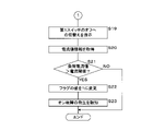
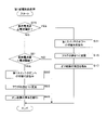
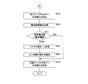
- First power supply control process> 15 and 16 are flowcharts showing the procedure of the first power supply control process.
- the first power supply control process in the third embodiment is executed in a state where the first switch 20 is off, as in the first embodiment.
- a part of the first power supply control process in the third embodiment is common with a part of the first power supply control process in the first embodiment. Therefore, in the first power supply control process in the third embodiment, the description of steps S11, S12, S14 to S23, which are common to the first power supply control process in the first embodiment, will be omitted.
- step S41 determines whether or not the ignition switch of the vehicle C is on based on the ignition signal input to the signal input unit 42. Determination (step S41).
- the control unit 45 determines that the ignition switch is not on (S41: NO)
- the control unit 45 executes step S41 again and waits until the ignition switch is switched on.
- the control unit 45 determines that the ignition switch is on (S41: YES)
- the control unit 45 executes step S12.
- Step S42 When the control unit 45 determines that the first load E is to be operated (S12: YES), the control unit 45 instructs the switch drive circuit 32 and the first drive circuit 21, respectively, to switch the circuit switch 30 and the first switch 20 on.
- the control unit 45 instructs the switch drive circuit 32 to switch the circuit switch 30 on by causing the voltage output unit 40 to output a high level voltage. Similar to the first embodiment, the control unit 45 instructs the first drive circuit 21 to switch the first switch 20 on by causing the first output unit T to output a high level voltage.
- the control unit 45 executes step S14 after executing step S42.
- the control unit 45 executes step S15 in a state in which the circuit switch 30 and the first switch 20 are instructed to be switched on.
- the control unit 45 determines that the load current value is equal to or less than the current threshold value (S15: YES)
- the control unit 45 switches the circuit switch 30 and the first switch 20 to off in the switch drive circuit 32 and the first drive circuit 21, respectively.
- Step S43 The control unit 45 instructs the switch drive circuit 32 to switch the circuit switch 30 to off by causing the voltage output unit 40 to output a low level voltage.
- the control unit 45 instructs the first drive circuit 21 to switch the first switch 20 to off by causing the first output unit T to output a low level voltage.
- the control unit 45 executes step S16 after executing step S43.
- the control unit 45 executes step S21 in a state in which the switching of the first switch 20 to off is instructed.
- the control unit 45 determines that the load current value is equal to or less than the current threshold value (S21: NO), or after executing step S23, the control unit 45 instructs the circuit switch 30 to be switched off (step S44). After executing step S44, the control unit 45 ends the first power supply control process.
- FIG. 17 is a timing chart showing a first example of the operation of the power supply control device 10.
- FIG. 17 corresponds to FIG.
- FIG. 17 shows the transition of the state of the circuit switch 30, the transition of the instruction of the first switch 20, the transition of the value of the failure flag, and the transition of the load current value, as in FIG.
- the IG switch is an ignition switch. Is indicates the current threshold.
- the first example of the operation of the power supply control device 10 is an operation example when both the on failure and the off failure do not occur in the first switch 20.
- the value of the failure flag is zero.
- the load current value is zero A and is equal to or less than the current threshold value Is.
- the control unit 45 switches the circuit switch 30 and the first switch 20 to ON in the switch drive circuit 32 and the first drive circuit 21, respectively. To instruct. As a result, the circuit switch 30 and the first switch 20 are switched on. As a result, current flows from the positive electrode of the DC power supply 11 in the order of the circuit switch 30, the first switch 20, and the first load E. The load current value exceeds the current threshold value Is, and the first load E operates.
- the control unit 45 instructs the first drive circuit 21 to switch the first switch 20 to off.
- the first drive circuit 21 switches the first switch 20 off.
- the load current value drops to zero A, and the first load E stops operating.
- the control unit 45 instructs the switch drive circuit 32 to switch the circuit switch 30 to off. As a result, the circuit switch 30 is switched off.
- FIG. 18 is a timing chart showing a second example of the operation of the power supply control device 10.
- FIG. 18 corresponds to FIG.
- FIG. 18 shows the transition of the state of the circuit switch 30, the transition of the instruction of the first switch 20, the transition of the value of the failure flag, and the transition of the load current value, as in FIG.
- the IG switch is an ignition switch. Is indicates the current threshold.
- the second example of the operation of the power supply control device 10 is an operation example when an on failure occurs in the first switch 20.
- the value of the failure flag is zero.
- the load current value is zero A and is equal to or less than the current threshold value Is.
- the control unit 45 when the operation signal indicating the first load E is input to the signal input unit 42, the control unit 45 has the circuit switch 30 and the first switch 20 in the switch drive circuit 32 and the first drive circuit 21, respectively. Instructs to switch on. As a result, the circuit switch 30 and the first switch 20 are switched on. As a result, the first load E operates, and the load current value exceeds the current threshold value Is.
- the control unit 45 instructs the first drive circuit 21 to switch the first switch 20 to off.
- the load current value does not drop to a value equal to or less than the current threshold value Is.
- the control unit 45 detects the occurrence of an on-failure because the load current value exceeds the current threshold value Is even though the first switch 20 is instructed to be switched off.
- the control unit 45 detects an on failure, it instructs the switch drive circuit 32 to switch the circuit switch 30 to off, and changes the value of the flag to 1.
- the load current value drops to zero A, and the operation of the first load E stops.
- the power supply control device 10 according to the third embodiment similarly exhibits the effect of the power supply control device 10 according to the first embodiment.
- FIG. 19 is a flowchart showing the procedure of the first power supply control process.
- the first power supply control process in the fourth embodiment is executed in a state where the first switch 20 is off, as in the third embodiment.
- the control unit 45 similarly executes steps S11, S12, S14 to S23, and S41 to S44 of the first power supply control process in the third embodiment. Therefore, detailed description of steps S11, S12, S14 to S23, and S41 to S44 will be omitted.
- the control unit 45 executes two processes in addition to steps S11, S12, S14 to S23, and S41 to S44.
- the control unit 45 executes step S21 in a state in which the switching of the first switch 20 to off is instructed.
- the control unit 45 determines that the load current value exceeds the current threshold value (S21: YES)
- the control unit 45 switches the first switch 20 to ON by causing the first output unit T to output a high level voltage. Instruct (step S51).
- step S51 the control unit 45 executes step S22.
- step S23 the control unit 45 determines whether or not the ignition switch of the vehicle C has been switched off based on the ignition signal input to the signal input unit 42 (step S52).
- step S52 determines that the ignition switch has not been switched off
- step S52 again and waits until the ignition switch is switched off.
- the control unit 45 executes step S44 when it is determined that the load current value is equal to or less than the current threshold value (S21: NO) or when it is determined that the ignition switch is switched off (S52: YES).
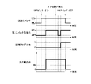
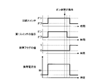
- FIG. 20 is a timing chart showing an operation example of the power supply control device 10.
- FIG. 20 shows an operation example when an on-failure occurs in the first switch 20. Therefore, FIG. 20 corresponds to FIG.
- FIG. 20 shows the transition of the state of the circuit switch 30, the transition of the instruction of the first switch 20, the transition of the value of the failure flag, and the transition of the load current value, as in FIG.
- the IG switch is an ignition switch. Is indicates the current threshold.
- the value of the failure flag is zero.
- the load current value is zero A and is equal to or less than the current threshold value Is.
- the control unit 45 receives the switch drive circuit 32 and the first drive circuit 21 respectively. Instructs the circuit switch 30 and the first switch 20 to be switched on. As a result, the circuit switch 30 and the first switch 20 are switched on. As a result, the first load E operates, and the load current value exceeds the current threshold value Is.
- the control unit 45 instructs the first drive circuit 21 to switch the first switch 20 to off.
- the load current value does not drop to a value equal to or less than the current threshold value Is.
- the control unit 45 detects the occurrence of an on-failure because the load current value exceeds the current threshold value Is even though the first switch 20 is instructed to be switched off.
- the control unit 45 detects an on failure, it instructs the first drive circuit 21 to switch the first switch 20 to on, and changes the value of the flag to 1.
- the control unit 45 waits until the ignition switch is switched on while the circuit switch 30 is kept on.
- the control unit 45 instructs the switch drive circuit 32 to switch the circuit switch 30 to off.
- the circuit switch 30 is switched off.
- the load current value drops to zero A, and the operation of the first load E stops.
- the first load E in the fourth embodiment is an electric device that is required to continue the operation when the operation cannot be performed again.
- the operation of the first load E is stopped when the ignition switch is switched off, that is, when the operation of the vehicle C is completed.
- the number of first loads E for which the power supply control device 10 controls the power supply is 1.
- the number of first loads E for which the power supply control device 10 controls power supply is not limited to one.
- the differences between the fifth embodiment and the first embodiment will be described.
- Other configurations other than the configurations described later are common to the first embodiment. Therefore, the same reference reference numerals as those in the first embodiment are assigned to the components common to the first embodiment, and the description of the components will be omitted.
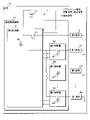
- FIG. 21 is a block diagram showing a main configuration of the power supply system 1 according to the fifth embodiment.
- the power supply system 1 according to the fifth embodiment includes a configuration other than the first load E among the components included in the power supply system 1 according to the first embodiment.
- the power supply system 1 in the fifth embodiment includes n first loads E1, E2, ..., En instead of the first load E.
- n is an integer of 2 or more.
- any integer that is 1 or more and n or less is represented by i. Therefore, i may be any integer belonging to the range of 1 or more and n or less.
- the power supply control device 10 is separately connected to one end of the first load Ei.
- the other end of the first load Ei is grounded.
- the DC power supply 11 supplies electric power to the first load Ei via the power supply control device 10.
- the power supply control device 10 separately controls the power supply to the n first loads E1, E2, ..., En and the second load F.
- the operation signal indicates a load to be operated in n first loads E1, E2, ..., En and a second load F.
- the stop signal indicates a load for stopping the operation among the n first loads E1, E2, ..., En and the second load F.
- the power supply control device 10 in the fifth embodiment has a component other than the first controller G among the components of the power supply control device 10 in the first embodiment.
- the power supply control device 10 in the fifth embodiment has n first controllers G1, G2, ..., Gn instead of the first controller G.
- the first controller Gi is configured in the same manner as the first controller G in the first embodiment. Therefore, the first controller Gi has a first switch 20.
- the source of the first switch 20 is connected to one end of the first load Ei.
- the drain of the first switch 20 is connected to the source of the circuit switch 30 included in the second controller H.
- Each of the first controllers G1, G2, ..., Gn is formed on n first substrates B1.
- the current flows from the positive electrode of the DC power supply 11 to the circuit switch 30, the first switch 20, and the first. It flows in the order of load Ei. As a result, electric power is supplied to the first load Ei.
- the circuit switch 30 and the first switch 20 are arranged in the current path of the current flowing through the first load Ei.
- the current flowing through the circuit switch 30 is divided into n currents. Each of these currents flows through n first loads E1, E2, ..., En.
- n first loads E1, E2, ..., En When at least one of the first switch 20 of the first controller Gi and the circuit switch 30 of the second controller H is off, no current flows through the first load Ei. At this time, the power supply to the first load Ei is stopped.
- the second controller H instructs the first controller Gi to operate the power supply of the first load Ei while the circuit switch 30 is on.
- the second controller H instructs the first switch 20 to be turned on or off as an operation related to the feeding of the first load Ei.
- the first controller Gi switches the first switch 20 on or off according to the instruction of the second controller H. As a result, the power supply to the first load Ei is controlled.
- the first controller Gi is configured in the same manner as the first controller G in the first embodiment.
- the operation performed by the second controller H with respect to the first controller Gi is the same as the operation performed by the second controller H with respect to the first controller G in the first embodiment.
- FIG. 22 is a block diagram showing a configuration of a main part of the microcomputer 34.
- the microcomputer 34 in the fifth embodiment has a component other than the first output unit T and the A / D conversion unit U among the components included in the microcomputer 34 in the first embodiment.
- the microcomputer 34 in the fifth embodiment has n first output units T1, T2, ..., Tn instead of the first output unit T.
- the microcomputer 34 in the fifth embodiment has n A / D conversion units U1, U2, ..., Un instead of the A / D conversion unit U.
- the first output unit Ti and the A / D conversion unit Ui are connected to the internal bus 46.
- the first output unit Ti is further connected to the first drive circuit 21 of the first controller Gi.
- the A / D conversion unit Ui is further connected to a connection node between the current output unit 22 and the resistor 23 of the first controller Gi.
- the first output unit Ti operates in the same manner as the first output unit T in the first embodiment. Therefore, the control unit 45 instructs the first output unit Ti to switch the first switch 20 of the first controller Gi on or off by outputting the high level voltage or the low level voltage.
- the A / D conversion unit Ui operates in the same manner as the A / D conversion unit Ui in the first embodiment. Therefore, the control unit 45 acquires the current value information from the A / D conversion unit Ui.
- the current value information acquired from the A / D conversion unit Ui indicates the load current value of the current flowing through the first switch 20 of the first controller Gi and the first load Ei.
- the processing element of the control unit 45 executes the switch control process, the n first power supply control processes, and the second power supply control process by executing the computer program P.
- the control unit 45 executes the switch control process and the second power supply control process in the same manner as in the first embodiment.
- the value of the failure flag is zero, it means that no on-failure or off-failure has occurred in all the first switches 20.
- the value of the failure flag is 1, it means that an on failure or an off failure has occurred in at least one of the n first switches 20.
- Each of the n first power supply control processes is a process for controlling the power supply to the n first loads E1, E2, ..., En.
- the control unit 45 executes each of the n first power supply control processes in the same manner as the first power supply control process in the first embodiment.
- the control unit 45 determines whether or not to operate the first load Ei based on whether or not an operation signal indicating the first load Ei is input.
- the control unit 45 determines whether or not to stop the operation of the first load Ei based on whether or not a stop signal indicating the first load Ei is input.
- the control unit 45 instructs the first switch 20 of the first controller Gi to be switched on or off.
- the control unit 45 acquires current value information from the A / D conversion unit Ui.
- the circuit switches 30 are arranged on the upstream side of the n first switches 20. By switching the circuit switch 30 off, it is possible to stop the power supply to the n first loads E1, E2, ..., En.
- the power supply control device 10 according to the fifth embodiment similarly exhibits the effect of the power supply control device 10 according to the first embodiment.
- the control unit 45 executes the switch control process and the second power supply control process in the same manner as in the second embodiment.
- the control unit 45 executes each of the n first power supply control processes in the same manner as the first power supply control process in the second embodiment.
- the control unit 45 determines whether or not to operate the first load Ei based on whether or not an operation signal indicating the first load Ei is input.
- the control unit 45 determines whether or not to stop the operation of the first load Ei based on whether or not a stop signal indicating the first load Ei is input.
- the control unit 45 instructs the first switch 20 of the first controller Gi to be switched on or off.
- the control unit 45 acquires current value information from the A / D conversion unit Ui.
- the control unit 45 keeps the circuit switch 30 on until the ignition switch is switched off. do.
- the n first loads E1, E2, ..., En include an electric device that is required to continue the operation when the operation cannot be performed again.
- the power supply control device 10 according to the sixth embodiment similarly exhibits the effect of the power supply control device 10 according to the fifth embodiment.
- the power supply system 1 does not have to include the second load F.
- the second controller H of the power supply control device 10 does not have the second switch 31 and the second drive circuit 33.
- the second switch 31 and the second drive circuit 33 are not arranged on the second substrate B2.
- the control unit 45 changes the value of the failure flag to 1 only when an on-failure occurs in at least one of the n first switches 20.
- the control unit 45 when the control unit 45 detects the occurrence of an on failure or an off failure and the ignition switch is switched off, the control unit 45 turns off the circuit switch 30. Instruct switching.
- the timing at which the control unit 45 instructs the circuit switch 30 to be switched off is not limited to the timing when the ignition switch is switched off, and may be the timing when the vehicle C has stopped traveling. Therefore, the timing at which the control unit 45 instructs the circuit switch 30 to be switched off may be the timing at which the vehicle C is parked.
- the control unit 45 can determine, for example, whether or not the vehicle C is parked based on the position of the shift lever of the vehicle C.
- the place where the current input end for supplying electric power is connected is not limited to the position on the downstream side of the circuit switch 30, and the position on the upstream side of the circuit switch 30. It may be. In this configuration, the DC power supply 11 always supplies power to the first drive circuit 21.
- connection line connecting the first drive circuit 21 and the microcomputer 34 When the connection line connecting the first drive circuit 21 and the microcomputer 34 is grounded, the voltage output to the first drive circuit 21 is fixed to the low level voltage. In this case, on-failure occurs in the above-mentioned configuration.
- connection line connecting the first drive circuit 21 and the microcomputer 34 When the connection line connecting the first drive circuit 21 and the microcomputer 34 is connected to the connection line connecting the first switch 20 and the circuit switch 30 while the circuit switch 30 is on, the first drive circuit 21 is connected.
- the output voltage is fixed at the high level voltage. In this case, in the above-mentioned configuration, an off failure occurs.
- the control unit 45 detects an on failure or an off failure of the second switch 31 based on the current value of the current flowing through the second switch 31, similarly to the first switch 20. May be good.
- each of the first switch 20, the circuit switch 30, and the second switch 31 may function as a switch, and is not limited to the N-channel type FET.
- Each of the first switch 20, the circuit switch 30, and the second switch 31 may be a P-channel type FET, a bipolar transistor, a relay contact, or the like.
- Power supply system 10 Power supply control device 11 DC power supply 20 First switch (load switch) 21 First drive circuit (switching circuit) 22 Current output unit 23 Resistance 30 Circuit switch 31 Second switch 32 Switch drive circuit 33 Second drive circuit 34 Microcomputer 35 Second regulator 40 Voltage output unit 41 Second output unit 42 Signal input unit 43 Notification unit 44 Storage unit 45 Control unit (Processing unit) 46 Internal bus A Storage medium B1 1st board B2 2nd board C Vehicle E, E1, E2, ..., En 1st load F 2nd load G, G1, G2, ..., Gn 1st controller ( Controller) H 2nd controller (indicator) P Computer program T, T1, T2, ..., Tn 1st output unit U, U1, U2, ..., Un A / D conversion unit
Landscapes
- Engineering & Computer Science (AREA)
- Mechanical Engineering (AREA)
- Power Engineering (AREA)
- Direct Current Feeding And Distribution (AREA)
- Charge And Discharge Circuits For Batteries Or The Like (AREA)
Priority Applications (2)
| Application Number | Priority Date | Filing Date | Title |
|---|---|---|---|
| CN202180076411.7A CN116490404A (zh) | 2020-11-17 | 2021-10-29 | 供电控制装置、供电控制方法及计算机程序 |
| US18/037,520 US20240051481A1 (en) | 2020-11-17 | 2021-10-29 | Power supply control device, power supply control method, and computer program |
Applications Claiming Priority (2)
| Application Number | Priority Date | Filing Date | Title |
|---|---|---|---|
| JP2020191092A JP7596736B2 (ja) | 2020-11-17 | 2020-11-17 | 給電制御装置、給電制御方法及びコンピュータプログラム |
| JP2020-191092 | 2020-11-17 |
Publications (1)
| Publication Number | Publication Date |
|---|---|
| WO2022107569A1 true WO2022107569A1 (ja) | 2022-05-27 |
Family
ID=81708720
Family Applications (1)
| Application Number | Title | Priority Date | Filing Date |
|---|---|---|---|
| PCT/JP2021/039936 Ceased WO2022107569A1 (ja) | 2020-11-17 | 2021-10-29 | 給電制御装置、給電制御方法及びコンピュータプログラム |
Country Status (4)
| Country | Link |
|---|---|
| US (1) | US20240051481A1 (enExample) |
| JP (1) | JP7596736B2 (enExample) |
| CN (1) | CN116490404A (enExample) |
| WO (1) | WO2022107569A1 (enExample) |
Families Citing this family (1)
| Publication number | Priority date | Publication date | Assignee | Title |
|---|---|---|---|---|
| GB202117975D0 (en) * | 2021-12-13 | 2022-01-26 | Continental Automotive Gmbh | Interface circuit, electronic control unit system, and methods of operating devices using an electronic control unit |
Citations (2)
| Publication number | Priority date | Publication date | Assignee | Title |
|---|---|---|---|---|
| JP2017188773A (ja) * | 2016-04-05 | 2017-10-12 | 株式会社オートネットワーク技術研究所 | 給電制御装置 |
| JP2019106624A (ja) * | 2017-12-12 | 2019-06-27 | 株式会社オートネットワーク技術研究所 | 給電制御装置及び給電制御方法 |
-
2020
- 2020-11-17 JP JP2020191092A patent/JP7596736B2/ja active Active
-
2021
- 2021-10-29 CN CN202180076411.7A patent/CN116490404A/zh active Pending
- 2021-10-29 US US18/037,520 patent/US20240051481A1/en active Pending
- 2021-10-29 WO PCT/JP2021/039936 patent/WO2022107569A1/ja not_active Ceased
Patent Citations (2)
| Publication number | Priority date | Publication date | Assignee | Title |
|---|---|---|---|---|
| JP2017188773A (ja) * | 2016-04-05 | 2017-10-12 | 株式会社オートネットワーク技術研究所 | 給電制御装置 |
| JP2019106624A (ja) * | 2017-12-12 | 2019-06-27 | 株式会社オートネットワーク技術研究所 | 給電制御装置及び給電制御方法 |
Also Published As
| Publication number | Publication date |
|---|---|
| JP2022080104A (ja) | 2022-05-27 |
| JP7596736B2 (ja) | 2024-12-10 |
| US20240051481A1 (en) | 2024-02-15 |
| CN116490404A (zh) | 2023-07-25 |
Similar Documents
| Publication | Publication Date | Title |
|---|---|---|
| JP7028355B2 (ja) | 制御装置、制御方法及びコンピュータプログラム | |
| JP5546524B2 (ja) | 車両のスタータモータ駆動回路 | |
| WO2022107569A1 (ja) | 給電制御装置、給電制御方法及びコンピュータプログラム | |
| US20220045502A1 (en) | Power distribution device, power distribution method, and computer program | |
| JP7404999B2 (ja) | 給電制御装置、溶断方法及びコンピュータプログラム | |
| CN114954502B (zh) | 车辆控制装置、车辆控制方法、以及存储有车辆控制程序的存储介质 | |
| JP2022102619A (ja) | スイッチ装置 | |
| WO2022091783A1 (ja) | 給電制御装置、車載制御装置及び給電制御方法 | |
| US20240322681A1 (en) | Semiconductor circuit | |
| US11646729B2 (en) | Power supply control device, open failure detection method and computer program | |
| JP7226250B2 (ja) | 駆動装置、短絡検知方法及びコンピュータプログラム | |
| WO2022220055A1 (ja) | 給電制御システム及び処理方法 | |
| JP7619210B2 (ja) | 給電制御装置、給電制御方法及びコンピュータプログラム | |
| CN116685501A (zh) | 开关装置 | |
| JP2014204598A (ja) | 電子制御装置 | |
| WO2024142801A1 (ja) | 車載装置、制御方法及びプログラム | |
| WO2021131698A1 (ja) | 給電制御装置 | |
| WO2024176794A1 (ja) | 車載システム、配電車載装置、及び制御方法 | |
| JP2019160487A (ja) | 電源供給回路 | |
| WO2022249728A1 (ja) | 給電制御装置及び給電制御方法 | |
| WO2021210319A1 (ja) | 給電制御装置、検査方法及びコンピュータプログラム | |
| JP2010081693A (ja) | 負荷接続検知回路、電源回路、電子機器および車両 | |
| JP2006311773A (ja) | 回路保護装置 | |
| JP2010038709A (ja) | 半導体試験装置 |
Legal Events
| Date | Code | Title | Description |
|---|---|---|---|
| 121 | Ep: the epo has been informed by wipo that ep was designated in this application |
Ref document number: 21894443 Country of ref document: EP Kind code of ref document: A1 |
|
| WWE | Wipo information: entry into national phase |
Ref document number: 202180076411.7 Country of ref document: CN |
|
| WWE | Wipo information: entry into national phase |
Ref document number: 18037520 Country of ref document: US |
|
| NENP | Non-entry into the national phase |
Ref country code: DE |
|
| 122 | Ep: pct application non-entry in european phase |
Ref document number: 21894443 Country of ref document: EP Kind code of ref document: A1 |