WO2022097660A1 - 複数の工具を保持する工具保持機構を備えた対象装置の工具を管理する工具管理装置 - Google Patents
複数の工具を保持する工具保持機構を備えた対象装置の工具を管理する工具管理装置 Download PDFInfo
- Publication number
- WO2022097660A1 WO2022097660A1 PCT/JP2021/040495 JP2021040495W WO2022097660A1 WO 2022097660 A1 WO2022097660 A1 WO 2022097660A1 JP 2021040495 W JP2021040495 W JP 2021040495W WO 2022097660 A1 WO2022097660 A1 WO 2022097660A1
- Authority
- WO
- WIPO (PCT)
- Prior art keywords
- tool
- holding
- configuration information
- information
- management device
- Prior art date
- Legal status (The legal status is an assumption and is not a legal conclusion. Google has not performed a legal analysis and makes no representation as to the accuracy of the status listed.)
- Ceased
Links
Images






Classifications
-
- G—PHYSICS
- G05—CONTROLLING; REGULATING
- G05B—CONTROL OR REGULATING SYSTEMS IN GENERAL; FUNCTIONAL ELEMENTS OF SUCH SYSTEMS; MONITORING OR TESTING ARRANGEMENTS FOR SUCH SYSTEMS OR ELEMENTS
- G05B19/00—Program-control systems
- G05B19/02—Program-control systems electric
- G05B19/04—Program control other than numerical control, i.e. in sequence controllers or logic controllers
- G05B19/042—Program control other than numerical control, i.e. in sequence controllers or logic controllers using digital processors
-
- B—PERFORMING OPERATIONS; TRANSPORTING
- B23—MACHINE TOOLS; METAL-WORKING NOT OTHERWISE PROVIDED FOR
- B23Q—DETAILS, COMPONENTS, OR ACCESSORIES FOR MACHINE TOOLS, e.g. ARRANGEMENTS FOR COPYING OR CONTROLLING; MACHINE TOOLS IN GENERAL CHARACTERISED BY THE CONSTRUCTION OF PARTICULAR DETAILS OR COMPONENTS; COMBINATIONS OR ASSOCIATIONS OF METAL-WORKING MACHINES, NOT DIRECTED TO A PARTICULAR RESULT
- B23Q3/00—Devices holding, supporting, or positioning work or tools, of a kind normally removable from the machine
- B23Q3/155—Arrangements for automatic insertion or removal of tools, e.g. combined with manual handling
- B23Q3/157—Arrangements for automatic insertion or removal of tools, e.g. combined with manual handling of rotary tools
- B23Q3/15713—Arrangements for automatic insertion or removal of tools, e.g. combined with manual handling of rotary tools a transfer device taking a single tool from a storage device and inserting it in a spindle
-
- Y—GENERAL TAGGING OF NEW TECHNOLOGICAL DEVELOPMENTS; GENERAL TAGGING OF CROSS-SECTIONAL TECHNOLOGIES SPANNING OVER SEVERAL SECTIONS OF THE IPC; TECHNICAL SUBJECTS COVERED BY FORMER USPC CROSS-REFERENCE ART COLLECTIONS [XRACs] AND DIGESTS
- Y02—TECHNOLOGIES OR APPLICATIONS FOR MITIGATION OR ADAPTATION AGAINST CLIMATE CHANGE
- Y02P—CLIMATE CHANGE MITIGATION TECHNOLOGIES IN THE PRODUCTION OR PROCESSING OF GOODS
- Y02P90/00—Enabling technologies with a potential contribution to greenhouse gas [GHG] emissions mitigation
- Y02P90/02—Total factory control, e.g. smart factories, flexible manufacturing systems [FMS] or integrated manufacturing systems [IMS]
Definitions
- the present invention relates to a tool management device for managing tools of a target device provided with a tool holding mechanism for holding a plurality of tools.
- a machine tool such as a turret lathe in which a turret having a plurality of tool mounting surfaces to which a plurality of tools can be mounted is rotatably arranged and the tool facing the work is switched by rotating the turret.
- the machine is known.
- Patent Document 1 includes a plurality of turret surfaces, a plurality of tools are attached to at least one turret surface, and the X-axis direction in which the tools are separated from each other with respect to the work axis.
- the turret tool selection command method which is a turret that can move and swivel in the Y-axis direction orthogonal to the X-axis direction and the Z-axis direction, which is the center line of the work, and commands the selection of any tool, each turret.
- a turret surface number is assigned to the surface, a tool number is assigned to each tool, Y-axis position information corresponding to the above tool number is set and stored in advance, and an arbitrary turret is given by one program command when creating a machining program.
- the surface number and the tool number are specified at the same time, the turret surface corresponding to the specified turret surface number is calculated when the machining program is executed, and the Y-axis position information corresponding to the specified tool number is read out and the tool is used.
- a turret tool selection command method characterized by positioning in the Y-axis direction and a numerical control device for carrying out the method are disclosed. As a result, the indexing of the turret surface and the selection of the tool can be selected with one program command, so that the program creation work becomes easy and the program itself is simplified.
- a tool storage device that stores and manages multiple tools used for machining is installed together with the machine tool, and automatic tool exchange is performed between the machine tool and the tool storage device.
- a system is known in which a mechanism is arranged to exchange a plurality of tools between a machine tool and a tool storage device.
- an automatic control device for storing a plurality of tools at a predetermined position in the tool storage device is usually used.
- a tool storage device for example, in Patent Document 2, in a tool replacement device for replacing a tool stored in a tool magazine of a machine tool at the time of setup, the tool replacement device is provided adjacent to the tool magazine and is next implemented.
- a sub-tool magazine that stores tools used in machining work
- a tool position recognition means that recognizes the storage position of the tools stored in this sub-tool magazine
- a machining program for the next machining work are stored.
- the memory in which the tool replacement instruction program is stored in the order of execution of the next machining program and before the start of the next machining program, and in the memory before the start of the next machining work.
- a tool replacement means for reading a stored tool replacement instruction program and replacing a tool stored in the sub tool magazine recognized by the tool position recognition means with a tool stored in the tool magazine.
- a tool replacement device characterized by this is disclosed. As a result, it is said that the setup time can be shortened, the reliability can be improved, and a low-cost tool replacement device can be provided.
- control device that controls the target device usually operates with a control program corresponding to the specifications of the turret and the tool magazine used in the controlled target device. For this reason, there is also a problem that it is not possible to cope with a specification change such as changing the upper limit of the number of tools set at the time of designing the target device or a change of the target device itself to be controlled.
- the tool management device that manages tools for a target device provided with a tool holding mechanism for holding a plurality of tools acquires configuration information including a current tool holding state in the tool holding mechanism. Based on the acquisition unit, the configuration information and the tool information of the tool, the holding position setting unit that sets the holding position for holding the tool in the tool holding mechanism, and the holding position of the tool holding mechanism are transferred to the delivery position where the tool is delivered. Includes a command generator that generates drive commands to move to.
- the tool management device since the information acquisition unit acquires the configuration information including the current tool holding state in the tool holding mechanism, the tool management device itself does not always need a memory for storing the configuration information of the target device. It becomes. Further, the holding position setting unit sets the holding position for holding the tool in the tool holding mechanism based on the above configuration information and the tool information of the tool, and the command generation unit hands over the holding position of the tool holding mechanism to the tool. In order to generate a drive command to move to the delivery position, the holding position is set based on the configuration information acquired by the information acquisition unit and the drive command is generated. Therefore, even if the specifications of the target device are changed or the target device itself is changed, it is possible to cope with the change and it is possible to eliminate the need for addition or change of the memory.
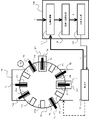
- FIG. 1 is a block diagram showing a relationship between a tool management device and a target device according to the first embodiment, which is a typical example of the present invention. Further, FIG. 2 is a schematic diagram showing an excerpt of a part of the specific structure of the target device shown in FIG.
- the tool management device 100 is connected to a target device (machine tool) 10 for holding a plurality of tools by wire or wirelessly, and a signal or a signal is transmitted between the machine tool 10 and the target device (machine tool) 10. It is configured as a processing system for exchanging data.
- a machine tool 10 including a swivel turret 16 as a tool holding mechanism is applied.
- the machine tool 10 includes a base portion 12, a work holding portion 14 that rotatably holds the work W around a predetermined rotation axis, a swivel type turret 16 that holds a plurality of tools T, and the swivel type. It is configured as a turret lathe including a turret holding unit 18 having a built-in drive mechanism for rotating the turret 16 and a control unit 19 for controlling the operation of the entire machine tool 10.
- a plurality of tools T are attached so that the machining blades are radially exposed to the swivel turret 16, and the swivel turret 16 rotates based on a command from the control unit 19. As a result, the specific tool T is brought into contact with the work W for machining.
- the swivel turret 16 has holding mechanisms such as chucks for radially attaching a plurality of tools T1 to T12 at holding positions P1 to P12, respectively.
- the holding positions P1 to P12 are arranged at equal intervals (that is, at an angle of 30 °) on the outer circumference of the swivel turret 16.
- the respective arrangement positions (angles) of the holding positions P1 to P12 are determined with the angle of the holding position P1 as the reference angle (0 °). Based on this reference angle, the command generation unit 130 of the tool management device 100, which will be described later, obtains the swivel amount (angle) when the swivel command of the swivel turret 16 is generated. Further, in the swivel turret 16, a delivery position EP for delivering (that is, attaching / detaching) the tool T is set.
- the tool management device 100 includes an information acquisition unit 110 for acquiring a configuration information CI including a current tool holding state in the tool holding mechanism (swivel type turret 16) of the machine tool 10, a configuration information CI, and a configuration information CI.
- the holding position setting unit 120 for setting the holding positions P1 to P12 for holding the tools T1 to T12 in the swivel turret 16 and the set holding positions P1 to P12 are delivered. It includes a command generation unit 130 that generates a drive command DC to be moved to the EP.
- the tool information TI includes information such as the total number and specifications of the managed tool T, the machining type executed by each tool T, etc., and is manually input by the operator or the information acquisition unit 110. Is acquired by accessing an external storage device (not shown) or the like.
- the configuration information CI includes information such as the structure of the swivel turret 16 of the machine tool 10 and whether or not the tools T1 to T12 are currently held at the holding positions P1 to P12, and is usually a machine tool. It is held by the control unit 19 of 10.
- the tool management device 100 does not need to permanently install a memory for storing and storing the current holding information of the tool T.
- the information acquisition unit 110 of the tool management device 100 acquires the configuration information CI of the machine tool 10 from the control unit 19 of the machine tool 10 and acquires the tool information TI for the tool T from the outside. Temporarily save the information of.
- the information acquisition unit 110 also has a function of extracting all or a part of the acquired configuration information CI and tool information TI and sending them to the holding position setting unit 120.
- the holding position setting unit 120 sets the holding positions P1 to P12 of the tool T newly attached to the swivel turret 16 based on the configuration information CI and the tool information TI sent from the information acquisition unit 110. Specifically, the holding position setting unit 120 describes the holding status of the tool T in the swivel turret 16 in the configuration information CI (that is, the availability of the holding positions P1 to P12) and the tool T to be attached in the tool information TI.
- the holding positions P1 to P12 for each tool T to be mounted are set in consideration of the number of turrets and specifications (size, etc.). Then, the information of the set holding positions P1 to P12 is sent to the command generation unit 130.
- the command generation unit 130 is a drive command for moving the set holding position P in the swivel turret 16 to the delivery position EP of the tool T based on the information of the holding position P sent from the holding position setting unit 120. Generate DC. Specifically, the current angle between the set holding position P and the delivery position EP is calculated, and the drive command DC for the turning operation of the turret corresponding to the angle is generated. Then, the generated drive command DC is transmitted to the control unit 19 of the machine tool 10.
- a method of calculating the angle directly formed or a specific holding of the swivel type turret 16 A method of calculating by the difference between the angle from the reference position to the set holding position P and the angle from the reference position to the delivery position EP may be adopted with the position P as the “reference position”. That is, for example, when the holding position P1 shown in FIG. 2 is set as the "reference position" in the swivel turret 16, when the holding position P11 is set, the angle from the holding position P11 to the holding position P1 which is the reference position is 60 °. Since the angle from the holding position P1 to the delivery position EP is 90 °, the instruction angle for the turning operation is 120 °.
- FIGS. 3 to 5 the specific operation of the tool management device according to the first embodiment will be described with reference to FIGS. 3 to 5.
- the case where the tool T is to be attached to the swivel turret 16 is illustrated, but the designated tool T is removed from the swivel turret 16 or replaced with another tool T. It may be applied in some cases.
- 3 to 5 are schematic views showing an example of the operation of the machine tool according to the command from the tool management device according to the first embodiment.
- the information acquisition unit 110 first acquires the configuration information CI for the swivel turret 16 from the control unit 19 of the machine tool 10.
- the configuration information CI includes, for example, the number and arrangement of holding positions P1 to P12 provided in the swivel turret 16, the number and arrangement of tools T1 to T12 already attached to the holding positions P1 to P12. Information such as a number and the current angle of the holding position P1 as a reference position is included. Regarding the positions where the tools T1 to T12 are attached, even if the sensors provided at the holding positions P1 to P12 detect the information on the presence or absence of the tool T and acquire the information via the control unit 19. good.
- the information acquisition unit 110 acquires the tool information TI related to the tool T to be replaced from the outside together with the configuration information CI. As described above, the tool information TI at this time includes the number of tools T to be replaced, specifications, and the like. Then, the information acquisition unit 110 sends the acquired configuration information CI and tool information TI to the holding position setting unit 120.
- the holding position setting unit 120 selects holding positions P1 to P12 of the swivel type turret 16 that match the tool T to be replaced based on the configuration information CI and the tool information TI, and the holding position number information is used as a command generation unit. Send to 130. Specifically, for example, in the case of the arrangement shown in FIG. 3, the holding position P2 closest to the holding position P1 which is the reference position and to which the tool T is not attached is selected.
- the command generation unit 130 how much movement amount should the swivel turret 16 move so that the holding position P2 with respect to the tool T set by the holding position setting unit 120 is located at the delivery position EP of the tool T (that is,). , How much angle should be turned), and a drive command DC for turning the swivel turret 16 by the calculated movement amount to the control unit 19 of the machine tool 10 is generated.
- the turning angle 60 ° shown in FIG. 4
- the clockwise drive command DC corresponding to the turning angle is generated.
- the holding position setting unit 120 and the command generation unit 130 repeat the above operations based on the already acquired configuration information CI.
- the information acquisition unit 110 acquires the configuration information CI including the current tool holding state in the tool holding mechanism (swivel type turret 16), so that the tool management device 100 itself always obtains the configuration information of the machine tool 10. There is no need to add memory to store the CI.
- the holding position that minimizes the amount of movement (that is, the turning angle) from the current position to the delivery position EP is adopted. It may be configured as follows. Specifically, since the movement amount of the holding position P5 (turning angle 30 °) is smaller than the movement amount of the holding position P2 (turning angle 60 °), the holding position P5 is selected and counterclockwise. The drive command DC may be output. As a result, the mounting time (replacement time) of the tool T can be shortened.
- FIG. 6 is a schematic view showing a first modification of the tool management device according to the first embodiment.
- the first modification shows a case where the large-diameter tools T1 to T3 and the small-diameter tools T4 to T10 are mixed and attached to the swivel turret 16 of the machine tool 10.
- the swivel type turret 16 applied to the tool management device 100 of the first modification is the tool T shown by the above-mentioned large-diameter tools T1 to T3 and small-diameter tools T4 to T10.
- Each type has a plurality of type areas A1 and A2.
- the holding position setting unit 120 of the tool management device 100 sets the holding position P for each tool T with reference to the respective calculation reference positions in the type areas A1 and A2.
- the holding positions P1 to P3 corresponding to the large-diameter tools are arranged at equal intervals in the type region A1 and the holding positions are used as the calculation standard of the movement amount (turning angle).
- the movement amount is calculated by setting P1 as the reference position.
- the holding positions P4 to P10 corresponding to the small-diameter tools are arranged at equal intervals in the type region A2, and the holding position P4 is used as the reference position for calculating the movement amount (turning angle). Set to to calculate the amount of movement.
- FIG. 7 is a schematic view showing a second modification of the tool management device according to the first embodiment.
- the second modification when the mounting state of the tool T of the swivel turret 16 is changed, the function of changing the configuration information CI stored in the control unit 19 of the machine tool 10 is provided.
- the tool management device 100 of the second modification is generated by the command generation unit 130 in addition to the information acquisition unit 110, the holding position setting unit 120, and the command generation unit 130 shown in FIG. It further includes a configuration information update unit 140 that updates the configuration information CI based on the drive command DC.
- the configuration information update unit 140 changes the configuration information CI acquired by the information acquisition unit 110 in consideration of the drive command DC to the control unit 19 of the machine tool 10 generated by the command generation unit 130, and the changed configuration information CI. Has a function of returning to the control unit 19.
- the configuration information CI first acquired by the information acquisition unit 110 includes information that "the tool T is not attached to the holding position P2". It has been. Then, as shown in FIG. 4, when the tool T2 is newly attached to the holding position P2, it is old if there is no information that the tool T2 is attached to the holding position P2 when another tool T is attached next time. There is a possibility that the holding position P2 holding position setting unit 120 to which the tool T2 is already attached repeatedly selects and sets the configuration information CI.
- the configuration information update unit 140 included in the tool management device 100 has acquired the change information for the holding position P included in the drive command DC output from the command generation unit 130 by the information acquisition unit 110.
- a new configuration information CI'that has been overwritten and updated for the configuration information CI is created and transmitted to the control unit 19 of the machine tool 10. This enables tool management in consideration of the latest information on the holding status of the tool T of the swivel type turret 16. At this time, when the tool T is continuously attached or replaced, it is preferable that the information acquisition unit 110 operates so as to always acquire the latest configuration information CI.
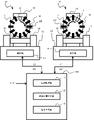
- FIG. 8 is a schematic view showing a third modification of the tool management device according to the first embodiment.
- the tool management device 100 is connected to the machine tools 10 and 10'which are a plurality of target devices, and tool management is performed for the plurality of target devices.
- the tool management device 100 of the third modification is connected to the machine tool 10 and the machine tool 10'which are the target devices for holding a plurality of tools by wire or wirelessly, and these plurality of machines are machined. It is configured as a processing system for exchanging signals and data with machines 10 and 10'.
- FIG. 9 illustrates a case where the tool management device 100 is connected to two machine tools 10 and 10', but the tool management device 100 is connected to three or more target devices. It may be configured.
- the information acquisition unit 110 of the tool management device 100 responds to the tool information TI by individually connecting to a plurality of machine tools 10 and 10'when attaching or exchanging a predetermined tool T.
- the tool T can be distributed to the machine tool 10 or 10'and managed. That is, it is possible to attach or replace the tool to the machine tool specified for each type of machining on the work, machining conditions, or specifications of the tool.
- the information acquisition unit 110 of the tool management device 100 first acquires the tool information TI of the tool T.
- the configuration information CI and CI' are acquired from the control units 19 and 19'of the machine tools 10 and 10', respectively.
- the information acquisition unit 110 selects the configuration information CI as appropriate configuration information that matches the acquired tool information TI.
- the holding position setting unit 120 sets the holding position P of the tool T in the swivel type turret 16 based on the selected configuration information CI and tool information TI. Then, the command generation unit 130 generates a drive command DC to transfer the set holding position P to the delivery position EP and outputs the drive command DC to the control unit 19.
- the information acquisition unit 110 of the tool management device 100 acquires the tool information TI'of the tool T'. Then, the information acquisition unit 110 selects the configuration information CI'as appropriate configuration information that matches the newly acquired tool information TI'.
- the holding position setting unit 120 sets the holding position P'of the tool T in the swivel turret 16'based on the selected configuration information CI'and the tool information TI'. Then, the command generation unit 130 generates a drive command DC'to move to the set holding position P'and moves it to the transfer position EP'and outputs it to the control unit 19'.
- the tool T to be attached or replaced can be provided with appropriate swivel turrets 16 and 16'in consideration of the configuration information CI and CI'of the plurality of machine tools 10 and 10'. It can be selected, installed and managed.
- the configuration information CIs and CIs of the plurality of machine tools 10 and 10'are acquired is exemplified first, but the configuration information CIs are obtained according to the acquired tool information TIs and TIs. Alternatively, it may be configured to selectively acquire CI'.
- the information acquisition unit acquires the configuration information including the current tool holding state in the tool holding mechanism (swivel type turret), so that the tool management
- the device itself does not always require a memory for storing the configuration information of the target device (machine tool).
- the holding position setting unit sets the holding position for holding the tool in the tool holding mechanism based on the above configuration information and the tool information of the tool, and the command generation unit hands over the holding position of the tool holding mechanism to the tool.
- the holding position is set based on the configuration information acquired by the information acquisition unit and the drive command is generated. Therefore, even if the specifications of the target device are changed or the target device itself is changed, it is possible to cope with the change and it is possible to eliminate the need for addition or change of the memory.
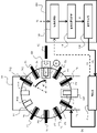
- FIG. 9 is a block diagram showing the relationship between the tool management device and the target device according to the second embodiment of the present invention.
- those having the same or common configurations as those of the first embodiment shown in FIGS. 1 to 8 are designated by the same reference numerals, and the description thereof will be repeated. Omit.
- the tool management device 100 is connected to a target device (tool storage device) 20 for holding a plurality of tools by wire or wirelessly, and is connected to the tool storage device 20. It is configured as a tool storage system for exchanging signals and data.
- the tool storage device 20 including the chain type tool stocker 24 as the tool holding mechanism is applied.
- the tool storage device 20 includes a base portion 22, a chain-type tool stocker 24 that holds and stores a plurality of tools T, and a pair of pulleys 26 that rotate the chain-type tool stocker 24. It constitutes a tool storage unit including a tool stocker holding unit 28 having a built-in drive mechanism for rotating the pulley 26 of the tool, and a control unit 29 for controlling the operation of the entire tool storage device 20.
- a plurality of tools T1 to T14 are held at holding positions (see reference numeral P1 in FIG. 9) of individual chain elements C1 to C14 constituting the chain type tool stocker 24, and the control unit is used.
- the pair of pulleys 26 rotate based on the command from 29, and the chain type tool stocker 24 rotates to move the specific tool T to the delivery position EP.
- a tool holder (not shown) in which a plurality of chain elements C1 to C14 are rotatably connected by a predetermined connecting mechanism (not shown) and holds a plurality of tools T1 to T14. (Not shown) are provided at the holding positions P1 to P14, respectively.
- the holding positions P1 to P14 are arranged so as to be evenly spaced with respect to the connecting direction of the chain type tool stocker 24.
- the holding positions P1 to P14 are determined by the distance from the reference position with the position of the holding position P1 as the reference position. That is, based on the distance (length) from this reference position, the turning amount (chain elements C1 to) when the turning command of the chain type tool stocker 24 is generated in the command generation unit 130 of the tool management device 100 described later. The moving distance of C14) is obtained.
- the information acquisition unit 110 first acquires the configuration information CI about the chain type tool stocker 24 from the control unit 29 of the tool storage device 20.
- the configuration information CI as an example, the number and arrangement of holding positions P1 to P14 provided in the chain type tool stocker 24, the number and arrangement of tools T1 to T14 already attached to the holding positions P1 to P14, and the like.
- Information such as a number and the current position of the holding position P1 as a reference position is included.
- the sensors provided at the holding positions P1 to P14 detect the information on the presence / absence of the tool T and control the positions where the tools T1 to T14 are attached. It may be acquired via the unit 29.
- the information acquisition unit 110 acquires the tool information TI related to the tool T to be replaced from the outside together with the configuration information CI. As described above, the tool information TI at this time includes the number of tools T to be replaced, specifications, and the like. Then, the information acquisition unit 110 sends the acquired configuration information CI and tool information TI to the holding position setting unit 120.
- the holding position setting unit 120 selects holding positions P1 to P14 of the chain type tool stocker 24 suitable for the tool T to be replaced based on the configuration information CI and the tool information TI, and generates a command for the number information of the holding position. Send to unit 130. At this time, as in the case of the first embodiment, as an example thereof, the holding position closest to the holding position P1 which is the reference position and to which the tool T is not attached is selected.
- the amount of movement of the chain element C having the holding position P set so that the holding position P with respect to the tool T set by the holding position setting unit 120 is located at the delivery position EP of the tool T. (That is, how much the chain-type tool stocker 24 should turn) is calculated, and the drive for turning the chain-type tool stocker 24 with respect to the control unit 29 of the tool storage device 20.
- Generate command DC Specifically, the movement amount of the set holding position P to the delivery position EP is calculated, a drive command DC corresponding to the rotation amount of the pair of pulleys 26 corresponding to the movement amount is generated, and the control unit 29 is generated. Output.
- the holding position setting unit 120 and the command generation unit 130 repeat the above operations based on the already acquired configuration information CI.
- the information acquisition unit 110 acquires the configuration information CI including the current tool holding state in the tool holding mechanism (chain type tool stocker 24), so that the tool management device 100 itself is always the tool storage device 20. It is not necessary to add a memory for storing the configuration information CI.
- the tool management device according to the second embodiment is changed. Since the information acquisition unit acquires and manages configuration information including the current tool holding state in the tool holding mechanism (chain type tool stocker), the tool management device itself always stores the configuration information of the target device (machine tool). No need for memory. Further, the holding position setting unit sets the holding position for holding the tool in the tool holding mechanism based on the above configuration information and the tool information of the tool, and the command generation unit hands over the holding position of the tool holding mechanism to the tool.
- the holding position is set based on the configuration information acquired by the information acquisition unit and the drive command is generated. Therefore, even if the specifications of the target device are changed or the target device itself is changed, it is possible to cope with the change and it is possible to eliminate the need for addition or change of the memory.
- the case of a chain type tool stocker is illustrated as the tool holding mechanism in FIG. 9, but a well-known structure such as a rack type magazine or a drum type magazine is applied as the tool holding mechanism. May be. Also in these structures, the effect of the present invention can be obtained by calculating the amount of movement between the holding position for holding the tool and the delivery position and outputting the drive command.
- FIG. 10 is a block diagram showing the relationship between the tool management device and the target device according to the third embodiment of the present invention.
- the same reference numerals are given to those that can adopt the same or common configurations as those of the first embodiment and the second embodiment shown in FIGS. 1 to 9. The description of these repetitions will be omitted.
- the tool management device 100 has, as an example, a machine tool 10 that holds a plurality of tools T shown in FIG. 1 and processes a work W, and FIG.
- the tool storage device 20 for storing the plurality of tools T shown and the tool delivery device 30 for delivering tools between the machine tool 10 and the tool storage device 20 are connected to each other by wire or wirelessly.
- the tool management device 100 according to the third embodiment constitutes a processing system for exchanging signals and data with each other between the machine tool 10, the tool storage device 20, and the tool delivery device 30.
- the machine tool 10 is configured as a turret lathe including a base portion 12, a work holding portion 14, a swivel turret 16, a turret holding portion 18, and a control unit 19.
- the tool storage device 20 constitutes a tool storage unit including a base portion 22, a chain type tool stocker 24, a pair of pulleys 26, a tool stocker holding portion 28, and a control unit 29.
- the delivery position EP1 of the machine tool 10 and the delivery position EP2 of the tool storage device 20 are arranged at opposite positions.
- the tool delivery device 30 includes a base portion 32, a robot arm 34 formed of a plurality of arms, a tool grip portion 36 provided at one end of the robot arm 34, and the entire tool delivery device 30. It is configured as an articulated robot mechanism including a control unit 38 that controls the operation of the robot.
- the tool delivery device 30 is arranged so that the tool T can be exchanged between the machine tool 10 and the tool storage device 20 by rotating the robot arm 34 with respect to the base portion 32.
- the information acquisition unit 110 of the tool management device 100 first uses the tool T.
- the tool information TI is acquired, and the configuration information CI2 is acquired from the control unit 29 of the tool storage device 20.
- the holding position setting unit 120 determines whether or not there is a tool T corresponding to the acquired tool information TI in the chain type tool stocker 24 of the tool storage device 20, and if the corresponding tool T exists, it is attached.
- the holding position P is set and sent to the command generation unit 130.
- the command generation unit 130 generates a drive command DC2 for moving the holding position P set in the chain type tool stocker 24 to the delivery position EP2, and outputs the drive command DC2 to the control unit 29.
- the pair of pulleys 26 of the tool storage device 20 rotate, the chain type tool stocker 24 rotates, and the designated tool T is moved to the delivery position EP2.
- the information acquisition unit 110 acquires the configuration information CI1 from the control unit 19 of the machine tool 10. Then, the holding position setting unit 120 determines whether or not there is a holding position P corresponding to the tool T designated in the swivel turret 16 of the machine tool 10, sets the holding position P, and causes the command generation unit 130 to set the holding position P. send.
- the command generation unit 130 generates a drive command DC1 for moving the holding position P set in the swivel turret 16 to the delivery position EP1 and outputs the drive command DC1 to the control unit 19.
- the swivel turret 16 of the machine tool 10 rotates, and the holding position P for attaching the designated tool T is moved to the delivery position EP1.
- the command generation unit 130 generates a drive command DC3 for the control unit 38 of the tool delivery device 30 to transfer the tool T from the delivery position EP2 of the tool storage device 20 to the delivery position EP1 of the machine tool 10. And output.
- the drive command DC3 may be simply a command to start the delivery operation to the tool delivery device 30, or may be an operation command including the position from the delivery position EP2 to the delivery position EP1 and the movement of the robot arm 34.
- the drive command DC3 to the tool delivery device 30 is output to the drive command DC1 or DC2 to the machine tool 10 or the tool storage device 20 and then generated and output has been exemplified.
- the command DC3 may be configured to be generated and output during operation by the drive command DC1 or DC2. As a result, the waiting time for the tool delivery device 30 to operate is reduced, so that the time required for moving the tool T can be reduced.
- the tool management device is the tool management device itself even if it is a machining system having an automatic tool change function including both the machine tool 10 and the tool storage device 20.
- a memory for storing the configuration information of the target device (machine tool) at all times.
- the present invention can also be applied in combination with the above-described embodiments.
- tool management can be performed on a plurality of tool storage devices.
- the tool management device connected to the machining system shown in the third embodiment may be provided with the configuration provided with the configuration information updating unit shown in the second modification of the first embodiment.
- the present invention is not limited to the above embodiment, and can be appropriately modified without departing from the spirit.
- Machine tool 10 Swivel type turret 20 Tool storage device 24 Chain type tool stocker 30 Tool delivery device 34 Robot arm 100 Tool management device 110 Information acquisition unit 120 Holding position setting unit 130 Command generation unit 140 Configuration information update unit
Landscapes
- Engineering & Computer Science (AREA)
- Mechanical Engineering (AREA)
- Physics & Mathematics (AREA)
- General Physics & Mathematics (AREA)
- Automation & Control Theory (AREA)
- Automatic Tool Replacement In Machine Tools (AREA)
Abstract
Description
図1は、本発明の代表的な一例である、第1の実施形態による工具管理装置と対象装置との関連を示すブロック図である。また、図2は、図1で示した対象装置の具体的な構造の一部を抜粋して示した概略図である。
図9は、本発明の第2の実施形態による工具管理装置と対象装置との関連を示すブロック図である。なお、第2の実施形態においては、図1~図8に示した第1の実施形態と同一あるいは共通の構成を採用し得るものについては、同一の符号を付してこれらの繰り返しの説明は省略する。
図10は、本発明の第3の実施形態による工具管理装置と対象装置との関連を示すブロック図である。なお、第3の実施形態においては、図1~図9に示した第1の実施形態及び第2の実施形態と同一あるいは共通の構成を採用し得るものについては、同一の符号を付してこれらの繰り返しの説明は省略する。
16 旋回型タレット
20 工具保管装置
24 チェーン式工具ストッカ
30 工具受け渡し装置
34 ロボットアーム
100 工具管理装置
110 情報取得部
120 保持位置設定部
130 指令生成部
140 構成情報更新部
Claims (8)
- 複数の工具を保持する工具保持機構を備えた対象装置に対して前記工具を管理する工具管理装置であって、
前記工具保持機構における現在の工具保持状態を含む構成情報を取得する情報取得部と、
前記構成情報及び前記工具の工具情報に基づいて、前記工具保持機構における前記工具を保持する保持位置を設定する保持位置設定部と、
前記工具保持機構の前記保持位置を、前記工具を受け渡す受け渡し位置に移動させる駆動指令を生成する指令生成部と、
を含む工具管理装置。 - 前記保持位置設定部は、前記受け渡し位置への移動量が最小となるように前記保持位置を設定する
請求項1に記載の工具管理装置。 - 前記工具保持機構は、前記工具の種類ごとに複数の種別領域を有しており、
前記保持位置設定部は、前記種別領域における算出基準位置を基準として、前記工具ごとに前記保持位置を設定する
請求項1に記載の工具管理装置。 - 前記駆動指令に基づいて、前記構成情報を更新する構成情報更新部をさらに含む
請求項1~3のいずれか1項に記載の工具管理装置。 - 前記対象装置は複数で構成されており、
前記情報取得部は、当該複数の前記対象装置から各々の前記対象装置に対応する構成情報を取得するとともに、前記工具情報を考慮して前記対応する構成情報のうちの適切なものを選択する機能をさらに有する
請求項1~4のいずれか1項に記載の工具管理装置。 - 前記対象装置は工作機械であり、前記工具保持機構は前記工作機械の旋回型タレットである
請求項1~5のいずれか1項に記載の工具管理装置。 - 前記対象装置は工具保管装置であり、前記工具保持機構は前記工具保管装置の工具ストッカである
請求項1~5のいずれか1項に記載の工具管理装置。 - 前記対象装置は、工作機械及び工具保管装置であり、
前記工作機械は、第1の工具保持機構として旋回型タレットを備え、
前記工具保管装置は、第2の工具保持機構として工具ストッカを備え、
前記保持位置設定部は、前記第1の工具保持機構に対する第1の構成情報及び前記工具情報に基づいて第1の保持位置を設定するとともに、前記第2の工具保持機構に対する第2の構成情報及び前記工具情報に基づいて第2の保持位置を設定し、
前記指令生成部は、前記第1の保持位置を前記受け渡し位置に移動させる第1の駆動指令を生成するとともに、前記第2の保持位置を前記受け渡し位置に移動させる第2の駆動指令を生成する
請求項1~5のいずれか1項に記載の工具管理装置。
Priority Applications (4)
| Application Number | Priority Date | Filing Date | Title |
|---|---|---|---|
| CN202180074031.XA CN116547106A (zh) | 2020-11-06 | 2021-11-04 | 对具备保持多个工具的工具保持机构的对象装置的工具进行管理的工具管理装置 |
| JP2022560797A JP7810654B2 (ja) | 2020-11-06 | 2021-11-04 | 複数の工具を保持する工具保持機構を備えた対象装置の工具を管理する工具管理装置 |
| US18/249,970 US20230398650A1 (en) | 2020-11-06 | 2021-11-04 | Tool management device that manages tools of target device including tool holding mechanism that holds a plurality of tools |
| DE112021004516.4T DE112021004516T5 (de) | 2020-11-06 | 2021-11-04 | Werkzeugverwaltungsvorrichtung zur Verwaltung von Werkzeugen einer Zielvorrichtung mit einem Werkzeughaltemechanismus, der mehrere Werkzeuge hält |
Applications Claiming Priority (2)
| Application Number | Priority Date | Filing Date | Title |
|---|---|---|---|
| JP2020185677 | 2020-11-06 | ||
| JP2020-185677 | 2020-11-06 |
Publications (2)
| Publication Number | Publication Date |
|---|---|
| WO2022097660A1 true WO2022097660A1 (ja) | 2022-05-12 |
| WO2022097660A9 WO2022097660A9 (ja) | 2023-04-06 |
Family
ID=81457041
Family Applications (1)
| Application Number | Title | Priority Date | Filing Date |
|---|---|---|---|
| PCT/JP2021/040495 Ceased WO2022097660A1 (ja) | 2020-11-06 | 2021-11-04 | 複数の工具を保持する工具保持機構を備えた対象装置の工具を管理する工具管理装置 |
Country Status (5)
| Country | Link |
|---|---|
| US (1) | US20230398650A1 (ja) |
| JP (1) | JP7810654B2 (ja) |
| CN (1) | CN116547106A (ja) |
| DE (1) | DE112021004516T5 (ja) |
| WO (1) | WO2022097660A1 (ja) |
Cited By (2)
| Publication number | Priority date | Publication date | Assignee | Title |
|---|---|---|---|---|
| KR102642083B1 (ko) * | 2023-12-15 | 2024-02-29 | 주식회사 이안하이텍 | 6축다관절로봇과 연동된 atc시스템 |
| JP7530472B1 (ja) | 2023-03-27 | 2024-08-07 | Dmg森精機株式会社 | マガジン装置、及び、それを備えた工作機械 |
Citations (4)
| Publication number | Priority date | Publication date | Assignee | Title |
|---|---|---|---|---|
| JPS6248439A (ja) * | 1985-08-29 | 1987-03-03 | Toshiba Corp | 工具マガジン装置 |
| JP2008238356A (ja) * | 2007-03-28 | 2008-10-09 | Brother Ind Ltd | 工作機械、工作機械の工具マガジン制御プログラム及び工具マガジン制御プログラム記録媒体 |
| JP2020015143A (ja) * | 2018-07-26 | 2020-01-30 | ファナック株式会社 | 工具管理システム、工具管理装置及び工具管理方法 |
| JP6779406B1 (ja) * | 2020-07-20 | 2020-11-04 | Dmg森精機株式会社 | 工作機械 |
Family Cites Families (6)
| Publication number | Priority date | Publication date | Assignee | Title |
|---|---|---|---|---|
| US4581810A (en) * | 1981-01-09 | 1986-04-15 | Toshiba Kikai Kabushiki Kaisha | Method and apparatus for controlling tool magazines |
| JPH02172649A (ja) | 1988-12-24 | 1990-07-04 | Toshiba Corp | 工具入替え装置 |
| JP3207125B2 (ja) | 1996-08-22 | 2001-09-10 | スター精密株式会社 | タレット工具選択指令方法 |
| JP2004066417A (ja) * | 2002-08-08 | 2004-03-04 | Mori Seiki Co Ltd | 工具管理方法及び工具管理装置 |
| JP5253897B2 (ja) * | 2008-06-17 | 2013-07-31 | 株式会社森精機製作所 | 工具マガジン装置における工具配置替え方法およびその装置 |
| DE102013012633A1 (de) | 2013-07-29 | 2015-01-29 | Alfing Kessler Sondermaschinen Gmbh | Werkzeugmaschine mit einer Werkstückwechseleinrichtung |
-
2021
- 2021-11-04 US US18/249,970 patent/US20230398650A1/en active Pending
- 2021-11-04 JP JP2022560797A patent/JP7810654B2/ja active Active
- 2021-11-04 CN CN202180074031.XA patent/CN116547106A/zh active Pending
- 2021-11-04 DE DE112021004516.4T patent/DE112021004516T5/de active Pending
- 2021-11-04 WO PCT/JP2021/040495 patent/WO2022097660A1/ja not_active Ceased
Patent Citations (4)
| Publication number | Priority date | Publication date | Assignee | Title |
|---|---|---|---|---|
| JPS6248439A (ja) * | 1985-08-29 | 1987-03-03 | Toshiba Corp | 工具マガジン装置 |
| JP2008238356A (ja) * | 2007-03-28 | 2008-10-09 | Brother Ind Ltd | 工作機械、工作機械の工具マガジン制御プログラム及び工具マガジン制御プログラム記録媒体 |
| JP2020015143A (ja) * | 2018-07-26 | 2020-01-30 | ファナック株式会社 | 工具管理システム、工具管理装置及び工具管理方法 |
| JP6779406B1 (ja) * | 2020-07-20 | 2020-11-04 | Dmg森精機株式会社 | 工作機械 |
Cited By (4)
| Publication number | Priority date | Publication date | Assignee | Title |
|---|---|---|---|---|
| JP7530472B1 (ja) | 2023-03-27 | 2024-08-07 | Dmg森精機株式会社 | マガジン装置、及び、それを備えた工作機械 |
| WO2024204210A1 (ja) * | 2023-03-27 | 2024-10-03 | Dmg森精機株式会社 | マガジン装置、及び、それを備えた工作機械 |
| JP2024138898A (ja) * | 2023-03-27 | 2024-10-09 | Dmg森精機株式会社 | マガジン装置、及び、それを備えた工作機械 |
| KR102642083B1 (ko) * | 2023-12-15 | 2024-02-29 | 주식회사 이안하이텍 | 6축다관절로봇과 연동된 atc시스템 |
Also Published As
| Publication number | Publication date |
|---|---|
| JP7810654B2 (ja) | 2026-02-03 |
| US20230398650A1 (en) | 2023-12-14 |
| WO2022097660A9 (ja) | 2023-04-06 |
| CN116547106A (zh) | 2023-08-04 |
| DE112021004516T5 (de) | 2023-07-06 |
| JPWO2022097660A1 (ja) | 2022-05-12 |
Similar Documents
| Publication | Publication Date | Title |
|---|---|---|
| WO2022097660A1 (ja) | 複数の工具を保持する工具保持機構を備えた対象装置の工具を管理する工具管理装置 | |
| JP2016002644A (ja) | 工具格納位置の変更を可能としたマガジン旋回式工具交換手段 | |
| JPH0220371B2 (ja) | ||
| JP2007290113A (ja) | 数値制御装置付き工作機械の自動工具交換方法及び自動工具交換装置 | |
| KR20180008177A (ko) | 자동 공구교환 장치 및 이를 이용한 자동 공구교환 방법 | |
| US20200293005A1 (en) | Machine tool, processing system and management system | |
| JP4694715B2 (ja) | 電気部品装着ライン | |
| JPS59184911A (ja) | 工作物輪郭に工具を倣わせる方法 | |
| JP6342940B2 (ja) | 工作機械用自動工具交換システム | |
| JP4947534B2 (ja) | 工作機械及び工作機械を操作する方法 | |
| JP6391861B1 (ja) | 選択装置、選択方法及びプログラム | |
| US20230278152A1 (en) | Machine tool | |
| JP2022016711A (ja) | 工作機械 | |
| JP7137722B1 (ja) | 工作機械 | |
| JP2010523345A (ja) | 工具マガジンおよび中間格納ステーションを含む工作機械の制御 | |
| JP7414466B2 (ja) | 最適化処理装置 | |
| JP5186055B2 (ja) | 電気回路板組立システム | |
| TW202113520A (zh) | 工具資訊設定裝置及工作機械 | |
| JP7203254B1 (ja) | 工作機械 | |
| JP2007537521A (ja) | データ媒体に記憶された機械の制御装置のための制御ファイルを含んでいるデータ媒体、およびこれと関連する方法と装置 | |
| JPS641270B2 (ja) | ||
| KR20160124503A (ko) | 공구 교환 시간을 획기적으로 감소시킬 수 있는 자동 공구 교환 장치를 포함하는 공작 기계 | |
| JP5396529B2 (ja) | 電気回路板組立システム | |
| JP2829212B2 (ja) | 自動工具交換制御方法及び装置 | |
| WO2018096676A1 (ja) | 数値制御装置及び工具管理生成プログラム |
Legal Events
| Date | Code | Title | Description |
|---|---|---|---|
| 121 | Ep: the epo has been informed by wipo that ep was designated in this application |
Ref document number: 21889213 Country of ref document: EP Kind code of ref document: A1 |
|
| ENP | Entry into the national phase |
Ref document number: 2022560797 Country of ref document: JP Kind code of ref document: A |
|
| WWE | Wipo information: entry into national phase |
Ref document number: 202180074031.X Country of ref document: CN |
|
| 122 | Ep: pct application non-entry in european phase |
Ref document number: 21889213 Country of ref document: EP Kind code of ref document: A1 |