WO2022097632A1 - 吸着ノズル装置 - Google Patents
吸着ノズル装置 Download PDFInfo
- Publication number
- WO2022097632A1 WO2022097632A1 PCT/JP2021/040369 JP2021040369W WO2022097632A1 WO 2022097632 A1 WO2022097632 A1 WO 2022097632A1 JP 2021040369 W JP2021040369 W JP 2021040369W WO 2022097632 A1 WO2022097632 A1 WO 2022097632A1
- Authority
- WO
- WIPO (PCT)
- Prior art keywords
- diameter
- nozzle
- small
- diameter pipe
- pipe
- Prior art date
- Legal status (The legal status is an assumption and is not a legal conclusion. Google has not performed a legal analysis and makes no representation as to the accuracy of the status listed.)
- Ceased
Links
Images





Classifications
-
- B—PERFORMING OPERATIONS; TRANSPORTING
- B25—HAND TOOLS; PORTABLE POWER-DRIVEN TOOLS; MANIPULATORS
- B25J—MANIPULATORS; CHAMBERS PROVIDED WITH MANIPULATION DEVICES
- B25J15/00—Gripping heads and other end effectors
- B25J15/06—Gripping heads and other end effectors with vacuum or magnetic holding means
-
- B—PERFORMING OPERATIONS; TRANSPORTING
- B25—HAND TOOLS; PORTABLE POWER-DRIVEN TOOLS; MANIPULATORS
- B25J—MANIPULATORS; CHAMBERS PROVIDED WITH MANIPULATION DEVICES
- B25J15/00—Gripping heads and other end effectors
- B25J15/06—Gripping heads and other end effectors with vacuum or magnetic holding means
- B25J15/0616—Gripping heads and other end effectors with vacuum or magnetic holding means with vacuum
Definitions
- One aspect of the present invention relates to a suction nozzle device for vacuum suctioning a work.
- Patent Document 1 A structure has also been proposed in which any of a plurality of nozzles having different diameters is projected (see Patent Document 1), but in this structure, the flow path is fixed to the inner diameter cross-sectional area of the nozzle having the smallest diameter, so that the work can be constructed. It was difficult to optimize the flow rate according to the weight.
- Nozzle devices with different diameters can be selected according to the work, can be inserted into narrow spaces, can be realized with weight reduction, and the flow rate can be changed according to the nozzle selection. It is rare.
- the suction nozzle device for vacuum sucking the work includes a large-diameter pipe, a large-diameter nozzle attached to the tip of the large-diameter pipe, and a large-diameter pipe coaxially inserted into the large-diameter pipe.
- a small diameter pipe whose outer diameter is shorter than the inner diameter of the large diameter pipe to provide a gap between the two, a small diameter nozzle attached to the tip of the small diameter pipe, and a relatively movable support between the large diameter pipe and the small diameter pipe. It is equipped with a support mechanism.
- the small-diameter nozzle changes depending on whether the small-diameter nozzle protrudes or is pulled in with respect to the large-diameter nozzle, and the small-diameter nozzle with respect to the inner edge of the rear end of the large-diameter nozzle.
- the closeness of the outer peripheral surfaces closes the gap between the large-diameter pipe and the small-diameter pipe, and the flow path cross-sectional area of the flow path through which the gas flows is set to the inner-diameter cross-sectional area of the small-diameter pipe, and the large-diameter nozzle.
- the outer peripheral surface of the small diameter nozzle is close to the inner edge of the rear end of the large diameter nozzle, and the flow path cross-sectional area is set to a value within the area range that is less than the inner diameter cross-sectional area of the large-diameter nozzle and exceeds the inner diameter cross-sectional area of the small-diameter nozzle. It changes depending on the state of being done.
- nozzles having different diameters can be selected according to the work, can be inserted into a narrow place, and can be realized together with weight reduction. Further, the cross-sectional area of the flow path through which the gas flows can be continuously changed with the relative movement between the large-diameter pipe and the small-diameter pipe.
- FIG. 1 is a perspective view of the entire end effector equipped with the suction nozzle device according to the embodiment.
- FIG. 2 is a vertical cross-sectional view of the suction nozzle device of FIG.
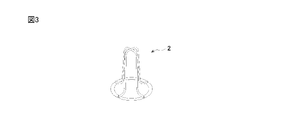
- FIG. 3 is a perspective view of the work entry protection bracket of FIG.
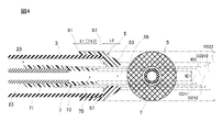
- FIG. 4 is an enlarged view of the nozzle tip portion of FIG.
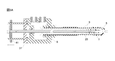
- FIG. 5A is a vertical sectional view showing a first state of the suction nozzle device of FIG.
- FIG. 5B is a vertical sectional view showing a second state of the suction nozzle device of FIG.
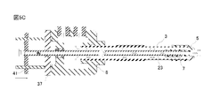
- FIG. 5C is a vertical sectional view showing a third state of the suction nozzle device of FIG.
- FIG. 5A is a vertical sectional view showing a first state of the suction nozzle device of FIG.
- FIG. 5B is a vertical sectional view showing a second state of the suction nozzle device of FIG.
- FIG. 5C is a vertical sectional view showing a third state of the suction nozzle device
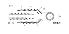
- FIG. 6A is a vertical cross-sectional view showing the cross-sectional area of the flow path corresponding to the first state of FIG. 5A.
- FIG. 6B is a vertical cross-sectional view showing the cross-sectional area of the flow path corresponding to the second state of FIG. 5B.
- FIG. 6C is a vertical cross-sectional view showing the cross-sectional area of the flow path corresponding to the third state of FIG. 5C.
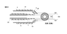
- FIG. 6D is a vertical cross-sectional view showing the cross-sectional area of the flow path corresponding to the third state in the modified example of the suction nozzle device of FIG.
- the suction nozzle device 1 As shown in FIG. 1, the suction nozzle device 1 according to the present embodiment is incorporated in an end effector for vacuum suction (simply also referred to as a hand) attached to the tip of a robot arm.
- the suction nozzle device 1 has a long circular tube (hereinafter referred to as a large diameter pipe) 3.
- a nozzle (referred to as a large diameter nozzle) 5 is attached to the tip of the large diameter pipe 3.
- a long circular pipe (small diameter pipe) having a smaller diameter than the large diameter pipe 3 described later is coaxially inserted into the large diameter pipe 3.
- a small diameter nozzle 7 is attached to the tip of this small diameter pipe.
- the large-diameter nozzle 5 and the small-diameter nozzle 7 are each made of a resin material such as urethane or synthetic rubber, which is air-impermeable and has elasticity.
- the outer diameter of the small diameter pipe is shorter than the inner diameter of the large diameter pipe 3, and a gap is provided between the large diameter pipe 3 and the small diameter pipe.
- the small-diameter pipe is provided so as to be movable along the central axis with respect to the large-diameter pipe 3, and the small-diameter nozzle 7 is pulled into the inside of the large-diameter pipe 3 with the movement, and the large-diameter pipe 3 is provided.
- the state in which the nozzle 5 protrudes with respect to the small-diameter nozzle 7 and the state in which the small-diameter nozzle 7 protrudes with respect to the large-diameter nozzle 5 change.
- the small-diameter nozzle 7 is separated from the large-diameter nozzle 5, and the gap space between the large-diameter pipe 3 and the small-diameter pipe is opened.
- the flow path cross-sectional area which is the main variable that determines the flow rate through which the gas (air) flows, is secured in the inner diameter cross-sectional area of the large-diameter nozzle 5.
- the inner-diameter cross-sectional area of the large-diameter nozzle 5 and the inner-diameter cross-sectional area of the small-diameter nozzle 7 are the flow path cross-sectional areas according to the distance of the small-diameter nozzle 7 to the large-diameter nozzle 5. It changes continuously with.
- the large-diameter nozzle 5 and the small-diameter nozzle 7 can be selected according to the relative movement of the small-diameter pipe with respect to the large-diameter pipe 3, and the cross-sectional area of the flow path of the large-diameter nozzle 5 can be selected. It can be continuously changed between the inner diameter cross-sectional area and the inner diameter cross-sectional area of the small diameter nozzle 7. This will be described in detail below.
- a connection block 8 is connected to the rear end of the large diameter pipe 3.
- the connection block 8 has a hollow structure, and an airtight chamber (sealed chamber) is formed inside.
- a vacuum ejector 9 is connected to the connection block 8 via a vacuum hose 11.
- the joint of the vacuum ejector 9 is connected to the joint 17 opened in the hand base 15 via the vacuum hose 12.
- the joint 17 is connected to an external vacuum pump via a vacuum hose.
- the compressed air supplied from the external vacuum pump generates a vacuum pressure inside the vacuum ejector 9, and is exhausted from the exhaust duct via the silencer 13.
- the vacuum pressure generated inside the vacuum ejector 9 sucks in the air inside the airtight chamber inside the connection block 8 and the inside of the large diameter pipe 3.
- the airtight chamber inside the connection block 8 and the inside of the large diameter pipe 3 are formed in a vacuum state lower than the atmospheric pressure, and the work is attracted to the large diameter nozzle 5 or the small diameter nozzle 7.
- the electric actuator 19 is attached to the suction nozzle device 1 in order to move the small diameter pipe with respect to the large diameter pipe 3.
- a sensor box 21 for detecting the vertices of the loosely stacked workpieces as they are is attached to the hand base 15.
- connection block 8 is connected to the rear end of the large diameter pipe 3 and is sealed with an O-ring 25.
- the small diameter pipe 23 is inserted into the large diameter pipe 3, and the small diameter pipe 23 is positioned by the ball plunger 27 so as to be coaxial with the large diameter pipe 3.
- the outer diameter of the small diameter pipe 23 is shorter than the inner diameter of the large diameter pipe 3, and a gap space 29 is formed between the large diameter pipe 3 and the small diameter pipe.
- the gap space 29 communicates with the airtight chamber 31 inside the connection block 8 via the rear end opening of the large diameter pipe 3.
- a communication hole 33 is opened in the middle of the small diameter pipe 23, and the internal space of the small diameter pipe 23 communicates with the gap space 29 between the large diameter pipe 3 and the small diameter pipe via the communication hole 33, and further, a gap. It communicates with the airtight room 31 through the space 29.
- a sealing material 32 is fitted in the small diameter pipe 23.
- the internal space of the small diameter pipe 23 is set to a vacuum state together with the airtight chamber 31 and the gap space 29.
- the small diameter pipe 23 is movably supported in the rear portion thereof by a linear bush 35 attached to the rear end opening of the connection block 8 along the central axis.
- the linear bush 35 together with the ball plunger 27, constitutes a support mechanism that supports the large-diameter pipe 3 and the small-diameter pipe 23 so as to be relatively movable.
- a back plate 37 is attached to the rear end of the connection block 8 with the O-ring 39 interposed therebetween.
- a small diameter pipe 23 is inserted into the through hole formed in the back plate 37 with the O-ring 40 interposed therebetween.
- the O-ring 40 allows the small diameter pipe 23 to move back and forth while maintaining the airtight state of the airtight chamber 31 inside the connection block 8.
- the rear end of the small diameter pipe 23 protrudes from the hole penetrating the back plate 37, and the rear end is fixed to the movable plate 41.
- the movable plate 41 is supported by the linear guide 43 so as to be movable back and forth along the central axis, and is connected to the operating portion of the electric actuator 19.
- the small diameter pipe 23 moves relative to the large diameter pipe 3 accordingly.
- the structure in which the small-diameter pipe 23 moves relative to the large-diameter pipe 3 is exemplified, the structure in which the large-diameter pipe 3 moves relative to the small-diameter pipe 23 may be used, or the large-diameter pipe 3 may move relative to the small-diameter pipe 23.
- the structure may be such that both the small diameter pipe 23 and the small diameter pipe 23 move to realize their relative movement.
- connection block 8 The side wall of the connection block 8 is opened, and the connection portion 45 is fitted. A vacuum hose 11 is connected to the connection portion 45 via a joint 46. As a result, the inside of the connection block 8 communicates with the inside of the vacuum ejector 9.
- An entry protection bracket 2 which is the tip of the small diameter pipe 23 and inside the small diameter nozzle 7 for protecting the entry of the extremely small workpiece into the small diameter nozzle 7 and the small diameter pipe 23 without obstructing the flow of gas (air). Is attached.
- a large diameter nozzle 5 is fitted at the tip of the large diameter pipe 3 at the rear portion 51 thereof.
- the tip portion 53 of the large-diameter nozzle 5 has a tapered cone shape, and a cylindrical hole 55 is penetrated in front of and behind it.
- the tip portion 53 of the large-diameter nozzle 5 is a main body portion as a nozzle.
- the tip portion 53 and the rear portion 51 are not distinguished and are simply referred to as a large-diameter nozzle 5
- the tip portion 53 is referred to.
- a structure for connecting the large-diameter nozzle 5 to the tip of the large-diameter pipe 3 a structure in which the rear portion 51 of the large-diameter nozzle 5 is fitted to the tip of the large-diameter pipe 3 is exemplified, but the structure is limited. Any structure can be adopted, such as directly connecting the rear end surface of the tip portion 53 of the large diameter nozzle 5 to the tip surface of the large diameter pipe 3.
- a small diameter nozzle 7 is fitted into the tip of the small diameter pipe 23 at the rear portion 71 thereof.
- the tip portion 73 of the small-diameter nozzle 7 also has a tapered cone shape, and a cylindrical hole 75 is penetrated in front of and behind it.
- the tip portion 73 of the small diameter nozzle 7 is a main body portion as a nozzle.
- the structure for connecting the small diameter nozzle 7 to the tip of the small diameter pipe 23 is not limited to the structure in which the rear portion 71 of the small diameter nozzle 7 is fitted into the tip of the small diameter pipe 23. Any structure can be adopted, such as directly connecting the rear end surface of the tip portion 73 to the tip surface of the small diameter pipe 23.
- the diameter (inner diameter) ID1 of the small diameter nozzle 7 is shorter than the diameter (inner diameter) ID2 of the large diameter nozzle 5. Since the outer diameter OD12 of the rear end of the tip portion 73 forming the conical trapezoidal shape of the small diameter nozzle 7 is longer than the inner diameter ID2 of the large diameter nozzle 5 and both are circular, the outer peripheral surface of the tip portion 73 of the small diameter nozzle 7 Can abut on the rear end inner edge 57 of the tip portion 53 of the large diameter nozzle 5.
- the outer peripheral surface of the tip portion 73 of the small-diameter nozzle 7 is the tip portion 53 of the large-diameter nozzle 5. It is in close contact with the inner edge 57 of the rear end and can close the gap space 29 between the large diameter pipe 3 and the small diameter pipe 23.
- the outer peripheral surface of the tip portion 73 of the small diameter nozzle 7 is in close contact with the rear end inner edge 57 of the tip portion 53 of the large diameter nozzle 5, that is, the outer diameter of the tip portion 73 of the small diameter nozzle 7 matches the inner diameter ID 2 of the large diameter nozzle 5.
- the partial length L1 of the small diameter nozzle 7 from that position to the tip is configured to be longer than the length L2 of the tip portion 53 of the large diameter nozzle 5.
- the tip of the small diameter nozzle 7 is the large diameter nozzle. It can protrude from 5.
- FIG. 5A shows a state in which the large-diameter nozzle 5 protrudes from the small-diameter nozzle 7 (large-diameter state)
- FIG. 5B shows a state in which the small-diameter nozzle 7 protrudes from the large-diameter nozzle 5 (small-diameter state)
- FIG. 5C shows a small-diameter state.
- a state in which the tip portion of the nozzle 7 partially overlaps the large diameter nozzle 5 (medium diameter state) is shown.
- 6A shows a partially enlarged view of FIG. 5A
- FIG. 6B shows a partially enlarged view of FIG. 5B
- FIG. 6C shows a partially enlarged view of FIG. 5C.
- the large-diameter nozzle 5 can be projected from the small-diameter nozzle 7 by pulling the small-diameter pipe 23 back to the vicinity of the limit of the movable range. Since the outer diameter OD2 of the large diameter nozzle 5 is larger than the outer diameter OD1 of the small diameter nozzle 7, it is suitable for adsorbing a relatively large workpiece. At this time, the tip portion 73 of the small diameter nozzle 7 is separated from the inner edge 57 of the rear end of the tip portion 53 of the large diameter nozzle 5 at the maximum distance, and the gap space 29 between the large diameter pipe 3 and the small diameter pipe 23 is opened.
- the flow path diameter of the nozzle device 1 is equivalent to the inner diameter of the large-diameter nozzle 5.
- the cross-sectional area (channel cross-sectional area) of the flow path through which the gas flows at this time is given by (ID2 / 2) 2 ⁇ ⁇ . Therefore, the maximum value of the suction nozzle device 1 is shown as the flow rate, and a large and heavy work can be sucked.
- the small diameter pipe 23 is attached to the large diameter pipe 3 until the outer peripheral surface of the tip portion 73 of the small diameter nozzle 7 is in close contact with the rear end inner edge 57 of the tip portion 53 of the large diameter nozzle 5.
- the small diameter nozzle 7 protrudes from the large diameter nozzle 5. Since the outer diameter OD1 of the small diameter nozzle 7 is smaller than the outer diameter OD2 of the large diameter nozzle 5, it is suitable for adsorbing a relatively small workpiece.
- the gap space 29 between the large diameter pipe 3 and the small diameter pipe 23 is closed, the flow path diameter of the suction nozzle device 1 matches the inner diameter of the small diameter nozzle 7.
- the cross-sectional area of the flow path is given by (ID1 / 2) 2 ⁇ ⁇ . As the flow rate, the minimum value of the suction nozzle device 1 is shown, and a small and light work can be suitably sucked.
- the outer peripheral surface of the tip portion 73 of the small diameter nozzle 7 is separated from the inner edge 57 of the rear end of the tip portion 53 of the large diameter nozzle 5 by the maximum distance in the movable range (FIG. 6A).
- the small diameter pipe 23 is moved so that the outer peripheral surface of the tip portion 73 of the small diameter nozzle 7 is stopped at an arbitrary position between the outer peripheral surface and the position (FIG. 6B) close to the rear end inner edge 57 of the tip portion 53 of the large diameter nozzle 5.
- the tip portion 73 of the small diameter nozzle 7 partially overlaps with the tip portion 53 of the large diameter nozzle 5, and the gas has a circular region defined by the inner peripheral surface of the small diameter nozzle 7 and the tip portion of the large diameter nozzle 5. It is an annular region defined by the inner peripheral surface of 53 and the outer peripheral surface of the tip portion 73 of the small diameter nozzle 7.
- the distance GD between the outer peripheral surface of the tip portion 73 of the small diameter nozzle 7 and the rear end inner edge 57 of the tip portion 53 of the large diameter nozzle 5 is that the tip portion 73 of the small diameter nozzle 7 has a truncated cone shape. It changes continuously according to the positional relationship, that is, the movement of the small diameter pipe 23. When the small diameter pipe 23 moves forward from the most retracted position, the outer peripheral surface of the tip portion 73 of the small diameter nozzle 7 gradually approaches the rear end inner edge 57 of the tip portion 53 of the large diameter nozzle 5, and the distance GD Is getting shorter little by little.
- the flow path cross-section "(ID2 / 2) 2 x ⁇ " of the large-diameter nozzle 5 is narrowed, and the flow rate is also reduced. That is, as the small diameter pipe 23 moves, the gap GD between the outer peripheral surface of the tip portion 73 of the small diameter nozzle 7 and the rear end inner edge 57 of the tip portion 53 of the large diameter nozzle 5 changes continuously, and the flow path is accompanied by this.
- the cross-sectional area continuously changes between the maximum flow path cross-sectional area "(ID2 / 2) 2 x ⁇ " and the minimum flow path cross-sectional area "(ID1 / 2) 2 x ⁇ ", and the flow rate also changes. It changes continuously.
- the nozzle contact area with respect to the work can be maximized by aligning the tip of the small diameter nozzle 7 with the tip of the large diameter nozzle 5.
- the contact area of the nozzle with respect to the work is set in two stages. Furthermore, it can be switched in three stages, and the flow path cross-sectional area (flow rate) is set between the maximum flow path cross-sectional area according to the diameter of the large-diameter nozzle and the minimum flow path cross-sectional area according to the diameter of the small-diameter nozzle. It can be adjusted continuously, and the work can be stably adsorbed.
- the suction nozzle device can be made smaller and lighter, and the weight and inertia can be reduced. Achieves a good adsorption and transfer operation.
- the selection of large-diameter nozzles and small-diameter nozzles is realized by the relative movement of large-diameter pipes and small-diameter pipes. Since it is not necessary to directly equip the nozzle with a nozzle replacement mechanism or a moving mechanism as in the conventional case, it is possible to reduce the size of the nozzle location. Moreover, since the large-diameter nozzle and the small-diameter nozzle are attached to the tips of the large-diameter pipe and the small-diameter pipe, the nozzle can be inserted in a narrow place.
- the suction nozzle device has been described as a double pipe structure of a pipe and a nozzle, but a multiple feeling structure beyond that may be used. That is, the suction nozzle device supports a plurality of pipes having different diameters to be sequentially inserted, a plurality of nozzles having different diameters attached to the tips of the plurality of pipes, and a plurality of pipes to be relatively movablely supported. It may be provided with a mechanism.
- the basic structure such as the support mechanism is the same as above.
- one of a plurality of nozzles selectively protrudes with the relative movement of a plurality of pipes, and the cross-sectional area of the flow path is set to the inner diameter cross-section of one of the plurality of protruding nozzles.
Landscapes
- Engineering & Computer Science (AREA)
- Robotics (AREA)
- Mechanical Engineering (AREA)
- Manipulator (AREA)
- Supply And Installment Of Electrical Components (AREA)
Abstract
Description
Claims (7)
- ワークを真空吸着するための吸着ノズル装置において、
大径パイプと、
前記大径パイプの先端に装着される大径ノズルと、
前記大径パイプに同軸で挿入され、前記大径パイプとの間に間隙を設けるために前記大径パイプの内径より外径が短い小径パイプと、
前記小径パイプの先端に装着される小径ノズルと、
前記大径パイプと前記小径パイプとを相対的に移動自在に支持する支持機構とを具備し、
前記大径パイプと前記小径パイプとの相対的移動に伴って、前記大径ノズルに対して前記小径ノズルが突出する状態と引き込まれる状態とで変化するともに、前記大径ノズルの後端内縁に対して前記小径ノズルの外周面が密接することにより前記大径パイプと前記小径パイプとの間の間隙が閉塞されて気体が流通する流路の流路断面積が前記小径パイプの内径断面積に設定される状態と、前記大径ノズルの後端内縁に対して前記小径ノズルの外周面が離間して前記大径パイプと前記小径パイプとの間の間隙が開放され、前記流路断面積が前記大径ノズルの内径断面積に設定される状態と、前記大径ノズルの後端内縁に対して前記小径ノズルの外周面が接近して前記流路断面積が前記大径ノズルの内径断面積未満であって前記小径ノズルの内径断面積超える面積範囲内の値に設定される状態とで変化する、吸着ノズル装置。 - 前記小径ノズルは、先端の外径が前記大径ノズルの内径より短く、後端の外径が前記大径ノズルの内径より長い円錐台形状を有する、請求項1記載の吸着ノズル装置。
- 前記小径ノズルにおいて外径が前記大径ノズルの内径に一致する位置より先端部分の長さは、前記大径ノズルの長さより長い、請求項2記載の吸着ノズル装置。
- 前記大径パイプの後方部分に接続され、前記大径パイプの内部に連通する気密室を構成する接続ブロックをさらに備え、
前記小径パイプにはその内部を前記気密室に連通する連通孔が開けられる、請求項1乃至3のいずれか一項記載の吸着ノズル装置。 - 前記小径パイプの先端であって、前記小径ノズルの内部には、前記ワークの進入を防止するための進入防護ブラケットが装備される、請求項1乃至4のいずれか一項記載の吸着ノズル装置。
- ワークを真空吸着するための吸着ノズル装置において、
大径パイプと、
前記大径パイプの先端に装着される大径ノズルと、
前記大径パイプに挿入され、前記大径パイプとの間に間隙を設けるために前記大径パイプの内径より外径が短い小径パイプと、
前記小径パイプの先端に装着される小径ノズルと、
前記大径パイプと前記小径パイプとを相対的に移動自在に支持する支持機構とを具備し、
前記大径パイプと前記小径パイプとの相対的移動に伴って、気体が流通する流路の流路断面積が前記小径ノズルの内径断面積と前記大径ノズルの内径断面積との間で連続的に変化する、吸着ノズル装置。 - ワークを吸着するための吸着ノズル装置において、
順次挿入される口径の異なる複数のパイプと、
前記複数のパイプの先端にそれぞれ装着される口径の異なる複数のノズルと、
前記複数のパイプを相対的に移動自在に支持する支持機構とを具備し、
前記複数のパイプの相対的移動に伴って、前記複数のノズルの一が選択的に突出するとともに、流路断面積が前記突出した複数のノズルの一の内径断面積に設定される、吸着ノズル装置。
Priority Applications (4)
| Application Number | Priority Date | Filing Date | Title |
|---|---|---|---|
| US18/031,546 US12358163B2 (en) | 2020-11-09 | 2021-11-02 | Suction nozzle device |
| CN202180075005.9A CN116457162A (zh) | 2020-11-09 | 2021-11-02 | 吸嘴装置 |
| DE112021004657.8T DE112021004657T5 (de) | 2020-11-09 | 2021-11-02 | Saugdüsenvorrichtung |
| JP2022560779A JP7481486B2 (ja) | 2020-11-09 | 2021-11-02 | 吸着ノズル装置 |
Applications Claiming Priority (2)
| Application Number | Priority Date | Filing Date | Title |
|---|---|---|---|
| JP2020186706 | 2020-11-09 | ||
| JP2020-186706 | 2020-11-09 |
Publications (1)
| Publication Number | Publication Date |
|---|---|
| WO2022097632A1 true WO2022097632A1 (ja) | 2022-05-12 |
Family
ID=81457186
Family Applications (1)
| Application Number | Title | Priority Date | Filing Date |
|---|---|---|---|
| PCT/JP2021/040369 Ceased WO2022097632A1 (ja) | 2020-11-09 | 2021-11-02 | 吸着ノズル装置 |
Country Status (5)
| Country | Link |
|---|---|
| US (1) | US12358163B2 (ja) |
| JP (1) | JP7481486B2 (ja) |
| CN (1) | CN116457162A (ja) |
| DE (1) | DE112021004657T5 (ja) |
| WO (1) | WO2022097632A1 (ja) |
Citations (3)
| Publication number | Priority date | Publication date | Assignee | Title |
|---|---|---|---|---|
| JP2002192492A (ja) * | 2000-12-25 | 2002-07-10 | Juki Corp | 吸着ノズル、吸着ノズルの保持部及び吸着ノズル及び保持部を備えた電子部品搭載装置 |
| JP2008264973A (ja) * | 2007-04-24 | 2008-11-06 | Olympus Corp | 吸着ハンド及び吸着装置並びにワークの吸着方法 |
| JP2017113870A (ja) * | 2015-12-25 | 2017-06-29 | リコーエレメックス株式会社 | 部品保持ノズル |
Family Cites Families (10)
| Publication number | Priority date | Publication date | Assignee | Title |
|---|---|---|---|---|
| JPS60131129A (ja) * | 1983-12-20 | 1985-07-12 | Matsushita Electric Ind Co Ltd | 部品吸着装置 |
| CH668023A5 (de) * | 1985-11-12 | 1988-11-30 | Zevatech Ag | Vorrichtung zur aufnahme und zum transport von bauteilen. |
| US5113578A (en) * | 1990-11-29 | 1992-05-19 | Emhart Inc. | Tool tip assembly for surface mount machine |
| JP2543652B2 (ja) * | 1993-01-18 | 1996-10-16 | 株式会社テンリュウテクニックス | 部品吸着固定装置 |
| JP4092157B2 (ja) * | 2002-08-09 | 2008-05-28 | 東京ダイレック株式会社 | ダスト試料採取装置に用いられる吸引ノズル装置 |
| US20200086505A1 (en) * | 2016-10-19 | 2020-03-19 | Shenzhen Ulmt Technology Co., Ltd | Suction device |
| CN111168210B (zh) * | 2020-01-15 | 2021-04-13 | 柳州沪信汽车科技有限公司 | 一种自适应调节的弧焊焊枪吸尘器吸嘴 |
| CN110871454B (zh) * | 2020-01-19 | 2020-05-08 | 广东电网有限责任公司东莞供电局 | 一种气吸式末端执行器 |
| CN211796204U (zh) * | 2020-02-17 | 2020-10-30 | 江苏美的清洁电器股份有限公司 | 尘气处理装置的吸管组件和尘气处理装置 |
| CN111700312A (zh) * | 2020-07-29 | 2020-09-25 | 深圳市吉迩科技有限公司 | 一种吸附储存冷凝水的装置及电子烟 |
-
2021
- 2021-11-02 DE DE112021004657.8T patent/DE112021004657T5/de active Pending
- 2021-11-02 WO PCT/JP2021/040369 patent/WO2022097632A1/ja not_active Ceased
- 2021-11-02 US US18/031,546 patent/US12358163B2/en active Active
- 2021-11-02 CN CN202180075005.9A patent/CN116457162A/zh active Pending
- 2021-11-02 JP JP2022560779A patent/JP7481486B2/ja active Active
Patent Citations (3)
| Publication number | Priority date | Publication date | Assignee | Title |
|---|---|---|---|---|
| JP2002192492A (ja) * | 2000-12-25 | 2002-07-10 | Juki Corp | 吸着ノズル、吸着ノズルの保持部及び吸着ノズル及び保持部を備えた電子部品搭載装置 |
| JP2008264973A (ja) * | 2007-04-24 | 2008-11-06 | Olympus Corp | 吸着ハンド及び吸着装置並びにワークの吸着方法 |
| JP2017113870A (ja) * | 2015-12-25 | 2017-06-29 | リコーエレメックス株式会社 | 部品保持ノズル |
Also Published As
| Publication number | Publication date |
|---|---|
| US12358163B2 (en) | 2025-07-15 |
| DE112021004657T5 (de) | 2023-06-29 |
| JPWO2022097632A1 (ja) | 2022-05-12 |
| US20230405838A1 (en) | 2023-12-21 |
| CN116457162A (zh) | 2023-07-18 |
| JP7481486B2 (ja) | 2024-05-10 |
Similar Documents
| Publication | Publication Date | Title |
|---|---|---|
| US6581635B2 (en) | Pilot-type two-port vacuum valve | |
| WO2020219268A1 (en) | Systems and methods for a telescoping suction gripper assembly | |
| KR20020022013A (ko) | 파일럿식 2포트 진공밸브 | |
| CN212965037U (zh) | 吸附结构及芯片检测设备 | |
| US20200346354A1 (en) | Vacuum sucker and suction device comprising the same | |
| WO2022097632A1 (ja) | 吸着ノズル装置 | |
| TWI712389B (zh) | 氣動工具 | |
| JP2016092239A (ja) | 保持装置及び処理装置 | |
| CN109732587A (zh) | 一种气动转运机器人 | |
| CN119927673B (zh) | 一种导环生产用自动切削铣床 | |
| US5634764A (en) | Workpiece placement system and method having a vacuum holding the workpiece | |
| JP3548508B2 (ja) | 真空発生器用の真空破壊ユニット及び真空発生器 | |
| CN217381423U (zh) | 排气阀及汽车 | |
| JP7339978B2 (ja) | 移動装置の吸着機構 | |
| CN117644532A (zh) | 一种关节隔离式机械臂 | |
| JP2017113870A (ja) | 部品保持ノズル | |
| JP2019125755A (ja) | 保持装置 | |
| JP2018176325A (ja) | ワーク吸着システム | |
| US20250345834A1 (en) | Fume extractor attachments and fume extraction systems for robotic welding arm | |
| JP2646380B2 (ja) | 直線移動型クリーンロボット | |
| CN220921654U (zh) | 工件主动承接装置及工件加工设备 | |
| CN218787384U (zh) | 一种可旋转保压接头 | |
| CN223998443U (zh) | 一种轻薄工件取件吸嘴 | |
| WO2026048247A1 (ja) | 吸着シリンダ | |
| JPH079382A (ja) | 吸着具 |
Legal Events
| Date | Code | Title | Description |
|---|---|---|---|
| 121 | Ep: the epo has been informed by wipo that ep was designated in this application |
Ref document number: 21889185 Country of ref document: EP Kind code of ref document: A1 |
|
| ENP | Entry into the national phase |
Ref document number: 2022560779 Country of ref document: JP Kind code of ref document: A |
|
| WWE | Wipo information: entry into national phase |
Ref document number: 18031546 Country of ref document: US |
|
| WWE | Wipo information: entry into national phase |
Ref document number: 202180075005.9 Country of ref document: CN |
|
| 122 | Ep: pct application non-entry in european phase |
Ref document number: 21889185 Country of ref document: EP Kind code of ref document: A1 |
|
| WWG | Wipo information: grant in national office |
Ref document number: 18031546 Country of ref document: US |