WO2022097518A1 - レーザレーダ装置 - Google Patents
レーザレーダ装置 Download PDFInfo
- Publication number
- WO2022097518A1 WO2022097518A1 PCT/JP2021/039250 JP2021039250W WO2022097518A1 WO 2022097518 A1 WO2022097518 A1 WO 2022097518A1 JP 2021039250 W JP2021039250 W JP 2021039250W WO 2022097518 A1 WO2022097518 A1 WO 2022097518A1
- Authority
- WO
- WIPO (PCT)
- Prior art keywords
- mirror
- window
- light source
- detector
- laser
- Prior art date
- Legal status (The legal status is an assumption and is not a legal conclusion. Google has not performed a legal analysis and makes no representation as to the accuracy of the status listed.)
- Ceased
Links
Images










Classifications
-
- G—PHYSICS
- G01—MEASURING; TESTING
- G01S—RADIO DIRECTION-FINDING; RADIO NAVIGATION; DETERMINING DISTANCE OR VELOCITY BY USE OF RADIO WAVES; LOCATING OR PRESENCE-DETECTING BY USE OF THE REFLECTION OR RERADIATION OF RADIO WAVES; ANALOGOUS ARRANGEMENTS USING OTHER WAVES
- G01S7/00—Details of systems according to groups G01S13/00, G01S15/00, G01S17/00
- G01S7/48—Details of systems according to groups G01S13/00, G01S15/00, G01S17/00 of systems according to group G01S17/00
- G01S7/481—Constructional features, e.g. arrangements of optical elements
- G01S7/4817—Constructional features, e.g. arrangements of optical elements relating to scanning
-
- G—PHYSICS
- G01—MEASURING; TESTING
- G01C—MEASURING DISTANCES, LEVELS OR BEARINGS; SURVEYING; NAVIGATION; GYROSCOPIC INSTRUMENTS; PHOTOGRAMMETRY OR VIDEOGRAMMETRY
- G01C3/00—Measuring distances in line of sight; Optical rangefinders
- G01C3/02—Details
- G01C3/06—Use of electric means to obtain final indication
-
- G—PHYSICS
- G01—MEASURING; TESTING
- G01S—RADIO DIRECTION-FINDING; RADIO NAVIGATION; DETERMINING DISTANCE OR VELOCITY BY USE OF RADIO WAVES; LOCATING OR PRESENCE-DETECTING BY USE OF THE REFLECTION OR RERADIATION OF RADIO WAVES; ANALOGOUS ARRANGEMENTS USING OTHER WAVES
- G01S17/00—Systems using the reflection or reradiation of electromagnetic waves other than radio waves, e.g. lidar systems
- G01S17/02—Systems using the reflection of electromagnetic waves other than radio waves
- G01S17/06—Systems determining position data of a target
- G01S17/42—Simultaneous measurement of distance and other co-ordinates
-
- G—PHYSICS
- G01—MEASURING; TESTING
- G01S—RADIO DIRECTION-FINDING; RADIO NAVIGATION; DETERMINING DISTANCE OR VELOCITY BY USE OF RADIO WAVES; LOCATING OR PRESENCE-DETECTING BY USE OF THE REFLECTION OR RERADIATION OF RADIO WAVES; ANALOGOUS ARRANGEMENTS USING OTHER WAVES
- G01S7/00—Details of systems according to groups G01S13/00, G01S15/00, G01S17/00
- G01S7/48—Details of systems according to groups G01S13/00, G01S15/00, G01S17/00 of systems according to group G01S17/00
- G01S7/481—Constructional features, e.g. arrangements of optical elements
- G01S7/4811—Constructional features, e.g. arrangements of optical elements common to transmitter and receiver
-
- G—PHYSICS
- G01—MEASURING; TESTING
- G01S—RADIO DIRECTION-FINDING; RADIO NAVIGATION; DETERMINING DISTANCE OR VELOCITY BY USE OF RADIO WAVES; LOCATING OR PRESENCE-DETECTING BY USE OF THE REFLECTION OR RERADIATION OF RADIO WAVES; ANALOGOUS ARRANGEMENTS USING OTHER WAVES
- G01S7/00—Details of systems according to groups G01S13/00, G01S15/00, G01S17/00
- G01S7/48—Details of systems according to groups G01S13/00, G01S15/00, G01S17/00 of systems according to group G01S17/00
- G01S7/481—Constructional features, e.g. arrangements of optical elements
- G01S7/4811—Constructional features, e.g. arrangements of optical elements common to transmitter and receiver
- G01S7/4813—Housing arrangements
-
- G—PHYSICS
- G02—OPTICS
- G02B—OPTICAL ELEMENTS, SYSTEMS OR APPARATUS
- G02B26/00—Optical devices or arrangements for the control of light using movable or deformable optical elements
- G02B26/08—Optical devices or arrangements for the control of light using movable or deformable optical elements for controlling the direction of light
- G02B26/10—Scanning systems
-
- G—PHYSICS
- G02—OPTICS
- G02B—OPTICAL ELEMENTS, SYSTEMS OR APPARATUS
- G02B26/00—Optical devices or arrangements for the control of light using movable or deformable optical elements
- G02B26/08—Optical devices or arrangements for the control of light using movable or deformable optical elements for controlling the direction of light
- G02B26/10—Scanning systems
- G02B26/12—Scanning systems using multifaceted mirrors
-
- G—PHYSICS
- G01—MEASURING; TESTING
- G01S—RADIO DIRECTION-FINDING; RADIO NAVIGATION; DETERMINING DISTANCE OR VELOCITY BY USE OF RADIO WAVES; LOCATING OR PRESENCE-DETECTING BY USE OF THE REFLECTION OR RERADIATION OF RADIO WAVES; ANALOGOUS ARRANGEMENTS USING OTHER WAVES
- G01S17/00—Systems using the reflection or reradiation of electromagnetic waves other than radio waves, e.g. lidar systems
- G01S17/88—Lidar systems specially adapted for specific applications
- G01S17/93—Lidar systems specially adapted for specific applications for anti-collision purposes
- G01S17/931—Lidar systems specially adapted for specific applications for anti-collision purposes of land vehicles
Definitions
- Patent Document 1 discloses a device that suppresses the detection of stray light by a detector.
- the device disclosed in Patent Document 1 includes a light-shielding portion that separates the light-emitting space from the light-emitting space in order to prevent stray light from entering the light-receiving space from the light-emitting space.
- the light-shielding portion disclosed in Patent Document 1 it is possible to prevent the projected light from directly entering the light-receiving space from the projected space.
- the light-shielding portion disclosed in Patent Document 1 cannot prevent stray light that is reflected by the window, re-reflected by the mirror, and once detected by the detector on the path that goes out of the device and enters the detector.
- the light projected from the light source 101 is reflected by the mirror 102 in the device and hits the window 103 of the device. Then, the light reflected by the window 103 is reflected by the mirror 102 again, and this time, it passes through the window 103 and goes out of the device.
- the light emitted from the outside of the device hits the retroreflector 104, it hits the mirror 102 in the device in the reverse route, is reflected by the window 103, is reflected by the mirror 102 again, and is directed toward the light source 101.
- the light directed to the light source 101 by the above path may be detected by the detector 105. Then, when light is detected in the detector 105 by such a path, it is erroneously determined that the direction in which the retroreflector 104 exists is the direction in which the ghost 106 is present.
- an object of the present invention is to provide a laser radar device capable of suppressing the detection of stray light that goes out of the device and enters the inside of the device. be.
- a light source that emits laser light and A mirror that can rotate around the axis of rotation and reflects the laser light emitted by the light source, A window through which the laser beam reflected by the mirror passes, and A laser radar device equipped with a detector that enters the inside of the device through a window and detects the laser beam reflected by the mirror.
- the radial position of the rotation axis is closer to the window than the area where the laser light emitted by the light source first hits, and the axial position of the rotation axis is detected.
- a low-reflection area with a lower reflectance than the other areas of the mirror is formed at a position closer to the light source than the device.
- the window has an inclined posture in which the distance from the rotation axis is shorter on the detector side than on the light source side.
- a light source that emits laser light and A mirror that can rotate around the axis of rotation and reflects the laser light emitted by the light source, A window through which the laser light reflected by the mirror passes, and A laser radar device equipped with a detector that enters the inside of the device through a window and detects the laser beam reflected by the mirror.
- the laser light emitted by the light source is reflected by the window on the mirror, and the laser light emitted by the light source is reflected in the order of the mirror, the window, and the mirror in the rotation angle range that hits the mirror again, and the device passes through the window.
- a low-reflection region with a lower reflectance than the region of The window has an inclined posture in which the distance from the rotation axis is shorter on the detector side than on the light source side.
- a low reflection region is formed in at least a part of the region where the stray light hits the mirror. Therefore, the intensity of the stray light entering the detector is reduced. Therefore, it is possible to suppress the detection of this stray light.
- the window has an inclined posture in which the distance from the rotation axis is shorter on the detector side than on the light source side.
- the direction in which the laser beam reflected by the window is directed deviates from the mirror as compared with the case where the distance from the window to the rotation axis is equal on the light source side and the detector side. Therefore, the low reflection region can be reduced as compared with the case where the distance from the window to the rotation axis is equal on the light source side and the detector side.
- the normal laser light that is not stray light is less likely to be weakened in the low reflection region, so that the SN ratio can be improved.
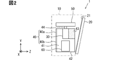
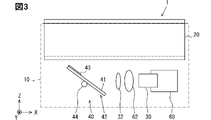
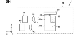
- the schematic diagram of the appearance of the laser radar apparatus 1 of embodiment The figure which shows the relative position of an optical system and a window 20 as seen from the II direction of FIG. The figure which shows the relative position of an optical system and a window 20 as seen from the direction III of FIG. The figure which shows the relative position of the component constituting an optical system as seen from the IV direction of FIG. Detailed block diagram of the mirror 40 of the embodiment.
- FIG. 9 is a diagram showing stray light regions 47a and 47b generated in the state of FIGS. 9 and 10.
- the figure explaining the inclination angle of the window 20 which suppresses the detection of a clutter.
- FIG. 1 is a schematic view of the appearance of the laser radar device 1 of the embodiment.
- the laser radar device 1 has a configuration including a housing 10 and a window 20.
- the housing 10 is provided with an opening into which the window 20 is fitted.
- the window 20 is fitted into the opening of the housing 10 in an inclined posture with respect to the flat plate-shaped back plate portion 11 facing the window 20 in the housing 10.
- the window 20 is light transmissive and has a flat plate and a rectangular shape.
- the laser radar device 1 irradiates the outside of the device with the laser beam L from the window 20.
- Glass can be used as the base material of the window 20.
- the base material of the window 20 may be a transparent resin.
- the laser radar device 1 irradiates the outside of the device while scanning the laser beam L.
- the direction vertically from the back plate portion 11 toward the window 20 is the front direction of the laser radar device 1. This direction is the Z direction.
- the plane orthogonal to the Z axis is the XY plane.
- the laser radar device 1 is attached to the vehicle and detects an object existing around the vehicle.
- One or more laser radar devices 1 are attached to the vehicle in order to detect an object existing around the vehicle.
- the laser radar device 1 can be attached to the vehicle in any posture.
- the positive direction of the Y-axis is the vehicle upward direction.
- the upward direction of the vehicle is simply referred to as the upward direction.
- FIG. 2 and 3 are diagrams illustrating the positions of the optical system provided inside the housing 10 and the window 20. In the figure below, the configurations other than those necessary for explanation are omitted as appropriate.
- FIG. 2 is a view seen from the direction II of FIG. 1
- FIG. 3 is a view seen from the direction III of FIG.
- FIG. 4 is a diagram showing the relative positions of the components constituting the optical system, and is a view seen from the IV direction of FIG.
- the inner surface of the device of the window 20 is coated with an antireflection film 21.
- the outer surface of the window 20 may also be coated with an antireflection film.
- the optical system includes a light source 30, a floodlight lens 32, a mirror 40, a motor 50, a detector 60, and a light receiving lens 62.
- the light source 30 emits laser light L, and a laser diode can be used.
- the laser beam L emitted by the light source 30 is directed toward the mirror 40.
- the projection lens 32 is provided between the light source 30 and the mirror 40, and suppresses the diffusion of the laser beam L.
- the mirror 40 includes a plate portion 42 in which one surface is a mirror surface 41.
- the mirror surface 41 has a rectangular shape, and a pair of short sides is parallel to the Z axis and a pair of long sides is parallel to the rotation axis 44.
- the pair of sides parallel to the Z axis may be the long side, and the pair of sides parallel to the rotation axis 44 may be the short side.
- the shape of the mirror surface 41 may be a square.
- a low reflection region 43 is formed on a part of the mirror surface 41.
- the upper portion in other words, the portion on the light source 30 side is the first mirror portion 40a that reflects the laser beam L emitted by the light source 30.
- the lower portion of the mirror 40 in other words, the portion on the detector 60 side is the second mirror portion 40b that reflects the laser beam L that has entered the inside of the device through the window 20 in the direction of the detector 60. ..
- the mirror 40 is a light emitting / receiving integrated type having a first mirror portion 40a and a second mirror portion 40b.
- the rotating shaft 44 is attached to the plate portion 42.
- the rotation axis 44 is parallel to the Y axis and is arranged at a position passing through the center of a pair of short sides facing each other of the plate portion 42.
- the rotary shaft 44 is integrated with the rotary shaft of the motor 50. Therefore, the mirror 40 is driven by the motor 50 and rotates about the rotation shaft 44 as the rotation center.
- the rotation is not limited to the rotation of 360 degrees, but also includes the rotation in an angle range narrower than 360 degrees such as 120 degrees and 150 degrees. Rotation of the mirror 40 in an angle range narrower than 360 degrees means that the mirror 40 reciprocates.
- a part of the laser beam L reflected by an object outside the device is incident on the inside of the device through the window 20, reflected by the mirror 40, and heads toward the detector 60.
- the detector 60 is arranged below the light source 30 in the Y-axis direction. Further, the light source 30 and the detector 60 are arranged on the same plane parallel to the XY plane. A photodiode can be used for the detector 60.
- the light receiving lens 62 is arranged between the mirror 40 and the detector 60 in the direction in which the laser beam L incident on the inside of the device from the outside of the device and reflected by the mirror 40 is directed.
- the light receiving lens 62 is a lens that collects laser light from the mirror 40 toward the detector 60.
- the window 20 has an inclined posture in which the distance from the rotating shaft 44 is shorter on the detector 60 side than on the light source 30 side.
- the distance here is the distance along the Z axis.
- FIG. 5 shows a detailed configuration of the mirror 40 of the present embodiment.
- the plate portion 42 of the mirror 40 has a structure in which a plate glass 42a, an adhesive film 42b, a silver thin film 42c, and a protective film 42d are laminated in this order.
- the upper side surface of the protective film 42d is a mirror surface 41.
- the above-mentioned low reflection region 43 is formed on a part of the mirror surface 41.
- the low reflection region 43 is a region having a lower reflectance than the mirror surface 41.
- the low reflection region 43 can be formed, for example, by applying a matte paint to the region by screen printing or the like.
- the color of the paint is, for example, black.
- the low reflection region 43 can be said to be a region in which the reflection of light is suppressed more than the mirror surface 41 by absorbing or attenuating the irradiated light.
- the Z axis is the side of the rectangular mirror surface 41 whose Y-axis direction faces the light source 30. It is formed in a region whose direction is biased to one of a pair of long sides of the mirror surface 41.
- the position in the Y-axis direction is closer to the light source 30 than the detector 60, and the position in the Z-axis direction is the light source. It is located closer to the window 20 than the region where the laser beam L emitted by 30 emits first.
- the state in which the mirror surface 41 of the mirror 40 faces the light source 30 is a state in which the laser beam L emitted by the light source 30 directly hits the mirror 40.
- FIG. 6 shows the path of the laser beam L when the stray light to be suppressed by the low reflection region 43 is generated.
- the laser beam L emitted by the light source 30 passes through the projection lens 32 and then hits the mirror 40.
- the laser light L emitted by the light source 30 and the laser light L radiated to the outside of the apparatus is referred to as a projection beam.
- the projected light beam reflected by the mirror 40 is reflected by the window 20, re-reflected by the mirror 40, exits from the window 20 to the outside of the device, and then reflected by an object outside the device to receive the light received by the detector 60. Make it a stray light. When simply described as stray light, it means the laser light L detected by the detector 60 in this path.
- the projected light beam reflected by the mirror 40 is reflected by the window 20 and re-reflected by the mirror 40 to go out of the device from the window 20, the projected light beam is from the region where the light beam first hits the mirror 40. However, the region where the projected beam hits the mirror 40 at the time of rereflection is closer to the window 20.
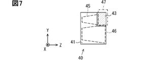
- FIG. 7 conceptually shows a light projecting area 45 in which the light projecting beam hits the mirror 40 and a light receiving area 46 in which the light receiving beam hits the mirror 40.
- the received beam means the laser beam L that the projected beam is reflected by an object outside the device and enters the inside of the device again.
- FIG. 7 shows a state in which the mirror 40 is tilted with respect to the optical axis of the floodlight beam.
- the left side of the figure is closer to the light source 30 than the right side of the figure. Therefore, the floodlight region 45 is trapezoidal.
- the light receiving region 46 is also trapezoidal because the mirror 40 shown in FIG. 7 is closer to the detector 60 on the left side of the figure than on the right side of the figure.
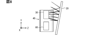
- FIG. 8 shows the traveling direction when the projection beam traveling in various directions is reflected by the window 20.
- the low reflection region 43 is omitted.
- the floodlight beam shown in FIG. 8 is a part of the floodlight beam projected by the laser radar device 1.
- the range of the floodlight beam reflected by the window 20 in the Y-axis direction is a range that partially overlaps the range of the floodlight beam toward the window 20.
- the low reflection region 43 is located on the light source 30 side in the Y-axis direction in the mirror 40. Further, the position of the low reflection region 43 in the radial direction of the rotation shaft 44 is closer to the window 20 when the mirror surface 41 faces the light source 30 side than the region where the light projection beam first hits the mirror 40. be.
- FIG. 9 is a diagram in which the incident angle of the laser beam L from the light source 30 incident on the mirror 40 is minimized when stray light is generated.
- FIG. 10 is a diagram in which the incident angle is maximized when stray light is generated.
- 9 and 10 are diagrams for explaining the rotation angle range of the mirror 40 in which stray light is generated.
- the window 20 is different from the laser radar device 1 of the embodiment. Not tilted.
- the projected light beam reflected by the window 20 and re-reflected by the mirror 40 passes through the end of the window 20 and exits the device.
- the projected light beam rereflected by the mirror 40 hits the frame of the window 20 and does not go out of the device.
- the projected light beam reflected by the window 20 hits the region closest to the window 20 in the mirror 40. If the incident angle of the laser beam L is further increased, the projected light beam reflected by the window 20 does not hit the mirror 40.
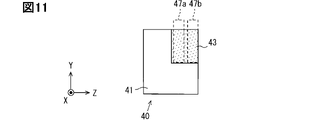
- FIG. 11 shows the positional relationship between the stray light region 47a generated in the state of FIG. 9 and the stray light region 47b generated in the state of FIG. 10 and the mirror 40.
- the stray light regions 47a and 47b mean regions where the projected light beam is reflected by the window 20 and hits the mirror 40 or passes in the vicinity of the mirror 40.
- the two stray light regions 47a and 47b shown in FIG. 11 and the region including between them are the stray light region 47 shown in FIG. 7.
- the stray light region 47 is a region where the stray light hits the mirror 40 or the stray light passes near the mirror 40 in the rotation angle range of the mirror 40 where the stray light is generated.
- the size of the low reflection region 43 is determined to include a range in which the stray light region 47 and the mirror surface 41 of the mirror 40 overlap.
- the stray light region 47 shown in FIG. 7 has a region deviating from the mirror surface 41.
- the region deviated from the mirror surface 41 is larger when the window 20 is tilted as in the present embodiment as compared with the case where the window 20 is not tilted.
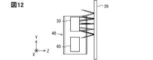
- FIG. 12 shows the direction in which the projected light beam reflected by the window 20 heads when the window 20 is not tilted.
- the direction in which the projected light beam reflected by the window 20 is directed is larger when the window 20 is tilted than when the window 20 is not tilted. Is upward on the Y axis.
- FIG. 13 shows changes in the positions of the stray light regions 47a and 47b with respect to the mirror 40 when the inclination of the window 20 is changed.
- the angle in parentheses is the tilt angle of the window 20 with respect to the XY plane.
- the stray light region 47 moves upward relative to the mirror 40 as compared with the case where the window 20 is not tilted. Further, when the window 20 is tilted, the stray light region 47 moves in the direction of the window 20 relative to the mirror 40 as compared with the case where the window 20 is not tilted.
- the stray light region 47 partially overlaps the light projection region 45 and the light receiving region 46. Therefore, the low reflection region 43 formed so as to include the stray light region 47 also partially overlaps the light projection region 45 and the light receiving region 46. As the stray light region 47 moves upward and to the right in FIG. 7, the low reflection region 43 becomes smaller. When the low reflection area 43 becomes small, the overlapping area between the low reflection area 43, the light projecting area 45, and the light receiving area 46 becomes small. When the overlapping region between the low reflection region 43, the projection region 45, and the light receiving region 46 becomes small, the degree to which the normal laser beam L is weakened in the low reflection region 43 is reduced. As a result, the SN ratio is improved.
- the low reflection region 43 is formed in the first mirror portion 40a of the mirror 40.
- the region where the low reflection region 43 is formed is a region where the stray light hits the mirror 40. Therefore, the laser radar device 1 can suppress the detection of stray light.
- the window 20 has an inclined posture in which the distance from the rotation shaft 44 is shorter on the detector 60 side than on the light source 30 side.
- the low reflection region 43 can be made smaller than when the window 20 is not tilted, that is, when the distance from the window 20 to the rotation axis 44 is equal on the light source 30 side and the detector 60 side. ..
- the normal laser beam L which is not stray light, is less likely to be weakened in the low reflection region 43, so that the SN ratio can be improved.
- the antireflection film 21 is provided on the inner side surface of the device of the window 20, the degree to which the laser beam L is reflected on the inner side surface of the device of the window 20 to generate stray light is suppressed.
- FIG. 14 shows the laser radar device 200 of the second embodiment.
- the shape of the mirror 240 is different from that of the mirror 40 of the first embodiment.
- the mirror 240 includes a first mirror portion 240a and a second mirror portion 240b.
- the first mirror portion 240a has the same shape as the first mirror portion 40a of the first embodiment.
- the shape of the second mirror portion 240b is different from that of the second mirror portion 40b of the first embodiment.
- the length of the second mirror portion 240b in the radial direction of the rotating shaft 44 becomes shorter toward the lower side in FIG. 14, that is, toward the side opposite to the first mirror portion 240a. Therefore, in the second mirror portion 240b, both sides on the radial outer side of the rotating shaft 44 are inclined side portions 244 that are closer to the rotating shaft 44 toward the end on the detector 60 side.
- the inclined side portion 244 is parallel to the window 20. Being parallel to the window 20 is an example of a state along the window 20.
- the state in which the inclined side portion 244 is along the window 20 includes a state in which the inclined side portion 244 is completely parallel to the window 20 as well as a state in which the inclined side portion 244 is almost parallel to the window 20.
- the radial outer side of the rotating shaft 44 is a parallel side portion 245 parallel to the rotating shaft 44.
- the mirror surface 241 of the mirror 240 having such a shape has a line symmetry shape with the rotation axis 44 as the axis of symmetry as a whole.
- the mirror 240 includes an inclined side portion 244, and the distance between the window 20 and the optical system component such as the mirror 240 in the second embodiment is larger than the distance between the window 20 and the optical system component such as the mirror 40 in the first embodiment. It's getting closer. The distance between the window 20 and the mirror 240 is so close that the mirror 240 hits the window 20 if the parallel side portion 245 extends to the end of the mirror 240 on the detector 60 side.
- the low reflection region 243 included in the mirror 240 of the second embodiment can be made smaller than the low reflection region 43 included in the mirror 40 of the first embodiment. Since the low reflection region 243 can be made small, the SN ratio can be improved.
- the mirror surface 241 of the mirror 240 has a line-symmetrical shape with the rotation axis 44 as the axis of symmetry. As a result, the center of gravity of the mirror 240 is on the rotation shaft 44, so that vibration when the mirror 240 is rotated can be suppressed.
- a laser radar device for preventing clutter will be described. Unlike the stray light described so far, the clutter in the third embodiment is different from the stray light described so far. This is the laser beam L that is reflected by the detector 60 and detected by the detector 60.
- the window 20 is tilted to prevent clutter from being detected.
- FIG. 15 will be used to explain the inclination angle of the window 20 that suppresses the detection of clutter.
- the optical path between the light source 30 and the detector 60 and the window 20 is a straight line for the sake of clarity.
- FIG. 15 describes that the light source 30 is at the position of the alternate long and short dash line shown in FIG.
- the position of the light source 30 indicated by the two-dot chain line is on a straight line including the direction in which the laser beam L reflected by the mirror 40 is directed.
- clutter can occur when the mirror 40 reflects the projected beam in the 0 ° direction of the Z coordinate. Therefore, in the description of the clutter, the light source 30 which is actually located at the position of the solid line may be considered as being located at the position of the alternate long and short dash line.
- the window 20 indicated by the alternate long and short dash line is a non-tilted window 20.
- the laser beam L shown by the two-point chain line indicates the traveling direction when the laser beam L, which is most downward in the Y-axis direction among the projected beams from the light source 30, is reflected by the non-tilted window 20.
- the laser beam L shown by the solid line is also the laser beam L that is most downward in the Y-axis direction among the projected beams from the light source 30.
- the traveling direction of the laser beam L reflected by the inclined window 20 shown by the solid line is shown.
- the angle ⁇ is an angle between the direction in which the laser beam L indicated by the alternate long and short dash line travels and the direction in which the laser beam L indicated by the solid line travels. At this time, the inclination of the window 20 becomes ⁇ / 2.
- the inclination of the window 20 is made larger than ⁇ / 2.
- the inclination of the window 20 is such that the laser beam L directed toward the detector 60 among the laser beams L irradiated by the light source 30 passes closer to the light source 30 than the detector 60, and the detector. Not incident on 60. Therefore, the clutter is not detected by the detector 60.
- ⁇ Modification 1> 17 to 19 show other examples of the configuration of the mirrors 340, 440, and 540.
- the mirror 340 shown in FIG. 17 includes an aluminum thin film 42e in place of the adhesion film 42b and the silver thin film 42c provided in the mirror 40.
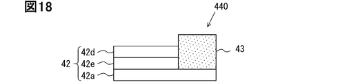
- the mirror 440 shown in FIG. 18 also includes a plate glass 42a, an aluminum thin film 42e, a protective film 42d, and a low reflection region 43. However, it differs from the mirror 340 in that the low reflection region 43 is directly laminated on the plate glass 42a.
- the mirror 540 uses a black resin plate 541 as a base material.
- An adhesive film 42b, an aluminum thin film 42e, and a protective film 42d are laminated in this order on the adhesive film 42b.
- a region in which the adhesive films 42b and the like are not laminated is partially formed. That region becomes the low reflection region 543.
- the mirror 40 had a line-symmetrical shape including two inclined side portions 244 having the same length and inclination. However, the length and inclination of the two inclined side portions 244 may be different from each other.
- the parallel side portion 245 may be shorter and the inclined side portion 244 may be longer than in the embodiment. Further, the parallel side portion 245 may not be provided, and the end of the light source 30 side to the end of the detector 60 may be an inclined side portion 244.
Landscapes
- Physics & Mathematics (AREA)
- Engineering & Computer Science (AREA)
- General Physics & Mathematics (AREA)
- Radar, Positioning & Navigation (AREA)
- Remote Sensing (AREA)
- Computer Networks & Wireless Communication (AREA)
- Electromagnetism (AREA)
- Optics & Photonics (AREA)
- Optical Radar Systems And Details Thereof (AREA)
- Measurement Of Optical Distance (AREA)
- Mechanical Optical Scanning Systems (AREA)
Priority Applications (3)
| Application Number | Priority Date | Filing Date | Title |
|---|---|---|---|
| DE112021005826.6T DE112021005826T5 (de) | 2020-11-06 | 2021-10-25 | Laserradargerät |
| CN202180070474.1A CN116324481B (zh) | 2020-11-06 | 2021-10-25 | 激光雷达装置 |
| US18/178,607 US20230221417A1 (en) | 2020-11-06 | 2023-03-06 | Laser radar device |
Applications Claiming Priority (2)
| Application Number | Priority Date | Filing Date | Title |
|---|---|---|---|
| JP2020185920A JP7424273B2 (ja) | 2020-11-06 | 2020-11-06 | レーザレーダ装置 |
| JP2020-185920 | 2020-11-06 |
Related Child Applications (1)
| Application Number | Title | Priority Date | Filing Date |
|---|---|---|---|
| US18/178,607 Continuation US20230221417A1 (en) | 2020-11-06 | 2023-03-06 | Laser radar device |
Publications (1)
| Publication Number | Publication Date |
|---|---|
| WO2022097518A1 true WO2022097518A1 (ja) | 2022-05-12 |
Family
ID=81457818
Family Applications (1)
| Application Number | Title | Priority Date | Filing Date |
|---|---|---|---|
| PCT/JP2021/039250 Ceased WO2022097518A1 (ja) | 2020-11-06 | 2021-10-25 | レーザレーダ装置 |
Country Status (5)
| Country | Link |
|---|---|
| US (1) | US20230221417A1 (cg-RX-API-DMAC7.html) |
| JP (1) | JP7424273B2 (cg-RX-API-DMAC7.html) |
| CN (1) | CN116324481B (cg-RX-API-DMAC7.html) |
| DE (1) | DE112021005826T5 (cg-RX-API-DMAC7.html) |
| WO (1) | WO2022097518A1 (cg-RX-API-DMAC7.html) |
Families Citing this family (1)
| Publication number | Priority date | Publication date | Assignee | Title |
|---|---|---|---|---|
| US20250076465A1 (en) * | 2023-09-05 | 2025-03-06 | Stmicroelectronics International N.V. | Retroreflective mechanisms on optical ranging, proximity, and image sensors to reduce optical noise from unwanted sources |
Citations (7)
| Publication number | Priority date | Publication date | Assignee | Title |
|---|---|---|---|---|
| JP2009063339A (ja) * | 2007-09-05 | 2009-03-26 | Hokuyo Automatic Co | 走査式測距装置 |
| JP2017097203A (ja) * | 2015-11-26 | 2017-06-01 | 船井電機株式会社 | 光走査装置 |
| JP2019152588A (ja) * | 2018-03-06 | 2019-09-12 | オムロンオートモーティブエレクトロニクス株式会社 | 対象物検出装置 |
| JP2020508457A (ja) * | 2017-03-29 | 2020-03-19 | エスゼット ディージェイアイ テクノロジー カンパニー リミテッドSz Dji Technology Co.,Ltd | センサーシステム及びその方法 |
| WO2020090592A1 (ja) * | 2018-10-29 | 2020-05-07 | 日本電気株式会社 | センサ装置及び物品陳列棚 |
| WO2020149241A1 (ja) * | 2019-01-15 | 2020-07-23 | 株式会社デンソー | 光走査装置 |
| WO2020205109A1 (en) * | 2019-03-29 | 2020-10-08 | Omron Corporation | Visual indicators for presence sensing systems |
Family Cites Families (10)
| Publication number | Priority date | Publication date | Assignee | Title |
|---|---|---|---|---|
| JP4720852B2 (ja) * | 2008-05-14 | 2011-07-13 | ソニー株式会社 | ミラー駆動装置および撮像装置 |
| JP5532003B2 (ja) * | 2011-03-31 | 2014-06-25 | 株式会社デンソーウェーブ | レーザレーダ装置 |
| CN107238827B (zh) * | 2016-03-29 | 2021-04-27 | 莱卡地球系统公开股份有限公司 | 激光扫描器装置 |
| US9964437B2 (en) * | 2016-05-03 | 2018-05-08 | Datalogic IP Tech, S.r.l. | Laser scanner with reduced internal optical reflection comprising a light detector disposed between an interference filter and a collecting mirror |
| JP2019138675A (ja) | 2018-02-07 | 2019-08-22 | オムロンオートモーティブエレクトロニクス株式会社 | 対象物検出装置 |
| CN109581328B (zh) * | 2018-12-21 | 2023-06-02 | 宁波傲视智绘光电科技有限公司 | 一种激光雷达 |
| CN209433005U (zh) * | 2019-01-07 | 2019-09-24 | 武汉海达数云技术有限公司 | 一种激光雷达及消杂光装置 |
| US11422237B2 (en) * | 2019-01-15 | 2022-08-23 | Seagate Technology Llc | Pyramidal mirror laser scanning for lidar |
| CN110133618B (zh) * | 2019-04-19 | 2021-08-17 | 深圳市速腾聚创科技有限公司 | 激光雷达及探测方法 |
| JP7318304B2 (ja) | 2019-05-15 | 2023-08-01 | 株式会社ジェイテクト | 操舵制御装置 |
-
2020
- 2020-11-06 JP JP2020185920A patent/JP7424273B2/ja active Active
-
2021
- 2021-10-25 DE DE112021005826.6T patent/DE112021005826T5/de active Pending
- 2021-10-25 CN CN202180070474.1A patent/CN116324481B/zh active Active
- 2021-10-25 WO PCT/JP2021/039250 patent/WO2022097518A1/ja not_active Ceased
-
2023
- 2023-03-06 US US18/178,607 patent/US20230221417A1/en active Pending
Patent Citations (7)
| Publication number | Priority date | Publication date | Assignee | Title |
|---|---|---|---|---|
| JP2009063339A (ja) * | 2007-09-05 | 2009-03-26 | Hokuyo Automatic Co | 走査式測距装置 |
| JP2017097203A (ja) * | 2015-11-26 | 2017-06-01 | 船井電機株式会社 | 光走査装置 |
| JP2020508457A (ja) * | 2017-03-29 | 2020-03-19 | エスゼット ディージェイアイ テクノロジー カンパニー リミテッドSz Dji Technology Co.,Ltd | センサーシステム及びその方法 |
| JP2019152588A (ja) * | 2018-03-06 | 2019-09-12 | オムロンオートモーティブエレクトロニクス株式会社 | 対象物検出装置 |
| WO2020090592A1 (ja) * | 2018-10-29 | 2020-05-07 | 日本電気株式会社 | センサ装置及び物品陳列棚 |
| WO2020149241A1 (ja) * | 2019-01-15 | 2020-07-23 | 株式会社デンソー | 光走査装置 |
| WO2020205109A1 (en) * | 2019-03-29 | 2020-10-08 | Omron Corporation | Visual indicators for presence sensing systems |
Also Published As
| Publication number | Publication date |
|---|---|
| US20230221417A1 (en) | 2023-07-13 |
| CN116324481B (zh) | 2025-12-23 |
| DE112021005826T5 (de) | 2023-08-24 |
| JP7424273B2 (ja) | 2024-01-30 |
| CN116324481A (zh) | 2023-06-23 |
| JP2022075248A (ja) | 2022-05-18 |
Similar Documents
| Publication | Publication Date | Title |
|---|---|---|
| US20240085564A1 (en) | LIDAR Systems with Multi-faceted Mirrors | |
| JP6737296B2 (ja) | 対象物検出装置 | |
| JP3333054B2 (ja) | レーザ距離測定装置 | |
| JPH0815413A (ja) | 距離測定装置 | |
| WO2024066524A1 (zh) | 激光雷达和汽车 | |
| US12578437B2 (en) | Distance measuring apparatus | |
| JPH1082851A (ja) | レーザ距離測定装置 | |
| WO2017135225A1 (ja) | 光走査型の対象物検出装置 | |
| WO2022097518A1 (ja) | レーザレーダ装置 | |
| US6879447B2 (en) | Optical gimbal apparatus | |
| JP2020190495A (ja) | 距離測定装置 | |
| JP6676974B2 (ja) | 対象物検出装置 | |
| US10746856B2 (en) | Light scanning type object detecting device | |
| JP7505422B2 (ja) | 光検出装置 | |
| US20240329204A1 (en) | Distance measuring apparatus | |
| JP3463781B2 (ja) | レーザ距離測定装置 | |
| JP2019152588A (ja) | 対象物検出装置 | |
| WO2017065049A1 (ja) | 光走査型の対象物検出装置 | |
| JP2020148618A (ja) | 対象物検出装置 | |
| WO2024154457A1 (ja) | 光学センサ | |
| JP2020148617A (ja) | 対象物検出装置 | |
| JP2018054325A (ja) | レーザレーダ装置 | |
| WO2021019903A1 (ja) | レーザレーダ |
Legal Events
| Date | Code | Title | Description |
|---|---|---|---|
| 121 | Ep: the epo has been informed by wipo that ep was designated in this application |
Ref document number: 21889071 Country of ref document: EP Kind code of ref document: A1 |
|
| 122 | Ep: pct application non-entry in european phase |
Ref document number: 21889071 Country of ref document: EP Kind code of ref document: A1 |