WO2022097417A1 - 熱拡散デバイス - Google Patents
熱拡散デバイス Download PDFInfo
- Publication number
- WO2022097417A1 WO2022097417A1 PCT/JP2021/037140 JP2021037140W WO2022097417A1 WO 2022097417 A1 WO2022097417 A1 WO 2022097417A1 JP 2021037140 W JP2021037140 W JP 2021037140W WO 2022097417 A1 WO2022097417 A1 WO 2022097417A1
- Authority
- WO
- WIPO (PCT)
- Prior art keywords
- wick
- wall surface
- region
- housing
- heat diffusion
- Prior art date
- Legal status (The legal status is an assumption and is not a legal conclusion. Google has not performed a legal analysis and makes no representation as to the accuracy of the status listed.)
- Ceased
Links
Images




Classifications
-
- F—MECHANICAL ENGINEERING; LIGHTING; HEATING; WEAPONS; BLASTING
- F28—HEAT EXCHANGE IN GENERAL
- F28D—HEAT-EXCHANGE APPARATUS, NOT PROVIDED FOR IN ANOTHER SUBCLASS, IN WHICH THE HEAT-EXCHANGE MEDIA DO NOT COME INTO DIRECT CONTACT
- F28D15/00—Heat-exchange apparatus with the intermediate heat-transfer medium in closed tubes passing into or through the conduit walls ; Heat-exchange apparatus employing intermediate heat-transfer medium or bodies
- F28D15/02—Heat-exchange apparatus with the intermediate heat-transfer medium in closed tubes passing into or through the conduit walls ; Heat-exchange apparatus employing intermediate heat-transfer medium or bodies in which the medium condenses and evaporates, e.g. heat pipes
-
- F—MECHANICAL ENGINEERING; LIGHTING; HEATING; WEAPONS; BLASTING
- F28—HEAT EXCHANGE IN GENERAL
- F28D—HEAT-EXCHANGE APPARATUS, NOT PROVIDED FOR IN ANOTHER SUBCLASS, IN WHICH THE HEAT-EXCHANGE MEDIA DO NOT COME INTO DIRECT CONTACT
- F28D15/00—Heat-exchange apparatus with the intermediate heat-transfer medium in closed tubes passing into or through the conduit walls ; Heat-exchange apparatus employing intermediate heat-transfer medium or bodies
- F28D15/02—Heat-exchange apparatus with the intermediate heat-transfer medium in closed tubes passing into or through the conduit walls ; Heat-exchange apparatus employing intermediate heat-transfer medium or bodies in which the medium condenses and evaporates, e.g. heat pipes
- F28D15/04—Heat-exchange apparatus with the intermediate heat-transfer medium in closed tubes passing into or through the conduit walls ; Heat-exchange apparatus employing intermediate heat-transfer medium or bodies in which the medium condenses and evaporates, e.g. heat pipes with tubes having a capillary structure
Definitions
- the present invention relates to a heat diffusion device.
- the vapor chamber has a structure in which a working medium and a wick that transports the working medium by capillary force are enclosed inside the housing.
- the working medium absorbs heat from the heat generating element in the evaporation unit that absorbs heat from the heat generating element and evaporates in the vapor chamber, then moves in the vapor chamber, is cooled, and returns to the liquid phase.
- the working medium that has returned to the liquid phase moves to the evaporation part on the heat generating element side again by the capillary force of the wick, and cools the heat generating element.
- the vapor chamber operates independently without having external power, and can diffuse heat two-dimensionally at high speed by utilizing the latent heat of vaporization and the latent heat of condensation of the working medium.
- Patent Document 1 includes a flat container in which a working fluid is enclosed and a wick provided inside the container.
- the wick includes a braided body in which fibers are knitted into a tubular shape and the above. It has a linear bundle in which fibers thicker than the fiber are bundled linearly, and the linear bundle is arranged in a cavity surrounded by an inner peripheral surface of the braid, and is arranged around the braid.
- a heat pipe characterized in that a vapor flow path of the working fluid is formed and a liquid flow path of the working fluid is formed in the cavity.
- Patent No. 669499 Japanese Unexamined Patent Publication No. 2018-76989 (Patent No. 669499)
- the inner region and the outer region are formed in the wick by changing the thickness of the fiber used as the material of the wick, and then the inner region is the liquid flow path and the outer region is the steam flow. It's a road.
- Patent Document 1 does not disclose or suggest how to effectively arrange the wick with respect to the heat source.
- the above problem is not limited to the vapor chamber, but is a problem common to heat diffusion devices capable of diffusing heat by the same configuration as the vapor chamber.
- An object of the present invention is to provide a heat diffusion device in which a circulation path of an operating medium is secured and air and liquid can be easily exchanged. It is also an object of the present invention to provide an electronic device provided with the heat diffusion device.
- the heat diffusion device of the present invention has a housing having a first inner wall surface and a second inner wall surface facing each other in the thickness direction, an actuating medium enclosed in the internal space of the housing, and the first of the housing. It comprises at least one wick, which is arranged between the inner wall surface and the second inner wall surface. The wick extends from the first end to the second end in a plan view of the first inner wall surface from the thickness direction.
- the wick is composed of a fiber bundle in which fibers are bundled linearly. When looking at the cross section along the extending direction and the thickness direction of the wick, the first end of the wick is located in the first region of the housing, and the first end of the wick and the second end of the wick are located.
- a part excluding the end is located in a second region different from the first region of the housing.
- the wick has a first portion in the first region that is in contact with the first inner wall surface and not in contact with the second inner wall surface, and in the second region, the first inner wall surface and the second inner wall surface. Has a second portion in contact with.
- the electronic device of the present invention includes the heat diffusion device of the present invention.
- FIG. 1 is a perspective view schematically showing an example of a vapor chamber according to the first embodiment of the present invention.
- FIG. 2 is a cross-sectional view taken along the line II-II of the vapor chamber shown in FIG.
- FIG. 3 is a cross-sectional view taken along the line III-III of the vapor chamber shown in FIG.
- FIG. 4 is an enlarged view of the portion shown by IV in FIG.
- FIG. 5 is an enlarged view of the portion indicated by V in FIG. 2.
- FIG. 6 is a cross-sectional view taken along the line VI-VI of Wick shown in FIG.
- FIG. 7 is an enlarged view of the vicinity of the evaporation portion shown in FIG.
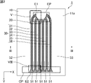
- FIG. 8 is an enlarged view of the portion shown by VIII in FIG. FIG.
- FIG. 9 is a cross-sectional view taken along the line IX-IX of the wick shown in FIG.
- FIG. 10 is a plan view schematically showing an example of the vapor chamber according to the second embodiment of the present invention.
- FIG. 11 is a plan view schematically showing another example of the vapor chamber according to the second embodiment of the present invention.
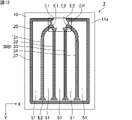
- FIG. 12 is a plan view schematically showing an example of the vapor chamber according to the third embodiment of the present invention.
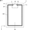
- FIG. 13 is a plan view schematically showing an example of the vapor chamber according to the fourth embodiment of the present invention.
- the present invention is not limited to the following embodiments, and can be appropriately modified and applied without changing the gist of the present invention. It should be noted that a combination of two or more of the individual preferable configurations described below is also the present invention.
- heat diffusion device of the present invention when each embodiment is not particularly distinguished, it is simply referred to as "heat diffusion device of the present invention".
- a vapor chamber will be described as an example of an embodiment of the heat diffusion device of the present invention.
- the heat diffusion device of the present invention can also be applied to a heat diffusion device such as a heat pipe.
- FIG. 1 is a perspective view schematically showing an example of a vapor chamber according to the first embodiment of the present invention.
- FIG. 2 is a cross-sectional view taken along the line II-II of the vapor chamber shown in FIG.
- FIG. 3 is a cross-sectional view taken along the line III-III of the vapor chamber shown in FIG.
- the vapor chamber 1 shown in FIG. 1 includes a hollow housing 10 that is hermetically sealed. As shown in FIG. 3, the housing 10 has a first inner wall surface 11a and a second inner wall surface 12a facing each other in the thickness direction Z. As shown in FIGS. 2 and 3, the vapor chamber 1 is further divided between the working medium 20 enclosed in the internal space of the housing 10 and the first inner wall surface 11a and the second inner wall surface 12a of the housing 10. It comprises a plurality of wicks 30 arranged in. In this embodiment, the plurality of wicks 30 include, for example, six wicks 31, 32, 33, 34, 35 and 36.
- the housing 10 is provided with an evaporation unit EP that evaporates the enclosed working medium 20. Further, the housing 10 may be set with a condensation portion CP for condensing the evaporated working medium 20.
- a heat source HS which is a heat generating element, is arranged on the outer wall surface of the housing 10. Examples of the heat source HS include electronic components of electronic devices, such as a central processing unit (CPU).
- CPU central processing unit
- the portion near the heat source HS and heated by the heat source HS corresponds to the evaporation portion EP.
- the portion away from the evaporation portion EP corresponds to the condensation portion CP.
- the evaporated working medium 20 can be condensed other than the condensed portion CP. In the present embodiment, a portion where the evaporated working medium 20 is particularly easy to condense is expressed as a condensing portion CP.
- the vapor chamber 1 is planar as a whole. That is, the housing 10 is planar as a whole.
- the "plane” includes a plate shape and a sheet shape, and the dimension in the width direction X (hereinafter referred to as "width") and the dimension in the length direction Y (hereinafter referred to as “length”) are in the thickness direction Z. It means a shape that is considerably larger than a dimension (hereinafter referred to as thickness or height), for example, a shape having a width and a length of 10 times or more, preferably 100 times or more the thickness.
- the size of the vapor chamber 1, that is, the size of the housing 10 is not particularly limited.
- the width and length of the vapor chamber 1 can be appropriately set according to the intended use.
- the width and length of the vapor chamber 1 are, for example, 5 mm or more and 500 mm or less, 20 mm or more and 300 mm or less, or 50 mm or more and 200 mm or less, respectively.
- the width and length of the vapor chamber 1 may be the same or different.
- the housing 10 is composed of the first sheet 11 and the second sheet 12 facing each other to which the outer edges are joined.
- the materials constituting the first sheet 11 and the second sheet 12 are not particularly limited as long as they have properties suitable for use as a vapor chamber, such as thermal conductivity, strength, flexibility, and flexibility.
- the material constituting the first sheet 11 and the second sheet 12 is preferably a metal, for example, copper, nickel, aluminum, magnesium, titanium, iron, or an alloy containing them as a main component, and particularly preferably copper. Is.
- the materials constituting the first sheet 11 and the second sheet 12 may be the same or different, but are preferably the same.
- the housing 10 is composed of the first sheet 11 and the second sheet 12
- the first sheet 11 and the second sheet 12 are joined to each other at their outer edges.
- the joining method is not particularly limited, but for example, laser welding, resistance welding, diffusion welding, brazing, TIG welding (tungsten-inert gas welding), ultrasonic welding, or resin encapsulation can be used, and is preferable.
- TIG welding tungsten-inert gas welding
- ultrasonic welding or resin encapsulation
- resin encapsulation can be used, and is preferable.
- the thicknesses of the first sheet 11 and the second sheet 12 are not particularly limited, but are preferably 10 ⁇ m or more and 200 ⁇ m or less, more preferably 30 ⁇ m or more and 100 ⁇ m or less, and further preferably 40 ⁇ m or more and 60 ⁇ m or less, respectively.
- the thicknesses of the first sheet 11 and the second sheet 12 may be the same or different. Further, the thickness of each of the first sheet 11 and the second sheet 12 may be the same throughout, or a part thereof may be thin.
- the shapes of the first sheet 11 and the second sheet 12 are not particularly limited.
- the first sheet 11 has a flat plate shape having a constant thickness
- the second sheet 12 has a shape in which the outer edge portion is thicker than the portion other than the outer edge portion.
- the first sheet 11 has a flat plate shape having a constant thickness and the second sheet 12 has a constant thickness and a portion other than the outer edge portion is convex outward with respect to the outer edge portion.
- a dent is formed on the outer edge of the housing 10. Therefore, the dent on the outer edge can be used when mounting the vapor chamber. Further, other parts and the like can be arranged in the recess of the outer edge portion.
- the thickness of the entire vapor chamber 1 is not particularly limited, but is preferably 50 ⁇ m or more and 500 ⁇ m or less.
- the working medium 20 is not particularly limited as long as it can cause a gas-liquid phase change in the environment inside the housing 10, and for example, water, alcohols, CFC substitutes, or the like can be used.
- the working medium is an aqueous compound, preferably water.
- the wicks 31, 32, 33, 34, 35 and 36 which are examples of the plurality of wicks 30, are parallel to each other in a plan view from the thickness direction Z of the first inner wall surface 11a. As such, it extends from the first end E1 to the second end E2.
- six wicks are included as the plurality of wicks 30, but the number of wicks 30 is not particularly limited as long as it is two or more.
- the wick 30 such as the wick 31 is in contact with the first inner wall surface 11a and the second inner wall surface 12a.
- These wicks 30 may be in contact with either the first inner wall surface 11a or the second inner wall surface 12a, or may not be in contact with the first inner wall surface 11a and the second inner wall surface 12a.
- FIG. 4 is an enlarged view of the portion shown by IV in FIG.
- the wick 30 such as the wick 31 is composed of a fiber bundle in which fibers F are bundled linearly. These fiber bundles function as wicks that transport the working medium 20 by capillary force. Therefore, the working medium 20 that has evaporated in the evaporation unit EP and condensed in the condensation unit CP, for example, can be returned to the evaporation unit EP again.
- a metal wire such as copper, aluminum, or stainless steel, or a non-metal wire such as carbon fiber or glass fiber can be used.
- metal wire is preferable because it has high thermal conductivity.
- a fiber bundle can be obtained by bundling about 200 copper wires having a diameter of about 0.03 mm.
- the wick 30 such as the wick 31 is fixed to either or both of the first inner wall surface 11a and the second inner wall surface 12a of the housing 10.
- the wick 30 such as the wick 31 is joined to one or both of the first inner wall surface 11a and the second inner wall surface 12a of the housing 10.
- the joining method is not particularly limited, but for example, spot welding, diffusion joining, or the like can be used.
- the cross section of the fiber F perpendicular to the direction in which the wick 30 such as the wick 31 extends is preferably flat.
- the cross section of the fiber F is flat, even if the wick 30 is thin, the fiber F does not fill tightly and a gap between the fibers F is secured, so that a sufficient liquid flow path can be secured.
- the contact area with the housing 10 increases and the fixing strength increases, so that the structure is strong against external stress such as bending. As a result, a vapor chamber having excellent liquid circulation, liquid transport capacity, and reliability against external stress can be obtained.
- the aspect ratio (a / b) defined by the ratio of the major axis a and the minor axis b of the fiber F in the cross section is 1.1. It is preferably more than or equal to, and preferably 2 or less.
- the wicks 31, 32, 33, 34, 35 and 36 each extend to the wall surface of the housing 10 located below the evaporation unit EP.
- the wick 30 such as the wick 31 is arranged so as to be concentrated in the lower portion of the evaporation portion EP.
- the first steam flow path 51 is formed between the adjacent wicks 30.
- the width between the outermost wick 30 (wick 31 in FIGS. 2 and 3) and the housing 10 among the plurality of wicks 30 is wider than that of the first steam flow path 51.
- the second steam flow path 52 is formed.
- a third steam flow path 53 wider than the first steam flow path 51 is formed between the other wick 30 (wick 36 in FIGS. 2 and 3) located on the outermost side and the housing 10. It is preferable that it is.
- the formation region of the second steam flow path 52 and the third steam flow path 53 is preferably 60% or more of the formation region of the entire steam flow path.
- the wicks 30 such as the wicks 31 are unevenly distributed in a part, the steam of the working medium 20 does not pass through the part, so that the heat equalizing performance of the entire vapor chamber deteriorates. Therefore, by providing a gap between the wicks 30 and using the gap as a steam flow path, the heat soaking performance can be improved. As a result, a vapor chamber having excellent liquid circulation and vapor circulation, and high liquid transport capacity and soaking performance can be obtained.
- the width of the first steam flow path 51 is preferably 300 ⁇ m or more and 3000 ⁇ m or less, and more preferably 1000 ⁇ m or more and 2000 ⁇ m or less. In the cross section shown in FIG. 3, when the width of the first steam flow path 51 is different in the thickness direction Z, the width of the widest portion is defined as the width of the first steam flow path 51.
- the width of the second steam flow path 52 is larger than the width of the first steam flow path 51.
- the width of the second steam flow path 52 is preferably 5 mm or more, and more preferably 10 mm or more.
- the width of the widest portion is defined as the width of the second steam flow path 52.
- the width of the third steam flow path 53 is larger than the width of the first steam flow path 51.
- the width of the third steam flow path 53 is preferably 5 mm or more, and more preferably 10 mm or more.
- the width of the widest portion is defined as the width of the second steam flow path 52.
- the width of the third steam flow path 53 may be the same as or different from the width of the second steam flow path 52.
- FIG. 5 is an enlarged view of the portion indicated by V in FIG. 2.
- FIG. 6 is a cross-sectional view taken along the line VI-VI of Wick shown in FIG.
- the first end E1 of the wick 30 such as the wick 31 is the first region of the housing 10.
- a part of the wick 30 other than the first end E1 and the second end E2 located in R1 is located in a second region R2 different from the first region R1 of the housing 10.
- the wick 30 such as the wick 31 has a first portion P1 in the first region R1 that is in contact with the first inner wall surface 11a and not in contact with the second inner wall surface 12a, and in the second region R2, the first inner wall surface 11a and It has a second portion P2 in contact with the second inner wall surface 12a.
- At least one wick may have the first portion P1, but it is preferable that all the wicks 30 have the first portion P1.
- the first region R1 is preferably located in the evaporation unit EP.
- the first portion P1 is thinner than the second portion P2.
- the thinned first portion P1 increases the area of the portion where the steam of the working medium 20 evaporates, so that a circulation path can be secured.
- the wick 30 such as the wick 31 may have the first portion P1 somewhere in the first region R1, but the first portion P1 of the wick 30 is the first portion of the wick 30 as shown in FIG. It is preferable to include the end E1.
- the first portion P1 of the wick 30 such as the wick 31 is thicker than the second portion P2 of the wick 30.
- the first portion P1 thicker than the second portion P2 of the wick 30.
- the evaporation area becomes wider, so that the exchange of gas and liquid becomes smooth.
- the first portion P1 may be thicker than the second portion P2
- the first portion P1 may be thicker than the second portion P2
- the first portion P1 may be thicker than the second portion P2. May be mixed with a wick 30 that is not thick.
- the first portion P1 of one wick 30 and the first portion P1 of the other wick 30 may be connected. Since the vapor circulation path can be maintained in the thinned first portion P1 while mutually complementing the circulation of the liquid in the first portion P1 connected to each other, the exchange of gas and liquid becomes smooth.
- the first portion P1 of one wick 30 and the first portion P1 of the other wick 30 may be separated from each other among the adjacent wicks 30.
- the working medium 20 evaporated in the evaporation section EP can circulate through the gap between the wicks 30 to, for example, the condensation section CP.
- wick 30 in which the adjacent first portions P1 are connected to each other and the wick 30 in which the adjacent first portions P1 are separated from each other may be mixed.
- FIG. 7 is an enlarged view of the vicinity of the evaporation portion shown in FIG.
- the wick 30 for example, the wick 31
- the wall length is longer than that of the wick 30 (for example, the wicks 32 and 33) located in the above, and the first end E1 is projected.
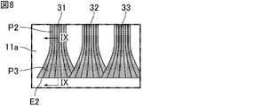
- FIG. 8 is an enlarged view of the portion shown by VIII in FIG. 2.
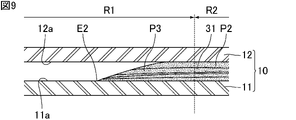
- FIG. 9 is a cross-sectional view taken along the line IX-IX of the wick shown in FIG.
- the second end E2 of the wick 30 such as the wick 31 is the first region of the housing 10. It is located in a third region R3, which is different from R1 (see FIG. 6) and the second region R2.
- the wick 30 such as the wick 31 preferably has a third portion P3 in the third region R3 that is in contact with the first inner wall surface 11a and not in contact with the second inner wall surface 12a.
- the wick 30 such as the wick 31 may have a third portion P3 in the third region R3 that is in contact with the second inner wall surface 12a and not in contact with the first inner wall surface 11a.
- the wick 30 such as the wick 31 does not have to have the third portion P3 in the third region R3.
- At least one wick 30 may have a third portion P3, but it is preferable that all wicks 30 have a third portion P3.
- the third region R3 is preferably located in the condensed portion CP.
- the third portion P3 is thinner than the second portion P2.
- the thinned third portion P3 increases the exposed surface of the fibers between the first inner wall surface 11a and the second inner wall surface 12a, so that the condensed working medium 20 can be easily collected.
- the wick 30 such as the wick 31 may have the third portion P3 somewhere in the third region R3, but the third portion P3 of the wick 30 is the second portion of the wick 30 as shown in FIG. It is preferable to include the end E2.
- the third portion P3 of the wick 30 such as the wick 31 is thicker than the second portion P2 of the wick 30 in a plan view of the first inner wall surface 11a from the thickness direction Z.
- the third portion P3 of one wick 30 and the third portion P3 of the other wick 30 may be connected.
- the third portion P3 of one wick 30 and the third portion P3 of the other wick 30 may be separated from each other among the adjacent wicks 30.
- the width of the wick 30 such as the wick 31 is preferably 500 ⁇ m or more and 5000 ⁇ m or less in the second portion P2, respectively.
- the widths of the wicks 30 in the second portion P2 may be the same or different.
- the width of the wick 30 may or may not be constant in the thickness direction Z. Further, the wick 30 having a constant width in the thickness direction Z and the wick 30 having a non-constant width in the thickness direction Z may coexist.
- the height of the wick 30 such as the wick 31 is preferably 20 ⁇ m or more and 300 ⁇ m or less, and more preferably 50 ⁇ m or more and 200 ⁇ m or less in the second portion P2, respectively.
- the heights of the wicks 30 in the second portion P2 may be the same or different.
- the planar shape of the housing when viewed from the thickness direction is different from that of the first embodiment.
- FIG. 10 is a plan view schematically showing an example of a vapor chamber according to a second embodiment of the present invention.
- the vapor chamber 2 shown in FIG. 10 includes a housing 10A, a working medium 20, and a plurality of wicks 30.
- the planar shape of the housing 10A is L-shaped.
- the planar shape of the housing 10A may be, for example, a staircase type.
- the plurality of wicks 30 include, for example, six wicks 31, 32, 33, 34, 35 and 36.
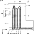
- FIG. 11 is a plan view schematically showing another example of the vapor chamber according to the second embodiment of the present invention.
- the vapor chamber 2A shown in FIG. 11 includes a housing 10A, a working medium 20, and a plurality of wicks 30A.
- the planar shape of the housing 10A is L-shaped, as in FIG. 10.
- the plurality of wicks 30A include, for example, six wicks 31, 32, 33, 34, 35 and 36A.
- the wick 36A extends to the wall surface of the housing 10A located below the evaporation portion EP, and then further extends along the wall surface.
- the wick 30 or 30A such as the wick 31 preferably extends linearly regardless of the planar shape of the housing 10A, and may extend along the planar shape of the housing 10A. More preferred. Thereby, for example, the working medium 20 can be circulated from the evaporation unit EP to the condensation unit CP at a short distance.
- the planar shape of the housing when viewed from the thickness direction is not particularly limited, and examples thereof include polygons such as triangles and rectangles, circles, ellipses, and combinations thereof. Further, the planar shape of the housing may be L-shaped, C-shaped (U-shaped), staircase-shaped, or the like. Further, a through hole may be provided inside the housing.
- the planar shape of the housing may be a shape corresponding to the application of the heat diffusion device, the shape of the place where the heat diffusion device is incorporated, and other components existing in the vicinity.
- the wick is arranged in the entire internal space of the housing.
- FIG. 12 is a plan view schematically showing an example of the vapor chamber according to the third embodiment of the present invention.
- the vapor chamber 3 shown in FIG. 12 includes a housing 10, a working medium 20, and a plurality of wicks 30B.
- the plurality of wicks 30B include, for example, five wicks 31, 32, 33, 34 and 37.
- the wicks 31, 32, 33 and 34 each extend below the evaporation section EP.
- the wick 37 extends along the outer peripheral portion of the internal space of the housing 10.
- the wick 30B is preferably arranged so as to be concentrated in the evaporation unit EP.
- the wicks 31, 32, 33 and 34 are preferably arranged so that the first end E1 is concentrated in the evaporation unit EP, and the wick 37 has the first end E1 and the second end E2 evaporated. It is preferable that they are arranged so as to be aggregated in the part EP.
- the first steam flow path 51 is formed between the adjacent wicks 30B.
- the wick is arranged only in the outer peripheral portion of the internal space of the housing.
- FIG. 13 is a plan view schematically showing an example of the vapor chamber according to the fourth embodiment of the present invention.
- the vapor chamber 4 shown in FIG. 13 includes a housing 10, a working medium 20, and one wick 30C.
- the wick 30C is arranged only in the outer peripheral portion of the internal space of the housing 10.
- the wick 30C extends along the outer peripheral portion of the internal space of the housing 10. As shown in FIG. 13, the wick 30C is preferably arranged so that the first end E1 and the second end E2 are concentrated in the evaporation unit EP.
- the steam flow path 50 is formed in the space surrounded by the wick 30C.
- the heat diffusion device of the present invention is not limited to the above embodiment, and various applications and modifications can be added within the scope of the present invention regarding the configuration of the heat diffusion device, manufacturing conditions, and the like.
- a plurality of wicks may be arranged between the first inner wall surface and the second inner wall surface of the housing.
- the plurality of wicks extend from the first end to the second end so as to be parallel to each other in a plan view from the thickness direction of the first inner wall surface.
- one wick may be arranged between the first inner wall surface and the second inner wall surface of the housing. In that case, the wick extends from the first end to the second end in a plan view from the thickness direction of the first inner wall surface.
- the first sheet and the second sheet may be overlapped so that the ends coincide with each other, or the ends may be overlapped with each other. May be offset and overlap.
- the material constituting the first sheet and the material constituting the second sheet may be different.
- the stress applied to the housing can be dispersed.
- different materials for both one sheet can obtain one function and the other sheet can obtain another function.
- the above-mentioned functions are not particularly limited, and examples thereof include a heat conduction function and an electromagnetic wave shielding function.
- the width of the wick in the cross section perpendicular to the direction in which the wick extends, may be constant in the thickness direction or may not be constant in the thickness direction.
- the wick in a cross section perpendicular to the direction in which the wick extends, may have a width of the end portion on the second inner wall surface side narrower than the width of the end portion on the first inner wall surface side, and the wick may be narrower than the width of the end portion on the second inner wall surface side.
- the width of the end portion on the first inner wall surface side may be narrower than the width of the portion.
- a portion having a constant width may be included.
- the housing may have a plurality of evaporation parts.
- a plurality of columns that support the first inner wall surface and the second inner wall surface of the housing from the inside may be arranged in the steam flow path.
- the steam flow path is divided between the columns.
- the columns support the first inner wall surface and the second inner wall surface of the housing from the inside.
- the number of wicks is small, it is possible to support the housing by arranging columns in the steam flow path.
- the columns are arranged in all the steam flow paths, but there may be a steam flow path in which the columns are not arranged.
- the strut may be in contact with both the first inner wall surface and the second inner wall surface, or may be in contact with either the first inner wall surface or the second inner wall surface, and the first inner wall surface and the second inner wall surface may be in contact with each other. It is not necessary to touch both of them.
- the material forming the column is not particularly limited, and examples thereof include resin, metal, ceramics, a mixture thereof, and a laminate.
- the support column may be integrated with the housing, and may be formed by, for example, etching the inner wall surface of the first sheet or the second sheet.
- the shape of the strut is not particularly limited as long as it can support the housing, but examples of the shape of the cross section perpendicular to the height direction of the strut include polygons such as rectangles, circles, and ellipses.
- the height of the columns is not particularly limited and may be the same as or different from the height of the wick.
- the height of the columns may be the same or different in one heat diffusion device.
- the height of the stanchions in one area may be different from the height of the stanchions in another area.
- the width of the strut is not particularly limited as long as it gives strength that can suppress the deformation of the housing of the heat diffusion device, but the equivalent circle diameter of the cross section perpendicular to the height direction of the end of the strut is, for example, 100 ⁇ m or more and 2000 ⁇ m. It is less than or equal to, preferably 300 ⁇ m or more and 1000 ⁇ m or less.
- the equivalent circle diameter of the column By increasing the equivalent circle diameter of the column, deformation of the housing of the heat diffusion device can be further suppressed.
- by reducing the diameter equivalent to the circle of the column it is possible to secure a wider space for the steam of the working medium to move.
- the arrangement of the columns is not particularly limited, but is preferably arranged evenly in a predetermined area, more preferably evenly over the entire area, for example, so that the distance between the columns is constant. By arranging the columns evenly, uniform strength can be ensured throughout the heat diffusion device.
- the heat diffusion device of the present invention may further include a wick other than the wick described above.
- the heat diffusion device of the present invention may further include at least one of the wicks arranged along the first inner wall surface and the wicks arranged along the second inner wall surface.
- the wick arranged along the first inner wall surface and the wick arranged along the second inner wall surface are not particularly limited as long as they have a capillary structure capable of moving the working medium by a capillary force.
- the capillary structure of the wick may be a known structure used in conventional heat diffusion devices. Examples of the capillary structure include microstructures having irregularities such as pores, grooves, and protrusions, such as a porous structure, a fiber structure, a groove structure, and a mesh structure.
- the material of the wick arranged along the first inner wall surface and the material of the wick arranged along the second inner wall surface are not particularly limited, and for example, a metal porous film formed by etching or metal processing, a mesh, a non-woven fabric, and the like.
- a sintered body, a porous body, or the like is used.
- the mesh used as the material of the wick may be composed of, for example, a metal mesh, a resin mesh, or a surface-coated mesh thereof, and is preferably composed of a copper mesh, a stainless (SUS) mesh, or a polyester mesh. ..
- the sintered body used as the material of the wick may be composed of, for example, a metal porous sintered body or a ceramic porous sintered body, and is preferably composed of a copper or nickel porous sintered body. ..
- the porous body used as the material of the wick may be, for example, a porous body made of a metal porous body, a ceramic porous body, a resin porous body, or the like.
- the size and shape of the wick arranged along the first inner wall surface and the wick arranged along the second inner wall surface are not particularly limited, but are, for example, continuous from the evaporation part to the condensing part inside the housing. It is preferable to have a size and a shape that can be installed.
- the thickness of the wick arranged along the first inner wall surface and the thickness of the wick arranged along the second inner wall surface are not particularly limited, but are, for example, 2 ⁇ m or more and 200 ⁇ m or less, preferably 5 ⁇ m or more and 100 ⁇ m or less, respectively. More preferably, it is 10 ⁇ m or more and 40 ⁇ m or less.
- the thickness of the wick arranged along the first inner wall surface and the thickness of the wick arranged along the second inner wall surface may be partially different.
- the thickness of the wick arranged along the first inner wall surface may be the same as or different from the thickness of the wick arranged along the second inner wall surface.
- the heat diffusion device of the present invention can be mounted on an electronic device for the purpose of heat dissipation. Therefore, an electronic device provided with the heat diffusion device of the present invention is also one of the present inventions. Examples of the electronic device of the present invention include smartphones, tablet terminals, notebook computers, game devices, wearable devices and the like. As described above, the heat diffusion device of the present invention operates independently without the need for external power, and can diffuse heat two-dimensionally at high speed by utilizing the latent heat of vaporization and the latent heat of condensation of the working medium. Therefore, the electronic device provided with the heat diffusion device of the present invention can effectively dissipate heat in the limited space inside the electronic device.
- the first region of the heat diffusion device of the present invention is preferably a region in which a heat source is arranged.
- an integrated circuit IC
- the total area of the wicks overlapping the integrated circuit is 15% or more of the total area of the integrated circuit in a plan view from the thickness direction of the first inner wall surface.
- the wick that overlaps the integrated circuit with a length of 30% or more with respect to the distance from the center to the end of the integrated circuit and the end from the center of the integrated circuit. It is preferable that there is a wick that overlaps the integrated circuit with a length of 15% or more and less than 30% with respect to the distance to the part.
- the heat diffusion device of the present invention can be used for a wide range of applications in the field of portable information terminals and the like. For example, it can be used to lower the temperature of a heat source such as a CPU and extend the usage time of an electronic device, and can be used for a smartphone, a tablet terminal, a notebook computer, or the like.
- Vapor chamber (heat diffusion device) 10 10A Housing 11 1st sheet 11a 1st inner wall surface 12 2nd sheet 12a 2nd inner wall surface 20 Working medium 30, 30A, 30B, 30C, 31, 32, 33, 34, 35, 36, 36A, 37 Wick 50 Steam flow path 51 1st steam flow path 52 2nd steam flow path 53 3rd steam flow path F Fiber E1 1st end E2 2nd end P1 1st part P2 2nd part P3 3rd part R1 1st area R2 1st 2 regions R3 3rd region CP Condensation part EP Evaporation part HS Heat source X Width direction Y Length direction Z Thickness direction
Landscapes
- Engineering & Computer Science (AREA)
- Life Sciences & Earth Sciences (AREA)
- Sustainable Development (AREA)
- Physics & Mathematics (AREA)
- Thermal Sciences (AREA)
- Mechanical Engineering (AREA)
- General Engineering & Computer Science (AREA)
- Cooling Or The Like Of Semiconductors Or Solid State Devices (AREA)
- Cooling Or The Like Of Electrical Apparatus (AREA)
- Vaporization, Distillation, Condensation, Sublimation, And Cold Traps (AREA)
Priority Applications (2)
| Application Number | Priority Date | Filing Date | Title |
|---|---|---|---|
| JP2022559624A JP7283641B2 (ja) | 2020-11-04 | 2021-10-07 | 熱拡散デバイス |
| CN202190000554.5U CN220187502U (zh) | 2020-11-04 | 2021-10-07 | 热扩散器件以及电子设备 |
Applications Claiming Priority (2)
| Application Number | Priority Date | Filing Date | Title |
|---|---|---|---|
| JP2020184381 | 2020-11-04 | ||
| JP2020-184381 | 2020-11-04 |
Publications (1)
| Publication Number | Publication Date |
|---|---|
| WO2022097417A1 true WO2022097417A1 (ja) | 2022-05-12 |
Family
ID=81457130
Family Applications (1)
| Application Number | Title | Priority Date | Filing Date |
|---|---|---|---|
| PCT/JP2021/037140 Ceased WO2022097417A1 (ja) | 2020-11-04 | 2021-10-07 | 熱拡散デバイス |
Country Status (4)
| Country | Link |
|---|---|
| JP (1) | JP7283641B2 (https=) |
| CN (1) | CN220187502U (https=) |
| TW (1) | TWI790794B (https=) |
| WO (1) | WO2022097417A1 (https=) |
Families Citing this family (1)
| Publication number | Priority date | Publication date | Assignee | Title |
|---|---|---|---|---|
| JP7834141B2 (ja) * | 2024-08-02 | 2026-03-23 | 東芝ホームテクノ株式会社 | シート状ヒートパイプ |
Citations (3)
| Publication number | Priority date | Publication date | Assignee | Title |
|---|---|---|---|---|
| US20070251673A1 (en) * | 2006-04-28 | 2007-11-01 | Foxconn Technology Co., Ltd. | Heat pipe with non-metallic type wick structure |
| US20150101783A1 (en) * | 2013-10-15 | 2015-04-16 | Hao Pai | Thermal conductor with ultra-thin flat wick structure |
| JP2015121373A (ja) * | 2013-12-24 | 2015-07-02 | 古河電気工業株式会社 | ヒートパイプ |
Family Cites Families (4)
| Publication number | Priority date | Publication date | Assignee | Title |
|---|---|---|---|---|
| US20160131437A1 (en) | 2014-11-12 | 2016-05-12 | Asia Vital Components Co., Ltd. | Thin heat pipe structure |
| TWI794886B (zh) * | 2017-02-24 | 2023-03-01 | 日商大日本印刷股份有限公司 | 蒸氣腔、電子機器及蒸氣腔之製造方法 |
| TW201924512A (zh) * | 2017-11-06 | 2019-06-16 | 日商大日本印刷股份有限公司 | 蒸氣腔、電子機器、蒸氣腔用片材以及蒸氣腔用片材及蒸氣腔之製造方法 |
| JP6888751B2 (ja) * | 2019-03-11 | 2021-06-16 | 大日本印刷株式会社 | ベーパーチャンバ、電子機器、及び、ベーパーチャンバ用シート |
-
2021
- 2021-10-07 WO PCT/JP2021/037140 patent/WO2022097417A1/ja not_active Ceased
- 2021-10-07 JP JP2022559624A patent/JP7283641B2/ja active Active
- 2021-10-07 CN CN202190000554.5U patent/CN220187502U/zh active Active
- 2021-10-28 TW TW110140108A patent/TWI790794B/zh active
Patent Citations (3)
| Publication number | Priority date | Publication date | Assignee | Title |
|---|---|---|---|---|
| US20070251673A1 (en) * | 2006-04-28 | 2007-11-01 | Foxconn Technology Co., Ltd. | Heat pipe with non-metallic type wick structure |
| US20150101783A1 (en) * | 2013-10-15 | 2015-04-16 | Hao Pai | Thermal conductor with ultra-thin flat wick structure |
| JP2015121373A (ja) * | 2013-12-24 | 2015-07-02 | 古河電気工業株式会社 | ヒートパイプ |
Also Published As
| Publication number | Publication date |
|---|---|
| TWI790794B (zh) | 2023-01-21 |
| TW202225628A (zh) | 2022-07-01 |
| JPWO2022097417A1 (https=) | 2022-05-12 |
| JP7283641B2 (ja) | 2023-05-30 |
| CN220187502U (zh) | 2023-12-15 |
Similar Documents
| Publication | Publication Date | Title |
|---|---|---|
| JP7111266B2 (ja) | ベーパーチャンバー | |
| TW201825850A (zh) | 熱管 | |
| WO2022097417A1 (ja) | 熱拡散デバイス | |
| CN222638937U (zh) | 热扩散器件以及电子设备 | |
| JP7260062B2 (ja) | 熱拡散デバイス | |
| WO2023238626A1 (ja) | 熱拡散デバイス及び電子機器 | |
| JP7311057B2 (ja) | 熱拡散デバイスおよび電子機器 | |
| WO2023171408A1 (ja) | 熱拡散デバイス及び電子機器 | |
| WO2023238625A1 (ja) | 熱拡散デバイス及び電子機器 | |
| WO2023182029A1 (ja) | 熱拡散デバイス及び電子機器 | |
| CN223649761U (zh) | 热扩散装置和电子设备 | |
| CN223023264U (zh) | 热扩散器件以及电子设备 | |
| CN220853247U (zh) | 热扩散器件以及电子设备 | |
| WO2022230357A1 (ja) | 熱拡散デバイス | |
| JP7120494B1 (ja) | 熱拡散デバイス | |
| WO2022230296A1 (ja) | 熱拡散デバイス | |
| CN222733421U (zh) | 热扩散器件和电子设备 | |
| TWI839928B (zh) | 熱擴散器件及電子機器 | |
| CN220750894U (zh) | 电子设备以及热扩散器件 | |
| JP7222448B2 (ja) | 熱拡散デバイス | |
| WO2024142975A1 (ja) | 熱拡散デバイス及び電子機器 | |
| WO2022230295A1 (ja) | 熱拡散デバイス | |
| WO2023026896A1 (ja) | 熱拡散デバイス | |
| WO2023058595A1 (ja) | 熱拡散デバイス | |
| WO2023286577A1 (ja) | 熱拡散デバイス及び電子機器 |
Legal Events
| Date | Code | Title | Description |
|---|---|---|---|
| 121 | Ep: the epo has been informed by wipo that ep was designated in this application |
Ref document number: 21888970 Country of ref document: EP Kind code of ref document: A1 |
|
| ENP | Entry into the national phase |
Ref document number: 2022559624 Country of ref document: JP Kind code of ref document: A |
|
| WWE | Wipo information: entry into national phase |
Ref document number: 202190000554.5 Country of ref document: CN |
|
| NENP | Non-entry into the national phase |
Ref country code: DE |
|
| 122 | Ep: pct application non-entry in european phase |
Ref document number: 21888970 Country of ref document: EP Kind code of ref document: A1 |