WO2022097399A1 - Codeur - Google Patents
Codeur Download PDFInfo
- Publication number
- WO2022097399A1 WO2022097399A1 PCT/JP2021/036540 JP2021036540W WO2022097399A1 WO 2022097399 A1 WO2022097399 A1 WO 2022097399A1 JP 2021036540 W JP2021036540 W JP 2021036540W WO 2022097399 A1 WO2022097399 A1 WO 2022097399A1
- Authority
- WO
- WIPO (PCT)
- Prior art keywords
- light
- encoder
- reflection
- light receiving
- structures
- Prior art date
Links
- 239000000758 substrate Substances 0.000 claims description 10
- 230000035945 sensitivity Effects 0.000 abstract description 21
- 239000010410 layer Substances 0.000 description 46
- 238000012986 modification Methods 0.000 description 32
- 230000004048 modification Effects 0.000 description 32
- 239000010408 film Substances 0.000 description 30
- 239000000463 material Substances 0.000 description 16
- 239000011347 resin Substances 0.000 description 16
- 229920005989 resin Polymers 0.000 description 16
- 238000001514 detection method Methods 0.000 description 14
- 230000000052 comparative effect Effects 0.000 description 12
- 239000002184 metal Substances 0.000 description 9
- 238000010586 diagram Methods 0.000 description 6
- 238000006073 displacement reaction Methods 0.000 description 5
- 238000000034 method Methods 0.000 description 5
- 230000003287 optical effect Effects 0.000 description 4
- 230000000694 effects Effects 0.000 description 3
- 230000001678 irradiating effect Effects 0.000 description 3
- 239000007769 metal material Substances 0.000 description 3
- 239000000956 alloy Substances 0.000 description 2
- 229910045601 alloy Inorganic materials 0.000 description 2
- 239000011521 glass Substances 0.000 description 2
- 230000031700 light absorption Effects 0.000 description 2
- 238000004519 manufacturing process Methods 0.000 description 2
- 239000002356 single layer Substances 0.000 description 2
- 238000004544 sputter deposition Methods 0.000 description 2
- 238000007740 vapor deposition Methods 0.000 description 2
- RNFJDJUURJAICM-UHFFFAOYSA-N 2,2,4,4,6,6-hexaphenoxy-1,3,5-triaza-2$l^{5},4$l^{5},6$l^{5}-triphosphacyclohexa-1,3,5-triene Chemical compound N=1P(OC=2C=CC=CC=2)(OC=2C=CC=CC=2)=NP(OC=2C=CC=CC=2)(OC=2C=CC=CC=2)=NP=1(OC=1C=CC=CC=1)OC1=CC=CC=C1 RNFJDJUURJAICM-UHFFFAOYSA-N 0.000 description 1
- 239000006096 absorbing agent Substances 0.000 description 1
- 230000005540 biological transmission Effects 0.000 description 1
- 239000000919 ceramic Substances 0.000 description 1
- 238000000576 coating method Methods 0.000 description 1
- 238000005516 engineering process Methods 0.000 description 1
- 239000003063 flame retardant Substances 0.000 description 1
- 238000010248 power generation Methods 0.000 description 1
- 230000001360 synchronised effect Effects 0.000 description 1
- 239000010409 thin film Substances 0.000 description 1
- 239000012780 transparent material Substances 0.000 description 1
Images


Classifications
-
- G—PHYSICS
- G01—MEASURING; TESTING
- G01D—MEASURING NOT SPECIALLY ADAPTED FOR A SPECIFIC VARIABLE; ARRANGEMENTS FOR MEASURING TWO OR MORE VARIABLES NOT COVERED IN A SINGLE OTHER SUBCLASS; TARIFF METERING APPARATUS; MEASURING OR TESTING NOT OTHERWISE PROVIDED FOR
- G01D5/00—Mechanical means for transferring the output of a sensing member; Means for converting the output of a sensing member to another variable where the form or nature of the sensing member does not constrain the means for converting; Transducers not specially adapted for a specific variable
- G01D5/26—Mechanical means for transferring the output of a sensing member; Means for converting the output of a sensing member to another variable where the form or nature of the sensing member does not constrain the means for converting; Transducers not specially adapted for a specific variable characterised by optical transfer means, i.e. using infrared, visible, or ultraviolet light
- G01D5/32—Mechanical means for transferring the output of a sensing member; Means for converting the output of a sensing member to another variable where the form or nature of the sensing member does not constrain the means for converting; Transducers not specially adapted for a specific variable characterised by optical transfer means, i.e. using infrared, visible, or ultraviolet light with attenuation or whole or partial obturation of beams of light
- G01D5/34—Mechanical means for transferring the output of a sensing member; Means for converting the output of a sensing member to another variable where the form or nature of the sensing member does not constrain the means for converting; Transducers not specially adapted for a specific variable characterised by optical transfer means, i.e. using infrared, visible, or ultraviolet light with attenuation or whole or partial obturation of beams of light the beams of light being detected by photocells
- G01D5/347—Mechanical means for transferring the output of a sensing member; Means for converting the output of a sensing member to another variable where the form or nature of the sensing member does not constrain the means for converting; Transducers not specially adapted for a specific variable characterised by optical transfer means, i.e. using infrared, visible, or ultraviolet light with attenuation or whole or partial obturation of beams of light the beams of light being detected by photocells using displacement encoding scales
- G01D5/34707—Scales; Discs, e.g. fixation, fabrication, compensation
-
- G—PHYSICS
- G01—MEASURING; TESTING
- G01D—MEASURING NOT SPECIALLY ADAPTED FOR A SPECIFIC VARIABLE; ARRANGEMENTS FOR MEASURING TWO OR MORE VARIABLES NOT COVERED IN A SINGLE OTHER SUBCLASS; TARIFF METERING APPARATUS; MEASURING OR TESTING NOT OTHERWISE PROVIDED FOR
- G01D5/00—Mechanical means for transferring the output of a sensing member; Means for converting the output of a sensing member to another variable where the form or nature of the sensing member does not constrain the means for converting; Transducers not specially adapted for a specific variable
- G01D5/26—Mechanical means for transferring the output of a sensing member; Means for converting the output of a sensing member to another variable where the form or nature of the sensing member does not constrain the means for converting; Transducers not specially adapted for a specific variable characterised by optical transfer means, i.e. using infrared, visible, or ultraviolet light
- G01D5/32—Mechanical means for transferring the output of a sensing member; Means for converting the output of a sensing member to another variable where the form or nature of the sensing member does not constrain the means for converting; Transducers not specially adapted for a specific variable characterised by optical transfer means, i.e. using infrared, visible, or ultraviolet light with attenuation or whole or partial obturation of beams of light
- G01D5/34—Mechanical means for transferring the output of a sensing member; Means for converting the output of a sensing member to another variable where the form or nature of the sensing member does not constrain the means for converting; Transducers not specially adapted for a specific variable characterised by optical transfer means, i.e. using infrared, visible, or ultraviolet light with attenuation or whole or partial obturation of beams of light the beams of light being detected by photocells
- G01D5/347—Mechanical means for transferring the output of a sensing member; Means for converting the output of a sensing member to another variable where the form or nature of the sensing member does not constrain the means for converting; Transducers not specially adapted for a specific variable characterised by optical transfer means, i.e. using infrared, visible, or ultraviolet light with attenuation or whole or partial obturation of beams of light the beams of light being detected by photocells using displacement encoding scales
- G01D5/3473—Circular or rotary encoders
-
- G—PHYSICS
- G01—MEASURING; TESTING
- G01D—MEASURING NOT SPECIALLY ADAPTED FOR A SPECIFIC VARIABLE; ARRANGEMENTS FOR MEASURING TWO OR MORE VARIABLES NOT COVERED IN A SINGLE OTHER SUBCLASS; TARIFF METERING APPARATUS; MEASURING OR TESTING NOT OTHERWISE PROVIDED FOR
- G01D5/00—Mechanical means for transferring the output of a sensing member; Means for converting the output of a sensing member to another variable where the form or nature of the sensing member does not constrain the means for converting; Transducers not specially adapted for a specific variable
- G01D5/26—Mechanical means for transferring the output of a sensing member; Means for converting the output of a sensing member to another variable where the form or nature of the sensing member does not constrain the means for converting; Transducers not specially adapted for a specific variable characterised by optical transfer means, i.e. using infrared, visible, or ultraviolet light
- G01D5/32—Mechanical means for transferring the output of a sensing member; Means for converting the output of a sensing member to another variable where the form or nature of the sensing member does not constrain the means for converting; Transducers not specially adapted for a specific variable characterised by optical transfer means, i.e. using infrared, visible, or ultraviolet light with attenuation or whole or partial obturation of beams of light
- G01D5/34—Mechanical means for transferring the output of a sensing member; Means for converting the output of a sensing member to another variable where the form or nature of the sensing member does not constrain the means for converting; Transducers not specially adapted for a specific variable characterised by optical transfer means, i.e. using infrared, visible, or ultraviolet light with attenuation or whole or partial obturation of beams of light the beams of light being detected by photocells
- G01D5/347—Mechanical means for transferring the output of a sensing member; Means for converting the output of a sensing member to another variable where the form or nature of the sensing member does not constrain the means for converting; Transducers not specially adapted for a specific variable characterised by optical transfer means, i.e. using infrared, visible, or ultraviolet light with attenuation or whole or partial obturation of beams of light the beams of light being detected by photocells using displacement encoding scales
- G01D5/34707—Scales; Discs, e.g. fixation, fabrication, compensation
- G01D5/34715—Scale reading or illumination devices
Definitions
- This disclosure relates to an encoder, and particularly to an optical encoder.
- Servo motors built into machine tools, robots, etc. use encoders to detect the rotation angle of the servo motors.
- a mechanical encoder, a magnetic encoder, an optical encoder and the like are known.
- the encoder not only a rotary encoder (rotary encoder) that detects a rotational displacement such as a rotation angle, but also a linear encoder (linear encoder) that detects a linear displacement is known.
- encoders include an absolute type encoder that detects displacement as an absolute value and an incremental type encoder that detects displacement as a relative value.
- a rotary encoder includes an absolute encoder that detects an absolute angle and an incremental encoder that detects a relative angle.
- a light transmission type encoder is known as an absolute type or incremental type optical rotary encoder (for example, Patent Document 1).
- a motor that rotates by irradiating a rotating plate provided with a plurality of light-transmitting portions composed of slits or the like with light in a predetermined pattern and receiving the light transmitted through the light-transmitting portion. Etc. are detected.
- a light reflection type encoder has been studied due to the demand for miniaturization and high position resolution of the encoder.
- a light reflection type rotary encoder one having a rotating plate in which a light reflecting portion (light reflecting region) and a non-light reflecting portion are formed in a predetermined pattern is known.
- the light-reflecting rotary encoder having such a configuration is miniaturized to have high position resolution, for example, in order to obtain twice the position accuracy, a light-reflecting portion and a non-light-reflecting portion formed on a rotating plate are formed. It is conceivable to halve each size (size along the direction of rotation) of.
- the light reflecting portion and the non-light reflecting portion are miniaturized, higher accuracy is required for the position or shape of the light reflecting portion and the non-light reflecting portion. Therefore, there is a limit to miniaturizing the light reflecting portion and the non-light reflecting portion. Moreover, in order to accurately form the miniaturized light reflecting portion, advanced manufacturing technology may be required.
- the present disclosure has been made to solve such a problem, and to provide an encoder capable of achieving high position resolution without miniaturization and detecting the rotation angle and the like with high sensitivity. With the goal.
- one aspect of the encoder includes a substrate, an irradiation unit, and a light receiving unit.
- the substrate rotates or moves linearly.
- the substrate has a plurality of repeatedly formed reflective structures and a cord including a light reflecting portion or a light transmitting portion.
- the irradiation unit irradiates a plurality of reflection structures with light.
- the light receiving unit receives light reflected by a plurality of reflection structures.
- Each of the plurality of reflective structures has a convex or concave surface.
- the width of each of the plurality of reflective structures is an integral multiple of the width of the light reflecting portion or the light transmitting portion.
- the encoder according to the present disclosure can achieve high position resolution without miniaturization, and can detect the angle of rotation and the like with high sensitivity.
- FIG. 3 is a partially enlarged cross-sectional view of an encoder cut along a plane perpendicular to the paper surface through the line IIIA-IIIA of FIG.
- FIG. 3 is a partially enlarged cross-sectional view of an encoder cut along a plane perpendicular to the paper surface through the line IIIB-IIIB of FIG.
- FIG. It is a figure for demonstrating the operation of the light reflection type encoder of the 1st comparative example.
- FIG. It is a figure for demonstrating the operation of the light reflection type encoder of the 2nd comparative example. It is a figure for demonstrating operation of the encoder which concerns on Embodiment 1.
- FIG. It is a partially enlarged sectional view of the encoder which concerns on the 1st modification of Embodiment 1.
- FIG. It is a partially enlarged sectional view of the encoder which concerns on the 1st modification of Embodiment 1.
- FIG. It is a figure for demonstrating operation of the encoder which concerns on the 1st modification of Embodiment 1.
- FIG. It is an enlarged figure which shows the irradiation part and one reflection structure in the encoder which concerns on the 1st modification of Embodiment 1.
- FIG. It is an enlarged figure which shows the irradiation part and one reflection structure in the encoder which concerns on the 2nd modification of Embodiment 1.
- FIG. It is a partially enlarged sectional view of the encoder which concerns on Embodiment 2.
- FIG. It is a partially enlarged sectional view of the encoder which concerns on Embodiment 2.
- FIG. It is a partially enlarged sectional view of the encoder which concerns on the modification of Embodiment 2.
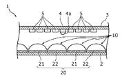
- FIG. 1 is a top view of the rotary plate 2 in the encoder 1 according to the first embodiment.
- FIG. 2 is a cross-sectional view of the encoder 1 taken along the line II-II of FIG. 1 and cut along a plane perpendicular to the paper surface.
- FIG. 3A is a partially enlarged view of the encoder 1 cut along the line IIIA-IIIA of FIG. 1 along a plane perpendicular to the paper surface.
- FIG. 3B is a partially enlarged view of the encoder 1 cut along the line IIIB-IIIB of FIG. 1 on a plane perpendicular to the paper surface.
- the non-light reflecting portion 22 is hatched for convenience.
- the encoder 1 shown in FIGS. 1 and 2 is an optical rotary encoder.
- the encoder 1 in the present embodiment is a reflection type rotary encoder.
- the encoder 1 is used in combination with a motor such as a servo motor, for example. In this case, the encoder 1 detects, for example, the rotation angle or the rotation speed of the rotation shaft of the motor.
- the encoder 1 includes a rotating plate 2, a fixing unit 3, an irradiation unit 4, a light receiving unit 5, and a processing unit 6.
- the rotating plate 2 is a rotating substrate.
- the rotation direction of the rotary plate 2 is both clockwise and counterclockwise, but is not limited to this.
- the rotation direction of the rotating plate 2 may be only one of clockwise and counterclockwise.
- the rotary plate 2 is made of metal, for example, but may be made of resin, glass, ceramic, or the like. Further, the rotating plate 2 has a circular flat plate shape as an example.
- a rotating shaft 7 is attached to the central portion of the rotating plate 2. By rotating the rotating shaft 7, the rotating plate 2 rotates with the rotating shaft 7 as the center of rotation. The rotational operation of the rotating shaft 7 is synchronized with the rotational operation of the rotating device.
- the rotary shaft 7 is the rotary shaft itself of a motor such as a servo motor.
- the rotating plate 2 has a plurality of reflective structures 10 repeatedly formed.
- the plurality of reflection structures 10 are light reflectors that reflect the light emitted from the irradiation unit 4, and are formed in a predetermined first pattern.
- the plurality of reflective structures 10 are provided in a row along the circumferential direction of the rotating plate 2. As shown in FIG. 2, the plurality of reflective structures 10 are provided on the main surface of the rotating plate 2 facing the fixed portion 3.
- a plurality of reflection structures 10 are provided over the entire circumference of the rotating plate 2. Further, the plurality of reflective structures 10 are formed at the radialmost ends of the rotating plate 2. Therefore, the plurality of reflection structures 10 are formed on the outermost track of the rotating plate 2.
- Each of the plurality of reflective structures 10 has the same shape and the same size. Further, in all of the plurality of reflection structures 10, the intervals between the two adjacent reflection structures 10 are all the same. That is, the plurality of reflective structures 10 are formed at equal intervals (same pitch) on the entire circumference of the rotating plate 2.
- each of the plurality of reflective structures 10 has a convex surface.
- the cross-sectional shape of each reflection structure 10 is semi-circular.
- each reflection structure 10 is a semicircular column whose axis is the radial direction of the rotating plate 2. Therefore, the surface (light reflecting surface) of each reflecting structure 10 is a cylindrical surface that is convex upward.
- the plurality of reflective structures 10 have a shape in which irregularities are repeated along the circumferential direction of the rotating plate 2 as a whole.
- the surface of each reflective structure 10 may be a hemispherical spherical surface instead of a cylindrical surface, but in order to accurately detect the reflected light from the reflective structure 10, it is preferable that the surface is a cylindrical surface.
- each of the plurality of reflective structures 10 has a convex portion 11 and a light reflecting layer 12 formed on the convex portion 11.
- the light reflecting layer 12 is formed on the surface of the convex portion 11 and is the uppermost layer of the reflecting structure 10. Therefore, the surface of each reflection structure 10 is the surface of the light reflection layer 12.
- the convex portion 11 is a semicircular column whose axis is the radial direction of the rotating plate 2.
- the convex portion 11 is made of, for example, a resin material.
- the convex portion 11 may be either a light transmitting resin material such as a transparent resin material or an opaque resin material.
- the convex portion 11 can be manufactured by the same method as that of the microlens array.
- the material of the convex portion 11 is not limited to the resin material, and may be made of a metal material or the like.
- the light reflecting layer 12 is, for example, a light reflecting film having a light reflecting characteristic having a high reflectance with respect to the light emitted from the irradiation unit 4.
- the surface (light-reflecting surface) of the light-reflecting layer 12 is a cylindrical surface that is convex upward.
- the light reflecting layer 12 can be formed by sputtering, vapor deposition, or the like.
- the light reflecting layer 12 is a metal film made of a metal material. In this case, the metal film may be composed of a single metal or an alloy.
- the light reflecting layer 12 is a light reflecting film having a constant thickness.
- the light reflecting layer 12 is a single-layer film composed of one light reflecting film, but is not limited to this.
- the light reflecting layer 12 may be a laminated film in which a plurality of light reflecting films are laminated. Further, the light reflecting layer 12 is not limited to the metal film.
- the light reflecting layer 12 may be a resin film made of a resin material, an oxide film, or the like.
- the light reflecting layer 12 is, for example, a white resin film made of white resin. In this case, the white resin film can be formed by a coating method.
- the light reflecting layer 12 is an oxide film
- the light reflecting layer 12 is, for example, a dielectric multilayer film.
- the plurality of reflective structures 10 are integrally formed.
- the plurality of convex portions 11 are all integrally formed, and are one concave-convex structure in which unevenness is repeated along the circumferential direction of the rotating plate 2.
- the plurality of light reflecting layers 12 are all integrally formed as one continuous light reflecting film having a constant thickness on the uneven structure composed of the plurality of reflecting structures 10.
- the rotating plate 2 has a cord 20 including one or more light reflecting portions 21.
- the code 20 is a position detection code for detecting the rotation position of the rotating plate 2.
- the code 20 is an M code (M-sequence code) having a predetermined number of bits.
- the code 20 is not limited to the M code, but may be a Gray code, a binary code, a BCD (Binary-Coded Decimal) code, or the like.
- the light reflecting unit 21 in the code 20 is a light reflecting body that reflects the light emitted from the irradiation unit 4.
- the code 20 further has a non-light reflecting unit 22 that does not reflect the light emitted from the irradiation unit 4.
- the non-light reflecting unit 22 is, for example, a light absorber that absorbs light.
- the code 20 is composed of a plurality of light reflecting units 21 and a plurality of non-light reflecting units 22. Specifically, the code 20 is composed of five light reflecting units 21 and six non-light reflecting units 22.
- the cord 20 is provided on the main surface of the rotating plate 2 facing the fixed portion 3 in a predetermined second pattern. Specifically, the light reflecting portion 21 and the non-light reflecting portion 22 constituting the cord 20 are provided on the main surface of the rotating plate 2 on the fixed portion 3 side in a predetermined order and in a predetermined number.
- the cord 20 is provided along the circumferential direction of the rotating plate 2.
- the plurality of light reflecting portions 21 and the plurality of non-light reflecting portions 22 constituting the cord 20 are provided in a row along the circumferential direction of the rotating plate 2.
- Each of the light reflecting unit 21 and the non-light reflecting unit 22 is a unit code pattern (single region) of the code 20, and is the minimum unit for the light receiving unit 5 to read when detecting the position of the rotating plate 2.
- the cord 20 is provided in a part of the area of the rotating plate 2.
- the code 20 is provided side by side with the plurality of reflection structures 10. That is, the light reflecting portion 21 and the non-light reflecting portion 22 are provided side by side with the plurality of reflecting structures 10.
- the cord 20 is provided inside the plurality of reflection structures 10.
- the cord 20 is formed on the second track from the outermost circumference of the rotating plate 2.
- Each of the plurality of light reflecting portions 21 has the same shape and the same size. Further, each of the plurality of non-light reflecting portions 22 has the same shape and the same size. Further, one light reflecting unit 21 and one non-light reflecting unit 22 have the same shape and the same size. Further, in all the light reflecting parts 21 and all the non-light reflecting parts 22 constituting the code 20, the distance between the two adjacent light reflecting parts 21, the distance between the two adjacent non-light reflecting parts 22, and the adjacent parts are adjacent to each other. The distances between the light reflecting portion 21 and the non-light reflecting portion 22 are all the same. That is, the light reflecting portion 21 and the non-light reflecting portion 22 constituting the cord 20 are all formed at equal intervals (same pitch).
- Each of the light reflecting portion 21 and the non-light reflecting portion 22 is composed of, for example, a thin film having a flat surface.
- the thickness of the light reflecting portion 21 and the thickness of the non-light reflecting portion 22 are the same, but are not limited to this.
- the light reflecting unit 21 is, for example, a light reflecting film having high reflectance and light reflecting property, and can be formed by sputtering, vapor deposition, or the like.
- the light reflecting portion 21 is a metal film made of a metal material.
- the metal film may be composed of a single metal or an alloy.
- the light reflecting unit 21 is not limited to a single layer, and may be a laminated film in which a plurality of light reflecting films are laminated. Further, the light reflecting portion 21 is not limited to the metal film, and may be a resin film made of a resin material, an oxide film, or the like, similarly to the light reflecting layer 12 of the reflective structure 10.
- the non-light reflecting unit 22 is, for example, a light absorbing film that absorbs light.
- a light absorbing film for example, a black resin film can be used, but the light absorption film is not limited to this.
- each of the plurality of reflection structures 10 is an integral multiple of the width (width in the column direction) of the light reflecting portion 21 of the code 20.
- each of the plurality of reflection structures 10 and the light reflection unit 21 have a one-to-one correspondence, and the width of each of the plurality of reflection structures 10 is one times the width of the light reflection unit 21.
- one reflective structure 10 arranged in the radial direction of the rotating plate 2 and one light reflecting portion 21 have the same width.
- the "width" is a width in units of an angle along the column direction (direction along the circumference of the rotating plate 2).
- one reflective structure 10 and one non-light reflecting portion 22 arranged in the radial direction of the rotating plate 2 have the same width as each other.
- one reflection structure 10 and one unit code pattern of the code 20 have a one-to-one correspondence
- one reflection structure 10 and the unit code pattern of the code 20 have a one-to-one correspondence. Have the same width.
- the upper limit of the width of each of the plurality of reflection structures 10 is the total number (maximum number) of the unit code patterns of the code 20.
- the upper limit of the width of each of the plurality of reflection structures 10 is the total value of 14 unit code patterns of the code 20. ..
- the rotation angle of the rotating plate 2 and the like can be calculated by using the light reflected by the plurality of reflection structures 10 and the light reflected by the code 20. In this case, it is not necessary to use all the light reflecting units 21 and all the non-light reflecting units 22 constituting the code 20.
- the rotating plate 2 can be used by using a total of seven light reflecting units 21 and a non-light reflecting unit 22 (that is, by using seven unit code patterns). The rotation angle and the like can be calculated.
- the fixing portion 3 is arranged so as to face the rotating plate 2.
- the fixing portion 3 is a member that does not rotate even if the rotating plate 2 rotates.
- the fixing portion 3 is a circular flat plate-shaped substrate.
- the fixing portion 3 is, for example, a wiring board such as FR-4 (Flame Retardant Type 4), and is arranged in parallel with the rotating plate 2 at a position separated from the rotating plate 2 by a predetermined distance.
- the fixing portion 3 may be arranged so that the center of the fixing portion 3 coincides with the axis of the rotating shaft 7.
- the fixing portion 3 is fixed to, for example, an encoder 1 or a case (not shown) constituting a part of the motor.
- the fixed portion 3 is provided with an irradiation unit 4, a light receiving unit 5, and a processing unit 6.
- the irradiation unit 4, the light receiving unit 5, and the processing unit 6 are mounted as electronic components on the fixing unit 3 which is a wiring board.
- the irradiation unit 4 and the light receiving unit 5 are mounted on, for example, a surface of the fixing unit 3 facing the rotating plate 2.
- the irradiation unit 4 and the light receiving unit 5 may be integrated as a light source module.
- the processing unit 6 is mounted on a surface of the fixing unit 3 opposite to the surface facing the rotating plate 2.
- electronic components other than the irradiation unit 4, the light receiving unit 5, and the processing unit 6 may be mounted on the fixing unit 3.
- the irradiation unit 4 is a light source that irradiates light toward the rotating plate 2. Specifically, the irradiation unit 4 irradiates the plurality of reflection structures 10 and the cord 20 with light. In this case, the irradiation unit 4 irradiates a part of the area of the rotating plate 2 with light. Therefore, the light emitted from the irradiation unit 4 irradiates a part of all the reflection structures 10.
- the irradiation unit 4 is composed of, for example, a light emitting element such as an LED (Light Emitting Diode).
- the light emitted from the irradiation unit 4 is visible light such as white light, but the light is not limited to this.
- the light emitted from the irradiation unit 4 may be, for example, infrared light.
- the encoder 1 has a light collecting member 4a that collects the light emitted from the irradiation unit 4 toward each of the plurality of reflection structures 10.
- the light collecting member 4a is a convex lens.
- the light collecting member 4a is provided, for example, on the emission surface of the irradiation unit 4.
- the irradiation unit 4 and the light collecting member 4a may be configured as an integrated light source module. In this way, by using the light collecting member 4a, the light emitted from the irradiation unit 4 can be collected by the light collecting member 4a and irradiated to the reflection structure 10.
- the position of the focal point of the light collecting member 4a is preferably on the light receiving surface of the light receiving unit 5 (light receiving element).
- the light receiving unit 5 receives the light reflected by the plurality of reflection structures 10.
- the light receiving unit 5 is composed of, for example, a light receiving element such as a PD (Photodiode).
- the light receiving unit 5 has a plurality of light receiving elements. That is, the light reflected by the plurality of reflection structures 10 is received by the plurality of light receiving elements.
- the plurality of light receiving elements are arranged in a row and mounted on the fixed portion 3, for example.
- the plurality of light receiving elements may be integrated as a light receiving module.
- the light receiving unit 5 receives the light reflected by the code 20.
- the light receiving unit 5 has a light receiving element (first light receiving element) that receives the light reflected by the reflection structure 10 and a light receiving element (second light receiving element) that receives the light reflected by the code 20. You may.
- the light receiving unit 5 does not have to be composed of a plurality of light receiving elements as long as each of the plurality of reflection structures 10 and the unit code pattern of the code 20 can be individually received.
- the light receiving unit 5 may be configured by an image pickup element or the like having a light receiving surface capable of simultaneously receiving light reflected by a plurality of reflection structures 10.
- the processing unit 6 shown in FIG. 2 is electrically connected to the light receiving unit 5.
- the processing unit 6 calculates information regarding a change in the position of the rotating plate 2 based on the light receiving positions of the plurality of light receiving elements in the light receiving unit 5. For example, the processing unit 6 calculates the rotation angle, rotation speed, rotation position, rotation speed, and the like of the rotation plate 2 as information regarding the change in the position of the rotation plate 2.
- the processing unit 6 is, for example, an IC (integrated circuit) package or the like.
- FIG. 4 is a diagram for explaining the operation of the encoder 1 according to the first embodiment.
- FIG. 4 only a part of the rotating plate 2 is shown.
- eight light receiving elements 5a to 5h are shown as the light receiving unit 5.
- the irradiation unit 4 irradiates the light ⁇ toward the rotating rotating plate 2
- the light ⁇ emitted from the irradiation unit 4 is sequentially reflected by the plurality of reflection structures 10 arranged in the rotation direction and received by the light receiving unit 5.
- the surface of the reflection structure 10a is a convex reflection surface, so that the rotating plate 2 rotates.
- the relative position of the reflection structure 10a with respect to the irradiation unit 4 changes.
- the light ⁇ emitted from the irradiation unit 4 and reaching the reflection structure 10a is reflected at a reflection angle according to the curvature of the reflection surface of the reflection structure 10a, and is sequentially reflected by the eight light receiving elements 5a to 5h of the light receiving unit 5. It will be incident.
- the reflective structure is formed by the rotation of the rotating plate 2 as shown by the black block arrow in FIG. Even if the position of 10a is slightly changed, the position of the light ⁇ that is reflected by the reflection structure 10a and reaches the light receiving portion 5 can be greatly changed as shown by the white block arrow in FIG.
- the change in the position of the reflected light received by the light receiving unit 5 can be changed in the range of several times to 100 times with respect to the change in the position of the reflection structure 10a (rotating plate 2).
- the position of the reflective structure 10a (rotating plate 2) is changed by 10 ⁇ m
- the position of the reflected light received by the light receiving unit 5 can be changed by about 0.49 mm.
- the light ⁇ irradiated from the irradiation unit 4 and reflected by the reflection structure 10 is incident on only one light receiving element of the light receiving unit 5.
- the light ⁇ emitted from the irradiation unit 4 is condensed by the light collecting member 4a, so that the light ⁇ reflected by the reflection structure 10 is applied to only one light receiving element of the light receiving unit 5. It is incident.
- the light ⁇ received by the light receiving unit 5 (light receiving elements 5a to 5h) is input to the processing unit 6 as an electric signal.
- the width of each of the plurality of reflection structures 10 is an integral multiple (1 times in the present embodiment) of the width of the unit code pattern of the code 20.
- the processing unit 6 can calculate the rotation angle and the like of the rotating plate 2 based on the electric signal from the light receiving unit 5.
- FIG. 5 is a diagram for explaining the operation of the light reflection type encoder 1X of the first comparative example.
- FIG. 6 is a diagram for explaining the operation of the light reflection type encoder 1Y of the second comparative example.
- FIG. 7 is a diagram for explaining the operation of the encoder 1 according to the first embodiment.
- the encoder 1X which is a light-reflecting rotary encoder of the first comparative example
- the light-reflecting unit 21X and the non-light-reflecting unit 22X rotate in a predetermined pattern as incrementals for generating an analog position signal. It is formed on the plate 2X.
- the light reflection type encoder 1X of the first comparative example the light ⁇ emitted from the irradiation unit 4X is divided by the plurality of light reflection units 21X and incident on the light receiving unit 5X. Therefore, the light amount (light intensity) of the light ⁇ received by each light receiving element of the light receiving unit 5X is reduced according to the number of divisions of the plurality of light reflecting units 21X. For example, in the case of seven patterns as shown in FIG. 5, the amount of light ⁇ received by each light receiving element of the light receiving unit 5X is 1/7. That is, the detection sensitivity (S / N ratio) such as the angle of rotation is 1/7.
- the light reflection type encoder 1Y of the second comparative example shown in FIG. 6 is used.
- the sizes of the light reflecting portion 21Y and the non-light reflecting portion 22Y formed on the rotating plate 2Y are set to the light reflecting portion 21X and the non-light in the light reflecting type encoder 1X of the first comparative example shown in FIG. It needs to be halved for each size of the reflector 22X.
- the light reflecting unit 21Y is emitted from the irradiation unit 4Y, reflected by the plurality of light reflecting units 21Y, and incident on the light receiving unit 5Y.
- the amount of reflected light is further half that of the light-reflecting type encoder 1X of the first comparative example of FIG.
- the amount of light ⁇ received by each light receiving element of the light receiving unit 5Y is 1/14. That is, the detection sensitivity (S / N ratio) such as the angle of rotation is 1/14.
- the light emitted from the irradiation unit is divided by a plurality of light reflection units and received by the light receiving unit, so that the light reflection unit and the non-light reflection unit are received.
- the finer the size the greater the number of divisions of the light emitted from the irradiation unit.
- the amount of light received by the light receiving unit becomes small, and the detection sensitivity such as the rotation angle may deteriorate or the rotation angle may not be detected.
- the miniaturized light reflection unit 21Y and non-light reflection unit 22Y are used as in the encoder 1Y which is the light reflection type rotary encoder of the second comparative example of FIG. 6, the light reflection unit 21Y and the non-light reflection unit 21Y and non-light reflection unit are used. Higher accuracy is required for the position or shape of the portion 22Y. That is, if the accuracy of the positions or shapes of the light reflecting portion 21Y and the non-light reflecting portion 22Y deteriorates, the detection accuracy of the rotation angle of the rotating plate 2 deteriorates. Moreover, in order to accurately form the miniaturized light reflecting portion 21Y, advanced manufacturing techniques may be required. That is, it is difficult to accurately form the miniaturized light reflecting portion 21Y.
- an encoder 1 having the structures shown in FIGS. 1 to 4 has been obtained.
- a plurality of reflective structures 10 each having a concave surface and a cord 20 including a light reflecting portion 21 are formed on the rotating plate 2.
- the width of each of the plurality of reflection structures 10 is an integral multiple of the width of the light reflection unit 21 (unit code pattern).
- the width of each of the plurality of reflection structures 10 is one times the width of the light reflection unit 21.
- the displacement of the position of one reflection structure 10 due to the rotation of the rotating plate 2 can be converted by the reflection angle due to the convex reflection surface of the reflection structure 10, so that the amount of movement of one reflection structure 10 ( That is, the amount of movement of the rotating plate 2) can be expanded by the amount of the angle of the reflected light of the reflective structure 10.
- the position of the reflection structure 10a is slightly changed by the rotation of the rotating plate 2
- the position where the light ⁇ reflected by the reflection structure 10 reaches the light receiving portion 5 can be greatly changed.
- the relative position of the rotating plate 2 with respect to the fixed portion 3 is detected not by the light receiving amount of the reflected light but by the light receiving position of the reflected light.
- the light receiving unit 5 has a plurality of light receiving elements, and the rotation angle (position movement) of the rotating plate 2 is detected by the position of each light receiving element.
- the light ⁇ emitted from the irradiation unit 4 toward the reflection structure 10 is not divided by the number of unit code patterns of the code 20, and is one light receiving element of the light receiving unit 5. All are incident on. Specifically, the light ⁇ emitted from the irradiation unit 4 is focused on one light receiving element by the light collecting member 4a.
- the light ⁇ emitted from the irradiation unit 4 toward the reflection structure 10 is focused on the reflection curved surface of the reflection structure 10 of the rotating plate 2, so that the light is emitted from the irradiation unit 4.
- the light ⁇ has a structure in which only one incident angle exists with respect to the unit code pattern of the code 20. Further, among the light ⁇ emitted from the irradiation unit 4, the light directly directed to the code 20 is reflected by the code 20 and directed to the light receiving unit 5. Therefore, the total amount of light emitted from the irradiation unit 4 can be received by the light receiving unit 5, and high angular resolution can be obtained, so that a large detection sensitivity (S / N ratio) can be obtained.
- the code 20 has 11 patterns
- high position resolution can be achieved without miniaturization, and the rotation angle and the like can be detected with high sensitivity.
- the plurality of reflection structures 10 are provided over the entire circumference of the rotary plate 2 along the rotation direction of the rotary plate 2, and the code 20 is a plurality of reflection structures 10. They are installed side by side.
- one irradiation unit 4 can irradiate a plurality of reflection structures 10 and cords 20 with light, and the light receiving unit 5 can efficiently receive the reflected light of the plurality of reflection structures 10 and cord 20.
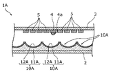
- each of the plurality of reflection structures 10 has a convex surface, but the present invention is not limited to this.
- each of the plurality of reflective structures 10A may have a concave surface.
- 8A and 8B are partially enlarged cross-sectional views of the encoder 1A according to the first modification of the first embodiment. Note that FIGS. 8A and 8B show parts corresponding to FIGS. 3A and 3B showing the configuration of the encoder 1.
- the surface of each of the plurality of reflection structures 10A is a concave light reflection surface.
- the surface of each reflective structure 10A is a downwardly convex cylindrical surface.
- each of the plurality of reflective structures 10A has a recess 11A having a downwardly convex cylindrical surface and a light reflecting layer 12A formed on the surface of the recess 11A.
- Each recess 11A of the plurality of reflective structures 10A is integral, but is not limited to this.
- the light reflecting layer 12A of each of the plurality of reflecting structures 10A is integrated, but the present invention is not limited to this.
- the materials of the concave portion 11A and the light reflecting layer 12A are the same as those of the convex portion 11 and the light reflecting layer 12 of the reflection structure 10 in the encoder 1.
- the width (width in the column direction) of each of the plurality of reflection structures 10A is the light reflecting portion of the code 20 as in the encoder 1 shown in FIG. It is an integral multiple of the width of 21 (width in the column direction).
- one reflective structure 10A arranged in the radial direction of the rotating plate 2, one light reflecting portion 21, and one non-light reflecting portion 22 each have the same width.
- FIG. 9 is a diagram for explaining the operation of the encoder 1A according to the first modification of the first embodiment.
- FIG. 9 only a part of the rotating plate 2 is shown.
- eight light receiving elements 5a to 5h are shown as the light receiving unit 5.
- the irradiation unit 4 irradiates the light ⁇ toward the rotating rotating plate 2
- the light ⁇ emitted from the irradiation unit 4 is sequentially reflected by the plurality of reflection structures 10A arranged in the rotation direction and is sequentially reflected by the light receiving unit 5.
- Receive light At this time, as shown in FIG. 9, when focusing on the reflection structure 10Aa of one of the plurality of reflection structures 10A, the surface of the reflection structure 10Aa is a concave reflection surface, so that the rotating plate 2 rotates.
- the light ⁇ emitted from the irradiation unit 4 and reaches the reflection structure 10Aa has a reflection angle corresponding to the curvature of the reflection surface of the reflection structure 10Aa. It reflects and sequentially incidents on the eight light receiving elements 5a to 5h of the light receiving unit 5.
- the reflection structure 10Aa is formed by the rotation of the rotating plate 2 as shown by the black block arrow in FIG. Even if the position is slightly changed, the position of the light ⁇ that is reflected by the reflection structure 10Aa and reaches the light receiving portion 5 can be greatly changed as shown by the white block arrow in FIG.
- each of the plurality of reflection structures 10A concave as in the encoder 1A in this modification, one light receiving light ⁇ emitted from the irradiation unit 4 is received without using the light collecting member 4a. It can be focused on the element. That is, the same effect as that of the encoder 1 can be obtained without using the light collecting member 4a.
- the light collecting member 4a may be used in the encoder 1A in the present modification as in the above encoder 1.
- the light ⁇ emitted from the irradiation unit 4 can be accurately focused on one light receiving element, so that the angle of rotation or the like can be detected with higher sensitivity.
- FIG. 10 is an enlarged view showing an irradiation unit 4 and one reflection structure 10A in the encoder according to the first modification of the first embodiment.
- FIG. 11 is an enlarged view showing the irradiation unit 4 and one reflection structure 10A in the encoder according to the second modification of the first embodiment.
- the light collecting member 4a As shown in FIG. 10, even if the light collecting member 4a is used, the light emitted from the irradiation unit 4 and reflected by the reflection structure 10A cannot be collected by the light receiving unit 5 depending on various design parameters. There is.
- a convex lens 8 condensing lens
- the light emitted from the irradiation unit 4 and reflected by each reflection structure 10A can be efficiently collected by the light receiving unit 5, so that the light density in the light receiving unit 5 can be increased. Therefore, the detection sensitivity (S / N ratio) such as the angle of rotation can be further increased.
- the convex lens 8 is not limited to the case where it is used for the encoder 1A having the concave reflection structure 10A, and may be applied to the encoder 1 of the first embodiment shown in FIGS. 1 to 3B. Further, the convex lens 8 may be applied to the following embodiment 2.
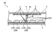
- FIGS. 12A and 12B are partially enlarged cross-sectional views of the encoder 1B according to the second embodiment. Note that FIGS. 12A and 12B show parts corresponding to FIGS. 3A and 3B showing the configuration of the encoder 1 according to the first embodiment.
- each of the plurality of reflection structures 10 is composed of the convex portion 11 and the light reflecting layer 12 formed on the convex portion 11, as shown in FIGS. 12A and 12B.
- each of the plurality of reflection structures 10B is composed of a light reflection layer 12B and a convex lens 11B provided on the light reflection layer 12B. That is, in the present embodiment, the surface of each reflection structure 10B is not the light reflection surface but the surface of the convex lens 11B.
- the light reflecting surface of each reflecting structure 10B is the surface of the light reflecting layer 12B, that is, the interface between the light reflecting layer 12B and the convex lens 11B.
- the convex lens 11B is a semicircular column whose axis is the radial direction of the rotating plate 2. Therefore, the surface of the convex lens 11B is a cylindrical surface that is convex upward.
- the convex lens 11B is made of a transparent material such as a transparent resin material or a transparent glass material.
- the light reflecting layer 12B is a light reflecting film having the same light reflecting characteristics as the light reflecting layer 12 of the encoder 1 in the first embodiment and made of the same material and having a constant thickness.
- the surface (light reflecting surface) of the light reflecting layer 12B is a flat surface.
- each of the plurality of reflective structures 10B configured in this way is a cylindrical surface that is convex upward.
- the convex lens 11B of each of the plurality of reflection structures 10B is integrated, but the present invention is not limited to this.
- the light reflecting layer 12B of each of the plurality of reflecting structures 10B is integrated, but the present invention is not limited to this.
- the materials of the convex lens 11B and the light reflecting layer 12B are the same as those of the convex portion 11 and the light reflecting layer 12 of the reflection structure 10 in the encoder 1 of the first embodiment.
- the plurality of reflective structures 10B have a shape in which irregularities are repeated along the circumferential direction of the rotating plate 2 as a whole.
- the width (width in the column direction) of each of the plurality of reflection structures 10B is the same as that of the encoder 1 of the first embodiment. It is an integral multiple of the width (width in the column direction) of the light reflecting portion 21.
- one reflective structure 10B arranged in the radial direction of the rotating plate 2 one light reflecting portion 21 and one non-light reflecting portion 22 each have the same width.
- the encoder 1B configured in this way operates in the same manner as the encoder 1 in the first embodiment shown in FIG. That is, even in the present embodiment, when the irradiation unit 4 irradiates the light ⁇ toward the rotating rotating plate 2, the light ⁇ emitted from the irradiation unit 4 is sequentially reflected by the plurality of reflection structures 10B arranged in the rotation direction. Light is received by the light receiving unit 5.
- each of the plurality of reflection structures 10B is composed of the light reflection layer 12B and the convex lens 11B
- the light ⁇ emitted from the irradiation unit 4 and incident on the reflection structure 10B is a convex lens. It passes through 11B, is reflected on the surface of the light reflecting layer 12B, passes through the convex lens 11B again, and is emitted to the outside.
- the light incident on the convex lens 11B and the light emitted from the convex lens 11B are refracted and traveled on the outer surface of the convex lens 11B (the interface between the convex lens 11B and the air layer).
- the light ⁇ emitted from the convex lens 11B is incident on the light receiving unit 5 as the reflected light from the reflection structure 10B.
- the relative position of the reflection structure 10B with respect to the irradiation unit 4 changes due to the rotation of the rotating plate 2, the light emitted from the irradiation unit 4 and reaching the reflection structure 10B is emitted. Reflection is performed at a reflection angle corresponding to the curvature of the reflection surface of the reflection structure 10B, and the light is sequentially incident on a plurality of light receiving elements of the light receiving unit 5.
- the reflection structure 10B is reflected only by a slight change in the position of the reflection structure 10B due to the rotation of the rotating plate 2.
- the position of the light reflected by the structure 10B and reaching the light receiving unit 5 can be greatly changed.
- the relative position of the rotating plate 2 with respect to the fixed portion 3 is detected not by the received amount of the reflected light but by the received position of the reflected light.
- the light receiving unit 5 has a plurality of light receiving elements, and the rotation angle (position movement) of the rotating plate 2 is detected by the position of each light receiving element.
- all the light emitted from the irradiation unit 4 is incident on the light receiving element of the light receiving unit 5 without being divided by the number of unit code patterns of the code 20.
- the total amount of one light ray of the light ⁇ emitted from the irradiation unit 4 can be received by the light receiving unit 5, and high angular resolution can be obtained, so that a large detection sensitivity (S / N ratio) can be obtained. ..
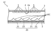
- each of the plurality of reflection structures 10B is composed of a light reflection layer 12B having a flat surface and a convex lens 11B, but the present invention is not limited to this.
- each of the plurality of reflection structures 10C is composed of a light reflection layer 12C having a flat surface and a concave lens 11C provided on the light reflection layer 12C. It may have been done.
- 13A and 13B are partially enlarged cross-sectional views of the encoder 1C according to the modified example of the second embodiment. Note that FIGS. 13A and 13B show parts corresponding to FIGS. 3A and 3B showing the configuration of the encoder 1.
- each reflection structure 10C is the surface of the concave lens 11C.
- the surface of the concave lens 11C is a cylindrical surface that is convex downward.
- the concave lens 11C of each of the plurality of reflection structures 10C is integrated, but the present invention is not limited to this.
- the material of the concave lens 11C is the same as that of the convex lens 11B of the reflection structure 10B in the encoder 1B described above.
- the shape and material of the light reflecting layer 12C are the same as those of the light reflecting layer 12B of the reflecting structure 10B in the encoder 1B described above.
- the width (width in the column direction) of each of the plurality of reflection structures 10C is the light reflecting portion 21 of the code 20 as in the above-mentioned encoder 1B. It is an integral multiple of the width (width in the column direction) of.
- one reflective structure 10C arranged in the radial direction of the rotating plate 2 one light reflecting portion 21 and one non-light reflecting portion 22 each have the same width.
- the encoder 1C configured in this way operates in the same manner as the encoder 1B in the second embodiment. That is, even in this modification, when the irradiation unit 4 irradiates the rotating rotating plate 2 with light, the light emitted from the irradiation unit 4 is sequentially reflected by the plurality of reflection structures 10C arranged in the rotation direction and is sequentially reflected by the light receiving unit 5. Receive light.
- each of the plurality of reflection structures 10C is composed of the light reflection layer 12C and the concave lens 11C
- the light emitted from the irradiation unit 4 and incident on the reflection structure 10C causes the concave lens 11C. It is transmitted, reflected on the surface of the light reflecting layer 12C, transmitted through the concave lens 11C again, and emitted to the outside.
- the light incident on the concave lens 11C and the light emitted from the concave lens 11C are refracted on the outer surface of the concave lens 11C (the interface between the concave lens 11C and the air layer) and proceed.
- the light emitted from the concave lens 11C is incident on the light receiving unit 5 as the reflected light from the reflection structure 10C.
- the surface of each of the plurality of reflective structures 10C is concave, so that the position of the reflective structure 10C is only slightly changed by the rotation of the rotating plate 2, and the reflective structure 10C is used. It is possible to greatly change the position of the light that is reflected by and reaches the light receiving unit 5.
- the light emitted from the irradiation unit 4 can be received by one light receiving element without using the light collecting member 4a. Can be focused on. That is, the same effect as that of the encoder 1B of the second embodiment can be obtained without using the light collecting member 4a.
- the light collecting member 4a may be used in the encoder 1C in the present modification as in the encoder 1B of the second embodiment.
- the light emitted from the irradiation unit 4 can be accurately focused on one light receiving element, so that the rotation angle and the like can be detected with higher sensitivity.
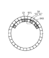
- the irradiation unit 4 irradiates light at a light spot (light irradiation region) that straddles the reflection structures 10 to 10C and the code 20, but the present invention is not limited to this.
- the irradiation unit 4 individually irradiates the reflection structure 10 and the code 20 with light so that the reflection structure 10 and the code 20 have separate light spots. May be good.
- the irradiation unit 4 has, for example, a first light emitting element that irradiates the reflection structure 10 with light at the first spot SP1 and a second light emitting element that irradiates the code 20 with light at the second spot SP2. You may. In this way, the position resolution of the reflection structure 10 and the code 20 can be improved by irradiating the light so that the reflection structure 10 and the code 20 have different light spots.
- the code 20 is not limited to, although the code 20 is formed by forming one or more light reflecting portions 21 and one or more non-light reflecting portions 22 in a row.
- the code 20A in the code 20A, one or more light reflecting portions 21 and one or more non-light reflecting portions 22 may be formed in a plurality of rows (three rows in FIG. 15). In this case, as shown in FIG.
- the irradiation unit 4 may irradiate light with a light spot SP that straddles the reflection structure 10 and the unit code pattern of a plurality of rows of the code 20A, but the reflection structure 10 Light may be individually irradiated to the unit code pattern of a plurality of rows of the code 20A.
- a Gray code or the like can be used as the code 20A in a plurality of columns. Further, in the present specification, the method of designating the absolute position by using an M code, a Gray code, or the like has been described, but other methods may be used.
- the rotary encoder has been described as an example, but the present invention is not limited to this.
- the technique of the present disclosure can also be applied to a linear encoder.
- a substrate that moves linearly is used instead of the rotating plate 2, and the reflective structure 10 and the cord 20 are formed on this substrate.
- the code 20 is composed of the light reflecting unit 21 and the non-light reflecting unit 22, but is not limited to this.
- the code 20 may be composed of a light transmitting portion that transmits light and a non-light transmitting portion that does not transmit light.
- the width of each of the plurality of reflection structures 10 is an integral multiple (for example, 1) of the width of the light transmitting portion or the width of the non-light transmitting portion in the code 20.
- the encoder may or may not have a power supply circuit, a battery, or the like. If the encoder does not have a battery, the encoder may be a batteryless encoder having a power generation element.
- the encoder according to the present disclosure is useful for devices and devices that rotate or move linearly, such as motors.
Landscapes
- Physics & Mathematics (AREA)
- General Physics & Mathematics (AREA)
- Optical Transform (AREA)
Abstract
Priority Applications (3)
| Application Number | Priority Date | Filing Date | Title |
|---|---|---|---|
| CN202180073201.2A CN116507885A (zh) | 2020-11-06 | 2021-10-04 | 编码器 |
| JP2022560677A JPWO2022097399A1 (fr) | 2020-11-06 | 2021-10-04 | |
| US18/044,215 US11982550B2 (en) | 2020-11-06 | 2021-10-04 | Encoder |
Applications Claiming Priority (2)
| Application Number | Priority Date | Filing Date | Title |
|---|---|---|---|
| JP2020-185685 | 2020-11-06 | ||
| JP2020185685 | 2020-11-06 |
Publications (1)
| Publication Number | Publication Date |
|---|---|
| WO2022097399A1 true WO2022097399A1 (fr) | 2022-05-12 |
Family
ID=81457808
Family Applications (1)
| Application Number | Title | Priority Date | Filing Date |
|---|---|---|---|
| PCT/JP2021/036540 WO2022097399A1 (fr) | 2020-11-06 | 2021-10-04 | Codeur |
Country Status (4)
| Country | Link |
|---|---|
| US (1) | US11982550B2 (fr) |
| JP (1) | JPWO2022097399A1 (fr) |
| CN (1) | CN116507885A (fr) |
| WO (1) | WO2022097399A1 (fr) |
Citations (12)
| Publication number | Priority date | Publication date | Assignee | Title |
|---|---|---|---|---|
| JPH02115120U (fr) * | 1989-03-01 | 1990-09-14 | ||
| JP2001124537A (ja) * | 1999-09-28 | 2001-05-11 | Snap On Deutschland Holding Gmbh | 回転部材用回転角センサー |
| JP2003240606A (ja) * | 2002-02-20 | 2003-08-27 | Harmonic Drive Syst Ind Co Ltd | 投影型エンコーダ |
| JP2007071732A (ja) * | 2005-09-07 | 2007-03-22 | Fuji Electric Holdings Co Ltd | 光学式絶対値エンコーダ |
| JP2009276113A (ja) * | 2008-05-13 | 2009-11-26 | Mitsutoyo Corp | 絶対位置測長型エンコーダ |
| JP2012037392A (ja) * | 2010-08-06 | 2012-02-23 | Canon Inc | アブソリュートエンコーダ |
| JP2012127820A (ja) * | 2010-12-15 | 2012-07-05 | Canon Inc | アブソリュートロータリーエンコーダ |
| US20120283986A1 (en) * | 2011-05-03 | 2012-11-08 | Ashok Veeraraghavan | System and Method for Measuring Positions |
| JP2012242313A (ja) * | 2011-05-23 | 2012-12-10 | Iai:Kk | エンコーダとアクチュエータ |
| JP2013002874A (ja) * | 2011-06-14 | 2013-01-07 | Canon Inc | エンコーダ |
| JP2013047692A (ja) * | 2012-12-03 | 2013-03-07 | Nikon Corp | エンコーダ及びエンコーダのパターン検出方法 |
| JP2018128413A (ja) * | 2017-02-10 | 2018-08-16 | 信得 曾 | 光学走査式導光エンコーダ |
Family Cites Families (19)
| Publication number | Priority date | Publication date | Assignee | Title |
|---|---|---|---|---|
| AT288050B (de) * | 1968-01-29 | 1971-02-25 | Leitz Ernst Gmbh | Einrichtung zum Messen von Längen oder Winkeln |
| JPH08219812A (ja) * | 1995-02-15 | 1996-08-30 | Canon Inc | 変位情報検出装置、変位情報検出用スケール及びこれを用いたドライブ制御装置 |
| CA2214193A1 (fr) * | 1997-10-20 | 1999-04-20 | Pat Sin Hao | Codeur optique |
| JP4352307B2 (ja) | 2003-02-20 | 2009-10-28 | 株式会社安川電機 | 光学式エンコーダおよび光学式エンコーダ付モータ |
| US7784694B2 (en) * | 2005-11-21 | 2010-08-31 | Avago Technologies General Ip (Singapore) Pte. Ltd. | Reflective encoder with lens on code strip |
| US7507950B2 (en) * | 2006-11-09 | 2009-03-24 | Avago Technologies Ecbu Ip (Singapore) Pte. Ltd. | Encoder with a combined position and index track |
| JP4976823B2 (ja) * | 2006-11-15 | 2012-07-18 | 株式会社ミツトヨ | 光学式エンコーダ |
| IL183471A0 (en) * | 2007-05-28 | 2007-09-20 | Yaskawa Europ Technology Ltd | Absolute encoder |
| WO2011064317A2 (fr) * | 2009-11-26 | 2011-06-03 | Leica Geosystems Ag | Procédé d'étalonnage et procédé de mesure angulaire pour un dispositif de mesure angulaire, ainsi que dispositif de mesure angulaire |
| US8759746B2 (en) * | 2011-07-21 | 2014-06-24 | Szu Cheng SUN | Optical wheel, rotary encoder, linear encoder and method for generating a zeroing signal of a rotary encoder |
| JP6004194B2 (ja) * | 2013-11-05 | 2016-10-05 | 株式会社安川電機 | エンコーダ、エンコーダ付きモータ、サーボシステム |
| JP5999584B2 (ja) * | 2013-11-05 | 2016-09-28 | 株式会社安川電機 | エンコーダ、エンコーダ付きモータ、サーボシステム |
| JP6128328B2 (ja) * | 2013-11-05 | 2017-05-17 | 株式会社安川電機 | エンコーダ、エンコーダ付きモータ、サーボシステム |
| JP5832562B2 (ja) * | 2014-01-24 | 2015-12-16 | ファナック株式会社 | 樹脂製コード板を有する反射型光学式エンコーダ |
| JP6515185B2 (ja) * | 2015-03-05 | 2019-05-15 | アップル インコーポレイテッドApple Inc. | 方向依存光学特性を有する光学エンコーダを有する時計、手首装着型電子デバイス及びウェラブル電子デバイス |
| TWI585372B (zh) * | 2016-02-05 | 2017-06-01 | 曾信得 | 光學掃描式導光編碼器 |
| JP6958237B2 (ja) * | 2017-10-30 | 2021-11-02 | セイコーエプソン株式会社 | エンコーダースケール、エンコーダースケールの製造方法、エンコーダー、ロボット、電子部品搬送装置、プリンターおよびプロジェクター |
| JP7148337B2 (ja) * | 2018-09-14 | 2022-10-05 | キヤノン株式会社 | 位置検出装置、リソグラフィ装置、力覚センサ及び力覚センサを有する装置 |
| JP7206489B2 (ja) * | 2019-03-07 | 2023-01-18 | ミツミ電機株式会社 | 光学モジュール及び光学式エンコーダ |
-
2021
- 2021-10-04 JP JP2022560677A patent/JPWO2022097399A1/ja active Pending
- 2021-10-04 CN CN202180073201.2A patent/CN116507885A/zh active Pending
- 2021-10-04 WO PCT/JP2021/036540 patent/WO2022097399A1/fr active Application Filing
- 2021-10-04 US US18/044,215 patent/US11982550B2/en active Active
Patent Citations (12)
| Publication number | Priority date | Publication date | Assignee | Title |
|---|---|---|---|---|
| JPH02115120U (fr) * | 1989-03-01 | 1990-09-14 | ||
| JP2001124537A (ja) * | 1999-09-28 | 2001-05-11 | Snap On Deutschland Holding Gmbh | 回転部材用回転角センサー |
| JP2003240606A (ja) * | 2002-02-20 | 2003-08-27 | Harmonic Drive Syst Ind Co Ltd | 投影型エンコーダ |
| JP2007071732A (ja) * | 2005-09-07 | 2007-03-22 | Fuji Electric Holdings Co Ltd | 光学式絶対値エンコーダ |
| JP2009276113A (ja) * | 2008-05-13 | 2009-11-26 | Mitsutoyo Corp | 絶対位置測長型エンコーダ |
| JP2012037392A (ja) * | 2010-08-06 | 2012-02-23 | Canon Inc | アブソリュートエンコーダ |
| JP2012127820A (ja) * | 2010-12-15 | 2012-07-05 | Canon Inc | アブソリュートロータリーエンコーダ |
| US20120283986A1 (en) * | 2011-05-03 | 2012-11-08 | Ashok Veeraraghavan | System and Method for Measuring Positions |
| JP2012242313A (ja) * | 2011-05-23 | 2012-12-10 | Iai:Kk | エンコーダとアクチュエータ |
| JP2013002874A (ja) * | 2011-06-14 | 2013-01-07 | Canon Inc | エンコーダ |
| JP2013047692A (ja) * | 2012-12-03 | 2013-03-07 | Nikon Corp | エンコーダ及びエンコーダのパターン検出方法 |
| JP2018128413A (ja) * | 2017-02-10 | 2018-08-16 | 信得 曾 | 光学走査式導光エンコーダ |
Also Published As
| Publication number | Publication date |
|---|---|
| US11982550B2 (en) | 2024-05-14 |
| US20230358574A1 (en) | 2023-11-09 |
| CN116507885A (zh) | 2023-07-28 |
| JPWO2022097399A1 (fr) | 2022-05-12 |
Similar Documents
| Publication | Publication Date | Title |
|---|---|---|
| US6653619B2 (en) | Optical motion encoder with a reflective member allowing the light source and sensor to be on the same side | |
| JP4705363B2 (ja) | 反射性の円筒形表面を利用したエンコーダ | |
| KR101545134B1 (ko) | 회전 각도 센서에 있어 측정 트랙 분산을 위한 광학적 보정용 장치 및 방법 | |
| JP5064049B2 (ja) | バックグラウンドノイズを低減した反射型エンコーダ | |
| JPH06221874A (ja) | 光学式エンコーダ | |
| JP2004340929A (ja) | 光学式ロータリーエンコーダ | |
| JP6263965B2 (ja) | エンコーダ、エンコーダ付きモータ、サーボシステム | |
| JP5999584B2 (ja) | エンコーダ、エンコーダ付きモータ、サーボシステム | |
| JP2005156549A (ja) | 光学式エンコーダ | |
| JP5943238B2 (ja) | エンコーダ、エンコーダ付きモータ、サーボシステム | |
| WO2022097399A1 (fr) | Codeur | |
| KR20040097124A (ko) | 광학 토크 및 각 센서 | |
| JP5068050B2 (ja) | 光学式アブソリュート形ロータリエンコーダ | |
| US7969856B2 (en) | Optical encoding disc having light converging portions and light diverging portions | |
| JP2720012B2 (ja) | エンコーダ | |
| TWI648520B (zh) | 光學編碼裝置 | |
| TW202122867A (zh) | 光學旋轉編碼器 | |
| TWI675187B (zh) | 光學編碼器 | |
| JP5147877B2 (ja) | 光学式エンコーダ用センサ及び光学式エンコーダ | |
| JP6037258B2 (ja) | エンコーダ及びエンコーダ付きモータ | |
| WO2022230665A1 (fr) | Codeur | |
| JP4996212B2 (ja) | 光学式アブソリュート形ロータリエンコーダ | |
| WO1998037383A1 (fr) | Codeur optique | |
| WO2023032704A1 (fr) | Codeur | |
| JP6004193B2 (ja) | エンコーダ、エンコーダ付きモータ、サーボシステム |
Legal Events
| Date | Code | Title | Description |
|---|---|---|---|
| 121 | Ep: the epo has been informed by wipo that ep was designated in this application |
Ref document number: 21888952 Country of ref document: EP Kind code of ref document: A1 |
|
| ENP | Entry into the national phase |
Ref document number: 2022560677 Country of ref document: JP Kind code of ref document: A |
|
| WWE | Wipo information: entry into national phase |
Ref document number: 202180073201.2 Country of ref document: CN |
|
| NENP | Non-entry into the national phase |
Ref country code: DE |
|
| 122 | Ep: pct application non-entry in european phase |
Ref document number: 21888952 Country of ref document: EP Kind code of ref document: A1 |