WO2022092161A1 - フィルタプリーツパック及びエアフィルタユニット - Google Patents
フィルタプリーツパック及びエアフィルタユニット Download PDFInfo
- Publication number
- WO2022092161A1 WO2022092161A1 PCT/JP2021/039689 JP2021039689W WO2022092161A1 WO 2022092161 A1 WO2022092161 A1 WO 2022092161A1 JP 2021039689 W JP2021039689 W JP 2021039689W WO 2022092161 A1 WO2022092161 A1 WO 2022092161A1
- Authority
- WO
- WIPO (PCT)
- Prior art keywords
- filter
- support layer
- pleated pack
- air
- air filter
- Prior art date
- Legal status (The legal status is an assumption and is not a legal conclusion. Google has not performed a legal analysis and makes no representation as to the accuracy of the status listed.)
- Ceased
Links
Images











Classifications
-
- B—PERFORMING OPERATIONS; TRANSPORTING
- B01—PHYSICAL OR CHEMICAL PROCESSES OR APPARATUS IN GENERAL
- B01D—SEPARATION
- B01D46/00—Filters or filtering processes specially modified for separating dispersed particles from gases or vapours
- B01D46/52—Particle separators, e.g. dust precipitators, using filters embodying folded corrugated or wound sheet material
- B01D46/521—Particle separators, e.g. dust precipitators, using filters embodying folded corrugated or wound sheet material using folded, pleated material
-
- B—PERFORMING OPERATIONS; TRANSPORTING
- B01—PHYSICAL OR CHEMICAL PROCESSES OR APPARATUS IN GENERAL
- B01D—SEPARATION
- B01D63/00—Apparatus in general for separation processes using semi-permeable membranes
- B01D63/02—Hollow fibre modules
- B01D63/021—Manufacturing thereof
- B01D63/0231—Manufacturing thereof using supporting structures, e.g. filaments for weaving mats
-
- B—PERFORMING OPERATIONS; TRANSPORTING
- B01—PHYSICAL OR CHEMICAL PROCESSES OR APPARATUS IN GENERAL
- B01D—SEPARATION
- B01D39/00—Filtering material for liquid or gaseous fluids
- B01D39/08—Filter cloth, i.e. woven, knitted or interlaced material
- B01D39/086—Filter cloth, i.e. woven, knitted or interlaced material of inorganic material
-
- B—PERFORMING OPERATIONS; TRANSPORTING
- B01—PHYSICAL OR CHEMICAL PROCESSES OR APPARATUS IN GENERAL
- B01D—SEPARATION
- B01D39/00—Filtering material for liquid or gaseous fluids
- B01D39/14—Other self-supporting filtering material ; Other filtering material
- B01D39/16—Other self-supporting filtering material ; Other filtering material of organic material, e.g. synthetic fibres
-
- B—PERFORMING OPERATIONS; TRANSPORTING
- B01—PHYSICAL OR CHEMICAL PROCESSES OR APPARATUS IN GENERAL
- B01D—SEPARATION
- B01D39/00—Filtering material for liquid or gaseous fluids
- B01D39/14—Other self-supporting filtering material ; Other filtering material
- B01D39/16—Other self-supporting filtering material ; Other filtering material of organic material, e.g. synthetic fibres
- B01D39/1607—Other self-supporting filtering material ; Other filtering material of organic material, e.g. synthetic fibres the material being fibrous
- B01D39/1623—Other self-supporting filtering material ; Other filtering material of organic material, e.g. synthetic fibres the material being fibrous of synthetic origin
-
- B—PERFORMING OPERATIONS; TRANSPORTING
- B01—PHYSICAL OR CHEMICAL PROCESSES OR APPARATUS IN GENERAL
- B01D—SEPARATION
- B01D39/00—Filtering material for liquid or gaseous fluids
- B01D39/14—Other self-supporting filtering material ; Other filtering material
- B01D39/16—Other self-supporting filtering material ; Other filtering material of organic material, e.g. synthetic fibres
- B01D39/1607—Other self-supporting filtering material ; Other filtering material of organic material, e.g. synthetic fibres the material being fibrous
- B01D39/1623—Other self-supporting filtering material ; Other filtering material of organic material, e.g. synthetic fibres the material being fibrous of synthetic origin
- B01D39/163—Other self-supporting filtering material ; Other filtering material of organic material, e.g. synthetic fibres the material being fibrous of synthetic origin sintered or bonded
-
- B—PERFORMING OPERATIONS; TRANSPORTING
- B01—PHYSICAL OR CHEMICAL PROCESSES OR APPARATUS IN GENERAL
- B01D—SEPARATION
- B01D39/00—Filtering material for liquid or gaseous fluids
- B01D39/14—Other self-supporting filtering material ; Other filtering material
- B01D39/16—Other self-supporting filtering material ; Other filtering material of organic material, e.g. synthetic fibres
- B01D39/1692—Other shaped material, e.g. perforated or porous sheets
-
- B—PERFORMING OPERATIONS; TRANSPORTING
- B01—PHYSICAL OR CHEMICAL PROCESSES OR APPARATUS IN GENERAL
- B01D—SEPARATION
- B01D39/00—Filtering material for liquid or gaseous fluids
- B01D39/14—Other self-supporting filtering material ; Other filtering material
- B01D39/20—Other self-supporting filtering material ; Other filtering material of inorganic material, e.g. asbestos paper, metallic filtering material of non-woven wires
- B01D39/2003—Glass or glassy material
- B01D39/2017—Glass or glassy material the material being filamentary or fibrous
-
- B—PERFORMING OPERATIONS; TRANSPORTING
- B01—PHYSICAL OR CHEMICAL PROCESSES OR APPARATUS IN GENERAL
- B01D—SEPARATION
- B01D39/00—Filtering material for liquid or gaseous fluids
- B01D39/14—Other self-supporting filtering material ; Other filtering material
- B01D39/20—Other self-supporting filtering material ; Other filtering material of inorganic material, e.g. asbestos paper, metallic filtering material of non-woven wires
- B01D39/2027—Metallic material
- B01D39/2041—Metallic material the material being filamentary or fibrous
-
- B—PERFORMING OPERATIONS; TRANSPORTING
- B01—PHYSICAL OR CHEMICAL PROCESSES OR APPARATUS IN GENERAL
- B01D—SEPARATION
- B01D46/00—Filters or filtering processes specially modified for separating dispersed particles from gases or vapours
- B01D46/0002—Casings; Housings; Frame constructions
-
- B—PERFORMING OPERATIONS; TRANSPORTING
- B01—PHYSICAL OR CHEMICAL PROCESSES OR APPARATUS IN GENERAL
- B01D—SEPARATION
- B01D46/00—Filters or filtering processes specially modified for separating dispersed particles from gases or vapours
- B01D46/52—Particle separators, e.g. dust precipitators, using filters embodying folded corrugated or wound sheet material
-
- B—PERFORMING OPERATIONS; TRANSPORTING
- B01—PHYSICAL OR CHEMICAL PROCESSES OR APPARATUS IN GENERAL
- B01D—SEPARATION
- B01D46/00—Filters or filtering processes specially modified for separating dispersed particles from gases or vapours
- B01D46/54—Particle separators, e.g. dust precipitators, using ultra-fine filter sheets or diaphragms
- B01D46/543—Particle separators, e.g. dust precipitators, using ultra-fine filter sheets or diaphragms using membranes
-
- B—PERFORMING OPERATIONS; TRANSPORTING
- B01—PHYSICAL OR CHEMICAL PROCESSES OR APPARATUS IN GENERAL
- B01D—SEPARATION
- B01D63/00—Apparatus in general for separation processes using semi-permeable membranes
- B01D63/14—Pleat-type membrane modules
-
- B—PERFORMING OPERATIONS; TRANSPORTING
- B01—PHYSICAL OR CHEMICAL PROCESSES OR APPARATUS IN GENERAL
- B01D—SEPARATION
- B01D69/00—Semi-permeable membranes for separation processes or apparatus characterised by their form, structure or properties; Manufacturing processes specially adapted therefor
- B01D69/10—Supported membranes; Membrane supports
-
- B—PERFORMING OPERATIONS; TRANSPORTING
- B01—PHYSICAL OR CHEMICAL PROCESSES OR APPARATUS IN GENERAL
- B01D—SEPARATION
- B01D69/00—Semi-permeable membranes for separation processes or apparatus characterised by their form, structure or properties; Manufacturing processes specially adapted therefor
- B01D69/12—Composite membranes; Ultra-thin membranes
- B01D69/1213—Laminated layers
-
- B—PERFORMING OPERATIONS; TRANSPORTING
- B01—PHYSICAL OR CHEMICAL PROCESSES OR APPARATUS IN GENERAL
- B01D—SEPARATION
- B01D69/00—Semi-permeable membranes for separation processes or apparatus characterised by their form, structure or properties; Manufacturing processes specially adapted therefor
- B01D69/12—Composite membranes; Ultra-thin membranes
- B01D69/1216—Three or more layers
-
- B—PERFORMING OPERATIONS; TRANSPORTING
- B01—PHYSICAL OR CHEMICAL PROCESSES OR APPARATUS IN GENERAL
- B01D—SEPARATION
- B01D71/00—Semi-permeable membranes for separation processes or apparatus characterised by the material; Manufacturing processes specially adapted therefor
- B01D71/06—Organic material
- B01D71/30—Polyalkenyl halides
- B01D71/32—Polyalkenyl halides containing fluorine atoms
- B01D71/36—Polytetrafluoroethylene
-
- A—HUMAN NECESSITIES
- A62—LIFE-SAVING; FIRE-FIGHTING
- A62B—DEVICES, APPARATUS OR METHODS FOR LIFE-SAVING
- A62B23/00—Filters for breathing-protection purposes
-
- B—PERFORMING OPERATIONS; TRANSPORTING
- B01—PHYSICAL OR CHEMICAL PROCESSES OR APPARATUS IN GENERAL
- B01D—SEPARATION
- B01D2239/00—Aspects relating to filtering material for liquid or gaseous fluids
- B01D2239/02—Types of fibres, filaments or particles, self-supporting or supported materials
- B01D2239/0216—Bicomponent or multicomponent fibres
- B01D2239/0233—Island-in-sea
-
- B—PERFORMING OPERATIONS; TRANSPORTING
- B01—PHYSICAL OR CHEMICAL PROCESSES OR APPARATUS IN GENERAL
- B01D—SEPARATION
- B01D2239/00—Aspects relating to filtering material for liquid or gaseous fluids
- B01D2239/06—Filter cloth, e.g. knitted, woven non-woven; self-supported material
- B01D2239/0604—Arrangement of the fibres in the filtering material
- B01D2239/0622—Melt-blown
-
- B—PERFORMING OPERATIONS; TRANSPORTING
- B01—PHYSICAL OR CHEMICAL PROCESSES OR APPARATUS IN GENERAL
- B01D—SEPARATION
- B01D2239/00—Aspects relating to filtering material for liquid or gaseous fluids
- B01D2239/06—Filter cloth, e.g. knitted, woven non-woven; self-supported material
- B01D2239/0604—Arrangement of the fibres in the filtering material
- B01D2239/0627—Spun-bonded
-
- B—PERFORMING OPERATIONS; TRANSPORTING
- B01—PHYSICAL OR CHEMICAL PROCESSES OR APPARATUS IN GENERAL
- B01D—SEPARATION
- B01D2239/00—Aspects relating to filtering material for liquid or gaseous fluids
- B01D2239/06—Filter cloth, e.g. knitted, woven non-woven; self-supported material
- B01D2239/065—More than one layer present in the filtering material
- B01D2239/0654—Support layers
-
- B—PERFORMING OPERATIONS; TRANSPORTING
- B01—PHYSICAL OR CHEMICAL PROCESSES OR APPARATUS IN GENERAL
- B01D—SEPARATION
- B01D2239/00—Aspects relating to filtering material for liquid or gaseous fluids
- B01D2239/06—Filter cloth, e.g. knitted, woven non-woven; self-supported material
- B01D2239/065—More than one layer present in the filtering material
- B01D2239/0668—The layers being joined by heat or melt-bonding
-
- B—PERFORMING OPERATIONS; TRANSPORTING
- B01—PHYSICAL OR CHEMICAL PROCESSES OR APPARATUS IN GENERAL
- B01D—SEPARATION
- B01D2239/00—Aspects relating to filtering material for liquid or gaseous fluids
- B01D2239/06—Filter cloth, e.g. knitted, woven non-woven; self-supported material
- B01D2239/065—More than one layer present in the filtering material
- B01D2239/0681—The layers being joined by gluing
-
- B—PERFORMING OPERATIONS; TRANSPORTING
- B01—PHYSICAL OR CHEMICAL PROCESSES OR APPARATUS IN GENERAL
- B01D—SEPARATION
- B01D2239/00—Aspects relating to filtering material for liquid or gaseous fluids
- B01D2239/06—Filter cloth, e.g. knitted, woven non-woven; self-supported material
- B01D2239/069—Special geometry of layers
-
- B—PERFORMING OPERATIONS; TRANSPORTING
- B01—PHYSICAL OR CHEMICAL PROCESSES OR APPARATUS IN GENERAL
- B01D—SEPARATION
- B01D2239/00—Aspects relating to filtering material for liquid or gaseous fluids
- B01D2239/08—Special characteristics of binders
- B01D2239/086—Binders between particles or fibres
-
- B—PERFORMING OPERATIONS; TRANSPORTING
- B01—PHYSICAL OR CHEMICAL PROCESSES OR APPARATUS IN GENERAL
- B01D—SEPARATION
- B01D2239/00—Aspects relating to filtering material for liquid or gaseous fluids
- B01D2239/12—Special parameters characterising the filtering material
- B01D2239/1208—Porosity
-
- B—PERFORMING OPERATIONS; TRANSPORTING
- B01—PHYSICAL OR CHEMICAL PROCESSES OR APPARATUS IN GENERAL
- B01D—SEPARATION
- B01D2239/00—Aspects relating to filtering material for liquid or gaseous fluids
- B01D2239/12—Special parameters characterising the filtering material
- B01D2239/1258—Permeability
-
- B—PERFORMING OPERATIONS; TRANSPORTING
- B01—PHYSICAL OR CHEMICAL PROCESSES OR APPARATUS IN GENERAL
- B01D—SEPARATION
- B01D2239/00—Aspects relating to filtering material for liquid or gaseous fluids
- B01D2239/12—Special parameters characterising the filtering material
- B01D2239/1291—Other parameters
-
- B—PERFORMING OPERATIONS; TRANSPORTING
- B01—PHYSICAL OR CHEMICAL PROCESSES OR APPARATUS IN GENERAL
- B01D—SEPARATION
- B01D46/00—Filters or filtering processes specially modified for separating dispersed particles from gases or vapours
- B01D46/52—Particle separators, e.g. dust precipitators, using filters embodying folded corrugated or wound sheet material
- B01D46/521—Particle separators, e.g. dust precipitators, using filters embodying folded corrugated or wound sheet material using folded, pleated material
- B01D46/523—Particle separators, e.g. dust precipitators, using filters embodying folded corrugated or wound sheet material using folded, pleated material with means for maintaining spacing between the pleats or folds
Definitions
- the present invention relates to a filter pleated pack and an air filter unit provided with an air filter filter medium provided with a fluororesin porous membrane.
- the air filter filter medium provided with the fluororesin porous membrane has excellent collection performance of particles such as dust. If the air filter filter medium is incorporated into the frame to form an air filter unit, handleability, commutativity, and the like can be improved. At that time, by folding the air filter filter medium into a pleated shape to form a filter pleated pack, it is possible to improve the filtration area with respect to the ventilation area (opening area of the frame) of the air filter unit.
- Patent Document 1 discloses an example of a filter pleated pack.
- an adhesive or resin is usually used to prevent leakage of particles to be collected from the gap between the side surface of the filter pleated pack and the frame.
- the gap is sealed with a sealing material such as rubber.
- the gap is formed so as to cover the entire exposed portion (end face) of the air filter filter medium folded in a pleated shape. Be sealed.
- the collection efficiency is lowered in the air filter unit obtained by sealing the gap so as to cover only the downstream side.
- the collection efficiency of the air filter unit is improved even when a simplified seal that covers the gap only from the downstream side is applied. It is an object of the present invention to provide a filter pleated pack suitable for suppressing a decrease.
- the present invention A filter pleated pack containing an air filter filter medium folded into a pleated shape.
- the air filter filter medium includes a first fluororesin porous membrane and a first breathable support layer.
- the first breathable support layer is At least one end in the width direction has a ventilation obstruction portion extending along the end and obstructing the ventilation in the width direction in the first breathable support layer.
- the aeration-inhibiting portion is in contact with the first fluororesin porous membrane.
- Filter pleated pack, I will provide a.
- the width direction is the direction in which the pleated wire of the air filter filter medium folded in the pleated shape extends.
- the first breathable support layer may be arranged on the downstream side of the air flow M passing through the air filter filter medium with respect to the first fluororesin porous membrane.
- the invention is: An air filter unit including a filter pleated pack and a frame body that supports the filter pleated pack.
- the filter pleated pack is the filter pleated pack of the present invention.
- Air filter unit, I will provide a.
- the air filter unit when sealing the gap between the side surface of the filter pleated pack and the frame, even when a simplified seal that covers the gap only from the downstream side is applied, the air filter unit is collected.
- a filter pleated pack suitable for suppressing a decrease in efficiency can be obtained.
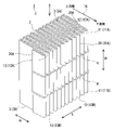
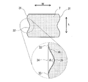
- FIG. 1A is a perspective view schematically showing an example of the filter pleated pack of the present invention.
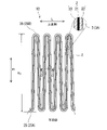
- FIG. 1B is a plan view of a part of one side surface in the width direction of the filter pleated pack of FIG. 1A as viewed along the width direction, and a partially enlarged view of a region including an air filter filter medium and a ventilation blocking portion.
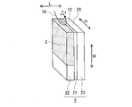
- FIG. 1C is a cross-sectional view showing a cross section CC of the filter pleated pack of FIG. 1B.
- FIG. 2 is a schematic diagram for explaining that a side leak can occur in the absence of a ventilation blocking portion.
- FIG. 3 is a schematic diagram for explaining that side leaks are suppressed in the filter pleated pack of the present invention having a ventilation blocking portion.
- FIG. 1A is a perspective view schematically showing an example of the filter pleated pack of the present invention.
- FIG. 1B is a plan view of a part of one side surface in the width direction of the filter pleated pack of FIG. 1A as viewed
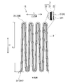
- FIG. 4A is a plan view schematically showing another example of the filter pleated pack of the present invention, and a partially enlarged view of a region including an air filter filter medium and a ventilation blocking portion.
- FIG. 4B is a plan view schematically showing another example of the filter pleated pack of the present invention, and a partially enlarged view of a region including an air filter filter medium and a ventilation blocking portion.
- FIG. 5A is a perspective view schematically showing another example of the filter pleated pack of the present invention.
- FIG. 5B is a plan view of a part of one side surface in the width direction of the filter pleated pack of FIG. 5A as viewed along the width direction, and a partially enlarged view of a region including an air filter filter medium and a ventilation blocking portion.
- FIG. 5C is a cross-sectional view showing a cross section CC of the filter pleated pack of FIG. 5B.
- FIG. 6 is a schematic view for explaining the apex angle ⁇ 1 of the recess that the band-shaped body that the filter pleated pack of the present invention can have on the side surface.
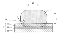
- FIG. 7 is a schematic diagram for explaining a contact angle ⁇ 2 between the band-shaped body that the filter pleated pack of the present invention may have and the air filter filter medium in which the band-shaped body is arranged.
- FIG. 8 is a plan view schematically showing another example of the filter pleated pack of the present invention, and a partially enlarged view of a region including an air filter filter medium and an aeration blocking portion.
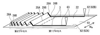
- FIG. 9 is a schematic diagram showing an example of a method for manufacturing the filter pleated pack of the present invention.
- FIG. 10 is a schematic diagram showing another example of the method for manufacturing the filter pleated pack of the present invention.
- FIG. 11 is a schematic diagram showing another example of the method for manufacturing the filter pleated pack of the present invention.
- FIG. 12 is a schematic diagram showing another example of the method for manufacturing the filter pleated pack of the present invention.
- FIG. 13 is a schematic cross-sectional view for explaining an example of a band-shaped body that the filter pleated pack of the present invention may have.
- FIG. 14 is a cross-sectional view schematically showing an example of an air filter filter medium provided in the filter pleated pack of the present invention.
- FIG. 15 is a cross-sectional view schematically showing another example of the air filter filter medium provided in the filter pleated pack of the present invention.
- FIG. 16 is a cross-sectional view schematically showing another example of the air filter filter medium included in the filter pleated pack of the present invention.
- FIG. 17A is a plan view schematically showing an example of the air filter unit of the present invention.
- FIG. 17B is a cross-sectional view showing a cross section BB of the air filter unit of FIG. 17A.
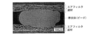
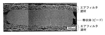
- FIG. 18 is an observation image of the band-shaped body and its vicinity in the filter pleated pack produced in Example 1 by a scanning electron microscope (SEM).
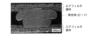
- FIG. 19 is an SEM observation image of the strip-shaped body and its vicinity in the filter pleated pack produced in Example 2.
- SEM scanning electron microscope
- FIG. 20A is an SEM observation image of the strip-shaped body and its vicinity in the filter pleated pack produced in Example 3.
- FIG. 20B is an enlarged image of a portion of the observation image of FIG. 20A in which the band-shaped body and the air filter filter medium are in contact with each other.
- FIG. 21A is an SEM observation image of the strip-shaped body and its vicinity in the filter pleated pack produced in Comparative Example 1.
- FIG. 21B is an enlarged image of a portion of the observation image of FIG. 21A in which the band-shaped body and the air filter filter medium are in contact with each other.
- FIG. 22A is an SEM observation image of the strip-shaped body and its vicinity in the filter pleated pack produced in Comparative Example 2.
- FIG. 22B is an enlarged image of a portion of the observation image of FIG. 22A in which the band-shaped body and the air filter filter medium are in contact with each other.
- FIGS. 1A to 1C An example of the filter pleated pack of this embodiment is shown in FIGS. 1A to 1C.
- FIG. 1B shows a part of the side surface 12 (12A) on one end 11 (11A) side of the width direction W in the filter pleated pack 1 of FIG. 1A as viewed along the width direction W (from the direction B of FIG. 1A). It is a plan view (seen) and a partially enlarged view of a region including an air filter filter medium 2 and a ventilation obstruction portion 3 (3A) on the side surface 12.
- FIG. 1C is a cross-sectional view showing a cross section CC of the filter pleated pack 1 of FIG. 1B.
- FIG. 1B shows a surface of the filter pleated pack 1 that extends in the length direction L and the height direction H.
- FIG. 1C shows a cross section of the filter pleated pack 1 cut along a surface extending in the width direction W and the length direction L.
- the width direction W is the direction in which the pleated wire 25 of the air filter filter medium 2 folded in a pleated shape extends.
- the length direction L is the direction in which the airflow (airflow P) 14 passing through the filter pleated pack 1 is directed (hereinafter referred to as “the direction of the airflow 14”) and the direction orthogonal to the width direction W.
- the height direction H is a direction orthogonal to both the width direction W and the length direction L, and is the direction of the air flow 14.
- the cross section of FIG. 1C is also a cross section viewed along the direction of the air flow 14.
- the same dots are attached to the portions corresponding to the ventilation obstruction portions 3 for the sake of clarity.
- the filter pleated pack 1 of FIGS. 1A to 1C is composed of an air filter filter medium 2 folded in a pleated shape.
- the air filter filter medium 2 includes a first fluororesin porous membrane 21, a first breathable support layer 22, and a second breathable support layer 23.
- the first fluororesin porous membrane 21 is sandwiched by the first breathable support layer 22 and the second breathable support layer 23.
- the first breathable support layer 22 is arranged on one side of the first fluororesin porous membrane 21. More specifically, the first breathable support layer 22 is arranged on the downstream side of the air flow (air flow M) 15 that passes through the air filter filter medium 2 with respect to the first fluororesin porous membrane 21. ..
- the first breathable support layer 22 has a ventilation blocking portion 3 (3A, 3B) at each of both end portions 13 (13A, 13B) in the width direction W.
- the aeration blocking portion 3 extends along the end portion 13 and inhibits the aeration of the widthwise W in the first breathable support layer.
- the aeration obstruction portion 3 is a part of the first aeration support layer 22.
- the aeration blocking portion 3 is located on one side of the first fluororesin porous membrane 21. More specifically, the aeration blocking portion 3 is located on the downstream side of the airflows 14 and 15 with respect to the first fluororesin porous membrane 21.
- the aeration blocking portion 3 is in contact with the first fluororesin porous membrane 21 (in other words, spreads inside the first breathable support layer 22 so as to be in contact with the first fluororesin porous membrane 21. Yes).
- the air filter filter medium 2 is exposed to the gap (unsealed gap) between the side surface 12 and the frame when assembled into the frame.
- a side leak 16 that passes through the end face 24 and further penetrates the inside of the first breathable support layer 22 and escapes to the downstream side of the airflows 14 and 15 may occur.
- the side leak 16 is based on the fact that the first breathable support layer 22 has higher air permeability and lower collection efficiency than the first fluororesin porous membrane 21. According to the studies by the present inventors, the side leak 16 causes the above-mentioned decrease in collection efficiency. On the other hand, as shown in FIG.
- the entire ventilation obstruction portion 3 of FIGS. 1A to 1C is located at the end portion 13. However, at least a part of the ventilation obstruction portion 3 may be located at the end portion 13.
- the end portion 13 in the width direction W of the first breathable support layer 22 means a band-shaped region extending from the end surface 24 toward the center line in the width direction W.
- the width of the region varies depending on the size of the air filter filter medium 2 (size of the filter pleated pack 1), but is, for example, 2 mm or more, 5 mm or more, 10 mm or more, 20 mm or more, 30 mm or more. Further, it may be 40 mm or more.
- the upper limit of the width of the end portion 13 is, for example, 10% or less of the width of the air filter filter medium 2.
- the end portion 11 in the width direction W of the filter pleated pack 1 means a band-shaped region extending from the side surface 12 toward the center line in the width direction W.
- the width of the region varies depending on the size of the filter pleated pack 1, but is, for example, 2 mm or more, even if it is 5 mm or more, 10 mm or more, 20 mm or more, 30 mm or more, or even 40 mm or more. good.
- the upper limit of the width of the end portion 11 is, for example, 10% or less of the width of the filter pleated pack 1.
- the ventilation obstruction portion 3 of FIGS. 1A to 1C reaches the surface (first surface) 91 of the first breathable support layer 22 opposite to the side of the first fluororesin porous membrane 21.
- the ventilation obstruction portion 3 extends inside the first breathable support layer 22 so as to reach from the surface 91 to the first fluororesin porous membrane 21.
- the side leak 16 can be suppressed more reliably.
- the ventilation obstruction portion 3 of FIGS. 1A to 1C extends along the end portion 13 from one end portion 20A of the length direction L in the first breathable support layer 22 to the other end portion 20B. .. In this embodiment, the side leak 16 can be suppressed more reliably.
- the first breathable support layer 22 of FIGS. 1A to 1C has ventilation blocking portions 3A and 3B at both end portions 13A and 13B in the width direction W, respectively.
- the first breathable support layer 22 may have the breathable blocking portion 3 at at least one end 13 in the width direction W.
- the gap 11 of the filter pleated pack 1 in which the ventilation obstruction portion 3 does not exist is sealed so as to cover the entire end surface 24 of the air filter filter medium 2, for example. It is preferable to suppress the side leak 16 at the end portion by a known method such as. The same applies to the end portion of the filter pleated pack 1 in the length direction L. In the cylindrical filter pleated pack 1, both ends in the length direction L may be joined to each other.
- the first resin permeates the first breathable support layer 22 at the at least one end portion 13, and the first resin in the first breathable support layer 22 permeates the ventilation obstruction portion 3.
- the portion 301 may be included (see FIG. 4A). In the portion 301, the permeated first resin reduces the ventilation path of the first breathable support layer 22 and closes depending on the degree of permeation.
- the first breathable support layer 22 is heat-sealed at at least one end portion 13, and the ventilation obstruction portion 3 is a portion of the first breathable support layer 22 that has been heat-sealed.
- 302 may be included (see FIG. 4B).
- the materials constituting the first breathable support layer 22, for example, the fiber material are fused by heat to reduce the ventilation path of the first breathable support layer 22, and depending on the degree of fusion. Block.
- the portions 301 and 302 may extend inside the first breathable support layer 22 so as to reach from the surface 91 to the first fluororesin porous membrane 21.
- FIGS. 5A to 5C Another example of the filter pleated pack 1 of the present embodiment is shown in FIGS. 5A to 5C.
- 5B is a plan view of a part of the side surface 12 (12A) on the one end 11 (11A) side of the width direction W in the filter pleated pack 1 of FIG. 5A as seen along the width direction W, and the side surface 12 It is a partially enlarged view of the region including the air filter filter medium 2 and the ventilation obstruction part 3 in the above.
- FIG. 5C is a cross-sectional view showing a cross section CC of the filter pleated pack 1 of FIG. 5B.
- the 5A to 5C has strips 7 (7A, 7B) extending along the ends 11A, 11B at each of both ends 11 (11A, 11B) in the width direction W. ..
- the strip 7 contains the first resin.
- the strip 7 is arranged on the surface (second surface) of the air filter filter medium 2 folded in a pleated shape on the side of the first breathable support layer 22. More specifically, the strip 7 is arranged on the surface of the air filter filter medium 2 on the downstream side of the air flow 15. Further, the strip 7 penetrates into the inside of the first breathable support layer 22 from the second surface so as to reach the first fluororesin porous film 21 (see FIGS. 5B and 5C). ).
- the ventilation obstruction portion 3 includes a portion of the first breathable support layer 22 in which the band 7 has penetrated.
- the shape of the strip 7 may be strip-shaped when viewed along the direction of the air flow 14.
- the band shape includes a string shape.
- the strip 7 may be the bead of the filter pleated pack 1.
- beads are generally arranged in order to maintain the folded shape (pleated shape) of the air filter filter medium.
- the beads are usually placed on the surface of the air filter filter media so as to travel along the direction intersecting the pleated lines of the folded air filter filter media.
- the strips 7 of FIGS. 5A to 5C are arranged so that the entire strip 7 is in contact with the end portion 11.
- the strip 7 may be arranged so that at least a part thereof is in contact with the end portion 11.
- a part thereof is outward in the width direction W from the end surface 24 on the end 11 side of the air filter filter medium 2. It protrudes in the direction away from the center line.
- the strip-shaped body 7 may be positioned inward in the width direction W (direction approaching the center line) with respect to the end face 24, for example, without protruding outward from the end face 24. ..
- the filter pleated pack 1 of FIGS. 5A to 5C has strips 7A and 7B at both ends 11A and 11B in the width direction W, respectively.
- the filter pleated pack 1 may have a strip 7 at at least one end 11 in the width direction W.
- the strip 7 of FIGS. 5A to 5C is arranged on the surface of the air filter filter medium 2 from the pleated wire 25 (25A) on one side to the pleated wire 25 (25B) on the other side.
- the strip 7 of FIGS. 5A to 5C is a filter medium from the pleated wire 25 (25A) on the downstream side of the airflow 14 in the air filter filter medium 2 to the pleated wire 25 (25B) on the upstream side. It is arranged on the surface of No. 2 (see FIG. 5B). In this embodiment, the side leak 16 can be suppressed more reliably.
- the strip 7 of FIGS. 5A to 5C is the other of the above when viewed from a plane extending in the length direction L and the height direction H, in other words, when viewed from a direction perpendicular to the side surface 12.
- the filter medium is filled with the region 27 between the air filter filter media 2 facing each other on one side. It is arranged on the surface of 2. More specifically, the strips 7 of FIGS. 5A to 5C are viewed from a plane extending in the length direction L and the height direction H, in other words, when viewed from a direction perpendicular to the side surface 12.
- the valley fold line 29 (29B) on the upstream side to the range of 90% or more of the height H 1 between the valley fold lines, the region 27 between the air filter filter media 2 facing each other on the downstream side of the airflows 14 and 15 is filled. As described above, it is arranged on the surface of the filter medium 2 (see FIG. 5B). In this embodiment, the side leak 16 can be suppressed more reliably.
- the strip 7 has a height H between the valley fold lines 29B on the other side (for example, the upstream side as shown in the examples of FIGS. 5A to 5C) when viewed from a direction perpendicular to the side surface 12.
- the valley fold line 29 means an inner fold line in the fold portion 30 of the air filter filter medium 2 folded in a pleated shape.
- the outer bent line in the bent portion 30 is the pleated line 25.
- the height between the valley fold lines H 1 is the valley fold line 29 (for example, the valley fold line 29B) and another valley fold line 29 (for example, the valley fold line 29A on one side of the above) adjacent to the valley fold line 29 along the air filter filter medium 2. ) In the height direction H.
- the valley fold line 29B on the other side of the folded air filter filter medium 2 (for example, the upstream side as shown in the above example) in the strip 7 and the valley fold line 29B adjacent to the valley fold line 29B along the air filter filter medium 2.
- a portion located between the surfaces 37 in contact with the two valley folding lines 29A and 29A'on one side (for example, the downstream side as shown in the above example) (see FIG. 5B; hereinafter, the portion is referred to as a portion X).
- the ratio W 1 / W 0 is, for example, 0.6 or more in the cross section (corresponding to the cross section of FIG. 5C; hereinafter referred to as the cross section Y) viewed along the direction of the airflow 14.
- W 0 is the width of the strip 7 in the cross section Y.
- W 1 is the width of the portion where the strip 7 is in contact with the first fluororesin porous film 21 in the cross section Y. The larger the ratio W 1 / W 0 , the more reliably the side leak 16 can be suppressed.
- the cross section Y may be located at a portion of the strip 7 that fills the region 27.
- the width of the strip 7 means the length in the width direction W.
- the width W 0 can be obtained as the average of the widths in the cross section Y obtained for each of at least three strips 7 selected by changing the valley folding line 29B.
- the width W 1 is the width of the portion where the strip 7 is in contact with the first fluororesin porous film 21 in the cross section Y, which is obtained for each of at least three strips 7 selected by changing the valley folding line 29B. (If there are multiple parts, it can be calculated as the average of the total width of each part).
- the width W 1 of the band-shaped body that does not reach the first fluororesin porous film 21 is 0 (zero).
- the strip 7 is both air filter filter media facing each other on one side (for example, the downstream side of the airflows 14 and 15 as shown in the above example). It is in contact with 2. In this case, the above ratio may be satisfied on at least one contact surface, or the above ratio may be satisfied on both contact surfaces.
- the width W 1 of the portion where the strip 7 is in contact with the first fluororesin porous membrane 21 is, for example, 1.0 mm or more. It may be 1.2 mm or more, 1.4 mm or more, 1.5 mm or more, 1.7 mm or more, 1.9 mm or more, and further 2.0 mm or more.
- the larger the width W 1 the more reliably the side leak 16 can be suppressed.
- the upper limit of the width W 1 is, for example, 5.0 mm.
- the cross section Y of the portion X of the strip 7 as viewed along the direction of the air flow 14 may be flat.
- the band-shaped body 7 shown in FIGS. 5A to 5C corresponds to this aspect.
- the aspect ratio of the flat cross section Y is, for example, less than 1, 0.8 or less, 0.7 or less. , 0.6 or less, 0.5 or less, 0.4 or less, 0.3 or less, and even 0.2 or less.
- the lower limit of the ratio L 0 / W 0 is, for example, 0.1 or more.
- the length L 0 in the vertical direction can be obtained as the average of the lengths in the vertical direction in the cross section obtained for each of at least three strips 7 selected by changing the valley folding line 29B.
- the length in the vertical direction of the strip 7 means the length in the length direction L.
- At least one side surface (side surface in the width direction) 31 of the strip 7 does not have to have a recess, and both side surfaces 31 do not have a recess. It may not have a recess (see FIG. 5C). In this case, the ratio W 1 / W 0 and the width W 1 can be increased more reliably.
- the recess 32 may have an apex angle ⁇ 1 which is an obtuse angle (more than 90 °) (see FIG. 6).
- the apex angle ⁇ 1 of the recess 32 is farthest from both edges 33 of the recess 32 in the cross section and a line segment 34 (corresponding to the tangent to the opening of the recess 32) connecting the edges 33 on the surface of the recess 32. It is defined as the apex angle of the triangle 36 composed of the points (vertices) 35.
- the contact angle ⁇ 2 (see FIG. 7) between the strip 7 and the air filter filter medium 2 may be an obtuse angle (more than 90 °).
- the obtuse angle of the contact angle ⁇ 2 can be determined by observing the cross section Y of the band-shaped body 7 seen along the direction of the air flow 14.
- the contact angle ⁇ 2 is determined as an angle between the surface of the air filter filter medium 2, more specifically, the pleated surface 26.
- the pleated surface refers to a certain pleated wire 25 (for example, the pleated wire 25B) on the surface of the air filter filter medium 2 folded in a pleated shape and adjacent to the pleated wire 25 along the air filter filter medium 2.
- Means the area between and another pleated wire 25 eg, pleated wire 25A).
- the region 27 is filled with the band-shaped body 7 that permeates the first breathable support layer 22 and constitutes the ventilation blocking portion 3.
- the region 27 may be filled with the second resin independently of the aeration blocking portion 3.
- the end portion 11 of the filter pleated pack 1 in the width direction W, in which the first breathable support layer 22 has the airflow blocking portion 3. When 11 is viewed along the width direction W (when viewed from a direction perpendicular to the side surface 12), the air facing each other on one of the above sides (for example, the downstream side of the airflow 15 as shown in the above example).
- the second resin may be arranged so as to fill the region 27 between the filter media 2. Also in this aspect, the side leak 16 can be suppressed more reliably.
- the second resin may be arranged in the region 27 at at least one end portion 11. ..
- FIG. 8 is a plan view of a part of the side surface 12 (12A) on the one end portion 11 (11A) side of the filter pleated pack 1 in the width direction W as seen along the width direction W, as in FIG. 5B. It is a partially enlarged view of the region including the air filter filter medium 2 and the ventilation obstruction part 3 on the side surface 12. The region 27 is filled with the second resin 8.
- the filling of the region 27 with the second resin 8 may be partial.
- the resin of 2 is 50% or more, 60% or more of the height H 1 between the valley fold lines 29B and the valley fold lines located on the other side (for example, the upstream side with respect to the air flow 14 passing through the filter pleated pack 1). It may be arranged so as to fill the region 27 up to a range of 70% or more, 80% or more, and further 90% or more.
- the airflow obstruction unit 3 in FIG. 8 may be the airflow obstruction unit 301 or 302 described above.
- the ventilation obstruction portion 3 is not limited to the above example.
- the first resin and the second resin 8 are, for example, a hot melt resin and a curable resin, and the hot melt resin is preferable from the viewpoint of more reliably ensuring the flexibility of the filter pleated pack 1.
- the first resin and the second resin 8 are not limited to the above examples.
- the photocurable resin may be removed from the first resin and the second resin 8. Since the photocurable resin has a low viscosity in the state before curing, it may be difficult to control the shape of the strip 7 and the filling shape of the resin in the region 27.
- hot melt resins are polyamide resins, polyolefin resins and polyvinyl alcohol resins.
- the ethylene-vinyl acetate copolymer (EVA) resin is included in the polyvinyl alcohol-based resin.
- the first resin and the second resin 8 may be the same or different.
- the filter pleated pack 1 can be manufactured by, for example, the following method. However, the method for manufacturing the filter pleated pack 1 is not limited to the following method.
- FIG. 9 shows an example of a method for manufacturing the filter pleated pack 1.
- the method of FIG. 9 includes a first process and a second process.
- the first process at least one end 62 of the widthwise WM in the filter media raw fabric 61 provided with the first fluororesin porous membrane 21 and the first breathable support layer 22 (in the example of FIG. 9).
- a ventilation blocking portion 3 is formed that extends along the end portion 62 and inhibits the ventilation of the widthwise WM in the first breathable support layer 22.
- the filter medium raw fabric 61 is pleated so that the pleated wire 25 extends in the width direction WM to obtain a filter pleated pack 1.
- the pleated lines 25A and the valley fold lines 29B which are mountain fold lines, are alternately formed on the sheet-shaped filter medium raw fabric 61, and the pleated surfaces 26A, adjacent to each other so as to sandwich the valley fold lines 29B,. 26B stands up.
- the first resin 63 in a flowing state is applied to the surface of the filter medium raw fabric 61 on the side of the first breathable support layer 22, and the applied resin 63 is used as the first breathable support. It penetrates into the layer 22 to form the aeration blocking portion 3.
- the flow state may be a molten state.
- the pleating of the second process can be carried out by a known method, for example, a reciprocating type or a rotary type processing machine.
- the filter medium raw fabric 61 may have the same configuration as the air filter filter medium 2 except that it is not pleated and does not have a ventilation obstructing portion 3.
- FIG. 10 shows another example of the method for manufacturing the filter pleated pack 1.
- the method of FIG. 10 is the same as the method of FIG. 9 except that the aeration blocking portion 3 is formed by heat fusion processing.
- the ventilation obstruction portion 3 is formed by applying heat 64 to at least one end portion 62 of WM in the width direction of the filter media raw fabric 61.
- heat 64 is applied from the side of the first breathable support layer 22 in the filter media raw fabric 61.
- the heat 64 is applied so that, for example, the material constituting the first breathable support layer 22, for example, the fiber material, is melted and fused to each other.
- FIG. 11 shows another example of the method for manufacturing the filter pleated pack 1.
- the method of FIG. 11 is the same as the method of FIG. 9 except that the aeration blocking portion 3 is formed by heat fusion processing.
- heat and pressure are applied by the roller 65 to at least one end 62 of the width direction WM in the filter media raw fabric 61 to form the aeration blocking portion 3.
- the roller 65 is in contact with the side of the first breathable support layer 22 in the filter media raw fabric 61.
- the aeration blocking portion 3 may be formed by performing both the permeation of the first resin and the heat fusion process.
- FIG. 12 shows another example of the method for manufacturing the filter pleated pack 1.
- a band-shaped body 7 containing a hot melt resin is formed.
- the first process and the second process are carried out while the filter media raw fabric 61 is transported from the right side to the left side of the paper surface.
- the resin 41 in a flowing state is applied to the surface of the sheet-shaped filter medium raw fabric 61 on the side of the first breathable support layer 22.
- the resin 41 is usually the same as the resin constituting the strip 7.
- the flow state may be a molten state.
- the resin 41 is typically applied in strips.
- the filter media raw fabric 61 coated with the resin 41 is transported to a second process and pleated.
- the pleated lines 25A and the valley fold lines 29B which are mountain fold lines, are alternately formed and the valley fold lines 29B are interposed.
- the pleated surfaces 26A and 26B rising adjacent to each other so as to be sandwiched between the pleated surfaces 26A and 26B are joined to each other by the resin 41, more specifically, the resin 41A arranged on the pleated surface 26A and the resin 41B arranged on the pleated surface 26B. By doing so, it is fixed.
- the bonded resins 41A and 41B become a strip 7 after cooling.
- the pleating process of the air filter filter medium 2 is performed by repeatedly forming the pleated wire 25A and the valley fold line 29B and fixing the pleated surfaces 26A and 26B by the strips 7.
- the strip 7 can be formed so as to fill the region 27 between the facing air filter filter media 2 on one side (for example, the downstream side of the air flow 15).
- the temperature (coating temperature) of the resin 41 to be applied to the filter media raw fabric 61 is higher than usual. As a result, the viscosity of the resin 41 is lowered, and the penetration of the resin 41 into the first breathable support layer 22 is promoted.
- the coating temperature may be, for example, 10 ° C. or higher, 15 ° C. or higher, 20 ° C. or higher, 25 ° C. or higher, and even 30 ° C. or higher higher than the normal coating temperature.
- the specific coating temperature varies depending on the type of the resin 41, but when the resin 41 is an EVA resin, it may be, for example, 150 to 180 ° C. or 160 to 170 ° C.
- the coating width of the resin 41 to be coated on the filter media raw fabric 61 is larger than usual.
- the coating width is, for example, + (plus) 0.3 mm as compared with the normal coating width, and may be +0.5 mm, +0.7 mm, +1.0 mm, +1.2 mm, or even +1.4 mm.
- the specific coating width varies depending on the type of the resin 41 and the coating temperature, but when the resin 41 is an EVA resin and the coating temperature is 150 ° C.
- the upper limit of the coating width is not limited as long as the filtration area required for the filter pleated pack 1 can be secured, and is, for example, 5.0 mm or less.
- the strip 7 By raising the coating temperature of the resin 41 coated on the air filter filter medium 2 in the first process of FIG. 12 and / or increasing the coating width, for example, the strip 7 satisfying the above range of the ratio W 1 / W 0 . And the formation of the strip 7 that satisfies the range of the width W 1 is more reliable.
- the strip 7 is formed by joining the resin 41A coated on the pleated surface 26A and the resin 41B coated on the pleated surface 26B to each other in the second process and cooling the strip-shaped body 7.
- the previously applied resin 41A has a lower temperature at the time of joining, in other words, the resin 41A has a lower fluidity at the time of joining. Therefore, as shown in FIG. 13, the strip-shaped body 7 formed by joining retains the shape at the time of application, for example, a string shape having a circular or elliptical cross section in the portion 42A derived from the resin 41A. It is easy to form a strongly deformed cross section in the portion 42B derived from the resin 41B.
- the temperature decrease of the resin 41A is delayed, so that the portion 42A derived from the resin 41A is also formed. Deformation at the time of joining is promoted. This makes it more reliable to form, for example, a strip 7 having a flat cross section Y or a strip 7 having at least one side surface 31 having no recess 32 in the cross section Y. In the cross section Y of the strip 7 shown in FIG. 13, both side surfaces 31 of the strip 7 have recesses 32 having an acute angle ⁇ 1 . Further, in the cross section Y, the width W 2 of the portion 42A derived from the resin 41A substantially maintains the coating width of the resin 41A.
- the method for manufacturing the filter pleated pack shown in each of the above examples is as follows. Along with extending along the end 62 with respect to at least one end 62 of the widthwise WM in the filter media raw fabric 61 provided with the first fluororesin porous membrane 21 and the first breathable support layer 22. To form a ventilation blocking portion 3 that inhibits the ventilation of WM in the width direction in the first breathable support layer 22. It includes pleating the filter medium raw fabric 61 so that the pleated wire 25 extends in the width direction WM to obtain the filter pleated pack 1.
- the strip 7 may or may not be arranged on the other side of the filter pleated pack 1 (for example, the upstream side of the air flow 14).
- the strip 7 is not arranged on the other side.
- no other members other than the strip 7 are arranged on the other side of the ends 11A and 11B in the width direction W. At the ends 11A and 11B in the width direction, the surface on the other side of the air filter filter medium 2 is exposed.
- the air filter filter medium 2 of FIG. 14 is a filter medium included in each of the filter pleated packs 1 shown above, and the second breathable support layer 23 and the first fluorine are provided from the upstream side of the air flow 15 passing through the air filter filter medium 2. It has a three-layer structure in which the resin porous membrane 21 and the first breathable support layer 22 are arranged in order. The second breathable support layer 23 and the first fluororesin porous membrane 21 are bonded to each other. The first fluororesin porous membrane 21 and the first breathable support layer 22 are joined to each other. In the air filter filter medium 2 of FIG. 14, one outermost layer (the layer into which the airflow 15 flows) is the second breathable support layer 23, and the other outermost layer (the layer from which the airflow 15 is discharged) is the first. The breathable support layer 22.
- the first fluororesin porous membrane 21 is a layer that can function as the main filter of the air filter filter medium 2.
- the fluororesin porous membrane 21 is typically composed of innumerable fluororesin fibrils, which are fine fibrous structures.
- the fluororesin porous membrane 21 may have a fluororesin node (nodule) connected to the fibril.
- the fluororesin porous membrane 21 is mainly composed of fluororesin. "Mainly composed of fluororesin” means that the content of fluororesin is the largest among all the components contained in the fluororesin porous membrane 21.
- the content of the fluororesin in the fluororesin porous membrane 21 is, for example, 50% by weight or more, 60% by weight or more, 70% by weight or more, 80% by weight or more, 90% by weight or more, and further 95% by weight or more. You may.
- the fluororesin porous membrane 21 may contain, for example, a filler in addition to the fluororesin.
- fluororesins examples include PTFE, ethylene-tetrafluoroethylene-hexafluoropropylene copolymer (EFEP), tetrafluoroethylene-hexafluoropropylene-vinylidene fluoride copolymer (THV), and tetrafluoroethylene-hexafluoropropylene.
- FEP ethylene-tetrafluoroethylene-hexafluoropropylene copolymer
- TSV tetrafluoroethylene-hexafluoropropylene-vinylidene fluoride copolymer
- ETFE ethylene-tetrafluoroethylene copolymer
- the fluororesin porous membrane 21 may contain two or more kinds of fluororesins.
- the fluororesin porous membrane 21 may be a PTFE porous membrane.
- the fluororesin porous film 21 is formed by, for example, forming a mixture of an unfired fluororesin powder and a liquid lubricant into a film by a method such as extrusion and / or rolling, and liquid lubricating the obtained unfired film. It can be formed by removing the agent and then stretching it. After forming the unfired film, firing may be performed by heating the film to a temperature equal to or higher than the melting point of the fluororesin at an arbitrary timing.
- liquid lubricants are hydrocarbon oils such as naphtha, white oil and liquid paraffin. However, the liquid lubricant is not limited as long as it can wet the surface of the fluororesin powder and can be removed later.
- stretching examples include stretching of an unfired film at a stretching ratio of 2 to 60 times with respect to MD (longitudinal direction) and a stretching temperature of 150 to 390 ° C., and stretching ratio of the film with respect to TD (width direction) of 10 to 60 times and stretching temperature. It is a biaxial stretching in combination with stretching at 40 to 150 ° C.
- the method for manufacturing the fluororesin porous membrane 21 is not limited as long as the collection performance according to the intended use of the filter pleated pack 1 and the air filter unit provided with the filter pleated pack 1 can be obtained.
- the thickness of the fluororesin porous membrane 21 is, for example, 0.1 to 100 ⁇ m, 0.5 to 80 ⁇ m, and further may be 1 to 50 ⁇ m.
- the basis weight of the fluororesin porous membrane 21 is, for example, 0.05 to 10 g / m 2 , 0.1 to 5 g / m 2 , and further may be 0.3 to 3 g / m 2 .
- the pressure loss PD of the fluororesin porous membrane 21 at a permeation flow rate of 5.3 cm / sec is, for example, 10 to 500 Pa, 20 to 400 Pa, and may be 40 to 350 Pa.
- the pressure loss PD of each layer constituting the air filter filter medium 2 and the air filter filter medium 2 can be evaluated as follows.
- the filter medium or layer to be evaluated is set in a circular holder having an effective area of 100 cm 2 .
- air is permeated through the set evaluation object, and the pressure loss when the linear velocity of the passing air is adjusted to 5.3 cm / sec with a flow meter is measured with a pressure gauge (manometer).
- the pressure loss is measured 8 times for one evaluation object, and the average thereof is defined as the pressure loss PD.
- polyalphaolefin (PAO) particles which are polydisperse particles having a number peak in the particle size range of 0.1 to 0.2 ⁇ m, are used.
- the collection efficiency CE measured under the conditions of the evaluation target particle size of 0.1 to 0.2 ⁇ m and the permeation flow velocity of 5.3 cm / sec is, for example, 60 to 99.99999%, 90 to 99.99999%, and further 99. It may be up to 99.999%.
- the collection efficiency CE of each layer constituting the air filter filter medium 2 and the air filter filter medium 2 can be evaluated as follows.
- the filter medium or layer to be evaluated is set in a circular holder having an effective area of 100 cm 2 .
- air is permeated through the set evaluation object, and the linear velocity of the passing air is adjusted to 5.3 cm / sec with a flow meter.
- the polydisperse PAO particles are included in the air passing through the evaluation object so that the concentration of the particles having a particle size of 0.1 to 0.2 ⁇ m is 4 ⁇ 10 8 particles / L or more.
- Polydisperse PAO particles can be generated using, for example, a constant power aerosol atomizer.
- the concentration of polydisperse PAO particles contained in the air that passed through the evaluation target was determined for the range of the evaluation target particle size, and the evaluation target was calculated by the following formula (2).
- the particle concentration of the formula (2) is the concentration of the particles in the range of the particle size to be evaluated on both the upstream side and the downstream side.
- the particle concentration on the upstream side can be obtained by flowing the air containing the polydisperse PAO particles in a state where the evaluation target is not set in the holder, and analyzing this with the particle counter.
- the PF (Performance Factor) value obtained by the following formula (3) is, for example, 20 or more, 22 or more, 23 or more, 25 or more, 27 or more, 28 or more, and further 30 or more. It may be.
- the upper limit of the PF value is, for example, 40 or less, and may be 38 or less, 36 or less, and further 35 or less.
- the PD of the formula (3) is the pressure loss, and the CE is the collection efficiency.
- the unit of the pressure loss PD in the formula (3) is mmH 2 O.
- PF value ⁇ -l Albanyg [(100-CE) / 100] / PD ⁇ x 100 (3)
- the fluororesin porous membrane 21 in FIG. 14 is a single layer.
- the fluororesin porous film 21 may be a laminate of two or more identical or different films.
- the fluororesin porous membrane 21 of FIG. 14 is in contact with the first breathable support layer 22.
- Another layer may be arranged between the fluororesin porous membrane 21 and the first breathable support layer 22.
- the one in which the fluororesin porous membrane 21 and the first breathable support layer 22 are in contact with each other without arranging another layer is, for example, the fluororesin porous membrane 21 at the time of forming the strip 7. The penetration of the resin 41 until it reaches is more reliable.
- the fluororesin porous membrane 21 of FIG. 14 is in contact with the second breathable support layer 23.
- Another layer may be arranged between the fluororesin porous membrane 21 and the second breathable support layer 23.
- the fluororesin porous membrane 21 may be a fluororesin porous membrane provided in a known air filter filter medium.
- the first breathable support layer 22 functions as a layer that supports the fluororesin porous film 21 from the one side (for example, the downstream side of the air flow 15).
- the breathable support layer 22 is made of, for example, a fiber material.
- a fiber material that can form the breathable support layer 22 is at least one selected from glass fiber, resin fiber and metal fiber.
- resin fibers include polyolefin fibers such as polyethylene (PE) fibers and polypropylene (PP) fibers, polyester fibers such as polyethylene terephthalate (PET) fibers and polyethylene naphthalate fibers, acrylic fibers such as acrylonitrile fibers, and aromatic polyamide fibers. It is a polyamide fiber containing.
- the resin fiber may be a composite fiber of two or more resins.
- An example of a composite fiber is a fiber having a core-sheath structure including a core portion and a sheath portion covering the core portion.
- the melting point of the sheath may be lower than the melting point of the core.
- a specific example of the composite fiber is a fiber composed of a core portion of PET and a sheath portion of PE. In this case, since the adhesiveness of PE to the fluororesin porous membrane 21 is excellent, the bonding between the breathable support layer 22 and the fluororesin porous membrane 21 is more reliable.
- the breathable support layer 22 may be a non-woven fabric of resin fibers.
- non-woven fabrics are melt blown non-woven fabrics and spunbonded non-woven fabrics. Since the pressure loss PD of the air filter filter medium 2 can be reduced, the nonwoven fabric may be a spunbonded nonwoven fabric.
- the breathable support layer 22 may contain a material other than the fiber material.
- An example of the material is a binder that binds the fibers of the fiber material together.
- the binder is typically a resin. Examples of resins are acrylic resins, polyvinyl alcohol and polyethylene oxide.
- the thickness of the breathable support layer 22 is, for example, 10 to 2000 ⁇ m, 50 to 1000 ⁇ m, and may be 100 to 500 ⁇ m.
- the basis weight of the breathable support layer 22 is, for example, 10 g / m 2 or more, 50 g / m 2 or more, and may be 100 g / m 2 or more.
- the upper limit of the basis weight is, for example, 500 g / m 2 or less.
- the breathable support layer 22 has higher breathability in the thickness direction than the fluororesin porous membrane 21, and has lower collection efficiency.
- the pressure loss PD of the breathable support layer 22 at a permeation flow rate of 5.3 cm / sec is, for example, 0.1 to 100 Pa, 0.1 to 80 Pa, and further may be 0.1 to 50 Pa.
- the collection efficiency CE measured for the breathable support layer 22 using polydisperse PAO particles under the conditions of a particle size to be evaluated of 0.3 to 0.5 ⁇ m and a permeation flow rate of 5.3 cm / sec is, for example, 0.1 to. It is 50%, 0.5 to 20%, and may be 1 to 5%.
- the breathable support layer 22 in FIG. 14 is a single layer.
- the breathable support layer 22 may be a laminate of two or more identical or different layers.
- the breathable support layer 22 may be a breathable support layer provided in a known air filter filter medium.
- the second breathable support layer 23 is arranged on the other side (for example, the upstream side of the air flow 15) with respect to the first fluororesin porous membrane 21 and together with the first breathable support layer 22. It sandwiches the first fluororesin porous film 21.
- the second breathable support layer 23 functions as a layer that supports the first fluororesin porous film 21 from the other side.
- the breathable support layer 23 may have the above-mentioned configurations and / or characteristics in any combination in the description of the first breathable support layer 22.
- the breathable support layer 23 may be the same as the first breathable support layer 22.
- the structure of the air filter filter medium 2 includes a first fluororesin porous membrane 21 and a first breathable support layer 22, and the first breathable support layer 22 is relative to the first fluororesin porous membrane 2. It is not limited as long as it is arranged on one side (for example, the downstream side of the air flow 15).
- FIG. 15 shows another example of the air filter filter medium 2.
- the air filter filter medium 2 of FIG. 15 has a two-layer structure in which the first fluororesin porous membrane 21 and the first breathable support layer 22 are sequentially arranged from the upstream side of the air flow 15 passing through the air filter filter medium 2. Have. The first fluororesin porous membrane 21 and the first breathable support layer 22 are joined to each other. In the air filter filter medium 2 of FIG. 15, one outermost layer (the layer into which the airflow 15 flows) is the first fluororesin porous membrane 21, and the other outermost layer (the layer from which the airflow 15 is discharged) is the first.
- FIG. 16 shows another example of the air filter filter medium 2.
- the air filter filter medium 2 of FIG. 16 has the same configuration as the air filter filter medium 2 of FIG. 14 except that the second fluororesin porous membrane 28 is further provided.
- the second fluororesin porous membrane 28 is arranged on the other side (for example, the upstream side of the air flow 15) with respect to the first fluororesin porous membrane 21.
- the first fluororesin porous membrane 21 is located on one of the above-mentioned one side (for example, the most downstream side with respect to the air flow 15) among all the fluororesin porous membranes included in the air filter filter medium 2 of FIG. ..
- the 16 has a second fluororesin porous membrane 28, a second breathable support layer 23, a first fluororesin porous membrane 21, and a first breathability from the upstream side of the air flow 15. It has a four-layer structure in which the support layers 22 are arranged in order.
- the second fluororesin porous membrane 28 may have the above-mentioned configurations and / or characteristics in any combination in the description of the first fluororesin porous membrane 21.
- the second fluororesin porous membrane 28 may be the same as the first fluororesin porous membrane 21. Further, the second fluororesin porous membrane 28 may have a lower pressure loss PD and / or a collection efficiency CE as compared with the first fluororesin porous membrane 21, and in this case, the second fluororesin porous membrane 28 may have a lower pressure loss PD and / or a collection efficiency CE.
- the second fluororesin porous membrane 28 in FIG. 16 is in contact with the second breathable support layer 23.
- Another layer may be arranged between the second fluororesin porous membrane 28 and the second breathable support layer 23.
- one outermost layer (the layer into which the airflow 15 flows) is the second fluororesin porous membrane 28, and the other outermost layer (the layer from which the airflow 15 is discharged) is the first.
- the number of fluororesin porous membranes and breathable support layers included in the air filter filter medium 2 is not limited to the above example.
- a further breathable support layer may be arranged on the upstream side of the air flow 15 with respect to the second fluororesin porous membrane 28.
- the air filter filter medium 2 may include additional layers and / or members other than those described above.
- an arbitrary layer such as a pre-filter layer may be arranged on the upstream side of the air flow 15 with respect to the first fluororesin porous membrane 21 and / or the second fluororesin porous membrane 28.
- the thickness of the air filter filter medium 2 is, for example, 50 to 4000 ⁇ m, 100 to 2000 ⁇ m, and may be 200 to 1000 ⁇ m.
- the basis weight of the air filter filter medium 2 is, for example, 10 to 1000 g / m 2 , 20 to 500 g / m 2 , and further 50 to 200 g / m 2 .
- the pressure loss PD of the air filter filter medium 2 at a permeation flow rate of 5.3 cm / sec is, for example, 10 to 500 Pa, 20 to 400 Pa, and further 40 to 350 Pa.
- the collection efficiency CE measured using polydisperse PAO particles under the conditions of a particle size to be evaluated of 0.1 to 0.2 ⁇ m and a permeation flow rate of 5.3 cm / sec is, for example, 60 to 99.99999. %, 90 to 99.9999%, and further may be 99 to 99.999%.
- the PF value obtained by the above formula (3) is, for example, 20 or more, and may be 22 or more, 23 or more, 25 or more, 27 or more, 28 or more, or even 30 or more.
- the upper limit of the PF value is, for example, 40 or less, and may be 38 or less, 36 or less, and further 35 or less.
- Each layer of the air filter filter medium 2 is joined to each other.
- Each layer constituting the air filter filter medium 2 for example, a fluororesin porous membrane and a breathable support layer can be joined by thermal laminating or laminating with an adhesive. Since it is possible to suppress an increase in pressure loss at the joint portion, joining by thermal laminating is preferable.
- the air filter filter medium 2 can be formed by joining a fluororesin porous membrane and a breathable support layer.
- the air filter filter medium 2 may be a known air filter filter medium.
- the filter pleated pack of the present invention may include additional members other than those described above.
- Each of the above-illustrated filter pleated packs 1 further includes a bead 4 located at a position other than the end portion 11 in the width direction W.
- the configuration of the bead 4 may be the same as the configuration of the conventional bead, or may be the same as the configuration of the strip 7.
- the position, number and extending direction of the bead 4 are not limited.
- Bead 4 is usually composed of resin.
- the example of the resin constituting the bead 4 is the same as the example of the resin that can be contained in the strip 7.
- the bead 4 and the strip 7 may be made of the same resin.
- the filter pleated pack 1 can be used as an air filter unit by incorporating it into a frame, for example. However, the use of the filter pleated pack 1 is not limited to the above example.
- the filter pleated pack 1 can be used, for example, as a mask, a filter for a vacuum cleaner, or a filter for a cabin of a vehicle such as an automobile by making the size suitable for the application.
- FIGS. 17A and 17B An example of the air filter unit of the present invention is shown in FIGS. 17A and 17B.
- FIG. 17A is a plan view of the airflow (airflow F) 19 passing through the air filter unit 1 as seen from the downstream side.
- the direction of the airflow 19 and the direction of the airflow 14 passing through the filter pleated pack 1 are usually the same.
- FIG. 17B is a cross-sectional view showing a cross section BB of the air filter unit 51 of FIG. 17A.
- the air filter unit 51 of FIGS. 17A and 17B includes a filter pleated pack 1 and a frame body (support frame) 52 that supports the filter pleated pack 1. In the air filter unit 51, the peripheral edge portion of the filter pleated pack 1 is supported by the frame body 52.
- the filter pleated pack 1 of FIGS. 17A and 17B has a strip 7 (7A, 7B) at each of both ends 11 (11A, 11B) in the width direction W.
- the arranged end 11 of the filter pleated pack 1 in which the strip 7 is arranged is on one side of the end 11 (in other words For example, as shown in the examples of FIGS. 17A and 17B, it is joined to the frame 52 in the region (downstream side of the airflow 19).
- the region on the other side of the end portion 11 (for example, the upstream side of the airflow 19 as shown in the examples of FIGS. 17A and 17B) is not joined to the frame 52.
- the filter pleated pack 1 and the frame 52 are joined by a sealing material 53, and the sealing material 53 has a gap between the side surface 12 on the end 11 side of the filter pleated pack 1 and the frame 52.
- the downstream side of the airflow 19 is arranged so as to cover the side. However, the entire gap is not covered by the sealing material 53, and there is an unsealed gap 54 between the area on the other side of the side surface 12 and the frame 52. The end face 24 of the air filter filter medium 2 is exposed in the gap 54.
- the side leak 16 is suppressed and the decrease in the collection efficiency is suppressed even though the gap 54 exists between the side surface 12 and the frame body 52.
- the region on one side and the region on the other side (for example, the region on the downstream side and the region on the upstream side of the airflow 19) in the end portion 11 are, for example, when viewed from a direction perpendicular to the side surface 12.
- the pleated height H 0 means a pleated wire 25 (for example, a pleated wire 25B) and another pleated wire 25 (for example, a pleated wire 25A) adjacent to the pleated wire 25 along the air filter filter medium 2. It is a separation distance in the height direction H between the two (see FIG. 1B).
- At least one end 11 of the filter pleated pack 1 in the width direction W in which the first breathable support layer 22 has the air flow blocking portion 3 is one of the above in the end 11. It may be joined to the frame 52 in the region on the side (for example, the downstream side of the airflow 19 as shown in the above example). Further, the region of the at least one end 11 on the other side (for example, the upstream side of the airflow 19 as shown in the above example) may not be joined to the frame 52.
- the sealing material 53 is also arranged on the main surface 17 on one side (for example, the downstream side of the airflow 19) of the end portion 11.
- the sealing material 53 is arranged so as to cover the entire band-shaped body 7 when viewed from the downstream side of the airflow 19 along the direction of the airflow 19. Even if the sealing material 53 to be joined on the main surface 17 on the downstream side is arranged so as to cover a part of the strip 7 when viewed from the downstream side of the airflow 19 along the direction of the airflow 19. good.
- the mode of joining with the frame 52 in the region on one side of the end portion 11 is not limited to the above example.
- the joining with the frame 52 may be performed only in a part of the region on one side of the above. Further, the joint with the frame body 52 may be made only between the side surface 12 on the end portion 11 side of the filter pleated pack 1.
- the joining mode can be selected, for example, according to the shape (including the cross-sectional shape) of the frame 52.
- sealing material 53 a material used for joining the filter pleated pack and the frame in the conventional air filter unit, for example, an adhesive, a resin, a rubber, or the like can be used.
- a specific example of the sealing material 53 is a hot melt resin.
- the method of joining the end portion 11 and the frame body 52 is not limited to the above example.
- the end 18 in the length direction L of the filter pleated pack 1 can be joined to the frame 52 by a known method.
- the filter pleated pack 1 may be curved and both end portions 18 may be joined to form a cylindrical filter pleated pack 1. Both end portions 18 may be joined so that the end surface 24 of the air filter filter medium 2 at each end portion 18 is covered with a sealing material 53 or the like.
- the surface on the upstream side with respect to the air flow 14 may be the outer peripheral surface, and the surface on the downstream side may be the inner peripheral surface.
- Examples of materials constituting the frame 52 are resins, metals, and composite materials thereof.
- the frame 52 of FIGS. 17A and 17B is the end portion 11 in which the strip-shaped body 7 in the filter pleated pack 1 is arranged (in other words, the first breathable support layer 22 has the ventilation blocking portion 3). It has a shape that covers the side surface 12 on the side of.
- the configuration of the air filter unit of the present invention is not limited to the above example.
- the pressure loss of the air filter unit 51 is, for example, 10 to 1000 Pa, 20 to 400 Pa, and may be 50 to 200 Pa.
- the pressure loss of the air filter unit 51 can be obtained in accordance with the pressure loss test of the test method type 1 defined in Japanese Industrial Standards (former Japanese Industrial Standards; JIS) B9908: 2011.
- the collection efficiency of the air filter unit 51 is, for example, 60 to 99.999999%, 90 to 99.99999%, and further may be 99 to 99.9999%.
- the collection efficiency of the air filter unit 51 can be evaluated by the following measurement conditions and methods in accordance with the method defined in European Standard (EN) 1822-1: 2009. However, the collection efficiency obtained by using the polydisperse PAO particles as the test particles is used as the collection efficiency of the air filter unit, not the collection efficiency with respect to the maximum permeation particle diameter (MPPS).
- MPPS maximum permeation particle diameter
- the particle concentration is the concentration of PAO particles in the range of the particle size to be evaluated on both the upstream side and the downstream side.
- the air filter unit 51 may be a unit composed of a HEPA (high-efficiency particulate air grade) filter or a ULPA (ultra-low penetration air grade) filter defined in JIS Z8122: 2000.
- HEPA high-efficiency particulate air grade
- ULPA ultra-low penetration air grade
- PTFE porous membrane A mixture was obtained by uniformly mixing 100 parts by weight of PTFE fine powder (manufactured by Daikin, Polyflon PTFE F-104) and 20 parts by weight of dodecane as a liquid lubricant. Next, the obtained mixture was extruded into a rod shape by an extruder and further rolled by a pair of metal rolling rolls to obtain a PTFE sheet having a thickness of 200 ⁇ m. Next, the PTFE sheet obtained by rolling was held in an atmosphere of 150 ° C. to remove the liquid lubricant, and the PTFE sheet was stretched in the longitudinal direction at a stretching temperature of 280 ° C.
- the film was stretched in the width direction at a stretching temperature of 120 ° C. and a stretching ratio of 35 times to obtain an unfired PTFE porous film.
- the obtained porous membrane was calcined at 400 ° C. using a hot air generator to obtain a strip-shaped PTFE porous membrane.
- the thickness of the obtained PTFE porous membrane was 1.0 ⁇ m, the pressure loss was 140 Pa, the collection efficiency (evaluation target particle size 0.1 to 0.2 ⁇ m) was 99.995%, and the PF value was 31.
- a spunbonded non-woven fabric (manufactured by Unitika Ltd., Elves S303WDO) composed of PET / PE composite fibers was prepared.
- This PET / PE composite fiber has a core-sheath structure including a core portion of PET and a sheath portion of PE.
- the thickness of the breathable support layer was 150 ⁇ m
- the basis weight was 30 g / m 2
- the pressure loss was 0.1 Pa
- the collection efficiency evaluation target particle size 0.3 to 0.5 ⁇ m
- the prepared or prepared PTFE porous membrane and breathable support layer are laminated so that a pair of breathable support layers sandwich the PTFE porous membrane, and heat-laminated by a roll held at 130 ° C. to obtain a breathable support layer.
- An air filter filter medium having a three-layer structure of / PTFE porous membrane / breathable support layer was obtained.
- Example 1 The method of FIG. 12 was carried out on the air filter filter medium produced above, and the filter pleated pack 1 (width 50 mm, width 50 mm, shown in FIGS. 5A to 5C) provided with strips 7 which are beads at both ends 11 in the width direction. A length of 100 mm, a pleated height of H 0 15 mm, and a number of pleats of 5 / cm) were obtained. A reciprocating pleating machine was used for pleating. The coating width of the resin 41 to be coated in the first process was 1.5 mm, and the coating temperature was 160 ° C. The application of the resin 41 was carried out on the surface of one of the breathable support layers in the air filter filter medium.
- FIG. 18 shows an SEM observation image of the strip 7 and its vicinity in the prepared filter pleated pack.
- the observation image of FIG. 18 shows a cross section Y of the portion X of the strip 7 as viewed along the direction of the air flow 14.
- the strip 7 permeated the breathable support layer coated with the resin 41 on both pleated surfaces 26A and 26B in contact with the strip 7 and reached the PTFE porous membrane.
- the width W 0 of the strip 7 evaluated from the three observation images including the observation image of FIG.
- the produced filter pleated pack is fitted into the frame so that the forming surface of the strip 7 is on the downstream side of the air flow 19, and the gap between the side surface and the frame at both ends in the width direction of the filter pleated pack.
- a hot melt resin was poured into the airflow 19 from the downstream side, and the filter pleated pack and the frame were joined only in the downstream region at the end portion to obtain the air filter unit shown in FIGS. 17A and 17B.
- upstream particle concentration was 1.0 ⁇ 10 8 particles / L
- Example 2 The filter pleated pack shown in FIGS. 5A to 5C, and the air filter unit shown in FIGS. 17A and 17B are the same as in Example 1 except that the coating temperature of the resin 41 is changed to 150 ° C. and the coating width is changed to 2.5 mm.
- Got FIG. 19 shows an SEM observation image of the strip 7 and its vicinity in the prepared filter pleated pack.
- the observation image of FIG. 19 shows a cross section Y of the portion X of the strip 7 as viewed along the direction of the air flow 14.
- the strip 7 permeated the breathable support layer coated with the resin 41 on both pleated surfaces 26A and 26B in contact with the strip 7 and reached the PTFE porous membrane.
- the width W 0 of the strip 7 evaluated from the three observation images including the observation image of FIG. 19 is 5.0 mm, the width W 1 is 4.0 mm, the ratio W 1 / W 0 is 0.8, and the aspect ratio H 0 /. W 0 was 0.23. It should be noted that one side surface of the strip 7 shown in the observation image of FIG. 19 did not have a recess. When the collection efficiency of the produced air filter unit was evaluated by the above method, it was 99.99% or more.
- Example 3 The filter pleated packs shown in FIGS. 5A to 5C and the air filter units shown in FIGS. 17A and 17B were obtained in the same manner as in Example 1 except that the coating width of the resin 41 was changed to 2.5 mm.
- 20A and 20B show SEM observation images of the strip 7 and its vicinity in the prepared filter pleated pack.
- the observation image of FIG. 20A shows a cross section Y of the portion X of the strip 7 as viewed along the direction of the airflow 14.
- FIG. 20B shows an enlarged image of a portion of the observation image of FIG. 20A in which the band 7 and the air filter filter medium 2 are in contact with each other. As shown in FIGS.
- the strip 7 permeated the breathable support layer coated with the resin 41 on both pleated surfaces 26A and 26B in contact with the strip 7 and reached the PTFE porous membrane. ..
- the width W 0 of the strip 7 evaluated from the three observation images including the observation image of FIG. 20A is 7.0 mm, the width W 1 is 6.0 mm, the ratio W 1 / W 0 is 0.86, and the aspect ratio H 0 /. W 0 was 0.15. It should be noted that both side surfaces of the strip 7 shown in the observation image of FIG. 20A did not have recesses. When the collection efficiency of the produced air filter unit was evaluated by the above method, it was 99.99% or more.
- FIGS. 21A and 21B show SEM observation images of the strip-shaped body and its vicinity in the prepared filter pleated pack.
- the observation image of FIG. 21A shows a cross section Y of the strip-shaped portion X as viewed along the direction of the airflow 14.
- 21B shows an enlarged image of a portion of the observation image of FIG. 21A where the band-shaped body and the air filter filter medium 2 are in contact with each other.
- the strip had penetrated into the breathable support layer coated with the resin 41, but did not reach the PTFE porous membrane.
- the strip-shaped body shown in the observation image of FIG. 21A is a portion derived from the resin 41A applied earlier and substantially maintaining the shape at the time of application, and a portion derived from the resin 41B applied later. It had a shape in which a portion greatly deformed from the shape at the time of application was joined. When the collection efficiency of the produced air filter unit was evaluated by the above method, it was 99.9%.
- FIGS. 22A and 22B show a cross section Y of the strip-shaped portion X as viewed along the direction of the airflow 14. 22B shows an enlarged image of a portion of the observation image of FIG. 22A where the band-shaped body and the air filter filter medium 2 are in contact with each other. As shown in FIGS.
- the strip had penetrated into the breathable support layer coated with the resin 41, but did not reach the PTFE porous membrane.
- the strip-shaped body shown in the observation image of FIG. 22A is a portion derived from the resin 41A applied earlier and substantially maintaining the shape at the time of application, and a portion derived from the resin 41B applied later. It had a shape in which a portion greatly deformed from the shape at the time of application was joined. When the collection efficiency of the produced air filter unit was evaluated by the above method, it was 99.9%.
- the filter pleated pack produced in Comparative Example 1 was incorporated into a frame (having a rectangular opening having a width of 50 mm and a length of 100 mm) so that the forming surface of the strip was on the downstream side, and the end of the filter pleated pack in the width direction.
- An air filter unit was obtained by joining the filter pleated pack and the frame body by applying a hot melt resin to the entire side surface of the portion. When the collection efficiency of the produced air filter unit was evaluated by the above method, it was 99.99% or more.
- Table 1 summarizes the application conditions of the resin 41 and the collection efficiency of the air filter unit in each example.
- the collection efficiency equivalent to that of the reference example in which the hot melt resin was applied to the entire side surface of the widthwise end of the filter pleated pack and joined to the frame was maintained.
- the collection efficiency was lower than that in the reference example.
- the decrease in collection efficiency in the comparative example was considered to be due to a side leak through the gap between the side surface of the widthwise end of the filter pleated pack and the frame.
- the filter pleated pack of the present invention can be used for the same purposes as the conventional filter pleated pack.
- An example of an application is an air filter unit.
Landscapes
- Chemical & Material Sciences (AREA)
- Chemical Kinetics & Catalysis (AREA)
- Engineering & Computer Science (AREA)
- Manufacturing & Machinery (AREA)
- Life Sciences & Earth Sciences (AREA)
- Geology (AREA)
- Inorganic Chemistry (AREA)
- Textile Engineering (AREA)
- Filtering Of Dispersed Particles In Gases (AREA)
- Separation Using Semi-Permeable Membranes (AREA)
- Filtering Materials (AREA)
Priority Applications (6)
| Application Number | Priority Date | Filing Date | Title |
|---|---|---|---|
| US18/033,113 US20230390686A1 (en) | 2020-10-27 | 2021-10-27 | Filter pleat pack and air filter unit |
| EP21886278.7A EP4238635A4 (en) | 2020-10-27 | 2021-10-27 | FILTER PACK AND AIR FILTER UNIT |
| JP2022559207A JPWO2022092161A1 (https=) | 2020-10-27 | 2021-10-27 | |
| KR1020237017664A KR20230097097A (ko) | 2020-10-27 | 2021-10-27 | 필터 플리트 팩 및 에어 필터 유닛 |
| CN202180072863.8A CN116457070A (zh) | 2020-10-27 | 2021-10-27 | 过滤器褶裥组件和空气过滤器单元 |
| JP2025196944A JP2026027479A (ja) | 2020-10-27 | 2025-11-17 | フィルタプリーツパック及びエアフィルタユニット |
Applications Claiming Priority (2)
| Application Number | Priority Date | Filing Date | Title |
|---|---|---|---|
| JP2020179754 | 2020-10-27 | ||
| JP2020-179754 | 2020-10-27 |
Publications (1)
| Publication Number | Publication Date |
|---|---|
| WO2022092161A1 true WO2022092161A1 (ja) | 2022-05-05 |
Family
ID=81382644
Family Applications (1)
| Application Number | Title | Priority Date | Filing Date |
|---|---|---|---|
| PCT/JP2021/039689 Ceased WO2022092161A1 (ja) | 2020-10-27 | 2021-10-27 | フィルタプリーツパック及びエアフィルタユニット |
Country Status (6)
| Country | Link |
|---|---|
| US (1) | US20230390686A1 (https=) |
| EP (1) | EP4238635A4 (https=) |
| JP (2) | JPWO2022092161A1 (https=) |
| KR (1) | KR20230097097A (https=) |
| CN (1) | CN116457070A (https=) |
| WO (1) | WO2022092161A1 (https=) |
Cited By (2)
| Publication number | Priority date | Publication date | Assignee | Title |
|---|---|---|---|---|
| JP2024041361A (ja) * | 2022-09-14 | 2024-03-27 | 株式会社東芝 | フィルタ、ガスセンサ及びガスセンサシステム |
| WO2024162273A1 (ja) * | 2023-02-01 | 2024-08-08 | 日本無機株式会社 | エアフィルタ |
Families Citing this family (1)
| Publication number | Priority date | Publication date | Assignee | Title |
|---|---|---|---|---|
| USD1103355S1 (en) * | 2024-05-09 | 2025-11-25 | Xiaohui Sun | Humidifier filter pad |
Citations (9)
| Publication number | Priority date | Publication date | Assignee | Title |
|---|---|---|---|---|
| JPH0889737A (ja) * | 1994-09-28 | 1996-04-09 | Japan Vilene Co Ltd | フィルタ |
| JPH08266843A (ja) * | 1995-03-31 | 1996-10-15 | Toray Ind Inc | フィルターユニット |
| JPH10156121A (ja) * | 1996-12-04 | 1998-06-16 | Matsushita Seiko Co Ltd | 空気清浄機のフィルタ |
| JP2002058943A (ja) * | 2000-08-14 | 2002-02-26 | Bridgestone Corp | フィルター及びその製造方法 |
| WO2013014828A1 (ja) * | 2011-07-25 | 2013-01-31 | 日東電工株式会社 | フィルタユニットおよびそれを備えた掃除機 |
| JP2014198313A (ja) | 2013-03-29 | 2014-10-23 | 日東電工株式会社 | フィルタ濾材およびフィルタ濾材の製造方法 |
| WO2017150027A1 (ja) * | 2016-03-01 | 2017-09-08 | Smc株式会社 | フィルタエレメント |
| JP2019531880A (ja) * | 2016-08-26 | 2019-11-07 | スリーエム イノベイティブ プロパティズ カンパニー | 縁部ダムを有するプリーツフィルタメディアを備えるプリーツフィルタエレメント並びにこれを製造及び使用する方法 |
| JP2020093197A (ja) * | 2018-12-11 | 2020-06-18 | トヨタ紡織株式会社 | フィルタエレメント及びフィルタエレメントの製造方法 |
Family Cites Families (4)
| Publication number | Priority date | Publication date | Assignee | Title |
|---|---|---|---|---|
| JP4822871B2 (ja) * | 2006-02-27 | 2011-11-24 | 旭化成ケミカルズ株式会社 | プリーツエレメント |
| JP6185735B2 (ja) * | 2013-03-28 | 2017-08-23 | 日東電工株式会社 | フィルタ濾材の製造装置 |
| US20150096933A1 (en) * | 2013-10-07 | 2015-04-09 | W. L. Gore & Associates, Inc. | Filtration Article Having Thermoplastic Filled Edges |
| MY205530A (en) * | 2017-09-22 | 2024-10-24 | Nitto Denko Corp | Filter medium for air filter, filter pleat pack, and air filter unit |
-
2021
- 2021-10-27 KR KR1020237017664A patent/KR20230097097A/ko active Pending
- 2021-10-27 WO PCT/JP2021/039689 patent/WO2022092161A1/ja not_active Ceased
- 2021-10-27 JP JP2022559207A patent/JPWO2022092161A1/ja active Pending
- 2021-10-27 US US18/033,113 patent/US20230390686A1/en active Pending
- 2021-10-27 EP EP21886278.7A patent/EP4238635A4/en active Pending
- 2021-10-27 CN CN202180072863.8A patent/CN116457070A/zh active Pending
-
2025
- 2025-11-17 JP JP2025196944A patent/JP2026027479A/ja active Pending
Patent Citations (9)
| Publication number | Priority date | Publication date | Assignee | Title |
|---|---|---|---|---|
| JPH0889737A (ja) * | 1994-09-28 | 1996-04-09 | Japan Vilene Co Ltd | フィルタ |
| JPH08266843A (ja) * | 1995-03-31 | 1996-10-15 | Toray Ind Inc | フィルターユニット |
| JPH10156121A (ja) * | 1996-12-04 | 1998-06-16 | Matsushita Seiko Co Ltd | 空気清浄機のフィルタ |
| JP2002058943A (ja) * | 2000-08-14 | 2002-02-26 | Bridgestone Corp | フィルター及びその製造方法 |
| WO2013014828A1 (ja) * | 2011-07-25 | 2013-01-31 | 日東電工株式会社 | フィルタユニットおよびそれを備えた掃除機 |
| JP2014198313A (ja) | 2013-03-29 | 2014-10-23 | 日東電工株式会社 | フィルタ濾材およびフィルタ濾材の製造方法 |
| WO2017150027A1 (ja) * | 2016-03-01 | 2017-09-08 | Smc株式会社 | フィルタエレメント |
| JP2019531880A (ja) * | 2016-08-26 | 2019-11-07 | スリーエム イノベイティブ プロパティズ カンパニー | 縁部ダムを有するプリーツフィルタメディアを備えるプリーツフィルタエレメント並びにこれを製造及び使用する方法 |
| JP2020093197A (ja) * | 2018-12-11 | 2020-06-18 | トヨタ紡織株式会社 | フィルタエレメント及びフィルタエレメントの製造方法 |
Non-Patent Citations (1)
| Title |
|---|
| See also references of EP4238635A4 |
Cited By (2)
| Publication number | Priority date | Publication date | Assignee | Title |
|---|---|---|---|---|
| JP2024041361A (ja) * | 2022-09-14 | 2024-03-27 | 株式会社東芝 | フィルタ、ガスセンサ及びガスセンサシステム |
| WO2024162273A1 (ja) * | 2023-02-01 | 2024-08-08 | 日本無機株式会社 | エアフィルタ |
Also Published As
| Publication number | Publication date |
|---|---|
| KR20230097097A (ko) | 2023-06-30 |
| EP4238635A1 (en) | 2023-09-06 |
| JPWO2022092161A1 (https=) | 2022-05-05 |
| US20230390686A1 (en) | 2023-12-07 |
| CN116457070A (zh) | 2023-07-18 |
| JP2026027479A (ja) | 2026-02-18 |
| EP4238635A4 (en) | 2024-05-22 |
Similar Documents
| Publication | Publication Date | Title |
|---|---|---|
| US9295931B2 (en) | Porous polytetrafluoroethylene membrane and air filter medium | |
| JP2026027479A (ja) | フィルタプリーツパック及びエアフィルタユニット | |
| JP6584614B2 (ja) | エアフィルタ濾材、フィルタプリーツパックおよびエアフィルタユニット | |
| JP2009154150A (ja) | エアフィルタ | |
| KR102255737B1 (ko) | 에어 필터 여과재의 제조 방법, 에어 필터 여과재 및 에어 필터 팩 | |
| TWI601567B (zh) | 過濾濾材及過濾單元 | |
| JP2005095803A (ja) | エアフィルタ用濾材およびそれを用いたエアフィルタユニット | |
| CN103706199A (zh) | 过滤器滤材和过滤器滤材的制造方法 | |
| US12440794B2 (en) | Air filter medium, filter pleat pack, and air filter unit | |
| WO2022065517A1 (ja) | エアフィルタ濾材、フィルタプリーツパック及びエアフィルタユニット | |
| JP7527780B2 (ja) | フィルタプリーツパック及びエアフィルタユニット | |
| JP7527781B2 (ja) | フィルタプリーツパック及びエアフィルタユニット | |
| US20260077285A1 (en) | Air filter medium, filter pleat pack, and air filter unit | |
| JP7405837B2 (ja) | フィルタ濾材及びフィルタユニット | |
| WO2022065515A1 (ja) | エアフィルタ濾材、フィルタプリーツパック及びエアフィルタユニット | |
| JP7356972B2 (ja) | フィルタ濾材とこれを備えるフィルタユニット |
Legal Events
| Date | Code | Title | Description |
|---|---|---|---|
| 121 | Ep: the epo has been informed by wipo that ep was designated in this application |
Ref document number: 21886278 Country of ref document: EP Kind code of ref document: A1 |
|
| ENP | Entry into the national phase |
Ref document number: 2022559207 Country of ref document: JP Kind code of ref document: A |
|
| WWE | Wipo information: entry into national phase |
Ref document number: 202180072863.8 Country of ref document: CN |
|
| ENP | Entry into the national phase |
Ref document number: 20237017664 Country of ref document: KR Kind code of ref document: A |
|
| NENP | Non-entry into the national phase |
Ref country code: DE |
|
| ENP | Entry into the national phase |
Ref document number: 2021886278 Country of ref document: EP Effective date: 20230530 |