WO2022092004A1 - 排ガス浄化システムおよび排ガス浄化装置の再生方法 - Google Patents
排ガス浄化システムおよび排ガス浄化装置の再生方法 Download PDFInfo
- Publication number
- WO2022092004A1 WO2022092004A1 PCT/JP2021/039246 JP2021039246W WO2022092004A1 WO 2022092004 A1 WO2022092004 A1 WO 2022092004A1 JP 2021039246 W JP2021039246 W JP 2021039246W WO 2022092004 A1 WO2022092004 A1 WO 2022092004A1
- Authority
- WO
- WIPO (PCT)
- Prior art keywords
- amount
- wall surface
- surface temperature
- internal combustion
- combustion engine
- Prior art date
- Legal status (The legal status is an assumption and is not a legal conclusion. Google has not performed a legal analysis and makes no representation as to the accuracy of the status listed.)
- Ceased
Links
Images





Classifications
-
- F—MECHANICAL ENGINEERING; LIGHTING; HEATING; WEAPONS; BLASTING
- F01—MACHINES OR ENGINES IN GENERAL; ENGINE PLANTS IN GENERAL; STEAM ENGINES
- F01N—GAS-FLOW SILENCERS OR EXHAUST APPARATUS FOR MACHINES OR ENGINES IN GENERAL; GAS-FLOW SILENCERS OR EXHAUST APPARATUS FOR INTERNAL-COMBUSTION ENGINES
- F01N3/00—Exhaust or silencing apparatus having means for purifying, rendering innocuous, or otherwise treating exhaust
- F01N3/02—Exhaust or silencing apparatus having means for purifying, rendering innocuous, or otherwise treating exhaust for cooling, or for removing solid constituents of, exhaust
- F01N3/021—Exhaust or silencing apparatus having means for purifying, rendering innocuous, or otherwise treating exhaust for cooling, or for removing solid constituents of, exhaust by means of filters
- F01N3/023—Exhaust or silencing apparatus having means for purifying, rendering innocuous, or otherwise treating exhaust for cooling, or for removing solid constituents of, exhaust by means of filters using means for regenerating the filters, e.g. by burning trapped particles
-
- Y—GENERAL TAGGING OF NEW TECHNOLOGICAL DEVELOPMENTS; GENERAL TAGGING OF CROSS-SECTIONAL TECHNOLOGIES SPANNING OVER SEVERAL SECTIONS OF THE IPC; TECHNICAL SUBJECTS COVERED BY FORMER USPC CROSS-REFERENCE ART COLLECTIONS [XRACs] AND DIGESTS
- Y02—TECHNOLOGIES OR APPLICATIONS FOR MITIGATION OR ADAPTATION AGAINST CLIMATE CHANGE
- Y02T—CLIMATE CHANGE MITIGATION TECHNOLOGIES RELATED TO TRANSPORTATION
- Y02T10/00—Road transport of goods or passengers
- Y02T10/10—Internal combustion engine [ICE] based vehicles
- Y02T10/40—Engine management systems
Definitions
- the present disclosure relates to an exhaust gas purification system for purifying exhaust gas emitted from an internal combustion engine and a method for regenerating an exhaust gas purification device.
- a DPF diesel particulate filter
- PM particle matter
- soot soot
- the amount of PM collected (suit accumulation amount) is estimated by calculating the amount of change in the accumulation amount from moment to moment according to the operating condition of the internal combustion engine in the ECU (control device).
- Patent Document 1 estimates PM emissions and deposits using a PM emission map that calculates PM emissions according to the operating conditions of the internal combustion engine (internal combustion engine speed and fuel injection amount). Is disclosed.
- a map for estimating the amount of soot deposited (for example, the PM emission amount map of Patent Document 1) is a steady test in which the operating state of the internal combustion engine (rotational speed and fuel injection amount of the internal combustion engine) is constant. It is created based on the routine test data obtained by carrying out.
- the fuels distributed in the market do not have uniform combustion properties and characteristics, and may fluctuate depending on the manufacturer, region, etc., and the cetane number of the fuel indicating the ignitability of the fuel may also fluctuate.
- the ignition delay which is the period from the injection of the fuel into the cylinder to the ignition.
- the period is shortened. If the ignition delay period is shortened, fuel and air may not be sufficiently mixed by the time of ignition, and depending on the operating conditions of the internal combustion engine, soot emissions may increase.
- the amount of soot actually deposited on the DPF is larger than the estimated amount of soot deposited in the ECU (over-deposition), resulting in deterioration of fuel efficiency of the internal combustion engine and excessive rise during forced regeneration. There is a risk of causing DPF damage due to temperature.
- an object of at least one embodiment of the present disclosure is to provide an exhaust gas purification system and a method for regenerating an exhaust gas purification device capable of improving the estimation accuracy of the accumulated amount of soot.
- the exhaust gas purification system is An exhaust gas purification system for purifying exhaust gas emitted from an internal combustion engine.
- a DPF diesel particulate filter
- a DPF regeneration control device configured to control the temperature of the DPF to be incinerated and removed when the accumulated amount of the soot collected in the DPF exceeds a predetermined value. Equipped with The DPF regeneration control device is A deposit amount estimation unit configured to estimate the deposit amount of the suit in consideration of the cetane number of the fuel used in the internal combustion engine is included.
- An exhaust gas purification device for purifying exhaust gas discharged from an internal combustion engine which is a method for regenerating an exhaust gas purification device including a DPF (diesel particulate filter) that collects soot (soot) in the exhaust gas.
- the DPF regeneration step comprises raising the temperature of the DPF and incinerating and removing the soot when the accumulated amount of the soot estimated in the deposition amount estimation step exceeds a predetermined value.
- a method for regenerating an exhaust gas purification system and an exhaust gas purification device capable of improving the estimation accuracy of the amount of accumulated soot.
- expressions such as “same”, “equal”, and “homogeneous” that indicate that things are in the same state not only represent exactly the same state, but also have tolerances or differences to the extent that the same function can be obtained. It shall also represent the existing state.
- the expression representing a shape such as a square shape or a cylindrical shape not only represents a shape such as a square shape or a cylindrical shape in a geometrically strict sense, but also an uneven portion or a chamfer within the range where the same effect can be obtained. It shall also represent the shape including the part and the like.
- the expression “includes”, “includes”, or “has” one component is not an exclusive expression that excludes the existence of another component.
- the same reference numerals may be given to similar configurations, and the description thereof may be omitted.
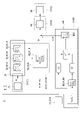
- FIG. 1 is a schematic configuration diagram schematically showing an example of a configuration of an internal combustion engine system including an exhaust gas purification system according to an embodiment of the present disclosure.
- the internal combustion engine system 1 includes an internal combustion engine 2 and an exhaust gas purification system 3 for purifying exhaust gas discharged from the internal combustion engine 2.
- the internal combustion engine 2 includes a plurality of cylinders 21 and a piston 22 housed inside each of the plurality of cylinders 21.
- the internal combustion engine 2 has a combustion chamber 23 formed between a cylinder 21 and a piston 22 housed inside the cylinder 21.
- the internal combustion engine 2 is configured to burn fuel and combustion gas in the combustion chamber 23.
- the internal combustion engine 2 comprises a diesel engine. In some other embodiments, the internal combustion engine 2 may be an engine other than a diesel engine.
- the exhaust gas purification system 3 controls the exhaust gas purification device 4 including the DOC (diesel oxidation catalyst) 41 and the DPF (diesel particulate filter) 42, and the temperature raising means 5 of the exhaust gas purification device 4, thereby causing the exhaust gas purification device 4.
- a DPF regeneration control device 6 (ECU 7) configured to perform regeneration processing (that is, recovery processing of DOC41 and forced regeneration processing of DPF 42) is provided.
- the DPF regeneration control device 6 is configured to perform a forced regeneration process of the DPF 42, that is, a control for raising the temperature of PM including the soot in the exhaust gas discharged from the internal combustion engine 2 and incinerating and removing the soot.
- the DPF regeneration control device 6 comprises an ECU 7.
- the ECU (Engine Control Unit) 7 is an electronic control unit that controls the internal combustion engine 2.
- the ECU 7 may be configured as a microcomputer including a central processing unit (CPU) including a processor, a random access memory (RAM), a read-only memory (ROM), an I / O interface, and the like.
- the DPF regeneration control device 6 (ECU 7) is adapted to input various signals from sensors provided in the internal combustion engine system 1 to a CPU or the like via an I / O interface.
- the CPU is configured to execute various controls according to a control program stored in the ROM.
- the DPF regeneration control device 6 may be implemented as one of the functions (programs and circuits) included in the ECU 7. Further, in some other embodiments, the DPF regeneration control device 6 may be configured as an electronic control unit different from the ECU 7.
- the internal combustion engine system 1 has an intake flow path 11 for sending combustion gas to be used for combustion in the combustion chamber 23 from the outside of the internal combustion engine 2 to the internal combustion engine 2, and an exhaust gas discharged from the internal combustion engine 2.
- An exhaust flow path 12 and a fuel injection device 13 for injecting unburned fuel into the inside of the internal combustion engine 2 (combustion chamber 23 in the illustrated example) are further provided.
- the intake flow path 11 is connected to the upstream side of the internal combustion engine 2
- the exhaust flow path 12 is connected to the downstream side of the internal combustion engine 2.
- Examples of the combustion gas include atmospheric pressure air, compressed air compressed by a compressor, and an air-fuel mixture containing air (compressed air) and EGR gas.
- the fuel injection device 13 is configured to inject high-pressure unburned fuel into the combustion chamber 23. In some other embodiments, the fuel injection device 13 is configured to inject high pressure unburned fuel into the vicinity of the combustion chamber 23 of the intake flow path 11.
- the fuel injection device 13 is connected to a common rail (not shown) in which high-pressure fuel is stored, and the injection timing (injection crank angle) and fuel injection amount are controlled by the DPF regeneration control device 6 (ECU 7). Has been done.
- the high-pressure fuel injected in the vicinity of the combustion chamber 23 of the combustion chamber 23 or the intake flow path 11 is confused with the fuel gas sent to the combustion chamber 23 through the intake flow path 11 and then the combustion chamber 23. Burn inside.
- the exhaust gas generated by the combustion in the combustion chamber 23 is discharged to the outside of the internal combustion engine system 1 through the exhaust flow path 12.
- the DOC 41 is arranged on the upstream side of the DPF 42 of the exhaust flow path 12.
- the DPF 42 is arranged on the downstream side of the DOC41 of the exhaust flow path 12.
- the "upstream side” means the upstream side in the flow direction of the exhaust gas flowing through the exhaust flow path 12
- the “downstream side” means the downstream side in the flow direction of the exhaust gas flowing through the exhaust gas flow path 12.
- the DOC41 has a function of oxidizing and removing unburned fuel (HC) and carbon monoxide (CO) in the exhaust gas passing through the DOC41 by accelerating the oxidation reaction by an oxidation catalyst, and the nitrogen monoxide (NO) in the exhaust gas. ) Is oxidized to generate nitrogen dioxide (NO 2 ) capable of burning and removing PM by reacting with PM collected in DPF42. Further, the DOC 41 further has a function of raising the temperature of the exhaust gas passing through the DOC 41 and raising the inlet temperature of the DPF 42 by the heat generated by the oxidation reaction of the unburned fuel contained in the exhaust gas during the forced regeneration process of the DPF 42. Have.
- the DOC 41 includes, for example, a main body having a large number of ventilation holes in a honeycomb shape and having an outer shape formed in a cylindrical shape or a rectangular parallelepiped shape, and an oxidation catalyst supported on the inner surface of the main body.
- the DPF 42 is a device having a filter that collects PM (particulate matter) containing soot (soot) in the exhaust gas discharged from the internal combustion engine 2 and removes it from the exhaust gas.
- the exhaust gas from which PM has been removed by the DPF 42 is discharged to the outside of the internal combustion engine system 1.
- the DPF 42 has, for example, a main body having a large number of ventilation holes in a honeycomb shape and having an outer shape formed in a cylindrical shape or a rectangular parallelepiped shape, and among the above-mentioned large number of ventilation holes, the inlet side and the outlet side of the ventilation holes adjacent to each other.
- the DPF 42 is configured so that the exhaust gas passes through the filter, and the PM is removed from the exhaust gas when it passes through the filter of the DPF 42.
- the DPF 42 may further contain an oxidation catalyst supported on the inner surface of the main body.
- the internal combustion engine system 1 further includes at least one of an intake throttle valve 14 installed in the intake flow path 11 and an exhaust throttle valve 15 installed in the exhaust flow path 12.
- the exhaust throttle valve 15 is arranged on the upstream side of the DOC41 of the exhaust flow path 12.
- Each of the intake throttle valve 14 and the exhaust throttle valve 15 is configured so that the opening degree thereof is controlled by the DPF regeneration control device 6 (ECU 7).
- the internal combustion engine system 1 further includes a turbocharger 16 (supercharger).
- the turbocharger 16 includes a compressor 161 arranged in the intake flow path 11, an exhaust turbine 162 arranged in the exhaust flow path 12, and a rotary shaft 163 to which the compressor 161 and the exhaust turbine 162 are attached.
- the exhaust turbine 162 is arranged on the upstream side of the exhaust throttle valve 15 and the DOC 41 of the exhaust flow path 12.
- the compressor 161 and the exhaust turbine 162 are coaxially coupled by a rotary shaft 163. When the exhaust turbine 162 is rotationally driven by the exhaust gas passing through the exhaust flow path 12, the coaxial compressor 161 is also rotationally driven.
- the combustion gas compressed by the rotational drive of the compressor 161 and having an increased density is sent to the combustion chamber 23 of the internal combustion engine 2.
- the exhaust gas flowing through the exhaust flow path 12 flows into the DOC 41 (exhaust gas purification device 4) after the exhaust turbine 162 is rotationally driven.
- the internal combustion engine system 1 may include a supercharger or an electric compressor instead of the turbocharger 16. Further, the internal combustion engine system 1 may be configured to naturally aspirate atmospheric pressure air into the combustion chamber 23 without providing a turbocharger 16 or the like.
- the internal combustion engine system 1 is an EGR device 17 configured to use a part of the exhaust gas flowing through the exhaust flow path 12 as EGR gas and return it to the upstream side of the compressor 161 of the intake flow path 11. Further prepare.
- the EGR device 17 includes an EGR pipe 171 connecting the intake flow path 11 and the exhaust flow path 12, and an EGR valve 172 arranged on the EGR pipe 171.
- EGR pipe 171 One end of the EGR pipe 171 is connected to the upstream side of the exhaust turbine 162 of the exhaust flow path 12, and the EGR pipe 171 branches from the exhaust flow path 12. Further, the EGR pipe 171 is connected to the other end of the intake flow path 11 on the upstream side of the compressor 161 and on the downstream side of the intake throttle valve 14.
- the EGR valve 172 is configured so that its opening degree is controlled by the DPF regeneration control device 6 (ECU 7). By controlling the opening degree of the EGR valve 172 to open the EGR valve 172, a part of the exhaust gas discharged from the internal combustion engine 2 is returned to the intake flow path 11 through the EGR pipe 171.
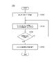
- FIG. 2 is a flow chart showing an example of a method for regenerating the exhaust gas purification device according to the embodiment of the present disclosure.
- 3 and 4 are block diagrams for explaining the function of the DPF regeneration control device according to the embodiment of the present disclosure.
- the regeneration method 100 of the exhaust gas purification device 4 takes into consideration the cetane number (actual cetane number AC) of the fuel used in the internal combustion engine 2 described above, and the DPF 42.
- the deposit amount SA for estimating the deposit amount SA of the suit collected in the above and the deposit amount SA of the suit estimated in the deposit amount estimation step S101 exceed a predetermined value (threshold value T)
- the DPF42 is increased.
- a DPF regeneration step S102 which is heated to incinerate and remove the soot, is provided.
- the DPF regeneration control device 6 (ECU 7). As shown in FIGS. 3 and 4, the DPF regeneration control device 6 (ECU 7) is configured to estimate the sedimentation amount SA of the suit in consideration of the database unit 61 and the actual cetane number AC. Section 62 and.
- the deposit amount estimation unit 62 is configured to be able to acquire necessary information from the database unit 61.
- the database unit 61 stores the information acquired by the sensors provided in the internal combustion engine system 1.
- the cetane number (actual cetane number AC) of the fuel actually used in the internal combustion engine 2 is converted into the above-mentioned DPF regeneration before the deposition amount estimation step S101. Further, the actual cetane number registration step S103 to be stored in the database unit 61 of the control device 6 (ECU 7) is provided.
- the actual cetane number AC known by the worker is connected to the I / O interface 71 (FIG. 3). (See) is performed to input to the database unit 61.
- the above-mentioned worker sets the maximum value in the guaranteed range of the cetane number guaranteed by the internal combustion engine 2 as the actual cetane number AC via the I / O interface 71. May be input to the database unit 61.
- the cetane number (estimated cetane number) estimated by the DPF regeneration control device 6 (ECU 7) or the operator is stored in the database unit 61 as the actual cetane number AC. May be good.
- the DPF regeneration control device 6 (ECU 7) may further include a cetane number estimation unit 63 (see FIG. 4) configured to estimate the cetane number actually used in the internal combustion engine 2.
- the cetane number estimation unit 63 is configured to be able to acquire necessary information from the database unit 61. Further, the cetane number estimation unit 63 estimates the estimated cetane number by a known means for estimating the cetane number. Since the estimated cetane number has an estimation error with the actual cetane number AC, it is preferable to use the known actual cetane number AC when the actual cetane number AC is known.
- the sedimentation amount SA of the suit is estimated in consideration of the actual cetane number AC stored in the database unit 61.
- the reproduction method 100 described above further includes a determination step S104 for determining whether or not the deposit amount SA of the suit estimated in the deposit amount estimation step S101 exceeds the threshold value T.
- the determination step S104 determines whether or not the deposit amount SA of the suit estimated in the deposit amount estimation step S101 exceeds the threshold value T.
- the determination unit 64 executes the determination step S104.
- the DPF regeneration control device 6 (ECU 7) further includes a determination unit 64 configured to determine whether or not the accumulated amount SA of the suit in the DPF 42 exceeds the threshold value T. ..
- the determination unit 64 is configured to be able to acquire necessary information from the database unit 61.
- the temperature of the DPF 42 is raised and the soot is incinerated and removed by controlling the temperature raising means 5 of the exhaust gas purification device 4.
- the forced regeneration executing unit 65 controls the temperature raising means 5, so that the temperature of the DPF 42 is raised and the suit is incinerated and removed.
- the DPF regeneration control device 6 (ECU 7) further includes a forced regeneration execution unit 65.
- the heating means 5 includes at least one of a fuel injection device 13, an intake throttle valve 14, an exhaust throttle valve 15, and an EGR valve 172.
- the forced regeneration execution unit 65 is at least among the injection timing (injection crank angle) and fuel injection amount of the fuel injection device 13, the opening degree of the intake throttle valve 14, the opening degree of the exhaust throttle valve 15, and the opening degree of the EGR valve 172. By controlling one, it is configured to raise the temperature of the DPF 42.
- the exhaust gas purification system 3 has a DPF 42 that collects soot (soot) in the exhaust gas discharged from the internal combustion engine 2 and a soot collected by the DPF 42.
- a DPF regeneration control device 6 configured to control the temperature of the DPF 42 to incinerate and remove the soot when the deposited amount SA exceeds a predetermined value (threshold value T) is provided.
- the DPF regeneration control device 6 includes a deposit amount estimation unit 62 configured to estimate the deposit amount SA of the suit in consideration of the cetane number (actual cetane number AC) of the fuel used in the internal combustion engine 2.
- the DPF regeneration control device 6 can suppress the estimation error by estimating the deposition amount SA of the suit in consideration of the actual cetane number AC, so that the estimation accuracy of the deposition amount SA of the suit can be suppressed. Can be improved.
- the regeneration method 100 of the exhaust gas purification device 4 is captured by the DPF 42 in consideration of the cetane number (actual cetane number AC) of the fuel used in the internal combustion engine 2.
- the sedimentation amount SA for estimating the accumulated amount SA of the collected suit and the sedimentation amount SA of the suit estimated in the deposition amount estimation step S101 exceed a predetermined value (threshold T)
- the temperature of the DPF 42 is raised.
- the DPF regeneration step S102 for burning and removing the suit is provided.
- the setane number SA of the suit is set in advance by considering the cetane number (actual cetane number AC) of the fuel used in the internal combustion engine 2.
- cetane number actual cetane number AC
- the estimation accuracy of the deposit amount SA of the suit can be improved.
- the deposition amount estimation step S101 (S105) an internal combustion engine among a plurality of estimation means 8 having different fuel cetane numbers (set cetane number SC).
- the deposition amount SA of the suit is estimated by using the estimation means 8 corresponding to the cetane number (actual cetane number AC) of the fuel used in 2.
- the deposit amount estimation unit 62 (62A) executes the deposit amount estimation step S101 (S105).
- the deposit amount estimation unit 62 (62A) corresponds to the cetane number (actual cetane number AC) of the fuel used for the internal combustion engine 2 among the plurality of estimation means 8 having different fuel cetane numbers (set cetane number SC).
- the estimation means 8 is configured to estimate the deposit amount SA of the suit.
- Each of the plurality of estimation means 8 has a first correspondence relationship information 81 indicating a correspondence relationship between the operating state of the internal combustion engine 2 and the emission amount of the suit under the set cetane number SC set individually in advance.
- the first correspondence information 81 may be any information as long as the information regarding the operating state of the internal combustion engine 2 is input information and the emission amount of the soot corresponding to the input information can be output, and the input information (operation of the internal combustion engine 2) is sufficient. Includes lists and tables, maps, functions, machine learning models, etc. that show the correspondence between state information) and output information (soot emissions).
- Correspondence-related information may be created based on the steady-state test data, or may be created based on past actual values, experimental values, numerical analysis results, etc. other than the steady-state test data.
- a plurality of estimation means 8 are stored in the database unit 61 in advance before the deposit amount estimation step S101.
- the estimation means 8 includes a soot emission map 82 that outputs a soot emission amount according to the operating state of the internal combustion engine 2 (rotational speed and load of the internal combustion engine 2).
- the rotation speed and the load of the internal combustion engine 2 are calculated based on the input signals from various sensors such as a crank sensor, a cam sensor, an accelerator sensor, and a throttle sensor (not shown). ing.
- the deposit amount estimation unit 62 uses the set cetane number SC as the actual cetane number AC stored in the database unit 61 from the plurality of suit emission maps 82 (estimation means 8) having different set cetane number SCs.
- the closest suit emission map 82 (estimating means 8) is selected (estimating means selection step).
- the deposition amount estimation unit 62 uses the selected suit emission amount map 82 (estimation means 8) to discharge the soot (accumulation) corresponding to the operating state of the internal combustion engine 2 (rotational speed and load of the internal combustion engine 2).
- the amount of change in the amount) is calculated from moment to moment, and the calculated soot emission amount is integrated to estimate the soot accumulation amount SA.
- the DPF regeneration control device 6 may use the plurality of estimation means 8 when estimating the deposition amount SA of the suit.
- the estimation means 8 of the above the estimation means 8 corresponding to the cetane number (actual cetane number AC) of the fuel used for the internal combustion engine 2 can be used.
- the DPF regeneration control device 6 can easily estimate the deposition amount SA of the suit in consideration of the actual cetane number AC by using the estimation means 8 corresponding to the actual cetane number AC.
- the DPF regeneration control device 6 can suppress the estimation error by estimating the accumulated amount SA of the suit in consideration of the actual cetane number AC, the accumulated amount SA of the suit can be estimated accurately. Further, since the DPF regeneration control device 6 can easily estimate the deposition amount SA of the suit in consideration of the actual cetane number AC by using the estimation means 8 corresponding to the actual cetane number AC, the suit in the accumulation amount estimation unit 62 It is possible to suppress the complexity of the arithmetic processing for estimating the deposited amount SA.
- the soot deposition amount SA is used by using the estimation means 8 corresponding to the preset set cetane number SC. Is estimated, and the cetane number SA of the fuel estimated by the estimation means 8 is corrected in consideration of the cetane number (actual cetane number AC) of the fuel used in the internal combustion engine 2.
- the deposit amount estimation unit 62 (62B) executes the deposit amount estimation step S101 (S105).
- the deposit amount estimation unit 62 (62B) includes a deposit amount provisional estimation unit 621 configured to estimate the deposit amount SA of the soot using the estimation means 8 corresponding to the preset set cetane number SC, and the internal combustion.
- the sedimentation amount correction unit 622 that corrects the sedimentation amount SA of the soot estimated by the sedimentation amount provisional estimation unit 621 is included.
- the estimation means 8 corresponding to the predetermined set cetane number SC is stored in the database unit 61 in advance before the deposit amount estimation step S101.
- the estimation means 8 includes a soot emission map 82 that outputs a soot emission amount according to the operating state of the internal combustion engine 2 (rotational speed and load of the internal combustion engine 2).
- the deposit amount provisional estimation unit 621 corresponds to the operating state of the internal combustion engine 2 (rotational speed and load of the internal combustion engine 2) by using the soot emission amount map 82 (estimation means 8) corresponding to the predetermined set cetane number SC.
- the soot deposition amount SA is estimated by calculating the soot discharge amount from moment to moment and integrating the calculated soot discharge amount.
- the sedimentation amount correction unit 622 uses the second correspondence information 623, which indicates the correspondence relationship between the cetane number and the sedimentation amount (emission amount) of the suit, to obtain the sedimentation amount SA of the suit estimated by the sedimentation amount provisional estimation unit 621. to correct.
- the deposit amount SA of the suit corresponding to the actual cetane number AC is estimated.
- the suit emission amount calculated by the deposit amount provisional estimation unit 621 every moment is corrected every moment using the second correspondence information 623, and the corrected suit is corrected every moment. It is also included to estimate the sedimentation amount SA of the suit by integrating the discharge amount of the suit.
- the second correspondence information 623 uses the set cetane number SC, the accumulated amount SA (emission amount) of the soot corresponding to the set cetane number SC, and the actual cetane number AC as input information, and the accumulated amount of the soot corresponding to the input information. Any information that can output SA (deposited amount (emission amount) of soot corresponding to the actual cetane number AC) is sufficient, and a list, table, map, function, or machine showing the correspondence between the above input information and the above output information is sufficient. Includes learning models and more.
- the second correspondence information 623 may be created based on the steady-state test data, or may be created based on past actual values, experimental values, numerical analysis results, etc. other than the steady-state test data.
- the DPF regeneration control device 6 uses the estimation means 8 corresponding to the set cetane number SC when estimating the sedimentation amount SA of the suit by the deposition amount provisional estimation unit 621, whereby the set cetane number is set. It is possible to estimate the sedimentation amount SA of the suit in consideration of SC.
- the DPF regeneration control device 6 takes into consideration the cetane number (actual cetane number AC) of the fuel used in the internal combustion engine 2, and corresponds to the accumulated amount SA (set cetane number) of the suit estimated by the accumulated amount provisional estimation unit 621. By correcting the accumulated amount of the suit), the estimation error can be suppressed, and the accumulated amount SA of the suit corresponding to the actual cetane number AC can be easily and accurately obtained.
- FIG. 5 is a graph showing the correspondence between the cetane number and the accumulated amount (emission amount) of the suit.
- the cetane number of the fuel is on the horizontal axis
- the accumulated amount (emission amount) of the suit is on the vertical axis.
- the solid line LA in FIG. 5 is a straight line connecting the measured values of the cetane number of the fuel and the accumulated amount of the suit plotted on FIG. 5 (linear interpolation).
- the dotted line LB in FIG. 5 represents the correspondence between the cetane number and the amount of soot deposited by an exponential function. As shown in FIG.
- the present inventors express the correspondence between the cetane number and the accumulated amount (emission amount) of the suit by an exponential function, so that the accumulated amount of the suit corresponding to the cetane number is expressed from the cetane number. It was discovered that (emission amount) can be calculated accurately.
- the deposition correction unit 622 described above uses the information 623A showing the correspondence between the cetane number represented by the exponential function and the deposition amount of the suit, as shown in FIG. It is configured to correct the soot deposition amount SA estimated by the tentative estimation unit 621.
- SA EXP (CV x AC) / EXP (CV x SC) x SA1 ...
- AC is the actual cetane number
- SC is the set cetane number
- CV is the correction value
- SA1 is the deposition amount of the suit corresponding to the set cetane number SC (estim
- the correction value CV is calculated by a correction value calculation map in which information on the operating state of the internal combustion engine 2 (rotational speed and load of the internal combustion engine 2) is used as input information and the correction value CV is used as output information.
- the correction value calculation map is created in advance based on steady-state test data, past actual values and experimental values, numerical analysis results, and the like, and is stored in the database unit 61.
- the deposit amount correction unit 622 is configured to calculate the correction value CV from the correction value calculation map.
- the deposit amount correction unit 622 corrects by using the information 623A (for example, the formula (1)) indicating the correspondence between the cetane number represented by the exponential function and the deposit amount of the suit.
- the above estimation error can be effectively suppressed.
- the sedimentation amount estimation unit 62 (62B) including such a sedimentation amount correction unit 622 can accurately estimate the sedimentation amount SA of the suit in consideration of the actual cetane number AC.
- the amount of the suit accumulated (emission amount) at the time of the low load is changed to the amount at the time of the high load. It takes time to increase the amount of soot deposited (emission). This is due to the delay time until the wall surface temperature of the cylinder 21 rises.
- the ignition delay period is prolonged, so that the accumulated amount (emission amount) of the suit remains low, but the wall surface temperature of the cylinder 21 rises over time, so that ignition is performed. The delay period is shortened, and the amount of soot deposited (emissions) increases.
- FIG. 6 is a block diagram for explaining the function of the DPF regeneration control device according to the embodiment of the present disclosure.
- the above-mentioned deposition amount estimation step S101 is not only an estimation step S105 for estimating the deposition amount SA of the suit in consideration of the actual setan value AC, but also an estimation step.
- the amount of soot deposited in the estimation step S105 based on the difference between the wall surface temperature of the cylinder 21 of the internal combustion engine 2 (actual wall surface temperature AT) and the preset wall surface temperature of the cylinder 21. It also includes a transient correction step S106 for correcting SA.
- the transient correction unit 66 executes the transient correction step S106.
- the transient correction unit 66 is based on the difference ⁇ T between the wall surface temperature (actual wall surface temperature AT) of the cylinder 21 of the internal combustion engine 2 and the preset wall surface temperature ST of the cylinder 21, and the above-mentioned deposition amount estimation unit 62 ( It is configured to correct the soot deposition amount SA estimated in 62A, 62B).
- the DPF regeneration control device 6 further includes a transient correction unit 66.
- the set wall temperature ST is the wall temperature in the steady state (stable state) at each operating point.
- the set wall temperature ST is calculated by the set wall temperature calculation map 661A which uses the information EC (rotational speed ES and load EL of the internal combustion engine 2) regarding the operating state of the internal combustion engine 2 as input information and the set wall temperature ST as output information.
- the set wall temperature calculation map 661A is created in advance based on steady test data, past actual values, experimental values, numerical analysis results, and the like, and is stored in the database unit 61.
- the transient correction unit 66 is configured to calculate the set wall temperature ST by the set wall temperature calculation map 661A.
- the transient correction unit 66 uses the third correspondence information 662 showing the correspondence between the above-mentioned difference ⁇ T and the correction amount ⁇ SA1 of the suit accumulation amount (emission amount), and the soot accumulation amount (emission amount) from the difference ⁇ T.
- Amount) correction amount ⁇ SA1 is calculated, and the calculated soot deposition amount (emission amount) correction amount ⁇ SA1 is added to the soot deposition amount SA estimated by the deposition amount estimation unit 62 (62A, 62B). , The deposit amount SA of the suit is corrected.
- the third correspondence information 662 may be any information as long as it has at least the difference ⁇ T as input information and can output the correction amount of the deposit amount (emission amount) ⁇ SA1 of the soot corresponding to the input information. Includes lists and tables, maps, functions, machine learning models, etc. that show the correspondence with the output information.
- the third correspondence information 662 is created based on past actual values, experimental values, numerical analysis results, and the like.
- the input information of the third correspondence information 662 may include not only the difference ⁇ T but also the information EC (rotational speed ES and load EL of the internal combustion engine 2) regarding the operating state of the internal combustion engine 2 and the set wall temperature ST. ..
- the transient correction unit 66 deposits based on the difference ⁇ T between the wall surface temperature (actual wall surface temperature AT) of the cylinder 21 of the internal combustion engine 2 and the preset wall surface temperature ST of the cylinder 21.
- the soot deposit amount SA estimated by the amount estimation unit 62 it is possible to obtain the soot deposit amount SA in consideration of the ignition delay change due to the wall surface temperature change during the transient operation.
- the deposit amount estimation unit 62 including such a transient correction unit 66 can accurately estimate the deposit amount SA of the suit.
- the transient correction unit 66 described above relates to the association information 661 (eg, the setting wall surface described above) associated with the speed ES of the internal combustion engine 2, the load EL of the internal combustion engine 2, and the wall surface temperature of the cylinder 21. Based on the temperature calculation map 661A), the wall surface temperature of the cylinder 21 corresponding to the actual rotation speed ES and the actual load EL of the internal combustion engine 2 is set as the set wall surface temperature ST.
- the association information 661 eg, the setting wall surface described above
- the wall surface temperature of the cylinder 21 corresponding to the actual rotation speed ES and the actual load EL of the internal combustion engine 2 is set as the set wall surface temperature ST.
- the actual rotation speed ES of the internal combustion engine 2 and the actual rotation speed ES of the internal combustion engine 2 are based on the association information 661 associated with the rotation speed ES of the internal combustion engine 2, the load EL of the internal combustion engine 2, and the wall surface temperature of the cylinder 21 prepared in advance. From the actual load EL, the wall surface temperature of the cylinder 21 corresponding to the actual rotation speed ES of the internal combustion engine 2 and the actual load EL can be easily obtained.
- the transient correction unit 66 can easily acquire the set wall temperature ST by setting the wall surface temperature of the cylinder 21 obtained from the association information 661 as the set wall temperature ST used for the correction. In this case, it is possible to suppress the complexity of the arithmetic processing in the transient correction unit 66.
- the exhaust gas purification system 3 described above further comprises a wall surface temperature acquisition device 31 configured to acquire the wall surface temperature of the cylinder 21.
- the wall surface temperature acquisition device 31 is configured to actually measure the temperature of the wall surface of the cylinder 21 (the wall surface facing the combustion chamber 23) moment by moment and output the measured wall surface temperature to the DPF regeneration control device 6 (ECU 7). Includes the temperature sensor 31A.
- the transient correction unit 66 described above uses the wall surface temperature acquired by the wall surface temperature acquisition device 31 as the actual wall surface temperature AT.
- the transient correction unit 66 has the above-mentioned accumulated amount based on the difference ⁇ T between the wall surface temperature (actual wall surface temperature AT) acquired by the wall surface temperature acquisition device 31 and the preset wall surface temperature ST of the cylinder 21. It is configured to correct the soot deposition amount SA estimated by the estimation unit 62 (62A, 62B).
- the transient correction unit 66 is estimated by the deposit amount estimation unit 62 based on the difference ⁇ T between the wall surface temperature (measured value) acquired by the wall surface temperature acquisition device 31 and the set wall surface temperature ST. Correct the deposit amount SA of the suit. If the estimated wall surface temperature ET estimated by the wall surface temperature estimation unit 67 or the like described later is used as the correction parameter in the transient correction unit 66, the amount of soot deposited due to the difference between the actual wall surface temperature and the estimated wall surface temperature ET. There is a risk that an SA estimation error will occur.
- the above estimation error can be suppressed and the correction accuracy in the transient correction unit 66 can be improved.
- the deposit amount estimation unit 62 including the transient correction unit 66 can accurately estimate the deposit amount SA of the suit.
- FIG. 7 is a block diagram for explaining the function of the DPF regeneration control device according to the embodiment of the present disclosure.
- FIG. 8 is a block diagram for explaining the function of the estimation model in one embodiment of the present disclosure.
- the DPF regeneration control device 6 (ECU 7) described above is an estimation model 9 for estimating the change amount CT of the wall surface temperature of the cylinder 21 as shown in FIGS. 7 and 8.
- Information on the operating state of the internal combustion engine 2 Using the estimation model 9 that associates the EC with the change amount CT of the wall surface temperature, the wall surface temperature (estimated wall surface temperature ET) of the cylinder 21 is estimated from the operating state of the internal combustion engine 2. It further includes a configured wall surface temperature estimation unit 67.
- the transient correction unit 66 corrects the build amount SA of the suit estimated by the deposit amount estimation unit 62 based on the difference ⁇ T between the estimated wall surface temperature ET estimated by the wall surface temperature estimation unit 67 and the set wall surface temperature ST. It is configured as follows.
- the change amount CT of the wall surface temperature of the cylinder 21 is based on the wall surface temperature T1 in the steady state (stable state) before the operating state of the internal combustion engine 2 (that is, the rotation speed and the load of the internal combustion engine 2) changes.
- the estimation model 9 is created in advance based on past actual values, experimental values, numerical analysis results, and the like before the deposition amount estimation step S101, and is stored in the database unit 61.
- the wall surface temperature estimation unit 67 can estimate the wall surface temperature of the cylinder 21 from the operating state of the internal combustion engine 2 by using the estimation model 9.
- the transient correction unit 66 corrects the suit deposit amount SA estimated by the deposit amount estimation unit 62 by using the wall surface temperature (estimated wall surface temperature ET) estimated by the wall surface temperature estimation unit 67 as the correction parameter. It is possible to obtain the deposition amount SA of the suit in consideration of the change in ignition delay during transient operation.
- the estimation model 9 described above includes a first estimation model 9A and a second estimation model 9B.
- the wall surface temperature estimation unit 67 described above is configured to reflect the change amount CT of the wall surface temperature calculated using each of the first estimation model 9A and the second estimation model 9B in the estimated wall surface temperature ET.
- the first estimation model 9A is a first heat transfer amount which is a heat transfer amount between the wall surface of the cylinder 21 and the combustion chamber 23 facing the wall surface, and is a first heat transfer amount corresponding to the rotation speed of the internal combustion engine 2. , It is associated with the change amount CT (rise amount CT1) of the wall surface temperature.
- the first estimation model 9A is configured to be able to output at least the rotation speed of the internal combustion engine 2 as input information and the change amount CT (rise amount CT1) of the wall surface temperature as output information.
- the second estimation model 9B is a second heat transfer amount which is a heat transfer amount between the wall surface of the cylinder 21 and the cooling medium for cooling the cylinder 21, and is the rotation speed of the internal combustion engine 2 and the fuel injection amount (internal combustion engine).
- the second heat transfer amount corresponding to each of the loads of 2) is associated with the change amount CT (decrease amount CT2) of the wall surface temperature.
- the second estimation model 9B is configured to be capable of outputting at least the rotation speed of the internal combustion engine 2 and the fuel injection amount (load of the internal combustion engine 2) as input information, and the change amount CT of the wall surface temperature (decrease amount CT2) as output information. Has been done.
- the wall surface temperature estimation unit 67 obtains the wall temperature change CT (rise CT1) obtained by the first estimation model 9A and the second estimation model 9B for the wall temperature T1 in the reference steady state (stable state).
- the temperature calculated by adding the change amount CT (decrease amount CT2) of the wall surface temperature is defined as the estimated wall surface temperature ET.
- the wall surface temperature estimation unit 67 uses the first estimation model 9A to measure the change amount CT (rise amount CT1) of the wall surface temperature that changes due to heat input to the wall surface of the cylinder 21 every moment. Can be calculated. Further, by using the second estimation model 9B, the wall surface temperature estimation unit 67 calculates the change amount CT (decrease amount CT2) of the wall surface temperature that changes due to the heat being discharged from the wall surface of the cylinder 21 every moment. be able to.
- the wall surface temperature estimation unit 67 is estimated by the wall surface temperature estimation unit 67 by reflecting the change amount CT of the wall surface temperature calculated using each of the first estimation model 9A and the second estimation model 9B in the estimated wall surface temperature ET.
- the estimation accuracy of the wall surface temperature (estimated wall surface temperature ET) can be improved, and the difference between the estimated wall surface temperature ET and the measured value can be suppressed.
- the correction accuracy in the transient correction unit 66 can be improved, so that the deposit amount estimation unit 62 including the transient correction unit 66 can accurately estimate the deposit amount SA of the suit. ..
- the present disclosure is not limited to the above-mentioned embodiment, and includes a form in which the above-mentioned embodiment is modified and a form in which these forms are appropriately combined.
- the exhaust gas purification system (3) is An exhaust gas purification system (3) for purifying exhaust gas discharged from an internal combustion engine (2).
- the DPF (42) that collects the soot in the exhaust gas and Control for incinerating and removing the soot by raising the temperature of the DPF (42) when the deposited amount (SA) of the soot collected in the DPF (42) exceeds a predetermined value (threshold value T).
- a DPF regeneration control device (6) configured to perform the above-mentioned
- the DPF regeneration control device (6) is It includes a deposit amount estimation unit (62) configured to estimate the deposit amount (SA) of the suit in consideration of the cetane number (actual cetane number AC) of the fuel used in the internal combustion engine (2). ..
- the DPF regeneration control device can suppress the estimation error by estimating the accumulated amount of the suit in consideration of the actual cetane number, so that the estimation accuracy of the accumulated amount of the suit is improved. can.
- the exhaust gas purification system (3) described in 1) above is used.
- the DPF regeneration control device can estimate the accumulated amount of the soot by using the internal combustion engine among the plurality of estimation means.
- An estimation means corresponding to the cetane number (actual cetane number) of the fuel used in the engine can be used.
- the DPF regeneration control device can easily estimate the amount of the soot deposited in consideration of the actual cetane number by using the estimation means corresponding to the actual cetane number. Since the DPF regeneration control device can suppress the estimation error by estimating the accumulated amount of the suit in consideration of the actual cetane number, the accumulated amount of the suit can be estimated accurately.
- the DPF regeneration control device can easily estimate the amount of soot deposited in consideration of the actual cetane number by using the estimation means corresponding to the actual cetane number, the amount of soot deposited in the estimation unit can be estimated. It is possible to suppress the complexity of arithmetic processing.
- the deposit estimation unit (62) A deposit amount provisional estimation unit (621) configured to estimate the deposit amount (SA) of the suit using an estimation means (8) corresponding to a preset set cetane number (SC). In consideration of the cetane number (actual cetane number AC) of the fuel used in the internal combustion engine (2), the deposition amount (SA) estimated by the deposition amount provisional estimation unit (621) is corrected. Includes an amount correction unit (622).
- the DPF regeneration control device considers the set cetane number by using an estimation means corresponding to the set cetane number when estimating the sedimentation amount of the suit by the sedimentation amount provisional estimation unit.
- the amount of soot deposited can be estimated.
- the DPF regeneration control device considers the cetane number (actual cetane number) of the fuel used in the internal combustion engine, and considers the accumulated amount of the suit estimated by the tentative estimation unit of the accumulated amount (the accumulated amount of the suit corresponding to the set cetane number). ) Can be suppressed, and the amount of soot deposited corresponding to the actual cetane number can be easily and accurately obtained.
- the exhaust gas purification system (3) described in 3) above is used.
- the deposit correction unit (622) The information indicating the correspondence between the cetane number expressed by the exponential function and the deposition amount of the suit is used to correct the deposition amount (SA) of the suit estimated by the sedimentation amount provisional estimation unit (621). It was configured in.
- the present inventors have discovered that by expressing the correspondence between the cetane number and the accumulated amount of soot by an exponential function, the accumulated amount of soot corresponding to the cetane number can be accurately obtained from the cetane number.
- the deposition amount correction unit effectively suppresses the above estimation error by correcting using the information indicating the correspondence between the cetane number expressed by the exponential function and the accumulation amount of the suit. can.
- the sedimentation amount estimation unit including such a sedimentation amount correction unit can accurately estimate the sedimentation amount of the suit in consideration of the actual cetane number.
- the DPF regeneration control device (6) is The accumulated amount is based on the difference ( ⁇ T) between the wall surface temperature (actual wall surface temperature AT) of the cylinder (21) of the internal combustion engine (2) and the set wall surface temperature (ST) of the cylinder (21) set in advance. It further includes a transient correction unit (66) that corrects the deposition amount (SA) of the suit estimated by the estimation unit (62).
- the transient correction unit is the deposition of the suit estimated by the deposition amount estimation unit based on the difference between the wall surface temperature of the cylinder of the internal combustion engine and the set wall temperature of the preset cylinder. By correcting the amount, it is possible to obtain the amount of soot deposited in consideration of the change in ignition delay due to the change in wall surface temperature during transient operation.
- the sedimentation amount estimation unit including such a transient correction unit can accurately estimate the sedimentation amount of the suit.
- the exhaust gas purification system (3) described in 5) above is used.
- the transient correction unit (66) Based on the association information associated with the rotation speed of the internal combustion engine (2), the load of the internal combustion engine (2), and the wall surface temperature of the cylinder (21), the actual rotation speed and the actual load of the internal combustion engine (2) are calculated.
- the wall surface temperature of the corresponding cylinder (21) is defined as the set wall surface temperature (ST).
- the internal combustion engine is based on the actual rotation speed and the actual load of the internal combustion engine based on the association information associated with the rotation speed of the internal combustion engine, the load of the internal combustion engine, and the wall surface temperature of the cylinder prepared in advance.
- the wall surface temperature of the cylinder corresponding to the actual rotation speed and the actual load can be easily obtained.
- the transient correction unit can easily acquire the set wall temperature by setting the wall surface temperature of the cylinder obtained from the above-mentioned association information as the set wall temperature used for the correction. In this case, it is possible to suppress the complexity of the arithmetic processing in the transient correction unit.
- the exhaust gas purification system (3) according to the above 5) or 6).
- a wall surface temperature acquisition device (31) configured to acquire the wall surface temperature of the cylinder (21) is provided.
- the transient correction unit (66) It was estimated by the deposit amount estimation unit (62) based on the difference ( ⁇ T) between the wall surface temperature (actual wall surface temperature AT) acquired by the wall surface temperature acquisition device (31) and the set wall surface temperature (ST). It was configured to compensate for the deposit (SA) of the suit.
- the transient correction unit is the deposition of the suit estimated by the deposition amount estimation unit based on the difference between the wall surface temperature (measured value) acquired by the wall surface temperature acquisition device and the set wall surface temperature. Correct the amount. If the estimated wall surface temperature estimated by the wall surface temperature estimation unit or the like is used as the correction parameter in the transient correction unit, there is a risk that an error in estimating the amount of soot deposited due to the difference between the actual wall surface temperature and the estimated wall surface temperature will occur. There is. By using the wall surface temperature (actual measurement value) acquired by the wall surface temperature acquisition device as the correction parameter in the transient correction unit, the above estimation error can be suppressed and the correction accuracy in the transient correction unit can be improved.
- the sedimentation amount estimation unit including the part can accurately estimate the sedimentation amount of the suit.
- the DPF regeneration control device (6) is It is an estimation model (9) for estimating the change amount (CT) of the wall surface temperature of the cylinder (21), and is an estimation relating the information on the operating state of the internal combustion engine and the change amount (CT) of the wall surface temperature. Further including a wall surface temperature estimation unit (67) configured to estimate the wall surface temperature of the cylinder (21) from the operating state of the internal combustion engine (2) using the model (9). The transient correction unit (66) estimates the deposition amount based on the difference ( ⁇ T) between the estimated wall surface temperature (ET) estimated by the wall surface temperature estimation unit (67) and the set wall surface temperature (ST). It was configured to correct the deposition amount (SA) of the suit estimated in part (62).
- the wall surface temperature estimation unit can estimate the wall surface temperature of the cylinder from the operating state of the internal combustion engine using the estimation model.
- the transient correction unit corrects the buildup amount of the suit estimated by the deposition amount estimation unit and considers the change in ignition delay during transient operation. It is possible to determine the amount of accumulated soot.
- the estimation model (9) is The first heat transfer amount, which is the heat transfer amount between the wall surface of the cylinder (21) and the combustion chamber (23) facing the wall surface, is the first heat transfer amount corresponding to the rotation speed of the internal combustion engine, and the said.
- the first estimation model (9A) that correlates with the amount of change in wall surface temperature (CT)
- a second heat transfer amount which is a heat transfer amount between the wall surface of the cylinder (21) and a cooling medium for cooling the cylinder (21), which is the rotation speed of the internal combustion engine (2) and the injection amount of the fuel.
- a second estimation model (9B) that associates the corresponding second heat transfer amount with the change amount (CT) of the wall surface temperature is included.
- the wall surface temperature estimation unit (67) calculates the amount of change (CT) of the wall surface temperature using each of the first estimation model (9A) and the second estimation model (9B) to obtain the estimated wall temperature (CT). It was configured to reflect in ET).
- the wall surface temperature estimation unit calculates the amount of change in wall surface temperature (increase amount CT1) that changes due to heat input to the wall surface of the cylinder by using the first estimation model. can do. Further, by using the second estimation model, the wall surface temperature estimation unit can calculate the amount of change in wall surface temperature (decrease amount CT2) that changes due to heat being discharged from the wall surface of the cylinder every moment.
- the wall surface temperature estimation unit reflects the amount of change in the wall surface temperature calculated using each of the first estimation model and the second estimation model in the estimated wall surface temperature, so that the estimated wall surface temperature estimated by the wall surface temperature estimation unit can be used.
- the estimation accuracy can be improved, and the difference between the estimated wall temperature and the measured value can be suppressed.
- the correction accuracy in the transient correction unit can be improved, so that the deposition amount estimation unit including the transient correction unit can accurately estimate the deposition amount of the suit.
- An exhaust gas purification device for purifying exhaust gas discharged from an internal combustion engine which is a method for regenerating an exhaust gas purification device including a DPF (diesel particulate filter) that collects soot (soot) in the exhaust gas.
- the DPF regeneration step comprises raising the temperature of the DPF and incinerating and removing the soot when the accumulated amount of the soot estimated in the deposition amount estimation step exceeds a predetermined value.
- the preset cetane number is calculated by estimating the accumulated amount of the suit in consideration of the cetane number (actual cetane number) of the fuel used in the internal combustion engine. Compared with the case of estimating the accumulated amount of soot in consideration, it is possible to suppress the estimation error of the accumulated amount of soot due to the difference between the actual cetane number and the set cetane number. By suppressing the above estimation error in the estimation step in this way, the estimation accuracy of the accumulated amount of the suit can be improved. By improving the estimation accuracy of the accumulated amount of the suit in the estimation step, it is possible to suppress the implementation of the unnecessary incineration removal treatment (DPF regeneration step) of the suit.
- DPF regeneration step the unnecessary incineration removal treatment
Landscapes
- Engineering & Computer Science (AREA)
- Chemical & Material Sciences (AREA)
- Combustion & Propulsion (AREA)
- Mechanical Engineering (AREA)
- General Engineering & Computer Science (AREA)
- Processes For Solid Components From Exhaust (AREA)
- Filtering Of Dispersed Particles In Gases (AREA)
Abstract
内燃機関から排出される排ガスを浄化するための排ガス浄化システムであって、排ガス中のスート(煤)を捕集するDPF(ディーゼルパティキュレートフィルタ)と、DPFに捕集されたスートの堆積量が所定値を超えたときに、DPFを昇温してスートを焼却除去するための制御を行うように構成されたDPF再生制御装置と、を備え、DPF再生制御装置は、内燃機関に使用される燃料のセタン価を考慮して、スートの堆積量を推定するように構成された堆積量推定部を含む。
Description
本開示は、内燃機関から排出される排ガスを浄化するための排ガス浄化システムおよび排ガス浄化装置の再生方法に関する。
本願は、2020年10月29日に日本国特許庁に出願された特願2020-181474号に基づき優先権を主張し、その内容をここに援用する。
本願は、2020年10月29日に日本国特許庁に出願された特願2020-181474号に基づき優先権を主張し、その内容をここに援用する。
内燃機関から排出される排ガス中のスート(煤)を含むPM(粒子状物質)を捕集除去するため、内燃機関の排気流路にDPF(ディーゼルパティキュレートフィルタ)が配置されることがある。DPFにより捕集されたPMは、所定量に達するか又は一定時間毎に強制再生によって除去される。DPFの強制再生には、自動再生および手動再生が含まれる。
強制再生を実施する適切なタイミングを把握するためには、DPFにおけるPMの捕集量を精度よく推定する必要がある。PMの捕集量(スートの堆積量)は、ECU(制御装置)において内燃機関の運転状況に応じた時々刻々の堆積量変化量を演算することにより推定される。特許文献1には、内燃機関の運転状態(内燃機関の回転数および燃料噴射量)に応じてPMの排出量を算出するPM排出量マップを用いて、PMの排出量および堆積量を推定することが開示されている。
一般的に、スートの堆積量を推定するためのマップ(例えば、特許文献1のPM排出量マップ)は、内燃機関の運転状態(内燃機関の回転数および燃料噴射量)を一定にした定常試験を実施することにより得られた定常試験データを基に作成されている。ところで、市場に流通する燃料は、燃焼の性状や特性が一様ではなく、製造メーカや地域などにより変動することがあり、燃料の着火性を示す燃料のセタン価も変動することがある。
仮に内燃機関に実際に供給される燃料のセタン価が、定常試験に用いた燃料のセタン価よりも大きい場合には、燃料が気筒内に噴射されてから着火に至るまでの期間である着火遅れ期間が短縮される。着火遅れ期間が短縮されると、着火までに燃料と空気が十分に混合できないことがあり、内燃機関の運転条件によっては、スートの排出量が増加することがある。この場合には、ECUにおいて推定されたスートの推定堆積量よりも、DPFに実際に堆積しているスートの堆積量が多くなり(過堆積)、内燃機関の燃費悪化や強制再生時の過昇温によるDPF破損の原因になる虞がある。
また、上述した過堆積を回避するために、市場に流通する燃料の中で最もセタン価の大きい燃料を用いた定常試験を実施し、スートの堆積量を推定するためのマップを作成した場合には、上述した過堆積を抑制できる。この場合には、スートの堆積量が過大に評価されるため、強制再生の頻度が多くなり、内燃機関の燃費悪化の原因になる虞がある。また、強制再生の頻度が多くなると、強制再生時の燃料によるエンジンオイルの希釈が進むため、エンジンオイルの交換頻度が増大する虞がある。
上述した事情に鑑みて、本開示の少なくとも一実施形態の目的は、スートの堆積量の推定精度を向上できる排ガス浄化システムおよび排ガス浄化装置の再生方法を提供することにある。
本開示の一実施形態にかかる排ガス浄化システムは、
内燃機関から排出される排ガスを浄化するための排ガス浄化システムであって、
前記排ガス中のスート(煤)を捕集するDPF(ディーゼルパティキュレートフィルタ)と、
前記DPFに捕集された前記スートの堆積量が所定値を超えたときに、前記DPFを昇温して前記スートを焼却除去するための制御を行うように構成されたDPF再生制御装置と、を備え、
前記DPF再生制御装置は、
前記内燃機関に使用される燃料のセタン価を考慮して、前記スートの堆積量を推定するように構成された堆積量推定部を含む。
内燃機関から排出される排ガスを浄化するための排ガス浄化システムであって、
前記排ガス中のスート(煤)を捕集するDPF(ディーゼルパティキュレートフィルタ)と、
前記DPFに捕集された前記スートの堆積量が所定値を超えたときに、前記DPFを昇温して前記スートを焼却除去するための制御を行うように構成されたDPF再生制御装置と、を備え、
前記DPF再生制御装置は、
前記内燃機関に使用される燃料のセタン価を考慮して、前記スートの堆積量を推定するように構成された堆積量推定部を含む。
本開示の一実施形態にかかる排ガス浄化装置の再生方法は、
内燃機関から排出される排ガスを浄化するための排ガス浄化装置であって、前記排ガス中のスート(煤)を捕集するDPF(ディーゼルパティキュレートフィルタ)を含む排ガス浄化装置の再生方法であって、
前記内燃機関に使用される燃料のセタン価を考慮して、前記DPFに捕集された前記スートの堆積量を推定する堆積量推定ステップと、
前記堆積量推定ステップで推定される前記スートの堆積量が所定値を超えたときに、前記DPFを昇温して前記スートを焼却除去するDPF再生ステップと、を備える。
内燃機関から排出される排ガスを浄化するための排ガス浄化装置であって、前記排ガス中のスート(煤)を捕集するDPF(ディーゼルパティキュレートフィルタ)を含む排ガス浄化装置の再生方法であって、
前記内燃機関に使用される燃料のセタン価を考慮して、前記DPFに捕集された前記スートの堆積量を推定する堆積量推定ステップと、
前記堆積量推定ステップで推定される前記スートの堆積量が所定値を超えたときに、前記DPFを昇温して前記スートを焼却除去するDPF再生ステップと、を備える。
本開示の少なくとも一実施形態によれば、スートの堆積量の推定精度を向上できる排ガス浄化システムおよび排ガス浄化装置の再生方法が提供される。
以下、添付図面を参照して本開示の幾つかの実施形態について説明する。ただし、実施形態として記載されている又は図面に示されている構成部品の寸法、材質、形状、その相対的配置等は、本開示の範囲をこれに限定する趣旨ではなく、単なる説明例にすぎない。
例えば、「ある方向に」、「ある方向に沿って」、「平行」、「直交」、「中心」、「同心」或いは「同軸」等の相対的或いは絶対的な配置を表す表現は、厳密にそのような配置を表すのみならず、公差、若しくは、同じ機能が得られる程度の角度や距離をもって相対的に変位している状態も表すものとする。
例えば、「同一」、「等しい」及び「均質」等の物事が等しい状態であることを表す表現は、厳密に等しい状態を表すのみならず、公差、若しくは、同じ機能が得られる程度の差が存在している状態も表すものとする。
例えば、四角形状や円筒形状等の形状を表す表現は、幾何学的に厳密な意味での四角形状や円筒形状等の形状を表すのみならず、同じ効果が得られる範囲で、凹凸部や面取り部等を含む形状も表すものとする。
一方、一の構成要素を「備える」、「含む」、又は、「有する」という表現は、他の構成要素の存在を除外する排他的な表現ではない。
なお、同様の構成については同じ符号を付し説明を省略することがある。
例えば、「ある方向に」、「ある方向に沿って」、「平行」、「直交」、「中心」、「同心」或いは「同軸」等の相対的或いは絶対的な配置を表す表現は、厳密にそのような配置を表すのみならず、公差、若しくは、同じ機能が得られる程度の角度や距離をもって相対的に変位している状態も表すものとする。
例えば、「同一」、「等しい」及び「均質」等の物事が等しい状態であることを表す表現は、厳密に等しい状態を表すのみならず、公差、若しくは、同じ機能が得られる程度の差が存在している状態も表すものとする。
例えば、四角形状や円筒形状等の形状を表す表現は、幾何学的に厳密な意味での四角形状や円筒形状等の形状を表すのみならず、同じ効果が得られる範囲で、凹凸部や面取り部等を含む形状も表すものとする。
一方、一の構成要素を「備える」、「含む」、又は、「有する」という表現は、他の構成要素の存在を除外する排他的な表現ではない。
なお、同様の構成については同じ符号を付し説明を省略することがある。
(内燃機関システム)
図1は、本開示の一実施形態にかかる排ガス浄化システムを備える内燃機関システムの構成の一例を概略的に示す概略構成図である。図1に示されるように、内燃機関システム1は、内燃機関2と、内燃機関2から排出される排ガスを浄化するための排ガス浄化システム3と、を備える。
図1は、本開示の一実施形態にかかる排ガス浄化システムを備える内燃機関システムの構成の一例を概略的に示す概略構成図である。図1に示されるように、内燃機関システム1は、内燃機関2と、内燃機関2から排出される排ガスを浄化するための排ガス浄化システム3と、を備える。
内燃機関2は、複数の気筒21と、複数の気筒21の夫々の内部に収容されるピストン22と、を含む。内燃機関2は、気筒21と該気筒21の内部に収容されたピストン22との間に形成された燃焼室23を有する。内燃機関2は、燃焼室23において燃料および燃焼用気体を燃焼させるように構成されている。図示される実施形態では、内燃機関2は、ディーゼルエンジンからなる。他の幾つかの実施形態では、内燃機関2は、ディーゼルエンジン以外のエンジンであってもよい。
排ガス浄化システム3は、DOC(ディーゼル酸化触媒)41およびDPF(ディーゼルパティキュレートフィルタ)42を含む排ガス浄化装置4と、排ガス浄化装置4の昇温手段5を制御することにより、排ガス浄化装置4の再生処理(すなわち、DOC41の回復処理およびDPF42の強制再生処理)を行うように構成されたDPF再生制御装置6(ECU7)と、を備える。DPF再生制御装置6は、DPF42の強制再生処理、すなわち内燃機関2から排出された排ガス中のスートを含むPMを昇温してスートを焼却除去するための制御を行うように構成されている。
図1に示される実施形態では、DPF再生制御装置6は、ECU7からなる。ECU(Engine Control Unit)7は、内燃機関2をコントロールする電子制御ユニットである。例えば、ECU7は、プロセッサを含む中央処理装置(CPU)、ランダムアクセスメモリ(RAM)、リードオンリメモリ(ROM)、及びI/Oインターフェイスなどからなるマイクロコンピュータとして構成されてもよい。
DPF再生制御装置6(ECU7)は、内燃機関システム1に設けられたセンサ類からの各種信号が、I/Oインターフェイスを介してCPUなどに入力されるようになっている。CPUでは、ROMに記憶されている制御プログラムに従って、各種制御を実行するように構成されている。なお、他の幾つかの実施形態では、DPF再生制御装置6は、ECU7の備える機能(プログラムや回路)の一つとして実装されていてもよい。また、他の幾つかの実施形態では、DPF再生制御装置6は、ECU7とは異なる電子制御ユニットとして構成されていてもよい。
内燃機関システム1は、燃焼室23における燃焼に供される燃焼用気体を内燃機関2の外部から内燃機関2に送るための吸気流路11と、内燃機関2から排出された排ガスを送るための排気流路12と、内燃機関2の内部(図示例では、燃焼室23)に未燃燃料を噴射するための燃料噴射装置13と、をさらに備える。吸気流路11は、内燃機関2の上流側に接続され、排気流路12は、内燃機関2の下流側に接続されている。燃焼用気体としては、例えば、大気圧の空気や圧縮機に圧縮された圧縮空気、空気(圧縮空気)とEGRガスを含む混合気などが挙げられる。
図示される実施形態では、燃料噴射装置13は、燃焼室23に高圧の未燃燃料を噴射するように構成されている。他の幾つかの実施形態では、燃料噴射装置13は、吸気流路11の燃焼室23近傍に高圧の未燃燃料を噴射するように構成されている。燃料噴射装置13は、高圧燃料が蓄圧された不図示のコモンレールに接続され、且つDPF再生制御装置6(ECU7)により、その噴射タイミング(噴射クランク角)および燃料噴射量が制御されるように構成されている。
通常運転時に行われるメイン噴射において、燃焼室23又は吸気流路11の燃焼室23近傍に噴射された高圧燃料は、吸気流路11を通じて燃焼室23に送られる燃料用気体と混同後に燃焼室23内で燃焼する。燃焼室23における燃焼により生じた排ガスは、排気流路12を通じて内燃機関システム1の外部に排出される。
(排ガス浄化装置)
DOC41は、排気流路12のDPF42よりも上流側に配置される。DPF42は、排気流路12のDOC41よりも下流側に配置される。ここで、「上流側」は、排気流路12を流れる排ガスの流れ方向における上流側を意味しており、「下流側」は、排気流路12を流れる排ガスの流れ方向における下流側を意味している。
DOC41は、排気流路12のDPF42よりも上流側に配置される。DPF42は、排気流路12のDOC41よりも下流側に配置される。ここで、「上流側」は、排気流路12を流れる排ガスの流れ方向における上流側を意味しており、「下流側」は、排気流路12を流れる排ガスの流れ方向における下流側を意味している。
DOC41は、酸化触媒により酸化反応を促進させることで、DOC41を通過する排ガス中の未燃燃料(HC)や一酸化炭素(CO)を酸化除去する機能、および上記排ガス中の一酸化窒素(NO)を酸化して、DPF42に捕集されたPMとの反応によりPMを燃焼除去できる二酸化窒素(NO2)を生成する機能を有する装置である。また、DOC41は、DPF42の強制再生処理時において、排ガス中に含まれる未燃燃料の酸化反応により生じる熱によって、DOC41を通過する排ガスを昇温し、DPF42の入口温度を昇温する機能をさらに有する。DOC41は、例えば、ハニカム状に多数の通気孔を有し、且つ外形が円筒形状又は直方体状に形成された本体と、該本体の内面に担持された酸化触媒と、を含む。
DOC41を通過した排ガスがDPF42に流入する。DPF42は、内燃機関2から排出された排ガス中のスート(煤)を含むPM(粒子状物質)を捕集し、排ガスから除去するフィルタを有する装置である。DPF42によりPMが除去された排ガスは、内燃機関システム1の外部に排出される。DPF42は、例えば、ハニカム状に多数の通気孔を有し、且つ外形が円筒形状又は直方体状に形成された本体と、上記多数の通気孔のうち、互いに隣接する通気孔の入口側と出口側とを交互に閉じるフィルタ(ろ過壁)と、を含む。このため、DPF42は、排ガスがフィルタを通過するように構成されており、排ガスは、DPF42のフィルタを通過する際にPMが除去される。なお、DPF42は、上記本体の内面に担持された酸化触媒をさらに含んでもよい。
内燃機関システム1は、吸気流路11に設置される吸気スロットルバルブ14、又は排気流路12に設置される排気スロットルバルブ15の少なくとも一方をさらに備える。図示される実施形態では、排気スロットルバルブ15は、排気流路12のDOC41よりも上流側に配置されている。吸気スロットルバルブ14および排気スロットルバルブ15の夫々は、DPF再生制御装置6(ECU7)により、その開度が制御されるように構成されている。
図示される実施形態では、内燃機関システム1は、ターボチャージャ16(過給機)をさらに備える。ターボチャージャ16は、吸気流路11に配置されるコンプレッサ161と、排気流路12に配置される排気タービン162と、コンプレッサ161および排気タービン162の夫々が取り付けられた回転シャフト163と、を含む。排気タービン162は、排気流路12の排気スロットルバルブ15およびDOC41よりも上流側に配置されている。コンプレッサ161および排気タービン162は、回転シャフト163により同軸で結合されている。排気流路12を通過する排ガスにより排気タービン162が回転駆動されると、同軸上のコンプレッサ161も回転駆動される。コンプレッサ161の回転駆動により圧縮されて密度が高められた燃焼用気体は、内燃機関2の燃焼室23に送り込まれる。排気流路12を流れる排ガスは、排気タービン162を回転駆動させた後に、DOC41(排ガス浄化装置4)に流入するようになっている。
他の幾つかの実施形態では、内燃機関システム1は、ターボチャージャ16の代わりに、スーパーチャージャや電動コンプレッサを備えていてもよい。また、内燃機関システム1は、ターボチャージャ16などを備えずに、大気圧の空気を燃焼室23に自然吸気するように構成されていてもよい。
図示される実施形態では、内燃機関システム1は、排気流路12を流れる排ガスの一部をEGRガスとして、吸気流路11のコンプレッサ161よりも上流側に還流させるように構成されたEGR装置17をさらに備える。EGR装置17は、吸気流路11と排気流路12とを繋ぐEGR管171と、EGR管171上に配置されたEGRバルブ172と、を含む。
EGR管171は、排気流路12の排気タービン162よりも上流側に一方側の端部が接続され、排気流路12からEGR管171が分岐している。また、EGR管171は、吸気流路11のコンプレッサ161よりも上流側、且つ吸気スロットルバルブ14よりも下流側に他方側の端部が接続されている。EGRバルブ172は、DPF再生制御装置6(ECU7)により、その開度が制御されるように構成されている。EGRバルブ172の開度を制御してEGRバルブ172を開くことで、内燃機関2から排出された排ガスの一部が、EGR管171を通じて吸気流路11に還流するようになっている。
(DPFの強制再生)
上述したように、DPF42を通過する際に排ガス中に含まれるスート(煤)を含むPMがDPF42により捕集される。DPF42により捕集されたPMは、排ガス浄化装置4に流入する排ガスが高温の場合には、高温の排ガスにより燃焼し、自然に除去される(自然再生)。自然再生により除去できないPMは、DPF42のフィルタに蓄積していく。このため、DPF42のフィルタに蓄積するPMを強制的に燃焼させて、フィルタを再生させる強制再生処理を適切なタイミングで実施する必要がある。
上述したように、DPF42を通過する際に排ガス中に含まれるスート(煤)を含むPMがDPF42により捕集される。DPF42により捕集されたPMは、排ガス浄化装置4に流入する排ガスが高温の場合には、高温の排ガスにより燃焼し、自然に除去される(自然再生)。自然再生により除去できないPMは、DPF42のフィルタに蓄積していく。このため、DPF42のフィルタに蓄積するPMを強制的に燃焼させて、フィルタを再生させる強制再生処理を適切なタイミングで実施する必要がある。
図2は、本開示の一実施形態にかかる排ガス浄化装置の再生方法の一例を示すフロー図である。図3および図4の夫々は、本開示の一実施形態におけるDPF再生制御装置の機能を説明するためのブロック図である。
幾つかの実施形態にかかる排ガス浄化装置4の再生方法100は、図2に示されるように、上述した内燃機関2に使用される燃料のセタン価(実セタン価AC)を考慮して、DPF42に捕集されたスートの堆積量SAを推定する堆積量推定ステップS101と、堆積量推定ステップS101で推定されるスートの堆積量SAが所定値(閾値T)を超えたときに、DPF42を昇温してスートを焼却除去するDPF再生ステップS102と、を備える。
幾つかの実施形態にかかる排ガス浄化装置4の再生方法100は、図2に示されるように、上述した内燃機関2に使用される燃料のセタン価(実セタン価AC)を考慮して、DPF42に捕集されたスートの堆積量SAを推定する堆積量推定ステップS101と、堆積量推定ステップS101で推定されるスートの堆積量SAが所定値(閾値T)を超えたときに、DPF42を昇温してスートを焼却除去するDPF再生ステップS102と、を備える。
再生方法100における幾つかのステップは、DPF再生制御装置6(ECU7)により行われてもよい。DPF再生制御装置6(ECU7)は、図3および図4に示されるように、データベース部61と、実セタン価ACを考慮してスートの堆積量SAを推定するように構成された堆積量推定部62と、を含む。堆積量推定部62は、必要な情報をデータベース部61から取得可能に構成されている。データベース部61には、内燃機関システム1に設けられたセンサ類が取得した情報が記憶される。
図2に示される実施形態では、上述した再生方法100は、堆積量推定ステップS101よりも前に、内燃機関2に実際に使用される燃料のセタン価(実セタン価AC)を上述したDPF再生制御装置6(ECU7)のデータベース部61に記憶させる実セタン価登録ステップS103をさらに備える。
或る実施形態では、実セタン価登録ステップS103において、作業者(例えば、内燃機関システム1を搭載した車両販売元のセールスマン)が既知の実セタン価ACを、I/Oインターフェイス71(図3参照)を介してデータベース部61に入力することが行われる。実セタン価ACが不明である場合には、上記作業者は、内燃機関2が保証しているセタン価の保証範囲のうちの最大値を、実セタン価ACとして、I/Oインターフェイス71を介してデータベース部61に入力してもよい。
或る実施形態では、実セタン価登録ステップS103において、DPF再生制御装置6(ECU7)又は作業者が推定したセタン価(推定セタン価)を、実セタン価ACとして、データベース部61に記憶させてもよい。DPF再生制御装置6(ECU7)は、内燃機関2に実際に使用されるセタン価を推定するように構成されたセタン価推定部63(図4参照)をさらに備えていてもよい。セタン価推定部63は、必要な情報をデータベース部61から取得可能に構成されている。また、セタン価推定部63は、公知のセタン価の推定手段により推定セタン価を推定するようになっている。なお、推定セタン価は、実セタン価ACとの間に推定誤差が内在するため、実セタン価ACが既知である場合には、既知の実セタン価ACを用いる方が好ましい。
詳細は後述するが、堆積量推定ステップS101では、データベース部61に記憶された実セタン価ACを考慮して、スートの堆積量SAが推定される。図2に示される実施形態では、上述した再生方法100は、堆積量推定ステップS101で推定されたスートの堆積量SAが閾値Tを超えたか否かを判定する判定ステップS104をさらに備える。判定ステップS104において、スートの堆積量SAが閾値Tを超えたと判定された場合(S104で「YES」の場合)には、上述したDPF再生ステップS102が行われる。判定ステップS104において、スートの堆積量SAが閾値T以下の場合には(S104で「NO」の場合)には、堆積量推定ステップS101および判定ステップS104が繰り返される。
図3、図4に示される実施形態では、判定部64が判定ステップS104を実行する。DPF再生制御装置6(ECU7)は、図3および図4に示されるように、DPF42におけるスートの堆積量SAが閾値Tを超えたか否かを判定するように構成された判定部64をさらに含む。判定部64は、必要な情報をデータベース部61から取得可能に構成されている。
DPF再生ステップS102では、排ガス浄化装置4の昇温手段5を制御することにより、DPF42を昇温してスートを焼却除去することが行われる。図3、図4に示される実施形態では、強制再生実行部65が昇温手段5を制御することにより、DPF42が昇温されてスートが焼却除去される。DPF再生制御装置6(ECU7)は、強制再生実行部65をさらに含む。昇温手段5は、燃料噴射装置13、吸気スロットルバルブ14、排気スロットルバルブ15およびEGRバルブ172の少なくとも1つを含む。強制再生実行部65は、燃料噴射装置13の噴射タイミング(噴射クランク角)および燃料噴射量、吸気スロットルバルブ14の開度、排気スロットルバルブ15の開度、EGRバルブ172の開度の内の少なくとも1つを制御することにより、DPF42を昇温させるように構成されている。
幾つかの実施形態にかかる排ガス浄化システム3は、図1に示されるように、内燃機関2から排出される排ガス中のスート(煤)を捕集するDPF42と、DPF42に捕集されたスートの堆積量SAが所定値(閾値T)を超えたときに、DPF42を昇温してスートを焼却除去するための制御を行うように構成されたDPF再生制御装置6と、を備える。DPF再生制御装置6は、内燃機関2に使用される燃料のセタン価(実セタン価AC)を考慮して、スートの堆積量SAを推定するように構成された堆積量推定部62を含む。
仮に、予め設定された設定セタン価SCを考慮して、スートの堆積量SAを推定した場合には、内燃機関2に使用される燃料のセタン価(実セタン価AC)と、設定セタン価SCとの相違に伴うスートの堆積量の推定誤差が生じる虞がある。上記の構成によれば、DPF再生制御装置6は、上記実セタン価ACを考慮してスートの堆積量SAを推定することで、上記推定誤差を抑制できるため、スートの堆積量SAの推定精度を向上できる。
幾つかの実施形態にかかる排ガス浄化装置4の再生方法100は、図2に示されるように、内燃機関2に使用される燃料のセタン価(実セタン価AC)を考慮して、DPF42に捕集されたスートの堆積量SAを推定する堆積量推定ステップS101と、堆積量推定ステップS101で推定されるスートの堆積量SAが所定値(閾値T)を超えたときに、DPF42を昇温してスートを焼却除去するDPF再生ステップS102と、を備える。
上記の方法によれば、堆積量推定ステップS101において、内燃機関2に使用される燃料のセタン価(実セタン価AC)を考慮して、スートの堆積量SAを推定することで、予め設定された設定セタン価SCを考慮してスートの堆積量SAを推定する場合に比べて、実セタン価ACと設定セタン価SCの相違に伴うスートの堆積量の推定誤差を抑制できる。このように堆積量推定ステップS101における上記推定誤差を抑制することで、スートの堆積量SAの推定精度を向上できる。堆積量推定ステップS101におけるスートの堆積量SAの推定精度を向上させることで、不必要なスートの焼却除去処理(DPF再生ステップS102)の実施を抑制できる。
幾つかの実施形態では、上述した堆積量推定ステップS101(S105)では、図3に示されるように、燃料のセタン価(設定セタン価SC)が異なる複数の推定手段8のうちの、内燃機関2に使用される燃料のセタン価(実セタン価AC)に対応する推定手段8を用いて、スートの堆積量SAを推定することが行われる。
図3に示される実施形態では、堆積量推定部62(62A)が堆積量推定ステップS101(S105)を実行する。堆積量推定部62(62A)は、燃料のセタン価(設定セタン価SC)が異なる複数の推定手段8のうちの、内燃機関2に使用される燃料のセタン価(実セタン価AC)に対応する推定手段8を用いて、スートの堆積量SAを推定するように構成されている。
図3に示される実施形態では、堆積量推定部62(62A)が堆積量推定ステップS101(S105)を実行する。堆積量推定部62(62A)は、燃料のセタン価(設定セタン価SC)が異なる複数の推定手段8のうちの、内燃機関2に使用される燃料のセタン価(実セタン価AC)に対応する推定手段8を用いて、スートの堆積量SAを推定するように構成されている。
複数の推定手段8の夫々は、予め個々に設定された設定セタン価SC下における、内燃機関2の運転状態とスートの排出量との対応関係を示す第1の対応関係情報81を有する。第1の対応関係情報81は、内燃機関2の運転状態に関する情報を入力情報とし、該入力情報に対応するスートの排出量を出力可能な情報であればよく、入力情報(内燃機関2の運転状態に関する情報)と出力情報(スートの排出量)との対応関係を示すリストや表、マップ、関数、機械学習のモデルなどが含まれる。対応関係情報は、定常試験データを基に作成してもよいし、定常試験データ以外の過去の実績値や実験値、数値解析結果などを基に作成してもよい。
図3に示される実施形態では、複数の推定手段8が、堆積量推定ステップS101よりも前に予めデータベース部61に記憶されている。推定手段8は、内燃機関2の運転状態(内燃機関2の回転数および負荷)に応じてスートの排出量を出力するスート排出量マップ82を含む。DPF再生制御装置6(ECU7)では、不図示のクランクセンサ、カムセンサ、アクセルセンサ、スロットルセンサなどの各種センサからの入力信号を基に、内燃機関2の回転数および負荷が算出されるようになっている。
堆積量推定部62(62A)は、設定セタン価SCが夫々異なる複数のスート排出量マップ82(推定手段8)の中から、設定セタン価SCがデータベース部61に記憶された実セタン価ACに最も近いスート排出量マップ82(推定手段8)を選択する(推定手段選択ステップ)。そして、堆積量推定部62は、選択したスート排出量マップ82(推定手段8)を用いて、内燃機関2の運転状態(内燃機関2の回転数および負荷)に対応するスートの排出量(堆積量の変化量)を時々刻々と算出し、算出されたスートの排出量を積算することにより、スートの堆積量SAを推定する。
上記の構成によれば、セタン価(設定セタン価SC)が夫々異なる複数の推定手段8を予め用意することで、DPF再生制御装置6は、スートの堆積量SAを推定する際に、上記複数の推定手段8のうち、内燃機関2に使用される燃料のセタン価(実セタン価AC)に対応した推定手段8を用いることができる。DPF再生制御装置6は、実セタン価ACに対応した推定手段8を用いることで、実セタン価ACを考慮したスートの堆積量SAを容易に推定できる。DPF再生制御装置6は、上記実セタン価ACを考慮してスートの堆積量SAを推定することで、上記推定誤差を抑制できるため、スートの堆積量SAを精度良く推定できる。また、DPF再生制御装置6は、実セタン価ACに対応した推定手段8を用いることで、実セタン価ACを考慮したスートの堆積量SAを容易に推定できるため、堆積量推定部62におけるスートの堆積量SAを推定するための演算処理の複雑化を抑制できる。
幾つかの実施形態では、上述した堆積量推定ステップS101(S105)では、図4に示されるように、予め設定された設定セタン価SCに対応する推定手段8を用いて、スートの堆積量SAを推定し、内燃機関2に使用される燃料のセタン価(実セタン価AC)を考慮して、推定手段8を用いて推定したスートの堆積量SAを補正することが行われる。
図4に示される実施形態では、堆積量推定部62(62B)が堆積量推定ステップS101(S105)を実行する。堆積量推定部62(62B)は、予め設定された設定セタン価SCに対応する推定手段8を用いて、スートの堆積量SAを推定するように構成された堆積量仮推定部621と、内燃機関2に使用される燃料のセタン価(実セタン価AC)を考慮して、堆積量仮推定部621において推定されたスートの堆積量SAを補正する堆積量補正部622と、を含む。
図4に示される実施形態では、所定の設定セタン価SCに対応する推定手段8が堆積量推定ステップS101よりも前に予めデータベース部61に記憶されている。推定手段8は、内燃機関2の運転状態(内燃機関2の回転数および負荷)に応じてスートの排出量を出力するスート排出量マップ82を含む。
堆積量仮推定部621は、所定の設定セタン価SCに対応するスート排出量マップ82(推定手段8)を用いて、内燃機関2の運転状態(内燃機関2の回転数および負荷)に対応するスートの排出量を時々刻々と算出し、算出されたスートの排出量を積算することにより、スートの堆積量SAを推定する。堆積量補正部622は、セタン価とスートの堆積量(排出量)との対応関係を示す第2の対応関係情報623を用いて、堆積量仮推定部621が推定したスートの堆積量SAを補正する。堆積量補正部622における補正により、実セタン価ACに対応するスートの堆積量SAが推定される。なお、堆積量補正部622における補正には、堆積量仮推定部621が時々刻々と算出するスートの排出量を、第2の対応関係情報623を用いて時々刻々と補正し、補正されたスートの排出量を積算することにより、スートの堆積量SAを推定することも含まれる。
第2の対応関係情報623は、設定セタン価SC、設定セタン価SCに対応するスートの堆積量SA(排出量)および実セタン価ACを入力情報とし、該入力情報に対応するスートの堆積量SA(実セタン価ACに対応するスートの堆積量(排出量))を出力可能な情報であればよく、上記入力情報と上記出力情報との対応関係を示すリストや表、マップ、関数、機械学習のモデルなどが含まれる。第2の対応関係情報623は、定常試験データを基に作成してもよいし、定常試験データ以外の過去の実績値や実験値、数値解析結果などを基に作成してもよい。
上記の構成によれば、DPF再生制御装置6は、堆積量仮推定部621によりスートの堆積量SAを推定する際に、設定セタン価SCに対応する推定手段8を用いることで、設定セタン価SCを考慮したスートの堆積量SAを推定できる。DPF再生制御装置6は、内燃機関2に使用される燃料のセタン価(実セタン価AC)を考慮して、堆積量仮推定部621において推定されたスートの堆積量SA(設定セタン価に対応するスートの堆積量)を補正することで、上記推定誤差を抑制でき、実セタン価ACに対応するスートの堆積量SAを容易且つ精度良く求めることができる。
図5は、セタン価とスートの堆積量(排出量)との対応関係を示すグラフである。図5では、燃料のセタン価を横軸にし、スートの堆積量(排出量)を縦軸にしている。図5中の実線LAは、図5上にプロットされた燃料のセタン価とスートの堆積量との実測値を直線でつないだもの(線形補間)である。図5中の点線LBは、セタン価とスートの堆積量との対応関係を指数関数により表したものである。図5に示されるように、本発明者らは、セタン価とスートの堆積量(排出量)との対応関係を指数関数により表すことで、セタン価から該セタン価に対応したスートの堆積量(排出量)を精度良く求めることができることを発見した。
幾つかの実施形態では、上述した堆積量補正部622は、図5に示されるような、指数関数により表されるセタン価とスートの堆積量と対応関係を示す情報623Aを用いて、堆積量仮推定部621において推定されたスートの堆積量SAを補正するように構成されている。
或る実施形態では、上述した堆積量補正部622は、以下の指数関数式(1)を用いることで、実セタン価ACに対応するスートの堆積量SA(SA2)を算出するように構成されている。
SA2=EXP(CV×AC)/EXP(CV×SC)×SA1 ・・・ (1)
なお、ACは、実セタン価であり、SCは、設定セタン価、CVは、補正値であり、SA1は、設定セタン価SCに対応するスートの堆積量(堆積量仮推定部621において推定されたスートの堆積量SA)であり、SA2は、実セタン価ACに対応するスートの堆積量である。
SA2=EXP(CV×AC)/EXP(CV×SC)×SA1 ・・・ (1)
なお、ACは、実セタン価であり、SCは、設定セタン価、CVは、補正値であり、SA1は、設定セタン価SCに対応するスートの堆積量(堆積量仮推定部621において推定されたスートの堆積量SA)であり、SA2は、実セタン価ACに対応するスートの堆積量である。
補正値CVは、内燃機関2の運転状態に関する情報(内燃機関2の回転数および負荷)を入力情報とし、補正値CVを出力情報とする補正値算出マップにより算出される。補正値算出マップは、定常試験データ、過去の実績値や実験値、数値解析結果などを基に予め作成され、データベース部61に記憶されている。堆積量補正部622は、補正値算出マップにより補正値CVを算出するように構成されている。
上記の構成によれば、堆積量補正部622は、指数関数により表されるセタン価とスートの堆積量と対応関係を示す情報623A(例えば、式(1))を用いて補正することで、上記推定誤差を効果的に抑制できる。このような堆積量補正部622を含む堆積量推定部62(62B)は、実セタン価ACを考慮したスートの堆積量SAを精度良く推定できる。
(過渡運転時の堆積量補正)
上述したスート排出量マップ82(第1の対応関係情報81)は、内燃機関2の回転数および負荷を一定時間所定値に維持し、内燃機関2に供給される空気量(燃焼用気体の量)やスートの排出量が安定状態になった後に得られた定常試験データを基に作成されている。このため、内燃機関2の回転数や負荷を変化させた場合には、内燃機関2に供給される空気量(燃焼用気体の量)やスートの排出量が安定状態に達するまでの期間において、推定されるスートの堆積量SA(排出量)と実際のスートの堆積量SA(排出量)との間に推定誤差が生じる虞がある。
上述したスート排出量マップ82(第1の対応関係情報81)は、内燃機関2の回転数および負荷を一定時間所定値に維持し、内燃機関2に供給される空気量(燃焼用気体の量)やスートの排出量が安定状態になった後に得られた定常試験データを基に作成されている。このため、内燃機関2の回転数や負荷を変化させた場合には、内燃機関2に供給される空気量(燃焼用気体の量)やスートの排出量が安定状態に達するまでの期間において、推定されるスートの堆積量SA(排出量)と実際のスートの堆積量SA(排出量)との間に推定誤差が生じる虞がある。
例えば、内燃機関2の回転数を一定に維持した上で、内燃機関2の負荷を低負荷から高負荷にした場合には、低負荷時のスートの堆積量(排出量)から高負荷時のスートの堆積量(排出量)に増加するまでに時間がかかる。これは、気筒21の壁面温度が上昇するまでの遅れ時間によるものである。気筒21の壁面温度が低い場合には、着火遅れ期間が長期化するため、スートの堆積量(排出量)が低いままであるが、時間がたつにつれて気筒21の壁面温度が上昇するので、着火遅れ期間が短期化して、スートの堆積量(排出量)が増加する。
図6は、本開示の一実施形態におけるDPF再生制御装置の機能を説明するためのブロック図である。
幾つかの実施形態では、図6に示されるように、上述した堆積量推定ステップS101は、実セタン価ACを考慮して、スートの堆積量SAを推定する推定ステップS105だけでなく、推定ステップS105よりも後に、内燃機関2の気筒21の壁面温度(実壁面温度AT)と、予め設定された気筒21の設定壁面温度との差分に基づき、推定ステップS105にて推定されたスートの堆積量SAを補正する過渡時補正ステップS106も含む。
幾つかの実施形態では、図6に示されるように、上述した堆積量推定ステップS101は、実セタン価ACを考慮して、スートの堆積量SAを推定する推定ステップS105だけでなく、推定ステップS105よりも後に、内燃機関2の気筒21の壁面温度(実壁面温度AT)と、予め設定された気筒21の設定壁面温度との差分に基づき、推定ステップS105にて推定されたスートの堆積量SAを補正する過渡時補正ステップS106も含む。
図6に示される実施形態では、過渡時補正部66が過渡時補正ステップS106を実行する。過渡時補正部66は、内燃機関2の気筒21の壁面温度(実壁面温度AT)と、予め設定された気筒21の設定壁面温度STとの差分ΔTに基づき、上述した堆積量推定部62(62A、62B)において推定されたスートの堆積量SAを補正するように構成されている。DPF再生制御装置6は、過渡時補正部66をさらに含む。
設定壁面温度STは、各運転点における定常状態(安定状態)における壁面温度である。設定壁面温度STは、内燃機関2の運転状態に関する情報EC(内燃機関2の回転数ESおよび負荷EL)を入力情報とし、設定壁面温度STを出力情報とする設定壁面温度算出マップ661Aにより算出される。設定壁面温度算出マップ661Aは、定常試験データ、過去の実績値や実験値、数値解析結果などを基に予め作成され、データベース部61に記憶されている。過渡時補正部66は、設定壁面温度算出マップ661Aにより、設定壁面温度STを算出するように構成されている。
過渡時補正部66は、上述した差分ΔTとスートの堆積量(排出量)の補正量ΔSA1との対応関係を示す第3の対応関係情報662を用いて、差分ΔTからスートの堆積量(排出量)の補正量ΔSA1を算出し、算出されたスートの堆積量(排出量)の補正量ΔSA1を、堆積量推定部62(62A、62B)において推定されたスートの堆積量SAに加えることで、該スートの堆積量SAを補正する。第3の対応関係情報662は、少なくとも差分ΔTを入力情報とし、該入力情報に対応するスートの堆積量(排出量)ΔSA1の補正量を出力可能な情報であればよく、上記入力情報と上記出力情報との対応関係を示すリストや表、マップ、関数、機械学習のモデルなどが含まれる。第3の対応関係情報662は、過去の実績値や実験値、数値解析結果などを基に作成される。第3の対応関係情報662の入力情報には、差分ΔTだけでなく、内燃機関2の運転状態に関する情報EC(内燃機関2の回転数ESおよび負荷EL)や設定壁面温度STを含むようにしてもよい。
上記の構成によれば、過渡時補正部66は、内燃機関2の気筒21の壁面温度(実壁面温度AT)と、予め設定された気筒21の設定壁面温度STとの差分ΔTに基づき、堆積量推定部62において推定されたスートの堆積量SAを補正することで、過渡運転時の壁面温度変化に伴う着火遅れ変化を考慮したスートの堆積量SAを求めることができる。このような過渡時補正部66を含む堆積量推定部62は、スートの堆積量SAを精度良く推定できる。
幾つかの実施形態では、上述した過渡時補正部66は、内燃機関2の回転数ES、内燃機関2の負荷ELおよび気筒21の壁面温度が関連付けられた関連付け情報661(例えば、上述した設定壁面温度算出マップ661A)に基づき、内燃機関2の実回転数ESおよび実負荷ELに対応する気筒21の壁面温度を設定壁面温度STとする。
上記の構成によれば、予め用意された内燃機関2の回転数ES、内燃機関2の負荷ELおよび気筒21の壁面温度が関連付けられた関連付け情報661に基づき、内燃機関2の実回転数ESおよび実負荷ELから、内燃機関2の実回転数ESおよび実負荷ELに対応する気筒21の壁面温度を容易に求めることができる。過渡時補正部66は、上記関連付け情報661から求められた気筒21の壁面温度を、補正に用いる設定壁面温度STとすることで、設定壁面温度STを容易に取得可能になる。この場合には、過渡時補正部66における演算処理の複雑化を抑制できる。
幾つかの実施形態では、上述した排ガス浄化システム3は、気筒21の壁面温度を取得するように構成された壁面温度取得装置31をさらに備える。壁面温度取得装置31は、気筒21の壁面(燃焼室23に面する壁面)の温度を実際に時々刻々と計測し、計測した壁面温度をDPF再生制御装置6(ECU7)に出力するように構成された温度センサ31Aを含む。上述した過渡時補正部66は、壁面温度取得装置31により取得された壁面温度を実壁面温度ATとする。すなわち、過渡時補正部66は、壁面温度取得装置31により取得された壁面温度(実壁面温度AT)と、予め設定された気筒21の設定壁面温度STとの差分ΔTに基づき、上述した堆積量推定部62(62A、62B)において推定されたスートの堆積量SAを補正するように構成されている。
上記の構成によれば、過渡時補正部66は、壁面温度取得装置31により取得された壁面温度(実測値)と設定壁面温度STとの差分ΔTに基づき、堆積量推定部62において推定されたスートの堆積量SAを補正する。仮に、過渡時補正部66における補正パラメータに、後述する壁面温度推定部67などにより推定された推定壁面温度ETを用いると、実際の壁面温度と推定壁面温度ETとの差異に伴うスートの堆積量SAの推定誤差が生じる虞がある。過渡時補正部66における補正パラメータに、壁面温度取得装置31により取得された壁面温度(実測値)を用いることで、上記推定誤差を抑制でき、過渡時補正部66における補正精度を向上できるため、過渡時補正部66を含む堆積量推定部62は、スートの堆積量SAを精度良く推定できる。
図7は、本開示の一実施形態におけるDPF再生制御装置の機能を説明するためのブロック図である。図8は、本開示の一実施形態における推定モデルの機能を説明するためのブロック図である。
幾つかの実施形態では、上述したDPF再生制御装置6(ECU7)は、図7、図8に示されるように、気筒21の壁面温度の変化量CTを推定するための推定モデル9であって、内燃機関2の運転状態に関する情報ECと壁面温度の変化量CTとを関連付ける推定モデル9を用いて、内燃機関2の運転状態から気筒21の壁面温度(推定壁面温度ET)を推定するように構成された壁面温度推定部67をさらに含んでいる。過渡時補正部66は、壁面温度推定部67により推定された推定壁面温度ETと、設定壁面温度STとの差分ΔTに基づき、堆積量推定部62において推定されたスートの堆積量SAを補正するように構成されている。
幾つかの実施形態では、上述したDPF再生制御装置6(ECU7)は、図7、図8に示されるように、気筒21の壁面温度の変化量CTを推定するための推定モデル9であって、内燃機関2の運転状態に関する情報ECと壁面温度の変化量CTとを関連付ける推定モデル9を用いて、内燃機関2の運転状態から気筒21の壁面温度(推定壁面温度ET)を推定するように構成された壁面温度推定部67をさらに含んでいる。過渡時補正部66は、壁面温度推定部67により推定された推定壁面温度ETと、設定壁面温度STとの差分ΔTに基づき、堆積量推定部62において推定されたスートの堆積量SAを補正するように構成されている。
気筒21の壁面温度の変化量CTは、内燃機関2の運転状態(すなわち、内燃機関2の回転数および負荷)が変化する前の定常状態(安定状態)における壁面温度T1を基準としている。推定モデル9は、堆積量推定ステップS101よりも前に、過去の実績値や実験値、数値解析結果などを基に予め作成され、データベース部61に記憶されている。
上記の構成によれば、壁面温度推定部67は、推定モデル9を用いて内燃機関2の運転状態から気筒21の壁面温度を推定できる。過渡時補正部66は、補正パラメータに壁面温度推定部67により推定された壁面温度(推定壁面温度ET)を用いることで、堆積量推定部62において推定されたスートの堆積量SAを補正し、過渡運転時における着火遅れ変化を考慮したスートの堆積量SAを求めることができる。
幾つかの実施形態では、図8に示されるように、上述した推定モデル9は、第1推定モデル9Aと、第2推定モデル9Bと、を含む。上述した壁面温度推定部67は、第1推定モデル9Aおよび第2推定モデル9Bの夫々を用いて算出される壁面温度の変化量CTを推定壁面温度ETに反映するように構成されている。
第1推定モデル9Aは、気筒21の壁面と該壁面に面する燃焼室23との間の伝熱量である第1伝熱量であって、内燃機関2の回転数に対応する第1伝熱量と、壁面温度の変化量CT(上昇量CT1)とを関連付けるものである。第1推定モデル9Aは、少なくとも内燃機関2の回転数を入力情報とし、壁面温度の変化量CT(上昇量CT1)を出力情報として出力可能に構成されている。
第2推定モデル9Bは、気筒21の壁面と気筒21を冷却する冷却媒体との間の伝熱量である第2の伝熱量であって、内燃機関2の回転数および燃料の噴射量(内燃機関2の負荷)の夫々に対応する第2伝熱量と、壁面温度の変化量CT(低下量CT2)とを関連付けるものである。第2推定モデル9Bは、少なくとも内燃機関2の回転数および燃料の噴射量(内燃機関2の負荷)を入力情報とし、壁面温度の変化量CT(低下量CT2)を出力情報として出力可能に構成されている。
壁面温度推定部67は、基準とする定常状態(安定状態)における壁面温度T1に、第1推定モデル9Aが求めた壁面温度の変化量CT(上昇量CT1)と、第2推定モデル9Bが求めた壁面温度の変化量CT(低下量CT2)と、を加えることで算出される温度を推定壁面温度ETとする。
上記の構成によれば、壁面温度推定部67は、第1推定モデル9Aを用いることにより、気筒21の壁面に入熱されることにより変化する壁面温度の変化量CT(上昇量CT1)を時々刻々と算出することができる。また、壁面温度推定部67は、第2推定モデル9Bを用いることにより、気筒21の壁面から熱が排出されることにより変化する壁面温度の変化量CT(低下量CT2)を時々刻々と算出することができる。壁面温度推定部67は、第1推定モデル9Aおよび第2推定モデル9Bの夫々を用いて算出される壁面温度の変化量CTを推定壁面温度ETに反映することで、壁面温度推定部67により推定される壁面温度(推定壁面温度ET)の推定精度を向上でき、推定壁面温度ETと実測値との差異を抑制できる。推定壁面温度ETの推定精度を向上させることで、過渡時補正部66における補正精度を向上できるため、過渡時補正部66を含む堆積量推定部62は、スートの堆積量SAを精度良く推定できる。
本開示は上述した実施形態に限定されることはなく、上述した実施形態に変形を加えた形態や、これらの形態を適宜組み合わせた形態も含む。
上述した幾つかの実施形態に記載の内容は、例えば以下のように把握されるものである。
1)本開示の少なくとも一実施形態にかかる排ガス浄化システム(3)は、
内燃機関(2)から排出される排ガスを浄化するための排ガス浄化システム(3)であって、
前記排ガス中のスート(煤)を捕集するDPF(42)と、
前記DPF(42)に捕集された前記スートの堆積量(SA)が所定値(閾値T)を超えたときに、前記DPF(42)を昇温して前記スートを焼却除去するための制御を行うように構成されたDPF再生制御装置(6)と、を備え、
前記DPF再生制御装置(6)は、
前記内燃機関(2)に使用される燃料のセタン価(実セタン価AC)を考慮して、前記スートの堆積量(SA)を推定するように構成された堆積量推定部(62)を含む。
内燃機関(2)から排出される排ガスを浄化するための排ガス浄化システム(3)であって、
前記排ガス中のスート(煤)を捕集するDPF(42)と、
前記DPF(42)に捕集された前記スートの堆積量(SA)が所定値(閾値T)を超えたときに、前記DPF(42)を昇温して前記スートを焼却除去するための制御を行うように構成されたDPF再生制御装置(6)と、を備え、
前記DPF再生制御装置(6)は、
前記内燃機関(2)に使用される燃料のセタン価(実セタン価AC)を考慮して、前記スートの堆積量(SA)を推定するように構成された堆積量推定部(62)を含む。
仮に、予め設定された設定セタン価(SC)を考慮して、スートの堆積量を推定した場合には、内燃機関に使用される燃料のセタン価(実セタン価)と、上記設定セタン価との相違に伴うスートの堆積量の推定誤差が生じる虞がある。上記1)の構成によれば、DPF再生制御装置は、上記実セタン価を考慮してスートの堆積量を推定することで、上記推定誤差を抑制できるため、スートの堆積量の推定精度を向上できる。
2)幾つかの実施形態では、上記1)に記載の排ガス浄化システム(3)であって、
前記堆積量推定部(62)は、
燃料のセタン価(設定セタン価SC)が夫々異なる複数の推定手段(8)のうちの、前記内燃機関(2)に使用される前記燃料のセタン価(実セタン価AC)に対応する推定手段(8)を用いて、前記スートの堆積量(SA)を推定するように構成された。
前記堆積量推定部(62)は、
燃料のセタン価(設定セタン価SC)が夫々異なる複数の推定手段(8)のうちの、前記内燃機関(2)に使用される前記燃料のセタン価(実セタン価AC)に対応する推定手段(8)を用いて、前記スートの堆積量(SA)を推定するように構成された。
上記2)の構成によれば、セタン価が夫々異なる複数の推定手段を予め用意することで、DPF再生制御装置は、スートの堆積量を推定する際に、上記複数の推定手段のうち、内燃機関に使用される燃料のセタン価(実セタン価)に対応した推定手段を用いることができる。DPF再生制御装置は、実セタン価に対応した推定手段を用いることで、実セタン価を考慮したスートの堆積量を容易に推定できる。DPF再生制御装置は、上記実セタン価を考慮してスートの堆積量を推定することで、上記推定誤差を抑制できるため、スートの堆積量を精度良く推定できる。また、DPF再生制御装置は、実セタン価に対応した推定手段を用いることで、実セタン価を考慮したスートの堆積量を容易に推定できるため、推定部におけるスートの堆積量を推定するための演算処理の複雑化を抑制できる。
3)幾つかの実施形態では、上記1)に記載の排ガス浄化システム(3)であって、
前記堆積量推定部(62)は、
予め設定された設定セタン価(SC)に対応する推定手段(8)を用いて、前記スートの堆積量(SA)を推定するように構成された堆積量仮推定部(621)と、
前記内燃機関(2)に使用される燃料のセタン価(実セタン価AC)を考慮して、前記堆積量仮推定部(621)において推定された前記スートの堆積量(SA)を補正する堆積量補正部(622)と、を含む。
前記堆積量推定部(62)は、
予め設定された設定セタン価(SC)に対応する推定手段(8)を用いて、前記スートの堆積量(SA)を推定するように構成された堆積量仮推定部(621)と、
前記内燃機関(2)に使用される燃料のセタン価(実セタン価AC)を考慮して、前記堆積量仮推定部(621)において推定された前記スートの堆積量(SA)を補正する堆積量補正部(622)と、を含む。
上記3)の構成によれば、DPF再生制御装置は、堆積量仮推定部によりスートの堆積量を推定する際に、設定セタン価に対応する推定手段を用いることで、設定セタン価を考慮したスートの堆積量を推定できる。DPF再生制御装置は、内燃機関に使用される燃料のセタン価(実セタン価)を考慮して、堆積量仮推定部において推定されたスートの堆積量(設定セタン価に対応するスートの堆積量)を補正することで、上記推定誤差を抑制でき、実セタン価に対応するスートの堆積量を容易且つ精度良く求めることができる。
4)幾つかの実施形態では、上記3)に記載の排ガス浄化システム(3)であって、
前記堆積量補正部(622)は、
指数関数により表される前記セタン価と前記スートの堆積量と対応関係を示す情報を用いて、前記堆積量仮推定部(621)において推定された前記スートの堆積量(SA)を補正するように構成された。
前記堆積量補正部(622)は、
指数関数により表される前記セタン価と前記スートの堆積量と対応関係を示す情報を用いて、前記堆積量仮推定部(621)において推定された前記スートの堆積量(SA)を補正するように構成された。
本発明者らは、セタン価とスートの堆積量との対応関係を指数関数により表すことで、セタン価から該セタン価に対応したスートの堆積量を精度良く求めることができることを発見した。上記4)の構成によれば、堆積量補正部は、指数関数により表されるセタン価とスートの堆積量と対応関係を示す情報を用いて補正することで、上記推定誤差を効果的に抑制できる。このような堆積量補正部を含む堆積量推定部は、実セタン価を考慮したスートの堆積量を精度良く推定できる。
5)幾つかの実施形態では、上記1)~4)の何れかに記載の排ガス浄化システム(3)であって、
前記DPF再生制御装置(6)は、
前記内燃機関(2)の気筒(21)の壁面温度(実壁面温度AT)と、予め設定された前記気筒(21)の設定壁面温度(ST)との差分(ΔT)に基づき、前記堆積量推定部(62)において推定された前記スートの堆積量(SA)を補正する過渡時補正部(66)をさらに含む。
前記DPF再生制御装置(6)は、
前記内燃機関(2)の気筒(21)の壁面温度(実壁面温度AT)と、予め設定された前記気筒(21)の設定壁面温度(ST)との差分(ΔT)に基づき、前記堆積量推定部(62)において推定された前記スートの堆積量(SA)を補正する過渡時補正部(66)をさらに含む。
上記5)の構成によれば、過渡時補正部は、内燃機関の気筒の壁面温度と、予め設定された気筒の設定壁面温度との差分に基づき、堆積量推定部において推定されたスートの堆積量を補正することで、過渡運転時の壁面温度変化に伴う着火遅れ変化を考慮したスートの堆積量を求めることができる。このような過渡時補正部を含む堆積量推定部は、スートの堆積量を精度良く推定できる。
6)幾つかの実施形態では、上記5)に記載の排ガス浄化システム(3)であって、
前記過渡時補正部(66)は、
前記内燃機関(2)の回転数、前記内燃機関(2)の負荷および前記気筒(21)の壁面温度が関連付けられた関連付け情報に基づき、前記内燃機関(2)の実回転数および実負荷に対応する前記気筒(21)の壁面温度を前記設定壁面温度(ST)とする。
前記過渡時補正部(66)は、
前記内燃機関(2)の回転数、前記内燃機関(2)の負荷および前記気筒(21)の壁面温度が関連付けられた関連付け情報に基づき、前記内燃機関(2)の実回転数および実負荷に対応する前記気筒(21)の壁面温度を前記設定壁面温度(ST)とする。
上記6)の構成によれば、予め用意された内燃機関の回転数、内燃機関の負荷および気筒の壁面温度が関連付けられた関連付け情報に基づき、内燃機関の実回転数および実負荷から、内燃機関の実回転数および実負荷に対応する気筒の壁面温度を容易に求めることができる。過渡時補正部は、上記関連付け情報から求められた気筒の壁面温度を、補正に用いる設定壁面温度とすることで、設定壁面温度を容易に取得可能になる。この場合には、過渡時補正部における演算処理の複雑化を抑制できる。
7)幾つかの実施形態では、上記5)又は6)に記載の排ガス浄化システム(3)であって、
前記気筒(21)の前記壁面温度を取得するように構成された壁面温度取得装置(31)をさらに備え、
前記過渡時補正部(66)は、
前記壁面温度取得装置(31)により取得された壁面温度(実壁面温度AT)と、前記設定壁面温度(ST)との差分(ΔT)に基づき、前記堆積量推定部(62)において推定された前記スートの堆積量(SA)を補正するように構成された。
前記気筒(21)の前記壁面温度を取得するように構成された壁面温度取得装置(31)をさらに備え、
前記過渡時補正部(66)は、
前記壁面温度取得装置(31)により取得された壁面温度(実壁面温度AT)と、前記設定壁面温度(ST)との差分(ΔT)に基づき、前記堆積量推定部(62)において推定された前記スートの堆積量(SA)を補正するように構成された。
上記7)の構成によれば、過渡時補正部は、壁面温度取得装置により取得された壁面温度(実測値)と設定壁面温度との差分に基づき、堆積量推定部において推定されたスートの堆積量を補正する。仮に、過渡時補正部における補正パラメータに、壁面温度推定部などにより推定された推定壁面温度を用いると、実際の壁面温度と推定壁面温度との差異に伴うスートの堆積量の推定誤差が生じる虞がある。過渡時補正部における補正パラメータに、壁面温度取得装置により取得された壁面温度(実測値)を用いることで、上記推定誤差を抑制でき、過渡時補正部における補正精度を向上できるため、過渡時補正部を含む堆積量推定部は、スートの堆積量を精度良く推定できる。
8)幾つかの実施形態では、上記5)又は6)に記載の排ガス浄化システム(3)であって、
前記DPF再生制御装置(6)は、
前記気筒(21)の壁面温度の変化量(CT)を推定するための推定モデル(9)であって、前記内燃機関の運転状態に関する情報と前記壁面温度の変化量(CT)とを関連付ける推定モデル(9)を用いて、前記内燃機関(2)の運転状態から前記気筒(21)の前記壁面温度を推定するように構成された壁面温度推定部(67)をさらに含み、
前記過渡時補正部(66)は、前記壁面温度推定部(67)により推定された推定壁面温度(ET)と、前記設定壁面温度(ST)との差分(ΔT)に基づき、前記堆積量推定部(62)において推定された前記スートの堆積量(SA)を補正するように構成された。
前記DPF再生制御装置(6)は、
前記気筒(21)の壁面温度の変化量(CT)を推定するための推定モデル(9)であって、前記内燃機関の運転状態に関する情報と前記壁面温度の変化量(CT)とを関連付ける推定モデル(9)を用いて、前記内燃機関(2)の運転状態から前記気筒(21)の前記壁面温度を推定するように構成された壁面温度推定部(67)をさらに含み、
前記過渡時補正部(66)は、前記壁面温度推定部(67)により推定された推定壁面温度(ET)と、前記設定壁面温度(ST)との差分(ΔT)に基づき、前記堆積量推定部(62)において推定された前記スートの堆積量(SA)を補正するように構成された。
上記8)の構成によれば、壁面温度推定部は、上記推定モデルを用いて内燃機関の運転状態から気筒の壁面温度を推定できる。過渡時補正部は、補正パラメータに壁面温度推定部により推定された推定壁面温度を用いることで、堆積量推定部において推定されたスートの堆積量を補正し、過渡運転時における着火遅れ変化を考慮したスートの堆積量を求めることができる。
9)幾つかの実施形態では、上記8)に記載の排ガス浄化システム(3)であって、
前記推定モデル(9)は、
前記気筒(21)の壁面と前記壁面に面する燃焼室(23)との間の伝熱量である第1伝熱量であって、前記内燃機関の回転数に対応する第1伝熱量と、前記壁面温度の変化量(CT)とを関連付ける第1推定モデル(9A)と、
前記気筒(21)の壁面と前記気筒(21)を冷却する冷却媒体との間の伝熱量である第2伝熱量であって、前記内燃機関(2)の回転数および前記燃料の噴射量の夫々に対応する第2伝熱量と、前記壁面温度の変化量(CT)とを関連付ける第2推定モデル(9B)と、を含み、
前記壁面温度推定部(67)は、前記第1推定モデル(9A)および前記第2推定モデル(9B)の夫々を用いて算出される前記壁面温度の変化量(CT)を前記推定壁面温度(ET)に反映するように構成された。
前記推定モデル(9)は、
前記気筒(21)の壁面と前記壁面に面する燃焼室(23)との間の伝熱量である第1伝熱量であって、前記内燃機関の回転数に対応する第1伝熱量と、前記壁面温度の変化量(CT)とを関連付ける第1推定モデル(9A)と、
前記気筒(21)の壁面と前記気筒(21)を冷却する冷却媒体との間の伝熱量である第2伝熱量であって、前記内燃機関(2)の回転数および前記燃料の噴射量の夫々に対応する第2伝熱量と、前記壁面温度の変化量(CT)とを関連付ける第2推定モデル(9B)と、を含み、
前記壁面温度推定部(67)は、前記第1推定モデル(9A)および前記第2推定モデル(9B)の夫々を用いて算出される前記壁面温度の変化量(CT)を前記推定壁面温度(ET)に反映するように構成された。
上記9)の構成によれば、壁面温度推定部は、第1推定モデルを用いることにより、気筒の壁面に入熱されることにより変化する壁面温度の変化量(上昇量CT1)を時々刻々と算出することができる。また、壁面温度推定部は、第2推定モデルを用いることにより、気筒の壁面から熱が排出されることにより変化する壁面温度の変化量(低下量CT2)を時々刻々と算出することができる。壁面温度推定部は、第1推定モデルおよび第2推定モデルの夫々を用いて算出される壁面温度の変化量を推定壁面温度に反映することで、壁面温度推定部により推定される推定壁面温度の推定精度を向上でき、推定壁面温度と実測値との差異を抑制できる。推定壁面温度の推定精度を向上させることで、過渡時補正部における補正精度を向上できるため、過渡時補正部を含む堆積量推定部は、スートの堆積量を精度良く推定できる。
10)本開示の少なくとも一実施形態にかかる排ガス浄化装置の再生方法は、
内燃機関から排出される排ガスを浄化するための排ガス浄化装置であって、前記排ガス中のスート(煤)を捕集するDPF(ディーゼルパティキュレートフィルタ)を含む排ガス浄化装置の再生方法であって、
前記内燃機関に使用される燃料のセタン価を考慮して、前記DPFに捕集された前記スートの堆積量を推定する堆積量推定ステップと、
前記堆積量推定ステップで推定される前記スートの堆積量が所定値を超えたときに、前記DPFを昇温して前記スートを焼却除去するDPF再生ステップと、を備える。
内燃機関から排出される排ガスを浄化するための排ガス浄化装置であって、前記排ガス中のスート(煤)を捕集するDPF(ディーゼルパティキュレートフィルタ)を含む排ガス浄化装置の再生方法であって、
前記内燃機関に使用される燃料のセタン価を考慮して、前記DPFに捕集された前記スートの堆積量を推定する堆積量推定ステップと、
前記堆積量推定ステップで推定される前記スートの堆積量が所定値を超えたときに、前記DPFを昇温して前記スートを焼却除去するDPF再生ステップと、を備える。
上記10)の方法によれば、推定ステップにおいて、内燃機関に使用される燃料のセタン価(実セタン価)を考慮してスートの堆積量を推定することで、予め設定された設定セタン価を考慮してスートの堆積量を推定する場合に比べて、実セタン価と設定セタン価の相違に伴うスートの堆積量の推定誤差を抑制できる。このように推定ステップにおける上記推定誤差を抑制することで、スートの堆積量の推定精度を向上できる。推定ステップにおけるスートの堆積量の推定精度を向上させることで、不必要なスートの焼却除去処理(DPF再生ステップ)の実施を抑制できる。
1 内燃機関システム
2 内燃機関
3 排ガス浄化システム
4 排ガス浄化装置
5 昇温手段
6 DPF再生制御装置
7 ECU
8 推定手段
9 推定モデル
9A 第1推定モデル
9B 第2推定モデル
11 吸気流路
12 排気流路
13 燃料噴射装置
14 吸気スロットルバルブ
15 排気スロットルバルブ
16 ターボチャージャ
17 EGR装置
21 気筒
22 ピストン
23 燃焼室
31 壁面温度取得装置
31A 温度センサ
41 DOC
42 DPF
61 データベース部
62 堆積量推定部
63 セタン価推定部
64 判定部
65 強制再生実行部
66 過渡時補正部
67 壁面温度推定部
81 第1の対応関係情報
82 スート排出量マップ
100 排ガス浄化装置の再生方法
161 コンプレッサ
162 排気タービン
163 回転シャフト
171 EGR管
172 EGRバルブ
621 堆積量仮推定部
622 堆積量補正部
623 第2の対応関係情報
662 第3の対応関係情報
AC 実セタン価
AT 実壁面温度
CT 壁面温度の変化量
CT1 壁面温度の上昇量
CT2 壁面温度の低下量
CV 補正値
ET 推定壁面温度
S101 堆積量推定ステップ
S102 DPF再生ステップ
S103 実セタン価登録ステップ
S104 判定ステップ
S105 推定ステップ
S106 過渡時補正ステップ
SA スートの堆積量
SC 設定セタン価
ST 設定壁面温度
T 閾値
2 内燃機関
3 排ガス浄化システム
4 排ガス浄化装置
5 昇温手段
6 DPF再生制御装置
7 ECU
8 推定手段
9 推定モデル
9A 第1推定モデル
9B 第2推定モデル
11 吸気流路
12 排気流路
13 燃料噴射装置
14 吸気スロットルバルブ
15 排気スロットルバルブ
16 ターボチャージャ
17 EGR装置
21 気筒
22 ピストン
23 燃焼室
31 壁面温度取得装置
31A 温度センサ
41 DOC
42 DPF
61 データベース部
62 堆積量推定部
63 セタン価推定部
64 判定部
65 強制再生実行部
66 過渡時補正部
67 壁面温度推定部
81 第1の対応関係情報
82 スート排出量マップ
100 排ガス浄化装置の再生方法
161 コンプレッサ
162 排気タービン
163 回転シャフト
171 EGR管
172 EGRバルブ
621 堆積量仮推定部
622 堆積量補正部
623 第2の対応関係情報
662 第3の対応関係情報
AC 実セタン価
AT 実壁面温度
CT 壁面温度の変化量
CT1 壁面温度の上昇量
CT2 壁面温度の低下量
CV 補正値
ET 推定壁面温度
S101 堆積量推定ステップ
S102 DPF再生ステップ
S103 実セタン価登録ステップ
S104 判定ステップ
S105 推定ステップ
S106 過渡時補正ステップ
SA スートの堆積量
SC 設定セタン価
ST 設定壁面温度
T 閾値
Claims (10)
- 内燃機関から排出される排ガスを浄化するための排ガス浄化システムであって、
前記排ガス中のスート(煤)を捕集するDPF(ディーゼルパティキュレートフィルタ)と、
前記DPFに捕集された前記スートの堆積量が所定値を超えたときに、前記DPFを昇温して前記スートを焼却除去するための制御を行うように構成されたDPF再生制御装置と、を備え、
前記DPF再生制御装置は、
前記内燃機関に使用される燃料のセタン価を考慮して、前記スートの堆積量を推定するように構成された堆積量推定部を含む、
排ガス浄化システム。 - 前記堆積量推定部は、
燃料のセタン価が夫々異なる複数の推定手段のうちの、前記内燃機関に使用される前記燃料のセタン価に対応する推定手段を用いて、前記スートの堆積量を推定するように構成された、
請求項1に記載の排ガス浄化システム。 - 前記堆積量推定部は、
予め設定された設定セタン価に対応する推定手段を用いて、前記スートの堆積量を推定するように構成された堆積量仮推定部と、
前記内燃機関に使用される燃料のセタン価を考慮して、前記堆積量仮推定部において推定された前記スートの堆積量を補正する堆積量補正部と、を含む、
請求項1に記載の排ガス浄化システム。 - 前記堆積量補正部は、
指数関数により表される前記セタン価と前記スートの堆積量と対応関係を示す情報を用いて、前記堆積量仮推定部において推定された前記スートの堆積量を補正するように構成された、
請求項3に記載の排ガス浄化システム。 - 前記DPF再生制御装置は、
前記内燃機関の気筒の壁面温度と、予め設定された前記気筒の設定壁面温度との差分に基づき、前記堆積量推定部において推定された前記スートの堆積量を補正する過渡時補正部をさらに含む、
請求項1乃至4の何れか1項に記載の排ガス浄化システム。 - 前記過渡時補正部は、
前記内燃機関の回転数、前記内燃機関の負荷および前記気筒の壁面温度が関連付けられた関連付け情報に基づき、前記内燃機関の実回転数および実負荷に対応する前記気筒の壁面温度を前記設定壁面温度とする、
請求項5に記載の排ガス浄化システム。 - 前記気筒の前記壁面温度を取得するように構成された壁面温度取得装置をさらに備え、
前記過渡時補正部は、
前記壁面温度取得装置により取得された壁面温度と、前記設定壁面温度との差分に基づき、前記堆積量推定部において推定された前記スートの堆積量を補正するように構成された、
請求項5又は6に記載の排ガス浄化システム。 - 前記DPF再生制御装置は、
前記気筒の壁面温度の変化量を推定するための推定モデルであって、前記内燃機関の運転状態に関する情報と前記壁面温度の変化量とを関連付ける推定モデルを用いて、前記内燃機関の運転状態から前記気筒の前記壁面温度を推定するように構成された壁面温度推定部をさらに含み、
前記過渡時補正部は、前記壁面温度推定部により推定された推定壁面温度と、前記設定壁面温度との差分に基づき、前記堆積量推定部において推定された前記スートの堆積量を補正するように構成された、
請求項5又は6に記載の排ガス浄化システム。 - 前記推定モデルは、
前記気筒の壁面と前記壁面に面する燃焼室との間の伝熱量である第1伝熱量であって、前記内燃機関の回転数に対応する第1伝熱量と、前記壁面温度の変化量とを関連付ける第1推定モデルと、
前記気筒の壁面と前記気筒を冷却する冷却媒体との間の伝熱量である第2伝熱量であって、前記内燃機関の回転数および前記燃料の噴射量の夫々に対応する第2伝熱量と、前記壁面温度の変化量とを関連付ける第2推定モデルと、を含み、
前記壁面温度推定部は、前記第1推定モデルおよび前記第2推定モデルの夫々を用いて算出される前記壁面温度の変化量を前記推定壁面温度に反映するように構成された、
請求項8に記載の排ガス浄化システム。 - 内燃機関から排出される排ガスを浄化するための排ガス浄化装置であって、前記排ガス中のスート(煤)を捕集するDPF(ディーゼルパティキュレートフィルタ)を含む排ガス浄化装置の再生方法であって、
前記内燃機関に使用される燃料のセタン価を考慮して、前記DPFに捕集された前記スートの堆積量を推定する堆積量推定ステップと、
前記堆積量推定ステップで推定される前記スートの堆積量が所定値を超えたときに、前記DPFを昇温して前記スートを焼却除去するDPF再生ステップと、を備える、
排ガス浄化装置の再生方法。
Applications Claiming Priority (2)
| Application Number | Priority Date | Filing Date | Title |
|---|---|---|---|
| JP2020181474A JP7471198B2 (ja) | 2020-10-29 | 2020-10-29 | 排ガス浄化システムおよび排ガス浄化装置の再生方法 |
| JP2020-181474 | 2020-10-29 |
Publications (1)
| Publication Number | Publication Date |
|---|---|
| WO2022092004A1 true WO2022092004A1 (ja) | 2022-05-05 |
Family
ID=81382487
Family Applications (1)
| Application Number | Title | Priority Date | Filing Date |
|---|---|---|---|
| PCT/JP2021/039246 Ceased WO2022092004A1 (ja) | 2020-10-29 | 2021-10-25 | 排ガス浄化システムおよび排ガス浄化装置の再生方法 |
Country Status (2)
| Country | Link |
|---|---|
| JP (1) | JP7471198B2 (ja) |
| WO (1) | WO2022092004A1 (ja) |
Citations (5)
| Publication number | Priority date | Publication date | Assignee | Title |
|---|---|---|---|---|
| JP2005048709A (ja) * | 2003-07-30 | 2005-02-24 | Nissan Motor Co Ltd | 内燃機関の排気浄化装置 |
| JP2008064022A (ja) * | 2006-09-07 | 2008-03-21 | Honda Motor Co Ltd | 内燃機関の制御装置 |
| JP2013060871A (ja) * | 2011-09-13 | 2013-04-04 | Nippon Soken Inc | 燃料性状判定装置 |
| JP2018013096A (ja) * | 2016-07-21 | 2018-01-25 | トヨタ自動車株式会社 | 内燃機関の排気浄化システム |
| JP2018059478A (ja) * | 2016-10-07 | 2018-04-12 | トヨタ自動車株式会社 | 内燃機関の排気浄化システム |
-
2020
- 2020-10-29 JP JP2020181474A patent/JP7471198B2/ja active Active
-
2021
- 2021-10-25 WO PCT/JP2021/039246 patent/WO2022092004A1/ja not_active Ceased
Patent Citations (5)
| Publication number | Priority date | Publication date | Assignee | Title |
|---|---|---|---|---|
| JP2005048709A (ja) * | 2003-07-30 | 2005-02-24 | Nissan Motor Co Ltd | 内燃機関の排気浄化装置 |
| JP2008064022A (ja) * | 2006-09-07 | 2008-03-21 | Honda Motor Co Ltd | 内燃機関の制御装置 |
| JP2013060871A (ja) * | 2011-09-13 | 2013-04-04 | Nippon Soken Inc | 燃料性状判定装置 |
| JP2018013096A (ja) * | 2016-07-21 | 2018-01-25 | トヨタ自動車株式会社 | 内燃機関の排気浄化システム |
| JP2018059478A (ja) * | 2016-10-07 | 2018-04-12 | トヨタ自動車株式会社 | 内燃機関の排気浄化システム |
Also Published As
| Publication number | Publication date |
|---|---|
| JP7471198B2 (ja) | 2024-04-19 |
| JP2022072169A (ja) | 2022-05-17 |
Similar Documents
| Publication | Publication Date | Title |
|---|---|---|
| JP3801135B2 (ja) | エンジンの排気ガス浄化装置 | |
| US8214135B2 (en) | Particulate filter ash loading prediction method and vehicle using same | |
| EP2436891B1 (en) | Particulate filter ash loading prediction method and vehicle using the same | |
| EP2436900A2 (en) | Particulate filter ash loading prediction method and vehicle with same | |
| EP2436892B1 (en) | Particulate filter ash loading prediction method and vehicle using the same | |
| JP4044908B2 (ja) | 内燃機関の排気浄化装置 | |
| JP5281564B2 (ja) | Dpfの再生制御装置 | |
| JP2011153617A (ja) | ディーゼルエンジンの排気浄化装置 | |
| JP2010196498A (ja) | Pm排出量推定装置 | |
| JP4830870B2 (ja) | 内燃機関用制御装置 | |
| JP2016136011A (ja) | 内燃機関の制御装置 | |
| WO2013073409A1 (ja) | 内燃機関の排気浄化システム | |
| JP2004197722A (ja) | パティキュレートフィルタの再生装置及びエンジンの排気ガス浄化装置 | |
| JP2012072686A (ja) | エンジンの排ガス浄化装置および浄化方法 | |
| WO2020054417A1 (ja) | 制御装置、エンジンおよびエンジンの制御方法 | |
| JP2008232073A (ja) | 排気浄化装置 | |
| JP2012197681A (ja) | エンジン装置の排気ガス再循環システム | |
| JP7471198B2 (ja) | 排ガス浄化システムおよび排ガス浄化装置の再生方法 | |
| JP5004036B2 (ja) | 内燃機関の排気浄化装置 | |
| JP5912494B2 (ja) | ディーゼルエンジンの排気浄化装置 | |
| JP5366015B2 (ja) | 内燃機関の排気浄化装置 | |
| JP2009299652A (ja) | 内燃機関の制御装置及び制御方法 | |
| JP7064376B2 (ja) | 排気処理装置 | |
| WO2021241703A1 (ja) | フィルタ状態検知装置 | |
| JP2017031843A (ja) | エンジン |
Legal Events
| Date | Code | Title | Description |
|---|---|---|---|
| 121 | Ep: the epo has been informed by wipo that ep was designated in this application |
Ref document number: 21886122 Country of ref document: EP Kind code of ref document: A1 |
|
| NENP | Non-entry into the national phase |
Ref country code: DE |
|
| 122 | Ep: pct application non-entry in european phase |
Ref document number: 21886122 Country of ref document: EP Kind code of ref document: A1 |