WO2022091884A1 - 配線状態検出部を有するコンバータ及びモータ駆動装置 - Google Patents
配線状態検出部を有するコンバータ及びモータ駆動装置 Download PDFInfo
- Publication number
- WO2022091884A1 WO2022091884A1 PCT/JP2021/038652 JP2021038652W WO2022091884A1 WO 2022091884 A1 WO2022091884 A1 WO 2022091884A1 JP 2021038652 W JP2021038652 W JP 2021038652W WO 2022091884 A1 WO2022091884 A1 WO 2022091884A1
- Authority
- WO
- WIPO (PCT)
- Prior art keywords
- phase
- unit
- voltage detection
- power
- power supply
- Prior art date
- Legal status (The legal status is an assumption and is not a legal conclusion. Google has not performed a legal analysis and makes no representation as to the accuracy of the status listed.)
- Ceased
Links
Images







Classifications
-
- H—ELECTRICITY
- H02—GENERATION; CONVERSION OR DISTRIBUTION OF ELECTRIC POWER
- H02M—APPARATUS FOR CONVERSION BETWEEN AC AND AC, BETWEEN AC AND DC, OR BETWEEN DC AND DC, AND FOR USE WITH MAINS OR SIMILAR POWER SUPPLY SYSTEMS; CONVERSION OF DC OR AC INPUT POWER INTO SURGE OUTPUT POWER; CONTROL OR REGULATION THEREOF
- H02M7/00—Conversion of AC power input into DC power output; Conversion of DC power input into AC power output
- H02M7/66—Conversion of AC power input into DC power output; Conversion of DC power input into AC power output with possibility of reversal
- H02M7/68—Conversion of AC power input into DC power output; Conversion of DC power input into AC power output with possibility of reversal by static converters
- H02M7/72—Conversion of AC power input into DC power output; Conversion of DC power input into AC power output with possibility of reversal by static converters using discharge tubes with control electrode or semiconductor devices with control electrode
- H02M7/79—Conversion of AC power input into DC power output; Conversion of DC power input into AC power output with possibility of reversal by static converters using discharge tubes with control electrode or semiconductor devices with control electrode using devices of a triode or transistor type requiring continuous application of a control signal
- H02M7/797—Conversion of AC power input into DC power output; Conversion of DC power input into AC power output with possibility of reversal by static converters using discharge tubes with control electrode or semiconductor devices with control electrode using devices of a triode or transistor type requiring continuous application of a control signal using semiconductor devices only
-
- H—ELECTRICITY
- H02—GENERATION; CONVERSION OR DISTRIBUTION OF ELECTRIC POWER
- H02M—APPARATUS FOR CONVERSION BETWEEN AC AND AC, BETWEEN AC AND DC, OR BETWEEN DC AND DC, AND FOR USE WITH MAINS OR SIMILAR POWER SUPPLY SYSTEMS; CONVERSION OF DC OR AC INPUT POWER INTO SURGE OUTPUT POWER; CONTROL OR REGULATION THEREOF
- H02M1/00—Details of apparatus for conversion
- H02M1/0003—Details of control, feedback or regulation circuits
- H02M1/0009—Devices or circuits for detecting current in a converter
-
- H—ELECTRICITY
- H02—GENERATION; CONVERSION OR DISTRIBUTION OF ELECTRIC POWER
- H02M—APPARATUS FOR CONVERSION BETWEEN AC AND AC, BETWEEN AC AND DC, OR BETWEEN DC AND DC, AND FOR USE WITH MAINS OR SIMILAR POWER SUPPLY SYSTEMS; CONVERSION OF DC OR AC INPUT POWER INTO SURGE OUTPUT POWER; CONTROL OR REGULATION THEREOF
- H02M1/00—Details of apparatus for conversion
- H02M1/32—Means for protecting converters other than automatic disconnection
-
- H—ELECTRICITY
- H02—GENERATION; CONVERSION OR DISTRIBUTION OF ELECTRIC POWER
- H02M—APPARATUS FOR CONVERSION BETWEEN AC AND AC, BETWEEN AC AND DC, OR BETWEEN DC AND DC, AND FOR USE WITH MAINS OR SIMILAR POWER SUPPLY SYSTEMS; CONVERSION OF DC OR AC INPUT POWER INTO SURGE OUTPUT POWER; CONTROL OR REGULATION THEREOF
- H02M1/00—Details of apparatus for conversion
- H02M1/32—Means for protecting converters other than automatic disconnection
- H02M1/325—Means for protecting converters other than automatic disconnection with means for allowing continuous operation despite a fault, i.e. fault tolerant converters
-
- H—ELECTRICITY
- H02—GENERATION; CONVERSION OR DISTRIBUTION OF ELECTRIC POWER
- H02M—APPARATUS FOR CONVERSION BETWEEN AC AND AC, BETWEEN AC AND DC, OR BETWEEN DC AND DC, AND FOR USE WITH MAINS OR SIMILAR POWER SUPPLY SYSTEMS; CONVERSION OF DC OR AC INPUT POWER INTO SURGE OUTPUT POWER; CONTROL OR REGULATION THEREOF
- H02M5/00—Conversion of AC power input into AC power output, e.g. for change of voltage, for change of frequency, for change of number of phases
- H02M5/40—Conversion of AC power input into AC power output, e.g. for change of voltage, for change of frequency, for change of number of phases with intermediate conversion into DC
- H02M5/42—Conversion of AC power input into AC power output, e.g. for change of voltage, for change of frequency, for change of number of phases with intermediate conversion into DC by static converters
- H02M5/44—Conversion of AC power input into AC power output, e.g. for change of voltage, for change of frequency, for change of number of phases with intermediate conversion into DC by static converters using discharge tubes or semiconductor devices to convert the intermediate DC into AC
- H02M5/453—Conversion of AC power input into AC power output, e.g. for change of voltage, for change of frequency, for change of number of phases with intermediate conversion into DC by static converters using discharge tubes or semiconductor devices to convert the intermediate DC into AC using devices of a triode or transistor type requiring continuous application of a control signal
- H02M5/458—Conversion of AC power input into AC power output, e.g. for change of voltage, for change of frequency, for change of number of phases with intermediate conversion into DC by static converters using discharge tubes or semiconductor devices to convert the intermediate DC into AC using devices of a triode or transistor type requiring continuous application of a control signal using semiconductor devices only
- H02M5/4585—Conversion of AC power input into AC power output, e.g. for change of voltage, for change of frequency, for change of number of phases with intermediate conversion into DC by static converters using discharge tubes or semiconductor devices to convert the intermediate DC into AC using devices of a triode or transistor type requiring continuous application of a control signal using semiconductor devices only having a rectifier with controlled elements
-
- H—ELECTRICITY
- H02—GENERATION; CONVERSION OR DISTRIBUTION OF ELECTRIC POWER
- H02M—APPARATUS FOR CONVERSION BETWEEN AC AND AC, BETWEEN AC AND DC, OR BETWEEN DC AND DC, AND FOR USE WITH MAINS OR SIMILAR POWER SUPPLY SYSTEMS; CONVERSION OF DC OR AC INPUT POWER INTO SURGE OUTPUT POWER; CONTROL OR REGULATION THEREOF
- H02M7/00—Conversion of AC power input into DC power output; Conversion of DC power input into AC power output
- H02M7/02—Conversion of AC power input into DC power output without possibility of reversal
- H02M7/04—Conversion of AC power input into DC power output without possibility of reversal by static converters
- H02M7/12—Conversion of AC power input into DC power output without possibility of reversal by static converters using discharge tubes with control electrode or semiconductor devices with control electrode
- H02M7/21—Conversion of AC power input into DC power output without possibility of reversal by static converters using discharge tubes with control electrode or semiconductor devices with control electrode using devices of a triode or transistor type requiring continuous application of a control signal
- H02M7/217—Conversion of AC power input into DC power output without possibility of reversal by static converters using discharge tubes with control electrode or semiconductor devices with control electrode using devices of a triode or transistor type requiring continuous application of a control signal using semiconductor devices only
-
- H—ELECTRICITY
- H02—GENERATION; CONVERSION OR DISTRIBUTION OF ELECTRIC POWER
- H02M—APPARATUS FOR CONVERSION BETWEEN AC AND AC, BETWEEN AC AND DC, OR BETWEEN DC AND DC, AND FOR USE WITH MAINS OR SIMILAR POWER SUPPLY SYSTEMS; CONVERSION OF DC OR AC INPUT POWER INTO SURGE OUTPUT POWER; CONTROL OR REGULATION THEREOF
- H02M7/00—Conversion of AC power input into DC power output; Conversion of DC power input into AC power output
- H02M7/02—Conversion of AC power input into DC power output without possibility of reversal
- H02M7/04—Conversion of AC power input into DC power output without possibility of reversal by static converters
- H02M7/12—Conversion of AC power input into DC power output without possibility of reversal by static converters using discharge tubes with control electrode or semiconductor devices with control electrode
- H02M7/21—Conversion of AC power input into DC power output without possibility of reversal by static converters using discharge tubes with control electrode or semiconductor devices with control electrode using devices of a triode or transistor type requiring continuous application of a control signal
- H02M7/217—Conversion of AC power input into DC power output without possibility of reversal by static converters using discharge tubes with control electrode or semiconductor devices with control electrode using devices of a triode or transistor type requiring continuous application of a control signal using semiconductor devices only
- H02M7/219—Conversion of AC power input into DC power output without possibility of reversal by static converters using discharge tubes with control electrode or semiconductor devices with control electrode using devices of a triode or transistor type requiring continuous application of a control signal using semiconductor devices only in a bridge configuration
Definitions
- the present invention relates to a converter and a motor drive device having a wiring state detection unit.
- AC power supplied from a three-phase AC power supply is converted to DC power by a converter (rectifier). It is converted and output to the DC link, and further, the DC power in the DC link is converted into AC power by the inverter, and this AC power is supplied to the motor as the motor drive power.
- a converter rectifier
- a converter having a power supply regeneration function that returns the regenerative power generated during motor deceleration to the three-phase AC power supply side is widely used.
- a converter having a power supply regeneration function includes a power conversion unit having a bridge circuit of a power element including a diode and a switching element connected in antiparallel to the diode.
- As a control method of a converter having a power supply regeneration function there are a PWM control method, a 120-degree energization method, and the like.
- the converter is provided with an input voltage detection unit for detecting the voltage detection value of each phase of the three-phase AC power supply.
- the voltage detection value detected by the input voltage detection unit is used for each processing in the converter such as power conversion processing of the power conversion unit and power failure detection processing of the three-phase AC power supply.
- the voltage detection value of each phase of the three-phase AC power supply is detected by the input voltage detection unit, and the switching element provided on the upper arm of the phase that maximizes the voltage detection value is turned on and three. It is realized by controlling the power conversion unit so as to turn on the switching element of the lower arm provided in the phase where the voltage of the phase AC power supply is minimized.
- connection portion of the input voltage detection unit is provided with an input terminal corresponding to each phase of the three-phase AC power supply.
- a converter unit that converts AC voltage to DC voltage
- a converter current detection circuit that detects the current flowing through the converter unit
- an inverter unit that converts DC voltage to three-phase AC voltage
- an output of the converter unit are connected.
- the power of the inverter is turned on in the inverter device including the regenerative power discharge circuit composed of the resistance and the switching element, the regenerative discharge drive circuit for driving the regenerative power discharge circuit, and the CPU for controlling the inverter unit.
- the regenerative discharge drive circuit was operated to pass a current through the regenerative power discharge circuit, and the CPU determined whether or not the current was detected by the converter current detection circuit, and no current flowed.
- a method for protecting an inverter is known, which comprises prohibiting the operation of the inverter in some cases (see, for example, Patent Document 1).
- a rectifying circuit having an input terminal for connecting an AC power supply and converting an AC output supplied from the input terminal into a DC output and a circuit unit in which a switching element and a rectifying element are connected in antiparallel are connected in series.
- a series connection circuit unit in which a shunt resistor is connected to a pair of switch units is connected in parallel to form a bridge circuit, and both ends of the bridge circuit are connected between both ends of a capacitor that stores the DC output from the rectifier circuit.
- the inverter circuit that supplies AC power to a predetermined load device via the load connection terminal drawn from the connection portion of the pair of switch portions, and the switching element control for controlling the continuity of the switching element of the circuit portion.
- a control unit that outputs a signal to the inverter circuit and detects a current flowing through the shunt resistor is provided, and the control unit is a switching circuit unit connected to the shunt resistor of the pair of switch units.
- a switching element control signal that turns on all of the elements is generated and output to the inverter circuit, and based on the current detection signal detected by the input of the switching element control signal, it depends on whether the current is 0 or not.
- a power conversion device characterized by determining the presence or absence of erroneous connection of a power supply device at the load connection terminal is known (see, for example, Patent Document 2).
- a state data detection unit that detects state data that enters the regenerative converter from a three-phase power supply during switching of the main circuit terminal, and a comparison unit that compares the state data detected by the state data detection unit with a predetermined threshold value.
- a power conversion device including a determination unit for determining a wiring state between a three-phase power supply entering the main circuit and a three-phase power supply entering the phase detection circuit based on the results of comparison by the comparison unit is known. (See, for example, Patent Document 3.).
- an AC-AC converter that converts an AC power supply voltage into an AC voltage of an arbitrary size and frequency by turning the semiconductor switching element on and off, and outputs the AC voltage information applied to the regular input terminal of the converter.
- the regular output terminal of the converter is connected to the AC power supply side, and the regular input terminal is on the load side.
- a method for detecting an abnormality in an AC / AC converter which is characterized by detecting a reverse connection state connected to an AC / AC converter, is known (see, for example, Patent Document 4).
- Japanese Unexamined Patent Publication No. 2000-139082 Japanese Unexamined Patent Publication No. 2008-253008 Japanese Unexamined Patent Publication No. 2014-195375 Japanese Unexamined Patent Publication No. 2006-352960
- the wiring work between the three-phase AC power supply and the input voltage detection unit in the converter is often performed by the worker who uses the converter. There is a possibility that the power line of each phase of the three-phase AC power supply may be erroneously wired to the input terminal of a phase different from the corresponding phase in the input voltage detector due to the operator being unfamiliar with the wiring work or the operator's carelessness. There is. If there is an erroneous wiring between the three-phase AC power supply and the input voltage detection unit, the converter and the motor drive device provided with the converter cannot operate properly, and there is a problem that the alarm stops or fails.
- the converter having the power supply regeneration function converts the AC power input from the three-phase AC power supply side into DC power and outputs it to the DC side, and the DC power on the DC side.
- a power conversion unit that selectively executes a regenerative operation that converts to AC power and outputs it to the three-phase AC power supply side, and a voltage detection value for each phase voltage input from the three-phase AC power supply side to the power conversion unit.
- the input voltage detection unit that detects Wiring state that detects the wiring state between the input voltage detection unit and the three-phase AC power supply based on the comparison between the regenerative current detector that detects the value of the regenerative current flowing to the AC power supply side and the regenerative current and a predetermined threshold value. It is provided with a detection unit.
- the converter having a power supply regeneration function has a rectifying operation of converting AC power input from the three-phase AC power supply side into DC power and outputting it to the DC side, and DC on the DC side.
- a power conversion unit that selectively executes a regenerative operation that converts power into AC power and outputs it to the three-phase AC power supply side, and a voltage for each phase voltage input from the three-phase AC power supply side to the power conversion unit. From the input voltage detection unit that detects the detected value, the control unit that controls the rectification operation and regeneration operation of the power conversion unit based on the arithmetic processing using the voltage detection value, and the power conversion unit during the regeneration operation of the power conversion unit.
- a regenerative current detection unit that detects the value of the regenerative current flowing to the three-phase AC power supply side, an allocation unit that allocates provisional phase information to each phase of the voltage detection value used for arithmetic processing by the control unit, and a voltage detection unit by the control unit.
- the provisional phase assigned by the allocation unit when the minimum regenerative current is detected by the regenerative current detection unit includes a phase information setting unit that sets information as regular phase information used for arithmetic processing by the control unit.
- the motor drive device includes the converter, an inverter connected to the DC side of the converter, and converting DC power on the DC side into AC power for driving the motor and outputting the converter. To prepare for.
- an alarm stop or failure due to incorrect wiring between the three-phase AC power supply and the input voltage detection unit in the converter is performed. Can be prevented.
- FIG. 1 shows the converter and the motor drive device by 1st Embodiment of this disclosure. It is a figure explaining the regeneration operation of the power conversion part in a converter, and is the circuit diagram which shows the power conversion part which consists of a three-phase bridge circuit. It is a figure explaining the regeneration operation of the power conversion part in a converter, and is the figure which shows the relationship between the waveform of the three-phase AC power supply voltage at the time of power supply regeneration, and the switching pattern of the switching element in a power element. It is a circuit diagram explaining the relationship between the wiring state and the regenerative current between the three-phase AC power supply and the input voltage detection unit, and the connection between each phase of the three-phase AC power supply and the input terminal of the input voltage detection unit is correct.
- the case where it is wired is shown. It is a circuit diagram explaining the relationship between the wiring state and the regenerative current between the three-phase AC power supply and the input voltage detection unit, and is erroneous between each phase of the three-phase AC power supply and the input terminal of the input voltage detection unit. Indicates the case where there is wiring. It is a waveform diagram showing the positive and negative potentials of the DC link voltage and the voltage detection value detected by the input voltage detection unit during the regenerative operation of the converter, and is input to each phase of the three-phase AC power supply as shown in FIG. 3A. The case where the wiring is correctly connected to the input terminal of the voltage detection unit is shown.
- FIG. 1 is a diagram showing a converter and a motor drive device according to the first embodiment of the present disclosure.
- the motor 5 is controlled by the motor drive device 100 connected to the three-phase AC power supply 4
- the three-phase AC power supply 4 include a three-phase AC 400V power supply, a three-phase AC 200V power supply, and a three-phase AC 600V power supply.
- the type of the motor 5 is not particularly limited, and may be, for example, an induction motor or a synchronous motor.
- the number of phases of the motor 5 is not particularly limited to this embodiment, and may be, for example, three-phase or single-phase.
- the motor 5 is a three-phase AC motor.
- Machines provided with the motor 5 include, for example, machine tools, robots, forging machines, injection molding machines, industrial machines and the like.
- the motor drive device 100 includes a converter 1, an inverter 3, a DC link capacitor 6, and an AC reactor 7.
- the converter 1 is a power regenerative rectifier capable of bidirectional power conversion between the AC power on the three-phase AC power supply 4 side and the DC power of the DC link by the rectifying operation of the diode and the on / off operation of the switching element. It is configured as.
- the inverter 3 is connected to the DC output side of the converter 1.
- the circuit portion that electrically connects the DC output side of the converter 1 and the DC input side of the inverter 3 is referred to as a "DC link”.
- the DC link may also be referred to as a "DC link unit”, a “DC link”, a “DC link unit”, a “DC bus”, a “DC intermediate circuit”, or the like.
- the inverter 3 consists of a switching element and a full bridge circuit of a diode connected in antiparallel to the switching element.
- switching elements include IGBTs, FETs, thyristors, GTOs (Gate Turn-OFF thyristors), transistors, and the like.
- the inverter 3 is composed of a three-phase full bridge circuit.
- the inverter 3 is composed of a single-phase bridge circuit.
- the inverter 3 converts the DC power in the DC link into AC power and supplies it to the AC side motor 5 by PWM-controlling the on / off operation of the internal switching element based on the command of the host control device (not shown). At the same time, the AC power regenerated by the deceleration of the motor 5 is converted into DC power and returned to the DC link.
- the motor 5 controls the speed, torque, or rotor position based on the AC power supplied from the inverter 3.
- the upper control device that controls the inverter 3 may be configured by a combination of an analog circuit and an arithmetic processing unit, or may be configured by only an arithmetic processing unit. Arithmetic processing devices that can form a higher-level control device that controls the inverter 3 include, for example, ICs, LSIs, CPUs, MPUs, DSPs, and the like.
- a DC link capacitor 6 is provided on the DC link.
- the DC link capacitor 6 has a function of accumulating DC power used by the inverter 3 to generate AC power and a function of suppressing the pulsation of the DC output of the converter 1.
- Examples of the DC link capacitor 6 include, for example, an electrolytic capacitor and a film capacitor.
- An AC reactor 7 is provided between the AC input side of the converter 1 and the three-phase AC power supply 4.
- the converter 1 includes a power conversion unit 11, an input voltage detection unit 12, a control unit 13, a regenerative current detection unit 14, a wiring state detection unit 15, and phase information.
- a setting unit 16 is provided.
- the operator performs wiring work between the input terminal 32 of the input voltage detection unit 12 and the power lines of each phase of the three-phase AC power supply 4.
- the input voltage detection unit 12 detects the voltage detection value for each phase voltage input to the power conversion unit 11 which is the main power conversion circuit of the converter 1 from the three-phase AC power supply 4 side.
- the voltage detection value for each phase voltage detected by the input voltage detection unit 12 is sent to the control unit 13 for controlling the power conversion unit 11.
- wiring between the input terminal 32 of the input voltage detection unit 12 and the power line of each phase of the three-phase AC power supply 4 simply “wiring between the input voltage detection unit 12 and the three-phase AC power supply 4" and It may be described in a similar expression.
- the control unit 13 controls the rectification operation and the regenerative operation of the power conversion unit 11 based on the arithmetic processing using the voltage detection value detected by the input voltage detection unit 12.
- phase information is assigned to the voltage detection values for the three phases detected by the input voltage detection unit 12.
- the phase information indicates which of the R phase, the S phase, and the T phase each of the voltage detection values for the three phases corresponds to.
- the control unit 13 executes arithmetic processing using the voltage detection value and phase information of each phase detected by the input voltage detection unit 12, and controls the power conversion operation of the power conversion unit 11.
- phase defined by the phase information used in the arithmetic processing of the control unit 13 is represented by the R'phase, the S'phase, and the T'phase, which is the R phase, which is the actual phase of the three-phase AC power supply 4. Distinguish from S phase and T phase.
- the power conversion unit 11 has a three-phase bridge circuit in which a power element including a diode and a switching element connected in antiparallel to the diode is provided in each of the upper arm and the lower arm of each phase.
- switching elements include IGBTs, FETs, thyristors, GTOs, transistors and the like.
- the on / off operation of the switching element in the power conversion unit 11 is controlled by the control unit 13 according to the PWM switching control method or the 120-degree energization method.
- the power conversion unit 11 converts the AC power input from the three-phase AC power supply 4 side into DC power and outputs it to the DC side by controlling the switching element by the control unit 13, and the DC power on the DC side.
- the regenerative operation of converting to AC power and outputting to the three-phase AC power supply 4 side is selectively executed.
- the rectifying operation of the power conversion unit 11 in the converter 1 is realized by the control unit 13 controlling all the switching elements in the power conversion unit 11 to be off.
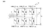
- FIG. 2A is a diagram for explaining the regenerative operation of the power conversion unit in the converter, and is a circuit diagram showing the power conversion unit including the three-phase bridge circuit.
- FIG. 2B is a diagram for explaining the regeneration operation of the power conversion unit in the converter, and is a diagram showing the relationship between the waveform of the three-phase AC power supply voltage at the time of power supply regeneration and the switching pattern of the switching element in the power element. ..
- FIGS. 2A and 2B a case where each phase of the three-phase AC power supply 4 and the input terminal 32 of the corresponding phase in the input voltage detection unit 12 are correctly wired will be described as an example.
- the power conversion unit 11 of the converter 1 has three legs, an R phase, an S phase, and a T phase.
- the leg of each phase has an upper arm and a lower arm.
- each arm is referred to as an R phase upper arm, an R phase lower arm, an S phase upper arm, an S phase lower arm, a T phase upper arm, and a T phase lower arm.
- a switching element S RU is provided on the upper arm of the R phase, and a switching element S RL is provided on the lower arm of the R phase.
- a switching element S SU is provided on the S-phase upper arm, and a switching element S SL is provided on the S-phase lower arm.
- a switching element S T U is provided on the T-phase upper arm, and a switching element S T L is provided on the T-phase lower arm.
- the control unit 13 When the power conversion unit 11 in the converter 1 is regenerated, the control unit 13 turns on and inputs a switching element provided on the upper arm of the phase in which the voltage detection value detected by the input voltage detection unit 12 is maximized.
- the switching element provided in each arm of each phase is controlled so that the switching element provided in the lower arm of the phase having the minimum voltage detection value detected by the voltage detection unit 12 is turned on.
- the R'phase and S' which are phase information for the control unit 13 to control the power conversion operation of the power conversion unit 11, to the voltage detection values for the three phases detected by the input voltage detection unit 12. Phases and T'phases are assigned.
- the control unit 13 is the power conversion unit 11.
- the switching element S RU of the R phase upper arm and the switching element S TL of the T phase lower arm are controlled to be turned on, and the switching elements of the other arms are controlled to be turned off.
- the control unit 13 is the switching element S SU of the S phase upper arm of the power conversion unit 11.
- the switching element S TL of the T-phase lower arm is controlled to be on, and the switching elements of the other arms are controlled to be off.
- the control unit 13 is the switching element S SU of the S phase upper arm of the power conversion unit 11.
- the switching elements S RL of the lower arm and the R phase lower arm are controlled to be on, and the switching elements of the other arms are controlled to be turned off.
- the control unit 13 is the switching element ST U of the T-phase upper arm of the power conversion unit 11.
- the switching elements S RL of the lower arm and the R phase lower arm are controlled to be on, and the switching elements of the other arms are controlled to be turned off.
- the control unit 13 is the switching element ST U of the T-phase upper arm of the power conversion unit 11. And the switching element S SL of the S phase lower arm is controlled to be turned on, and the switching elements of the other arms are controlled to be turned off.
- the control unit 13 is the switching element S RU of the R phase upper arm of the power conversion unit 11. And the switching element S SL of the S phase lower arm is controlled to be turned on, and the switching elements of the other arms are controlled to be turned off.
- the ON state exists for each switching element over the phase section of 120 degrees per cycle of the three-phase AC power supply 4, and the input voltage.
- the switching element to be turned on is switched.
- the regenerative current detection unit 14 executes arithmetic processing by the control unit 13 using the normal phase information and the voltage detection value detected by the input voltage detection unit 12, and the power conversion unit 11
- the input current detection unit 31 generally provided in the converter 1 may be diverted. That is, the input current detection unit 31 generally provided detects the value of the current (for example, power running current) flowing from the three-phase AC power supply 4 side to the power conversion unit 11 during the rectification operation, and from the power conversion unit 11 during the regeneration operation.
- the value of the regenerative current flowing out to the three-phase AC power supply 4 is detected.
- the regenerative current detection unit 14 may be realized.
- the wiring state detection unit 15 detects the wiring state between the input voltage detection unit 12 and the three-phase AC power supply 4 based on the comparison between the regenerative current value detected by the regenerative current detection unit 14 and a predetermined threshold value. .. That is, when the wiring state detection unit 15 determines that the wiring between the input voltage detection unit and the three-phase AC power supply is correct when the regenerative current value is equal to or less than the threshold value, the wiring state detection unit 15 determines that the wiring between the input voltage detection unit and the three-phase AC power supply is correct, and when the regenerative current value is larger than the threshold value. Determines that there is an error in the wiring between the input voltage detection unit and the three-phase AC power supply.
- the regenerative current flowing from the power conversion unit 11 to the three-phase AC power supply 4 is the input voltage detection unit 12 when there is an erroneous wiring between the input terminal 32 of the input voltage detection unit 12 and the three-phase AC power supply 4. This is larger than when the input terminal 32 and the three-phase AC power supply 4 are correctly wired. The reason for this will be described with reference to FIGS. 3A, 3B, 4A and 4B.
- FIG. 3A is a circuit diagram illustrating the relationship between the wiring state and the regenerative current between the three-phase AC power supply and the input voltage detection unit, and shows each phase of the three-phase AC power supply and the input terminal of the input voltage detection unit. Shows the case where the wiring is correct.
- FIG. 3B is a circuit diagram illustrating the relationship between the wiring state and the regenerative current between the three-phase AC power supply and the input voltage detection unit, and shows each phase of the three-phase AC power supply and the input terminal of the input voltage detection unit. Indicates a case where there is an incorrect wiring between.
- the components of the converter 1 other than the power conversion unit 11, the input voltage detection unit 12, and the input terminal 32 are not shown. Further, in FIGS. 3A and 3B, the inverter 3 and the motor 5 are not shown.
- FIG. 4A is a waveform diagram showing the positive and negative potentials of the DC link voltage and the voltage detection value detected by the input voltage detection unit during the regenerative operation of the converter, and is a waveform diagram of the three-phase AC power supply as shown in FIG. 3A. The case where each phase and the input terminal of the input voltage detection part are correctly wired is shown.
- FIG. 4B is a waveform diagram showing the positive and negative potentials of the DC link voltage and the voltage detection value detected by the input voltage detection unit during the regenerative operation of the converter, and is a waveform diagram of the three-phase AC power supply as shown in FIG. 3B. The case where there is an erroneous wiring between each phase and the input terminal of an input voltage detection unit is shown.
- the voltage of the R phase of the three-phase AC power supply 4 Is detected as an R'phase voltage detection value by the input voltage detection unit 12, and the S-phase voltage of the three-phase AC power supply 4 is detected as an S'phase voltage detection value by the input voltage detection unit 12, and is a three-phase AC power supply.
- the T-phase voltage of 4 is detected as a T'phase voltage detection value by the input voltage detection unit 12, and is sent to the control unit 13, respectively.
- the control unit 13 sets the voltage detection values of the R phase, T phase, and S phase of the three-phase AC power supply 4 input to the power conversion unit 11 to the R'phase, T'phase, and S'phase.
- the "three-phase AC power supply 4" The "S-phase” voltage is detected by the input voltage detection unit 12 as the R'phase voltage detection value, and the "R-phase” voltage of the three-phase AC power supply 4 is detected by the input voltage detection unit 12 as the S'phase voltage detection value.
- the voltage of the T phase of the three-phase AC power supply 4 is detected by the input voltage detection unit 12 as a voltage detection value of the T'phase, and each is sent to the control unit 13.
- the order of the R'phase, S'phase, and T'phase set for controlling the power conversion operation of the converter 1 by the control unit 13 is the order of the S phase, R phase, and T phase of the three-phase AC power supply 4. Does not match.
- the control unit 13 recognizes the T-phase voltage detection value as the T'phase voltage detection value, but recognizes the S-phase voltage detection value as the R'phase voltage detection value.
- the voltage detection value of the R phase is recognized as the voltage detection value of the S'phase. That is, the control unit 13 detects the voltage detection values of the R'phase, S'phase, and T'phase of the original R phase, T phase, and S phase of the three-phase AC power supply 4 input to the power conversion unit 11.
- the regenerative operation of the power conversion unit 11 is controlled. Therefore, as shown in FIG. 4B, since the switching element corresponding to the phase whose voltage detection value is not the maximum is turned on, the voltage detection corresponding to the positive potential V dcP of the DC link voltage and the switching element of the turned on phase. The potential difference (white arrow) from the value (that is, the voltage detection value of the non-maximum phase) becomes large. Similarly, the potential difference (blank arrow) between the negative potential V dcN of the DC link voltage and the voltage detection value corresponding to the switching element of the turned-on phase (that is, the voltage detection value of the non-minimum phase) becomes large. Therefore, the regenerative current flowing from the power conversion unit 11 to the three-phase AC power supply 4 becomes large.
- the control unit 13 executes arithmetic processing using the voltage detection value and the normal phase information to regenerate the power conversion unit 11. If the regenerative current value is less than or equal to the predetermined threshold value, it is determined that the wiring between the input voltage detection unit 12 and the three-phase AC power supply 4 is correct, and the regenerative current value is higher than the threshold value. If it is large, it is determined that there is an error in the wiring between the input voltage detection unit 12 and the three-phase AC power supply 4. Therefore, the wiring state detection unit 15 has an allocation unit 21 and a determination unit 22.
- the allocation unit 21 allocates regular phase information to each phase of the voltage detection value used in the arithmetic processing for controlling the regenerative operation of the power conversion unit 11 by the control unit 13.
- the "normal" phase information means that the power conversion unit 11 normally performs the regeneration operation under the control of the control unit 13 in a state where the input terminal 32 of the input voltage detection unit 12 and the three-phase AC power supply 4 are correctly wired. It is the phase information assigned to the voltage detection value detected by the input voltage detection unit 12 so that it can be executed.
- the assigned regular phase information is sent to the control unit 13.
- the determination unit 22 determines that the regenerative current value is equal to or less than the threshold value. It is determined that the wiring between the input voltage detection unit 12 and the three-phase AC power supply 4 is correct, and if the value of the regenerative current is larger than the threshold value, the wiring between the input voltage detection unit 12 and the three-phase AC power supply 4 is used. Judge that there is an error. Since the regenerative current detection unit 14 provided in the input current detection unit 31 detects the regenerative current for two or three phases, the determination unit 22 determines the value and the threshold value of the regenerative current for each phase.
- the determination unit 22 converts the input current for the two phases detected by the regenerative current detection unit 14 into a vector norm on the two-phase coordinates, and when the vector norm is larger than the threshold value, the determination unit 22 and the input voltage detection unit 12 It may be determined that there is an error in the wiring to and from the three-phase AC power supply 4.
- the threshold value used for the wiring state detection process may be set as follows. For example, in the motor drive device 100, a threshold value for detecting the generation of overcurrent on the AC input side of the power conversion unit 11 of the converter 1 may be set, and this threshold value is used for the wiring state detection process. It may be used in combination with. Further, for example, before the motor drive device 100 is shipped from the factory, the control unit 13 correctly wires the input terminal 32 of the input voltage detection unit 12 and the three-phase AC power supply 4, and then the control unit 13 determines the voltage detection value and the regular phase information.
- the power conversion unit 11 is regenerated by executing arithmetic processing using the above, a value that is, for example, several tens of percent higher than the value of the regenerative current detected by the regenerative current detection unit 14 is set as the threshold value. good.
- the numerical example shown here is just an example, and may be a value other than this. Further, for example, by simulation with a computer, the regenerative operation of the power conversion unit 11 under the state where the input terminal 32 of the input voltage detection unit 12 and the three-phase AC power supply 4 are correctly wired is reproduced, and the power of the converter 1 is reproduced.
- the threshold value may be set after obtaining in advance the relationship between the current value (regenerative current value) on the AC input side of the conversion unit 11 and the presence / absence of the output of the alarm signal in the motor drive device 100.
- the threshold value may be stored in a rewritable storage unit (not shown) and rewritable by an external device. According to this, even after the threshold value is once set, it is appropriate as necessary. Can be changed to any value.
- the wiring state detection result (determination result) by the wiring state detection unit 15 is displayed on, for example, a display unit (not shown).
- Examples of the display unit include a single display device, a display device attached to the converter 1, a display device attached to the motor drive device 100, and a display device attached to a personal computer and a mobile terminal.
- the wiring state detection result (determination result) by the wiring state detection unit 15 may be output by an audio device that emits a sound such as a voice, a speaker, a buzzer, or a chime.
- the operator can easily grasp that there is an erroneous wiring between the three-phase AC power supply 4 and the input voltage detection unit 12 in the converter 1. Therefore, it becomes easy for the operator to correctly reconnect the power line of each phase from the three-phase AC power supply to the input terminal of the corresponding phase in the input voltage detection unit.
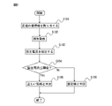
- FIG. 5 is a flowchart showing an operation flow of wiring state detection processing in the converter and the motor drive device according to the first embodiment of the present disclosure.
- the wiring work between the input terminal 32 of the input voltage detection unit 12 and the power line of each phase of the three-phase AC power supply 4 is performed by the operator at the time of installation or maintenance of the motor drive device 100. When done, it will be executed.
- the allocation unit 21 in the wiring state detection unit 15 has regular phase information for each phase of the voltage detection value used for the arithmetic processing for controlling the regenerative operation of the power conversion unit 11 by the control unit 13. To assign. The assigned regular phase information is sent to the control unit 13.
- step S102 the control unit 13 executes arithmetic processing using the voltage detection value detected by the input voltage detection unit 12 and the normal phase information assigned by the allocation unit 21, and regenerates the power conversion unit 11. Control.
- step S103 the regenerative current detection unit 14 detects the value of the regenerative current flowing from the power conversion unit 11 to the three-phase AC power supply 4 side.
- step S104 the value of the regenerative current detected by the regenerative current detection unit 14 is compared with the threshold value, and it is determined whether or not the value of the regenerative current is equal to or less than the threshold value. If it is determined that the regenerative current value is equal to or less than the threshold value, the process proceeds to step S105, and if it is determined that the regenerative current value is larger than the threshold value, the process proceeds to step S106.
- step S105 the determination unit 22 in the wiring state detection unit 15 determines that the wiring between the input voltage detection unit 12 and the three-phase AC power supply 4 is correct.
- step S106 the determination unit 22 in the wiring state detection unit 15 determines that there is an error in the wiring between the input voltage detection unit 12 and the three-phase AC power supply 4. If it is determined that there is an error in the wiring between the input voltage detection unit 12 and the three-phase AC power supply 4, the control unit 13 suppresses the generation of regenerative current by controlling all switching elements off. You may try to do it. This makes it possible to more reliably prevent failures of the converter 1 and the motor drive device 100.
- the wiring state detection result (determination result) by the determination unit 22 in the wiring state detection unit 15 in steps S105 and S106 is displayed on, for example, a display unit (not shown) or output by an audio device.
- a display unit not shown
- an audio device As a result, the operator can easily grasp whether the wiring is erroneous or normal between the three-phase AC power supply 4 and the input voltage detection unit 12 in the converter 1. Therefore, when the operator confirms that there is an erroneous wiring between the input voltage detection unit 12 and the three-phase AC power supply 4, the operator can take measures such as rewiring correctly. When the operator confirms that the wiring between the input voltage detection unit 12 and the three-phase AC power supply 4 is normal, the operator can start preparing for the normal operation of the motor drive device 100.
- the first embodiment is further extended, and based on the wiring state detection result by the wiring state detection unit 15 described above, the phase information setting unit 16 automatically obtains the normal phase information used for the arithmetic processing by the control unit 13. It may be set to.
- the setting process of the normal phase information will be described.
- provisional phase information which is provisional phase information for each phase of the voltage detection value used in the arithmetic processing for controlling the regenerative operation of the power conversion unit 11 by the control unit 13. Is assigned. While the wiring state detection process is being executed by the wiring state detection unit 15, the control unit 13 executes arithmetic processing using the voltage detection value of each phase detected by the input voltage detection unit 12 and the provisional phase information, and performs power conversion. The power conversion operation of unit 11 is controlled.
- the determination unit 22 inputs if the value of the regeneration current is equal to or less than the threshold value. It is determined that the wiring between the voltage detection unit 12 and the three-phase AC power supply 4 is correct, and if the value of the regenerative current is larger than the threshold value, the wiring between the input voltage detection unit 12 and the three-phase AC power supply 4 is incorrect. It is determined that there is.
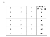
- FIG. 6 is a diagram illustrating the relationship between the phase of the three-phase AC power supply and the phase defined by the provisional phase information. It is necessary to set three phases, that is, the first phase, the second phase, and the third phase for controlling the power conversion operation of the converter 1 by the control unit 13 corresponding to the number of phases "3" of the three-phase AC power supply 4. be. Therefore, there are a total of 6 patterns of provisional phase information assigned by the allocation unit 21 to the voltage detection value of each phase. That is, the first provisional phase information in which the first phase is the R'phase, the second phase is the S'phase, and the third phase is the T'phase, and the first phase is the R'phase and the second phase.
- the S-phase power line of the three-phase AC power supply 4 is connected to the terminal corresponding to the first phase of the input terminals 32 of the input voltage detection unit 12.
- the power line of the R phase of the three-phase AC power supply 4 is connected to the terminal corresponding to the second phase of the input terminal 32 of the input voltage detection unit 12, and the third of the input terminals 32 of the input voltage detection unit 12 is connected.
- An example in which the T-phase power line of the three-phase AC power supply 4 is connected to the terminal corresponding to the phase of the above will be described.
- the phase order defined by the first, second, and fourth to sixth provisional phase information is the three-phase AC power supply 4 connected to the input terminal 32 of the input voltage detection unit 12. Since the phase order does not match, when the control unit 13 controls the regenerative operation of the power conversion unit 11 using these provisional phase information and the voltage detection value, the regenerative current detected by the regenerative current detection unit 14 is executed. The value of becomes large and exceeds the threshold. Therefore, the determination unit 22 determines that there is an error in the wiring between the input voltage detection unit 12 and the three-phase AC power supply 4.
- the determination unit 22 determines that the wiring between the input voltage detection unit 12 and the three-phase AC power supply 4 is correct.
- the phase information setting unit 16 controls the provisional phase information assigned by the allocation unit 21 when the determination unit 22 determines that the wiring between the input voltage detection unit 12 and the three-phase AC power supply 4 is correct. It is set as normal phase information used for the arithmetic processing by 13. The set regular phase information is stored in the storage unit 23, and the phase information setting process is completed. After that, the control unit 13 executes arithmetic processing using the voltage detection value of each phase detected by the input voltage detection unit 12 and the normal phase information stored in the storage unit 23, and the power of the power conversion unit 11 Control the conversion operation. Since the regular phase information set by the phase information setting unit 16 is stored in the storage unit 23, even when the power is turned on again after the power of the converter 1 and the motor drive device 100 is turned off, the storage unit is stored. The regular phase information stored in 23 can be used.
- the allocation unit 21 determines the provisional phase information assigned at the time of the determination. Instead, set new provisional phase information.
- the control unit 13 executes arithmetic processing using the voltage detection value of each phase detected by the input voltage detection unit 12 and the provisional phase information, controls the power conversion operation of the power conversion unit 11, and the determination unit 22 controls this. The judgment process is executed under the state. Until the determination unit 22 determines that the wiring between the input voltage detection unit 12 and the three-phase AC power supply 4 is correct, the allocation unit 21 changes and allocates the provisional phase information, and the control unit 13 is assigned.
- the regenerative operation of the power conversion unit 11 is controlled by the provisional phase information. As described above, since there are a total of 6 patterns of provisional phase information, the provisional phase information allocation processing and regeneration are performed until the determination unit 22 determines that the wiring between the input voltage detection unit 12 and the three-phase AC power supply 4 is correct. The current determination process is performed up to 6 times.
- FIG. 7 is a flowchart showing an operation flow of phase information setting processing in the converter and the motor drive device according to the first embodiment of the present disclosure.
- step S201 the allocation unit 21 in the wiring state detection unit 15 provides provisional phase information for each phase of the voltage detection value used in the arithmetic processing for controlling the regenerative operation of the power conversion unit 11 by the control unit 13. assign. The assigned provisional phase information is sent to the control unit 13.
- step S202 the control unit 13 executes arithmetic processing using the voltage detection value detected by the input voltage detection unit 12 and the provisional phase information assigned by the allocation unit 21 to control the regenerative operation of the power conversion unit 11. do.
- step S203 the regenerative current detection unit 14 detects the value of the regenerative current flowing from the power conversion unit 11 to the three-phase AC power supply 4 side.
- step S204 the value of the regenerative current detected by the regenerative current detection unit 14 is compared with the threshold value, and it is determined whether or not the value of the regenerative current is equal to or less than the threshold value. If it is determined that the regenerative current value is equal to or less than the threshold value, the process proceeds to step S205, and if it is determined that the regenerative current value is larger than the threshold value, the process proceeds to step S206.
- step S206 When it is determined in step S204 that the value of the regenerative current is larger than the threshold value, in step S206, the allocation unit 21 sets new provisional phase information in place of the provisional phase information assigned at the time of the determination. do. After that, the process returns to step S202. Processing of steps S202 to S204 and S206 until the value of the regenerative current is determined to be equal to or less than the threshold value in step S204 (that is, until the wiring between the input voltage detection unit 12 and the three-phase AC power supply 4 is determined to be correct). Is executed repeatedly (up to 6 times).
- step S205 the determination unit 22 determines that the wiring between the input voltage detection unit 12 and the three-phase AC power supply 4 is correct, and this The provisional phase information that was sometimes assigned by the allocation unit 21 is set as the normal phase information used for the arithmetic processing by the control unit 13.
- the set regular phase information is stored in the storage unit 23, and the wiring state detection process by the wiring state detection unit 15 is completed.
- the control unit 13 uses the voltage detection value of each phase detected by the input voltage detection unit 12 and the normal phase information stored in the storage unit 23. The calculation process is executed to control the power conversion operation of the power conversion unit 11.
- the wiring state detection process and phase information of the wiring state detection unit 15 By the phase information setting process of the setting unit 16, the phase information that enables the power conversion unit 11 to normally regenerate can be automatically assigned to the voltage detection value detected by the input voltage detection unit 12. Therefore, it is possible to prevent the alarm stop and failure of the converter 1 and the motor drive device 100 due to incorrect wiring. Further, since appropriate phase information is automatically assigned to the voltage detection value, it is not necessary to rewire the input voltage detection unit 12 and the three-phase AC power supply 4, and the motor drive device 100 is operated. Work efficiency is improved.
- phase information that enables the power conversion unit 11 to regenerate normally is automatically set, so that the alarm of the converter 1 and the motor drive device 100 is alarmed. It is possible to prevent stoppage and failure.
- the second embodiment is the same as that of the first embodiment.
- the regenerative current flowing from the power conversion unit 11 to the three-phase AC power supply 4 is between the input terminal 32 of the input voltage detection unit 12 and the three-phase AC power supply 4. It utilizes the characteristic that "the case where there is an incorrect wiring is larger than the case where the wiring is correct".
- the control unit executes arithmetic processing using the voltage detection value and the provisional phase information to control the regenerative operation of the power conversion unit
- the regenerative current detection unit determines the minimum regenerative current. It differs from the first embodiment in that the provisional phase information assigned by the allocation unit when the value is detected is set as the normal phase information used for the arithmetic processing by the control unit.
- FIG. 8 is a diagram showing a converter and a motor drive device according to the second embodiment of the present disclosure.
- the motor 5 is controlled by the motor drive device 100 connected to the three-phase AC power supply 4
- the three-phase AC power supply 4 include a three-phase AC 400V power supply, a three-phase AC 200V power supply, and a three-phase AC 600V power supply.
- the type of the motor 5 is not particularly limited, and may be, for example, an induction motor or a synchronous motor.
- the number of phases of the motor 5 is not particularly limited to this embodiment, and may be, for example, three-phase or single-phase.
- the motor 5 is a three-phase AC motor.
- Machines provided with the motor 5 include, for example, machine tools, robots, forging machines, injection molding machines, industrial machines and the like.
- the motor drive device 100 includes a converter 1, an inverter 3, a DC link capacitor 6, and an AC reactor 7. Further, the converter 1 according to the second embodiment of the present disclosure includes a power conversion unit 11, an input voltage detection unit 12, a control unit 13, a regenerative current detection unit 14, an allocation unit 17, and a phase information setting unit 18. And prepare.
- the inverter 3, the DC link capacitor 6, the AC reactor 7, the power conversion unit 11, the input voltage detection unit 12, the control unit 13, and the regenerative current detection unit 14 are the same as those in the first embodiment.
- the allocation unit 17 allocates provisional phase information to each phase of the voltage detection value used in the arithmetic processing for controlling the regenerative operation of the power conversion unit 11 by the control unit 13.
- the provisional phase information is as described with respect to the first embodiment. While the phase information setting process by the phase information setting unit 18 is being executed, the control unit 13 executes arithmetic processing using the voltage detection value of each phase detected by the input voltage detection unit 12 and the provisional phase information, and performs power conversion. The power conversion operation of unit 11 is controlled. As described above, there are a total of 6 patterns of provisional phase information assigned by the allocation unit 17 to the voltage detection value of each phase, but the regenerative operation of the power conversion unit 11 by the control unit 13 for the provisional phase information of all 6 patterns.
- the regenerative current detection unit 14 detects the value of the regenerative current by executing the control of. That is, the regenerative current detection unit 14 detects six types of regenerative current values corresponding to the six patterns of provisional phase information. The detected regenerative current value is stored in the storage unit 23 in association with the corresponding provisional phase information.
- the regenerative current detection unit 14 controls the minimum regenerative current.
- the provisional phase information assigned by the allocation unit 17 when the value of is detected is read from the storage unit 23, and is set as the normal phase information used for the arithmetic processing by the control unit 13.
- the set regular phase information is stored in the storage unit 23, and the phase information setting process is completed.
- the control unit 13 executes arithmetic processing using the voltage detection value of each phase detected by the input voltage detection unit 12 and the normal phase information stored in the storage unit 23, and the power of the power conversion unit 11 Control the conversion operation. Since the regular phase information set by the phase information setting unit 18 is stored in the storage unit 23, even when the power is turned on again after the power of the converter 1 and the motor drive device 100 is cut off, the storage unit is stored.
- the regular phase information stored in 23 can be used.
- FIG. 9 is a flowchart showing an operation flow of phase information setting processing in the converter and the motor drive device according to the first embodiment of the present disclosure.
- the wiring work between the input terminal 32 of the input voltage detection unit 12 and the power line of each phase of the three-phase AC power supply 4 is performed by the operator at the time of installation or maintenance of the motor drive device 100. When done, it will be executed.
- the identification number N (however, 1). Identify using ⁇ N ⁇ 6).
- step S301 the allocation unit 17 sets the identification number N of the provisional phase information to 1 as an initial setting.
- the setting of the identification number N 1 of the provisional phase information in step S301 may be performed by, for example, an input operation using an input device to the converter 1 of the operator, or the phase information setting process by the phase information setting unit 18. It may be automatically performed at the start of the operation, or it may be automatically performed when the power of the motor drive device 100 or the converter 1 is turned on.
- step S302 the allocation unit 17 allocates the Nth provisional phase information to each phase of the voltage detection value used for the arithmetic processing for controlling the regenerative operation of the power conversion unit 11 by the control unit 13.
- the assigned Nth provisional phase information is sent to the control unit 13.
- step S303 the control unit 13 executes arithmetic processing using the voltage detection value detected by the input voltage detection unit 12 and the Nth provisional phase information assigned by the allocation unit 21, and the power conversion unit 11 Controls the regeneration operation.
- step S304 the regenerative current detection unit 14 detects the value of the regenerative current flowing from the power conversion unit 11 to the three-phase AC power supply 4 side, and stores the value in the storage unit 23.
- step S305 the allocation unit 17 determines whether or not the identification number N of the provisional phase information is 6. If it is determined that the identification number N of the provisional phase information is 6, the process proceeds to step S306, and if it is not determined that the identification number N of the provisional phase information is 6, the process proceeds to step S307.
- step S307 the allocation unit 17 increments the identification number N of the provisional phase information by one. After that, the process returns to step S302.
- the phase information setting unit 18 is the allocation unit 17 when the minimum regenerative current value is detected from the six types of regenerative current values corresponding to the six patterns of provisional phase information stored in the storage unit 23.
- the provisional phase information assigned by is read out and set as normal phase information used for arithmetic processing by the control unit 13.
- the set regular phase information is stored in the storage unit 23, and the phase information setting process is completed.
- the control unit 13 executes arithmetic processing using the voltage detection value of each phase detected by the input voltage detection unit 12 and the normal phase information stored in the storage unit 23, and the power of the power conversion unit 11 Control the conversion operation.
- phase information that enables the power conversion unit 11 to normally regenerate can be automatically assigned to the voltage detection value detected by the voltage detection unit 12. Therefore, it is possible to prevent the alarm stop and failure of the converter 1 and the motor drive device 100 due to incorrect wiring. Further, since appropriate phase information is automatically assigned to the voltage detection value, it is not necessary to rewire the input voltage detection unit 12 and the three-phase AC power supply 4, and the motor drive device 100 is operated. Work efficiency is improved. For example, even if the operator is unfamiliar with the wiring work and makes a mistake in wiring, it is possible to prevent the alarm stop or failure of the converter 1 and the motor drive device 100.
- the control unit 13, the wiring state detection unit 15, the phase information setting units 16 and 18, and the allocation unit 17 may be configured only by an arithmetic processing unit, or may be configured by a combination of an analog circuit and an arithmetic processing unit. It may be well composed of analog circuits only. Arithmetic processing devices that can configure the control unit 13, the wiring state detection unit 15, the phase information setting units 16 and 18, and the allocation unit 17 include, for example, an IC, an LSI, a CPU, an MPU, and a DSP. For example, when the control unit 13, the wiring state detection unit 15, the phase information setting units 16 and 18, and the allocation unit 17 are constructed in the form of a software program, the control unit 13 is operated by operating the arithmetic processing unit according to this software program.
- the wiring state detection unit 15, the phase information setting units 16 and 18, and the allocation unit 17 can be realized.
- the control unit 13, the wiring state detection unit 15, the phase information setting units 16 and 18, and the allocation unit 17 may be realized as a semiconductor integrated circuit in which a software program for realizing the functions of each unit is written.
- the control unit 13, the wiring state detection unit 15, the phase information setting units 16 and 18, and the allocation unit 17 may be realized as a recording medium in which a software program that realizes the functions of each unit is written.
- the control unit 13, the wiring state detection unit 15, the phase information setting units 16 and 18, and the allocation unit 17 may be provided in, for example, a numerical control device of a machine tool, or in a robot controller that controls the robot. It may be provided.
- the storage unit 23 is composed of a non-volatile memory that can be electrically erased and recorded, such as EEPROM (registered trademark), or a random access memory that can be read and written at high speed, such as DRAM and SRAM. ..
- the input voltage detection unit 12 and the regenerative current detection unit 14 may be configured by a combination of an analog circuit and an arithmetic processing unit, may be composed of only an arithmetic processing unit, or may be composed of only an analog circuit. May be good. As the input voltage detection unit 12 and the regenerative current detection unit 14, those generally provided in the converter 1 or the motor drive device 100 may be diverted.
Landscapes
- Engineering & Computer Science (AREA)
- Power Engineering (AREA)
- Inverter Devices (AREA)
- Rectifiers (AREA)
Priority Applications (4)
| Application Number | Priority Date | Filing Date | Title |
|---|---|---|---|
| DE112021004457.5T DE112021004457T5 (de) | 2020-10-26 | 2021-10-19 | Wandler, aufweisend eine Verdrahtungszustands-Erfassungseinheit, und Motorantriebsvorrichtung |
| US18/042,456 US20230327573A1 (en) | 2020-10-26 | 2021-10-19 | Converter having wiring state detection unit and motor drive device |
| CN202180071218.4A CN116325470A (zh) | 2020-10-26 | 2021-10-19 | 具有配线状态检测部的转换器以及电动机驱动装置 |
| JP2022559044A JP7575477B2 (ja) | 2020-10-26 | 2021-10-19 | 配線状態検出部を有するコンバータ及びモータ駆動装置 |
Applications Claiming Priority (2)
| Application Number | Priority Date | Filing Date | Title |
|---|---|---|---|
| JP2020-178705 | 2020-10-26 | ||
| JP2020178705 | 2020-10-26 |
Publications (1)
| Publication Number | Publication Date |
|---|---|
| WO2022091884A1 true WO2022091884A1 (ja) | 2022-05-05 |
Family
ID=81383837
Family Applications (1)
| Application Number | Title | Priority Date | Filing Date |
|---|---|---|---|
| PCT/JP2021/038652 Ceased WO2022091884A1 (ja) | 2020-10-26 | 2021-10-19 | 配線状態検出部を有するコンバータ及びモータ駆動装置 |
Country Status (5)
| Country | Link |
|---|---|
| US (1) | US20230327573A1 (https=) |
| JP (1) | JP7575477B2 (https=) |
| CN (1) | CN116325470A (https=) |
| DE (1) | DE112021004457T5 (https=) |
| WO (1) | WO2022091884A1 (https=) |
Cited By (1)
| Publication number | Priority date | Publication date | Assignee | Title |
|---|---|---|---|---|
| JP7674715B2 (ja) | 2022-12-16 | 2025-05-12 | Anp株式会社 | 双方向電力連系装置 |
Families Citing this family (2)
| Publication number | Priority date | Publication date | Assignee | Title |
|---|---|---|---|---|
| EP4280445B1 (en) * | 2021-01-14 | 2025-06-04 | Mitsubishi Electric Corporation | Power conversion device |
| JP7691644B2 (ja) * | 2022-09-28 | 2025-06-12 | トヨタ自動車株式会社 | 電力変換装置 |
Citations (3)
| Publication number | Priority date | Publication date | Assignee | Title |
|---|---|---|---|---|
| JP2006340466A (ja) * | 2005-06-01 | 2006-12-14 | Fuji Electric Fa Components & Systems Co Ltd | Pwmコンバータ制御装置 |
| JP2014195375A (ja) * | 2013-03-29 | 2014-10-09 | Hitachi Industrial Equipment Systems Co Ltd | 電力変換装置 |
| JP2020058184A (ja) * | 2018-10-03 | 2020-04-09 | ファナック株式会社 | 電力供給モード切替え機能を有するモータ駆動装置 |
Family Cites Families (9)
| Publication number | Priority date | Publication date | Assignee | Title |
|---|---|---|---|---|
| JP3565054B2 (ja) | 1998-11-02 | 2004-09-15 | 松下電器産業株式会社 | インバータ装置の保護方法 |
| JP4761117B2 (ja) | 2005-06-14 | 2011-08-31 | 富士電機株式会社 | 交流交流変換器の異常検出方法 |
| WO2008053554A1 (fr) * | 2006-11-02 | 2008-05-08 | Mitsubishi Electric Corporation | Appareil de commande de voiture à moteur électrique |
| JP2008253008A (ja) | 2007-03-29 | 2008-10-16 | Mitsubishi Electric Corp | 電力変換装置および電源誤接続判定方法 |
| JP4696146B2 (ja) * | 2008-06-27 | 2011-06-08 | 株式会社日立製作所 | 断線検出方法および電力変換装置 |
| JP6000558B2 (ja) * | 2012-01-27 | 2016-09-28 | 住友重機械工業株式会社 | 射出成形機及びコンバータ |
| JP2013199099A (ja) * | 2012-03-26 | 2013-10-03 | Sumitomo Heavy Ind Ltd | 射出成形機及びコンバータ |
| CN109643959B (zh) * | 2017-03-09 | 2020-11-06 | 三菱电机株式会社 | 电力变换装置以及逻辑电路 |
| CN111670539B (zh) * | 2018-02-08 | 2023-06-23 | 三菱电机株式会社 | 电动机的控制装置及电缆断线检测方法 |
-
2021
- 2021-10-19 WO PCT/JP2021/038652 patent/WO2022091884A1/ja not_active Ceased
- 2021-10-19 JP JP2022559044A patent/JP7575477B2/ja active Active
- 2021-10-19 CN CN202180071218.4A patent/CN116325470A/zh active Pending
- 2021-10-19 US US18/042,456 patent/US20230327573A1/en not_active Abandoned
- 2021-10-19 DE DE112021004457.5T patent/DE112021004457T5/de active Pending
Patent Citations (3)
| Publication number | Priority date | Publication date | Assignee | Title |
|---|---|---|---|---|
| JP2006340466A (ja) * | 2005-06-01 | 2006-12-14 | Fuji Electric Fa Components & Systems Co Ltd | Pwmコンバータ制御装置 |
| JP2014195375A (ja) * | 2013-03-29 | 2014-10-09 | Hitachi Industrial Equipment Systems Co Ltd | 電力変換装置 |
| JP2020058184A (ja) * | 2018-10-03 | 2020-04-09 | ファナック株式会社 | 電力供給モード切替え機能を有するモータ駆動装置 |
Cited By (1)
| Publication number | Priority date | Publication date | Assignee | Title |
|---|---|---|---|---|
| JP7674715B2 (ja) | 2022-12-16 | 2025-05-12 | Anp株式会社 | 双方向電力連系装置 |
Also Published As
| Publication number | Publication date |
|---|---|
| JP7575477B2 (ja) | 2024-10-29 |
| US20230327573A1 (en) | 2023-10-12 |
| DE112021004457T5 (de) | 2023-06-07 |
| CN116325470A (zh) | 2023-06-23 |
| JPWO2022091884A1 (https=) | 2022-05-05 |
Similar Documents
| Publication | Publication Date | Title |
|---|---|---|
| JP7575477B2 (ja) | 配線状態検出部を有するコンバータ及びモータ駆動装置 | |
| US10090795B2 (en) | Motor drive having function of protecting dynamic braking circuit | |
| CN109391175B (zh) | 电动机控制装置和机床系统 | |
| US10651758B2 (en) | Motor drive apparatus including short-circuit judgment unit for capacitor of DC link unit | |
| US11211892B2 (en) | Motor drive apparatus configured to determine cause of DC link voltage fluctuation | |
| JP6431132B1 (ja) | 漏れ電流の大きい逆変換器を検知するモータ駆動装置 | |
| JP2000139076A (ja) | Pwmサイクロコンバータの保護装置およびその保護方法 | |
| JP2013085325A (ja) | 3レベル電力変換回路システム | |
| JP2016116432A (ja) | コンバータ装置、インバータ装置及び交流機駆動装置 | |
| JP7578701B2 (ja) | Pwmコンバータに接続されるフィルタ及びコンバータシステム | |
| CN101009427A (zh) | 电源设备 | |
| CN108347213B (zh) | 电动机驱动装置 | |
| CN101385236A (zh) | 接地故障检测方法 | |
| JP2008172925A (ja) | マトリックスコンバータのバックアップ運転装置 | |
| JP6131940B2 (ja) | インバータの故障検出方法およびインバータ検査装置 | |
| JP5427787B2 (ja) | 三相整流装置 | |
| JP7381756B2 (ja) | モータの絶縁抵抗値を計算するモータ駆動装置 | |
| JP7469036B2 (ja) | 保護機構を有するモータ駆動装置 | |
| JP6455938B2 (ja) | 電力変換装置及びその制御方法 | |
| JP6757112B2 (ja) | 電力変換装置および電力変換装置の状態判定方法 | |
| JP6643957B2 (ja) | 電力変換装置及びその制御方法 | |
| CN114600360B (zh) | 转换器及电动机控制系统 | |
| JP2001086751A (ja) | Pwmサイクロコンバータの保護装置とその保護方法 | |
| JP7529537B2 (ja) | 電力変換装置の故障を検出する故障検出装置及びモータ駆動装置 | |
| JP7372207B2 (ja) | リアクトルの層間短絡を検出するコンバータ装置 |
Legal Events
| Date | Code | Title | Description |
|---|---|---|---|
| 121 | Ep: the epo has been informed by wipo that ep was designated in this application |
Ref document number: 21886003 Country of ref document: EP Kind code of ref document: A1 |
|
| ENP | Entry into the national phase |
Ref document number: 2022559044 Country of ref document: JP Kind code of ref document: A |
|
| 122 | Ep: pct application non-entry in european phase |
Ref document number: 21886003 Country of ref document: EP Kind code of ref document: A1 |