WO2022091660A1 - 反射ユニット及び無線伝送システム - Google Patents
反射ユニット及び無線伝送システム Download PDFInfo
- Publication number
- WO2022091660A1 WO2022091660A1 PCT/JP2021/035080 JP2021035080W WO2022091660A1 WO 2022091660 A1 WO2022091660 A1 WO 2022091660A1 JP 2021035080 W JP2021035080 W JP 2021035080W WO 2022091660 A1 WO2022091660 A1 WO 2022091660A1
- Authority
- WO
- WIPO (PCT)
- Prior art keywords
- reflect array
- reflection unit
- reflector
- array reflector
- concentrated
- Prior art date
- Legal status (The legal status is an assumption and is not a legal conclusion. Google has not performed a legal analysis and makes no representation as to the accuracy of the status listed.)
- Ceased
Links
Images














Classifications
-
- H—ELECTRICITY
- H01—ELECTRIC ELEMENTS
- H01Q—ANTENNAS, i.e. RADIO AERIALS
- H01Q1/00—Details of, or arrangements associated with, antennas
- H01Q1/12—Supports; Mounting means
- H01Q1/22—Supports; Mounting means by structural association with other equipment or articles
- H01Q1/24—Supports; Mounting means by structural association with other equipment or articles with receiving set
-
- H—ELECTRICITY
- H01—ELECTRIC ELEMENTS
- H01Q—ANTENNAS, i.e. RADIO AERIALS
- H01Q3/00—Arrangements for changing or varying the orientation or the shape of the directional pattern of the waves radiated from an antenna or antenna system
- H01Q3/44—Arrangements for changing or varying the orientation or the shape of the directional pattern of the waves radiated from an antenna or antenna system varying the electric or magnetic characteristics of reflecting, refracting, or diffracting devices associated with the radiating element
- H01Q3/46—Active lenses or reflecting arrays
-
- H—ELECTRICITY
- H01—ELECTRIC ELEMENTS
- H01Q—ANTENNAS, i.e. RADIO AERIALS
- H01Q15/00—Devices for reflection, refraction, diffraction or polarisation of waves radiated from an antenna, e.g. quasi-optical devices
- H01Q15/14—Reflecting surfaces; Equivalent structures
-
- H—ELECTRICITY
- H01—ELECTRIC ELEMENTS
- H01Q—ANTENNAS, i.e. RADIO AERIALS
- H01Q15/00—Devices for reflection, refraction, diffraction or polarisation of waves radiated from an antenna, e.g. quasi-optical devices
- H01Q15/14—Reflecting surfaces; Equivalent structures
- H01Q15/16—Reflecting surfaces; Equivalent structures curved in two dimensions [2D], e.g. paraboloidal
-
- H—ELECTRICITY
- H01—ELECTRIC ELEMENTS
- H01Q—ANTENNAS, i.e. RADIO AERIALS
- H01Q15/00—Devices for reflection, refraction, diffraction or polarisation of waves radiated from an antenna, e.g. quasi-optical devices
- H01Q15/14—Reflecting surfaces; Equivalent structures
- H01Q15/18—Reflecting surfaces; Equivalent structures comprising plurality of mutually inclined plane surfaces, e.g. corner reflector
-
- H—ELECTRICITY
- H01—ELECTRIC ELEMENTS
- H01Q—ANTENNAS, i.e. RADIO AERIALS
- H01Q17/00—Devices for absorbing waves radiated from an antenna; Combinations of such devices with active antenna elements or systems
-
- H—ELECTRICITY
- H01—ELECTRIC ELEMENTS
- H01Q—ANTENNAS, i.e. RADIO AERIALS
- H01Q19/00—Combinations of primary active antenna elements and units with secondary devices, e.g. with quasi-optical devices, for giving the antenna a desired directional characteristic
- H01Q19/10—Combinations of primary active antenna elements and units with secondary devices, e.g. with quasi-optical devices, for giving the antenna a desired directional characteristic using reflecting surfaces
- H01Q19/106—Combinations of primary active antenna elements and units with secondary devices, e.g. with quasi-optical devices, for giving the antenna a desired directional characteristic using reflecting surfaces using two or more intersecting plane surfaces, e.g. corner reflector antennas
-
- H—ELECTRICITY
- H01—ELECTRIC ELEMENTS
- H01Q—ANTENNAS, i.e. RADIO AERIALS
- H01Q19/00—Combinations of primary active antenna elements and units with secondary devices, e.g. with quasi-optical devices, for giving the antenna a desired directional characteristic
- H01Q19/10—Combinations of primary active antenna elements and units with secondary devices, e.g. with quasi-optical devices, for giving the antenna a desired directional characteristic using reflecting surfaces
- H01Q19/18—Combinations of primary active antenna elements and units with secondary devices, e.g. with quasi-optical devices, for giving the antenna a desired directional characteristic using reflecting surfaces having two or more spaced reflecting surfaces
- H01Q19/185—Combinations of primary active antenna elements and units with secondary devices, e.g. with quasi-optical devices, for giving the antenna a desired directional characteristic using reflecting surfaces having two or more spaced reflecting surfaces wherein the surfaces are plane
-
- H—ELECTRICITY
- H01—ELECTRIC ELEMENTS
- H01Q—ANTENNAS, i.e. RADIO AERIALS
- H01Q19/00—Combinations of primary active antenna elements and units with secondary devices, e.g. with quasi-optical devices, for giving the antenna a desired directional characteristic
- H01Q19/10—Combinations of primary active antenna elements and units with secondary devices, e.g. with quasi-optical devices, for giving the antenna a desired directional characteristic using reflecting surfaces
- H01Q19/18—Combinations of primary active antenna elements and units with secondary devices, e.g. with quasi-optical devices, for giving the antenna a desired directional characteristic using reflecting surfaces having two or more spaced reflecting surfaces
- H01Q19/19—Combinations of primary active antenna elements and units with secondary devices, e.g. with quasi-optical devices, for giving the antenna a desired directional characteristic using reflecting surfaces having two or more spaced reflecting surfaces comprising one main concave reflecting surface associated with an auxiliary reflecting surface
-
- H—ELECTRICITY
- H01—ELECTRIC ELEMENTS
- H01Q—ANTENNAS, i.e. RADIO AERIALS
- H01Q21/00—Antenna arrays or systems
- H01Q21/06—Arrays of individually energised antenna units similarly polarised and spaced apart
-
- H—ELECTRICITY
- H04—ELECTRIC COMMUNICATION TECHNIQUE
- H04B—TRANSMISSION
- H04B7/00—Radio transmission systems, i.e. using radiation field
- H04B7/14—Relay systems
- H04B7/145—Passive relay systems
-
- H—ELECTRICITY
- H04—ELECTRIC COMMUNICATION TECHNIQUE
- H04B—TRANSMISSION
- H04B7/00—Radio transmission systems, i.e. using radiation field
- H04B7/14—Relay systems
- H04B7/15—Active relay systems
- H04B7/155—Ground-based stations
Definitions
- This disclosure relates to a reflection unit and a wireless transmission system.
- This application claims priority based on Japanese Application No. 2020-180447 filed on October 28, 2020, and incorporates all the contents described in the Japanese application.
- Patent Document 1 discloses a radio wave reflector used for an on-site information communication system including a parent transceiver and a child transceiver.
- the radio wave reflector of Patent Document 1 has a convex curved surface or a concave curved surface, and is attached to the ceiling portion of the premises.
- Patent Document 2 discloses a method for designing a reflect array.
- the reflect array is configured by arranging a plurality of reflective elements on a substrate.
- the reflect array reflects the incident radio wave in a desired direction.
- Patent Document 3 discloses a curved reflector antenna.
- the reflector antenna of Patent Document 3 includes a primary radiation unit, a secondary reflector, and a primary reflector.
- the secondary reflector has a curved surface that converts parallel rays emitted from the primary radiation portion into focused rays and reflects them.
- the main reflecting mirror has a curved surface in which the focused light rays from the secondary reflecting mirror are converted into parallel rays and reflected by the divergent rays emitted through the focusing position.
- Patent Document 3 discloses that the secondary reflector and the primary reflector may be composed of a reflect array.
- Patent Document 4 also discloses an antenna device including a primary radiation unit and a reflect array.
- Patent Document 5 discloses a millimeter wave transmission / reception system using a metal reflector.
- Patent Document 6 discloses a millimeter-wave communication system in which the initial direction of a metal reflector arranged in a signal propagation path in the millimeter-wave band can be easily adjusted.
- Patent Document 7 discloses a 90 ° bend for millimeter waves used in a system for transmitting millimeter waves output from a gyrotron in an electronic cyclotron resonance heating device.
- the 90 ° bend for millimeter waves of Patent Document 7 changes the transmission direction of millimeter waves by two reflectors.
- Patent Document 8 can reflect a first polarization having an electric field component parallel to the surface of the substrate and a second polarization having an electric field component perpendicular to the surface of the substrate in a desired direction. Is disclosed.
- Non-Patent Document 1 discloses the design of a radiation scattering shared reflect array antenna.
- the reflection unit of the disclosure is provided in the radio transmission path in order to change the direction of the radio transmission path between the first radio that transmits at least the radio communication signal and the second radio that receives at least the radio communication signal.
- a reflection unit to be installed comprising a plurality of reflectors for reflecting the radio communication signal, the plurality of reflectors having at least one reflect array reflector.
- the disclosed reflection unit is a reflection unit installed in a radio transmission path between a first radio that transmits at least a radio communication signal and a second radio that receives at least the radio communication signal. It comprises at least one centralized reflect array reflector configured to concentrate the reflected waves of the radio communication signal at the focal point.
- the disclosed wireless transmission system includes a first radio that transmits at least a radio communication signal, a second radio that receives at least the radio communication signal, and a radio between the first radio and the second radio.
- a reflection unit installed in the wireless transmission line is provided in order to change the direction of the transmission line.
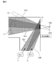
- FIG. 1 is a schematic configuration diagram of a structure in which a wireless transmission system is installed.
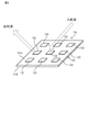
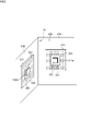
- FIG. 2 is a perspective view of the reflect array reflector.
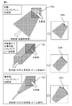
- FIG. 3 is an explanatory diagram of variations of reflected waves in the reflect array reflector.
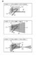
- FIG. 4 is a perspective view of a reflection unit having a protective cover.
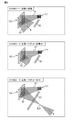
- FIG. 5 is a plan view showing an installation example of the reflection unit.
- FIG. 6 is a perspective view of a reflection unit having a protective cover.
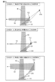
- FIG. 7 is an explanatory diagram showing variations of the reflection unit.
- FIG. 8 is an explanatory diagram showing variations of the reflection unit.
- FIG. 9 is an explanatory diagram showing variations of the reflection unit.
- FIG. 10 is an explanatory diagram showing variations of the reflection unit.
- FIG. 10 is an explanatory diagram showing variations of the reflection unit.
- FIG. 11 is an explanatory diagram showing variations of the reflection unit.
- FIG. 12 is an explanatory diagram of a single focus reflect array reflector.
- FIG. 13 is an explanatory diagram of a single focus reflect array reflector.
- FIG. 14 is an explanatory diagram of a multifocal reflect array reflector.
- FIG. 15 is an explanatory diagram of a multifocal reflect array reflector.
- FIG. 16 is a plan view showing an installation example of a flat metal reflector.
- FIG. 17 is a plan view showing an installation example of a convex curved metal reflector.
- FIG. 18 is a plan view showing an installation example of the reflect array reflector.
- FIG. 19 is a plan view showing an installation example of the reflect array reflector.
- FIG. 19 is a plan view showing an installation example of the reflect array reflector.
- FIG. 20 is a plan view showing an installation example of the reflect array reflector.
- FIG. 21 is a plan view showing an installation example of the reflect array reflector.
- FIG. 22 is a cross-sectional view showing an installation example of the reflect array reflector.
- FIG. 23 is an explanatory diagram showing that the transmission loss of radio waves on the ceiling or wall is large.
- FIG. 24 is a plan view showing an installation example of the reflect array reflector.
- FIG. 25 is a plan view showing an installation example of the reflect array reflector.
- FIG. 26 is a plan view showing an installation example of the reflect array reflector.
- FIG. 27 is a plan view showing an installation example of the reflect array reflector.
- FIG. 28 is a plan view showing an installation example of the reflect array reflector.
- FIG. 21 is a plan view showing an installation example of the reflect array reflector.
- FIG. 22 is a cross-sectional view showing an installation example of the reflect array reflector.
- FIG. 23 is an explanatory diagram showing that
- FIG. 29 is a plan view showing an installation example of the reflect array reflector.
- FIG. 30 is a plan view showing an installation example of the reflect array reflector.
- FIG. 31 is a plan view showing an installation example of the reflect array reflector.
- FIG. 32 is a plan view showing an installation example of the reflect array reflector.
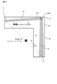
- FIG. 33 is a diagram showing an example of the configuration of the reflection unit according to the second embodiment.
- FIG. 34 is a diagram illustrating the reflection of the radio communication signal by the reflection unit according to the second embodiment.
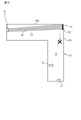
- FIG. 35 is a diagram illustrating reflection of a wireless communication signal by the reflection unit according to the second embodiment.
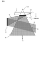
- FIG. 36 is a diagram for explaining the reflection of the radio communication signal by the first reflect array reflector according to the second embodiment.
- FIG. 37 is a diagram showing a configuration of a first modification of the reflection unit according to the second embodiment.
- FIG. 38 is a diagram showing a configuration of a second modification of the reflection unit according to the second embodiment.
- the reflection unit according to the embodiment is described above in order to change the direction of a radio transmission line between a first radio that transmits at least a radio communication signal and a second radio that receives at least the radio communication signal. Installed in a wireless transmission line.
- the reflection unit includes a plurality of reflectors for reflecting the radio communication signal.
- the plurality of reflectors have at least one or more reflect array reflectors.
- a reflect array reflector can be designed to radiate reflected waves in a desired direction, which is advantageous. Therefore, having the plurality of reflectors having at least one reflect array reflector increases the degree of freedom in the direction of the reflected wave.
- the "radio communication signal" referred to here includes a quasi-millimeter wave, a millimeter wave, a radio signal having a frequency higher than that of the millimeter wave, and a high-frequency power signal.
- the at least one or more reflect array reflectors may be a plurality of reflect array reflectors. By combining multiple reflect array reflectors, the function of the reflection unit is improved.
- the reflection unit may be attached to a structure having a corner where the first surface and the second surface are in contact with each other.
- the plurality of reflect array reflectors may include a first reflect array reflector attached to the first surface and a second reflect array reflector attached to the second surface. In this case, an appropriate installation form at the corner can be obtained.
- the plurality of reflect array reflectors may have at least one non-diffuse reflect array reflector configured so that the radio communication signal is non-diffuse reflected. In this case, a reflected wave of non-diffuse reflection is obtained.
- the plurality of reflect array reflectors are configured such that at least one diffuse reflect array reflector configured to diffusely reflect the radio communication signal and the radio communication signal to diffusely reflect. , With at least one non-diffuse reflect array reflector. In this case, diffuse and non-diffusive reflected waves are obtained.
- the at least one non-diffusion reflect array reflector may have at least one centralized reflect array reflector configured so that the reflected wave of the radio communication signal is concentrated at the focal point. In this case, the reflected wave can be narrowed.
- the reflection unit may be attached to a structure having a first portion and a second portion in which the radio communication signal is more easily propagated than the first portion.
- the centralized reflect array reflector may be attached to the structure so that the reflected wave passes through the second portion. In this case, the narrowed reflected wave can pass through the second portion.
- the centralized reflect array reflector may be configured such that the focal point is located at a position avoiding obstacles existing in the radio transmission line. In this case, the wireless communication signal can be transmitted while avoiding obstacles.
- the plurality of reflectors may have another reflector that further reflects the reflected wave of the centralized reflect array reflector.
- the other reflector may be smaller than the centralized reflect array reflector. In this case, it is possible to reduce the size of other reflectors.
- the plurality of reflect array reflectors include a first reflect array reflector and a second reflect array reflector that reflects the reflected wave of the radio communication signal by the first reflect array reflector. May be good.
- the first reflect array reflector may be one of a diffuse reflect array reflector, a centralized reflect array reflector, and a non-diffusive and non-concentrated reflect array reflector.
- the second reflect array reflector may be any one of the diffuse reflect array reflector, the centralized reflect array reflector, and the non-diffusive and non-concentrated reflect array reflector.
- the diffuse reflect array reflector may be a reflect array reflector configured to diffusely reflect the radio communication signal.
- the centralized reflect array reflector may be a reflect array reflector configured so that the reflected wave of the radio communication signal is concentrated at the focal point.
- the non-diffuse and non-concentrated reflect array reflector may be a reflect array reflector configured so that the radio communication signal is diffusely reflected and the reflected wave of the radio communication signal is not concentrated at the focal point.
- the reflection unit may be attached to a structure having an installation surface.
- the plurality of reflect array reflectors form a first reflected array reflector that forms a first reflected wave by reflecting the radio communication signal, and a second reflected wave by reflecting the first reflected wave. It may have a second reflect array reflector.
- the second reflect array reflector may be configured to radiate the second reflected wave in a range including a direction orthogonal to the installation surface. In this case, the second reflecting surface can be radiated to a range including a direction orthogonal to the installation surface, and an intuitively easy-to-understand radiation range can be obtained.
- the plurality of reflect array reflectors can include a first reflect array reflector, a second reflect array reflector, and a third reflect array reflector.
- the first reflect array reflector reflects a first incident wave having a first incident angle and heads toward the second reflect array reflector, and a second incident angle different from the first incident angle. It may be configured to reflect the second incident wave having a second incident wave and form a second reflected wave toward the third reflect array reflector.
- the second reflect array reflector may be configured to form a third reflected wave by reflecting the first reflected wave.
- the third reflect array reflector may be configured to form a fourth reflected wave by reflecting the second reflected wave.
- the third reflected wave and the fourth reflected wave may have radiation ranges overlapping with each other. In this case, the overlapping radiation range of the third reflected wave and the fourth reflected wave can be widened, which is preferable.
- the plurality of reflect array reflectors can include a first reflect array reflector and a second reflect array reflector.
- the reflection unit may further include a radio wave absorber.
- the first reflect array reflector reflects a first incident wave having a first incident angle and heads toward the second reflect array reflector, and a second incident angle different from the first incident angle. It may be configured to reflect the second incident wave having a second incident wave and form a second reflected wave toward the radio wave absorber. In this case, the second reflected wave can be absorbed.
- the at least one or more reflect array reflectors may have a multifocal reflect array reflector.
- the multifocal reflect array reflector has a first focus on a first radiation plane included in the radiation range of the reflected wave of the radio communication signal and a second focus on a second radiation surface orthogonal to the first radiation plane. May be configured to be in different positions. In this case, multiple focal points are obtained.
- the plurality of reflect array reflectors may include a first reflect array reflector and a second reflect array reflector.
- the first reflect array reflector may be configured to reflect the second reflected wave of the second radio communication signal transmitted from the second radio by the second reflect array reflector.
- the second reflect array reflector may be configured to reflect the first reflected wave of the first radio communication signal transmitted from the first radio by the first reflect array reflector.
- the first reflect array reflector includes a first concentrated reflecting unit configured to concentrate the first reflected wave at a focal point, and a first non-concentrated reflecting unit configured to prevent the first reflected wave from concentrating. May include.
- the second reflect array reflector includes a second concentrated reflecting unit configured to concentrate the second reflected wave at the focal point, and a second non-concentrated reflecting unit configured to prevent the second reflected wave from concentrating. May include. It is possible to reduce the transmission loss of the radio communication signal not only in the radio transmission line from the first radio to the second radio but also in the radio transmission line from the second radio to the first radio.
- Each of the first concentrated reflection unit and the second concentrated reflection unit may be configured by a reflect array including a plurality of reflecting elements. This increases the degree of freedom in the direction of the reflected wave. Further, since the reflect array can be configured in a flat plate shape, it is possible to save space and prevent the appearance of the mounting portion of the reflection unit from being spoiled.
- the first non-concentrated reflection unit may be configured to reflect the second reflected wave by the second concentrated reflection unit.
- the second non-concentrated reflection unit may be configured to reflect the first reflected wave by the first concentrated reflection unit.
- the first reflect array reflector may include a first low reflection region around the first non-concentrated reflection portion.
- the first low reflection region may have a reflectance lower than the reflectance of the second reflected wave by the first non-concentrated reflection unit.
- the second reflect array reflector may include a second low reflection region around the second non-concentrated reflection portion.
- the second low reflection region may have a reflectance lower than the reflectance of the first reflected wave by the second non-concentrated reflection portion. This makes it possible to prevent noise radio waves from being mixed into the wireless communication signal.
- Each of the first low reflection region and the second low reflection region may include a radio wave absorber. As a result, it is possible to further suppress the mixing of noise radio waves in the wireless communication signal.
- the first concentrated reflection unit may be configured in an annular shape.
- the first non-concentrated reflection unit may be arranged inside the first concentrated reflection unit.
- the second concentrated reflection unit may be configured in an annular shape.
- the second non-concentrated reflection unit may be arranged inside the second concentrated reflection unit.
- the reflection unit may be attached to a structure having a corner where the first surface and the second surface are in contact with each other.
- the first reflect array reflector may be attached to the first surface.
- the second reflect array reflector may be attached to the second surface.
- the first non-concentrated reflection unit may be arranged at a position closer to the second surface than the first concentrated reflection unit, or at a position away from the second surface from the first concentrated reflection unit.
- the second non-concentrated reflection unit may be arranged at a position closer to the first surface than the second concentrated reflection unit, or at a position away from the first surface from the second concentrated reflection unit.
- the arrangement of the first concentrated reflection unit and the first non-concentrated reflection unit, and the second concentrated reflection unit and the second non-concentrated reflection unit is determined according to the radio wave condition in the space where the reflection unit is attached. Therefore, the influence of noise in wireless communication can be reduced.
- the first non-concentrated reflection unit may be configured so that the first reflected wave is diffused, or the first reflected wave may be configured not to be diffused and not concentrated.
- the second non-concentrated reflection unit may be configured so that the second reflected wave is diffused, or the second reflected wave may be configured not to be diffused and not concentrated. Thereby, the wireless communication signal can be suitably transmitted.
- Each of the first non-concentrated reflecting unit and the second non-concentrated reflecting unit may be configured by a reflect array including a plurality of reflecting elements. This increases the degree of freedom in the direction of the reflected wave. Further, since the reflect array can be configured in a flat plate shape, it is possible to save space and prevent the appearance of the mounting portion of the reflection unit from being spoiled.
- the first non-concentrated reflection unit may be detachable from the first concentrated reflection unit.
- the second non-concentrated reflection unit may be detachable from the second concentrated reflection unit.
- the position of the first non-concentrated reflection unit can be adjusted to a position where the reflected wave from the second concentrated reflection unit can be incident.
- the position of the second non-concentrated reflection unit can be adjusted to a position where the reflected wave from the first concentrated reflection unit can be incident.
- the reflection unit may be embedded in a building material.
- the preferred form is obtained in which the reflective unit is embedded in the building material.
- the reflection unit according to the embodiment is installed in a radio transmission line between a first radio that transmits at least a radio communication signal and a second radio that receives at least the radio communication signal.
- the reflection unit comprises at least one centralized reflect array reflector configured such that the reflected waves of the radio communication signal are focused at the focal point. In this case, the reflected wave can be narrowed.
- the reflection unit may be attached to a structure having a first portion and a second portion in which the radio communication signal is more easily propagated than the first portion.
- the centralized reflect array reflector may be attached to the structure so that the reflected wave passes through the second portion. In this case, the narrowed reflected wave can pass through the second portion.
- the centralized reflect array reflector may be configured such that the focal point is located at a position avoiding obstacles existing in the radio transmission line. In this case, obstacles can be avoided.
- the reflection unit may further include another reflector that further reflects the reflected wave.
- the other reflector may be smaller than the centralized reflect array reflector. In this case, it is possible to reduce the size of other reflectors.
- the wireless transmission unit includes a first radio that transmits at least a radio communication signal, a second radio that receives at least the radio communication signal, the first radio, and the second radio. It is provided with a reflection unit installed in the wireless transmission path in order to change the direction of the wireless transmission path between the and.
- FIG. 1 shows a wireless transmission system 1 according to the first embodiment.
- the wireless transmission system 1 according to the first embodiment is used, for example, for wireless transmission having a frequency higher than quasi-millimeter wave and quasi-millimeter wave, and more preferably used for wireless transmission having a frequency higher than millimeter wave and millimeter wave.
- Millimeter waves are radio waves from 30 GHz to 300 GHz.
- a quasi-millimeter wave is a radio wave whose frequency is lower than that of a millimeter wave but is close to that of a millimeter wave.
- the frequency of the quasi-millimeter wave is, for example, 20 GHz or more and less than 30 GHz.
- High-frequency radio waves such as millimeter waves can increase the capacity of transmitted data.
- high-frequency radio waves such as millimeter waves have high straightness and tend to have narrow directivity (narrow beam property) in order to cover transmission loss. Therefore, high-frequency radio waves such as millimeter waves have a problem in radiating into a space with poor visibility or radiating into a wide range. In addition, high-frequency radio waves such as millimeter waves are difficult to pass through members such as walls, so there is a problem with indoor transmission.
- the wireless transmission system 1 shown in FIG. 1 includes a plurality of radios 10 and 20 for transmitting and receiving wireless communication signals.
- the plurality of radios 10 and 20 include a first radio 10 and a second radio 20.
- the first radio 10 is, for example, a base station (Base Station).
- the base station 10 is, for example, a 5th generation or later generation mobile communication system base station.
- the second radio 20 is, for example, a user terminal (User Equipment) that communicates with the base station 10.
- the user terminal 20 may be a mobile station that is mobile or a fixed station that does not move.
- the wireless transmission system 1 shown in FIG. 1 is installed in a structure 30 having an internal space such as a building.
- a building is, for example, a house, a building, or a factory.
- the structure 30 may be an underground mall, a tunnel, or the like.
- the internal space of the structure 30 is used as a radio transmission line.
- the space used as a radio transmission line may be an external space surrounded by one or a plurality of buildings.
- the structure 30 shown in FIG. 1 is, for example, a building having a plurality of internal spaces S1, S2, and S3 partitioned by a wall material 41.
- the plurality of interior spaces include, for example, a corridor S1 and a room S2.
- the ceiling material 42 and the floor material 43 together with the wall material 41 define the internal spaces S1, S2, and S3 in the building 30.
- the building 30 has, as an internal space, an under-ceiling space S3 which is an upper space of the ceiling material 42, or an underfloor space which is a lower space of the floor material 43.
- the ceiling space S3 or the underfloor space which is not the internal space utilized by the person is also used as the radio transmission path.
- the wireless transmission system 1 shown in FIG. 1 includes a plurality of reflection units 100A, 100B, 100C, 100D, 100E, 100F, 100G.
- the plurality of reflection units 100A, 100B, 100C, 100D, 100E, 100F, 100G are in the radio transmission line in order to change the direction of the radio transmission line between the base station 10 and the user terminals 20A, 20B, 20C, respectively. Will be installed in.
- the reflection unit 100A is provided in the line of sight (Line of Site; LOS) of the base station 10 and reflects the radio communication signal (incident wave) transmitted from the base station 10.
- the reflected wave by the reflection unit 100A is radiated to the user terminal 20A located outside the line of sight (No Line of Sign; NLOS) of the base station 10.
- the reflection unit 100A diffuses the incident wave transmitted from the base station 10 and radiates the reflected wave of the wide beam to the space where the user terminal 20A is located. Since the reflection unit 100A is capable of wide-angle reflection by diffusion, it can supplement the narrow beam property in high-frequency radio waves such as millimeter waves.
- the reflection unit 100B is provided within the line of sight of the base station 10 and reflects the radio communication signal (incident wave) transmitted from the base station 10.
- the reflection unit 100B allows radio waves to pass from the internal space S1 in which the base station 10 is present to the adjacent internal space S2 partitioned by the wall material 41 through an opening formed in the wall material 41.
- the reflection unit 100C further reflects the reflected wave by the reflection unit 100B. In the internal space S2, the reflected wave by the reflection unit 100C is radiated toward the reflection unit 100D.
- the reflection unit 100D further reflects the reflected wave by the reflection unit 100C and gives it to the user terminal 20B.
- radio waves such as millimeter waves may not be sufficiently radiated to another space S2 partitioned by a building material such as the wall material 41, but in the reflection unit 100B, the radio waves open the opening of the wall material 41. Since the radio waves are reflected so as to pass through, the radio waves can be efficiently radiated to another space S2.
- the reflection unit 100E is provided within the line of sight of the base station 10 and reflects the radio communication signal (incident wave) transmitted from the base station 10.
- the reflection unit 100E allows radio waves to pass from the internal space S1 in which the base station 10 is present to the ceiling space S3 through the opening formed in the ceiling material 42.
- the reflection unit 100F further radiates the reflected wave by the reflection unit 100E.
- the reflected wave by the reflection unit 100F is radiated toward the reflection unit 100G.
- the reflection unit 100G further reflects the reflected wave from the reflection unit 100F and gives it to the user terminal 20C.
- even a space that is not used by humans, such as the attic space S3, is used as a radio transmission line.
- radio waves can be radiated to every corner of the room.
- the reflection units 100A, 100B, 100C, 100D, 100E, 100F, 100G also reflect wireless communication signals (radio waves) transmitted from the user terminals 20A, 20B, 20C to the base station 10.
- the functions of the reflection units 100A, 100B, 100C, 100D, 100E, 100F, and 100G shown in FIG. 1 are only examples. In the following, the details of the reflection unit and various variations of its functions will be described.
- FIG. 2 shows the reflect array reflector 110 included in the reflection unit according to the first embodiment. Since the reflect array reflector 110 of the first embodiment has a plate shape, it is also called a reflect array reflector.
- the reflection unit according to the first embodiment includes one or more reflect array reflectors 110.
- the reflect array reflector 110 includes a high frequency substrate 131 having a first surface, which is the front surface 131A, and a second surface, which is the back surface 131B.
- the high frequency substrate 131 is formed in a flat plate shape.
- the high frequency substrate 131 is made of a dielectric.
- a plurality of reflective elements 132, each of which is a conductor, are formed on the front surface 131A of the high-frequency substrate 131.
- a conductor serving as a ground is formed on the back surface 131B of the high-frequency substrate 131.
- the reflect array reflector 110 reflects radio waves on the front surface 131A on which the reflecting element 132 is formed.
- a radio wave reflector for example, there is a flat metal reflector.
- the reflect array reflector 110 can radiate a reflected wave in a desired direction by adjusting the size or shape of the reflecting element 132.
- the reflect array is generally used as a part of the antenna.
- the reflect array reflector 110 of the first embodiment does not form a part of the antenna included in the radios 10 and 20, but is a radio wave (radio communication signal) radiated from the radios 10 and 20 provided with the antenna. Is used to reflect in the radio transmission path. That is, the reflect array reflector 110 of the first embodiment is installed in the radio transmission line in order to change the direction of the radio transmission line between the first radio device 10 and the second radio device 20.
- the reflect array reflector 110 can be designed to simulate the reflection characteristics of a metal reflecting surface having an arbitrary shape with respect to the diffusion or concentration of the reflected wave.
- the reflect array reflector 110 that simulates the reflection characteristics of a metal reflective surface of an arbitrary shape.
- the reflective element 132 of the reflect array reflector 110 from the reflection characteristics of the metal reflective surface to be simulated. Find the amount of phase change to be done. There is a predetermined correspondence between the amount of phase change and the reflecting element 132. Therefore, once the amount of phase change is obtained, the size or shape of the reflecting element 132 can be determined.
- the reflection characteristics simulated by the reflect array reflector 110 need only be the reflection characteristics related to the diffusion or concentration of the reflected waves on the metal reflecting surface, and it is not necessary to simulate the direction of the reflected waves.
- the direction of the reflected wave cannot be freely adjusted, but the reflect array reflector 110 can be in a desired direction by appropriately designing the size or shape of the reflecting element. Can radiate reflected waves to.
- the shape of the metal reflecting surface on which the reflect array reflector 110 can simulate the reflection characteristics is, for example, a spherical surface.
- the convex curved metal plate 200A having the convex curved surface forming a part of the spherical surface diffuses the reflected wave.
- the degree of diffusion is determined by the curvature of the convex curved surface.
- the shape of another metal reflecting surface on which the reflect array reflector 110 can simulate the reflection characteristics is a rotating paraboloid.
- the concave curved metal plate 200C having a concave curved surface forming a part of the rotating paraboloid concentrates the reflected wave.
- the degree of concentration is determined by the curvature of the concave curved surface.
- the focal point of the concentrated reflected wave is located in front of the concave curved metal plate 200C.
- the flat metal plate 200B does not have the function of diffusing or concentrating the reflected wave.
- the reflect array reflector that simulates the beam diffusion characteristics of the convex curved metal plate 200A is referred to as a diffusion reflect array reflector 110A.
- the diffuse reflect array reflector 110A diffuses the reflected wave in the same manner as the convex curved metal plate 200A.
- the wave reflected by the diffuse reflect array reflector 110A is also referred to as a diffuse reflected wave.
- a reflect array reflector that simulates the beam characteristics of a flat metal plate 200B is called a non-diffusing and non-concentrated reflect array reflector 110B.
- the non-diffusing and non-concentrating reflect array reflector 110B does not have the function of diffusing or concentrating the reflected wave, like the flat metal plate 200B.
- a reflect array reflector that simulates the beam concentration characteristics of a concave curved metal plate 200C is called a centralized reflect array reflector 110C.
- the centralized reflect array reflector 110C concentrates the reflected wave in the same manner as the concave curved metal plate 200C.
- the focal point of the concentrated reflected wave is located in front of the centralized reflect array reflector 110C.
- the non-diffusive and non-concentrated reflect array reflector 110B and the centralized reflect array reflector 110C are also referred to as non-diffusive and non-diffusive reflect array reflectors.
- the reflected wave by the non-diffuse reflect array reflectors 110B and 110C is also referred to as a spot reflected wave or a non-diffuse reflected wave.
- the reflected wave by the non-diffusing and non-concentrated reflect array reflector 110B is also referred to as a non-concentrated spot reflected wave.
- the reflected wave by the centralized reflect array reflector 110C is also referred to as a concentrated spot reflected wave.
- the reflect array reflector 110 can diffuse or concentrate reflected waves without forming a convex curved surface or a concave curved surface like a metal reflector. If a convex or concave curved surface is required, the space required for installation increases, but in the case of the reflect array reflector 110, the reflected wave can be diffused or concentrated on a flat surface, so that the space required for installation is increased. Can be made smaller.
- the metal reflecting surface simulated by the diffuse reflect array reflector 110A and the centralized reflect array reflector 110C is one of a curved surface of a part of a spherical surface which is the surface of a sphere and a rotating paraboloid which is the surface of a rotating paraboloid.
- the surface is not limited to the curved surface of the portion, and may be a curved surface of a part of the surface of a spheroid or a paraboloid.
- the rotating release object includes a spheroid and a rotating hyperboloid as one form thereof.
- the metal reflective surface simulated by the diffuse reflect array reflector 110A and the centralized reflect array reflector 110C may be a curved surface of a part of the surface of a spheroid or a spheroid.
- the convex curved metal plate 200A shown in FIG. 3 is a rotating paraboloid or a spheroid, and the reflect array reflector 110A simulates the beam diffusion characteristics of the convex curved metal plate 200A, the focal point of the reflected wave is It is located behind the reflect array reflector 110A and the convex curved metal plate 200A.
- FIG. 4 shows an example of the reflection unit 100 according to the first embodiment.
- the reflection unit 100 shown in FIG. 4 includes one reflect array reflector 110 and a protective cover 120 (housing) surrounding the reflect array reflector 110.
- the protective cover 120 is a member that covers the reflect array reflector 110 so as not to be exposed.
- the reflection unit 100 according to the first embodiment is a passive element that only reflects radio waves, and does not have an active element (for example, a transmitter or a receiver) for transmitting or receiving radio waves.
- the reflection unit 100 according to the first embodiment reflects an incident wave incident from the first direction in a second direction different from the first direction.
- FIG. 5 shows another example of the reflection unit 100 according to the first embodiment.
- the reflection unit 100 according to the first embodiment is installed at a position where the direction of the radio transmission line is to be changed.
- the place where the direction of the radio transmission line is to be changed is, for example, a corner 31 in which the first surface 31A and the second surface 31B are in contact with each other in the building 30.
- the reflection unit 100 shown in FIG. 5 includes a first reflect array reflector 111 and a second reflect array reflector 112.
- the first reflect array reflector 111 reflects the incident wave 60 along the second surface 31B to form a reflected wave 61 toward the second reflect array reflector 112.
- the second reflect array reflector 112 reflects the reflected wave 61 to form the reflected wave 62 along the first surface 31A.
- the first reflect array reflector 111 is covered with a protective cover 120.
- the protective cover 120 including the first reflect array reflector 111 is embedded in the wall material 41A.
- the first reflect array reflector 111 may be attached to the wall material 41A together with the protective cover 120 after the wall material 41A is assembled as the building 30. Further, the first reflect array reflector 111 may be attached to the wall material 41A together with the protective cover 120 before the wall material 41A is assembled as the building 30.
- the first reflect array reflector 111 is installed in parallel with the first surface 31A, which is the surface of the wall material 41A. Further, since the first reflect array reflector 111 is embedded inside the wall material 41A, the appearance of the wall material 41A is less likely to be impaired. Further, the protective cover 120 also has little or no protrusion from the wall material 41A, so that the appearance of the wall material 41A is less likely to be impaired.
- the second reflect array reflector 112 is covered with a protective cover 120.
- the first reflect array reflector 111 and the second reflect array reflector 112 are covered by different protective covers 120, but they may be covered by the same protective cover 120.
- the protective cover 120 containing the second reflect array reflector 112 is embedded in the wall material 41B.
- the second reflect array reflector 112 may be attached to the wall material 41B together with the protective cover 120 after the wall material 41B is assembled as the building 30. Further, the second reflect array reflector 112 may be attached to the wall material 41B together with the protective cover 120 before the wall material 41B is assembled as the building 30.
- the second reflect array reflector 112 is installed in parallel with the second surface 31B, which is the surface of the wall material 41B. Further, since the second reflect array reflector 112 is embedded inside the wall material 41B, the appearance of the wall material 41B is less likely to be impaired. Further, the protective cover 120 also has little or no protrusion from the wall material 41B, so that the appearance of the wall material 41B is less likely to be impaired.
- the reflection unit 100 shown in FIG. 5 has the incident wave 60 in a direction parallel to the first surface 31A in a radio transmission path in which the incident wave 60 is radiated in a direction parallel to the second surface 31B (first direction). It is reflected in (second direction) to generate a reflected wave 62.
- the reflection unit 100 shown in FIG. 5 forms a radio transmission line along the wall materials 41A and 41B by bending the radio transmission line by 90 degrees at the corner 31.
- both the reflection unit 100 shown in FIG. 4 and the reflection unit 100 shown in FIG. 5 have a common function of bending the radio transmission line by 90 degrees.
- FIG. 4 if only one reflect array reflector 110 is used, it is difficult to install the reflect array reflector 110 in parallel with the wall materials 41A and 41B. Therefore, as shown in FIG. 5, it is advantageous to use a plurality of reflect array reflectors 111 and 112.
- the reflection unit 100 may include a plurality of reflect array reflectors 111 and 112 in one protective cover 120.
- the reflection unit 100 preferably has a plurality of reflectors 110 including at least one reflect array reflector 110.
- the plurality of reflectors 110 may all be reflect array reflectors 110. Further, the plurality of reflectors 110 may have one or more reflect array reflectors 110A, 110B, 110C and one or more metal reflectors 200A, 200B, 200C.
- one reflection unit 100 does not have to be configured as one cohesive structure as shown in FIG. 4 or FIG. 6, and a plurality of reflection units 100 do not need to be configured as one cohesive structure as shown in FIG. It may be configured as a separated structure.
- one reflection unit 100 refers to a cohesive unit that realizes a desired predetermined reflection angle at a place where the reflection unit 100 is installed.
- the reflection unit 100 shown in FIG. 5 is configured as a plurality of separated structures.
- the reflection unit 100 shown in FIG. 6 is configured as one composite structure.
- both of the reflection units 100 shown in FIGS. 5 and 6 realize the desired reflection angle of 90 degrees at the corner 31 of 90 degrees. Therefore, in each of FIGS. 5 and 6, the number of reflection units 100 is one.
- FIG. 7 shows CASE 1-1, 1-2, 1-3 in which the first reflect array reflector 111 is a non-diffusing and non-concentrated reflect array reflector 110B that forms a decentralized spot reflected wave.
- the second reflect array reflector 112 is also a non-diffusing and non-concentrated reflect array reflector 110B.
- CASE 1-1 only the conversion of the direction of the radio transmission line is mainly performed.
- the second reflect array reflector 112 is a diffuse reflect array reflector 110A.
- the second reflected wave 62 can be made into a wide-angle beam.
- the second reflect array reflector 112 is a centralized reflect array reflector 110C. In CASE 1-3, it is possible to concentrate the second reflected wave 62 and to make a wide-angle beam of the second reflected wave 62 beyond the focal point 62A.
- FIG. 8 shows CASE2-1, 2, 2-3, in which the first reflect array reflector 111 is a diffuse reflect array reflector 110A that forms a diffuse reflected wave.
- the second reflect array reflector 112 is also a diffuse reflect array reflector 110A.
- the first reflect array reflector 111 can be miniaturized. Even if the first reflect array reflector 111 is miniaturized, the first reflected wave 61 is diffused to form a wide-angle beam. Moreover, since the second reflect array reflector 112 is further diffusely reflected, the beam is further widened.
- the second reflect array reflector 112 is a non-diffusing and non-concentrated reflect array reflector 110B. Also in CASE2-2, the size of the first reflect array reflector 111 can be reduced.
- the second reflect array reflector 112 is a centralized reflect array reflector 110C. Also in CASE2-3, the size of the first reflect array reflector 111 can be reduced. Further, in CASE 2-3, it is possible to concentrate the second reflected wave 62 and to make a wide-angle beam of the second reflected wave 62 beyond the focal point 62A.
- FIG. 9 shows CASE 3-1, 3-2, 3-3 in which the first reflect array reflector 111 is a centralized reflect array reflector 110C that forms a concentrated reflected wave.
- the second reflect array reflector 112 is also a centralized reflect array reflector 110C.
- the first reflected wave 61 is concentrated at the focal point 61A and the second reflected wave 62 is concentrated at the focal point 62A.
- the second reflect array reflector 112 is a non-diffusing and non-concentrated reflect array reflector 110B.
- the first reflected wave 61 is concentrated at the focal point 61A.
- the second reflect array reflector 112 is a diffuse reflect array reflector 110A.
- the first reflected wave 61 is concentrated at the focal point 61A. Further, the second reflected wave 62 can be made into a wide-angle beam.
- each focal point 61A of the first reflected wave 61 exists between the first reflect array reflector 111 and the second reflect array reflector 112.
- the position of each focal point 61A shown in FIG. 9 is not limited to between the first reflect array reflector 111 and the second reflect array reflector 112, and CASE 4-1 and 4-2, 4-3 shown in FIG. 10 are not limited. It may be the position shown in any of.
- the focal point 61A is located farther than the second reflect array reflector 112 when viewed from the first reflect array reflector 111. That is, the second reflect array reflector 112 exists between the first reflect array reflector 111 and the focal point 61A.
- the second reflect array reflector 112 since the second reflect array reflector 112 only needs to reflect the narrowed first reflected wave 61, the second reflect array reflector 112 can be miniaturized. Further, in the case of CASE4-1, the electric field strength of the first reflected wave 61 reflected by the second reflect array reflector 112 can be increased.
- the focal point 61A exists on the second reflect array reflector 112 or in the vicinity of the second reflect array reflector 112.
- the second reflect array reflector 112 since the second reflect array reflector 112 only needs to reflect the first reflected wave 61 concentrated at the focal point 61A, the second reflect array reflector 112 can be made very small.
- the electric field strength of the first reflected wave 61 reflected by the second reflect array reflector 112 can be made very large.
- the focal point 61A exists between the first reflect array reflector 111 and the second reflect array reflector 112. That is, the second reflect array reflector 112 is located farther than the focal point 61A when viewed from the first reflect array reflector 111.
- the beam can be concentrated between the first reflect array reflector 111 and the second reflect array reflector 112.
- the reflected wave 61 is efficiently transmitted in a small-diameter space (such as an opening formed in a wall or ceiling) existing between the first reflect array reflector 111 and the second reflect array reflector 112. be able to. Further, the reflected wave 61 can be transmitted while avoiding obstacles existing between the first reflect array reflector 111 and the second reflect array reflector 112.
- FIG. 11 shows CASE 5-1, 5-2 as an example in which the reflection unit 100 is used as a penetration unit for passing radio waves through a small diameter opening 50 formed in the wall material 41.
- CASE 5-1 corresponds to, for example, an example in which the second reflected wave 62 in CASE 1-3, CASE 2-3, CASE 3-1 passes through the opening 50. Since the second reflected wave 62 is concentrated and reduced in diameter at the focal point 62A, it can pass through a small opening 50 formed in a building material such as the wall material 41. The diameter of the second reflected wave 62 is smaller than that of the opening 50 at the position of the opening 50. Therefore, the second reflected wave 62 is prevented from being obstructed by a building material such as the wall material 41, and can efficiently pass at the position of the opening 50.
- CASE 5-2 corresponds to, for example, an example in which the first reflected wave 61 in CASE 3-1 or CASE 4-3 passes through the opening 50.
- CASE 5-2 may be regarded as an example in which the reflected wave of the reflect array reflector 110 shown in FIG. 4 passes through the opening 50.
- the above-mentioned centralized reflect array reflector 110C may be a single focus reflect array reflector 110C-1 (see FIGS. 12 and 13) or a multifocal reflect reflector. It may be an array reflector 110C-2 (see FIGS. 14 and 15).
- the single focus reflect array reflector 110C-1 is configured so that there is only one focal point of the reflected wave.
- the multifocal reflect array reflector 110C-2 is configured to have a plurality of focal points.
- FIG. 12 shows the spread of the reflected wave beyond the focal point 65 in the case of the single focal point reflect array reflector 110C-1.
- the relationship between the spread ⁇ of the reflected wave on the horizontal plane (first radiation plane) included in the radiation range of the reflected wave and the spread ⁇ of the reflected wave on the vertical plane (second radiation plane) is a single focal point reflect. It is constrained by the aspect ratio of the array reflector 110C-1. Therefore, it is necessary to change the size or aspect ratio of the second reflect array reflector 112 that further reflects the reflected wave by the single focus reflect array reflector 110C-1 according to the arrangement thereof.
- the size (horizontal dimension) of the second reflect array reflector 112 coincides with the spread ⁇ of the reflected wave in the horizontal plane, but the size of the second reflect array reflector 112. (Vertical dimension) may be smaller than the spread ⁇ of the reflected wave on the vertical plane. In this case, the second reflect array reflector 112 cannot receive all the reflected waves, and the transmission efficiency is lowered. Therefore, for efficient transmission, it is necessary to change the vertical dimension of the second reflect array reflector 112 according to the arrangement of the second reflect array reflector 112, which is uneconomical.
- the first focal point 65A in the horizontal plane (first radiation plane) included in the radiation range of the reflected wave and the radiation range of the reflected wave are included.
- the second focal point 65B on the vertical plane (second radial plane) exists at a different position.
- the horizontal plane (first radiation plane) is a plane including a horizontal line.
- the horizontal line here is a horizontal line that passes through the center of the front surface of the multifocal reflect array reflector 110C-2 and is along the front surface thereof.
- the vertical plane (second radial plane) includes vertical lines and is orthogonal to the horizontal plane (first radial plane).
- the vertical line here is a vertical line passing through the center of the front surface of the multifocal reflect array reflector 110C-2.
- the spread ( ⁇ , ⁇ ) of the reflected wave can be arbitrarily set regardless of the aspect ratio of the multifocal reflect array reflector 110C-2. Can be formed. For example, as shown in FIG. 15, the first focal point 65A on the horizontal plane is closer to the multifocal reflect array reflector 110C-2, and the second focal point 65B on the vertical plane is due to the second reflect array reflector 112. It can be set by shifting it to a closer position. As a result, an appropriate spread of the reflected wave can be controlled according to the aspect ratio and arrangement of the second reflect array reflector 112, which is economical.
- the amount of phase change of the reflecting element 132 for separating the first focal point 65A on the horizontal plane and the second focal point 65B on the vertical plane may be obtained as follows. That is, the first phase change amount of the reflecting element 132 in the horizontal plane in which the first focus 65A is set and the second phase change amount of the reflecting element 132 in the vertical plane in which the second focus 65B is set are obtained. Then, by adding the first phase change amount and the second phase change amount, the phase change amount of the reflecting element 132 necessary for designing the multifocal reflect array reflector 110C-2 can be obtained.
- a curved surface in which the first focal length 65A on the horizontal plane and the second focal length 65B on the vertical plane exist at different positions for example, the surface of a rotating radiation object having different focal lengths in the horizontal and vertical cross sections.
- FIG. 16 shows a wireless transmission system having a flat metal plate 200B as a reflector as a reference example.
- a wireless transmission system is constructed in a building 30 in which the first area 71 and the second area 72 are orthogonal to each other and have an L-shaped internal space as a whole.
- the wireless transmission system includes a base station 10 and user terminals 21 and 22.
- the base station 10 is installed in the first area 71. Since the user terminals 21 and 22 exist in the second area 72, they exist outside the line of sight (NLOS) when viewed from the base station 10.
- the flat metal plate 200B is installed at a corner 31 in contact with the wall material 41A facing the second area 72 and the wall material 41B facing the first area 71.
- the flat metal plate 200B bends the incident wave 60 that travels straight through the first area 71 along the wall material 41B by about 90 degrees to form a reflected wave 61 that travels straight through the second area 72 along the wall material 41A.
- the radio wave can reach the user terminal 21 which is out of sight.
- the radio wave has a narrow beam property, in the case of FIG. 16, the radio wave does not reach the user terminal 22 existing in the second area 72.
- FIG. 17 shows an example in which a convex curved metal plate 200A is installed in a corner 31 instead of the flat metal plate 200B of FIG.
- a wide-angle beam is formed by the convex curved metal plate 200A, and radio waves can be radiated to the entire second area 72.
- the reflect array reflector 110 instead of the metal plate as the reflector.
- the reflect array reflector 110 has a flat plate shape and can be designed to direct the reflected wave in a desired direction.
- the reflect array reflector 110 is parallel to the wall materials 41A and 41B, and the amount of protrusion from the wall materials 41 and 41B is small, so that the appearance is not impaired.
- the reflect array reflector 110 can direct the reflected wave in a desired direction, it is difficult to form the reflected wave when the incident wave enters from the side of the reflect array reflector 110. .. Therefore, the installation mode of FIG. 18 is not realistic. It is also difficult for the reflect array reflector 110 to radiate a reflected wave right beside it. Therefore, the installation form of FIG. 19 is also not realistic.
- the reflection unit 100 can appropriately reflect the incident wave 60 from the first area 71 to the second area 72.
- the first reflect array reflector 111 is attached to the first surface 31A of the wall material 41A facing the base station 10.
- the second reflect array reflector 112 is attached to the second surface 31B of the wall material 41B facing the user terminals 21 and 22.
- the first reflect array reflector 111 and the second reflect array reflector 112 are installed at the corner 31 where the first surface 31A and the second surface 31B are in contact with each other. It should be noted that the points not particularly described in FIG. 20 are the same as those in FIGS. 16 to 19.
- the first reflect array reflector 111 receives the incident wave 60 from substantially the front direction and forms the first reflected wave 61 toward the second reflect array reflector 112 which is diagonally forward (not right beside).
- the first reflect array reflector 111 is, for example, a centralized reflect array reflector 110C configured such that the focal point of the first reflected wave 61 is farther than the second reflect array reflector 112. Therefore, the second reflect array reflector 112 may be small. Further, the electric field strength of the radio wave received by the second reflect array reflector 112 becomes high.
- the second reflect array reflector 112 receives the first reflected wave 61 diagonally from the front and radiates the second reflected wave 62 substantially in the front direction.
- the second reflect array reflector 112 is, for example, a diffuse reflect array reflector 110A in which the focus of the second reflected wave 62 is behind the second reflect array reflector 112. Therefore, the second reflected wave 62 is converted into a wide-angle beam and reaches the entire second area 72.
- FIG. 20 has a better appearance than the installation form shown in FIG. 16 or FIG.
- a centralized reflect array reflector 110C is used instead of the diffuse reflect array reflector 110A.
- points not particularly described are the same as in FIG. 20.
- the second reflect array reflector 112 in FIG. 21 forms a second reflected wave 62 in which the focal point 62A exists in the vicinity of the obstacle 45.
- the obstacle 45 is, for example, a locker or other object installed so as to be in contact with the wall material 41.
- the radio wave does not reach a large range due to the obstacle 45. Become.
- the second reflex and the array reflector 112 can narrow the second reflected wave 62 at the focal point 62A near the obstacle 45, the beam avoids the obstacle 45. Can propagate.
- the second reflected wave 62 diffuses beyond the focal point 62A, it reaches substantially the entire second area 72.
- FIG. 22 shows an example in which a small-diameter opening 30B is formed in a building material such as a wall material 41 or a ceiling material 42 to transmit radio waves with a small transmission loss.
- FIG. 22 corresponds to CASE 5-2 shown in FIG.
- a high frequency radio wave 60A such as a millimeter wave is difficult to pass through a building material such as a wall material 41 or a ceiling material 42. That is, when the radio wave 60A hits a building material such as a wall material 41 or a ceiling material 42, most of the radio wave 60A becomes a reflected wave 67B, and the transmitted wave 67C is very small. Therefore, it is difficult to transmit the radio wave 60A to another space separated by a building material such as a wall material 41 or a ceiling material 42.
- a small-diameter opening 30B is formed in a building material such as a wall material 41 or a ceiling material 42.
- the opening 30B can transmit even a high frequency radio wave such as a millimeter wave with a small loss. That is, in the building material such as the wall material 41 or the ceiling material 42, the portion where the opening 30B is not formed is the first portion having a large transmission loss, and the portion where the opening 30B is formed has a small transmission loss. There are two parts.
- the second portion 30B is easier for radio waves to propagate than the first portion 30A.
- the reflect array reflector 110 is a centralized type, the diameter of the reflected wave 61 is made smaller than that of the second portion 30B at the position of the second portion 30B which is an opening. Therefore, it is possible to prevent the reflected wave 61 from being obstructed by a building material such as a wall material 41 or a ceiling material 42. As a result, the transmission loss is reduced.
- the reflect array reflector 110 is a decentralized type, an opening 30B having the same size as or larger than the reflect array reflector 110 is required to transmit radio waves with low loss.
- the opening 30B may be small. Therefore, the opening 30B is easy to form. Further, since the opening 30B may be small, it is possible to suppress the appearance from being spoiled.
- the opening 30B may be closed with a member such as a decorative plate 30C. Since the decorative board 30C is made of a material that is thinner than the wall material 41 or easily transmits radio waves, an increase in radio wave transmission loss can be suppressed.
- FIG. 24 shows an example in which reflectors 111 and 112 are installed at each of the plurality of corners 33 and 34 in the structure 30.
- the incident wave 60 is reflected by the reflector 111 to form a first reflected wave 61 traveling along the wall material 41A.
- the first reflected wave 61 is reflected by the reflector 111, and the second reflected wave 62 is formed.
- the reflectors 111 When transmitting radio waves using a plurality of reflectors 111 and 112, considering the stability of the reflective surface, ease of installation, inconspicuousness, and the like, the reflectors 111 are placed on each of the corners 33 and 34 of the structure 30. , 112 is appropriate. However, when the reflectors 111 and 112 are installed at the corners 33 and 34, the radio transmission line has no choice but to be close to the wall material 41A. In particular, a large clearance is required between the first reflected wave 61 and the wall material 41A at the center of the transmission node where the radio wave passage (first Fresnel radius) is maximized. As a result, it is necessary to install the reflectors 111 and 112 away from the wall material 41A.
- the reflectors 111 and 112 are configured to form a centralized reflected wave, and the focal point 61A is present near the center of the transmission node, so that the first reflected wave 61 and the wall material 41A are present. It is preferable because the clearance between the two can be reduced.
- the single reflectors 111 and 112 are installed in the corners 33 and 34, respectively, but the present invention is not limited to that.
- the reflection unit 100 according to the first embodiment may be installed in each of the corners 33 and 34, or the concave curved metal plate 200C may be installed.
- the reflection unit 100 installed in each of the corners 33 and 34 preferably includes a centralized reflect array reflector 110C. More specifically, the reflection unit 100 installed in each of the corners 33 and 34 is preferably any one of CASE 1-3, 2-3, 3-1.
- FIG. 26 shows a flat metal plate 200B installed on the wall material 41.
- the wall material 41 has an installation surface 47 of the flat metal plate 200B.
- the flat metal plate 200B may be installed in signage or digital signage.
- the radiation direction (reflection direction) of radio waves that is easy for humans to intuitively understand is the front direction of the reflector or the reflector installation surface 47. Therefore, as shown in FIG. 27, it is conceivable to install the reflect array reflector 110 on the installation surface 47.
- the reflect array reflector 110 of FIG. 27 is configured to radiate the reflected wave 61 in a range including the front direction which is the orthogonal direction of the installation surface 47. In the case of FIG. 27, since the reflected wave 61 is radiated in the front direction of the reflect array reflector 110 or the installation surface 47, it is easy to intuitively understand the radiation direction of the invisible reflected wave 61.
- the range X2 of the reflect array reflector 110 is smaller than the range X1 where the incident wave 60 hits the installation surface 47. .. As a result, the reflection efficiency of the reflect array reflector 110 is reduced.
- the decrease in reflection efficiency can be suppressed. That is, the incident wave 60 is reflected by the first reflect array reflector 111.
- the first reflected wave 61 by the first reflect array reflector 111 heads toward the second reflect array reflector 112 installed on the installation surface 47.
- the first reflect array reflector 111 can be installed so as to receive the incident wave 60 from substantially the front. Therefore, the first reflect array reflector 111 can efficiently receive the incident wave 60.
- the first reflect array reflector 111 is preferably a centralized reflect array reflector 110C.
- the first reflected wave 61 can be concentrated on the second reflect array reflector 112. Therefore, the second reflect array reflector 112 may be small.
- the focal point 61A of the first reflected wave 61 is located farther than the second reflect array reflector 112 when viewed from the first reflect array reflector 111.
- the second reflect array reflector 112 reflects the first reflected wave 61 and forms the second reflected wave 62 radiated in the front direction of the second reflect array reflector 112 or the installation surface 47. In the case of FIG. 28, it is easy to intuitively understand the radiation direction of the invisible second reflected wave 62.
- the second reflect array reflector 112 is preferably a diffuse reflect array reflector 110A.
- the second reflected wave 62 is radiated over a wide range.
- the focal point 62A of the second reflected wave 62 exists behind the second reflect array reflector 112.
- FIG. 29 shows a reflect array reflector 110 that reflects incident waves 160A and 160B from a plurality of base stations 11 and 12.
- the direction of the reflected wave of the reflect array reflector 110 can be freely designed, if the angle of incidence of the incident wave on the reflect array reflector 110 changes, the reflection angle of the reflected wave also changes.
- the first incident wave 160A from the first base station 11 to the reflect array reflector 110 and the reflect array reflection from the second base station 12 There will be a second incident wave 160B towards the body 110. Seen from the reflect array reflector 110, the first incident wave 160A has a first incident angle, and the second incident wave 160B has a second incident angle different from the first incident angle.
- the direction will be different. That is, the first cover area C1 from which the first reflected wave 161A is emitted and the second cover area C2 from which the second reflected wave 161B is emitted are different.
- the cover areas C1 and C2 of the reflected waves 161A and 161B from the same reflector 110 differ depending on the base stations 11 and 12.
- the reflect array reflector 110 is, for example, a diffuse reflect array reflector 110A, and the focal points 162A and 162B of the reflected waves 161A and 161B are behind the reflect array reflector 110.
- FIG. 30 shows an example of an installation mode in which the problem that the cover areas C1 and C2 are different as in FIG. 29 is suppressed.
- the first incident wave 160A and the second incident wave 160B are reflected by the first reflect array reflector 111.
- the first reflect array reflector 111 reflects the first incident wave 160A to form the first reflected wave 161.
- the first reflect array reflector 111 reflects the second incident wave 160B to form the second reflected wave 162.
- the reflection angles of the first reflected wave 161 and the second reflected wave 162 differ depending on the difference in the incident angles of the first incident wave 160A and the second incident wave 160B.
- a second reflect array reflector 112 that receives the first reflected wave 161 and a third reflect array reflector 113 that receives the second reflected wave 162 are provided.
- the second reflect array reflector 112 reflects the first reflected wave 161 to form the third reflected wave 163.
- the third reflect array reflector 113 reflects the second reflected wave 162 to form the fourth reflected wave 164.
- the reflection angles of the second reflect array reflector 112 and the third reflect array reflector 113 can be designed independently. Therefore, as shown in FIG. 30, the range (cover area) in which the third reflected wave 163 and the fourth reflected wave 164 are radiated can be substantially overlapped. That is, the third reflected wave 163 and the fourth reflected wave 164 have radiation ranges overlapping with each other.
- the overlap range between the radiation range of the third reflected wave 163 and the radiation range of the fourth reflected wave 164 is the width of either the radiation range of the third reflected wave 163 or the radiation range of the fourth reflected wave 164.
- the width of the overlapping range between the radiation range of the third reflected wave 163 and the radiation range of the fourth reflected wave 164 is preferably 60 or more, more preferably 70 or more, and more preferably 80. The above is more preferable, and 90 or more is further preferable.
- the first reflect array reflector 111 is preferably a centralized reflect array reflector 110C.
- the second reflect array reflector 112 and the third reflect array reflector 113 can be made smaller.
- the focal points 162B and 162A of the first reflected wave 161 and the second reflected wave 162 are located farther than the second reflect array reflector 112 and the third reflect array reflector 113 with respect to the first reflect array reflector 111. do.
- the second reflect array reflector 112 and the third reflect array reflector 113 are each a diffusion reflect array reflector 110A.
- the third reflected wave 163 and the fourth reflected wave 164 can be radiated over a wide range.
- any one of the second reflect array reflector 112 and the third reflect array reflector 113 may be a radio wave absorber instead of a reflector. That is, FIG. 30 is not an example of a reflection unit having three reflect array reflectors 111, 112, 113, but an example of a reflection unit having two reflect array reflectors 111, 112 and a radio wave absorber 113. It may be understood as indicating.
- the radio wave from the second base station 12 is absorbed by the radio wave absorber.
- the formation of the fourth reflected wave 164 can be prevented.
- FIG. 31 shows a specific installation example of CASE 4-2 shown in FIG. CASE4-2 is an example in which the second reflect array reflector 112 is installed at the position of the focal point 61A of the first reflected wave 61 by the first reflect array reflector 111 or in the vicinity of the focal point 61A. Further, FIG. 31 is also an example in which the focal point 61A of the first reflected wave 61 by the first reflect array reflector 111 in FIG. 20 is set in the vicinity of the second reflect array reflector 112.
- the incident wave 60 from the base station 10 is reflected by the first reflect array reflector 111 to form the first reflected wave 61.
- the first reflected wave 61 heads for the second reflect array reflector 112.
- the first reflected wave 61 focuses in the vicinity of the second reflect array reflector 112. Therefore, the second reflect array reflector 112 may be small.
- the reflector that reflects the first reflected wave 61 may be a metal reflector instead of the second reflect array reflector 112. Regardless of whether it is a reflect array reflector or a metal reflector, if the reflector is small, it will not be noticeable and will not spoil the appearance.
- the small reflector is inexpensive, lightweight, and easy to handle.
- a small reflector is also advantageous for adjusting the reflection angle, such as wanting to reflect toward a specific spot.
- FIG. 32 shows another example of the specific installation of CASE 4-2 shown in FIG. FIG. 32 is also an example in which the focal points 163A and 164A by the first reflect array reflector 111 in FIG. 30 are set in the vicinity of the second reflect array reflector 112 and the third reflect array reflector 113.
- the incident waves 160A and 160B from the base stations 11 and 12 are reflected by the first reflect array reflector 111 to form the first reflected wave 161 and the second reflected wave 162.
- the first reflected wave 161 connects the focal point 163A in the vicinity of the second reflect array reflector 112.
- the second reflected wave 162 connects the focal point 164A in the vicinity of the third reflect array reflector 113. Therefore, the second reflect array reflector 112 and the third reflect array reflector 113 may be small.
- the reflector that reflects the first reflected wave 161 and the second reflected wave 162 may be a metal reflector instead of the second reflect array reflector 112 and the third reflect array reflector 113. Whether it is a reflect array reflector or a metal reflector, if the reflector is small, the advantages described above with respect to FIG. 31 can be obtained.
- either one of the second reflect array reflector 112 and the third reflect array reflector 113 may be a radio wave absorber instead of the reflector.
- the third reflect array reflector 113 as a radio wave absorber, the formation of the fourth reflected wave 164 is prevented, and the radio wave from the second base station 12 does not reach the user terminal 20. be able to.
- FIG. 33 is a diagram showing an example of the configuration of the reflection unit according to the second embodiment.
- the reflection unit 300 according to the second embodiment like the reflection unit 100 according to the first embodiment, has a direction of a radio transmission line between the base station 10 and the user terminals 20A, 20B, 20C (see FIG. 1). To change, it will be installed in the radio transmission line.
- the reflection unit 300 includes a first reflect array reflector 311 and a second reflect array reflector 312.
- the reflection unit 300 is attached to the corner 31 where the first surface 31A and the second surface 31B are in contact with each other in the building.
- Each of the first reflect array reflector 311 and the second reflect array reflector 312 is plate-shaped.
- the first reflect array reflector 311 is attached to the first surface 31A
- the second reflect array reflector 312 is attached to the second surface 31B.
- FIG. 34 and 35 are diagrams illustrating the reflection of the wireless communication signal by the reflection unit 300 according to the second embodiment.
- the X and Y directions are orthogonal to each other in the horizontal plane.
- the first surface 31A is a wall extending along the X direction
- the second surface 31B is a wall extending along the Y direction.
- One of the first surface 31A and the second surface 31B may be the ceiling or the floor, and one of the X direction and the Y direction may be the vertical direction.
- FIG. 34 shows an example of a radio transmission line from the base station 10 to the user terminal 20
- FIG. 35 shows an example of a radio transmission line from the user terminal 20 to the base station 10.
- the first reflect array reflector 311 reflects a radio communication signal (first incident wave) transmitted in the Y direction from the base station 10 (first radio device).
- the first reflect array reflector 311 reflects the first incident wave 601 in the Y direction, which is the direction perpendicular to the first reflect array reflector 311, in the direction toward the second reflect array reflector 312.
- the first reflect array reflector 311 includes a first concentrated reflection unit 321 and a first non-concentrated reflection unit 331.
- the first concentrated reflection unit 321 is a reflect array (concentrated reflect array) that simulates the reflection characteristics of the concave curved metal plate 200C (see FIG. 3).
- the first concentrated reflection unit 321 concentrates the reflected wave (hereinafter referred to as “primary reflected wave 611”) at the focal point 611A located in front of the first concentrated reflection unit 321.
- the primary reflected wave 611 is an example of the "first reflected wave”.
- FIG. 36 is a diagram for explaining the reflection of the radio communication signal by the first reflect array reflector according to the second embodiment.
- the primary reflected wave 611 includes a reflected wave component 611a by the first concentrated reflecting unit 321 and a reflected wave component 611b by the first non-concentrated reflecting unit 331.
- the reflected wave component 611a by the first concentrated reflecting unit 321 converges as it approaches the second reflect array reflector 312.
- the focal point 611A is located farther than the second reflect array reflector 312 with respect to the first reflect array reflector 311.
- the reflected wave component 611a is incident on a part of the second reflect array reflector 312.
- the second reflect array reflector 312 includes a second concentrated reflecting unit 322 and a second non-concentrated reflecting unit 332 (see FIG. 33).
- the reflected wave component 611a has an area similar to that of the second non-concentrated reflecting portion 332 at the position of the second reflect array reflector 312. That is, almost all of the reflected wave component 611a is incident on the second non-concentrated reflection unit 332.
- the first non-concentrated reflection unit 331 does not concentrate the reflected wave (reflected wave component 611b).
- the first non-concentrated reflection unit 331 diffuses the reflected wave component 611b, or does not diffuse and concentrate the reflected wave component 611b.
- the first non-concentrated reflection unit 331 is, for example, a reflect array (diffuse type reflect array) simulating the reflection characteristics of the convex curved metal plate 200A (see FIG. 3) or the reflection characteristics of the flat metal plate 200B (see FIG. 3). It is a reflect array (non-diffuse and decentralized reflect array) that imitates.
- the first non-concentrated reflection portion 331 may be a convex curved metal plate 200A or a flat metal plate 200B.
- the reflected wave component 611b is diffused.
- the area of the reflected wave component 611b at the position of the second reflect array reflector 312 is larger than the area of the second non-concentrated reflecting unit 332. In this case, a part of the reflected wave component 611b does not enter the second non-concentrated reflection unit 332.
- the second concentrated reflection unit 322 is annular, and the second non-concentrated reflection unit 332 is arranged inside the second concentrated reflection unit 322.
- the second non-concentrated reflection unit 332 is separated from the second concentrated reflection unit 322 by a predetermined distance. That is, a space having a predetermined size is provided between the second concentrated reflection unit 322 and the second non-concentrated reflection unit 332.
- the space around the second non-concentrated reflection unit 332 is the second low reflection region 342.
- the second low reflection region 342 has a reflectance lower than the reflectance in the second non-concentrated reflection unit 332.
- the second low reflection region 342 includes a radio wave absorber 342a.
- a part of the reflected wave component 611b that deviates from the second non-concentrated reflection portion 332 is incident on the second low reflection region 342.
- the portion of the reflected wave component 611b incident on the second low reflection region 342 is attenuated, and the portion of the reflected wave component 611b incident on the radio wave absorber 342a is further absorbed by the radio wave absorber 342a.
- the reflected wave component 611b is not diffused and is not concentrated. That is, the reflected wave component 611b is radiated to the second reflect array reflector 312 as a parallel beam.
- the shape and size of the first non-concentrated reflecting unit 331 and the shape and size of the second non-concentrated reflecting unit 332 are the same or similar, almost all of the reflected wave component 611b is the second reflect array reflector 312. Of these, it is incident on the second non-concentrated reflection unit 332.
- the second non-concentrated reflection unit 332 is, for example, a reflect array (diffuse-type reflect array) or a flat surface that simulates the reflection characteristics of the convex curved metal plate 200A (see FIG. 3). This is a reflect array (non-diffuse and non-concentrated reflect array) that simulates the reflection characteristics of the metal plate 200B (see FIG. 3).
- the second non-concentrated reflection portion 332 may be a convex curved metal plate 200A or a flat metal plate 200B.
- the primary reflected wave 611 is reflected by the second non-concentrated reflecting unit 332, and the secondary reflected wave 621 travels in the opposite direction of the X direction (direction toward the user terminal 20).
- the secondary reflected wave 621 is neither diffused nor concentrated. That is, the secondary reflected wave 621 is radiated to the user terminal 20 as a parallel beam.
- the second non-concentrated reflection unit 332 is a diffusion type reflect array (or a convex curved metal plate 200A).
- the converged primary reflected wave 611 is reflected as a parallel beam by the second non-concentrated reflecting unit 332.
- the secondary reflected wave 621 may be a convergent beam that converges toward the user terminal 20, or may be a diffuse beam that diffuses toward the user terminal 20.
- Noise radio waves exist in the space where the reflection unit 300 is arranged.
- the noise radio wave includes, for example, a reflected wave (multipath) in which a wireless communication signal is reflected on a wall surface. Even if a noise radio wave different from the first incident wave 601 is incident on the first concentrated reflection unit 331 at an incident angle slightly different from the incident angle of the first incident wave 601, the reflected wave of the noise radio wave is the second reflect array. It is incident on the reflector 312 at a position deviating from the second non-concentrated reflecting portion 332. Since the second low reflection region 342 is provided around the second non-concentrated reflection unit 332, the noise radio wave is attenuated, and the noise radio wave incident on the radio wave absorber 342a is absorbed. Therefore, noise in wireless communication can be reduced.
- the second reflect array reflector 312 reflects a radio communication signal (second incident wave) transmitted in the X direction from the user terminal 20 (second radio device).
- the second reflect array reflector 312 reflects the second incident wave 602 in the X direction, which is the direction perpendicular to the second reflect array reflector 312, in the direction toward the first reflect array reflector 311.
- the second concentrated reflection unit 322 of the second reflect array reflector 312 is a centralized reflect array like the first concentrated reflection unit 321 of the first reflect array reflector 311.
- the second concentrated reflection unit 322 concentrates the reflected wave (hereinafter referred to as “primary reflected wave 612”) at the focal point 612A located in front of the second concentrated reflection unit 322.
- the primary reflected wave 612 is an example of the "second reflected wave”.
- the primary reflected wave 612 includes a reflected wave component by the second concentrated reflecting unit 322 and a reflected wave component by the second non-concentrated reflecting unit 332.
- the reflected wave component by the second concentrated reflection unit 322 converges, and almost all of the reflected wave component is incident on the first non-concentrated reflection unit 331.
- the reflected wave component by the second non-concentrated reflection unit 332 does not converge, and at least a part of the reflected wave component is incident on the first non-concentrated reflection unit 331. That is, most of the primary reflected wave 612 is incident on the first non-concentrated reflecting portion 331.
- the primary reflected wave 612 is reflected by the first non-concentrated reflecting unit 331, and the secondary reflected wave 622 travels in the opposite direction in the Y direction (direction toward the base station 10).
- the secondary reflected wave 622 is neither diffused nor concentrated. That is, the secondary reflected wave 622 is radiated to the base station 10 as a parallel beam.
- the first non-concentrated reflection unit 331 is a diffusion type reflect array (or a convex curved metal plate 200A).
- the converged primary reflected wave 612 is reflected as a parallel beam by the first non-concentrated reflecting unit 331.
- the secondary reflected wave 622 may be a convergent beam that converges toward the base station 10, or may be a diffuse beam that diffuses toward the base station 10.
- the first concentrated reflection unit 321 is annular, and the first non-concentrated reflection unit 331 is arranged inside the first concentrated reflection unit 321.
- a first low reflection region 341 is provided around the first non-concentrated reflection portion 331.
- the first low reflection region 341 has a reflectance lower than the reflectance in the first non-concentrated reflection unit 331.
- the first low reflection region 341 includes a radio wave absorber 341a. The noise radio wave is attenuated by the first low reflection region 341, and the noise radio wave incident on the radio wave absorber 341a is absorbed. Therefore, noise in wireless communication can be reduced.
- the first non-concentrated reflection unit 331 is removable from the first concentrated reflection unit 321. As a result, the position of the first non-concentrated reflection unit 331 can be easily adjusted so that the primary reflected wave 612 is accurately incident on the first non-concentrated reflection unit 331.
- the second non-concentrated reflection unit 332 is removable from the first concentrated reflection unit 322. As a result, the position of the second non-concentrated reflection unit 332 can be easily adjusted so that the primary reflected wave 611 is accurately incident on the second non-concentrated reflection unit 332.
- FIG. 37 is a diagram showing a configuration of a first modification of the reflection unit according to the second embodiment.
- each of the first concentrated reflection unit 321 and the second concentrated reflection unit 322 has a rectangular shape.
- the first non-concentrated reflecting unit 331 is arranged at a position closer to the second surface 31B than the first concentrated reflecting unit 321.
- the second non-concentrated reflecting unit 332 is arranged at a position closer to the first surface 31A than the second concentrated reflecting unit 322.
- FIG. 38 is a diagram showing a configuration of a second modification of the reflection unit according to the second embodiment.
- each of the first concentrated reflection unit 321 and the second concentrated reflection unit 322 has a rectangular shape.
- the first non-concentrated reflecting unit 331 is arranged at a position away from the second surface 31B from the first concentrated reflecting unit 321.
- the second non-concentrated reflecting unit 332 is arranged at a position away from the first surface 31A from the second concentrated reflecting unit 322.
- the first non-concentrated reflection unit 331 may be arranged above the first concentrated reflection unit 321 or may be arranged below the first concentrated reflection unit 321.
- the second non-concentrated reflection unit 332 may be arranged above the second concentrated reflection unit 322, or may be arranged below the second concentrated reflection unit 322.
- the positional relationship between the first concentrated reflection unit 321 and the first non-concentrated reflection unit 331, and the positional relationship between the second concentrated reflection unit 322 and the second non-concentrated reflection unit 332 are the positions where the reflection unit 300 is arranged in the building. And can be determined according to the radio wave condition.
- the radio communication signal is a radio signal having a frequency higher than the quasi-millimeter wave and the quasi-millimeter wave, or a radio signal having a frequency higher than the millimeter wave and the millimeter wave, but is not limited thereto.
- the reflection unit 300 may be used for reflecting a high frequency power signal for spatial power transmission. That is, the reflection unit 300 is arranged between the power feeding device (first radio device) for transmitting the high frequency power signal and the power receiving device (second radio device) for receiving the high frequency power device, and the reflection unit 300 is used for the high frequency power. The direction of the signal transmission path may be changed.
Landscapes
- Physics & Mathematics (AREA)
- Electromagnetism (AREA)
- Engineering & Computer Science (AREA)
- Computer Networks & Wireless Communication (AREA)
- Signal Processing (AREA)
- Aerials With Secondary Devices (AREA)
- Radio Transmission System (AREA)
Priority Applications (4)
| Application Number | Priority Date | Filing Date | Title |
|---|---|---|---|
| EP21885779.5A EP4239800A4 (en) | 2020-10-28 | 2021-09-24 | Reflection unit and wireless transmission system |
| US18/021,022 US12531325B2 (en) | 2020-10-28 | 2021-09-24 | Reflection unit and wireless transmission system |
| JP2022558928A JP7740256B2 (ja) | 2020-10-28 | 2021-09-24 | 反射ユニット及び無線伝送システム |
| CN202180057214.0A CN116075984A (zh) | 2020-10-28 | 2021-09-24 | 反射单元及无线传输系统 |
Applications Claiming Priority (2)
| Application Number | Priority Date | Filing Date | Title |
|---|---|---|---|
| JP2020180447 | 2020-10-28 | ||
| JP2020-180447 | 2020-10-28 |
Publications (1)
| Publication Number | Publication Date |
|---|---|
| WO2022091660A1 true WO2022091660A1 (ja) | 2022-05-05 |
Family
ID=81384053
Family Applications (1)
| Application Number | Title | Priority Date | Filing Date |
|---|---|---|---|
| PCT/JP2021/035080 Ceased WO2022091660A1 (ja) | 2020-10-28 | 2021-09-24 | 反射ユニット及び無線伝送システム |
Country Status (6)
| Country | Link |
|---|---|
| US (1) | US12531325B2 (https=) |
| EP (1) | EP4239800A4 (https=) |
| JP (1) | JP7740256B2 (https=) |
| CN (1) | CN116075984A (https=) |
| TW (1) | TW202224268A (https=) |
| WO (1) | WO2022091660A1 (https=) |
Cited By (5)
| Publication number | Priority date | Publication date | Assignee | Title |
|---|---|---|---|---|
| WO2023228693A1 (ja) * | 2022-05-24 | 2023-11-30 | 京セラ株式会社 | 電力伝送システムおよび電力伝送方法 |
| JP7481045B1 (ja) | 2023-03-08 | 2024-05-10 | 日本電業工作株式会社 | 通信システム |
| WO2024127942A1 (ja) * | 2022-12-13 | 2024-06-20 | Agc株式会社 | 無線伝達システム |
| WO2024247411A1 (ja) * | 2023-05-29 | 2024-12-05 | Agc株式会社 | 電磁波反射装置、電磁波反射フェンス、及び電磁波反射パネルの設置方法 |
| WO2025004939A1 (ja) * | 2023-06-28 | 2025-01-02 | 京セラ株式会社 | 通信システム、および電波制御板の設置方法 |
Families Citing this family (3)
| Publication number | Priority date | Publication date | Assignee | Title |
|---|---|---|---|---|
| WO2023002900A1 (ja) * | 2021-07-19 | 2023-01-26 | Agc株式会社 | 電波制御システム |
| US20240154698A1 (en) * | 2022-10-24 | 2024-05-09 | New Jersey Institute Of Technology | System And Method Of High-Speed Wireless Communications Using Reflected Laser Light |
| TW202510524A (zh) * | 2023-07-27 | 2025-03-01 | 遠傳電信股份有限公司 | 建築物內部電波傳輸系統 |
Citations (12)
| Publication number | Priority date | Publication date | Assignee | Title |
|---|---|---|---|---|
| JPH0653701A (ja) | 1992-07-30 | 1994-02-25 | Mitsubishi Electric Corp | ミリ波用90°ベンド |
| JPH0677726A (ja) * | 1992-08-27 | 1994-03-18 | Toshiba Corp | 携帯用無線装置 |
| JPH06200584A (ja) | 1993-01-06 | 1994-07-19 | Miri Ueibu:Kk | 電波反射板 |
| JP2000165959A (ja) * | 1998-09-22 | 2000-06-16 | Sharp Corp | ミリ波帯信号送受信システムおよびミリ波帯信号送受信システムを具備した家屋 |
| JP2005244362A (ja) | 2004-02-24 | 2005-09-08 | Sony Corp | ミリ波通信システム、ミリ波送信装置およびミリ波受信装置 |
| JP2007143044A (ja) * | 2005-11-22 | 2007-06-07 | Matsushita Electric Ind Co Ltd | 反射装置、反射装置制御用プログラムこれを用いた無線ネットワークシステム |
| JP2010118845A (ja) | 2008-11-12 | 2010-05-27 | Sharp Corp | ミリ波送受信システム及び反射板 |
| JP2012182783A (ja) | 2010-11-05 | 2012-09-20 | Mitsubishi Electric Corp | 反射鏡アンテナ |
| JP2014072818A (ja) | 2012-10-01 | 2014-04-21 | Ntt Docomo Inc | リフレクトアレー |
| JP2014082709A (ja) | 2012-10-18 | 2014-05-08 | Mitsubishi Electric Corp | アンテナ装置 |
| JP2015046821A (ja) | 2013-08-29 | 2015-03-12 | 株式会社Nttドコモ | リフレクトアレーの設計方法 |
| JP2020180447A (ja) | 2019-04-24 | 2020-11-05 | 三和シヤッター工業株式会社 | 防火戸用の開閉体 |
Family Cites Families (15)
| Publication number | Priority date | Publication date | Assignee | Title |
|---|---|---|---|---|
| EP2022187B1 (en) * | 2006-05-23 | 2011-03-16 | Intel Corporation | Millimeter-wave communication system for an indoor area |
| JP5337432B2 (ja) * | 2007-11-30 | 2013-11-06 | 株式会社エヌ・ティ・ティ・ドコモ | 無線通信システム |
| JP5572490B2 (ja) * | 2010-09-10 | 2014-08-13 | 株式会社日立国際八木ソリューションズ | 平面状反射板 |
| JP5352645B2 (ja) * | 2011-08-29 | 2013-11-27 | 株式会社エヌ・ティ・ティ・ドコモ | マルチビームリフレクトアレイ |
| US20140313080A1 (en) * | 2013-04-19 | 2014-10-23 | Telefonaktiebolaget L M Ericsson | Multi-beam smart antenna for wylan and pico cellular applications |
| KR101848079B1 (ko) * | 2015-08-28 | 2018-04-11 | 에스케이텔레콤 주식회사 | 안테나 빔 반사장치 및 방법 |
| US11177577B2 (en) | 2017-02-21 | 2021-11-16 | 3M Innovative Properties Company | Passive repeater device, microwave network, and method of designing a repeater device |
| US11303020B2 (en) * | 2018-07-23 | 2022-04-12 | Metawave Corporation | High gain relay antenna system with multiple passive reflect arrays |
| CN113574737B (zh) * | 2019-03-15 | 2024-06-04 | Agc株式会社 | 无线通信用装置 |
| US11811140B2 (en) * | 2019-04-30 | 2023-11-07 | Massachusetts Institute Of Technology | Surface for controlled radio frequency signal propagation |
| WO2021030492A1 (en) * | 2019-08-12 | 2021-02-18 | Metawave Corporation | Meta-structure wireless infrastructure for beamforming systems |
| EP3806239A1 (en) * | 2019-10-09 | 2021-04-14 | Airbus Defence and Space Limited | Multibeam antenna and control method thereof |
| CN111641955A (zh) * | 2020-06-01 | 2020-09-08 | 北京邮电大学 | 智能反射面辅助毫米波通信网络的前摄性波束切换方法 |
| CN111818533B (zh) * | 2020-06-04 | 2021-08-17 | 浙江大学 | 一种基于智能反射面的无线通信系统设计方法 |
| EP3919929A1 (en) * | 2020-06-05 | 2021-12-08 | Commissariat À L'Énergie Atomique Et Aux Énergies Alternatives | Method for optimizing user equipment wireless localization using reconfigurable intelligent surfaces, related device and computer program |
-
2021
- 2021-09-24 US US18/021,022 patent/US12531325B2/en active Active
- 2021-09-24 EP EP21885779.5A patent/EP4239800A4/en active Pending
- 2021-09-24 WO PCT/JP2021/035080 patent/WO2022091660A1/ja not_active Ceased
- 2021-09-24 CN CN202180057214.0A patent/CN116075984A/zh active Pending
- 2021-09-24 JP JP2022558928A patent/JP7740256B2/ja active Active
- 2021-10-08 TW TW110137521A patent/TW202224268A/zh unknown
Patent Citations (12)
| Publication number | Priority date | Publication date | Assignee | Title |
|---|---|---|---|---|
| JPH0653701A (ja) | 1992-07-30 | 1994-02-25 | Mitsubishi Electric Corp | ミリ波用90°ベンド |
| JPH0677726A (ja) * | 1992-08-27 | 1994-03-18 | Toshiba Corp | 携帯用無線装置 |
| JPH06200584A (ja) | 1993-01-06 | 1994-07-19 | Miri Ueibu:Kk | 電波反射板 |
| JP2000165959A (ja) * | 1998-09-22 | 2000-06-16 | Sharp Corp | ミリ波帯信号送受信システムおよびミリ波帯信号送受信システムを具備した家屋 |
| JP2005244362A (ja) | 2004-02-24 | 2005-09-08 | Sony Corp | ミリ波通信システム、ミリ波送信装置およびミリ波受信装置 |
| JP2007143044A (ja) * | 2005-11-22 | 2007-06-07 | Matsushita Electric Ind Co Ltd | 反射装置、反射装置制御用プログラムこれを用いた無線ネットワークシステム |
| JP2010118845A (ja) | 2008-11-12 | 2010-05-27 | Sharp Corp | ミリ波送受信システム及び反射板 |
| JP2012182783A (ja) | 2010-11-05 | 2012-09-20 | Mitsubishi Electric Corp | 反射鏡アンテナ |
| JP2014072818A (ja) | 2012-10-01 | 2014-04-21 | Ntt Docomo Inc | リフレクトアレー |
| JP2014082709A (ja) | 2012-10-18 | 2014-05-08 | Mitsubishi Electric Corp | アンテナ装置 |
| JP2015046821A (ja) | 2013-08-29 | 2015-03-12 | 株式会社Nttドコモ | リフレクトアレーの設計方法 |
| JP2020180447A (ja) | 2019-04-24 | 2020-11-05 | 三和シヤッター工業株式会社 | 防火戸用の開閉体 |
Non-Patent Citations (2)
| Title |
|---|
| RYUHEI TSUKADA: "Basic study of designing of reflectarray antenna for both radiation and scattering", vol. 2016, June 2016, TOHOKU UNIVERSITY, article "Housha sanran kyouyou rifurekuto arei antena no sekkei no kisokento", pages: 2 - 3 |
| See also references of EP4239800A4 |
Cited By (7)
| Publication number | Priority date | Publication date | Assignee | Title |
|---|---|---|---|---|
| WO2023228693A1 (ja) * | 2022-05-24 | 2023-11-30 | 京セラ株式会社 | 電力伝送システムおよび電力伝送方法 |
| JPWO2023228693A1 (https=) * | 2022-05-24 | 2023-11-30 | ||
| WO2024127942A1 (ja) * | 2022-12-13 | 2024-06-20 | Agc株式会社 | 無線伝達システム |
| JP7481045B1 (ja) | 2023-03-08 | 2024-05-10 | 日本電業工作株式会社 | 通信システム |
| JP2024126749A (ja) * | 2023-03-08 | 2024-09-20 | 日本電業工作株式会社 | 通信システム |
| WO2024247411A1 (ja) * | 2023-05-29 | 2024-12-05 | Agc株式会社 | 電磁波反射装置、電磁波反射フェンス、及び電磁波反射パネルの設置方法 |
| WO2025004939A1 (ja) * | 2023-06-28 | 2025-01-02 | 京セラ株式会社 | 通信システム、および電波制御板の設置方法 |
Also Published As
| Publication number | Publication date |
|---|---|
| EP4239800A4 (en) | 2024-04-24 |
| TW202224268A (zh) | 2022-06-16 |
| EP4239800A1 (en) | 2023-09-06 |
| JP7740256B2 (ja) | 2025-09-17 |
| US20230327321A1 (en) | 2023-10-12 |
| US12531325B2 (en) | 2026-01-20 |
| JPWO2022091660A1 (https=) | 2022-05-05 |
| CN116075984A (zh) | 2023-05-05 |
Similar Documents
| Publication | Publication Date | Title |
|---|---|---|
| JP7740256B2 (ja) | 反射ユニット及び無線伝送システム | |
| US8868133B1 (en) | Beacon and associated components for a ranging system | |
| US9689955B2 (en) | Ranging system using active radio frequency (RF) nodes | |
| US20140368048A1 (en) | Wireless charging with reflectors | |
| JPH0951293A (ja) | 室内無線通信システム | |
| JPWO2022091660A5 (https=) | ||
| CN110139287B (zh) | 一种毫米波室内无源覆盖方法 | |
| JP2013143562A (ja) | 電波伝搬環境制御用構造体の構成方法 | |
| JPH09252216A (ja) | アンテナ及び無線通信システム | |
| Maeng et al. | Coverage probability analysis of passive reflectors in indoor environments | |
| JP2650234B2 (ja) | 屋内通信方式 | |
| US20150270624A1 (en) | Rf wave bender | |
| CN107708134B (zh) | 毫米波室内智能无源覆盖方法 | |
| Hao et al. | Improving propagation channels with static scatterers | |
| Hao et al. | Optimizing propagation channels using static scatterers: Modeling and ray-tracing simulations | |
| JP6989033B2 (ja) | 電磁波フィルタおよび空間電磁界制御システム | |
| US6606076B2 (en) | Reflective panel for wireless applications | |
| RU2361363C2 (ru) | Система радиосвязи земля-луна-земля | |
| WO2020256093A1 (ja) | アンテナ装置及びその設計方法 | |
| CN106357286B (zh) | 一种无线信号收发终端 | |
| JP7650555B1 (ja) | 無線通信システム | |
| JP7056798B2 (ja) | 電磁波制御装置および空間電磁界制御システム | |
| JP2003332785A (ja) | 電波伝搬用空間 | |
| JP6836475B2 (ja) | 無線通信システム、無線通信方法及び無線通信装置 | |
| WO2023223896A1 (ja) | 反射器 |
Legal Events
| Date | Code | Title | Description |
|---|---|---|---|
| 121 | Ep: the epo has been informed by wipo that ep was designated in this application |
Ref document number: 21885779 Country of ref document: EP Kind code of ref document: A1 |
|
| ENP | Entry into the national phase |
Ref document number: 2022558928 Country of ref document: JP Kind code of ref document: A |
|
| NENP | Non-entry into the national phase |
Ref country code: DE |
|
| ENP | Entry into the national phase |
Ref document number: 2021885779 Country of ref document: EP Effective date: 20230530 |
|
| WWG | Wipo information: grant in national office |
Ref document number: 18021022 Country of ref document: US |