WO2020256093A1 - アンテナ装置及びその設計方法 - Google Patents
アンテナ装置及びその設計方法 Download PDFInfo
- Publication number
- WO2020256093A1 WO2020256093A1 PCT/JP2020/024086 JP2020024086W WO2020256093A1 WO 2020256093 A1 WO2020256093 A1 WO 2020256093A1 JP 2020024086 W JP2020024086 W JP 2020024086W WO 2020256093 A1 WO2020256093 A1 WO 2020256093A1
- Authority
- WO
- WIPO (PCT)
- Prior art keywords
- antenna device
- reflector
- primary radiator
- parabolic mirror
- primary
- Prior art date
Links
Images


Classifications
-
- H—ELECTRICITY
- H01—ELECTRIC ELEMENTS
- H01Q—ANTENNAS, i.e. RADIO AERIALS
- H01Q15/00—Devices for reflection, refraction, diffraction or polarisation of waves radiated from an antenna, e.g. quasi-optical devices
- H01Q15/14—Reflecting surfaces; Equivalent structures
- H01Q15/16—Reflecting surfaces; Equivalent structures curved in two dimensions, e.g. paraboloidal
-
- H—ELECTRICITY
- H01—ELECTRIC ELEMENTS
- H01Q—ANTENNAS, i.e. RADIO AERIALS
- H01Q19/00—Combinations of primary active antenna elements and units with secondary devices, e.g. with quasi-optical devices, for giving the antenna a desired directional characteristic
- H01Q19/10—Combinations of primary active antenna elements and units with secondary devices, e.g. with quasi-optical devices, for giving the antenna a desired directional characteristic using reflecting surfaces
- H01Q19/12—Combinations of primary active antenna elements and units with secondary devices, e.g. with quasi-optical devices, for giving the antenna a desired directional characteristic using reflecting surfaces wherein the surfaces are concave
- H01Q19/17—Combinations of primary active antenna elements and units with secondary devices, e.g. with quasi-optical devices, for giving the antenna a desired directional characteristic using reflecting surfaces wherein the surfaces are concave the primary radiating source comprising two or more radiating elements
-
- H—ELECTRICITY
- H01—ELECTRIC ELEMENTS
- H01Q—ANTENNAS, i.e. RADIO AERIALS
- H01Q21/00—Antenna arrays or systems
- H01Q21/06—Arrays of individually energised antenna units similarly polarised and spaced apart
- H01Q21/08—Arrays of individually energised antenna units similarly polarised and spaced apart the units being spaced along or adjacent to a rectilinear path
-
- H—ELECTRICITY
- H01—ELECTRIC ELEMENTS
- H01Q—ANTENNAS, i.e. RADIO AERIALS
- H01Q25/00—Antennas or antenna systems providing at least two radiating patterns
- H01Q25/007—Antennas or antenna systems providing at least two radiating patterns using two or more primary active elements in the focal region of a focusing device
Definitions
- the present invention relates to an antenna device and a design method thereof.
- Patent Document 1 discloses an antenna device in which a plurality of primary radiators are arranged in the vicinity of one focal point of a parabola reflector.
- the above antenna device has a configuration in which primary radiators are installed side by side near one focal point. Therefore, the radiation direction of the radio wave radiated from the antenna device deviates from the desired direction (for example, the central axis of the parabola reflector). As a result, in the communication using the antenna device, the gain of the antenna device in a desired direction deteriorates in the transmission and reception of radio waves.
- the present invention has been made in view of such circumstances, and an object of the present invention is to improve the deterioration of the gain of the antenna device in a desired direction.
- One aspect of the present invention is an antenna device including one reflector having a plurality of focal points and a plurality of primary radiators provided at each position of the plurality of focal points.
- One aspect of the present invention is a first step of installing a first primary radiator and a second primary radiator capable of emitting electromagnetic waves to a reflector at predetermined positions adjacent to each other, and a first focal point. And a second focus so that the first focus coincides with the installation position of the first primary radiator and the second focus coincides with the installation position of the second primary radiator. It is a method of designing an antenna device including the second step of designing the mirror surface of the reflector.
- the present invention it is possible to improve the deterioration of the gain of the antenna device in a desired direction.
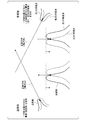
- FIG. 1 It is a figure which shows an example of the schematic structure of the communication system 1 which concerns on 1st Embodiment. It is a side view of the antenna device 4 which concerns on 1st Embodiment. It is a block diagram of the antenna device 100 of the angle diversity which arranged the two primary radiators 102, 103 in the vicinity of the focal point f3 of a parabolic reflector 101. It is a figure explaining the gain of the antenna device 100 shown in FIG. It is a figure which shows the simulation result of the gain and the peak angle in the front direction of the antenna device 100 and the antenna device 4 which concerns on 1st Embodiment. It is a side view of the antenna device 4B which concerns on 2nd Embodiment. It is a figure explaining the minimum structure of the antenna device which concerns on this embodiment.
- FIG. 1 is a diagram showing an example of a schematic configuration of the communication system 1 according to the first embodiment.
- the communication system 1 according to the present embodiment is a system that communicates by non-line-of-sight communication.
- Non-line-of-sight communication is a one-to-one communication method that uses tropospheric scattering and mountain diffraction of radio waves. For example, it is used for communication between distant points such as a transmission / reception point exceeding 100 km, or between points with obstacles in the middle such as a mountainous area.
- non-line-of-sight communication is used for the purpose of constructing a temporary communication line in the event of a disaster or emergency.
- Non-line-of-sight communication there are several radio wave transmission lines due to scattering and diffraction, so it is easily affected by fading. Therefore, in non-line-of-sight communication, a diversity method is often adopted in order to reduce the influence of fading.
- Diversity methods include a spatial diversity method in which a plurality of antennas are provided, a frequency diversity method using different frequencies, and an angle diversity method in which a plurality of primary radiators are constructed in one parabolic antenna.
- radio waves are transmitted and received by the angle diversity method.
- the communication system 1 includes a transmitting device 2 and a receiving device 3.
- the transmitting device 2 and the receiving device 3 each include an antenna device 4, and perform non-line-of-sight communication in an angle diversity system.
- the antenna devices 4 of the transmitting device 2 and the receiving device 3 each have the same configuration, but for the purpose of distinguishing them from each other, the antenna device 4 of the transmitting device 2 is referred to as a transmitting antenna, and the receiving device 3
- the antenna device 4 may be referred to as a receiving antenna.
- the transmitting device 2 radiates radio waves from the transmitting antenna.
- the radio waves radiated from the transmitting device 2 are scattered in the troposphere, for example, and propagate in a plurality of different directions.
- the receiving device 3 receives radio waves arriving from different directions with the receiving antenna.
- FIG. 2 is a configuration diagram of the antenna device 4 according to the first embodiment, and is a side view.
- the antenna device 4 is a so-called parabolic antenna.
- the antenna device 4 includes one reflector 10 and two primary radiators 11 and 12.
- the primary radiator 11 is an example of the "first primary radiator” of the present invention.
- the primary radiator 12 is an example of the "second primary radiator” of the present invention.
- the reflector 10 is a reflector having a parabolic curved surface.
- the reflector 10 has two focal points, a first focal point f1 and a second focal point f2.
- the first focal point f1 and the second focal point f2 are located on a straight line perpendicular to the central axis C of the reflector 10.
- the primary radiator 11 is provided at the position of the first focal point f1.
- the primary radiator 11 is a square waveguide.
- the primary radiator 12 is provided at the position of the second focal point f2.
- the primary radiator 12 is a square waveguide.
- the primary radiator 11 and the primary radiator 12 are adjacent to each other in a direction perpendicular to the central axis C of the reflector 10 (hereinafter, simply referred to as “vertical direction”).
- the primary radiator 11 and the primary radiator 12 may be integrally configured.
- the central axis C of the reflector 10 is defined as the "Z axis" in the Cartesian coordinate system of the three-dimensional space, the vertical direction is defined as the "Y axis”, and the direction perpendicular to the YZ plane is defined as the "X axis”.
- the reflector 10 includes a first parabolic mirror 20, a second parabolic mirror 21, and a flat member 22.
- the first parabolic mirror 20 is a reflector having a focal point of the first focal point f1.
- the second parabolic mirror 21 is a reflector having a focal point of the second focal point f2.
- the flat member 22 is a flat metal plate provided between the first parabolic mirror 20 and the second parabolic mirror 21. The flat member 22 connects to the first parabolic mirror 20 and the second parabolic mirror 21.
- the positions and shapes of the first parabolic mirror 20, the second parabolic mirror 21, and the flat member 22 will be specifically described.
- the center point K of the assumed parabolic mirror (hereinafter referred to as "virtual parabolic mirror") is set to (x1, y1, z2).
- z2 ⁇ z1. That is, the point M is located in the + Z axis direction with respect to the center point K.
- this virtual parabolic mirror is a reflector that reflects radio waves in the + Z axis direction.
- the virtual parabolic mirror is divided into two by a plane parallel to the X-axis direction and passing through the center point K.
- the upper virtual parabolic mirror of the virtual parabolic mirror divided into the two is referred to as the first parabolic mirror 20, and the lower virtual parabolic mirror is referred to as the second parabolic mirror 21. ..
- the first parabolic mirror 20 is arranged so that the position of the first focal point f1 coincides with the position of the primary radiator 11.
- the second parabolic mirror 21 is arranged so that the position of the second focal point f2 coincides with the position of the primary radiator 12.
- the position of the primary radiator 11 is (x1, y2, z1) and the position of the primary radiator 12 is (x1, y3, z1) is illustrated.
- the primary radiator 11 is located in the + Y axis direction with respect to the primary radiator 12.
- the upper virtual parabolic mirror divided into two is moved by the + Y axis direction (
- the first parabolic mirror 20 whose position of the first focal point f1 coincides with the position of the primary radiator 11 and the position of the second focal point f2 coincides with the position of the primary radiator 12.
- the parabolic mirror 21 of 2 is constructed.
- the flat member 22 is inserted in the gap between the first parabolic mirror 20 and the second parabolic mirror 21 divided into two, and the first parabolic mirror 20 and the second parabolic mirror 20 are inserted. It is connected to the parabolic mirror 21. Therefore, the length of the flat member 22 in the lateral direction corresponds to the interfocal distance between the first focal point f1 and the second focal point f2 in the Y-axis direction, and is (
- the flat member is an example of the "metal member" of the present invention.
- the primary radiator 11 radiates radio waves toward the reflector 10 in a direction parallel to the central axis C, that is, in the ⁇ Z axis direction.
- the radio wave radiated from the primary radiator 11 in the ⁇ Z axis direction is reflected by the first parabolic mirror 20 in the reflector 10 and radiated in the + Z axis direction (front direction).
- the primary radiator 12 does not radiate radio waves when the antenna device 4 is used as a transmitting antenna. That is, when the antenna device 4 is used as a transmitting antenna, only the primary radiator 11 of the primary radiator 11 and the primary radiator 12 radiates radio waves toward the reflector 10.
- the primary radiator 11 When the antenna device 4 is used as a receiving antenna, the primary radiator 11 receives the first radio wave reflected by the reflecting mirror 10.
- the primary radiator 12 receives the second radio wave reflected by the reflector 10 when the antenna device 4 is used as a receiving antenna. That is, when the antenna device 4 is used as a receiving antenna, both the primary radiator 11 and the primary radiator 12 are used.
- FIG. 3 is a configuration diagram of an angle diversity antenna device 100 in which two primary radiators 102 and 103 are arranged in the vicinity of the focal point f3 of the parabolic reflector 101.
- two primary radiators 102 and 103 are constructed in the vertical direction, that is, in the Y-axis direction, and are placed at the focal point f3 of the parabola reflector 101.
- the primary radiators 102 and 103 are square waveguides and have a volume.
- both the primary radiators 102 and 103 cannot be placed at the focal point f3, and the primary radiators 102 and 103 are arranged at positions deviated from the focal point f3, respectively. Therefore, the radiation direction of the radio wave radiated from the antenna device 100 deviates from the Z-axis direction by ⁇ . As a result, in the radiation pattern, as shown in FIG. 4, the peak of the radio wave in the Z-axis direction shifts. That is, in the angular diversity in which communication is performed in the Z-axis direction, the gain deteriorates in both transmission and reception.
- the antenna device 4 according to the first embodiment includes a reflector 10 having two focal points f1 and f2, the position of the focal point f1 is the position of the primary radiator 11, and the position of the focal point f2 is the primary.
- the reflector 10 is mirror-corrected to match the position of the radiator 12.
- FIG. 5 shows simulation results of gain and peak angle in the front direction in the antenna device 100 of the comparative example shown in FIG. 3 and the antenna device 4 according to the first embodiment. Note that FIG.
- the antenna device 4 according to the first embodiment has a smaller value of ⁇ and improved gain in the front direction as compared with the antenna device 100 in the comparative example. It was confirmed that
- the antenna device 4B according to the second embodiment is different from the antenna device 4 of the first embodiment in that the shape of the reflector is different, and the other configurations are the same as those of the first embodiment. is there.
- the same or similar parts may be designated by the same reference numerals to omit duplicate explanations.
- the antenna device 4B according to the second embodiment will be described below. Similar to the first embodiment, the antenna device 4B is used in both the transmitting device and the receiving device in non-line-of-sight communication in which radio waves are transmitted and received in an angle diversity manner.
- the antenna device 4B is a so-called parabolic antenna.
- FIG. 6 is a diagram showing an example of a schematic configuration of the antenna device 4B according to the second embodiment.
- the antenna device 4B includes one reflector 10B and two primary radiators 11 and 12.
- the reflector 10B is a reflector having a parabolic curved surface.
- the reflector 10B has two focal points, a first focal point f1 and a second focal point f2.
- the first focal point f1 and the second focal point f2 are located on a straight line in a direction perpendicular to the central axis C of the reflecting mirror 10B.
- the reflector 10B is a reflector whose mirror surface is a parabolic surface passing through each intermediate point between the first virtual parabolic mirror 30 and the second virtual parabolic mirror 40 when viewed from the X-axis direction.
- the first virtual parabolic mirror 30 is a virtual parabolic mirror whose focal point (first focus f1) coincides with the position of the primary radiator 11.
- the second virtual parabolic mirror 40 is a virtual parabolic mirror whose focal point (second focus f2) coincides with the position of the primary radiator 12.
- the first virtual parabolic mirror 30 has a parabolic surface rotated around the first focal point f1 with the surface center K1 as a base point.
- the second virtual parabolic mirror 40 has a parabolic surface rotated around the second focal point f2 with the surface center K2 as a base point.
- the reflector 10B is a curved surface that plots the midpoint between the parabolic surface of the first virtual parabolic mirror 30 and the parabolic surface of the second virtual parabolic mirror 40 when viewed from the X-axis direction. Is a reflector whose mirror surface is modified (hereinafter referred to as "mirror surface correction") so that it becomes a mirror surface.
- the antenna device 4B according to the second embodiment includes a reflector 10B having two focal points f1 and f2. Further, the reflector 10B is mirror-corrected so that the position of the focal point f1 coincides with the position of the primary radiator 11 and the position of the focal point f2 coincides with the position of the primary radiator 12. As a result, the deviation of ⁇ is improved, and the deterioration of the gain in the Z-axis direction can be improved in both transmission and reception. Since the operation of the antenna device 4B according to the second embodiment is the same as that of the first embodiment, the description thereof will be omitted.
- the antenna device includes a reflector 10C and two primary radiators 11 and 12.
- the reflector 10C has two focal points f1 and f2.
- the primary radiators 11 and 12 are provided at the respective positions of the focal points f1 and f2 of the reflector 10C.
- the reflector 10C may be the reflector 10 according to the first embodiment or the reflector 10B according to the second embodiment.
- the reflecting mirror 10C is not limited to the reflecting mirror 10 and the reflecting mirror 10B, and may have any shape as long as it is a parabolic reflecting mirror having two focal points f1 and f2. Further, the focal point of the reflector 10C is not limited to the two focal points f1 and f2, and may have more than two focal points.
- the method of designing the antenna device according to the first embodiment or the second embodiment includes, for example, at least the first step and the second step.
- the first step is a step of installing the primary radiator 11 and the primary radiator 12 capable of radiating electromagnetic waves to the reflector 10 (or the reflector 10B) adjacent to each other at predetermined positions.
- the second step is a step of designing the mirror surface of the reflector 10 (or the reflector 10B). That is, the second step has a first focus f1 and a second focus f2, the first focus f1 coincides with the installation position of the primary radiator 11, and the first focus f1 coincides with the installation position of the primary radiator 12.
- the mirror surface of the reflector 10 (or the reflector 10B) is designed so that the focal points f2 of 2 are aligned.
- the present invention it is possible to improve the deterioration of the gain of the antenna device in a desired direction.
Landscapes
- Physics & Mathematics (AREA)
- Electromagnetism (AREA)
- Aerials With Secondary Devices (AREA)
Abstract
Description
図1は、第1の実施形態に係る通信システム1の概略構成の一例を示す図である。
本実施形態に係る通信システム1は、見通し外通信により通信を行うシステムである。
図1に示すように、通信システム1は、送信装置2及び受信装置3を備える。
送信装置2及び受信装置3は、それぞれアンテナ装置4を備え、角度ダイバーシティ方式で見通し外通信を行う。
なお、送信装置2及び受信装置3の各アンテナ装置4は、それぞれ同様の構成を備えているが、互いを区別する目的として、送信装置2のアンテナ装置4を送信アンテナと称し、受信装置3のアンテナ装置4を受信アンテナと称する場合がある。
受信装置3は、それぞれ異なった方向から到達する電波を、受信アンテナで受信する。
アンテナ装置4は、いわゆるパラボラアンテナである。
図2に示すように、アンテナ装置4は、一つの反射鏡10及び二つの一次放射器11,12を備える。一次放射器11は、本発明の「第1の一次放射器」の一例である。一次放射器12は、本発明の「第2の一次放射器」の一例である。
第1の焦点f1及び第2の焦点f2は、反射鏡10の中心軸Cに垂直な一直線上に位置している。
一次放射器12は、第2の焦点f2の位置に設けられている。一次放射器12は、正方形の導波管である。
一次放射器11及び一次放射器12は、反射鏡10の中心軸Cに垂直な方向(以下、単に「垂直方向」という。)において互いに隣接している。例えば、一次放射器11及び一次放射器12は、一体で構成されてもよい。ここで、反射鏡10の中心軸Cを三次元空間の直交座標系における「Z軸」とし、上記垂直方向を「Y軸」とし、YZ平面に垂直な方向を「X軸」とする。
反射鏡10は、第1の放物面鏡20、第2の放物面鏡21及び平面部材22を備える。
第1の放物面鏡20は、焦点を第1の焦点f1とする反射鏡である。
第2の放物面鏡21は、焦点を第2の焦点f2とする反射鏡である。
平面部材22は、第1の放物面鏡20と第2の放物面鏡21との間に設けられた平面の金属板である。平面部材22は、第1の放物面鏡20と第2の放物面鏡21と接続する。
上記直交座標系において、Z軸の任意の点である点M(x1、y1、z1)を焦点とする一つの放物面鏡を仮定する。また、仮定した当該放物面鏡(以下、「仮想放物面鏡」という。)の中心点Kを(x1、y1、z2)とする。なお、z2<z1である。つまり、点Mは、中心点Kに対して+Z軸方向に位置する。
例えば、この仮想放物面鏡は、+Z軸方向に電波を反射する反射鏡である。そして、この仮想放物面鏡が、X軸方向に平行であってかつ中心点Kを通る平面によって、2つに分割される。その2つに分割された仮想放物面鏡の上側の仮想放物面鏡を第1の放物面鏡20とし、下側の仮想放物面鏡を第2の放物面鏡21とする。さらに、第1の放物面鏡20は、その第1の焦点f1の位置が一次放射器11の位置に一致するように配置される。また、第2の放物面鏡21は、その第2の焦点f2の位置が一次放射器12の位置に一致するように配置される。
本実施形態では、一次放射器11の位置を(x1、y2、z1)、一次放射器12の位置を(x1、y3、z1)とした場合を例示する。この例において、一次放射器11は、一次放射器12に対して+Y軸方向に位置する。2つに分割した仮想放物面鏡の上側の仮想放物面鏡が+Y軸方向に(|y1-y2|)だけ移動され、下側の仮想放物面鏡が-Y軸方向に(|y1-y3|)だけ移動される。これにより、その第1の焦点f1の位置が一次放射器11の位置と一致する第1の放物面鏡20と、その第2の焦点f2の位置が一次放射器12の位置と一致する第2の放物面鏡21と、が構築される。
なお、平面部材は、本発明の「金属部材」の一例である。
一次放射器11は、アンテナ装置4が送信アンテナとして使用される場合には、電波を中心軸Cに平行な方向、すなわち-Z軸方向に、反射鏡10に向けて放射する。一次放射器11から-Z軸方向に放射された電波は、反射鏡10における第1の放物面鏡20で反射して+Z軸方向(正面方向)に放射される。一方、一次放射器12は、アンテナ装置4が送信アンテナとして使用される場合には、電波を放射しない。すなわち、アンテナ装置4が送信アンテナとして使用される場合には、一次放射器11及び一次放射器12のうち、一次放射器11のみが電波を反射鏡10に向けて放射する。
図3に示すように、アンテナ装置100は、垂直方向、すなわちY軸方向に2つの一次放射器102,103が構築されており、パラボラ反射鏡101の焦点f3に置かれている。ここで、一次放射器102,103は、正方形の導波管であり体積がある。そのため、一次放射器102,103の双方を焦点f3に置くことができず、一次放射器102,103は、焦点f3からずれた位置にそれぞれ配置される。したがって、アンテナ装置100から放射される電波の放射方向は、Z軸方向からΔθだけずれてしまう。その結果、放射パターンは、図4に示すように、Z軸方向における電波のピークがずれてしまう。すなわち、Z軸方向での通信を行う角度ダイバーシティにおいて、送信及び受信ともに利得が劣化する。
図5において、図3に示した比較例のアンテナ装置100と、第1の実施形態に係るアンテナ装置4とにおける、正面方向の利得とピーク角度のシミュレーション結果を示す。なお、図5は、アンテナ装置の口径を10mとし、焦点距離を4.3mとしてシミュレーションを行った場合のシミュレーション結果を示す。
図5に示すように、シミュレーション結果から、第1の実施形態に係るアンテナ装置4は、比較例におけるアンテナ装置100と比較して、Δθの値が小さくなり、且つ、正面方向の利得も改善されることが確認された。
以下において、第2の実施形態に係るアンテナ装置4Bについて説明する。第2の実施形態に係るアンテナ装置4Bは、第1の実施形態のアンテナ装置4と比較して、反射鏡の形状が異なる点で相違し、その他の構成については第1の実施形態と同様である。なお、図面において、同一又は類似の部分には同一の符号を付して、重複する説明を省く場合がある。
アンテナ装置4Bは、第1の実施形態と同様に、角度ダイバーシティ方式で電波の送受信を行う見通し外通信において、送信装置及び受信装置の双方において用いられる。
アンテナ装置4Bは、いわゆるパラボラアンテナである。
図6に示すように、アンテナ装置4Bは、一つの反射鏡10B、及び二つの一次放射器11,12を備える。
第1の焦点f1及び第2の焦点f2は、反射鏡10Bの中心軸Cに対して垂直な方向における一直線上に位置している。
反射鏡10Bは、X軸方向から見て、第1の仮想放物面鏡30と第2の仮想放物面鏡40との間の各中間点を通る放物面を、鏡面とする反射鏡である。第1の仮想放物面鏡30は、一次放射器11の位置にその焦点(第1の焦点f1)が一致する仮想的な放物面鏡である。第2の仮想放物面鏡40は、一次放射器12の位置にその焦点(第2の焦点f2)が一致する仮想的な放物面鏡である。
第1の仮想放物面鏡30は、その面中心K1を基点として、第1の焦点f1を中心に回転させた放物面を有する。
第2の仮想放物面鏡40は、その面中心K2を基点として、第2の焦点f2を中心に回転させた放物面を有する。
反射鏡10Bは、X軸方向から見た場合における、第1の仮想放物面鏡30の放物面と、第2の仮想放物面鏡40の放物面との中間点をプロットした曲面を鏡面となるように鏡面を修正(以下、「鏡面修正」という。)した反射鏡である。
なお、第2の実施形態に係るアンテナ装置4Bの動作は、第1の実施形態と同様であるため、説明を省略する。
アンテナ装置の最小構成の実施形態について、図7を参照して説明する。
本実施形態に係るアンテナ装置は、反射鏡10C及び2つの一次放射器11,12を備える。
反射鏡10Cは、二つの焦点f1,f2を有する。
一次放射器11,12は、反射鏡10Cの焦点f1,f2の各位置に設けられている。
これにより、上記Δθのずれが改善され、送信受信ともにZ軸方向の利得の劣化を改善することができる。
なお、反射鏡10Cは、第1の実施形態に係る反射鏡10であってもよいし、第2の実施形態に係る反射鏡10Bであってもよい。また、反射鏡10Cは、反射鏡10や反射鏡10Bに限定されず、二つの焦点f1,f2を備えるパラボラ反射鏡であれば、どのような形状であってもよい。
さらに、反射鏡10Cの焦点は、二つの焦点f1及びf2に限定されず、二より多い焦点を有してもよい。
第1ステップは、反射鏡10(又は反射鏡10B)に対して電磁波を放射可能な一次放射器11及び一次放射器12を隣接して所定の位置に設置するステップである。
第2ステップは、反射鏡10(又は反射鏡10B)の鏡面を設計するステップである。すなわち、第2ステップは、第1の焦点f1及び第2の焦点f2を有し、一次放射器11の設置位置にその第1の焦点f1が一致し、一次放射器12の設置位置にその第2の焦点f2が一致するように、反射鏡10(又は反射鏡10B)の鏡面を設計する。
10,10B 反射鏡
11,12 一次放射器
20 第1の放物面鏡
21 第2の放物面鏡
22 平面部材
f1 第1の焦点
f2 第2の焦点
Claims (7)
- 複数の焦点を有する一つの反射鏡と、
前記複数の焦点の各位置に設けられた複数の一次放射器と、
を備えるアンテナ装置。 - 前記複数の焦点は、前記反射鏡の中心軸に垂直な一直線上に位置している、
請求項1に記載のアンテナ装置。 - 前記複数の一次放射器は、前記垂直な方向において互いに隣接している、
請求項2に記載のアンテナ装置。 - 前記反射鏡は、
第1の焦点を有する第1の放物面鏡と、
第2の焦点を有する第2の放物面鏡と、
前記第1の放物面鏡と前記第2の放物面鏡との間に設けられた金属部材と、
を備え、
前記第1の焦点及び前記第2の焦点の各位置は、前記垂直な方向において隣接している前記複数の一次放射器の位置と一致している、
請求項2又は請求項3に記載のアンテナ装置。 - 前記第1の焦点と前記第2の焦点との間の焦点間距離は、前記金属部材の短手方向の長さと一致する、請求項4に記載のアンテナ装置。
- 前記複数の一次放射器は、前記垂直な方向において隣接している第1の一次放射器及び第2の一次放射器であり、
前記反射鏡は、前記第1の一次放射器の位置とその焦点が一致する仮想的な第1の放物面鏡と、前記第2の一次放射器の位置とその焦点が一致する仮想的な第2の放物面鏡と、の間の各中間点を通る放物面を鏡面とする、
ことを特徴とする、
請求項2又は請求項3に記載のアンテナ装置。 - 反射鏡に対して電磁波を放射可能な第1の一次放射器及び第2の一次放射器を互いに隣接して所定の位置に設置する第1ステップと、
第1の焦点及び第2の焦点を有し、前記第1の一次放射器の設置位置に前記第1の焦点が一致し、前記第2の一次放射器の設置位置に前記第2の焦点が一致するように前記反射鏡の鏡面を設計する第2ステップと、
を含むアンテナ装置の設計方法。
Priority Applications (3)
| Application Number | Priority Date | Filing Date | Title |
|---|---|---|---|
| JP2021526899A JP7255678B2 (ja) | 2019-06-20 | 2020-06-19 | アンテナ装置及びその設計方法 |
| US17/618,259 US11769953B2 (en) | 2019-06-20 | 2020-06-19 | Antenna device and method for designing same |
| EP20827279.9A EP3989362A4 (en) | 2019-06-20 | 2020-06-19 | ANTENNA DEVICE AND DESIGN METHOD THEREOF |
Applications Claiming Priority (2)
| Application Number | Priority Date | Filing Date | Title |
|---|---|---|---|
| JP2019114922 | 2019-06-20 | ||
| JP2019-114922 | 2019-06-20 |
Publications (1)
| Publication Number | Publication Date |
|---|---|
| WO2020256093A1 true WO2020256093A1 (ja) | 2020-12-24 |
Family
ID=74040493
Family Applications (1)
| Application Number | Title | Priority Date | Filing Date |
|---|---|---|---|
| PCT/JP2020/024086 WO2020256093A1 (ja) | 2019-06-20 | 2020-06-19 | アンテナ装置及びその設計方法 |
Country Status (4)
| Country | Link |
|---|---|
| US (1) | US11769953B2 (ja) |
| EP (1) | EP3989362A4 (ja) |
| JP (1) | JP7255678B2 (ja) |
| WO (1) | WO2020256093A1 (ja) |
Cited By (1)
| Publication number | Priority date | Publication date | Assignee | Title |
|---|---|---|---|---|
| WO2024031929A1 (zh) * | 2022-08-10 | 2024-02-15 | 胡关平 | 一种双焦组合抛物面天线 |
Citations (4)
| Publication number | Priority date | Publication date | Assignee | Title |
|---|---|---|---|---|
| JPS5062345A (ja) * | 1973-10-01 | 1975-05-28 | ||
| JPS5315045A (en) * | 1976-07-27 | 1978-02-10 | Mitsubishi Electric Corp | Multi-frequency common-use antenna |
| JPS63146502A (ja) * | 1986-12-09 | 1988-06-18 | Nec Corp | マルチビ−ムアンテナ |
| JP2019114922A (ja) | 2017-12-22 | 2019-07-11 | キヤノン株式会社 | 電子機器、その制御方法およびプログラム |
Family Cites Families (26)
| Publication number | Priority date | Publication date | Assignee | Title |
|---|---|---|---|---|
| NL278997A (ja) * | 1961-07-31 | |||
| US3795004A (en) * | 1973-02-26 | 1974-02-26 | Us Army | Cassegrain radar antenna with selectable acquisition and track modes |
| JPS56110305A (en) | 1980-02-05 | 1981-09-01 | Nec Corp | Fan-shaped beam antenna |
| JPH04100302A (ja) | 1990-08-18 | 1992-04-02 | Nec Corp | マルチビームアンテナ |
| US5298909A (en) * | 1991-12-11 | 1994-03-29 | The Boeing Company | Coaxial multiple-mode antenna system |
| JP2545737B2 (ja) * | 1994-01-10 | 1996-10-23 | 郵政省通信総合研究所長 | ガウシアンビーム型アンテナ装置 |
| US5440801A (en) * | 1994-03-03 | 1995-08-15 | Composite Optics, Inc. | Composite antenna |
| US6061033A (en) * | 1997-11-06 | 2000-05-09 | Raytheon Company | Magnified beam waveguide antenna system for low gain feeds |
| JP3489985B2 (ja) | 1998-02-06 | 2004-01-26 | 三菱電機株式会社 | アンテナ装置 |
| US6172650B1 (en) * | 1998-07-02 | 2001-01-09 | Kabushiki Kaisha Toyota Chuo Kenkyusho | Antenna system |
| GB9914162D0 (en) * | 1999-06-18 | 1999-08-18 | Secr Defence Brit | Steerable transponders |
| JP2001185946A (ja) * | 1999-10-14 | 2001-07-06 | Toyota Central Res & Dev Lab Inc | アンテナ装置 |
| GB0220434D0 (en) * | 2002-09-03 | 2004-03-17 | Qinetiq Ltd | Detection device |
| US7878191B2 (en) * | 2007-10-31 | 2011-02-01 | Bender William H | Solar collector stabilized by cables and a compression element |
| EP2234204A4 (en) * | 2007-12-07 | 2010-12-22 | Nec Corp | PARABOLIC ANTENNA |
| US8368608B2 (en) * | 2008-04-28 | 2013-02-05 | Harris Corporation | Circularly polarized loop reflector antenna and associated methods |
| US9063402B2 (en) * | 2010-03-26 | 2015-06-23 | Nec Corporation | Illuminating optical system and projector using the same |
| US8686910B1 (en) * | 2010-04-12 | 2014-04-01 | Calabazas Creek Research, Inc. | Low reflectance radio frequency load |
| US8322332B2 (en) * | 2010-11-08 | 2012-12-04 | Rogers William E | Self-erecting gimbal mounted solar radiation collectors |
| EP2835868B1 (en) * | 2012-04-02 | 2016-09-14 | Furuno Electric Co., Ltd. | Antenna |
| WO2017056136A1 (ja) * | 2015-10-01 | 2017-04-06 | 日本電気株式会社 | 無線信号送信アンテナ、無線信号受信アンテナ、無線信号送受信システム、無線信号送信方法および無線信号受信方法 |
| WO2018056194A1 (ja) * | 2016-09-21 | 2018-03-29 | 日本電気株式会社 | 投射システム |
| US10361489B2 (en) * | 2016-12-01 | 2019-07-23 | At&T Intellectual Property I, L.P. | Dielectric dish antenna system and methods for use therewith |
| WO2018109837A1 (ja) * | 2016-12-13 | 2018-06-21 | 三菱電機株式会社 | 反射鏡アンテナ装置 |
| JP2019220792A (ja) * | 2018-06-18 | 2019-12-26 | パナソニックIpマネジメント株式会社 | アンテナ装置および無線装置 |
| US11428844B2 (en) * | 2019-03-23 | 2022-08-30 | Steel City Optronics, LLC | Advanced multi-camera imaging system with polarization responsive antennas |
-
2020
- 2020-06-19 EP EP20827279.9A patent/EP3989362A4/en active Pending
- 2020-06-19 WO PCT/JP2020/024086 patent/WO2020256093A1/ja active Application Filing
- 2020-06-19 JP JP2021526899A patent/JP7255678B2/ja active Active
- 2020-06-19 US US17/618,259 patent/US11769953B2/en active Active
Patent Citations (4)
| Publication number | Priority date | Publication date | Assignee | Title |
|---|---|---|---|---|
| JPS5062345A (ja) * | 1973-10-01 | 1975-05-28 | ||
| JPS5315045A (en) * | 1976-07-27 | 1978-02-10 | Mitsubishi Electric Corp | Multi-frequency common-use antenna |
| JPS63146502A (ja) * | 1986-12-09 | 1988-06-18 | Nec Corp | マルチビ−ムアンテナ |
| JP2019114922A (ja) | 2017-12-22 | 2019-07-11 | キヤノン株式会社 | 電子機器、その制御方法およびプログラム |
Cited By (1)
| Publication number | Priority date | Publication date | Assignee | Title |
|---|---|---|---|---|
| WO2024031929A1 (zh) * | 2022-08-10 | 2024-02-15 | 胡关平 | 一种双焦组合抛物面天线 |
Also Published As
| Publication number | Publication date |
|---|---|
| US11769953B2 (en) | 2023-09-26 |
| JP7255678B2 (ja) | 2023-04-11 |
| JPWO2020256093A1 (ja) | 2020-12-24 |
| EP3989362A4 (en) | 2022-08-10 |
| US20220352642A1 (en) | 2022-11-03 |
| EP3989362A1 (en) | 2022-04-27 |
Similar Documents
| Publication | Publication Date | Title |
|---|---|---|
| US10727607B2 (en) | Horn antenna | |
| US8665166B2 (en) | Compact multibeam reflector antenna | |
| WO2020256093A1 (ja) | アンテナ装置及びその設計方法 | |
| JP2018507664A (ja) | 集束アンテナを備えた集積型トランシーバ | |
| JP2018137743A (ja) | リフレクトアレーアンテナ | |
| WO2018120197A1 (zh) | 一种天线及通信设备 | |
| TW202224268A (zh) | 反射單元及無線傳送系統 | |
| CN116636090A (zh) | 具有高增益天线布置的无线收发器 | |
| EP3547451B1 (en) | Reflection mirror antenna device | |
| JPH05267928A (ja) | 反射鏡アンテナ | |
| JP4584727B2 (ja) | マルチビームフィードホーン、周波数変換器及びマルチビームアンテナ | |
| WO2020158045A1 (ja) | アンテナ装置 | |
| JP6245561B2 (ja) | アンテナ装置 | |
| WO2023210414A1 (ja) | 通信システム、電波屈折板および電波屈折板の設置位置の算出方法 | |
| WO2023171076A1 (ja) | アンテナ装置 | |
| US10601143B2 (en) | Antenna apparatus | |
| JP2007060324A (ja) | アンテナ装置 | |
| JP3034262B2 (ja) | 開口面アンテナ装置 | |
| JP6501981B2 (ja) | アンテナ装置 | |
| JPS639207A (ja) | 加入者無線方式 | |
| CN112151949A (zh) | 一种龙伯透镜天线 | |
| JPH0295003A (ja) | 走査アンテナ | |
| JPH02239704A (ja) | アンテナ装置 | |
| JPS61240721A (ja) | 多方向見通し外無線通信方式 | |
| JPH01314004A (ja) | 多周波数帯共用アンテナ給電装置 |
Legal Events
| Date | Code | Title | Description |
|---|---|---|---|
| 121 | Ep: the epo has been informed by wipo that ep was designated in this application |
Ref document number: 20827279 Country of ref document: EP Kind code of ref document: A1 |
|
| ENP | Entry into the national phase |
Ref document number: 2021526899 Country of ref document: JP Kind code of ref document: A |
|
| NENP | Non-entry into the national phase |
Ref country code: DE |
|
| WWE | Wipo information: entry into national phase |
Ref document number: 2020827279 Country of ref document: EP |
|
| ENP | Entry into the national phase |
Ref document number: 2020827279 Country of ref document: EP Effective date: 20220120 |