WO2022085778A1 - 車両用内装品 - Google Patents
車両用内装品 Download PDFInfo
- Publication number
- WO2022085778A1 WO2022085778A1 PCT/JP2021/039024 JP2021039024W WO2022085778A1 WO 2022085778 A1 WO2022085778 A1 WO 2022085778A1 JP 2021039024 W JP2021039024 W JP 2021039024W WO 2022085778 A1 WO2022085778 A1 WO 2022085778A1
- Authority
- WO
- WIPO (PCT)
- Prior art keywords
- vehicle
- light emitting
- seat
- power generation
- vehicle interior
- Prior art date
- Legal status (The legal status is an assumption and is not a legal conclusion. Google has not performed a legal analysis and makes no representation as to the accuracy of the status listed.)
- Ceased
Links
Images






















Classifications
-
- B—PERFORMING OPERATIONS; TRANSPORTING
- B60—VEHICLES IN GENERAL
- B60J—WINDOWS, WINDSCREENS, NON-FIXED ROOFS, DOORS, OR SIMILAR DEVICES FOR VEHICLES; REMOVABLE EXTERNAL PROTECTIVE COVERINGS SPECIALLY ADAPTED FOR VEHICLES
- B60J5/00—Doors
- B60J5/04—Doors arranged at the vehicle sides
- B60J5/042—Reinforcement elements
- B60J5/0451—Block or short strip-type elements
-
- B—PERFORMING OPERATIONS; TRANSPORTING
- B60—VEHICLES IN GENERAL
- B60J—WINDOWS, WINDSCREENS, NON-FIXED ROOFS, DOORS, OR SIMILAR DEVICES FOR VEHICLES; REMOVABLE EXTERNAL PROTECTIVE COVERINGS SPECIALLY ADAPTED FOR VEHICLES
- B60J5/00—Doors
- B60J5/04—Doors arranged at the vehicle sides
- B60J5/042—Reinforcement elements
- B60J5/0422—Elongated type elements, e.g. beams, cables, belts or wires
- B60J5/0423—Elongated type elements, e.g. beams, cables, belts or wires characterised by position in the lower door structure
- B60J5/0425—Elongated type elements, e.g. beams, cables, belts or wires characterised by position in the lower door structure the elements being arranged essentially horizontal in the centre of the lower door structure
-
- B—PERFORMING OPERATIONS; TRANSPORTING
- B60—VEHICLES IN GENERAL
- B60J—WINDOWS, WINDSCREENS, NON-FIXED ROOFS, DOORS, OR SIMILAR DEVICES FOR VEHICLES; REMOVABLE EXTERNAL PROTECTIVE COVERINGS SPECIALLY ADAPTED FOR VEHICLES
- B60J5/00—Doors
- B60J5/04—Doors arranged at the vehicle sides
- B60J5/0468—Fixation or mounting means specific for door components
- B60J5/0469—Fixation or mounting means specific for door components for door panels, e.g. hemming
-
- B—PERFORMING OPERATIONS; TRANSPORTING
- B60—VEHICLES IN GENERAL
- B60Q—ARRANGEMENT OF SIGNALLING OR LIGHTING DEVICES, THE MOUNTING OR SUPPORTING THEREOF OR CIRCUITS THEREFOR, FOR VEHICLES IN GENERAL
- B60Q3/00—Arrangement of lighting devices for vehicle interiors; Lighting devices specially adapted for vehicle interiors
- B60Q3/20—Arrangement of lighting devices for vehicle interiors; Lighting devices specially adapted for vehicle interiors for lighting specific fittings of passenger or driving compartments; mounted on specific fittings of passenger or driving compartments
- B60Q3/217—Doors, e.g. door sills; Steps
-
- B—PERFORMING OPERATIONS; TRANSPORTING
- B60—VEHICLES IN GENERAL
- B60Q—ARRANGEMENT OF SIGNALLING OR LIGHTING DEVICES, THE MOUNTING OR SUPPORTING THEREOF OR CIRCUITS THEREFOR, FOR VEHICLES IN GENERAL
- B60Q3/00—Arrangement of lighting devices for vehicle interiors; Lighting devices specially adapted for vehicle interiors
- B60Q3/50—Mounting arrangements
- B60Q3/54—Lighting devices embedded in interior trim, e.g. in roof liners
-
- B—PERFORMING OPERATIONS; TRANSPORTING
- B60—VEHICLES IN GENERAL
- B60Q—ARRANGEMENT OF SIGNALLING OR LIGHTING DEVICES, THE MOUNTING OR SUPPORTING THEREOF OR CIRCUITS THEREFOR, FOR VEHICLES IN GENERAL
- B60Q3/00—Arrangement of lighting devices for vehicle interiors; Lighting devices specially adapted for vehicle interiors
- B60Q3/70—Arrangement of lighting devices for vehicle interiors; Lighting devices specially adapted for vehicle interiors characterised by the purpose
- B60Q3/78—Arrangement of lighting devices for vehicle interiors; Lighting devices specially adapted for vehicle interiors characterised by the purpose for generating luminous strips, e.g. for marking trim component edges
-
- B—PERFORMING OPERATIONS; TRANSPORTING
- B60—VEHICLES IN GENERAL
- B60Q—ARRANGEMENT OF SIGNALLING OR LIGHTING DEVICES, THE MOUNTING OR SUPPORTING THEREOF OR CIRCUITS THEREFOR, FOR VEHICLES IN GENERAL
- B60Q3/00—Arrangement of lighting devices for vehicle interiors; Lighting devices specially adapted for vehicle interiors
- B60Q3/80—Circuits; Control arrangements
-
- B—PERFORMING OPERATIONS; TRANSPORTING
- B60—VEHICLES IN GENERAL
- B60R—VEHICLES, VEHICLE FITTINGS, OR VEHICLE PARTS, NOT OTHERWISE PROVIDED FOR
- B60R13/00—Elements for body-finishing, identifying, or decorating; Arrangements or adaptations for advertising purposes
- B60R13/02—Internal Trim mouldings ; Internal Ledges; Wall liners for passenger compartments; Roof liners
-
- F—MECHANICAL ENGINEERING; LIGHTING; HEATING; WEAPONS; BLASTING
- F21—LIGHTING
- F21S—NON-PORTABLE LIGHTING DEVICES; SYSTEMS THEREOF; VEHICLE LIGHTING DEVICES SPECIALLY ADAPTED FOR VEHICLE EXTERIORS
- F21S9/00—Lighting devices with a built-in power supply; Systems employing lighting devices with a built-in power supply
- F21S9/02—Lighting devices with a built-in power supply; Systems employing lighting devices with a built-in power supply the power supply being a battery or accumulator
- F21S9/03—Lighting devices with a built-in power supply; Systems employing lighting devices with a built-in power supply the power supply being a battery or accumulator rechargeable by exposure to light
-
- B—PERFORMING OPERATIONS; TRANSPORTING
- B60—VEHICLES IN GENERAL
- B60J—WINDOWS, WINDSCREENS, NON-FIXED ROOFS, DOORS, OR SIMILAR DEVICES FOR VEHICLES; REMOVABLE EXTERNAL PROTECTIVE COVERINGS SPECIALLY ADAPTED FOR VEHICLES
- B60J5/00—Doors
- B60J5/04—Doors arranged at the vehicle sides
- B60J5/042—Reinforcement elements
- B60J5/0422—Elongated type elements, e.g. beams, cables, belts or wires
- B60J5/0438—Elongated type elements, e.g. beams, cables, belts or wires characterised by the type of elongated elements
- B60J5/0443—Beams
- B60J5/0444—Beams characterised by a special cross section
-
- F—MECHANICAL ENGINEERING; LIGHTING; HEATING; WEAPONS; BLASTING
- F21—LIGHTING
- F21W—INDEXING SCHEME ASSOCIATED WITH SUBCLASSES F21K, F21L, F21S and F21V, RELATING TO USES OR APPLICATIONS OF LIGHTING DEVICES OR SYSTEMS
- F21W2106/00—Interior vehicle lighting devices
-
- F—MECHANICAL ENGINEERING; LIGHTING; HEATING; WEAPONS; BLASTING
- F21—LIGHTING
- F21W—INDEXING SCHEME ASSOCIATED WITH SUBCLASSES F21K, F21L, F21S and F21V, RELATING TO USES OR APPLICATIONS OF LIGHTING DEVICES OR SYSTEMS
- F21W2107/00—Use or application of lighting devices on or in particular types of vehicles
- F21W2107/10—Use or application of lighting devices on or in particular types of vehicles for land vehicles
- F21W2107/13—Use or application of lighting devices on or in particular types of vehicles for land vehicles for cycles
-
- F—MECHANICAL ENGINEERING; LIGHTING; HEATING; WEAPONS; BLASTING
- F21—LIGHTING
- F21W—INDEXING SCHEME ASSOCIATED WITH SUBCLASSES F21K, F21L, F21S and F21V, RELATING TO USES OR APPLICATIONS OF LIGHTING DEVICES OR SYSTEMS
- F21W2107/00—Use or application of lighting devices on or in particular types of vehicles
- F21W2107/20—Use or application of lighting devices on or in particular types of vehicles for water vehicles
-
- F—MECHANICAL ENGINEERING; LIGHTING; HEATING; WEAPONS; BLASTING
- F21—LIGHTING
- F21W—INDEXING SCHEME ASSOCIATED WITH SUBCLASSES F21K, F21L, F21S and F21V, RELATING TO USES OR APPLICATIONS OF LIGHTING DEVICES OR SYSTEMS
- F21W2107/00—Use or application of lighting devices on or in particular types of vehicles
- F21W2107/30—Use or application of lighting devices on or in particular types of vehicles for aircraft
-
- F—MECHANICAL ENGINEERING; LIGHTING; HEATING; WEAPONS; BLASTING
- F21—LIGHTING
- F21Y—INDEXING SCHEME ASSOCIATED WITH SUBCLASSES F21K, F21L, F21S and F21V, RELATING TO THE FORM OR THE KIND OF THE LIGHT SOURCES OR OF THE COLOUR OF THE LIGHT EMITTED
- F21Y2115/00—Light-generating elements of semiconductor light sources
- F21Y2115/10—Light-emitting diodes [LED]
- F21Y2115/15—Organic light-emitting diodes [OLED]
Definitions
- the present invention relates to an interior product for a vehicle, and more particularly to an interior product for a vehicle, which is attached to the interior side of the vehicle and includes a light emitting member that emits light toward the inside of the vehicle.
- Patent Document 1 proposes, as an example of decorative parts for vehicles, a door lining for vehicles that functions as decorative lighting and can be harmonized with peripheral members when the lights are turned off from the viewpoint of improving design. There is.
- the present invention has been made in view of the above problems, and an object of the present invention is for a vehicle capable of exerting a lighting function in a vehicle even if electricity is not supplied from a power source of the vehicle body. It is to provide interior goods. Another object of the present invention is to provide a vehicle interior product capable of compactly arranging components for exhibiting a lighting function and suppressing an increase in size. Another object of the present invention is to provide an interior product for a vehicle capable of efficiently generating power generation members in order to exert a lighting function.
- the problem is a vehicle interior product to be attached to a vehicle, in which a light emitting member that emits light toward the inside of the vehicle is electrically connected to the light emitting member.
- the vehicle includes a power generation member that supplies electricity to the light emitting member, the light emitting member, and a storage member that is electrically connected to the power generation member and stores electricity, and the power generation member is in the form of a sheet or a film. It is solved by being arranged along the surface of the interior parts. With the above configuration, it is possible to realize an interior product for a vehicle capable of exerting a lighting function in the vehicle without supplying electricity from a power source of the vehicle body.
- the interior parts for vehicles are provided with a light emitting member, a power generation member, and a power storage member, it is possible to generate electricity by itself to supply electricity and exert a lighting function.
- the power generation member is in the form of a sheet or a film, it is possible to compactly arrange the components for exhibiting the lighting function and suppress the increase in size.
- the sheet-shaped or film-shaped power generation member is arranged along the surface of the vehicle interior product, for example, even if the outer surface of the vehicle interior product has a curved surface portion, the outer surface of the vehicle interior product is made to follow the outer surface.
- a power generation member can be suitably attached.
- the vehicle interior is a vehicle door lining provided inside the vehicle door, and the light emitting member, the power generating member, and the power storage member are inside the vehicle door lining. It is preferable that they are arranged at different positions on the surface.
- the light emitting member, the power generation member, and the power storage member can be compactly arranged in the vehicle door lining, and the increase in size can be suppressed in the thickness direction of the vehicle door lining.
- the power generation member is a film-shaped solar cell module, which is attached to the upper portion of the vehicle interior product and is arranged at a position above the power generation member and the power storage member.
- the solar cell module since the solar cell module is attached to the upper portion of the interior parts of the vehicle where sunlight is easily exposed, the solar cell module can efficiently generate electricity.
- the light emitting member is a sheet-shaped or film-shaped light emitting body
- the power storage member is a sheet-shaped or film-shaped storage battery
- the light emitting member, the power generation member, and the power storage member are It is preferable that the interior parts for the vehicle are arranged at different positions on the inner surface of the vehicle.
- the vehicle interior product includes a connecting member for electrically connecting the light emitting member, the power generation member, and the power storage member, respectively, and the connecting member is a sheet-shaped or film-shaped electric circuit. It is good to be.
- the light emitting member, the power generation member, the power storage member, and the connection member are integrally formed in a sheet shape or a film shape, and the inside of the vehicle interior material base material which is the base material of the vehicle interior product. It is good to be integrally attached to the surface of.
- the power generation member is a film-shaped solar cell module
- the solar cell module includes a solar cell, a sealing layer for sealing the solar cell, and the sun rather than the sealing layer. It has a surface layer provided on the surface side of the battery module, the surface layer is formed of a translucent resin material, and a fine uneven shape is formed on the surface of the surface layer. It is good if it is done. Since the surface layer of the solar cell module is formed of a translucent resin material as described above, the solar cell module (solar cell) can generate electricity efficiently. Further, since the surface of the surface layer has a fine uneven shape formed by, for example, drawing, the design of the surface of the solar cell module can be improved. In addition, scars and stains on the surface can be made inconspicuous.
- the vehicle interior product is connected to the light emitting member, the power generation member, and the power storage member, respectively, and has a control controller for controlling the light emission of the light emitting member.
- the control controller is connected to a power source provided on the vehicle body to control the supply of electricity of the interior parts for the vehicle, and when the amount of power generated by the power generation member is less than a predetermined threshold, or the above.
- the amount of electricity stored by the electricity storage member is less than a predetermined threshold value, it is controlled to supply electricity from the power source to the light emitting member, and the amount of power generated by the power generation member is equal to or more than the predetermined threshold value.
- the power generation member or the electricity storage member When, or when the amount of electricity stored by the electricity storage member is equal to or greater than a predetermined threshold value, it is preferable to control the power generation member or the electricity storage member to supply electricity toward the light emitting member.
- electricity can be supplied from the power source on the vehicle body side to the light emitting member.
- electricity can be supplied from the power generation member or the electricity storage member to the power source or the electric component on the vehicle body side.
- the vehicle interior product is attached to the vehicle inner surface of the vehicle interior product and includes a decorative panel irradiated by the light emitting member, and the light emitting member is in the vertical direction or the vehicle front-rear direction. It is preferable that the decorative panel is arranged between the power generation member and the power storage member, and the decorative panel is arranged at a position facing the light emitting member. As described above, since the interior parts for vehicles are provided with decorative panels, it is possible to produce decorative lighting in the vehicle while supplying electricity by self-sufficiency.
- the present invention it is possible to realize an interior product for a vehicle capable of supplying electricity by itself and exhibiting a lighting function in the vehicle.
- the components for exhibiting the lighting function can be arranged compactly to suppress the increase in size.
- the power generation member can be suitably attached while following the outer surface of the vehicle interior product.
- the solar cell module can efficiently generate electricity.
- the weight of the vehicle door lining can be reduced.
- the solar cell module (solar cell) can efficiently generate electricity.
- the design of the surface of the solar cell module can be improved.
- scars and stains on the surface of the solar cell module can be made inconspicuous.
- This embodiment is a vehicle interior component (vehicle door lining) attached to a vehicle, and is electrically connected to a light emitting member that emits light toward the inside of the vehicle and is electrically connected to the light emitting member to supply electricity to the light emitting member. It includes a power generation member, a light emitting member, and a power storage member that is electrically connected to the power generation member and stores electricity.
- the power generation member is in the form of a sheet or a film and is arranged along the surface of the door lining.
- the present invention relates to an interior product for a vehicle, which is mainly characterized by the above.
- vehicle front-rear direction front-rear direction during normal driving of the vehicle
- vehicle inside in the vehicle width direction width direction
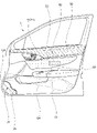
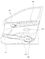
- the vehicle door lining 1 (hereinafter, also referred to as a door lining) of the first embodiment will be described with reference to FIGS. 1 to 8F.
- the vehicle door lining 1 is a vehicle interior component that decorates the inside of the vehicle door D, and is a group of parts attached to the door panel D1 that is the substrate of the vehicle door D. It is composed of.
- the door lining 1 is arranged above the armrest 2 that supports the arm of the seated person and the front portion of the armrest 2, and is an operation handle for opening and closing the vehicle door D. 3. It is provided with a pocket portion 4 arranged below the front portion of the armrest, and an operation panel 5 arranged on the upper surface of the armrest 2 for adjusting the opening and closing of the power window.
- the door panel D1 is mainly composed of an outer panel D2 and an inner panel D3 formed of a steel plate.
- a reinforcing member D4 extending in the front-rear direction of the seat is formed on the inner surface of the inner panel D3. Reinforcing members may be further formed on the inner surface of the outer panel D2 or the outer surface of the inner panel D3.
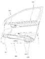
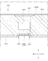
- the reinforcing member D4 has, for example, a vertical cross-sectional groove shape, and forms a closed cross-sectional structure together with the main body portion of the inner panel D3. Further, as shown in FIG. 3, the reinforcing member D4 extends from the front end portion of the door lining 1 toward the rear end portion while inclining downward.
- the door lining 1 is configured by coating a skin material 20 on a door lining base material 10 which is a substrate of the door lining 1.
- the door lining 1 has a front end portion of the door lining base material 10 rotatably attached to the vehicle body via a hinge 10a. Therefore, the connecting members of various electric parts provided on the door lining 1 extend toward the front end portion of the door lining 1.
- the connecting member is connected to a power source (power supply system) provided on the vehicle body.
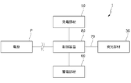
- the door lining 1 has a light emitting member 30 that emits light toward the inside of the vehicle, a decorative panel 40 that is irradiated by the light emitting member 30, and a power generation member 50 that supplies electricity to the light emitting member 30 in order to exert a lighting function in the vehicle.
- a lighting module includes a power storage member 60 for storing electricity, a light emitting member 30, a decorative panel 40, a power generation member 50, and a connection member 70 for electrically connecting each of the power storage member 60.
- the door lining 1 is provided with a control controller 80 that is electrically connected to the light emitting member 30, the decorative panel 40, the power generation member 50, and the power storage member 60 via the connecting member 70 to control the light emission of the light emitting member 30.
- the light emitting member 30, the decorative panel 40, the power generation member 50, the power storage member 60, and the control controller 80 are attached to each of the door lining base materials 10 at predetermined positions.
- the door lining base material 10 is a plate-shaped frame made of resin, and extends so as to be elongated in the front-rear direction of the vehicle.
- the door lining base material 10 is formed on the inner side surface of the vehicle, and is formed at a position above the armrest base material portion 11 which is the base material portion of the armrest 2 and the armrest base material portion 11, and is formed as a light emitting member 30 and decoration.
- An assembly portion 12 for assembling the panel 40 and a shock absorbing portion 13 formed on the outer side surface of the door lining base material 10 and arranged below the armrest base material portion 11 and projecting toward the door panel D1. And have.
- the assembling portion 12 is formed as a substantially rectangular concave portion, a light emitting member 30 is attached to the bottom of the assembling portion 12, and a decorative panel 40 is fitted in the opening of the assembling portion 12. ..
- the surface of the door lining 1 and the decorative panel 40 are formed so as to be substantially flush with each other.
- the shock absorbing unit 13 is a shock absorbing body provided between the door panel D1 and the door lining 1 in order to alleviate the impact applied to the occupant from the vehicle door D at the time of a side collision of the vehicle.
- the shock absorbing portion 13 is formed as a substantially circular convex portion, and is formed so as to be gradually narrowed from the door lining 1 toward the door panel D1. In other words, it is formed so as to project in a staircase pattern.
- the skin material 20 is made of a resin material (for example, TPO), a cloth (for example, PET material), genuine leather, or the like, and may cover the inner surface of the door lining base material 10. It is formed in a possible shape.
- the skin material 20 includes a first skin material 21 that covers a portion above the armrest base material portion 11 on the inner surface of the door lining base material 10 and a portion below the armrest base material portion 11. It has a second skin material 22 to be covered.
- the skin terminal portions of the first skin material 21 and the second skin material 22 are attached to the skin attachment portions provided on the door lining base material 10.
- the door lining 1 does not have to have the skin material 20.
- the light emitting member 30 is a planar light emitting body elongated in the front-rear direction of the sheet, and specifically, a light source 31 such as an LED lamp and light emitted from the light source 31. It is mainly composed of a light guide body 32 that guides the light source 32 and a light emitting panel 33 that emits the guided light evenly over the entire surface.
- the light emitting member 30 may be a planar light emitting body such as an LED display or an organic EL display.
- the light emitting member 30 is arranged at a substantially central portion of the door lining 1. Specifically, it is arranged between the power generation member 50 and the power storage member 60 in the vertical direction. A decorative panel 40 is arranged at a position inside the vehicle facing the light emitting member 30.
- the decorative panel 40 is a planar resin member exposed inside the vehicle, has light transmission property, and exhibits the function of decorative lighting.
- the decorative panel 40 has a light emitting region 41 on the surface of the panel, and can display a predetermined decorative pattern by being irradiated by the light emitting member 30. More specifically, the light emitting region 41 is formed with a "touch panel” as an information display screen. Then, while the light emitting member 30 is irradiating with light, the "touch panel” is lit in the light emitting region 41 and information is displayed. On the other hand, the "touch panel” is turned off while the light emitting member 30 is not irradiating light, and the decorative panel 40 is configured to be in harmony with the surface of the door lining 1.
- At least one of the still image information, the moving image information, and the character information is displayed on the "touch panel".
- various information on the “touch panel” it is possible to improve the comfort in the interior of the vehicle.
- information on the current time, weather, room temperature, and humidity is displayed as the information displayed on the "touch panel”.
- an operation button for operating the reclining mechanism and the height link mechanism of the vehicle seat S is displayed.
- existing operation buttons such as windows, car audios, and car navigation systems can be replaced with "touch panels" for display.
- the seated person can operate the "touch panel” depending on the mood and situation, and the information displayed on the "touch panel” can be switched, so that the comfort in the vehicle is improved.
- the number of parts can be reduced and the space inside the vehicle can be secured.
- the design is improved more than before.
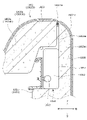
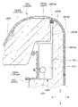
- the power generation member 50 is a film-shaped solar cell module, which is attached to the upper portion (upper end portion) of the door lining 1 and is attached along the inner surface of the door lining 1. Have been placed.
- the power generation member 50 is an organic thin-film type solar cell module, and as shown in FIG. 5, the solar cell 51, the sealing layer 52 for sealing the solar cell 51, and the sealing layer 52 are sealed. It is mainly composed of a power generator having a surface layer 53 provided on the surface side of the power generation member 50 with respect to the layer 52, and a resin film substrate 54 as a substrate of the power generation body.
- a plurality of power generators including the solar cell 51 are arranged (arranged so as to diffuse) on the film substrate 54 over substantially the entire area.
- the power generation member 50 may be a perovskite type solar cell module or the like, in addition to the organic thin film type. If it is a film-shaped solar cell module as described above, it can be shaped or bonded and attached according to the design shape of the door lining 1. Then, it is possible to realize a power generation member that is lighter and thinner than the conventional one.
- the solar cell 51 is an energy conversion element that absorbs light energy emitted from the sun and converts it into electricity, and is composed of a semiconductor such as silicon.
- the sealing layer 52 is formed by sealing the solar cell 51 with a resin adhesive.
- the surface layer 53 is formed by laminating a resin material having translucency (for example, ETFE (ethylene tetrafluoroethylene)). Therefore, the solar cell 51 can efficiently generate electricity. Further, a fine uneven shape is formed on the surface of the surface layer 53 by, for example, drawing. For example, a fine uneven shape having an arithmetic mean roughness Ra of 50 nm or more and 5 ⁇ m or less is formed. Therefore, the design of the surface of the power generation member 50 can be improved. In addition, scars and stains on the surface can be made inconspicuous.
- the power generation member 50 is arranged at the upper end portion of the door lining 1 and is attached while being curved along the surface of the skin material 20 of the door lining 1. Therefore, the film-shaped power generation member 50 can be suitably attached while following the surface of the door lining 1. Further, by attaching the power generation member 50 to a portion where sunlight is easily exposed, it is possible to efficiently generate power.
- a phosphorescent material may be laminated on the film substrate 54 at a position different from that of the solar cell 51 (power generator) to separately form a phosphorescent body that absorbs sunlight. Then, electricity can be suitably discharged from the power generation member 50. In addition, a new design can be added.
- the power storage member 60 is a plate-shaped storage battery that stores electricity generated by the power generation member 50 and supplies electricity to the light emitting member 30.
- the power storage member 60 is arranged below the light emitting member 30 and the power generation member 50, and is attached to the lower end portion of the armrest base material portion 11 in the door lining base material 10.
- the connecting member 70 is a film-shaped electric circuit (collecting sheet), and is formed by, for example, processing a conductive film substrate 70a and the surface of the film substrate 70a. It is mainly composed of the metal wiring 70b to be formed.
- the connection member 70 includes a first connection member 71 that connects the light emitting member 30, the power generation member 50, and the control controller 80, and a second connection member 72 that connects the light emitting member 30, the power storage member 60, and the control controller 80. ing.
- One end of the first connecting member 71 passes through a through hole 14 provided in the door lining base material 10 and is electrically connected to the lower end of the power generation member 50. Further, the other end of the first connecting member 71 is connected to the light emitting member 30 and the control controller 80 in a state of being sandwiched between the light emitting member 30 and the control controller 80. One end of the second connecting member 72 is sandwiched and connected between the light emitting member 30 and the control controller 80. Further, the other end of the second connecting member 72 is connected to the upper end of the power storage member 60.
- the connecting member 70 is composed of a film-shaped electric circuit, it can be arranged more compactly when compared with a conventional harness. Further, the weight of the door lining 1 can be reduced.
- the light emitting member 30 and the power storage member 60 are arranged above the reinforcing member D4 and the shock absorbing portion 13 in the side view of the door lining 1, and the reinforcing member D4 and the storage member 60 are arranged. It is arranged at a position avoiding the shock absorbing portion 13. Therefore, the work of attaching and detaching the light emitting member 30 and the power storage member 60 becomes easy.
- the light emitting member 30 and the power storage member 60 are arranged at overlapping positions in the vehicle front-rear direction and the thickness direction of the door lining 1, and are arranged at positions close to each other. Has been done. Further, the light emitting member 30 and the power storage member 60 are arranged at positions outside the vehicle with respect to the decorative panel 40. Therefore, the light emitting member 30 and the power storage member 60 can be arranged compactly, and electricity can be efficiently supplied from the power storage member 60 toward the light emitting member 30.
- the decorative panel 40 is arranged inside the vehicle with respect to the light emitting member 30, the power generation member 50, and the power storage member 60. Therefore, the design of the decorative panel 40 can be improved.
- the control controller 80 is a control device that comprehensively controls the lighting function of the door lining 1, and is attached to the back surface of the light emitting member 30.
- the control controller 80 is connected to the light emitting member 30 (decorative panel 40), the power generation member 50, and the power storage member 60, and the power generation member is based on the input of a predetermined user operation by the seated person.
- the electricity supply from the 50 or the power storage member 60 to the light emitting member 30 and the decorative panel 40 is controlled.
- a predetermined decoration pattern can be displayed in the light emitting area 41 of the decoration panel 40.
- a "touch panel" as an information display screen can be displayed in the light emitting area 41.
- the control controller 80 is electrically connected to a power source P (for example, an in-vehicle battery) provided on the vehicle body via a connection member (not shown), and is connected to the power supply P.
- the door lining 1 is electrically controlled while the electric supply is delivered.
- the control controller 80 receives power from the power source P when the amount of power generated by the power generation member 50 is less than a predetermined threshold value or when the amount of electricity stored by the power storage member 60 is less than a predetermined threshold value. Controls to supply electricity to electrical components. That is, when the amount of electricity generated by the power generation member 50 and the power storage member 60 is insufficient, power is supplied from the power source P on the vehicle body side.
- control controller 80 is the power generation member 50 or the power storage member when the power generation amount generated by the power generation member 50 is equal to or more than a predetermined threshold value or when the storage amount stored by the power storage member 60 is equal to or more than a predetermined threshold value. It is controlled to supply electricity from 60 toward the power source P and electric parts. That is, when the amount of electricity generated by the power generation member 50 and the power storage member 60 is sufficient, electricity is supplied to the power source P and the electric components on the vehicle body side.
- each component for exhibiting the lighting function can be arranged compactly, and the weight can be reduced as compared with the conventional case.
- the power generation member 50 can efficiently generate power.
- the door lining 101 of the second embodiment will be described with reference to FIG. 7.
- the description of the contents overlapping with the above-mentioned door lining 1 will be omitted.
- the door lining 101 is different from the door lining 1 in that the components for exhibiting the lighting function are mainly different from each other.
- the door lining 101 includes a light emitting member 130 having a light emitting region 132, a power generation member 150, a power storage member 160, a connection member 170, and a control controller 180 as lighting modules in order to exert a lighting function in the vehicle. There is.
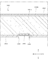
- the light emitting member 130, the power generation member 150, the power storage member 160, and the connecting member 170 are integrally formed in a film shape and integrally attached to the surface of the skin material 120 of the door lining 101.
- the light emitting member 130 is a film-shaped light emitting body, and is formed by printing an inorganic compound (for example, zinc sulfide) on a conductive film substrate 131 (for example, PET film substrate). The surface of the light emitting member 130 is formed as a light emitting region 132.
- the power generation member 150 is a film-shaped solar cell module, and is formed by laminating a laminate including a solar cell on the film substrate 131.
- the power storage member 160 is a film-shaped storage battery (for example, a film-type lithium ion secondary battery), and is formed by applying a gel-like or jelly-like electrolyte material on the film substrate 131.
- the connection member 170 is a film-shaped electric circuit, and the electric circuit is formed by providing metal wiring on the film substrate 131.
- the connecting member 170 has a first connecting member 171 that connects the light emitting member 130, the power generation member 150, and the control controller 180, and a second connecting member 172 that connects the light emitting member 130 and the power storage member 160.
- the control controller 180 is a microcontroller, which is arranged between the light emitting member 130 and the power generation member 150, and is attached to the back surface of the film substrate 131.
- each component for exhibiting the lighting function can be arranged more compactly, and the weight can be further reduced as compared with the conventional case.
- the module product can be easily attached to the vehicle door lining.
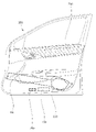
- the door lining 201 of the third embodiment includes a light emitting member 230, a power generation member 250, and a power storage member 260 as a lighting module.
- the light emitting member 230 and the power storage member 260 are arranged so as to be arranged in the front-rear direction of the vehicle (on the same horizontal plane) in order to be arranged compactly.
- the light emitting member 230 and the power storage member 260 are arranged below the reinforcing member D4 in the side view of the door lining 201, and are arranged at positions avoiding the reinforcing member D4.
- the light emitting member 230 and the power storage member 260 are arranged at a position in front of the shock absorbing unit 213 and at a position avoiding the shock absorbing unit 213. Therefore, the work of attaching and detaching the light emitting member 230 and the power storage member 260 becomes easy.
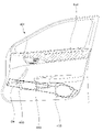
- the door lining 301 of the fourth embodiment includes a light emitting member 330, a power generation member 350, and a power storage member 360 as a lighting module.
- the light emitting member 330 and the power storage member 360 are arranged so as to be arranged in the front-rear direction of the vehicle (on the same horizontal plane) in order to be arranged compactly.
- the light emitting member 330 and the power storage member 360 are arranged at positions overlapping with the armrest 302 in the side view of the door lining 301. Further, the light emitting member 330 and the power storage member 360 are arranged at positions above the reinforcing member D4, and are arranged at positions avoiding the reinforcing member D4.
- the light emitting member 330 and the power storage member 360 are arranged at a position in front of the shock absorbing unit 313 and at a position avoiding the shock absorbing unit 313. Therefore, the work of attaching and detaching the light emitting member 330 and the power storage member 360 becomes easy.
- the door lining 401 of the fifth embodiment includes a light emitting member 430, a power generation member 450, and a power storage member 460 as lighting modules.
- the light emitting member 430 and the power storage member 460 are arranged at positions where at least a part of the reinforcing member D4 overlaps with the reinforcing member D4 in the side view of the door lining 401. Therefore, the light emitting member 430 and the power storage member 460 are protected by the reinforcing member D4.
- the entire light emitting member 430 and the power storage member 460 may be arranged at a position where they overlap with the reinforcing member D4.
- the light emitting member 430 and the power storage member 460 are arranged at a position in front of the shock absorbing unit 413 and at a position avoiding the shock absorbing unit 413. Therefore, the work of attaching and detaching the light emitting member 430 and the power storage member 460 becomes easy.
- the door lining 501 of the sixth embodiment includes a light emitting member 530, a power generation member 550, and a power storage member 560 as lighting modules.
- the light emitting member 530 is arranged above the reinforcing member D4 and the shock absorbing portion 513 in the side view of the door lining 501, and is arranged at a position avoiding the reinforcing member D4 and the shock absorbing portion 513. Therefore, the work of attaching and detaching the light emitting member 530 becomes easy.
- the power storage member 560 is arranged at a position where it overlaps with the reinforcing member D4, and is arranged at a position where it overlaps with the shock absorbing portion 513. Therefore, the power storage member 560 is protected by the reinforcing member D4.
- the power storage member 560 may be arranged at a position where it partially overlaps with the reinforcing member D4 and the impact absorbing unit 513.
- the door lining 601 of the seventh embodiment includes a light emitting member 630, a power generation member 650, and a power storage member 660 as lighting modules.
- the light emitting member 630 is arranged at a position overlapping with the reinforcing member D4 in the side view of the door lining 601 and is arranged at a position overlapping with the shock absorbing portion 613. Therefore, the light emitting member 630 is protected by the reinforcing member D4 and the impact absorbing portion 613.
- the light emitting member 630 may be arranged at a position where it partially overlaps with the reinforcing member D4 and the impact absorbing portion 613.
- the power storage member 660 is arranged at a position below the reinforcing member D4 and is arranged at a position in front of the shock absorbing portion 613. Therefore, the work of attaching and detaching the light emitting member 630 becomes easy.
- the door lining 701 of the eighth embodiment includes a light emitting member 730, a power generation member 750, and a power storage member 760 as lighting modules.
- the light emitting member 730 and the power storage member 760 are arranged above the reinforcing member D4 and the shock absorbing portion 713 in the side view of the door lining 701.
- the light emitting member 730 is arranged between the power generation member 750 and the power storage member 760 in the front-rear direction of the vehicle.
- the light emitting member 730 is provided at a position adjacent to the operation handle 703, and is arranged at a position overlapping the storage recess in which the operation handle 703 is housed. Therefore, the empty space around the operation handle 703 can be suitably illuminated.
- each component for exhibiting the lighting function can be arranged more compactly.
- the module product can be easily attached to the vehicle door lining.
- the light emitting member 730, the power generation member 750, and the power storage member 760 are arranged, even if an impact load is applied to the vehicle door D at the time of a side collision of the vehicle, the light emitting member 730, the power generation member 750, and the power storage member are arranged.
- the effect on 760 can be mitigated. More specifically, when an impact load is applied to the vehicle door D at the time of a side collision of the vehicle, the portion provided with the reinforcing member D4 and the impact absorbing portion 713 is most affected. At this time, since the light emitting member 730, the power generation member 750, and the power storage member 760 are arranged at positions avoiding the reinforcing member D4 and the impact absorbing portion 713, the influence of the impact load can be suppressed.
- the arrangement is close to the front end portion of the vehicle door D, and the arrangement is close to the power supply (power supply system) provided on the vehicle body.
- the lighting module can efficiently receive electricity from the vehicle body power supply, and the loss of electricity can be suppressed as much as possible.
- the vehicle door lining 1 includes a light emitting member 30, a power generation member 50, and a power storage member 60 in order to exert a lighting function in the vehicle, but is particularly limited. It may be applied to vehicle interior parts other than vehicle door linings without being used.
- vehicle interior parts such as an instrument panel, a console box, and a rear tray may include a light emitting member 30, a power generation member 50, and a power storage member 60.
- the power generation member 50 and the connecting member 70 are formed of a sheet-shaped or film-shaped member, but can be changed without particular limitation.
- the power generation member 50 may be a plate-shaped or panel-shaped solar cell.
- the connecting member 70 may be a conventional electric wiring or a harness in which a plurality of electric wirings are bundled.
- the power generation member 50 and the connection member 70 are made of a flexible material in the form of a sheet or a film.
- the light emitting member 30 and the power storage member 60 are also preferably formed of a sheet-like or film-like flexible material. More preferably, the light emitting member 30 has a light emitting region, and the decorative panel 40 may be made unnecessary by also having the function of the decorative panel 40.
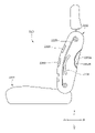
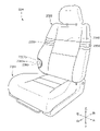
- the vehicle seat S1 realizes a seat capable of efficiently receiving the load applied from the occupant to the seat back at the time of a rear collision of the vehicle. More specifically, the vehicle seat S1 is provided with a seat back configured by adhering a skin material to a pad material, and is capable of efficiently receiving a load applied from an occupant to the seat back in the event of a rear collision of the vehicle. It will be realized.
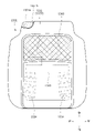
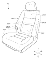
- the vehicle seat S1 is attached to the inside of the seat body having the seat cushion 1001 and the seat back 1002, and the seat back 1002, and the central portion 1002A of the seat back 1002 is normally positioned.
- a lumbar support 1030 that is movable to project toward the seated person
- a movable body 1040 that is attached to the inside of the seat body and is movable to project the side portion 1002B of the seat back 1002 toward the seated person from the normal position.
- (Side support member) and an actuating device 1050 (fluid supply device) that operates to move the lumbar support 1030 and the movable body 1040 are provided.
- the seat cushion 1001 is a seating portion that supports the seated person from below, and the pad material 1001a is placed on the cushion frame 1010 shown in FIG. 10 as a skeleton and covered with the skin material 1001b. It is composed of.
- the seat back 1002 is a backrest portion that supports the back of the seated person from behind, and the pad material 1002a is placed on the back frame 1020 shown in FIG. 10 as a skeleton, and the skin material 1002b is used. It is covered and configured.
- the seat back 1002 is composed of a central portion 1002A in the central portion in the seat width direction and left and right side portions 1002B (side bolster portions) outside the central portion 1002A in the seat width direction.
- left and right hanging grooves 1002C extending in the vertical direction are formed so as to separate the central portion 1002A and the left and right side portions 1002B.
- the cushion frame 1010 is composed of a rectangular frame-shaped body, and has a side frame 1011 arranged on the left and right sides and a plate-shaped pan frame 1012 erected on the front end portion of each side frame 1011.
- a plurality of support members 1014 that are hooked to the (erection frame), the rear connecting frame 1013 that connects the rear portions of the side frames 1011 to the pan frame 1012 and the rear connecting frame 1013, and extend in the front-rear direction of the seat.
- it is mainly composed of.
- the side frame 1011 is a plate-shaped frame that is long in the front-rear direction of the seat.
- a reclining device 1004 is attached to the rear portion of the side frame 1011 and a rail device 1006 is attached to the lower portion thereof via the height link device 1005.
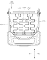
- the back frame 1020 has a rectangular frame-like body, and has an inverted U-shape that connects the back side frames 1021 arranged on the left and right sides and the upper end portions of the back side frames 1021.
- a plurality of wire members 1024 that are hooked to the upper frame 1022, the plate-shaped lower frame 1023 that connects the lower end portions of the backside frames 1021, and each backside frame 1021, and extend in a serpentine manner in the seat width direction. It is mainly composed of a (elastic wire) and a support plate 1025 that is held by a plurality of wire members 1024 and supports a seated person.
- the backside frame 1021 is a sheet metal member extending in the vertical direction and having a substantially C-shaped cross section, and its lower end portion is connected to the rear end portion of the side frame 1011 via a reclining device 1004. In the above configuration, the back frame 1020 can rotate relative to the cushion frame 1010.
- a lumbar support 1030 is attached to the front surface of the lower portion of the support plate 1025. Further, as shown in FIG. 10, left and right movable bodies 1040 are attached to the front surface of the lower portion of the left and right backside frames 1021.
- the lumbar support 1030 has a bag body (air cell) that swells when a fluid is sealed, and the seated side is filled with compressed air as a fluid. It swells to (protrudes from the normal position to the protruding position) and contracts (returns to the normal position) when the enclosed compressed air is discharged.
- the lumbar support 1030 is a member that supports the waist of the seated person, and is arranged between the pad material 1002a and the support plate 1025 in the central portion 1002A of the lower portion of the seat back 1002. Then, it is a member that is movable in order to project the central portion 1002A (pad material 1002a) toward the seated person.
- the lumbar support 1030 is attached to the front surface of the support plate 1025 in a folded state.
- the lumbar support 1030 has a long rectangular shape in the seat width direction, and is formed from a base member 1031 (base plate) supported by the support plate 1025 and a bag body 1032 supported by the front surface of the base member 1031. It is mainly composed.
- the bag body 1032 can bulge toward the front side of the seat by being filled with compressed air from the folded state.
- the movable body 1040 has a bag body (air cell), and is bulged toward the seated person (protruding from the normal position to the protruding position) by being filled with compressed air. It contracts (returns to the normal position) when the enclosed compressed air is discharged.
- the movable body 1040 is a side support member that supports the seated person from the side, and is arranged between the pad material 1002a and the back side frame 1021 in the side portion 1002B of the lower portion of the seat back 1002. ..
- the movable body 1040 is attached to the front surface of the backside frame 1021 in a folded state.
- the movable body 1040 has a substantially pentagonal shape that is long in the vertical direction, and is arranged at a position in front of the base member 1041 supported by the backside frame 1021 and the base member 1041 with respect to the base member 1041.
- a rotating member 1043 attached so as to be rotatable via a rotating shaft 1042, and a bag body 1044 arranged between the base member 1041 and the rotating member 1043 and supported on the front surface of the base member 1041. It is mainly composed of.
- the base member 1041 is attached to the front surface of the backside frame 1021 and extends along the front surface of the backside frame so as to project in the seat width direction.
- the rotation shaft 1042 is attached to the inner end portion in the seat width direction of the front surface of the base member 1041.
- the rotating member 1043 is rotatably attached to the base member 1041 in the front-rear direction of the seat, and by rotating toward the front of the seat, the side portion 1002B of the seat back 1002 is projected toward the front of the seat ( Can be extruded).
- the rotating member 1043 is arranged at a position closer to the base member 1041 when the seat back 1002 is in the normal position. It may be in a state of being urged to the base member 1041 side by an urging spring (urging member) (not shown).
- the bag body 1044 is supported by the base member 1041 and can be expanded toward the front side of the seat by being filled with compressed air, and the rotating member 1043 can be pushed out toward the front side of the seat. That is, the rotating member 1043 can be rotated forward of the seat.
- the protrusion direction and the protrusion amount of the seat back 1002 can be adjusted by inflating the bag body 1044.
- the actuating device 1050 is attached to the inside of the seat body and is a fluid for supplying compressed air to the lumbar support 1030 (bag body 1032) and the movable body 1040 (bag body 1044). It is a supply device.
- the actuating device 1050 is attached to the back surface of the air control unit 1051 attached to the outer surface of the backside frame 1021 and the back surface of the cushion frame 1010 (pan frame 1012) to supply (supply) and discharge (exhaust) compressed air. It is mainly composed of an air pump 1052 for the purpose and an air pipe 1053 connecting the air pump 1052 and the lumbar support 1030 (movable body 1040).
- the air control unit 1051 receives, for example, a predetermined user operation selection by a seated person and receives a predetermined control signal to supply compressed air to the bag bodies 1032 and 1044, or compressed air from the bag bodies 1032 and 1044.
- the air pump 1052 is controlled to discharge the air. By doing so, the movable range of the lumbar support 1030 and the movable body 1040 can be adjusted according to the physique of the seated person.
- the rear end portion of the movable body 1040 is the central portion 1002A of the seat back 1002. It is located on the front side of the seat from the seating surface of.
- a plurality of bag bodies 1044 are arranged on the front side of the seat with respect to the seating surface of the central portion 1002A of the seat back 1002. Therefore, it is possible to prevent wrinkles and duplication from occurring in the skin material 1002b of the seat back 1002.
- the movable body 1040 can be moved to move the side portion 1002B of the seat back 1002 from the "normal position" shown in FIG. 12A to the "protruding position” shown in FIG. 12B.
- FIG. 12A is a diagram showing a state in which the side portion 1002B of the seat back 1002 is in the “normal position”.
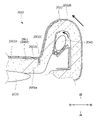
- FIG. 12B is a diagram showing a state in which the movable body 1040 protrudes forward of the seat and the side portion 1002B moves from the “normal position” to the “protruding position”. Specifically, by receiving the supply of compressed air from the actuating device 1050, the folded bag body 1044 expands and expands toward the front of the seat, and the rotating member 1043 is pushed toward the front of the seat to push the side. The portion 1002B moves to the front of the seat. As a result, the side portion 1002B moves to the "protruding position”.
- the compressed air inside the bag body 1044 is discharged by the actuating device 1050, so that the bag body 1044 in the inflated state contracts and the side portion 1002B is lowered to the rear of the seat. As a result, the side portion 1002B returns from the "protruding position" to the "normal position".
- the pad material 1002a and the skin material 1002b are adhered by the adhesive portion 1060.
- the adhesive portion 1060 is a portion provided with an adhesive, and is applied to the surface of the pad material 1002a continuously or at predetermined intervals along the vertical direction and the sheet width direction.
- the adhesive portion 1060 has a central adhesive portion 1061 arranged in the central portion 1002A of the seat back 1002, and a first side adhesive portion 1062 and a second side adhesive portion 1063 arranged in the side portion 1002B.
- the central adhesive portion 1061 is arranged at a position overlapping with the lumbar support 1030 in the sheet width direction and the vertical direction. Further, the central adhesive portion 1061 is arranged inside the left and right suspension grooves 1002C in the sheet width direction. More specifically, the central adhesive portion 1061 is arranged inside the left and right surface fragile portions 1070 formed on the surface of the pad material 1002a in the sheet width direction, and the left and right formed on the back surface of the pad material 1002a. It is arranged inside the fragile portion 1080 on the back surface of.
- the first side adhesive portion 1062 is arranged at a position overlapping with the movable body 1040 in the sheet width direction and the vertical direction.
- a plurality of first side adhesive portions 1062 are arranged at predetermined intervals in the sheet width direction and the vertical direction.
- the first side adhesive portion 1062 is arranged so as to avoid a portion of the side portion 1002B that is easily deformed by the movable body 1040 (specifically, the portion that is most easily deformed).
- the most easily deformable portion of the side portion 1002B corresponds to the front end portion of the side portion 1002B.
- the second side adhesive portion 1063 is arranged at a position overlapping with the movable body 1040 in the front-rear direction and the vertical direction of the seat.
- the second side adhesive portion 1063 is continuously arranged in the front-rear direction and the vertical direction of the sheet.
- the surface fragile portion 1070 is a groove formed on the surface of the pad material 1002a at a position inside the suspension groove 1002C and adjacent to the suspension groove 1002C.
- the back surface fragile portion 1080 is a groove formed in the back surface of the pad material 1002a at a position inside the suspension groove 1002C and adjacent to the suspension groove 1002C.
- the back surface fragile portion 1080 is arranged between the front surface fragile portion 1070 and the suspension groove 1002C in the sheet width direction.
- the front surface fragile portion 1070 and the back surface fragile portion 1080 are grooves (recesses) continuously formed along the vertical direction, but are not particularly limited and are formed at predetermined intervals along the vertical direction. It may be a groove (through groove).
- the adhesive portion 1060 is provided in the seat back 1002, the pad material 1002a and the skin material 1002b can be suitably adhered to each other. Further, since the "non-adhesive region" is formed in the seat back 1002 and the front surface fragile portion 1070 and the back surface fragile portion 1080 are formed, the load applied from the occupant to the seat back 1002 at the time of the rear surface collision of the vehicle can be efficiently received. It is possible to realize a vehicle seat that can be used. Specifically, the support plate 1025 can efficiently receive the load applied from the occupant to the seat back 1002 at the time of a rear surface collision.
- the vehicle seat S2 of the second embodiment will be described with reference to FIGS. 13 to 14A and B.
- the description of the contents overlapping with the vehicle seat S1 described above will be omitted.
- the vehicle seat S2 is provided with a blower device inside the seat body, and realizes a seat capable of appropriately securing a space for arranging a duct of the blower device. Further, the vehicle seat S2 realizes a seat capable of suppressing unintentional contact between the skin material and the duct in the seat body.
- the vehicle seat S2 includes a seat cushion 1101, a seat back 1102, and a blower device 1130 attached to the inside of the seat cushion 1101.
- the pad material 1101a and the skin material 1101b are adhered by the adhesive portion 1160.
- the blower device 1130 is attached to the bottom surface of the seat cushion 1101 (pad material 1101a).
- the blower device 1130 is configured to blow air from the blower main body 1131 toward the occupant (seat) through the duct 1132, the ventilation passage 1133 formed in the pad material 1101a, and the ventilation hole 1134.
- the duct 1132 is arranged at the rear end portion of the seat cushion 1101 (pad material 1101a) at the left side position, and extends along the vertical direction. More specifically, the duct 1132 is arranged at a position avoiding the pad material 1101a, and extends in the vertical direction so as to face the outer edge portion of the pad material 1101a. In other words, in the portion of the pad material 1101a corresponding to the duct 1132, a notch portion 1170 (duct relief portion) for not interfering with the duct 1132 is formed.
- the adhesive portion 1160 is a portion provided with an adhesive, and is applied to the surface of the pad material 1101a continuously or at intervals along the front-rear direction of the sheet and the width direction of the sheet.
- the adhesive portion 1160 has an upper surface adhesive portion 1161 applied to the upper surface of the pad material 1101a and a side adhesive portion 1162 applied to the outer surface of the pad material 1101a.
- the side adhesive portion 1162 is formed in the portion adjacent to (close to) the duct 1132 in the outer edge portion of the pad material 1101a.
- the pad material 1101a and the skin material 1101b can be suitably brought into close contact with each other around the duct 1132, and it is possible to prevent the skin material 1101b and the duct 1132 from coming into contact with each other unintentionally. That is, the skin material 1101b does not unintentionally shake and move at the peripheral position of the duct 1132 (for example, the position above the duct 1132), and the generation of abnormal noise due to the contact between the skin material 1101b and the duct 1132 is suppressed. can. It is also possible to secure the passage area of the duct 1132 and increase the passage area.
- a curved notch portion 1170 may be formed on the outer edge portion of the pad material 1101a. Then, it is preferable that the side bonding portion 1162 is provided in the notch portion 1170. By doing so, it is possible to further prevent the skin material 1101b and the duct 1132 from coming into contact with each other unintentionally.
- the vehicle seat S3 of the third embodiment will be described with reference to FIGS. 15 to 17D.
- the description of the contents overlapping with the above-mentioned vehicle seats S1 to S2 will be omitted.
- the vehicle seat S3 is provided with a blower device inside the seat body, and realizes a seat capable of ensuring the air conditioning capacity of the blower device regardless of the means for attaching the skin material.
- the vehicle seat S3 is provided with a detection sensor (seating sensor) inside the seat body, and realizes a seat capable of improving the detection accuracy by the detection sensor regardless of the means for attaching the skin material. be.
- the vehicle seat S3 includes a seat cushion 1201, a seat back 1202, a blower device 1230 mounted inside the seat cushion 1201, and a detection sensor 1240 mounted inside the seat cushion 1201. And have.
- the pad material 1201a and the skin material 1201b are adhered by the adhesive portion 1260.
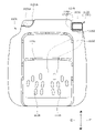
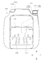
- the detection sensor 1240 is a planar pressure sensor that detects the seating pressure of a seated person, and is also referred to as a seating sensor. As shown in FIG. 16, the detection sensor 1240 is attached to the central portion of the cushion frame 1210 in the front-rear direction and the width direction of the seat. As shown in FIG. 17A, the detection sensor 1240 has a detection unit 1241 for detecting the seating pressure of a seated person and a transmission line 1242 for transmitting the detection data obtained by the detection unit 1241 toward a control device (not shown). And have. The detection unit 1241 is in contact with the bottom surface of the pad material 1201a.
- the detection sensor 1240 (detection unit 1241) is mounted on the cushion frame 1210 via the mounting bracket 1243. Further, the detection sensor 1240 is housed in a sensor storage recess 1244 formed on the bottom surface of the pad material 1201a.
- the detection sensor 1240 is arranged at a position different from the adhesive portion 1260 for adhering the pad material 1201a and the skin material 1201b in the sheet front-rear direction and the sheet width direction.
- the detection sensor 1240 is arranged at a position not facing the "adhesive region" where the adhesive portion 1260 is formed.
- the blower device 1230 is attached to the bottom surface of the cushion frame 1210 as shown in FIGS. 16, 17A and 17B.
- the blower device 1230 is configured to blow air toward the occupant through a duct 1232, a vent passage 1233, and a plurality of vents 1234.
- the duct 1232 is attached to the cushion frame 1210 via the mounting bracket 1235 and extends in the vertical direction.
- the ventilation passage 1233 is connected to the duct 1232 and is branched into a plurality of portions so as to extend in the front-rear direction of the seat and the width direction of the seat.
- the plurality of ventilation holes 1234 are connected to the ventilation passage 1233 and extend in the vertical direction.
- the ventilation passage 1233 is arranged at a position not facing the "adhesive region" in which the adhesive portion 1260 is formed. Further, as shown in FIG. 17B, the ventilation path 1233 is arranged at a position not facing the "adhesive region”.
- the duct 1232 and the ventilation passage 1233 are arranged at positions facing the "partially bonded region" formed by the bonding portions 1260 at intervals. That is, the duct 1232, the ventilation passage 1233, and the ventilation hole 1234 are arranged at positions avoiding the "completely bonded region" in which the bonded portion 1260 is continuously formed.
- the "partially bonded region" formed by the bonded portions 1260 at intervals is a high hardness region in which the pad material 1201a has a relatively high hardness. Therefore, it is possible to prevent the air-conditioned passage from being affected by the seating load of the occupant.
- the detection sensor 1240, the duct 1232, the ventilation passage 1233, and the ventilation hole 1234 may be arranged respectively.
- the detection sensor 1240 is arranged at a position facing the "adhesive region" where the adhesive portion 1260 is formed.
- the peripheral position of the detection sensor 1240 is arranged so as to face the "non-adhesive region" in which the adhesive portion 1260 is not formed.
- the peripheral position of the detection sensor 1240 may face the "partially bonded region”. By doing so, it is possible to ensure the detection accuracy by the detection sensor 1240.
- the ventilation path 1233 has a "completely bonded region” in which the bonded portions 1260 are continuously formed, or a “partially bonded region” in which the bonded portions 1260 are formed at intervals. It is located at the opposite position. Further, as shown in FIG. 17D, the duct 1232 is arranged at a position facing the "partially bonded region".
- the "completely bonded region” and “partially bonded region” are high hardness regions in which the pad material 1201a has a relatively high hardness. By doing so, it is possible to prevent the air-conditioning passage from being affected by the seating load of the occupant and the like, and it is possible to suppress a decrease in the air-conditioning capacity.
- the vehicle seat S4 of the fourth embodiment will be described with reference to FIGS. 18 to 20.
- the description of the contents overlapping with the above-mentioned vehicle seats S1 to S3 will be omitted.
- the vehicle seat S4 is provided with a blower device inside the seat body, and realizes a seat capable of ensuring the air conditioning capacity of the blower device regardless of the means for attaching the skin material.
- the vehicle seat S4 includes a seat cushion 1301, a seat back 1302, and a blower device 1330 attached to the inside of the seat cushion 1301.
- the pad material 1301a and the skin material 1301b are adhered by the adhesive portion 1360.
- the blower device 1330 is attached to the bottom surface of the cushion frame 1310 as shown in FIGS. 18 to 20.
- the blower device 1330 is configured to blow air toward the occupant through the duct 1332, the ventilation passage 1333, and the plurality of ventilation holes 1334.
- the plurality of ventilation holes 1334 are arranged so as to be arranged in the front-rear direction of the seat, and are arranged at intervals in the width direction of the seat.
- the front portion of the seat cushion 1301 in which the plurality of ventilation holes 1334 are formed is the "ventilation region”. Further, the rear portion of the seat cushion 1301 in which the ventilation holes 1334 are not formed is a “non-ventilated region”.
- the "ventilation region” in which the plurality of ventilation holes 1334 are formed in the seat cushion 1301 corresponds to the "non-adhesive region" in which the adhesive portion 1360 is not provided. It is configured in. Further, the “non-ventilated region” in which the ventilation holes 1334 are not formed in the seat cushion 1301 is configured to correspond to the "adhesive region” in which the adhesive portion 1360 is provided. Further, the area of the "ventilated region (non-adhesive region)" is larger than the area of the "non-ventilated region (adhesive region)".
- the air conditioning capacity of the blower device 1330 can be ensured regardless of the mounting means of the skin material 1301b (not affected by the adhesion). Further, the skin material 1301b can be suitably adhered and fixed to the pad material 1301a.
- the plurality of ventilation holes 1334 are arranged so as to be arranged in the front-rear direction of the seat, and are arranged at intervals in the width direction of the seat.
- the "adhesive region" formed by the adhesive portion 1360 also extends along the front-rear direction of the sheet and the width direction of the sheet.
- the "ventilation region" in which the plurality of ventilation holes 1334 are formed in the seat cushion 1301 corresponds to the "non-adhesive region", but the adhesive portions 1360 are formed at intervals. It may correspond to the "partially bonded area”. By doing so, the air conditioning capacity of the blower device 1330 can be ensured.
- the vehicle seat S5 of the fifth embodiment will be described with reference to FIGS. 21 to 22.
- the description of the contents overlapping with the above-mentioned vehicle seats S1 to S4 will be omitted.
- the vehicle seat S5 is provided with a detection sensor (seating sensor) inside the seat body, and realizes a seat capable of ensuring detection accuracy by the detection sensor regardless of the means for attaching the skin material. ..
- the vehicle seat S5 includes a seat cushion 1401, a seat back 1402, and a detection sensor 1440 mounted inside the seat cushion 1401.
- the pad material 1401a and the skin material 1401b are adhered by the adhesive portion 1460.
- the detection sensor 1440 is a planar pressure sensor that detects the seating pressure of the seated person.
- the detection sensor 1440 is mounted on a mounting bracket 1443 fixed on the vehicle body floor.
- the detection sensor 1440 is arranged so as to abut on the bottom surface of the pad material 1201a through the opening of the cushion frame 1410. More specifically, the detection sensor 1440 is housed in a sensor storage recess 1444 formed on the bottom surface of the pad material 1401a.
- the detection sensor 1440 By arranging the detection sensor 1440 on the bottom surface of the pad material 1401a as described above, the detection sensor 1440 can be arranged regardless of the mounting means of the skin material 1401b (not affected by adhesion). Further, the "adhesive region" in which the adhesive portion 1460 is formed is a high hardness region in which the pad material 1401a has a relatively high hardness. Therefore, the seating load by the occupant can be suitably transmitted to the detection sensor 1440, and the detection accuracy by the detection sensor 1440 can be ensured.
- the mounting bracket 1443 is fixed on the vehicle body floor, but is not particularly limited, and may be fixed to the cushion frame 1410 or the pad material 1401a.
- the mounting bracket 1443 is fixed to the pad material 1401a, it is preferable that the mounting bracket 1443 is fixed to the pad material 1401a with an adhesive.
- the mounting bracket 1443 may be integrated with the pad material 1401a by integral foam molding.
- the vehicle seat S6 of the sixth embodiment will be described with reference to FIGS. 23 to 25.
- the description of the contents overlapping with the above-mentioned vehicle seats S1 to S5 will be omitted.
- the vehicle seat S6 is provided with a seat heater inside the seat body, and even when the pad material and the skin material are fixed with an adhesive, the seat heater mounting state (adhesive state) is not affected. It is intended to realize a seat devised in this way.
- the vehicle seat S6 includes a seat cushion 1501, a seat back 1502, and a seat heater 1550 mounted inside the seat cushion 1501.
- the pad material 1501a and the skin material 1501b are adhered by the adhesive portion 1560.
- the seat heater 1550 is a planar heating element that warms the seat cushion 1501, and is attached to the surface of the pad material 1501a by an adhesive portion 1570.
- the "first adhesive region" to which the pad material 1501a and the skin material 1501b are adhered by the adhesive portion 1560 is a region wider in the sheet width direction than in the front-rear direction of the sheet. ..
- the "second adhesive region" to which the pad material 1501a and the sheet heater 1550 are adhered by the adhesive portion 1570 is a region wider in the front-rear direction of the sheet than in the width direction of the sheet.
- first adhesive region and the “second adhesive region” are arranged so as to partially overlap each other in the central portion of the seat cushion 1501.
- first adhesive region and the “second adhesive region” may be arranged so as not to overlap. That is, the "first adhesive region” formed by the adhesive portion 1560 may be formed while avoiding the “second adhesive region” formed by the adhesive portion 1570.
- the adhesive portion 1560 and the adhesive portion 1570 have different melting points due to the adhesive. More specifically, the melting point of the bonded portion 1560 is lower than the melting point of the bonded portion 1570.
- the adhesive state of the adhesive portion 1570 may be affected. not. That is, when the pad material 1501a and the skin material 1501b are adhered by the adhesive portion 1560, they are heated and melted at a temperature higher than the melting point of the adhesive portion 1560 and lower than the melting point of the adhesive portion 1570. It is possible to prevent the adhesive portion 1570 from being affected.
- the vehicle seat S7 of the seventh embodiment will be described with reference to FIGS. 26 to 27.
- the description of the contents overlapping with the above-mentioned vehicle seats S1 to S6 will be omitted.
- the vehicle seat S7 is provided with a seat heater inside the seat body, and realizes a seat in which the seat heater and the skin material can be efficiently attached to the pad material.
- the vehicle seat S7 includes a seat cushion 1601, a seat back 1602, and a seat heater 1650 mounted inside the seat cushion 1601.
- the pad material 1601a and the skin material 1601b are adhered by the adhesive portion 1660.
- the seat heater 1650 is a planar heating element that warms the seat cushion 1601 and is attached to the surface of the pad material 1601a.
- the adhesive portion 1660 is a portion provided with an adhesive and is applied to the surface of the pad material 1601a.
- the "adhesive region" provided with the adhesive portion 1660 is formed larger than the seat heater 1650, and is wider than the seat heater 1650 in the front-rear direction of the sheet and the width direction of the sheet.
- the "adhesive region” is arranged between the pad material 1601a and the seat heater 1650 in the vertical direction, and is arranged between the pad material 1601a and the skin material 1601b in the vertical direction.
- the adhesive portion 1660 can adhere both the seat heater 1650 and the skin material 1601b to the pad material 1601a. That is, in the "adhesive region" provided with the adhesive portion 1660, the portion overlapping with the seat heater 1650 is the portion for adhering the seat heater 1650 to the pad material 1601a. The portion of the "adhesive region" that does not overlap with the seat heater 1650 is the portion that adheres the skin material 1601b to the pad material 1601a.
- the seat heater 1650 and the skin material 1601b can be efficiently attached to the pad material 1601a.
- the seat heater 1650 and the skin material 1601b can be simultaneously bonded to the pad material 1601a in one work step (bonding work step).
- the seat heater 1650 may be attached to the back surface of the skin material 1601b by sewing. Even in that case, the seat heater 1650 and the skin material 1601b can be simultaneously adhered to the pad material 1601a in one work step.
- the vehicle seat S8 of the eighth embodiment will be described with reference to FIGS. 28 to 29A and B.
- the description of the contents overlapping with the above-mentioned vehicle seats S1 to S7 will be omitted.
- the vehicle seat S8 is provided with a seat heater inside the seat body, and is devised so as not to affect the thermostat of the seat heater even when the pad material and the skin material are fixed with an adhesive. It realizes the seat.
- the vehicle seat S8 includes a seat cushion 1701, a seat back 1702, and a seat heater 1750 attached to the inside of the seat cushion 1701.
- the pad material 1701a and the skin material 1701b are adhered by the adhesive portion 1760.
- the seat heater 1750 is attached to the surface of the pad material 1701a. As shown in FIG. 29A, the sheet heater 1750 is mounted on the sheet-shaped sheet base material 1751 and the sheet base material 1751, respectively, and is connected to the electric wire 1752 and the electric wire 1752 which are connected to a power source (not shown). It has a heater wire 1753 and a thermostat 1754 (temperature regulator) connected to the electric wire 1752 and the heater wire 1753.
- the thermostat 1754 is arranged at a position different from the inside of the seat cushion 1701 (pad material 1701a). Specifically, the thermostat 1754 is arranged outside the seat cushion 1701 and is arranged behind the seat cushion 1701. By doing so, even when the pad material 1701a and the skin material 1701b are adhered by heating and melting the adhesive portion 1760, the thermostat 1754 is not affected. That is, even when the pad material 1701a and the skin material 1701b are fixed with an adhesive, it is possible to realize a vehicle seat devised so as not to affect the thermostat 1754.
- the thermostat 1754 may be arranged at a position away from the adhesive portion 1760 inside the seat cushion 1701.
- the thermostat 1754 may be mounted on the cushion frame 1710 (side frame 1711) or on connecting clips 1715 provided on the plurality of elastic springs 1714. good.
- the vehicle seat S9 of the ninth embodiment will be described with reference to FIGS. 30, 31A to 31D.
- the description of the contents overlapping with the above-mentioned vehicle seats S1 to S8 will be omitted.
- the vehicle seat S9 is provided with an airbag device inside the seat body so that even when the pad material and the skin material are fixed with an adhesive, the swelling expansion of the airbag is not affected. It realizes a devised sheet.
- the vehicle seat S9 includes a seat cushion 1801, a seat back 1802, and a side airbag device 1850 mounted inside the side portion 1802B of the seat back 1802.
- the pad material 1802a and the skin material 1802b are adhered by the adhesive portion 1860.
- the side airbag device 1850 has a configuration in which the folded airbag 1852 bulges and expands toward the front side of the seat when an impact is applied from the side of the vehicle body.
- the side airbag device 1850 includes an airbag module 1851 provided inside the pad material 1802a in the side portion 1802B of the seat back 1802 and attached to the outer surface of the back side frame 1821.
- the airbag module 1851 is connected to an airbag 1852 that bulges and expands toward the front side of the seat, an inflator 1853 that supplies gas to the inside of the airbag 1852, and an inflator 1853, and supplies ignition power to the inflator 1853. It has a harness (not shown). The harness is connected to a vehicle battery (not shown) arranged on the vehicle body.
- the pad material 1802a is divided into an inner pad 1802ab and an outer pad 1802ac with the pad through hole 1802aa as a branch point.
- the epidermis material 1802b is divided into an inner epidermis material 1802bb and an outer epidermis material 1802bc with the epidermis cleavage portion 1802ba as a branch point and expanded. Therefore, the bulging and deploying direction of the airbag can be stabilized.
- the adhesive portion 1860 (adhesive region) is arranged at a position of the epidermis material 1802b so as to avoid the periphery of the epidermis open portion 1802ba and the epidermis open portion 1802ba. Then, even when the pad material 1802a and the skin material 1802b are fixed with an adhesive, it is possible to realize a vehicle seat devised so as not to affect the bulging expansion of the airbag 1852. ..
- the adhesive portion 1860 is formed along the extending direction (vertical direction) of the epidermis opening portion 1802ba, and is arranged at a position sandwiching the epidermis opening portion 1802ba in the sheet width direction.
- the epidermis material 1802b can be cured by the adhesive around the epidermis cleavage portion 1802ba.
- the adhesive portion 1860 is sewn by the guide member of the skin material 1802b. It is good that it is placed in a position that avoids the part where it is. By doing so, the deployment direction of the airbag 1852 can be made more stable.
- the guide member 1854a is padded by the adhesive portion 1860. It is preferable that it is adhered to the material 1802a. By doing so, the degree of freedom of the fixing method of the guide member 1854a can be increased. More specifically, in general, one end of the guide member 1854a is sewn to the skin cleavage portion 1802ba, and the other end is attached to the back frame 1820. On the other hand, in the present embodiment, the other end of the guide member 1854a is attached to the pad material 1802a instead of the back frame 1820. By doing so, the degree of freedom in arranging the guide member 1854a can be increased.
- the guide member 1854a is adhered by the adhesive portion 1860 over the entire surface from one end portion located on the epidermis cleavage portion 1802ba (fragile portion) side to the other end portion. good. By doing so, the guide member 1854a can be firmly attached to the pad material 1802a, and the deployment direction of the airbag 1852 can be more stabilized.
- the pad material 1802a and the guide member 1854a may be adhered by the adhesive portion 1860A, and the guide member 1854a and the skin material 1802b may be adhered by the adhesive portion 1860B.
- the guide member 1854 can be firmly attached to each of the pad material 1802a and the skin material 1802b.
- the deployment direction of the airbag 1852 can be further stabilized.
- the welding line and the epidermis cleavage portion 1802ba fragmente portion are formed at different positions. good. By doing so, even when the skin material 1802b composed of a plurality of skin pieces is adopted, the deployment direction of the airbag 1852 can be stabilized.
- the epidermis cleavage portion 1802ba can be formed by embossing or the like.
- the vehicle seat S10 of the tenth embodiment will be described with reference to FIGS. 32 and 33.
- the description of the contents overlapping with the above-mentioned vehicle seats S1 to S9 will be omitted.
- the vehicle seat S10 is equipped with an airbag device, and even when the pad material and the skin material are fixed with an adhesive, the seat is devised so as not to affect the expansion of the airbag. It will be realized.
- the vehicle seat S10 includes a seat cushion 1901, a seat back 1902, and an airbag device 1950 attached to a lower portion of the seat cushion.
- the pad material 1901a and the skin material 1901b are adhered by the adhesive portion 1960.
- the airbag device 1950 is configured such that when an impact is applied from the outside, the airbag 1952 in the folded state expands and expands upward.
- the airbag device 1950 includes an airbag 1952 attached to the lower portion of the seat cushion 1901.
- the pad material 1901a When the airbag 1952 expands and expands, the pad material 1901a is divided into a front pad 1901ab and a rear pad 1901ac with a slit groove 1901aa (slit hole) formed on the surface of the pad material 1901a as a branch point. ..
- the slit groove 1901aa is formed so as to be elongated in the seat width direction. That is, in the pad material 1901a, the portion where the slit groove 1901aa is formed is the portion where the adhesive portion 1960 is not provided.
- the vehicle seat S11 of the eleventh embodiment will be described with reference to FIGS. 34, 35A, and B.
- the description of the contents overlapping with the above-mentioned vehicle seats S1 to S10 will be omitted.
- the vehicle seat S11 is provided with a movable body inside the seat body, and is devised so as not to affect the movement of the movable body even when the pad material and the skin material are fixed with an adhesive. It realizes the seat.
- the vehicle seat S11 includes a seat cushion 2001, a seat back 2002, a lumbar support 2030 attached to the central portion 2002A of the seat back 2002, and a movable body 2040 (side support member) attached to the side portion 2002B of the seat back 2002. It is equipped with.
- the pad material 2002a and the skin material 2002b are adhered by the adhesive portion 2060.
- the movable body 2040 is arranged between the pad material 2002a and the backside frame 2021 in the side portion 2002B of the seat back 2002.
- the movable body 2040 is attached to the front surface of the backside frame 2021 in a folded state.
- the movable body 2040 can be moved to move the side portion 2002B from the "normal position" shown in FIG. 35A to the "protruding position" shown in FIG. 35B.
- the adhesive portion 2060 has a central adhesive portion 2061 arranged in the central portion 2002A of the seat back 2002 and a side adhesive portion 2062 arranged in the side portion 2002B.
- the adhesive portion 2060 is formed so as to straddle the central portion 2002A to the side portion 2002B in the seat back 2002. By doing so, it is possible to prevent wrinkles from being generated on the skin material 2002b when the side portion 2002B is displaced by the movable body 2040.
- the side adhesive portion 2062 is arranged at a position overlapping with the movable body 2040 in the sheet width direction and the vertical direction.
- the side adhesive portion 2062 is arranged so as to avoid a portion of the side portion 2002B that is easily deformed by the movable body 2040 (specifically, the portion most easily deformed).
- the most deformable portion of the side portion 2002B corresponds to the front end portion of the side portion 2002B.
- the adhesive portion 2060 is formed so as to avoid the skin terminal portion suspended in the suspension groove 2002C in the skin material 2002b.
- the side portion 2002B is displaced by the movable body 2040, the epidermis terminal portion becomes stretchable. That is, when the movable body 2040 moves, the side portion 2002B can be displaced more smoothly.
- the vehicle seat S12 of the twelfth embodiment will be described with reference to FIGS. 36 and 37.
- the description of the contents overlapping with the above-mentioned vehicle seats S1 to S11 will be omitted.
- the vehicle seat S12 is provided with a cushion length adjusting device inside the seat cushion so that the movement of the device is not affected even when the pad material and the skin material are fixed with an adhesive. It realizes a devised sheet.
- the vehicle seat S12 includes a seat cushion 2101, a seat back 2102, and a cushion length adjusting device 2140 attached to the front portion of the seat cushion 2101.
- the pad material 2101a and the skin material 2101b are adhered by the adhesive portion 2160.
- the cushion length adjusting device 2140 is a device capable of adjusting the front-rear length of the seat cushion 2101, and can be moved to move the seat cushion 2101 from the "normal position" to the "protruding position".
- the cushion length adjusting device 2140 has a link mechanism and a winding mechanism. When the seat cushion 2101 is in the "normal position", the link mechanism is folded and the take-up mechanism operates to wind the front end of the seat cushion 2101. When the seat cushion 2101 is in the "protruding position", the link mechanism is deployed and the take-up mechanism operates to extend the front end of the seat cushion 2101.
- the adhesive portion 2160 has an upper adhesive portion 2161 arranged on the upper surface of the seat cushion 2101 and a front adhesive portion 2162 arranged on the front surface of the seat cushion 2101.
- the upper adhesive portion 2161 is configured by continuously applying an adhesive.
- the front adhesive portion 2162 is configured by applying the adhesive discontinuously at intervals.
- the upper adhesive portion 2161 and the front adhesive portion 2162 extend long in the sheet width direction. By doing so, it is possible to prevent wrinkles and sagging from occurring in the skin material 2101b when the seat cushion 2101 is displaced by the cushion length adjusting device 2140.
- the cushion length adjusting device 2140 is not limited to the one having a link mechanism and a winding mechanism, and may have a slide mechanism. Even when the cushion length adjusting device 2140 has a slide mechanism, it is preferable not to apply an adhesive to the portion of the skin material 2101b where a stretch margin is required. By doing so, it is possible to prevent wrinkles and sagging from occurring in the skin material 2101b when the seat cushion 2101 is displaced.
- the vehicle seat S13 of the thirteenth embodiment will be described with reference to FIGS. 38 and 39.
- the description of the contents overlapping with the above-mentioned vehicle seats S1 to S12 will be omitted.
- the vehicle seat S13 is provided with a lumbar support inside the seat back, and is devised so as not to affect the movement of the lumbar support even when the pad material and the skin material are fixed with an adhesive. It realizes the seat.
- the vehicle seat S13 includes a seat cushion 2201, a seat back 2202, and a lumbar support 2230 attached to the inside of the seat back 2202.
- the pad material 2202a and the skin material 2202b are adhered by the adhesive portion 2260.
- the lumbar support 2230 is a member that supports the waist of the seated person, and is arranged on the back surface of the support plate 2225 in the central portion of the lower portion of the seat back 2202. Then, it is a member that is movable to project the support plate 2225 and the pad material 2202a toward the seated person.
- the adhesive portion 2260 is applied to the front surface of the seat back 2202, and is arranged at a predetermined interval in the vertical direction. Further, the adhesive portion 2260 extends long in the sheet width direction.
- the adhesive portion 2260 is arranged so as to avoid a portion of the seat back 2202 that is easily deformed by the movement of the lumbar support 2230 (specifically, the portion that is most easily deformed).
- the most deformable portion of the seat back 2202 corresponds to the central portion (top) of the lumbar support 2230.
- the adhesive portion 2260 is arranged at a position of the seat back 2202 that overlaps with the portion that is deformed by the movement of the lumbar support 2230 (specifically, the portion that is most deformed). good. Even in that case, by forming a "non-adhesive region" in the portion of the skin material 2202b that requires an extension margin, the seat back 2202 can be smoothly displaced when the lumbar support 2230 moves.
- the vehicle seat S14 of the 14th embodiment will be described with reference to FIG. 40.
- the description of the contents overlapping with the above-mentioned vehicle seats S1 to S13 will be omitted.
- the vehicle seat S14 is provided with a seat back movable device inside the seat back so that the movement of the seat back movable device is not affected even when the pad material and the skin material are fixed with an adhesive. It is intended to realize a seat devised in the above.
- the vehicle seat S14 includes a seat cushion 2301, a seat back 2302, and a seat back movable device 2340 attached to the inside of the seat back 2302.
- the pad material 2302a and the skin material 2302b are adhered by the adhesive portion 2360.
- the seat back movable device 2340 is a device capable of rotating the upper portion of the seat back 2302 forward. That is, the seat back 2302 is a break-action type seat back.
- the skin gather portion 2350 is formed at a position of the skin material 2302b which is a boundary portion between the upper portion and the lower portion of the seat back 2302.
- the skin gather portion 2350 is a portion wrinkled by, for example, sewing a part of the skin material.
- the adhesive portion 2360 is arranged so as to avoid the skin gather portion 2350 in the skin material 2302b.
- a vehicle interior product (vehicle seat) used in an automobile has been described as a specific example, but the interior product for a two-wheeled vehicle (motorcycle seat), a vehicle such as a train or a bus is not particularly limited. It can be used for interior products (vehicle seats). Alternatively, it can also be used for interior parts (vehicle seats) for vehicles such as airplanes and ships.
- the invention is described as an interior product for a vehicle (door lining for a vehicle), but it may be an invention for a method for manufacturing an interior product for a vehicle.
- a step of attaching a light emitting member that emits light toward the inside of the vehicle to a base material of an interior product for a vehicle a step of attaching a power generation member that is electrically connected to the light emitting member and supplies electricity to the light emitting member, and a step of emitting light.
- a step of attaching a power storage member that is electrically connected to a member and a power generation member and stores electricity
- a method of manufacturing an interior product for a vehicle including the step may be an invention of a step of attaching a power storage member that is electrically connected to a member and a power generation member and stores electricity.
- the power generation member is in the form of a sheet or a film and is arranged along the surface of the interior product for a vehicle. According to the above method, it is possible to manufacture an interior product for a vehicle capable of exerting a lighting function in the vehicle without supplying electricity from a power source of the vehicle body.
- the vehicle interior parts vehicle door lining
- the vehicle seats according to the present invention have been described.
- the above embodiment is merely an example for facilitating the understanding of the present invention, and does not limit the present invention.
- the present invention can be modified and improved without departing from the spirit thereof, and it goes without saying that the present invention includes an equivalent thereof.
- the arrangement and configuration of the light emitting member, the power generation member, and the power storage member described in the above embodiment are merely examples, and do not limit the present invention.
Landscapes
- Engineering & Computer Science (AREA)
- Mechanical Engineering (AREA)
- General Engineering & Computer Science (AREA)
- Arrangements Of Lighting Devices For Vehicle Interiors, Mounting And Supporting Thereof, Circuits Therefore (AREA)
- Seats For Vehicles (AREA)
- Vehicle Interior And Exterior Ornaments, Soundproofing, And Insulation (AREA)
Abstract
車体の電源から電気を供給されることがなくても、車内における照明機能を発揮することが可能な車両用内装品を提供する。 車両に取り付けられる車両用内装品は、車両用ドアライニング(1)であって、車両内に向かって発光する発光部材(30)と、発光部材(30)に電気的に接続され、発光部材(30)に電気を供給する発電部材(50)と、発光部材(30)及び発電部材(50)に電気的に接続され、電気を蓄える蓄電部材(60)とを備えている。発光部材(30)、発電部材(50)、及び蓄電部材(60)は、車両用ドアライニング(1)の車内側の面においてそれぞれ異なる位置に配置されている。また、発電部材(50)は、シート状又はフィルム状からなり、車両用ドアライニング(1)の面に沿って配置されている。
Description
本発明は、車両用内装品に係り、特に、車両の室内側に取り付けられ、車内に向かって発光する発光部材を備えた車両用内装品に関する。
従来、車両の室内側に取り付けられ、加飾部品として意匠性を備えるとともに実用的な機能を発揮する車両用加飾部品が知られている。
例えば、特許文献1には、車両用加飾部品の一例として、装飾照明として機能する一方で、意匠性向上の観点から消灯時には周辺部材と調和することが可能な車両用ドアライニングが提案されている。
例えば、特許文献1には、車両用加飾部品の一例として、装飾照明として機能する一方で、意匠性向上の観点から消灯時には周辺部材と調和することが可能な車両用ドアライニングが提案されている。
ところで、特許文献1のような車両用内装品において、電気自動車の開発、普及に伴い、車体の電源から電気を供給されることがなくても、車内における照明機能を発揮することができる技術が求められていた。
例えば、発光部材、発電部材及び蓄電部材を内蔵し、車体から電気の供給を受けることなく、自ら電気を発生させて照明機能を発揮することが可能な車両用内装品が求められていた。
なお、特許文献2に記載の車両用収納ボックスは、車内において照明(装飾照明)として機能するものではなく、また車両用内装品として意匠性を備えたものではないものの、ソーラーパネルと、LED基板と、蓄電池とを備えたモジュール品であることが開示されている。
例えば、発光部材、発電部材及び蓄電部材を内蔵し、車体から電気の供給を受けることなく、自ら電気を発生させて照明機能を発揮することが可能な車両用内装品が求められていた。
なお、特許文献2に記載の車両用収納ボックスは、車内において照明(装飾照明)として機能するものではなく、また車両用内装品として意匠性を備えたものではないものの、ソーラーパネルと、LED基板と、蓄電池とを備えたモジュール品であることが開示されている。
そのほか、照明機能を発揮するための各構成部品をコンパクトに配置し、大型化を抑制することが可能な技術が求められていた。
また、照明機能を発揮するにあたって発電部材を備えている場合には、発電部材が効率良く発電することが可能な技術が求められていた。
また、照明機能を発揮するにあたって発電部材を備えている場合には、発電部材が効率良く発電することが可能な技術が求められていた。
本発明は、上記の課題に鑑みてなされたものであり、本発明の目的は、車体の電源から電気が供給されることがなくても、車内における照明機能を発揮することが可能な車両用内装品を提供することにある。
また、本発明の他の目的は、照明機能を発揮するための構成部品をコンパクトに配置し、大型化を抑制することが可能な車両用内装品を提供することにある。
また、本発明の他の目的は、照明機能を発揮するにあたって発電部材を効率良く発電させることが可能な車両用内装品を提供することにある。
また、本発明の他の目的は、照明機能を発揮するための構成部品をコンパクトに配置し、大型化を抑制することが可能な車両用内装品を提供することにある。
また、本発明の他の目的は、照明機能を発揮するにあたって発電部材を効率良く発電させることが可能な車両用内装品を提供することにある。
前記課題は、本発明の車両用内装品によれば、車両に取り付けられる車両用内装品であって、前記車両内に向かって発光する発光部材と、前記発光部材と電気的に接続され、前記発光部材に電気を供給する発電部材と、前記発光部材及び前記発電部材と電気的に接続され、電気を蓄える蓄電部材と、を備え、前記発電部材が、シート状又はフィルム状からなり、前記車両用内装品の面に沿って配置されていること、により解決される。
上記構成により、車体の電源から電気が供給されなくても、車内における照明機能を発揮することが可能な車両用内装品を実現することができる。
詳しく述べると、車両用内装品が、発光部材と、発電部材と、蓄電部材と備えているため、自ら電気を発生させて電気を供給し、照明機能を発揮することが可能となる。
また、発電部材が、シート状又はフィルム状からなるため、照明機能を発揮するための構成部品をコンパクトに配置し、大型化を抑制することが可能となる。
また、シート状又はフィルム状の発電部材が車両用内装品の面に沿って配置されているため、例えば車両用内装品の外面が曲面部分を有する場合であっても、当該外面に追従させながら好適に発電部材を取り付けることができる。
このとき、前記車両用内装品は、車両用ドアの車内側に設けられる車両用ドアライニングであって、前記発光部材、前記発電部材、及び前記蓄電部材は、前記車両用ドアライニングの車内側の面においてそれぞれ異なる位置に配置されていると良い。
上記構成により、車両用ドアライニングにおいて発光部材、発電部材及び蓄電部材をコンパクトに配置し、車両用ドアライニングの厚さ方向において大型化を抑制することができる。
上記構成により、車両用ドアライニングにおいて発光部材、発電部材及び蓄電部材をコンパクトに配置し、車両用ドアライニングの厚さ方向において大型化を抑制することができる。
このとき、前記発電部材は、フィルム状の太陽電池モジュールであって、前記車両用内装品の上方部分に取り付けられ、前記発電部材及び前記蓄電部材よりも上方位置に配置されていると良い。
上記のように、太陽電池モジュールが車両用内装品において太陽光が直接当たり易い上方部分に取り付けられているため、太陽電池モジュールが効率良く発電することができる。
上記のように、太陽電池モジュールが車両用内装品において太陽光が直接当たり易い上方部分に取り付けられているため、太陽電池モジュールが効率良く発電することができる。
このとき、前記発光部材は、シート状又はフィルム状の発光体であって、前記蓄電部材は、シート状又はフィルム状の蓄電池であって、前記発光部材、前記発電部材、及び前記蓄電部材は、前記車両用内装品の車内側の面においてそれぞれ異なる位置に配置されていると良い。
また、前記車両用内装品は、前記発光部材、前記発電部材、及び前記蓄電部材をそれぞれ電気的に接続するための接続部材を備えており、前記接続部材が、シート状又はフィルム状の電気回路であると良い。
上記構成により、照明機能を発揮するための各構成部品を一層コンパクトに配置することができ、車両用ドアライニングの大型化を一層抑制することができる。また、車両用ドアライニングを軽量化することもできる。
また、前記車両用内装品は、前記発光部材、前記発電部材、及び前記蓄電部材をそれぞれ電気的に接続するための接続部材を備えており、前記接続部材が、シート状又はフィルム状の電気回路であると良い。
上記構成により、照明機能を発揮するための各構成部品を一層コンパクトに配置することができ、車両用ドアライニングの大型化を一層抑制することができる。また、車両用ドアライニングを軽量化することもできる。
このとき、前記発光部材、前記発電部材、前記蓄電部材、及び前記接続部材が、シート状又はフィルム状に一体的に形成され、前記車両用内装品の基材となる内装品基材の車内側の面に一体的に取り付けられると良い。
上記構成により、照明機能を発揮するための各構成部品を一体化したモジュール品とすることができ、当該モジュール品を車両用内装品に容易に取り付けることができる。
上記構成により、照明機能を発揮するための各構成部品を一体化したモジュール品とすることができ、当該モジュール品を車両用内装品に容易に取り付けることができる。
このとき、前記発電部材は、フィルム状の太陽電池モジュールであって、前記太陽電池モジュールは、太陽電池セルと、前記太陽電池セルを封止する封止層と、前記封止層よりも前記太陽電池モジュールの表面側に設けられる表面層と、を有しており、前記表面層が、透光性を有する樹脂材料から形成されており、前記表面層の表面には、微細な凹凸形状が形成されていると良い。
上記のように太陽電池モジュールの表面層が、透光性を有する樹脂材料から形成されているため、太陽電池モジュール(太陽電池セル)が効率良く発電することができる。
また、表面層の表面には、例えば絞り加工等によって微細な凹凸形状が形成されているため、太陽電池モジュールの表面の意匠性を向上できる。また、表面の傷跡や汚れを目立たなくできる。
上記のように太陽電池モジュールの表面層が、透光性を有する樹脂材料から形成されているため、太陽電池モジュール(太陽電池セル)が効率良く発電することができる。
また、表面層の表面には、例えば絞り加工等によって微細な凹凸形状が形成されているため、太陽電池モジュールの表面の意匠性を向上できる。また、表面の傷跡や汚れを目立たなくできる。
このとき、前記車両用内装品は、前記発光部材、前記発電部材、及び前記蓄電部材とそれぞれ接続され、前記発光部材の発光を制御する制御コントローラを備えていると良い。
また、前記制御コントローラは、車体に設けられた電源と接続され、前記車両用内装品の電気の供給を制御し、前記発電部材によって発電される発電量が所定の閾値未満であるとき、又は前記蓄電部材によって蓄えられる蓄電量が所定の閾値未満であるとき、前記電源から前記発光部材に向けて電気を供給するように制御し、前記発電部材によって発電される発電量が所定の閾値以上であるとき、又は前記蓄電部材によって蓄えられる蓄電量が所定の閾値以上であるとき、前記発電部材又は前記蓄電部材から前記発光部材に向けて電気を供給するように制御すると良い。
上記構成により、発電部材によって発電される発電量や、蓄電部材によって蓄えられる蓄電量に応じて発光部材の発光を好適に制御することができる。
また、発電量や蓄電量が不足しているときには車体側の電源から発光部材に向けて電気を供給することができる。発電量や蓄電量が十分にあるときには、発電部材や蓄電部材から車体側の電源や電気部品に向けて電気を供給することもできる。
このとき、前記車両用内装品は、前記車両用内装品の車内側の面に取り付けられ、前記発光部材によって照射される加飾パネルを備えており、前記発光部材は、上下方向又は車両前後方向において前記発電部材と前記蓄電部材の間に配置され、前記加飾パネルは、前記発光部材と対向する位置に配置されていると良い。
上記のように車両用内装品が加飾パネルを備えているため、自給自足によって電気を供給しながら車内における装飾照明を演出することができる。
上記のように車両用内装品が加飾パネルを備えているため、自給自足によって電気を供給しながら車内における装飾照明を演出することができる。
本発明によれば、自ら電気を供給し、車内における照明機能を発揮能な車両用内装品を実現することができる。また、照明機能を発揮するための構成部品をコンパクトに配置し、大型化を抑制できる。また、車両用内装品の外面に追従させながら好適に発電部材を取り付けることができる。
また本発明によれば、車両用ドアライニングの厚さ方向において大型化を抑制できる。
また本発明によれば、太陽電池モジュールが効率良く発電することができる。
また本発明によれば、車両用ドアライニングを軽量化することができる。
また本発明によれば、照明機能を発揮するための各構成部品を一体化したモジュール品とすることができる。
また本発明によれば、太陽電池モジュール(太陽電池セル)が効率良く発電することができる。
また本発明によれば、太陽電池モジュールの表面の意匠性を向上できる。また、太陽電池モジュールの表面の傷跡や汚れを目立たなくできる。
また本発明によれば、発電部材の発電量や、蓄電部材の蓄電量に応じて発光部材の発光を好適に制御することができる。
また本発明によれば、自ら電気を供給しながら車内における装飾照明を演出することができる。
以下、本発明に係る実施形態について図1~図40を参照して説明する。
本実施形態は、車両に取り付けられる車両用内装品(車両用ドアライニング)であって、車両内に向かって発光する発光部材と、発光部材と電気的に接続され、発光部材に電気を供給する発電部材と、発光部材及び発電部材と電気的に接続され、電気を蓄える蓄電部材とを備えており、発電部材がシート状又はフィルム状からなり、ドアライニングの面に沿って配置されていることを主な特徴とする車両用内装品の発明に関するものである。
また、車両用内装品のほか、車両用シートの発明に関するものもある。
なお、「車両前後方向(前後方向)」とは、車両の通常走行時の前後方向を意味し、「車両幅方向(幅方向)の車内側」とは、車両用ドアに対して車両の室内側を意味する。
<車両用ドアライニングの第1実施形態>
まず、第1実施形態の車両用ドアライニング1(以下、ドアライニングとも言う。)について、図1~図8Fに基づいて説明する。
車両用ドアライニング1は、図1、図2に示すように、車両用ドアDの車内側を装飾する車両用内装品であって、車両用ドアDの基板となるドアパネルD1に取り付けられる部品群によって構成されている。
例えば、ドアライニング1は、図2に示すように、着座者の腕部を支持するアームレスト2と、アームレスト2の前方部分よりも上方位置に配置され、車両用ドアDを開閉するための操作ハンドル3と、アームレストの前方部分よりも下方位置に配置されるポケット部4と、アームレスト2の上面に配置され、パワーウインドウの開閉を調整するための操作パネル5と、を備えている。
ドアパネルD1は、図1に示すように、鋼板から形成されたアウタパネルD2及びインナパネルD3から主に構成されている。
インナパネルD3の内側面には、シート前後方向に長尺に延びている補強部材D4が形成されている。なお、アウタパネルD2の内側面やインナパネルD3の外側面に補強部材がさらに形成されていても良い。
補強部材D4は、図1に示すように、例えば縦断面溝形状からなり、インナパネルD3の本体部とともに閉断面構造を形成している。また、補強部材D4は、図3に示すように、ドアライニング1の前端部から後端部に向かって下方傾斜しながら延びている。
インナパネルD3の内側面には、シート前後方向に長尺に延びている補強部材D4が形成されている。なお、アウタパネルD2の内側面やインナパネルD3の外側面に補強部材がさらに形成されていても良い。
補強部材D4は、図1に示すように、例えば縦断面溝形状からなり、インナパネルD3の本体部とともに閉断面構造を形成している。また、補強部材D4は、図3に示すように、ドアライニング1の前端部から後端部に向かって下方傾斜しながら延びている。
ドアライニング1は、図2~図4に示すように、ドアライニング1の基板となるドアライニング基材10に表皮材20を被覆して構成されている。
なお、ドアライニング1は、ドアライニング基材10の前端部がヒンジ10aを介して車体に対し回転可能に取り付けられている。
そのため、ドアライニング1に設けられた各種の電気部品の接続部材は、ドアライニング1の前端部に向かって延びている。そして、当該接続部材は、車体に設けられた電源(電源系統)と接続されている。
なお、ドアライニング1は、ドアライニング基材10の前端部がヒンジ10aを介して車体に対し回転可能に取り付けられている。
そのため、ドアライニング1に設けられた各種の電気部品の接続部材は、ドアライニング1の前端部に向かって延びている。そして、当該接続部材は、車体に設けられた電源(電源系統)と接続されている。
ドアライニング1は、車内における照明機能を発揮すべく、車両内に向かって発光する発光部材30と、発光部材30によって照射される加飾パネル40と、発光部材30に電気を供給する発電部材50と、電気を蓄える蓄電部材60と、発光部材30、加飾パネル40、発電部材50及び蓄電部材60それぞれを電気的に接続する接続部材70と、を照明モジュールとして備えている。
さらに、ドアライニング1は、発光部材30、加飾パネル40、発電部材50及び蓄電部材60と接続部材70を介して電気的に接続され、発光部材30の発光を制御する制御コントローラ80を備えている。
発光部材30、加飾パネル40、発電部材50、蓄電部材60及び制御コントローラ80は、それぞれドアライニング基材10の所定位置に取り付けられている。
さらに、ドアライニング1は、発光部材30、加飾パネル40、発電部材50及び蓄電部材60と接続部材70を介して電気的に接続され、発光部材30の発光を制御する制御コントローラ80を備えている。
発光部材30、加飾パネル40、発電部材50、蓄電部材60及び制御コントローラ80は、それぞれドアライニング基材10の所定位置に取り付けられている。
ドアライニング基材10は、図1、図3、図4に示すように、樹脂製の板状フレームであって、車両前後方向に長尺となるように延びている。
ドアライニング基材10は、その車内側の側面に形成され、アームレスト2の基材部となるアームレスト基材部11と、アームレスト基材部11よりも上方位置に形成され、発光部材30及び加飾パネル40を組み付けるための組み付け部12と、ドアライニング基材10の車外側の側面に形成され、アームレスト基材部11よりも下方位置に配置され、ドアパネルD1に向かって突出している衝撃吸収部13と、を備えている。
ドアライニング基材10は、その車内側の側面に形成され、アームレスト2の基材部となるアームレスト基材部11と、アームレスト基材部11よりも上方位置に形成され、発光部材30及び加飾パネル40を組み付けるための組み付け部12と、ドアライニング基材10の車外側の側面に形成され、アームレスト基材部11よりも下方位置に配置され、ドアパネルD1に向かって突出している衝撃吸収部13と、を備えている。
組み付け部12は、略矩形状の凹部として形成され、組み付け部12の底部には、発光部材30が取り付けられており、また組み付け部12の開口部には、加飾パネル40が嵌め込まれている。上記構成により、ドアライニング1の表面と、加飾パネル40とが略面一となるように形成される。
衝撃吸収部13は、車両の側突時に車両用ドアDから着座者に加わる衝撃を緩和すべく、ドアパネルD1とドアライニング1の間に設けられた衝撃吸収体である。
衝撃吸収部13は、具体的には、略円形状の凸部として形成され、ドアライニング1からドアパネルD1に向かって段階的に幅狭となるように形成されている。言い換えれば、階段状に突出するように形成されている。
上記構成により、車両用ドアDの変位量(変形量)に応じて適宜変形することで、衝突時に加わる荷重を抑制することができる。
衝撃吸収部13は、具体的には、略円形状の凸部として形成され、ドアライニング1からドアパネルD1に向かって段階的に幅狭となるように形成されている。言い換えれば、階段状に突出するように形成されている。
上記構成により、車両用ドアDの変位量(変形量)に応じて適宜変形することで、衝突時に加わる荷重を抑制することができる。
表皮材20は、図3、図4に示すように、樹脂材料(例えばTPO)、布地(例えばPET材料)、本皮革等からなり、ドアライニング基材10の車内側の面を被覆することが可能な形状に形成されている。
具体的には、表皮材20は、ドアライニング基材10の車内側の面においてアームレスト基材部11よりも上方部分を被覆する第1表皮材21と、アームレスト基材部11よりも下方部分を被覆する第2表皮材22と、有している。
第1表皮材21、第2表皮材22それぞれの表皮端末部は、ドアライニング基材10に設けられた表皮取り付け部に取り付けられている。
なお、ドアライニング1が表皮材20を有していなくても良い。
具体的には、表皮材20は、ドアライニング基材10の車内側の面においてアームレスト基材部11よりも上方部分を被覆する第1表皮材21と、アームレスト基材部11よりも下方部分を被覆する第2表皮材22と、有している。
第1表皮材21、第2表皮材22それぞれの表皮端末部は、ドアライニング基材10に設けられた表皮取り付け部に取り付けられている。
なお、ドアライニング1が表皮材20を有していなくても良い。
発光部材30は、図3、図4に示すように、シート前後方向に長尺な面状の発光体であって、具体的には、LEDランプ等の光源31と、光源31から出射する光を導く導光体32と、導かれた光を面全体にムラなく発光する発光パネル33と、から主に構成されている。
なお、発光部材30は、LEDディスプレイや有機ELディスプレイ等の面状発光体であっても良い。
なお、発光部材30は、LEDディスプレイや有機ELディスプレイ等の面状発光体であっても良い。
発光部材30は、ドアライニング1の略中央部分に配置されている。具体的には、上下方向において発電部材50と蓄電部材60の間に配置されている。
発光部材30に対向する車内側の位置には、加飾パネル40が配置されている。
発光部材30に対向する車内側の位置には、加飾パネル40が配置されている。
加飾パネル40は、図2~図4に示すように、車内側に露出する面状の樹脂部材であって、光透過性を有し、装飾照明の機能を発揮するものである。
具体的には、加飾パネル40は、そのパネル表面において発光領域41を有しており、発光部材30によって照射されることで、所定の加飾パターンを表示することができる。
より詳しく述べると、発光領域41には、情報表示画面としての「タッチパネル」が形成されている。そして、発光部材30が光を照射している間には、発光領域41に「タッチパネル」が点灯して情報が表示されるようになる。一方で、発光部材30が光を照射していない間には「タッチパネル」が消灯し、加飾パネル40がドアライニング1の表面と調和するように構成されている。
具体的には、加飾パネル40は、そのパネル表面において発光領域41を有しており、発光部材30によって照射されることで、所定の加飾パターンを表示することができる。
より詳しく述べると、発光領域41には、情報表示画面としての「タッチパネル」が形成されている。そして、発光部材30が光を照射している間には、発光領域41に「タッチパネル」が点灯して情報が表示されるようになる。一方で、発光部材30が光を照射していない間には「タッチパネル」が消灯し、加飾パネル40がドアライニング1の表面と調和するように構成されている。
ここで「タッチパネル」には、静止画情報、動画情報及び文字情報のうち、少なくとも一つの情報が表示される。「タッチパネル」に様々な情報が表示されることにより、車両の室内での快適性を向上させることが可能となる。
本実施形態においては、図2に示すように、「タッチパネル」に表示される情報として、現在の時刻、天気、室温及び湿度の情報が表示されている。また、車両用シートSのリクライニング機構及びハイトリンク機構を操作するための操作ボタンが表示されている。
なお、これら情報に限定されることなく、例えば、ウインドウ、カーオーディオ及びカーナビ等の既存の操作ボタンを「タッチパネル」に置き換え表示することもできる。
上記構成により、着座者が気分や状況によって「タッチパネル」を操作することや、「タッチパネル」に表示される情報を切り替えることができ、車両内での快適性が向上する。また、部品点数の削減や車内スペースの確保といった効果も得られる。さらには、従来よりもデザイン性が向上する。
発電部材50は、図2~図5に示すように、フィルム状の太陽電池モジュールであって、ドアライニング1の上方部分(上端部分)に取り付けられ、ドアライニング1の車内側の面に沿って配置されている。
具体的には、発電部材50は、有機薄膜型の太陽電池モジュールであって、図5に示すように、太陽電池セル51と、太陽電池セル51を封止する封止層52と、封止層52よりも発電部材50の表面側に設けられる表面層53とを有する発電体と、当該発電体の基板となる樹脂製のフィルム基板54と、から主に構成されている。
太陽電池セル51を含む発電体は、フィルム基板54上に略全体にわたって複数配置されている(拡散するように配置されている)。
なお、発電部材50は、有機薄膜型のほか、ペロブスカイト型の太陽電池モジュール等であっても良い。上記のようなフィルム状の太陽電池モジュールであれば、ドアライニング1の意匠形状に合わせて賦形又は貼り合わせて取り付けることができる。そして、従来よりも軽くて薄い発電部材を実現することができる。
太陽電池セル51は、太陽から放出される光エネルギーを吸収し、電気に変換するエネルギー変換素子であって、シリコン等の半導体から構成されている。
封止層52は、太陽電池セル51を樹脂製の接着剤によって封止することで形成されている。
表面層53は、透光性を有する樹脂材料(例えば、ETFE(エチレンテトラフルオロエチレン))を積層することで形成されている。そのため、太陽電池セル51が効率良く発電することができる。
また、表面層53の表面には、例えば絞り加工等によって微細な凹凸形状が形成されている。例えば、算術平均粗さRaが50nm以上5μm以下の微細な凹凸形状が形成されている。そのため、発電部材50の表面の意匠性を向上できる。また、表面の傷跡や汚れを目立たなくできる。
封止層52は、太陽電池セル51を樹脂製の接着剤によって封止することで形成されている。
表面層53は、透光性を有する樹脂材料(例えば、ETFE(エチレンテトラフルオロエチレン))を積層することで形成されている。そのため、太陽電池セル51が効率良く発電することができる。
また、表面層53の表面には、例えば絞り加工等によって微細な凹凸形状が形成されている。例えば、算術平均粗さRaが50nm以上5μm以下の微細な凹凸形状が形成されている。そのため、発電部材50の表面の意匠性を向上できる。また、表面の傷跡や汚れを目立たなくできる。
発電部材50は、ドアライニング1の上端部分に配置され、ドアライニング1の表皮材20の表面に沿って湾曲しながら貼り付けられている。
そのため、ドアライニング1の表面に追従させながら、好適にフィルム状の発電部材50を取り付けることができる。また、太陽光が直接当たり易い部分に発電部材50を取り付けることで、効率良く発電することができる。
そのため、ドアライニング1の表面に追従させながら、好適にフィルム状の発電部材50を取り付けることができる。また、太陽光が直接当たり易い部分に発電部材50を取り付けることで、効率良く発電することができる。
なお、フィルム基板54上において太陽電池セル51(発電体)とは異なる位置に蓄光材料を積層し、太陽光を吸収する蓄光体を別途形成しても良い。そうすれば、発電部材50から好適に電気を放出することができる。また、新たな意匠性を付与することもできる。
蓄電部材60は、図3、図4に示すように、板状の蓄電池であって、発電部材50によって発電された電気を蓄え、発光部材30に向けて電気を供給するものである。
蓄電部材60は、発光部材30及び発電部材50よりも下方位置に配置されており、ドアライニング基材10においてアームレスト基材部11の下端部に取り付けられている。
蓄電部材60は、発光部材30及び発電部材50よりも下方位置に配置されており、ドアライニング基材10においてアームレスト基材部11の下端部に取り付けられている。
接続部材70は、図4に示すように、フィルム状の電気回路(集電用シート)であって、例えば、導電性を有するフィルム基板70aと、フィルム基板70aの表面を加工処理することで形成される金属配線70bと、から主に構成されている。
接続部材70は、発光部材30、発電部材50及び制御コントローラ80を接続する第1接続部材71と、発光部材30、蓄電部材60及び制御コントローラ80を接続する第2接続部材72と、を有している。
接続部材70は、発光部材30、発電部材50及び制御コントローラ80を接続する第1接続部材71と、発光部材30、蓄電部材60及び制御コントローラ80を接続する第2接続部材72と、を有している。
第1接続部材71の一端部は、ドアライニング基材10に設けられた貫通孔14を通過して発電部材50の下端部に電気的に接続されている。
また、第1接続部材71の他端部は、発光部材30及び制御コントローラ80の間に挟まれた状態で、発光部材30及び制御コントローラ80と接続されている。
第2接続部材72の一端部は、発光部材30及び制御コントローラ80の間に挟まれて接続されている。
また、第2接続部材72の他端部は、蓄電部材60の上端部に接続されている。
また、第1接続部材71の他端部は、発光部材30及び制御コントローラ80の間に挟まれた状態で、発光部材30及び制御コントローラ80と接続されている。
第2接続部材72の一端部は、発光部材30及び制御コントローラ80の間に挟まれて接続されている。
また、第2接続部材72の他端部は、蓄電部材60の上端部に接続されている。
上記構成において、図4に示すように、接続部材70がフィルム状の電気回路から構成されているため、従来のハーネスと比較したときにコンパクトに配置することができる。また、ドアライニング1を軽量化することもできる。
また上記構成において、図3に示すように、発光部材30及び蓄電部材60は、ドアライニング1の側面視において補強部材D4及び衝撃吸収部13よりも上方位置に配置されており、補強部材D4及び衝撃吸収部13を避けた位置に配置されている。
そのため、発光部材30及び蓄電部材60の着脱作業が容易になる。
そのため、発光部材30及び蓄電部材60の着脱作業が容易になる。
また上記構成において、図3、図4に示すように、発光部材30と蓄電部材60は、車両前後方向及びドアライニング1の厚さ方向において重なる位置に配置されており、互いに近接した位置に配置されている。また、発光部材30及び蓄電部材60は、加飾パネル40よりも車外側の位置に配置されている。
そのため、発光部材30及び蓄電部材60をコンパクトに配置し、蓄電部材60から発光部材30に向けて効率良く電気を供給することができる。
そのため、発光部材30及び蓄電部材60をコンパクトに配置し、蓄電部材60から発光部材30に向けて効率良く電気を供給することができる。
また上記構成において、図3、図4に示すように、加飾パネル40は、発光部材30、発電部材50、及び蓄電部材60よりも車内側に配置されている。そのため、加飾パネル40による意匠性を向上させることができる。
制御コントローラ80は、図3、図4に示すように、ドアライニング1の照明機能の電気制御を総合的に行う制御装置であって、発光部材30の裏面に取り付けられている。
制御コントローラ80は、図6に示すように、発光部材30(加飾パネル40)、発電部材50及び蓄電部材60と接続されており、着座者による所定のユーザ操作の入力に基づいて、発電部材50又は蓄電部材60から発光部材30及び加飾パネル40への電気供給を制御する。
そうすることで、加飾パネル40の発光領域41に所定の加飾パターンを表示することができる。あるいは、発光領域41に情報表示画面としての「タッチパネル」を表示することができる。
制御コントローラ80は、図6に示すように、発光部材30(加飾パネル40)、発電部材50及び蓄電部材60と接続されており、着座者による所定のユーザ操作の入力に基づいて、発電部材50又は蓄電部材60から発光部材30及び加飾パネル40への電気供給を制御する。
そうすることで、加飾パネル40の発光領域41に所定の加飾パターンを表示することができる。あるいは、発光領域41に情報表示画面としての「タッチパネル」を表示することができる。
また、制御コントローラ80は、図6に示すように、不図示の接続部材を介して車体に設けられた電源P(例えば、車載バッテリ)と電気的に接続されており、電源Pとの間で電気供給の受け渡しをしながら、ドアライニング1の電気制御を行っている。
具体的には、制御コントローラ80は、発電部材50によって発電される発電量が所定の閾値未満であるとき、又は蓄電部材60によって蓄えられる蓄電量が所定の閾値未満であるときに、電源Pから電気部品に向けて電気を供給するように制御する。
つまり、発電部材50及び蓄電部材60による電気量が不足している場合には、車体側の電源Pから電力供給を受けることとしている。
また、制御コントローラ80は、発電部材50によって発電される発電量が所定の閾値以上であるとき、又は蓄電部材60によって蓄えられる蓄電量が所定の閾値以上であるときに、発電部材50又は蓄電部材60から電源Pや電気部品に向けて電気を供給するように制御する。
つまり、発電部材50及び蓄電部材60による電気量が十分にある場合には、車体側の電源Pや電気部品に電気供給を行うこととしている。
以上の構成により、車体の電源Pから電気が供給されなくても、車内における照明機能を発揮することが可能なドアライニング1を実現できる。
また、照明機能を発揮するための各構成部品をコンパクトに配置し、従来よりも軽量化を図ることが可能となる。また、発電部材50を効率良く発電させることもできる。
また、照明機能を発揮するための各構成部品をコンパクトに配置し、従来よりも軽量化を図ることが可能となる。また、発電部材50を効率良く発電させることもできる。
<第2実施形態>
次に、第2実施形態のドアライニング101について、図7に基づいて説明する。
なお、上述のドアライニング1と重複する内容については説明を省略する。
ドアライニング101は、ドアライニング1と比較して、照明機能を発揮するための構成部品の構成が主に異なっている。
次に、第2実施形態のドアライニング101について、図7に基づいて説明する。
なお、上述のドアライニング1と重複する内容については説明を省略する。
ドアライニング101は、ドアライニング1と比較して、照明機能を発揮するための構成部品の構成が主に異なっている。
ドアライニング101は、車内における照明機能を発揮すべく、発光領域132を有する発光部材130と、発電部材150と、蓄電部材160と、接続部材170と、制御コントローラ180と、を照明モジュールとして備えている。
そして、発光部材130、発電部材150、蓄電部材160、及び接続部材170が、フィルム状に一体的に形成され、ドアライニング101の表皮材120の表面に一体的に取り付けられている。
そして、発光部材130、発電部材150、蓄電部材160、及び接続部材170が、フィルム状に一体的に形成され、ドアライニング101の表皮材120の表面に一体的に取り付けられている。
発光部材130は、フィルム状の発光体であって、導電性を有するフィルム基板131(例えばPETフィルム基板)上に無機化合物(例えば硫化亜鉛)を印刷することで形成されている。そして、発光部材130の表面が発光領域132として形成されている。
発電部材150は、フィルム状の太陽電池モジュールであって、上記フィルム基板131上に太陽電池セルを含む積層体を積層することで形成されている。
蓄電部材160は、フィルム状の蓄電池(例えばフィルム型リチウムイオン二次電池)であって、上記フィルム基板131上にゲル状又はゼリー状の電解質素材を塗布することで形成されている。
接続部材170は、フィルム状の電気回路であって、上記フィルム基板131上に金属配線を設けることで電気回路を構成している。
発電部材150は、フィルム状の太陽電池モジュールであって、上記フィルム基板131上に太陽電池セルを含む積層体を積層することで形成されている。
蓄電部材160は、フィルム状の蓄電池(例えばフィルム型リチウムイオン二次電池)であって、上記フィルム基板131上にゲル状又はゼリー状の電解質素材を塗布することで形成されている。
接続部材170は、フィルム状の電気回路であって、上記フィルム基板131上に金属配線を設けることで電気回路を構成している。
接続部材170は、発光部材130、発電部材150及び制御コントローラ180を接続する第1接続部材171と、発光部材130及び蓄電部材160を接続する第2接続部材172と、を有している。
なお、制御コントローラ180は、マイクロコントローラであって、発光部材130及び発電部材150の間に配置されており、フィルム基板131の裏面に採り付けられている。
なお、制御コントローラ180は、マイクロコントローラであって、発光部材130及び発電部材150の間に配置されており、フィルム基板131の裏面に採り付けられている。
上記構成であっても、車体の電源から電気が供給されなくても、車内における照明機能を発揮することが可能なドアライニングを実現できる。
また、照明機能を発揮するための各構成部品を一層コンパクトに配置し、従来よりも一層軽量化を図ることが可能となる。また、上記モジュール品を車両用ドアライニングに容易に取り付けることができる。
また、照明機能を発揮するための各構成部品を一層コンパクトに配置し、従来よりも一層軽量化を図ることが可能となる。また、上記モジュール品を車両用ドアライニングに容易に取り付けることができる。
<第3~第8第実施形態>
次に、第3~第8実施形態のドアライニング201、301、401、501、601、701について、図8A~図8Fに基づいて説明する。
第3~第8実施形態のドアライニングでは、ドアライニング1と比較して、発光部材及び蓄電部材の配置が異なっている。
なお、加飾パネル、接続部材及び制御コントローラについては図示及び説明を省略する。
次に、第3~第8実施形態のドアライニング201、301、401、501、601、701について、図8A~図8Fに基づいて説明する。
第3~第8実施形態のドアライニングでは、ドアライニング1と比較して、発光部材及び蓄電部材の配置が異なっている。
なお、加飾パネル、接続部材及び制御コントローラについては図示及び説明を省略する。
第3実施形態のドアライニング201は、図8Aに示すように、発光部材230と、発電部材250と、蓄電部材260と、を照明モジュールとして備えている。
発光部材230及び蓄電部材260は、コンパクトに配置すべく、車両前後方向に並ぶように(同一水平面上に)配置されている。
発光部材230及び蓄電部材260は、ドアライニング201の側面視において補強部材D4よりも下方位置に配置されており、補強部材D4を避けた位置に配置されている。
また、発光部材230及び蓄電部材260は、衝撃吸収部213よりも前方位置に配置されており、衝撃吸収部213を避けた位置に配置されている。
そのため、発光部材230及び蓄電部材260の着脱作業が容易になる。
発光部材230及び蓄電部材260は、コンパクトに配置すべく、車両前後方向に並ぶように(同一水平面上に)配置されている。
発光部材230及び蓄電部材260は、ドアライニング201の側面視において補強部材D4よりも下方位置に配置されており、補強部材D4を避けた位置に配置されている。
また、発光部材230及び蓄電部材260は、衝撃吸収部213よりも前方位置に配置されており、衝撃吸収部213を避けた位置に配置されている。
そのため、発光部材230及び蓄電部材260の着脱作業が容易になる。
第4実施形態のドアライニング301は、図8Bに示すように、発光部材330と、発電部材350と、蓄電部材360と、を照明モジュールとして備えている。
発光部材330及び蓄電部材360は、コンパクトに配置すべく、車両前後方向に並ぶように(同一水平面上に)配置されている。
発光部材330及び蓄電部材360は、ドアライニング301の側面視においてアームレスト302と重なる位置に配置されている。
また、発光部材330及び蓄電部材360は、補強部材D4よりも上方位置に配置されており、補強部材D4を避けた位置に配置されている。
また、発光部材330及び蓄電部材360は、衝撃吸収部313よりも前方位置に配置されており、衝撃吸収部313を避けた位置に配置されている。
そのため、発光部材330及び蓄電部材360の着脱作業が容易になる。
発光部材330及び蓄電部材360は、コンパクトに配置すべく、車両前後方向に並ぶように(同一水平面上に)配置されている。
発光部材330及び蓄電部材360は、ドアライニング301の側面視においてアームレスト302と重なる位置に配置されている。
また、発光部材330及び蓄電部材360は、補強部材D4よりも上方位置に配置されており、補強部材D4を避けた位置に配置されている。
また、発光部材330及び蓄電部材360は、衝撃吸収部313よりも前方位置に配置されており、衝撃吸収部313を避けた位置に配置されている。
そのため、発光部材330及び蓄電部材360の着脱作業が容易になる。
第5実施形態のドアライニング401は、図8Cに示すように、発光部材430と、発電部材450と、蓄電部材460と、を照明モジュールとして備えている。
発光部材430及び蓄電部材460は、ドアライニング401の側面視において補強部材D4と少なくとも一部が重なる位置に配置されている。
そのため、発光部材430及び蓄電部材460が補強部材D4によって保護される。なお、発光部材430及び蓄電部材460の全体が、補強部材D4と重なる位置に配置されていても良い。
また、発光部材430及び蓄電部材460は、衝撃吸収部413よりも前方位置に配置されており、衝撃吸収部413を避けた位置に配置されている。
そのため、発光部材430及び蓄電部材460の着脱作業が容易になる。
発光部材430及び蓄電部材460は、ドアライニング401の側面視において補強部材D4と少なくとも一部が重なる位置に配置されている。
そのため、発光部材430及び蓄電部材460が補強部材D4によって保護される。なお、発光部材430及び蓄電部材460の全体が、補強部材D4と重なる位置に配置されていても良い。
また、発光部材430及び蓄電部材460は、衝撃吸収部413よりも前方位置に配置されており、衝撃吸収部413を避けた位置に配置されている。
そのため、発光部材430及び蓄電部材460の着脱作業が容易になる。
第6実施形態のドアライニング501は、図8Dに示すように、発光部材530と、発電部材550と、蓄電部材560と、を照明モジュールとして備えている。
発光部材530は、ドアライニング501の側面視において補強部材D4及び衝撃吸収部513よりも上方位置に配置されており、補強部材D4及び衝撃吸収部513を避けた位置に配置されている。
そのため、発光部材530の着脱作業が容易になる。
また、蓄電部材560は、補強部材D4と重なる位置に配置されており、かつ、衝撃吸収部513と重なる位置に配置されている。
そのため、蓄電部材560が補強部材D4によって保護される。なお、蓄電部材560が、補強部材D4及び衝撃吸収部513と一部重なる位置に配置されていても良い。
発光部材530は、ドアライニング501の側面視において補強部材D4及び衝撃吸収部513よりも上方位置に配置されており、補強部材D4及び衝撃吸収部513を避けた位置に配置されている。
そのため、発光部材530の着脱作業が容易になる。
また、蓄電部材560は、補強部材D4と重なる位置に配置されており、かつ、衝撃吸収部513と重なる位置に配置されている。
そのため、蓄電部材560が補強部材D4によって保護される。なお、蓄電部材560が、補強部材D4及び衝撃吸収部513と一部重なる位置に配置されていても良い。
第7実施形態のドアライニング601は、図8Eに示すように、発光部材630と、発電部材650と、蓄電部材660と、を照明モジュールとして備えている。
発光部材630は、ドアライニング601の側面視において補強部材D4と重なる位置に配置されており、かつ、衝撃吸収部613と重なる位置に配置されている。
そのため、発光部材630が補強部材D4及び衝撃吸収部613によって保護される。なお、発光部材630が、補強部材D4及び衝撃吸収部613と一部重なる位置に配置されていても良い。
また、蓄電部材660は、補強部材D4よりも下方位置に配置されており、かつ、衝撃吸収部613よりも前方位置に配置されている。
そのため、発光部材630の着脱作業が容易になる。
発光部材630は、ドアライニング601の側面視において補強部材D4と重なる位置に配置されており、かつ、衝撃吸収部613と重なる位置に配置されている。
そのため、発光部材630が補強部材D4及び衝撃吸収部613によって保護される。なお、発光部材630が、補強部材D4及び衝撃吸収部613と一部重なる位置に配置されていても良い。
また、蓄電部材660は、補強部材D4よりも下方位置に配置されており、かつ、衝撃吸収部613よりも前方位置に配置されている。
そのため、発光部材630の着脱作業が容易になる。
第8実施形態のドアライニング701は、図8Fに示すように、発光部材730と、発電部材750と、蓄電部材760と、を照明モジュールとして備えている。
発光部材730、蓄電部材760は、ドアライニング701の側面視において補強部材D4及び衝撃吸収部713よりも上方位置に配置されている。
発光部材730は、車両前後方向において発電部材750と蓄電部材760の間に配置されている。
なお、発光部材730は、操作ハンドル703に隣接した位置に設けられ、操作ハンドル703が収納された収納凹部と重なる位置に配置されている。そのため、操作ハンドル703周辺の空きスペースを好適に光らせることができる。
発光部材730、蓄電部材760は、ドアライニング701の側面視において補強部材D4及び衝撃吸収部713よりも上方位置に配置されている。
発光部材730は、車両前後方向において発電部材750と蓄電部材760の間に配置されている。
なお、発光部材730は、操作ハンドル703に隣接した位置に設けられ、操作ハンドル703が収納された収納凹部と重なる位置に配置されている。そのため、操作ハンドル703周辺の空きスペースを好適に光らせることができる。
上記構成であっても、車体の電源から電気が供給されなくても、車内における照明機能を発揮することが可能なドアライニングを実現できる。
また、照明機能を発揮するための各構成部品を一層コンパクトに配置することができる。また、上記モジュール品を車両用ドアライニングに容易に取り付けることができる。
また、照明機能を発揮するための各構成部品を一層コンパクトに配置することができる。また、上記モジュール品を車両用ドアライニングに容易に取り付けることができる。
また上記発光部材730、発電部材750及び蓄電部材760の配置であれば、車両の側突時に車両用ドアDに衝撃荷重が加わった場合であっても、発光部材730、発電部材750及び蓄電部材760への影響を緩和することができる。
詳しく説明すると、車両の側突時に車両用ドアDに衝撃荷重が加わると、補強部材D4及び衝撃吸収部713が設けられた部位が最も影響を受けることになる。このとき、発光部材730、発電部材750及び蓄電部材760が、補強部材D4及び衝撃吸収部713を避けた位置に配置されているため、衝撃荷重による影響を抑えることができる。
詳しく説明すると、車両の側突時に車両用ドアDに衝撃荷重が加わると、補強部材D4及び衝撃吸収部713が設けられた部位が最も影響を受けることになる。このとき、発光部材730、発電部材750及び蓄電部材760が、補強部材D4及び衝撃吸収部713を避けた位置に配置されているため、衝撃荷重による影響を抑えることができる。
また上記発光部材730及び蓄電部材760の配置であれば、車両用ドアDの前端部に近い配置となり、車体に設けられた電源(電源系統)とも近い配置となる。
そうすることで、照明モジュールが車体電源から効率良く電気供給を受けることができ、電気の損失を極力抑えることができる。
そうすることで、照明モジュールが車体電源から効率良く電気供給を受けることができ、電気の損失を極力抑えることができる。
<その他の実施形態>
上記実施形態では、図3に示すように、車両用ドアライニング1が、車内において照明機能を発揮すべく、発光部材30と、発電部材50と、蓄電部材60とを備えているが、特に限定されることなく、車両用ドアライニング以外の車両用内装品に適用させても良い。
例えば、インストルメントパネル、コンソールボックス、リヤトレー等の車両用内装品が、発光部材30と、発電部材50と、蓄電部材60とを備えていても良い。
上記実施形態では、図3に示すように、車両用ドアライニング1が、車内において照明機能を発揮すべく、発光部材30と、発電部材50と、蓄電部材60とを備えているが、特に限定されることなく、車両用ドアライニング以外の車両用内装品に適用させても良い。
例えば、インストルメントパネル、コンソールボックス、リヤトレー等の車両用内装品が、発光部材30と、発電部材50と、蓄電部材60とを備えていても良い。
上記実施形態では、図3、図4に示すように、発電部材50、接続部材70が、シート状又はフィルム状の部材から形成されているが、特に限定されることなく変更可能である。
例えば、発電部材50が、板状又はパネル状の太陽電池であっても良い。また、接続部材70が、従来の電気配線又は複数の電気配線を束ねたハーネスであっても良い。
なお、好ましくは、発電部材50、接続部材70が、シート状又はフィルム状の柔軟な素材から形成されていると良い。より好ましくは、発光部材30、蓄電部材60も同様に、シート状又はフィルム状の柔軟な素材から形成されていると良い。一層好ましくは、発光部材30が発光領域を有しており、加飾パネル40の機能を兼ねることで、加飾パネル40を不要の構成にすると良い。
例えば、発電部材50が、板状又はパネル状の太陽電池であっても良い。また、接続部材70が、従来の電気配線又は複数の電気配線を束ねたハーネスであっても良い。
なお、好ましくは、発電部材50、接続部材70が、シート状又はフィルム状の柔軟な素材から形成されていると良い。より好ましくは、発光部材30、蓄電部材60も同様に、シート状又はフィルム状の柔軟な素材から形成されていると良い。一層好ましくは、発光部材30が発光領域を有しており、加飾パネル40の機能を兼ねることで、加飾パネル40を不要の構成にすると良い。
<車両用シートの第1実施形態>
次に、第1実施形態の車両用シートS1について、図9~図12A、Bに基づいて説明する。
車両用シートS1は、車両の後方衝突時に乗員からシートバックへ加わる荷重を効率良く受け止めることが可能なシートを実現するものである。
詳しく述べると、車両用シートS1は、パッド材に表皮材を接着させて構成されるシートバックを備え、車両の後方衝突時に乗員から当該シートバックへ加わる荷重を効率良く受け止めることが可能なシートを実現するものである。
次に、第1実施形態の車両用シートS1について、図9~図12A、Bに基づいて説明する。
車両用シートS1は、車両の後方衝突時に乗員からシートバックへ加わる荷重を効率良く受け止めることが可能なシートを実現するものである。
詳しく述べると、車両用シートS1は、パッド材に表皮材を接着させて構成されるシートバックを備え、車両の後方衝突時に乗員から当該シートバックへ加わる荷重を効率良く受け止めることが可能なシートを実現するものである。
車両用シートS1は、図9、図10に示すように、シートクッション1001と、シートバック1002とを有するシート本体と、シートバック1002の内部に取り付けられ、シートバック1002の中央部1002Aを通常位置よりも着座者側へ突出させるために可動するランバサポート1030と、シート本体の内部に取り付けられ、シートバック1002のサイド部1002Bを通常位置よりも着座者側へ突出させるために可動する可動体1040(サイドサポート部材)と、ランバサポート1030及び可動体1040を可動させるために作動する作動装置1050(流体供給装置)と、を備えている。
シートクッション1001は、図9に示すように、着座者を下方から支持する着座部であって、骨格となる図10に示すクッションフレーム1010上にパッド材1001aを載置して表皮材1001bで被覆されて構成されている。
シートバック1002は、図9に示すように、着座者の背中を後方から支持する背もたれ部であって、骨格となる図10に示すバックフレーム1020にパッド材1002aを載置して表皮材1002bで被覆されて構成されている。
シートバック1002は、シート幅方向の中央部分にある中央部1002Aと、中央部1002Aのシート幅方向の外側にある左右のサイド部1002B(サイドボルスター部)と、から構成されている。
パッド材1002aの表面上には、中央部1002Aと左右のサイド部1002Bを区分けするように上下方向に延びている左右の吊り込み溝1002Cが形成されている。
シートバック1002は、図9に示すように、着座者の背中を後方から支持する背もたれ部であって、骨格となる図10に示すバックフレーム1020にパッド材1002aを載置して表皮材1002bで被覆されて構成されている。
シートバック1002は、シート幅方向の中央部分にある中央部1002Aと、中央部1002Aのシート幅方向の外側にある左右のサイド部1002B(サイドボルスター部)と、から構成されている。
パッド材1002aの表面上には、中央部1002Aと左右のサイド部1002Bを区分けするように上下方向に延びている左右の吊り込み溝1002Cが形成されている。
クッションフレーム1010は、図10に示すように、矩形状の枠状体からなり、左右側方に配置されるサイドフレーム1011と、各サイドフレーム1011の前端部分に架設される板状のパンフレーム1012(架設フレーム)と、各サイドフレーム1011の後方部分を連結する後方連結フレーム1013と、パンフレーム1012及び後方連結フレーム1013に掛け止めされ、シート前後方向に延びている複数の支持部材1014(弾性バネ)と、から主に構成されている。
サイドフレーム1011は、シート前後方向に長尺な板状フレームである。
なお、サイドフレーム1011の後方部分にはリクライニング装置1004が取り付けられており、その下方部分にはハイトリンク装置1005を介してレール装置1006が取り付けられている。
なお、サイドフレーム1011の後方部分にはリクライニング装置1004が取り付けられており、その下方部分にはハイトリンク装置1005を介してレール装置1006が取り付けられている。
バックフレーム1020は、図10に示すように、矩形状の枠状体からなり、左右側方に配置されるバックサイドフレーム1021と、各バックサイドフレーム1021の上端部分を連結する逆U字形状の上部フレーム1022と、各バックサイドフレーム1021の下端部分を連結するプレート形状の下部フレーム1023と、各バックサイドフレーム1021にそれぞれ掛け止めされ、シート幅方向に蛇状に延びている複数のワイヤ部材1024(弾性ワイヤ)と、複数のワイヤ部材1024によって保持され、着座者を支持する支持プレート1025と、から主に構成されている。
バックサイドフレーム1021は、上下方向に延出し、横断面略C字形状からなる板金部材であって、その下端部分がリクライニング装置1004を介してサイドフレーム1011の後端部分に連結されている。
上記構成においてバックフレーム1020は、クッションフレーム1010に対して相対回動することが可能となっている。
上記構成においてバックフレーム1020は、クッションフレーム1010に対して相対回動することが可能となっている。
上記構成において、図10に示すように、支持プレート1025の下方部分の前面には、ランバサポート1030が取り付けられている。
また、図10に示すように、左右のバックサイドフレーム1021の下方部分の前面には、左右の可動体1040が取り付けられている。
また、図10に示すように、左右のバックサイドフレーム1021の下方部分の前面には、左右の可動体1040が取り付けられている。
ランバサポート1030は、図10~図12A、Bに示すように、流体が封入されることで膨出する袋体(エアセル)を有し、流体としての圧縮空気が封入されることで着座者側へ膨出し(通常位置から突出位置へ突出し)、封入された圧縮空気が排出されることで収縮する(通常位置へ戻る)ものである。
具体的には、ランバサポート1030は、着座者の腰部を支持する部材であって、シートバック1002の下方部分の中央部1002Aにおいてパッド材1002aと支持プレート1025の間に配置されている。そして、中央部1002A(パッド材1002a)を着座者側へ突出させるために可動する部材である。
ランバサポート1030は、折り畳まれた状態で支持プレート1025の前面に取り付けられている。
具体的には、ランバサポート1030は、着座者の腰部を支持する部材であって、シートバック1002の下方部分の中央部1002Aにおいてパッド材1002aと支持プレート1025の間に配置されている。そして、中央部1002A(パッド材1002a)を着座者側へ突出させるために可動する部材である。
ランバサポート1030は、折り畳まれた状態で支持プレート1025の前面に取り付けられている。
ランバサポート1030は、シート幅方向に長尺な矩形状を有しており、支持プレート1025に支持されるベース部材1031(ベースプレート)と、ベース部材1031の前面に支持される袋体1032と、から主に構成されている。
袋体1032は、折り畳まれた状態から圧縮空気が封入されることでシート前方側に膨出することができる。
袋体1032は、折り畳まれた状態から圧縮空気が封入されることでシート前方側に膨出することができる。
可動体1040は、図10~図12A、Bに示すように、袋体(エアセル)を有し、圧縮空気が封入されることで着座者側へ膨出し(通常位置から突出位置へ突出し)、封入された圧縮空気が排出されることで収縮する(通常位置へ戻る)ものである。
具体的には、可動体1040は、着座者を側方から支持するサイドサポート部材であって、シートバック1002の下方部分のサイド部1002Bにおいてパッド材1002aとバックサイドフレーム1021の間に配置されている。そして、サイド部1002B(パッド材1002a)を着座者側(シート前方側かつシート幅方向の内側)へ突出させるために可動する部材である。
可動体1040は、折り畳まれた状態でバックサイドフレーム1021の前面に取り付けられている。
具体的には、可動体1040は、着座者を側方から支持するサイドサポート部材であって、シートバック1002の下方部分のサイド部1002Bにおいてパッド材1002aとバックサイドフレーム1021の間に配置されている。そして、サイド部1002B(パッド材1002a)を着座者側(シート前方側かつシート幅方向の内側)へ突出させるために可動する部材である。
可動体1040は、折り畳まれた状態でバックサイドフレーム1021の前面に取り付けられている。
可動体1040は、上下方向に長尺な略五角形状を有しており、バックサイドフレーム1021に支持されるベース部材1041と、ベース部材1041よりもシート前方位置に配置され、ベース部材1041に対して回動軸1042を介して回動可能となるように取り付けられる回動部材1043と、ベース部材1041及び回動部材1043の間に配置され、ベース部材1041の前面に支持される袋体1044と、から主に構成されている。
ベース部材1041は、バックサイドフレーム1021の前面に取り付けられ、バックサイドフレームの前面に沿ってシート幅方向に突出するように延びている。
回動軸1042は、ベース部材1041の前面のうち、シート幅方向の内側端部に取り付けられている。
回動部材1043は、ベース部材1041に対してシート前後方向に回動可能に取り付けられており、シート前方に向かって回動することでシートバック1002のサイド部1002Bをシート前方側へ突出させる(押し出す)ことができる。
なお、回動部材1043は、シートバック1002が通常位置のときには、ベース部材1041側に寄らせた位置に配置されている。不図示の付勢バネ(付勢部材)によってベース部材1041側に付勢された状態となっていても良い。
回動軸1042は、ベース部材1041の前面のうち、シート幅方向の内側端部に取り付けられている。
回動部材1043は、ベース部材1041に対してシート前後方向に回動可能に取り付けられており、シート前方に向かって回動することでシートバック1002のサイド部1002Bをシート前方側へ突出させる(押し出す)ことができる。
なお、回動部材1043は、シートバック1002が通常位置のときには、ベース部材1041側に寄らせた位置に配置されている。不図示の付勢バネ(付勢部材)によってベース部材1041側に付勢された状態となっていても良い。
袋体1044は、ベース部材1041によって支持されており、圧縮空気が封入されることでシート前方側に膨出し、回動部材1043をシート前方に向かって押し出すことができる。すなわち、回動部材1043をシート前方に回動させることができる。
上記構成により、袋体1044を膨出させることで、シートバック1002(サイド部1002B)の突出向きや突出量を調整することができる。
上記構成により、袋体1044を膨出させることで、シートバック1002(サイド部1002B)の突出向きや突出量を調整することができる。
作動装置1050は、図10、図11に示すように、シート本体の内部に取り付けられ、ランバサポート1030(袋体1032)及び可動体1040(袋体1044)に対し圧縮空気を供給するための流体供給装置である。
作動装置1050は、バックサイドフレーム1021の外側面に取り付けられた空気制御ユニット1051と、クッションフレーム1010(パンフレーム1012)の裏面に取り付けられ、圧縮空気を供給(給気)及び排出(排気)するための空気ポンプ1052と、空気ポンプ1052及びランバサポート1030(可動体1040)を接続する空気配管1053と、から主に構成されている。
作動装置1050は、バックサイドフレーム1021の外側面に取り付けられた空気制御ユニット1051と、クッションフレーム1010(パンフレーム1012)の裏面に取り付けられ、圧縮空気を供給(給気)及び排出(排気)するための空気ポンプ1052と、空気ポンプ1052及びランバサポート1030(可動体1040)を接続する空気配管1053と、から主に構成されている。
空気制御ユニット1051は、例えば、着座者による所定のユーザ操作の選択を受け付けて所定の制御信号を受信し、袋体1032、1044に圧縮空気を供給することや、袋体1032、1044から圧縮空気を排出するように空気ポンプ1052を制御する。
そうすることで、着座者の体格に応じてランバサポート1030、可動体1040の可動範囲を調整することができる。
そうすることで、着座者の体格に応じてランバサポート1030、可動体1040の可動範囲を調整することができる。
上記構成において、図12Aに示すように、ランバサポート1030がシートバック1002の中央部1002Aをシート前方側に最も突出させたときに、可動体1040の後端部が、シートバック1002の中央部1002Aの着座面よりもシート前方側に配置されている。
言い換えれば、複数の袋体1044が、シートバック1002の中央部1002Aの着座面よりもシート前方側に配置されている。
そのため、シートバック1002の表皮材1002bにシワやダブつきが生じてしまうことを抑制できる。
言い換えれば、複数の袋体1044が、シートバック1002の中央部1002Aの着座面よりもシート前方側に配置されている。
そのため、シートバック1002の表皮材1002bにシワやダブつきが生じてしまうことを抑制できる。
次に、図12A、Bに基づいて、可動体1040の動作を詳しく説明する。
可動体1040は、シートバック1002のサイド部1002Bを、図12Aに示す「通常位置」から図12Bに示す「突出位置」へ移動させるために可動することができる。
可動体1040は、シートバック1002のサイド部1002Bを、図12Aに示す「通常位置」から図12Bに示す「突出位置」へ移動させるために可動することができる。
図12Aは、シートバック1002のサイド部1002Bが「通常位置」にいる状態を示す図である。
図12Bは、可動体1040がシート前方へ突出し、サイド部1002Bが「通常位置」から「突出位置」に移動した状態を示す図である。
具体的には、作動装置1050から圧縮空気の供給を受けることで、折り畳まれた状態の袋体1044がシート前方へ膨出展開し、回動部材1043をシート前方に向かって押し出すことで、サイド部1002Bがシート前方へ移動する。その結果、サイド部1002Bが「突出位置」に移動する。
なお、作動装置1050によって袋体1044の内部にある圧縮空気が排出されることで、膨らんだ状態の袋体1044が収縮し、サイド部1002Bがシート後方へ下がる。その結果、サイド部1002Bが「突出位置」から「通常位置」に戻る。
上記構成に加えて、図12Aに示すように、パッド材1002a及び表皮材1002bは、接着部1060によって接着されている。
接着部1060は、接着剤が設けられた部分であって、上下方向及びシート幅方向に沿って連続的に又は所定の間隔を空けてパッド材1002aの表面に塗布されている。
接着部1060は、シートバック1002の中央部1002Aに配置された中央接着部1061と、サイド部1002Bに配置された第1サイド接着部1062及び第2サイド接着部1063と、を有している。
接着部1060は、接着剤が設けられた部分であって、上下方向及びシート幅方向に沿って連続的に又は所定の間隔を空けてパッド材1002aの表面に塗布されている。
接着部1060は、シートバック1002の中央部1002Aに配置された中央接着部1061と、サイド部1002Bに配置された第1サイド接着部1062及び第2サイド接着部1063と、を有している。
中央接着部1061は、シート幅方向及び上下方向においてランバサポート1030と重なる位置に配置されている。
また、中央接着部1061は、シート幅方向において左右の吊り込み溝1002Cよりも内側に配置されている。
詳しく述べると、中央接着部1061は、シート幅方向においてパッド材1002aの表面に形成された左右の表面脆弱部1070よりも内側に配置されており、かつ、パッド材1002aの裏面に形成された左右の裏面脆弱部1080よりも内側配置されている。
また、中央接着部1061は、シート幅方向において左右の吊り込み溝1002Cよりも内側に配置されている。
詳しく述べると、中央接着部1061は、シート幅方向においてパッド材1002aの表面に形成された左右の表面脆弱部1070よりも内側に配置されており、かつ、パッド材1002aの裏面に形成された左右の裏面脆弱部1080よりも内側配置されている。
第1サイド接着部1062は、シート幅方向及び上下方向において可動体1040と重なる位置に配置されている。
第1サイド接着部1062は、シート幅方向及び上下方向において所定の間隔を空けて複数配置されている。
なお、サイド部1002Bのうち、可動体1040が可動することで変形し易い部分(具体的には最も変形し易い部分)を避けるようにして第1サイド接着部1062が配置されている。
例えば、サイド部1002Bのうち最も変形し易い部分は、サイド部1002Bの前端部分に相当する。
このように「非接着領域」を部分的に形成することで、可動体1040が可動したときにサイド部1002Bがスムーズに移動することが可能となる(図12B参照)。
第1サイド接着部1062は、シート幅方向及び上下方向において所定の間隔を空けて複数配置されている。
なお、サイド部1002Bのうち、可動体1040が可動することで変形し易い部分(具体的には最も変形し易い部分)を避けるようにして第1サイド接着部1062が配置されている。
例えば、サイド部1002Bのうち最も変形し易い部分は、サイド部1002Bの前端部分に相当する。
このように「非接着領域」を部分的に形成することで、可動体1040が可動したときにサイド部1002Bがスムーズに移動することが可能となる(図12B参照)。
第2サイド接着部1063は、シート前後方向及び上下方向において可動体1040と重なる位置に配置されている。
第2サイド接着部1063は、シート前後方向及び上下方向において連続的に配置されている。
このように「接着領域」を形成することで、サイド部1002Bにおいてパッド材1002a及び表皮材1002bを好適に接着させることができる。
第2サイド接着部1063は、シート前後方向及び上下方向において連続的に配置されている。
このように「接着領域」を形成することで、サイド部1002Bにおいてパッド材1002a及び表皮材1002bを好適に接着させることができる。
表面脆弱部1070は、パッド材1002aの表面のうち、吊り込み溝1002Cよりも内側位置に形成され、吊り込み溝1002Cに隣接した位置に形成された溝である。
裏面脆弱部1080は、パッド材1002aの裏面のうち、吊り込み溝1002Cよりも内側位置に形成され、吊り込み溝1002Cに隣接した位置に形成された溝である。
裏面脆弱部1080は、シート幅方向において表面脆弱部1070及び吊り込み溝1002Cの間に配置されている。
なお、表面脆弱部1070、裏面脆弱部1080は、上下方向に沿って連続的に形成された溝(凹部)であるが、特に限定されず、上下方向に沿って所定の間隔を空けて形成された溝(貫通溝)であっても良い。
裏面脆弱部1080は、パッド材1002aの裏面のうち、吊り込み溝1002Cよりも内側位置に形成され、吊り込み溝1002Cに隣接した位置に形成された溝である。
裏面脆弱部1080は、シート幅方向において表面脆弱部1070及び吊り込み溝1002Cの間に配置されている。
なお、表面脆弱部1070、裏面脆弱部1080は、上下方向に沿って連続的に形成された溝(凹部)であるが、特に限定されず、上下方向に沿って所定の間隔を空けて形成された溝(貫通溝)であっても良い。
上記のように、シートバック1002において接着部1060が設けられていることで、パッド材1002a及び表皮材1002bを好適に接着させることが可能となる。
また、シートバック1002において「非接着領域」が形成され、表面脆弱部1070及び裏面脆弱部1080が形成されていることで、車両の後面衝突時に乗員からシートバック1002へ加わる荷重を効率良く受け止めることが可能な車両用シートを実現することができる。
具体的には、後面衝突時に乗員からシートバック1002へ加わる荷重を支持プレート1025によって効率良く受け止めることが可能となる。
また、シートバック1002において「非接着領域」が形成され、表面脆弱部1070及び裏面脆弱部1080が形成されていることで、車両の後面衝突時に乗員からシートバック1002へ加わる荷重を効率良く受け止めることが可能な車両用シートを実現することができる。
具体的には、後面衝突時に乗員からシートバック1002へ加わる荷重を支持プレート1025によって効率良く受け止めることが可能となる。
<第2実施形態>
次に、第2実施形態の車両用シートS2について、図13~図14A、Bに基づいて説明する。
なお、上述の車両用シートS1と重複する内容については説明を省略する。
車両用シートS2は、シート本体の内部にブロア装置を備えており、ブロア装置のダクトの配置スペースを好適に確保することが可能なシートを実現するものである。
また、車両用シートS2は、シート本体において表皮材及びダクトが意図せず接触してしまうことを抑制することが可能なシートを実現するものである。
次に、第2実施形態の車両用シートS2について、図13~図14A、Bに基づいて説明する。
なお、上述の車両用シートS1と重複する内容については説明を省略する。
車両用シートS2は、シート本体の内部にブロア装置を備えており、ブロア装置のダクトの配置スペースを好適に確保することが可能なシートを実現するものである。
また、車両用シートS2は、シート本体において表皮材及びダクトが意図せず接触してしまうことを抑制することが可能なシートを実現するものである。
車両用シートS2は、図13、図14Aに示すように、シートクッション1101と、シートバック1102と、シートクッション1101の内部に取り付けられるブロア装置1130と、を備えている。
シートクッション1101においてパッド材1101a及び表皮材1101bは、接着部1160によって接着されている。
シートクッション1101においてパッド材1101a及び表皮材1101bは、接着部1160によって接着されている。
ブロア装置1130は、シートクッション1101(パッド材1101a)の底面に取り付けられている。
ブロア装置1130は、ブロア本体1131からダクト1132、パッド材1101aに形成された通気路1133、通気孔1134を通じて、乗員(着座者)に向けて空気を吹き出すように構成されている。
ブロア装置1130は、ブロア本体1131からダクト1132、パッド材1101aに形成された通気路1133、通気孔1134を通じて、乗員(着座者)に向けて空気を吹き出すように構成されている。
ダクト1132は、シートクッション1101(パッド材1101a)の左側方位置の後端部分に配置されており、上下方向に沿って延びている。
詳しく述べると、ダクト1132は、パッド材1101aを避けた位置に配置されており、パッド材1101aの外縁部分と対向するように上下方向に沿って延びている。
言い換えれば、パッド材1101aのうち、ダクト1132に対応する部分には、ダクト1132と干渉しないための切り欠き部1170(ダクト逃げ部)が形成されている。
詳しく述べると、ダクト1132は、パッド材1101aを避けた位置に配置されており、パッド材1101aの外縁部分と対向するように上下方向に沿って延びている。
言い換えれば、パッド材1101aのうち、ダクト1132に対応する部分には、ダクト1132と干渉しないための切り欠き部1170(ダクト逃げ部)が形成されている。
接着部1160は、接着剤が設けられた部分であって、シート前後方向及びシート幅方向に沿って連続的に又は間隔を空けてパッド材1101aの表面に塗布されている。
接着部1160は、パッド材1101aの上面に塗布された上面接着部1161と、パッド材1101aの外側面に塗布された側面接着部1162と、を有している。
接着部1160は、パッド材1101aの上面に塗布された上面接着部1161と、パッド材1101aの外側面に塗布された側面接着部1162と、を有している。
上記構成において、図14Aに示すように、パッド材1101aの外縁部分のうち、ダクト1132に隣接した部分(近接した部分)には側面接着部1162が形成されることになる。
そうすることで、ダクト1132の周辺においてパッド材1101a及び表皮材1101bを好適に密着させることができ、表皮材1101b及びダクト1132が意図せず接触してしまうことを抑制することができる。
つまりは、ダクト1132の周辺位置(例えば、ダクト1132の上方位置)において表皮材1101bが意図せず揺れて動いてしまうことがなく、表皮材1101b及びダクト1132の接触に伴う異音の発生を抑制できる。ダクト1132の通路面積を確保し、通路面積を大きくすることもできる。
そうすることで、ダクト1132の周辺においてパッド材1101a及び表皮材1101bを好適に密着させることができ、表皮材1101b及びダクト1132が意図せず接触してしまうことを抑制することができる。
つまりは、ダクト1132の周辺位置(例えば、ダクト1132の上方位置)において表皮材1101bが意図せず揺れて動いてしまうことがなく、表皮材1101b及びダクト1132の接触に伴う異音の発生を抑制できる。ダクト1132の通路面積を確保し、通路面積を大きくすることもできる。
なお、シートクッション1101の変形例1として、図14Bに示すように、パッド材1101aの外縁部分に湾曲形状の切り欠き部1170(ダクト逃げ部)が形成されても良い。そして、切り欠き部1170において側面接着部1162が設けられていると良い。
そうすることで、表皮材1101b及びダクト1132が意図せず接触してしまうことをより一層抑制することができる。
そうすることで、表皮材1101b及びダクト1132が意図せず接触してしまうことをより一層抑制することができる。
<第3実施形態>
次に、第3実施形態の車両用シートS3について、図15~図17Dに基づいて説明する。
なお、上述の車両用シートS1~S2と重複する内容については説明を省略する。
車両用シートS3は、シート本体の内部にブロア装置を備えており、表皮材の取り付け手段によらず、ブロア装置による空調能力を確保することが可能なシートを実現するものである。
また、車両用シートS3は、シート本体の内部に検出センサ(着座センサ)を備えており、表皮材の取り付け手段によらず、検出センサによる検出精度を高めることが可能なシートを実現するものである。
次に、第3実施形態の車両用シートS3について、図15~図17Dに基づいて説明する。
なお、上述の車両用シートS1~S2と重複する内容については説明を省略する。
車両用シートS3は、シート本体の内部にブロア装置を備えており、表皮材の取り付け手段によらず、ブロア装置による空調能力を確保することが可能なシートを実現するものである。
また、車両用シートS3は、シート本体の内部に検出センサ(着座センサ)を備えており、表皮材の取り付け手段によらず、検出センサによる検出精度を高めることが可能なシートを実現するものである。
車両用シートS3は、図15、図16に示すように、シートクッション1201と、シートバック1202と、シートクッション1201の内部に取り付けられるブロア装置1230と、シートクッション1201の内部に取り付けられる検出センサ1240と、を備えている。
シートクッション1201においてパッド材1201a及び表皮材1201bは、接着部1260によって接着されている。
シートクッション1201においてパッド材1201a及び表皮材1201bは、接着部1260によって接着されている。
検出センサ1240は、着座者の着座圧を検出する面状の圧力センサであって、着座センサとも称されるものである。
検出センサ1240は、図16に示すように、クッションフレーム1210のシート前後方向及びシート幅方向の中央部に取り付けられている。
検出センサ1240は、図17Aに示すように、着座者の着座圧を検出する検出部1241と、検出部1241で得られた検出データを不図示の制御装置に向けて伝送するための伝送路1242と、を有している。
検出部1241は、パッド材1201aの底面に当接している。
検出センサ1240は、図16に示すように、クッションフレーム1210のシート前後方向及びシート幅方向の中央部に取り付けられている。
検出センサ1240は、図17Aに示すように、着座者の着座圧を検出する検出部1241と、検出部1241で得られた検出データを不図示の制御装置に向けて伝送するための伝送路1242と、を有している。
検出部1241は、パッド材1201aの底面に当接している。
詳しく述べると、検出センサ1240(検出部1241)は、取り付けブラケット1243を介してクッションフレーム1210上に取り付けられている。
また、検出センサ1240は、パッド材1201aの底面に形成されたセンサ収納凹部1244に収納されている。
また、検出センサ1240は、パッド材1201aの底面に形成されたセンサ収納凹部1244に収納されている。
上記構成において、図17Aに示すように、検出センサ1240は、シート前後方向及びシート幅方向においてパッド材1201a及び表皮材1201bを接着する接着部1260とは異なる位置に配置されている。
言い換えれば、検出センサ1240は、接着部1260が形成された「接着領域」とは対向しない位置に配置されている。
そうすることで、表皮材1201bの取り付け手段によらず(接着による影響を受けず)、検出センサ1240による検出精度を確保することが可能となる。
言い換えれば、検出センサ1240は、接着部1260が形成された「接着領域」とは対向しない位置に配置されている。
そうすることで、表皮材1201bの取り付け手段によらず(接着による影響を受けず)、検出センサ1240による検出精度を確保することが可能となる。
ブロア装置1230は、図16、図17A、Bに示すように、クッションフレーム1210の底面に取り付けられている。
ブロア装置1230は、ダクト1232、通気路1233、複数の通気孔1234を通じて、乗員に向けて空気を吹き出すように構成されている。
ダクト1232は、図17Bに示すように、取り付けブラケット1235を介してクッションフレーム1210に取り付けられており、上下方向に延びている。
通気路1233は、図17A、Bに示すように、ダクト1232と接続され、シート前後方向及びシート幅方向に延びるように複数に分岐されている。
複数の通気孔1234は、通気路1233と接続され、上下方向に延びている。
ブロア装置1230は、ダクト1232、通気路1233、複数の通気孔1234を通じて、乗員に向けて空気を吹き出すように構成されている。
ダクト1232は、図17Bに示すように、取り付けブラケット1235を介してクッションフレーム1210に取り付けられており、上下方向に延びている。
通気路1233は、図17A、Bに示すように、ダクト1232と接続され、シート前後方向及びシート幅方向に延びるように複数に分岐されている。
複数の通気孔1234は、通気路1233と接続され、上下方向に延びている。
上記構成において、図17Aに示すように、通気路1233は、接着部1260が形成された「接着領域」とは対向しない位置に配置されている。また、図17Bに示すように、通気路1233は、「接着領域」とは対向しない位置に配置されている。
あるいは、図17Bに示すように、ダクト1232、通気路1233は、接着部1260が間隔を空けて形成された「部分接着領域」と対向する位置に配置されている。
つまり、ダクト1232、通気路1233、通気孔1234は、接着部1260が連続的に形成された「完全接着領域」を避けた位置に配置されている。
そうすることで、表皮材1201bの取り付け手段によらず(接着による影響を受けず)、ブロア装置1230による空調能力を確保し易くなる。
また、接着部1260が間隔を空けて形成された「部分接着領域」は、パッド材1201aが比較的高硬度となる高硬度領域になっている。そのため、乗員による着座荷重等によって空調通路に影響が出てしまうことを抑制することができる。
なお、シートクッション1201の変形例2として、図17C、Dに示すように、検出センサ1240、ダクト1232、通気路1233、通気孔1234がそれぞれ配置されていても良い。
検出センサ1240は、接着部1260が形成された「接着領域」と対向する位置に配置されている。
そして、検出センサ1240の周辺位置は、接着部1260が形成されていない「非接着領域」と対向するように配置されている。なお、検出センサ1240の周辺位置は、「部分接着領域」と対向するようにしても良い。
そうすることによっても、検出センサ1240による検出精度を確保することが可能となる。
検出センサ1240は、接着部1260が形成された「接着領域」と対向する位置に配置されている。
そして、検出センサ1240の周辺位置は、接着部1260が形成されていない「非接着領域」と対向するように配置されている。なお、検出センサ1240の周辺位置は、「部分接着領域」と対向するようにしても良い。
そうすることによっても、検出センサ1240による検出精度を確保することが可能となる。
また、図17C、Dに示すように、通気路1233は、接着部1260が連続的に形成された「完全接着領域」、あるいは接着部1260が間隔を空けて形成された「部分接着領域」と対向する位置に配置されている。
また、図17Dに示すように、ダクト1232は、「部分接着領域」と対向する位置に配置されている。
「完全接着領域」、「部分接着領域」は、パッド材1201aが比較的高硬度となる高硬度領域になっている。
そうすることで、乗員による着座荷重等によって空調通路に影響が出てしまうことを抑制することができ、空調能力の低下を抑制することができる。
また、図17Dに示すように、ダクト1232は、「部分接着領域」と対向する位置に配置されている。
「完全接着領域」、「部分接着領域」は、パッド材1201aが比較的高硬度となる高硬度領域になっている。
そうすることで、乗員による着座荷重等によって空調通路に影響が出てしまうことを抑制することができ、空調能力の低下を抑制することができる。
<第4実施形態>
次に、第4実施形態の車両用シートS4について、図18~図20に基づいて説明する。
なお、上述の車両用シートS1~S3と重複する内容については説明を省略する。
車両用シートS4は、シート本体の内部にブロア装置を備えており、表皮材の取り付け手段によらず、ブロア装置による空調能力を確保することが可能なシートを実現するものである。
次に、第4実施形態の車両用シートS4について、図18~図20に基づいて説明する。
なお、上述の車両用シートS1~S3と重複する内容については説明を省略する。
車両用シートS4は、シート本体の内部にブロア装置を備えており、表皮材の取り付け手段によらず、ブロア装置による空調能力を確保することが可能なシートを実現するものである。
車両用シートS4は、シートクッション1301と、シートバック1302と、シートクッション1301の内部に取り付けられるブロア装置1330と、備えている。
シートクッション1301においてパッド材1301a及び表皮材1301bは、接着部1360によって接着されている。
シートクッション1301においてパッド材1301a及び表皮材1301bは、接着部1360によって接着されている。
ブロア装置1330は、図18~図20に示すように、クッションフレーム1310の底面に取り付けられている。
ブロア装置1330は、ダクト1332、通気路1333、複数の通気孔1334を通じて、乗員に向けて空気を吹き出すように構成されている。
複数の通気孔1334は、シート前後方向に並ぶように配置されており、またシート幅方向に間隔を空けて配置されている。
シートクッション1301において複数の通気孔1334が形成された前方部分が「通気領域」となっている。また、シートクッション1301において通気孔1334が形成されていない後方部分が「非通気領域」となっている。
ブロア装置1330は、ダクト1332、通気路1333、複数の通気孔1334を通じて、乗員に向けて空気を吹き出すように構成されている。
複数の通気孔1334は、シート前後方向に並ぶように配置されており、またシート幅方向に間隔を空けて配置されている。
シートクッション1301において複数の通気孔1334が形成された前方部分が「通気領域」となっている。また、シートクッション1301において通気孔1334が形成されていない後方部分が「非通気領域」となっている。
上記構成において、図19、図20に示すように、シートクッション1301において複数の通気孔1334が形成された「通気領域」は、接着部1360が設けられていない「非接着領域」に対応するように構成されている。
また、シートクッション1301において通気孔1334が形成されていない「非通気領域」は、接着部1360が設けられた「接着領域」に対応するように構成されている。
さらに、「通気領域(非接着領域)」の面積は、「非通気領域(接着領域)」の面積よりも大きくなっている。
そうすることで、表皮材1301bの取り付け手段によらず(接着による影響を受けず)、ブロア装置1330による空調能力を確保することができる。
また、パッド材1301aに対し表皮材1301bを好適に接着固定させることができる。
また、シートクッション1301において通気孔1334が形成されていない「非通気領域」は、接着部1360が設けられた「接着領域」に対応するように構成されている。
さらに、「通気領域(非接着領域)」の面積は、「非通気領域(接着領域)」の面積よりも大きくなっている。
そうすることで、表皮材1301bの取り付け手段によらず(接着による影響を受けず)、ブロア装置1330による空調能力を確保することができる。
また、パッド材1301aに対し表皮材1301bを好適に接着固定させることができる。
また上記構成において、図19に示すように、複数の通気孔1334は、シート前後方向に並ぶように配置されており、かつ、シート幅方向に間隔を空けて配置されている。
そして、接着部1360による「接着領域」も同様に、シート前後方向及びシート幅方向に沿って延びている。
そうすることで、スペースを有効に利用してブロア装置1330による空調性と、接着部1360による接着性を好適に確保することができる。
そして、接着部1360による「接着領域」も同様に、シート前後方向及びシート幅方向に沿って延びている。
そうすることで、スペースを有効に利用してブロア装置1330による空調性と、接着部1360による接着性を好適に確保することができる。
なお、図19に示すように、シートクッション1301において複数の通気孔1334が形成された「通気領域」が、「非接着領域」に対応しているが、接着部1360が間隔を空けて形成された「部分接着領域」に対応していても良い。
そうすることによっても、ブロア装置1330による空調能力を確保することができる。
そうすることによっても、ブロア装置1330による空調能力を確保することができる。
<第5実施形態>
次に、第5実施形態の車両用シートS5について、図21~図22に基づいて説明する。
なお、上述の車両用シートS1~S4と重複する内容については説明を省略する。
車両用シートS5は、シート本体の内部に検出センサ(着座センサ)を備えており、表皮材の取り付け手段によらず、検出センサによる検出精度を確保することが可能なシートを実現するものである。
次に、第5実施形態の車両用シートS5について、図21~図22に基づいて説明する。
なお、上述の車両用シートS1~S4と重複する内容については説明を省略する。
車両用シートS5は、シート本体の内部に検出センサ(着座センサ)を備えており、表皮材の取り付け手段によらず、検出センサによる検出精度を確保することが可能なシートを実現するものである。
車両用シートS5は、シートクッション1401と、シートバック1402と、シートクッション1401の内部に取り付けられる検出センサ1440と、を備えている。
シートクッション1401においてパッド材1401a及び表皮材1401bは、接着部1460によって接着されている。
シートクッション1401においてパッド材1401a及び表皮材1401bは、接着部1460によって接着されている。
検出センサ1440は、着座者の着座圧を検出する面状の圧力センサである。
検出センサ1440は、車体フロア上に固定された取り付けブラケット1443上に取り付けられている。
そして、検出センサ1440は、クッションフレーム1410の開口部を通じてパッド材1201aの底面に当接するように配置されている。
詳しく述べると、検出センサ1440は、パッド材1401aの底面に形成されたセンサ収納凹部1444に収納されている。
検出センサ1440は、車体フロア上に固定された取り付けブラケット1443上に取り付けられている。
そして、検出センサ1440は、クッションフレーム1410の開口部を通じてパッド材1201aの底面に当接するように配置されている。
詳しく述べると、検出センサ1440は、パッド材1401aの底面に形成されたセンサ収納凹部1444に収納されている。
上記のように、パッド材1401aの底面に検出センサ1440を配置することで、表皮材1401bの取り付け手段によらず(接着による影響を受けず)、検出センサ1440を配置することができる。
また、接着部1460が形成された「接着領域」は、パッド材1401aが比較的高硬度となる高硬度領域になっている。そのため、乗員による着座荷重を検出センサ1440へ好適に伝達させることができ、検出センサ1440による検出精度を確保することが可能となる。
また、接着部1460が形成された「接着領域」は、パッド材1401aが比較的高硬度となる高硬度領域になっている。そのため、乗員による着座荷重を検出センサ1440へ好適に伝達させることができ、検出センサ1440による検出精度を確保することが可能となる。
なお、図22に示すように、取り付けブラケット1443は、車体フロア上に固定されているが、特に限定されず、クッションフレーム1410あるいはパッド材1401aに固定されていても良い。
取り付けブラケット1443がパッド材1401aに固定される場合には、取り付けブラケット1443が、パッド材1401aに接着剤によって固定されていると良い。あるいは、取り付けブラケット1443が、一体発泡成形によってパッド材1401aと一体化されていても良い。
取り付けブラケット1443がパッド材1401aに固定される場合には、取り付けブラケット1443が、パッド材1401aに接着剤によって固定されていると良い。あるいは、取り付けブラケット1443が、一体発泡成形によってパッド材1401aと一体化されていても良い。
<第6実施形態>
次に、第6実施形態の車両用シートS6について、図23~図25に基づいて説明する。
なお、上述の車両用シートS1~S5と重複する内容については説明を省略する。
車両用シートS6は、シート本体の内部にシートヒータを備えており、パッド材及び表皮材を接着剤によって固定させた場合であっても、シートヒータの取り付け状態(接着状態)に影響を与えないように工夫されたシートを実現するものである。
次に、第6実施形態の車両用シートS6について、図23~図25に基づいて説明する。
なお、上述の車両用シートS1~S5と重複する内容については説明を省略する。
車両用シートS6は、シート本体の内部にシートヒータを備えており、パッド材及び表皮材を接着剤によって固定させた場合であっても、シートヒータの取り付け状態(接着状態)に影響を与えないように工夫されたシートを実現するものである。
車両用シートS6は、シートクッション1501と、シートバック1502と、シートクッション1501の内部に取り付けられたシートヒータ1550と、を備えている。
シートクッション1501においてパッド材1501a及び表皮材1501bは、接着部1560によって接着されている。
シートクッション1501においてパッド材1501a及び表皮材1501bは、接着部1560によって接着されている。
シートヒータ1550は、図24、図25に示すように、シートクッション1501を暖める面状発熱体であって、パッド材1501aの表面に接着部1570によって取り付けられている。
接着部1560によってパッド材1501a及び表皮材1501bが接着された「第1接着領域」は、図24、図25に示すように、シート前後方向よりもシート幅方向に幅広となる領域となっている。
また、接着部1570によってパッド材1501a及びシートヒータ1550が接着された「第2接着領域」は、シート幅方向よりもシート前後方向に幅広となる領域となっている。
「第1接着領域」と「第2接着領域」は、シートクッション1501の中央部において一部重なるように配置されている。
なお、「第1接着領域」と「第2接着領域」が重ならないように配置されていても良い。すなわち、接着部1560による「第1接着領域」が、接着部1570による「第2接着領域」を避けて形成されていても良い。
上記構成において、接着部1560と接着部1570は、それぞれ接着剤による融点が異なっている。詳しく述べると、接着部1560の融点が、接着部1570の融点よりも低くなっている。
そうすることで、パッド材1501aに対しシートヒータ1550を接着部1570によって接着させた後に、さらに表皮材1501bを接着部1560によって接着させた場合に、接着部1570の接着状態に影響を与えることがない。
すなわち、接着部1560によってパッド材1501a及び表皮材1501bを接着させるときに、接着部1560の融点よりも高い温度であって、かつ、接着部1570の融点よりも低い温度で加熱溶融することで、接着部1570に影響を与えてしまうことを抑制することができる。
そうすることで、パッド材1501aに対しシートヒータ1550を接着部1570によって接着させた後に、さらに表皮材1501bを接着部1560によって接着させた場合に、接着部1570の接着状態に影響を与えることがない。
すなわち、接着部1560によってパッド材1501a及び表皮材1501bを接着させるときに、接着部1560の融点よりも高い温度であって、かつ、接着部1570の融点よりも低い温度で加熱溶融することで、接着部1570に影響を与えてしまうことを抑制することができる。
以上の構成により、パッド材1501a及び表皮材1501bを接着剤によって固定させた場合であっても、シートヒータ1550の取り付け状態(接着状態)に影響を与えないように工夫された車両用シートを実現することができる。
<第7実施形態>
次に、第7実施形態の車両用シートS7について、図26~図27に基づいて説明する。
なお、上述の車両用シートS1~S6と重複する内容については説明を省略する。
車両用シートS7は、シート本体の内部にシートヒータを備えており、パッド材に対してシートヒータ及び表皮材を効率良く取り付けることが可能なシートを実現するものである。
次に、第7実施形態の車両用シートS7について、図26~図27に基づいて説明する。
なお、上述の車両用シートS1~S6と重複する内容については説明を省略する。
車両用シートS7は、シート本体の内部にシートヒータを備えており、パッド材に対してシートヒータ及び表皮材を効率良く取り付けることが可能なシートを実現するものである。
車両用シートS7は、シートクッション1601と、シートバック1602と、シートクッション1601の内部に取り付けられたシートヒータ1650と、を備えている。
シートクッション1601においてパッド材1601a及び表皮材1601bは、接着部1660によって接着されている。
シートクッション1601においてパッド材1601a及び表皮材1601bは、接着部1660によって接着されている。
シートヒータ1650は、シートクッション1601を暖める面状発熱体であって、パッド材1601aの表面に取り付けられている。
接着部1660は、接着剤が設けられた部分であって、パッド材1601aの表面に塗布されている。
接着部1660が設けられた「接着領域」は、シートヒータ1650よりも大きく形成されており、シートヒータ1650よりもシート前後方向及びシート幅方向において幅広となっている。
「接着領域」は、パッド材1601a及びシートヒータ1650の上下方向の間に配置されており、かつ、パッド材1601a及び表皮材1601bの上下方向の間に配置されている。
接着部1660は、接着剤が設けられた部分であって、パッド材1601aの表面に塗布されている。
接着部1660が設けられた「接着領域」は、シートヒータ1650よりも大きく形成されており、シートヒータ1650よりもシート前後方向及びシート幅方向において幅広となっている。
「接着領域」は、パッド材1601a及びシートヒータ1650の上下方向の間に配置されており、かつ、パッド材1601a及び表皮材1601bの上下方向の間に配置されている。
上記構成において、接着部1660は、パッド材1601aに対してシートヒータ1650及び表皮材1601bの両方を接着することができる。
すなわち、接着部1660が設けられた「接着領域」のうち、シートヒータ1650と重なる部分が、パッド材1601aにシートヒータ1650を接着する部分となる。
そして、「接着領域」のうち、シートヒータ1650と重ならない部分が、パッド材1601aに表皮材1601bを接着する部分となる。
すなわち、接着部1660が設けられた「接着領域」のうち、シートヒータ1650と重なる部分が、パッド材1601aにシートヒータ1650を接着する部分となる。
そして、「接着領域」のうち、シートヒータ1650と重ならない部分が、パッド材1601aに表皮材1601bを接着する部分となる。
以上の構成により、パッド材1601aに対してシートヒータ1650及び表皮材1601bを効率良く取り付けることが可能な車両用シートを実現することができる。
具体的には、パッド材1601aに対してシートヒータ1650及び表皮材1601bを一度の作業工程(接着作業工程)で同時に接着させることができる。
具体的には、パッド材1601aに対してシートヒータ1650及び表皮材1601bを一度の作業工程(接着作業工程)で同時に接着させることができる。
なお、シートヒータ1650が、表皮材1601bの裏面に縫製によって取り付けられていても良い。その場合であっても、パッド材1601aに対してシートヒータ1650及び表皮材1601bを一度の作業工程で同時に接着させることができる。
<第8実施形態>
次に、第8実施形態の車両用シートS8について、図28~図29A、Bに基づいて説明する。
なお、上述の車両用シートS1~S7と重複する内容については説明を省略する。
車両用シートS8は、シート本体の内部にシートヒータを備えており、パッド材及び表皮材を接着剤で固定させた場合であっても、シートヒータのサーモスタットに影響を与えないように工夫されたシートを実現するものである。
次に、第8実施形態の車両用シートS8について、図28~図29A、Bに基づいて説明する。
なお、上述の車両用シートS1~S7と重複する内容については説明を省略する。
車両用シートS8は、シート本体の内部にシートヒータを備えており、パッド材及び表皮材を接着剤で固定させた場合であっても、シートヒータのサーモスタットに影響を与えないように工夫されたシートを実現するものである。
車両用シートS8は、シートクッション1701と、シートバック1702と、シートクッション1701の内部に取り付けられたシートヒータ1750と、を備えている。
シートクッション1701においてパッド材1701a及び表皮材1701bは、接着部1760によって接着されている。
シートクッション1701においてパッド材1701a及び表皮材1701bは、接着部1760によって接着されている。
シートヒータ1750は、パッド材1701aの表面に取り付けられている。
シートヒータ1750は、図29Aに示すように、シート状のシート基材1751と、シート基材1751上にそれぞれ取り付けられ、不図示の電源と接続されている電線1752と、電線1752と接続されているヒータ線1753と、電線1752及びヒータ線1753と接続されるサーモスタット1754(温度調整装置)と、を有している。
シートヒータ1750は、図29Aに示すように、シート状のシート基材1751と、シート基材1751上にそれぞれ取り付けられ、不図示の電源と接続されている電線1752と、電線1752と接続されているヒータ線1753と、電線1752及びヒータ線1753と接続されるサーモスタット1754(温度調整装置)と、を有している。
サーモスタット1754は、シートクッション1701(パッド材1701a)の内部とは異なる位置に配置されている。
具体的には、サーモスタット1754は、シートクッション1701の外部に配置されており、シートクッション1701よりも後方位置に配置されている。
そうすることで、接着部1760を加熱溶融することでパッド材1701a及び表皮材1701bを接着させる場合であっても、サーモスタット1754に影響を与えることがない。
すなわち、パッド材1701a及び表皮材1701bを接着剤で固定させた場合であっても、サーモスタット1754に影響を与えないように工夫された車両用シートを実現することができる。
具体的には、サーモスタット1754は、シートクッション1701の外部に配置されており、シートクッション1701よりも後方位置に配置されている。
そうすることで、接着部1760を加熱溶融することでパッド材1701a及び表皮材1701bを接着させる場合であっても、サーモスタット1754に影響を与えることがない。
すなわち、パッド材1701a及び表皮材1701bを接着剤で固定させた場合であっても、サーモスタット1754に影響を与えないように工夫された車両用シートを実現することができる。
なお、サーモスタット1754は、シートクッション1701の内部において接着部1760から離れた位置に配置されていても良い。
例えば、図29Bに示すように、サーモスタット1754が、クッションフレーム1710(サイドフレーム1711)に取り付けられていても良いし、あるいは複数の弾性バネ1714に設けられた連結クリップ1715上に取り付けられていても良い。
例えば、図29Bに示すように、サーモスタット1754が、クッションフレーム1710(サイドフレーム1711)に取り付けられていても良いし、あるいは複数の弾性バネ1714に設けられた連結クリップ1715上に取り付けられていても良い。
<第9実施形態>
次に、第9実施形態の車両用シートS9について、図30、図31A~図31Dに基づいて説明する。
なお、上述の車両用シートS1~S8と重複する内容については説明を省略する。
車両用シートS9は、シート本体の内部にエアバッグ装置を備えており、パッド材及び表皮材を接着剤で固定させた場合であっても、エアバッグの膨出展開に影響を与えないように工夫されたシートを実現するものである。
次に、第9実施形態の車両用シートS9について、図30、図31A~図31Dに基づいて説明する。
なお、上述の車両用シートS1~S8と重複する内容については説明を省略する。
車両用シートS9は、シート本体の内部にエアバッグ装置を備えており、パッド材及び表皮材を接着剤で固定させた場合であっても、エアバッグの膨出展開に影響を与えないように工夫されたシートを実現するものである。
車両用シートS9は、シートクッション1801と、シートバック1802と、シートバック1802のサイド部1802Bの内部に取り付けられたサイドエアバッグ装置1850と、を備えている。
シートバック1802においてパッド材1802a及び表皮材1802bは、接着部1860によって接着されている。
シートバック1802においてパッド材1802a及び表皮材1802bは、接着部1860によって接着されている。
サイドエアバッグ装置1850は、図31Aに示すように、車体側方から衝撃が加わったときに、折り畳まれた状態のエアバッグ1852がシート前方側に向かって膨出展開する構成となっている。
サイドエアバッグ装置1850は、シートバック1802のサイド部1802Bにおいてパッド材1802aの内部に設けられ、バックサイドフレーム1821の外側面に取り付けられるエアバッグモジュール1851を備えている。
サイドエアバッグ装置1850は、シートバック1802のサイド部1802Bにおいてパッド材1802aの内部に設けられ、バックサイドフレーム1821の外側面に取り付けられるエアバッグモジュール1851を備えている。
エアバッグモジュール1851は、シート前方側に向かって膨出展開するエアバッグ1852と、エアバッグ1852の内部にガスを供給するインフレータ1853と、インフレータ1853に接続され、インフレータ1853に点火用電力を供給する不図示のハーネスと、を有している。
なお、ハーネスは、車体上に配置された不図示の車両用バッテリーと接続されている。
なお、ハーネスは、車体上に配置された不図示の車両用バッテリーと接続されている。
上記構成においてエアバッグ1852が膨出展開したとき、パッド材1802aが、パッド貫通孔1802aaを分岐点としてインナパッド1802abと、アウタパッド1802acとに分かれて展開される。
また、エアバッグ1852が膨出展開したとき、表皮材1802bが表皮開裂部1802baを分岐点としてインナ表皮材1802bbと、アウタ表皮材1802bcとに分かれて展開される。
そのため、エアバッグの膨出展開方向を安定させることができる。
また、エアバッグ1852が膨出展開したとき、表皮材1802bが表皮開裂部1802baを分岐点としてインナ表皮材1802bbと、アウタ表皮材1802bcとに分かれて展開される。
そのため、エアバッグの膨出展開方向を安定させることができる。
上記構成において、図31Aに示すように、接着部1860(接着領域)は、表皮材1802bのうち、表皮開裂部1802ba及び表皮開裂部1802baの周辺を避けた位置に配置されている。
そうするとこで、パッド材1802a及び表皮材1802bを接着剤で固定させた場合であっても、エアバッグ1852の膨出展開に影響を与えないように工夫された車両用シートを実現することができる。
そうするとこで、パッド材1802a及び表皮材1802bを接着剤で固定させた場合であっても、エアバッグ1852の膨出展開に影響を与えないように工夫された車両用シートを実現することができる。
また上記構成において、接着部1860は、表皮開裂部1802baの延出方向(上下方向)に沿って形成されており、シート幅方向において表皮開裂部1802baを間に挟む位置に配置されている。
そうすることで、表皮開裂部1802baの周辺において表皮材1802bを接着剤によって硬化することができる。その結果、エアバッグ1852の膨出展開時に表皮材1802bが意図しない位置で開裂してしまうことを一層抑制することができる。
そうすることで、表皮開裂部1802baの周辺において表皮材1802bを接着剤によって硬化することができる。その結果、エアバッグ1852の膨出展開時に表皮材1802bが意図しない位置で開裂してしまうことを一層抑制することができる。
また上記構成において、サイドエアバッグ装置1850が、エアバッグ1852の展開方向を案内する案内部材(力布)を備えている場合には、接着部1860が、表皮材1802bのうち当該案内部材が縫製されている部分を避けた位置に配置されていると良い。
そうすることで、エアバッグ1852の展開方向をより安定させることができる。
そうすることで、エアバッグ1852の展開方向をより安定させることができる。
また上記構成において、図31Bに示すように、サイドエアバッグ装置1850が案内部材1854a、1854b(インナ力布、アウタ力布)を備えている場合には、案内部材1854aが、接着部1860によってパッド材1802aに接着されていると良い。そうすることで、案内部材1854aの固定方法の自由度を高めることができる。
詳しく述べると、一般に案内部材1854aのうち、一端部は表皮開裂部1802baに縫製され、他端部はバックフレーム1820に取り付けられている。一方で、本実施形態では、案内部材1854aの他端部がバックフレーム1820ではなくパッド材1802aに取り付けられている。そうすることで、案内部材1854aの配置の自由度を高めることができる。
詳しく述べると、一般に案内部材1854aのうち、一端部は表皮開裂部1802baに縫製され、他端部はバックフレーム1820に取り付けられている。一方で、本実施形態では、案内部材1854aの他端部がバックフレーム1820ではなくパッド材1802aに取り付けられている。そうすることで、案内部材1854aの配置の自由度を高めることができる。
また上記構成において、図31Bに示すように、案内部材1854aの両端部のうち、表皮開裂部1802ba(脆弱部)とは反対側に位置する他端部のみがパッド材1802aに接着されていると良い。
そうすることで、接着部1860によって接着される面積を極力小さくすることができ、接着材の塗布量を減らすことができる。
そうすることで、接着部1860によって接着される面積を極力小さくすることができ、接着材の塗布量を減らすことができる。
また上記構成において、図31Cに示すように、案内部材1854aが、表皮開裂部1802ba(脆弱部)側に位置する一端部から他端部に至るまで全面にわたって、接着部1860によって接着されていると良い。
そうすることで、パッド材1802aに対し案内部材1854aを強固に取り付けることができ、エアバッグ1852の展開方向をより安定させることができる。
そうすることで、パッド材1802aに対し案内部材1854aを強固に取り付けることができ、エアバッグ1852の展開方向をより安定させることができる。
また上記構成において、図31Dに示すように、パッド材1802aと案内部材1854aを接着部1860Aによって接着させて、かつ、案内部材1854aと表皮材1802bを接着部1860Bによって接着させても良い。
そうすることで、パッド材1802a、表皮材1802bそれぞれに対し案内部材1854を強固に取り付けることができる。その結果、エアバッグ1852の展開方向を一層安定させることができる。
そうすることで、パッド材1802a、表皮材1802bそれぞれに対し案内部材1854を強固に取り付けることができる。その結果、エアバッグ1852の展開方向を一層安定させることができる。
また上記構成において、表皮材1802bが、複数の表皮ピースを溶着することで形成されている場合には、当該溶着ラインと、表皮開裂部1802ba(脆弱部)とが異なる位置に形成されていると良い。
そうすることで、複数の表皮ピースから構成される表皮材1802bを採用した場合であっても、エアバッグ1852の展開方向を安定させることができる。
なお、表皮開裂部1802baは、型押し成形等によって形成することができる。
そうすることで、複数の表皮ピースから構成される表皮材1802bを採用した場合であっても、エアバッグ1852の展開方向を安定させることができる。
なお、表皮開裂部1802baは、型押し成形等によって形成することができる。
<第10実施形態>
次に、第10実施形態の車両用シートS10について、図32、図33に基づいて説明する。
なお、上述の車両用シートS1~S9と重複する内容については説明を省略する。
車両用シートS10は、エアバッグ装置を備えており、パッド材及び表皮材を接着剤で固定させた場合であっても、エアバッグの膨出展開に影響を与えないように工夫されたシートを実現するものである。
次に、第10実施形態の車両用シートS10について、図32、図33に基づいて説明する。
なお、上述の車両用シートS1~S9と重複する内容については説明を省略する。
車両用シートS10は、エアバッグ装置を備えており、パッド材及び表皮材を接着剤で固定させた場合であっても、エアバッグの膨出展開に影響を与えないように工夫されたシートを実現するものである。
車両用シートS10は、シートクッション1901と、シートバック1902と、シートクッションの下方部分に取り付けられたエアバッグ装置1950と、を備えている。
シートクッション1901においてパッド材1901a及び表皮材1901bは、接着部1960によって接着されている。
シートクッション1901においてパッド材1901a及び表皮材1901bは、接着部1960によって接着されている。
エアバッグ装置1950は、外部から衝撃が加わったときに、折り畳まれた状態のエアバッグ1952が上方に向かって膨出展開する構成となっている。
エアバッグ装置1950は、シートクッション1901の下方部分に取り付けられるエアバッグ1952を備えている。
エアバッグ装置1950は、シートクッション1901の下方部分に取り付けられるエアバッグ1952を備えている。
エアバッグ1952が膨出展開したとき、パッド材1901aが、パッド材1901aの表面に形成されたスリット溝1901aa(スリット孔)を分岐点として前方パッド1901abと、後方パッド1901acとに分かれて展開される。
スリット溝1901aaは、シート幅方向に長尺となるように形成されている。
つまり、パッド材1901aのうち、スリット溝1901aaが形成された部分は、接着部1960が設けられていない部分となる。
スリット溝1901aaは、シート幅方向に長尺となるように形成されている。
つまり、パッド材1901aのうち、スリット溝1901aaが形成された部分は、接着部1960が設けられていない部分となる。
上記構成により、パッド材1901a及び表皮材1901bを接着剤で固定させた場合であっても、エアバッグ1952の膨出展開に影響を与えないように工夫された車両用シートを実現することができる。
具体的には、図33に示すように、エアバッグ1952が膨出展開したときに、パッド材1901aのうち、エアバッグ1952に対応するパッド部分が好適に隆起するようになる。
具体的には、図33に示すように、エアバッグ1952が膨出展開したときに、パッド材1901aのうち、エアバッグ1952に対応するパッド部分が好適に隆起するようになる。
<第11実施形態>
次に、第11実施形態の車両用シートS11について、図34、図35A、Bに基づいて説明する。
なお、上述の車両用シートS1~S10と重複する内容については説明を省略する。
車両用シートS11は、シート本体の内部に可動体を備えており、パッド材及び表皮材を接着剤で固定させた場合であっても、可動体の可動に影響を与えないように工夫されたシートを実現するものである。
次に、第11実施形態の車両用シートS11について、図34、図35A、Bに基づいて説明する。
なお、上述の車両用シートS1~S10と重複する内容については説明を省略する。
車両用シートS11は、シート本体の内部に可動体を備えており、パッド材及び表皮材を接着剤で固定させた場合であっても、可動体の可動に影響を与えないように工夫されたシートを実現するものである。
車両用シートS11は、シートクッション2001と、シートバック2002と、シートバック2002の中央部2002Aに取り付けられるランバサポート2030と、シートバック2002のサイド部2002Bに取り付けられる可動体2040(サイドサポート部材)と、を備えている。
シートバック2002においてパッド材2002a及び表皮材2002bは、接着部2060によって接着されている。
シートバック2002においてパッド材2002a及び表皮材2002bは、接着部2060によって接着されている。
可動体2040は、シートバック2002のサイド部2002Bにおいてパッド材2002aとバックサイドフレーム2021の間に配置されている。
可動体2040は、折り畳まれた状態でバックサイドフレーム2021の前面に取り付けられている。
可動体2040は、サイド部2002Bを、図35Aに示す「通常位置」から図35Bに示す「突出位置」へ移動させるために可動することができる。
可動体2040は、折り畳まれた状態でバックサイドフレーム2021の前面に取り付けられている。
可動体2040は、サイド部2002Bを、図35Aに示す「通常位置」から図35Bに示す「突出位置」へ移動させるために可動することができる。
接着部2060は、シートバック2002の中央部2002Aに配置された中央接着部2061と、サイド部2002Bに配置されたサイド接着部2062と、を有している。
言い換えれば、接着部2060は、シートバック2002において中央部2002Aからサイド部2002Bへ跨ぐように形成されている。
そうすることで、可動体2040によってサイド部2002Bが変位したときに、表皮材2002bにシワが発生してしまうことを抑制できる。
言い換えれば、接着部2060は、シートバック2002において中央部2002Aからサイド部2002Bへ跨ぐように形成されている。
そうすることで、可動体2040によってサイド部2002Bが変位したときに、表皮材2002bにシワが発生してしまうことを抑制できる。
サイド接着部2062は、シート幅方向及び上下方向において可動体2040と重なる位置に配置されている。
サイド接着部2062は、サイド部2002Bのうち、可動体2040が可動することで変形し易い部分(具体的には最も変形し易い部分)を避けるようにして配置されている。
例えば、サイド部2002Bのうち最も変形し易い部分は、サイド部2002Bの前端部分に相当する。
このように「非接着領域」が形成されることで、可動体2040が可動したときにサイド部2002Bがスムーズに変位することが可能となる。
サイド接着部2062は、サイド部2002Bのうち、可動体2040が可動することで変形し易い部分(具体的には最も変形し易い部分)を避けるようにして配置されている。
例えば、サイド部2002Bのうち最も変形し易い部分は、サイド部2002Bの前端部分に相当する。
このように「非接着領域」が形成されることで、可動体2040が可動したときにサイド部2002Bがスムーズに変位することが可能となる。
上記構成により、パッド材2002a及び表皮材2002bを接着剤で固定させた場合であっても、可動体2040の可動に影響を与えないように工夫された車両用シートを実現することができる。
なお、図35Aに示すように、接着部2060は、表皮材2002bのうち、吊り込み溝2002Cに吊り込まれた表皮端末部を避けて形成されている。
そうすることで、可動体2040によってサイド部2002Bが変位したときに、表皮端末部が伸びしろとなる。すなわち、可動体2040が可動したときにサイド部2002Bが一層スムーズに変位することが可能となる。
そうすることで、可動体2040によってサイド部2002Bが変位したときに、表皮端末部が伸びしろとなる。すなわち、可動体2040が可動したときにサイド部2002Bが一層スムーズに変位することが可能となる。
<第12実施形態>
次に、第12実施形態の車両用シートS12について、図36、図37に基づいて説明する。
なお、上述の車両用シートS1~S11と重複する内容については説明を省略する。
車両用シートS12は、シートクッションの内部にクッション長さ調整装置を備えており、パッド材及び表皮材を接着剤で固定させた場合であっても、当該装置の可動に影響を与えないように工夫されたシートを実現するものである。
次に、第12実施形態の車両用シートS12について、図36、図37に基づいて説明する。
なお、上述の車両用シートS1~S11と重複する内容については説明を省略する。
車両用シートS12は、シートクッションの内部にクッション長さ調整装置を備えており、パッド材及び表皮材を接着剤で固定させた場合であっても、当該装置の可動に影響を与えないように工夫されたシートを実現するものである。
車両用シートS12は、シートクッション2101と、シートバック2102と、シートクッション2101の前方部に取り付けられるクッション長さ調整装置2140と、を備えている。
シートクッション2101においてパッド材2101a及び表皮材2101bは、接着部2160によって接着されている。
シートクッション2101においてパッド材2101a及び表皮材2101bは、接着部2160によって接着されている。
クッション長さ調整装置2140は、シートクッション2101の前後長さを調整可能な装置であって、シートクッション2101を「通常位置」から「突出位置」へ移動させるために可動することができる。
具体的には、クッション長さ調整装置2140は、リンク機構及び巻き取り機構を有している。
シートクッション2101が「通常位置」にいるとき、リンク機構が折り畳まれ、巻き取り機構がシートクッション2101の前端部を巻き取るように動作している。
シートクッション2101が「突出位置」にいるとき、リンク機構が展開され、巻き取り機構がシートクッション2101の前端部を繰り出すように動作している。
具体的には、クッション長さ調整装置2140は、リンク機構及び巻き取り機構を有している。
シートクッション2101が「通常位置」にいるとき、リンク機構が折り畳まれ、巻き取り機構がシートクッション2101の前端部を巻き取るように動作している。
シートクッション2101が「突出位置」にいるとき、リンク機構が展開され、巻き取り機構がシートクッション2101の前端部を繰り出すように動作している。
接着部2160は、シートクッション2101の上面に配置された上方接着部2161と、シートクッション2101の前面に配置された前方接着部2162と、を有している。
上方接着部2161は、接着剤が連続して塗布されて構成されている。
前方接着部2162は、接着剤が間隔を空けて不連続で塗布されて構成されている。
上方接着部2161、前方接着部2162は、シート幅方向に長尺に延びている。
そうすることで、クッション長さ調整装置2140によってシートクッション2101が変位したときに、表皮材2101bにシワやたるみが発生してしまうことを抑制できる。
上方接着部2161は、接着剤が連続して塗布されて構成されている。
前方接着部2162は、接着剤が間隔を空けて不連続で塗布されて構成されている。
上方接着部2161、前方接着部2162は、シート幅方向に長尺に延びている。
そうすることで、クッション長さ調整装置2140によってシートクッション2101が変位したときに、表皮材2101bにシワやたるみが発生してしまうことを抑制できる。
上記構成により、パッド材2101a及び表皮材2101bを接着剤で固定させた場合であっても、クッション長さ調整装置2140の可動に影響を与えないように工夫された車両用シートを実現することができる。
なお、クッション長さ調整装置2140は、リンク機構及び巻き取り機構を有するものに限られず、スライド機構を有するものであっても良い。
クッション長さ調整装置2140がスライド機構を有する場合であっても、表皮材2101bにおいて伸びしろが必要な部分については接着剤を塗布しないと良い。
そうすることで、シートクッション2101が変位したときに、表皮材2101bにシワやたるみが発生してしまうことを抑制できる。
クッション長さ調整装置2140がスライド機構を有する場合であっても、表皮材2101bにおいて伸びしろが必要な部分については接着剤を塗布しないと良い。
そうすることで、シートクッション2101が変位したときに、表皮材2101bにシワやたるみが発生してしまうことを抑制できる。
<第13実施形態>
次に、第13実施形態の車両用シートS13について、図38、図39に基づいて説明する。
なお、上述の車両用シートS1~S12と重複する内容については説明を省略する。
車両用シートS13は、シートバックの内部にランバサポートを備えており、パッド材及び表皮材を接着剤で固定させた場合であっても、ランバサポートの可動に影響を与えないように工夫されたシートを実現するものである。
次に、第13実施形態の車両用シートS13について、図38、図39に基づいて説明する。
なお、上述の車両用シートS1~S12と重複する内容については説明を省略する。
車両用シートS13は、シートバックの内部にランバサポートを備えており、パッド材及び表皮材を接着剤で固定させた場合であっても、ランバサポートの可動に影響を与えないように工夫されたシートを実現するものである。
車両用シートS13は、シートクッション2201と、シートバック2202と、シートバック2202の内部に取り付けられるランバサポート2230と、を備えている。
シートバック2202においてパッド材2202a及び表皮材2202bは、接着部2260によって接着されている。
シートバック2202においてパッド材2202a及び表皮材2202bは、接着部2260によって接着されている。
ランバサポート2230は、着座者の腰部を支持する部材であって、シートバック2202の下方部分の中央部において支持プレート2225の裏面に配置されている。そして、支持プレート2225及びパッド材2202aを着座者側へ突出させるために可動する部材である。
接着部2260は、シートバック2202の前面に塗布されており、上下方向に所定の間隔を空けて配置されている。
また、接着部2260は、シート幅方向に長尺に延びている。
また、接着部2260は、シート幅方向に長尺に延びている。
接着部2260は、シートバック2202のうち、ランバサポート2230が可動することで変形し易い部分(具体的には最も変形し易い部分)を避けるようにして配置されている。
例えば、シートバック2202のうち最も変形し易い部分は、ランバサポート2230の中心部分(頂部)に相当する。
このように「非接着領域」が形成されることで、ランバサポート2230が可動したときにシートバック2202がスムーズに変位することができる。そして、乗員(着座者)の着座感に影響を与えることを抑制することができる。
例えば、シートバック2202のうち最も変形し易い部分は、ランバサポート2230の中心部分(頂部)に相当する。
このように「非接着領域」が形成されることで、ランバサポート2230が可動したときにシートバック2202がスムーズに変位することができる。そして、乗員(着座者)の着座感に影響を与えることを抑制することができる。
上記構成により、パッド材2202a及び表皮材2202bを接着剤で固定させた場合であっても、ランバサポート2230の可動に影響を与えないように工夫された車両用シートを実現することができる。
なお、図39に示すように、接着部2260が、シートバック2202のうち、ランバサポート2230が可動することで変形する部分(具体的には最も変形する部分)と重なる位置に配置されていても良い。
その場合であっても、表皮材2202bにおいて伸びしろが必要な部分については「非接着領域」を形成することで、ランバサポート2230が可動したときにシートバック2202がスムーズに変位することができる。
その場合であっても、表皮材2202bにおいて伸びしろが必要な部分については「非接着領域」を形成することで、ランバサポート2230が可動したときにシートバック2202がスムーズに変位することができる。
<第14実施形態>
次に、第14実施形態の車両用シートS14について、図40に基づいて説明する。
なお、上述の車両用シートS1~S13と重複する内容については説明を省略する。
車両用シートS14は、シートバックの内部にシートバック可動装置を備えており、パッド材及び表皮材を接着剤で固定させた場合であっても、シートバック可動装置の可動に影響を与えないように工夫されたシートを実現するものである。
次に、第14実施形態の車両用シートS14について、図40に基づいて説明する。
なお、上述の車両用シートS1~S13と重複する内容については説明を省略する。
車両用シートS14は、シートバックの内部にシートバック可動装置を備えており、パッド材及び表皮材を接着剤で固定させた場合であっても、シートバック可動装置の可動に影響を与えないように工夫されたシートを実現するものである。
車両用シートS14は、シートクッション2301と、シートバック2302と、シートバック2302の内部に取り付けられるシートバック可動装置2340と、を備えている。
シートバック2302においてパッド材2302a及び表皮材2302bは、接着部2360によって接着されている。
シートバック2302においてパッド材2302a及び表皮材2302bは、接着部2360によって接着されている。
シートバック可動装置2340は、シートバック2302の上方部分を前方へ回動させることが可能な装置である。
つまり、シートバック2302は、中折れ式のシートバックとなっている。
つまり、シートバック2302は、中折れ式のシートバックとなっている。
上記構成において、表皮材2302bのうち、シートバック2302の上方部分及び下方部分の境界部分となる位置には、表皮ギャザー部2350が形成されている。
表皮ギャザー部2350は、例えば表皮材の一部を縫い縮めることでシワを寄せた部分である。
接着部2360は、表皮材2302bのうち、表皮ギャザー部2350を避けるようにして配置されている。
このように表皮ギャザー部2350においては「非接着領域」を設けることで、シートバック可動装置2340が可動したときにシートバック2302がスムーズに変位することができる(表皮ギャザー部2350が収縮する)。すなわち、表皮材2302bに不規則なシワが発生することを抑制することができ、車両用シートの外観を保つことができる。
表皮ギャザー部2350は、例えば表皮材の一部を縫い縮めることでシワを寄せた部分である。
接着部2360は、表皮材2302bのうち、表皮ギャザー部2350を避けるようにして配置されている。
このように表皮ギャザー部2350においては「非接着領域」を設けることで、シートバック可動装置2340が可動したときにシートバック2302がスムーズに変位することができる(表皮ギャザー部2350が収縮する)。すなわち、表皮材2302bに不規則なシワが発生することを抑制することができ、車両用シートの外観を保つことができる。
上記構成により、パッド材2202a及び表皮材2302bを接着剤で固定させた場合であっても、シートバック可動装置2340に影響を与えないように工夫された車両用シートを実現することができる。
上記実施形態では、具体例として自動車に用いられる車両用内装品(車両用シート)について説明したが、特に限定されることなく、二輪車用内装品(二輪車用シート)、電車やバス等の車両用内装品(車両用シート)に対して利用することができる。あるいは、飛行機や船等の乗り物用内装品(乗り物用シート)に対しても利用することができる。
上記実施形態では、車両用内装品(車両用ドアライニング)の発明として説明しているが、車両用内装品の製造方法の発明としても良い。
例えば、車両用内装品の基材に対し、車両内に向かって発光する発光部材を取り付けるステップと、発光部材と電気的に接続され、発光部材に電気を供給する発電部材を取り付けるステップと、発光部材及び発電部材と電気的に接続され、電気を蓄える蓄電部材を取り付けるステップと、含む車両用内装品の製造方法の発明としても良い。
このとき、発電部材が、シート状又はフィルム状からなり、車両用内装品の面に沿って配置されていると良い。
上記方法であれば、車体の電源から電気が供給されることがなくても、車内における照明機能を発揮することが可能な車両用内装品を製造することができる。
例えば、車両用内装品の基材に対し、車両内に向かって発光する発光部材を取り付けるステップと、発光部材と電気的に接続され、発光部材に電気を供給する発電部材を取り付けるステップと、発光部材及び発電部材と電気的に接続され、電気を蓄える蓄電部材を取り付けるステップと、含む車両用内装品の製造方法の発明としても良い。
このとき、発電部材が、シート状又はフィルム状からなり、車両用内装品の面に沿って配置されていると良い。
上記方法であれば、車体の電源から電気が供給されることがなくても、車内における照明機能を発揮することが可能な車両用内装品を製造することができる。
本実施形態では、主として本発明に係る車両用内装品(車両用ドアライニング)、車両用シートに関して説明した。
ただし、上記の実施形態は、本発明の理解を容易にするための一例に過ぎず、本発明を限定するものではない。本発明は、その趣旨を逸脱することなく、変更、改良され得ると共に、本発明にはその等価物が含まれることは勿論である。
特に、発光部材、発電部材、蓄電部材の配置や構成について、上記の実施形態にて説明したものは、あくまで一例に過ぎず、本発明を限定するものではない。
ただし、上記の実施形態は、本発明の理解を容易にするための一例に過ぎず、本発明を限定するものではない。本発明は、その趣旨を逸脱することなく、変更、改良され得ると共に、本発明にはその等価物が含まれることは勿論である。
特に、発光部材、発電部材、蓄電部材の配置や構成について、上記の実施形態にて説明したものは、あくまで一例に過ぎず、本発明を限定するものではない。
D 車両用ドア
D1 ドアパネル
D2 アウタパネル
D3 インナパネル
D4 補強部材
P 電源
1、101、201、301、401、501、601、701 車両用ドアライニング(車両用内装品)
2、302 アームレスト
3、703 操作ハンドル
4 ポケット部
5 操作パネル
10 ドアライニング基材
10a ヒンジ
11 アームレスト基材部
12 組み付け部
13、213、313、413、513、613、713 衝撃吸収部
14 貫通孔
20、120 表皮材
21 第1表皮材
22 第2表皮材
30、130、230、330、430、530、630、730 発光部材(面状発光体)
31 光源
32 導光体
33 発光パネル
40 加飾パネル
41 発光領域
50、150、250、350、450、550、650、750 発電部材(太陽電池モジュール)
51 太陽電池セル
52 封止層
53 表面層
54 フィルム基板
60、160、260、360、460、560、660、760 蓄電部材(蓄電池)
70、170 接続部材
70a フィルム基板
70b 金属配線
71、171 第1接続部材
72、172 第2接続部材
80、180 制御コントローラ(制御装置)
131 フィルム基板
132 発光領域
S、S1~S14 車両用シート
Sa シートフレーム
1001、1101、1201、1301、1401、1501、1601、1701、1801、1901、2001、2101、2201、2301 シートクッション
1001a、1002a、1101a、1201a、1301a、1401a、1501a、1601a、1701a、1802a、1901a、2002a、2101a、2202a、2302a パッド材
1802aa、1901aa パッド貫通孔、スリット溝
1802ab、1901ab インナパッド、前方パッド
1802ac、1901ac アウタパッド、後方パッド
1001b、1002b、1201b、1301b、1401b、1501b、1601b、1701b、1802b、1901b、2002b、2101b、2202b、2302b 表皮材
1802ba 表皮開裂部
1802bb インナ表皮材
1802bc アウタ表皮材
1002、1102、1202、1302、1402、1502、1602、1702、1802、1902、2002、2102、2202、2302 シートバック
1002A、2002A 中央部
1002B、1802B、2002B サイド部
1002C、2002C 吊り込み溝
1004 リクライニング装置
1005 ハイトリンク装置
1006 レール装置
1010、1210、1310、1410、1710 クッションフレーム
1011、1711 サイドフレーム
1012 パンフレーム
1013 後方連結フレーム
1014、1714 支持部材、弾性バネ
1715 連結クリップ
1020、1820、2020 バックフレーム
1021、1821、2021 バックサイドフレーム
1022 上部フレーム(連結フレーム)
1023 下部フレーム
1024 ワイヤ部材
1025、2225 支持プレート
1030、2030、2230 ランバサポート
1031 ベース部材
1032 袋体
1040、2040 可動体(サイドサポート部材)
1041 ベース部材
1042 回動軸
1043 回動部材
1044 袋体
1050 作動装置(流体供給装置)
1051 空気制御ユニット
1052 空気ポンプ
1053 空気配管
1060、1160、1260、1360、1460、1560、1570、1660、1760、1860、1860A、1860B、1960、2060、2160、2260、2360 接着部
1061、2061、2161 中央接着部、上方接着部
1062、2062、2162 第1サイド接着部(サイド接着部)、前方接着部
1063 第2サイド接着部
1161 上面接着部
1162 側面接着部
1070 表面脆弱部
1080 裏面脆弱部
1130、1230、1330 ブロア装置
1131 ブロア本体
1132、1232、1332 ダクト
1133、1233、1333 通気路
1134、1234、1334 通気孔
1170 切り欠き部(ダクト逃げ部)
1235 取り付けブラケット
1240、1440 検出センサ(着座センサ)
1241 検出部
1242 伝送路
1243、1443 取り付けブラケット
1244、1444 センサ収納部、センサ収納凹部
1550、1650、1750 シートヒータ
1751 シート基材
1752 電線
1753 ヒータ線
1754 サーモスタット
1850、1950 サイドエアバッグ装置、エアバッグ装置
1851 エアバッグモジュール
1852、1952 エアバッグ
1853 インフレータ
1854、1854a、1854b 案内部材(力布)
2140 クッション長さ調整装置
2340 シートバック可動装置
2350 表皮ギャザー部
Claims (10)
- 車両に取り付けられる車両用内装品であって、
前記車両内に向かって発光する発光部材と、
前記発光部材と電気的に接続され、前記発光部材に電気を供給する発電部材と、
前記発光部材及び前記発電部材と電気的に接続され、電気を蓄える蓄電部材と、を備え、
前記発電部材が、シート状又はフィルム状からなり、前記車両用内装品の面に沿って配置されていることを特徴とする車両用内装品。 - 前記車両用内装品は、車両用ドアの車内側に設けられる車両用ドアライニングであって、
前記発光部材、前記発電部材、及び前記蓄電部材は、前記車両用ドアライニングの車内側の面においてそれぞれ異なる位置に配置されていることを特徴とする請求項1に記載の車両用内装品。 - 前記発電部材は、フィルム状の太陽電池モジュールであって、前記車両用内装品の上方部分に取り付けられ、前記発電部材及び前記蓄電部材よりも上方位置に配置されていることを特徴とする請求項1に記載の車両用内装品。
- 前記発光部材は、シート状又はフィルム状の発光体であって、
前記蓄電部材は、シート状又はフィルム状の蓄電池であって、
前記発光部材、前記発電部材、及び前記蓄電部材は、前記車両用内装品の車内側の面においてそれぞれ異なる位置に配置されていることを特徴とする請求項1に記載の車両用内装品。 - 前記車両用内装品は、前記発光部材、前記発電部材、及び前記蓄電部材をそれぞれ電気的に接続するための接続部材を備えており、
前記接続部材が、シート状又はフィルム状の電気回路であることを特徴とする請求項1に記載の車両用内装品。 - 前記発光部材、前記発電部材、前記蓄電部材、及び前記接続部材が、シート状又はフィルム状に一体的に形成され、前記車両用内装品の基材となる内装品基材の車内側の面に一体的に取り付けられることを特徴とする請求項5に記載の車両用内装品。
- 前記発電部材は、フィルム状の太陽電池モジュールであって、
前記太陽電池モジュールは、太陽電池セルと、前記太陽電池セルを封止する封止層と、前記封止層よりも前記太陽電池モジュールの表面側に設けられる表面層と、を有しており、
前記表面層が、透光性を有する樹脂材料から形成されており、
前記表面層の表面には、微細な凹凸形状が形成されていることを特徴とする請求項1に記載の車両用内装品。 - 前記車両用内装品は、前記発光部材、前記発電部材、及び前記蓄電部材とそれぞれ接続され、前記発光部材の発光を制御する制御コントローラを備えていることを特徴とする請求項1に記載の車両用内装品。
- 前記制御コントローラは、
車体に設けられた電源と接続され、前記車両用内装品の電気の供給を制御し、
前記発電部材によって発電される発電量が所定の閾値未満であるとき、又は前記蓄電部材によって蓄えられる蓄電量が所定の閾値未満であるとき、前記電源から前記発光部材に向けて電気を供給するように制御し、
前記発電部材によって発電される発電量が所定の閾値以上であるとき、又は前記蓄電部材によって蓄えられる蓄電量が所定の閾値以上であるとき、前記発電部材又は前記蓄電部材から前記発光部材に向けて電気を供給するように制御することを特徴とする請求項8に記載の車両用内装品。 - 前記車両用内装品は、前記車両用内装品の車内側の面に取り付けられ、前記発光部材によって照射される加飾パネルを備えており、
前記発光部材は、上下方向又は車両前後方向において前記発電部材と前記蓄電部材の間に配置され、
前記加飾パネルは、前記発光部材と対向する位置に配置されていることを特徴とする請求項1に記載の車両用内装品。
Priority Applications (2)
| Application Number | Priority Date | Filing Date | Title |
|---|---|---|---|
| JP2022557615A JP7659200B2 (ja) | 2020-10-22 | 2021-10-21 | 車両用ドアライニング |
| US18/304,484 US20230256795A1 (en) | 2020-10-22 | 2023-04-21 | Vehicle door, vehicle, and vehicle manufacturing method |
Applications Claiming Priority (6)
| Application Number | Priority Date | Filing Date | Title |
|---|---|---|---|
| US202063094973P | 2020-10-22 | 2020-10-22 | |
| US63/094,973 | 2020-10-22 | ||
| US202063115119P | 2020-11-18 | 2020-11-18 | |
| US63/115,119 | 2020-11-18 | ||
| JP2021015793 | 2021-02-03 | ||
| JP2021-015793 | 2021-02-03 |
Related Child Applications (1)
| Application Number | Title | Priority Date | Filing Date |
|---|---|---|---|
| US18/304,484 Continuation US20230256795A1 (en) | 2020-10-22 | 2023-04-21 | Vehicle door, vehicle, and vehicle manufacturing method |
Publications (1)
| Publication Number | Publication Date |
|---|---|
| WO2022085778A1 true WO2022085778A1 (ja) | 2022-04-28 |
Family
ID=81290532
Family Applications (1)
| Application Number | Title | Priority Date | Filing Date |
|---|---|---|---|
| PCT/JP2021/039024 Ceased WO2022085778A1 (ja) | 2020-10-22 | 2021-10-21 | 車両用内装品 |
Country Status (3)
| Country | Link |
|---|---|
| US (1) | US20230256795A1 (ja) |
| JP (1) | JP7659200B2 (ja) |
| WO (1) | WO2022085778A1 (ja) |
Families Citing this family (2)
| Publication number | Priority date | Publication date | Assignee | Title |
|---|---|---|---|---|
| JP7556375B2 (ja) * | 2022-04-20 | 2024-09-26 | トヨタ自動車株式会社 | 車室内照明装置 |
| USD1111976S1 (en) * | 2023-04-28 | 2026-02-10 | Aston Martin Lagonda Limited | Door card for automobile or replica thereof |
Citations (9)
| Publication number | Priority date | Publication date | Assignee | Title |
|---|---|---|---|---|
| JPH06204544A (ja) * | 1992-12-28 | 1994-07-22 | Canon Inc | 太陽電池モジュール及び太陽電池 |
| JP3011913U (ja) * | 1994-11-21 | 1995-06-06 | エルナー株式会社 | 物品収納保持具 |
| WO2010090253A1 (ja) * | 2009-02-09 | 2010-08-12 | コニカミノルタホールディングス株式会社 | シート状照明装置 |
| JP2013015794A (ja) * | 2011-07-06 | 2013-01-24 | Mitsubishi Chemicals Corp | 有機elを組み合わせた横断幕 |
| WO2013081070A1 (ja) * | 2011-11-30 | 2013-06-06 | テイ・エス テック株式会社 | 車両用加飾部品及び車両用加飾部品の設置方法 |
| JP2017010932A (ja) * | 2015-06-16 | 2017-01-12 | 株式会社半導体エネルギー研究所 | 蓄電装置および電子機器 |
| JP2017073903A (ja) * | 2015-10-07 | 2017-04-13 | トヨタ自動車株式会社 | 太陽電池モジュール |
| JP2019001276A (ja) * | 2017-06-14 | 2019-01-10 | 豊和繊維工業株式会社 | 乗物用の室内照明装置 |
| JP2019027058A (ja) * | 2017-07-26 | 2019-02-21 | ダンレックス株式会社 | 表示装置 |
-
2021
- 2021-10-21 JP JP2022557615A patent/JP7659200B2/ja active Active
- 2021-10-21 WO PCT/JP2021/039024 patent/WO2022085778A1/ja not_active Ceased
-
2023
- 2023-04-21 US US18/304,484 patent/US20230256795A1/en not_active Abandoned
Patent Citations (9)
| Publication number | Priority date | Publication date | Assignee | Title |
|---|---|---|---|---|
| JPH06204544A (ja) * | 1992-12-28 | 1994-07-22 | Canon Inc | 太陽電池モジュール及び太陽電池 |
| JP3011913U (ja) * | 1994-11-21 | 1995-06-06 | エルナー株式会社 | 物品収納保持具 |
| WO2010090253A1 (ja) * | 2009-02-09 | 2010-08-12 | コニカミノルタホールディングス株式会社 | シート状照明装置 |
| JP2013015794A (ja) * | 2011-07-06 | 2013-01-24 | Mitsubishi Chemicals Corp | 有機elを組み合わせた横断幕 |
| WO2013081070A1 (ja) * | 2011-11-30 | 2013-06-06 | テイ・エス テック株式会社 | 車両用加飾部品及び車両用加飾部品の設置方法 |
| JP2017010932A (ja) * | 2015-06-16 | 2017-01-12 | 株式会社半導体エネルギー研究所 | 蓄電装置および電子機器 |
| JP2017073903A (ja) * | 2015-10-07 | 2017-04-13 | トヨタ自動車株式会社 | 太陽電池モジュール |
| JP2019001276A (ja) * | 2017-06-14 | 2019-01-10 | 豊和繊維工業株式会社 | 乗物用の室内照明装置 |
| JP2019027058A (ja) * | 2017-07-26 | 2019-02-21 | ダンレックス株式会社 | 表示装置 |
Also Published As
| Publication number | Publication date |
|---|---|
| JPWO2022085778A1 (ja) | 2022-04-28 |
| US20230256795A1 (en) | 2023-08-17 |
| JP7659200B2 (ja) | 2025-04-09 |
Similar Documents
| Publication | Publication Date | Title |
|---|---|---|
| US7364185B2 (en) | Occupant protecting device and air bag device for rear-end collision mounted on vehicle | |
| JP7659200B2 (ja) | 車両用ドアライニング | |
| CN103359042B (zh) | 具有背板模块的交通工具座椅组件 | |
| US7641223B2 (en) | Knee airbag apparatus for a motorized vehicle | |
| GB2420757A (en) | Vehicle seat side airbag with deployment guide | |
| US20240262340A1 (en) | Display system and vehicle | |
| GB2420755A (en) | Vehicle seat side airbag with deployment guide | |
| JP2012086842A (ja) | エレクトロルミネセンスパネルを用いた乗物用室内照明システム | |
| GB2420746A (en) | Vehicle seat with airbag and flexible cover panel | |
| JP2002509049A (ja) | 乗物のドア | |
| WO2010008379A1 (en) | Vehicle seat assembly | |
| JP7236219B2 (ja) | 車両内装部材 | |
| JP5359035B2 (ja) | 発光機構を備えた車両用シート | |
| JP5560967B2 (ja) | 車両用天井構造 | |
| US20240409013A1 (en) | Conveyance seat | |
| JP3988566B2 (ja) | 後突用エアバッグ装置 | |
| US20090309338A1 (en) | Vehicle Instrument Panel with Nonvisible Airbag Tear Seam and Deployment Door and Method of Making the Same | |
| US20110059667A1 (en) | Cover with a spray on fabric | |
| JP2023035746A (ja) | 車両用部材 | |
| CN107804267B (zh) | 具有侧面安全气囊能量管理系统的座椅靠背 | |
| JP2005001472A (ja) | 車両の空調用エアダクト装置 | |
| JP2024013559A (ja) | 構造物搭載構造 | |
| JP4940772B2 (ja) | エアバッグ装置 | |
| JP2004217032A (ja) | 車両用マイナスイオン発生器 | |
| CN101151174A (zh) | 车辆顶盖 |
Legal Events
| Date | Code | Title | Description |
|---|---|---|---|
| 121 | Ep: the epo has been informed by wipo that ep was designated in this application |
Ref document number: 21882917 Country of ref document: EP Kind code of ref document: A1 |
|
| ENP | Entry into the national phase |
Ref document number: 2022557615 Country of ref document: JP Kind code of ref document: A |
|
| NENP | Non-entry into the national phase |
Ref country code: DE |
|
| 122 | Ep: pct application non-entry in european phase |
Ref document number: 21882917 Country of ref document: EP Kind code of ref document: A1 |