WO2022085778A1 - Composant d'intérieur de véhicule - Google Patents
Composant d'intérieur de véhicule Download PDFInfo
- Publication number
- WO2022085778A1 WO2022085778A1 PCT/JP2021/039024 JP2021039024W WO2022085778A1 WO 2022085778 A1 WO2022085778 A1 WO 2022085778A1 JP 2021039024 W JP2021039024 W JP 2021039024W WO 2022085778 A1 WO2022085778 A1 WO 2022085778A1
- Authority
- WO
- WIPO (PCT)
- Prior art keywords
- vehicle
- light emitting
- seat
- power generation
- vehicle interior
- Prior art date
Links
- 238000003860 storage Methods 0.000 claims abstract description 113
- 238000010248 power generation Methods 0.000 claims abstract description 109
- 230000005611 electricity Effects 0.000 claims abstract description 66
- 239000000463 material Substances 0.000 claims description 244
- 238000007789 sealing Methods 0.000 claims description 12
- 239000002344 surface layer Substances 0.000 claims description 12
- 239000010410 layer Substances 0.000 claims description 9
- 239000011347 resin Substances 0.000 claims description 9
- 229920005989 resin Polymers 0.000 claims description 9
- 238000005286 illumination Methods 0.000 abstract 1
- 239000000853 adhesive Substances 0.000 description 169
- 230000001070 adhesive effect Effects 0.000 description 169
- 238000001514 detection method Methods 0.000 description 39
- 230000003014 reinforcing effect Effects 0.000 description 27
- 238000009423 ventilation Methods 0.000 description 25
- 239000010408 film Substances 0.000 description 20
- 230000035939 shock Effects 0.000 description 19
- 210000002615 epidermis Anatomy 0.000 description 18
- 239000000758 substrate Substances 0.000 description 18
- 230000001747 exhibiting effect Effects 0.000 description 12
- 210000003491 skin Anatomy 0.000 description 11
- 238000013461 design Methods 0.000 description 10
- 238000012986 modification Methods 0.000 description 10
- 230000004048 modification Effects 0.000 description 10
- 238000004378 air conditioning Methods 0.000 description 8
- 238000003776 cleavage reaction Methods 0.000 description 7
- 230000007017 scission Effects 0.000 description 7
- 239000000725 suspension Substances 0.000 description 7
- 238000002844 melting Methods 0.000 description 6
- 230000008018 melting Effects 0.000 description 6
- 238000000034 method Methods 0.000 description 6
- 239000004744 fabric Substances 0.000 description 5
- 239000012530 fluid Substances 0.000 description 5
- 230000037303 wrinkles Effects 0.000 description 5
- 238000010586 diagram Methods 0.000 description 4
- 229910052751 metal Inorganic materials 0.000 description 4
- 239000002184 metal Substances 0.000 description 4
- 230000002093 peripheral effect Effects 0.000 description 4
- 208000032544 Cicatrix Diseases 0.000 description 3
- 230000005540 biological transmission Effects 0.000 description 3
- 238000005034 decoration Methods 0.000 description 3
- 238000010438 heat treatment Methods 0.000 description 3
- 238000004519 manufacturing process Methods 0.000 description 3
- 231100000241 scar Toxicity 0.000 description 3
- 230000037387 scars Effects 0.000 description 3
- 238000009751 slip forming Methods 0.000 description 3
- 229920000840 ethylene tetrafluoroethylene copolymer Polymers 0.000 description 2
- 230000001678 irradiating effect Effects 0.000 description 2
- 238000010030 laminating Methods 0.000 description 2
- 238000007665 sagging Methods 0.000 description 2
- 238000009958 sewing Methods 0.000 description 2
- 239000010409 thin film Substances 0.000 description 2
- 238000003466 welding Methods 0.000 description 2
- 238000004804 winding Methods 0.000 description 2
- 229920002799 BoPET Polymers 0.000 description 1
- HBBGRARXTFLTSG-UHFFFAOYSA-N Lithium ion Chemical compound [Li+] HBBGRARXTFLTSG-UHFFFAOYSA-N 0.000 description 1
- 206010040849 Skin fissures Diseases 0.000 description 1
- 229910000831 Steel Inorganic materials 0.000 description 1
- 239000005083 Zinc sulfide Substances 0.000 description 1
- 230000002159 abnormal effect Effects 0.000 description 1
- 239000012190 activator Substances 0.000 description 1
- WYTGDNHDOZPMIW-RCBQFDQVSA-N alstonine Natural products C1=CC2=C3C=CC=CC3=NC2=C2N1C[C@H]1[C@H](C)OC=C(C(=O)OC)[C@H]1C2 WYTGDNHDOZPMIW-RCBQFDQVSA-N 0.000 description 1
- 238000006243 chemical reaction Methods 0.000 description 1
- 239000011248 coating agent Substances 0.000 description 1
- 238000000576 coating method Methods 0.000 description 1
- 230000003750 conditioning effect Effects 0.000 description 1
- 238000011161 development Methods 0.000 description 1
- 238000006073 displacement reaction Methods 0.000 description 1
- 230000000694 effects Effects 0.000 description 1
- 239000002001 electrolyte material Substances 0.000 description 1
- 238000004049 embossing Methods 0.000 description 1
- QHSJIZLJUFMIFP-UHFFFAOYSA-N ethene;1,1,2,2-tetrafluoroethene Chemical group C=C.FC(F)=C(F)F QHSJIZLJUFMIFP-UHFFFAOYSA-N 0.000 description 1
- 238000010097 foam moulding Methods 0.000 description 1
- 150000002484 inorganic compounds Chemical class 0.000 description 1
- 229910010272 inorganic material Inorganic materials 0.000 description 1
- 230000002452 interceptive effect Effects 0.000 description 1
- 230000001788 irregular Effects 0.000 description 1
- 239000010985 leather Substances 0.000 description 1
- 229910001416 lithium ion Inorganic materials 0.000 description 1
- 230000036651 mood Effects 0.000 description 1
- 229920000139 polyethylene terephthalate Polymers 0.000 description 1
- 238000007639 printing Methods 0.000 description 1
- 238000012545 processing Methods 0.000 description 1
- 239000004065 semiconductor Substances 0.000 description 1
- 229910052710 silicon Inorganic materials 0.000 description 1
- 239000010703 silicon Substances 0.000 description 1
- 239000010959 steel Substances 0.000 description 1
- 230000008961 swelling Effects 0.000 description 1
- 229910052984 zinc sulfide Inorganic materials 0.000 description 1
- DRDVZXDWVBGGMH-UHFFFAOYSA-N zinc;sulfide Chemical compound [S-2].[Zn+2] DRDVZXDWVBGGMH-UHFFFAOYSA-N 0.000 description 1
Images


Classifications
-
- B—PERFORMING OPERATIONS; TRANSPORTING
- B60—VEHICLES IN GENERAL
- B60J—WINDOWS, WINDSCREENS, NON-FIXED ROOFS, DOORS, OR SIMILAR DEVICES FOR VEHICLES; REMOVABLE EXTERNAL PROTECTIVE COVERINGS SPECIALLY ADAPTED FOR VEHICLES
- B60J5/00—Doors
- B60J5/04—Doors arranged at the vehicle sides
- B60J5/042—Reinforcement elements
- B60J5/0451—Block or short strip-type elements
-
- B—PERFORMING OPERATIONS; TRANSPORTING
- B60—VEHICLES IN GENERAL
- B60J—WINDOWS, WINDSCREENS, NON-FIXED ROOFS, DOORS, OR SIMILAR DEVICES FOR VEHICLES; REMOVABLE EXTERNAL PROTECTIVE COVERINGS SPECIALLY ADAPTED FOR VEHICLES
- B60J5/00—Doors
- B60J5/04—Doors arranged at the vehicle sides
- B60J5/042—Reinforcement elements
- B60J5/0422—Elongated type elements, e.g. beams, cables, belts or wires
- B60J5/0423—Elongated type elements, e.g. beams, cables, belts or wires characterised by position in the lower door structure
- B60J5/0425—Elongated type elements, e.g. beams, cables, belts or wires characterised by position in the lower door structure the elements being arranged essentially horizontal in the centre of the lower door structure
-
- B—PERFORMING OPERATIONS; TRANSPORTING
- B60—VEHICLES IN GENERAL
- B60J—WINDOWS, WINDSCREENS, NON-FIXED ROOFS, DOORS, OR SIMILAR DEVICES FOR VEHICLES; REMOVABLE EXTERNAL PROTECTIVE COVERINGS SPECIALLY ADAPTED FOR VEHICLES
- B60J5/00—Doors
- B60J5/04—Doors arranged at the vehicle sides
- B60J5/0468—Fixation or mounting means specific for door components
- B60J5/0469—Fixation or mounting means specific for door components for door panels, e.g. hemming
-
- B—PERFORMING OPERATIONS; TRANSPORTING
- B60—VEHICLES IN GENERAL
- B60Q—ARRANGEMENT OF SIGNALLING OR LIGHTING DEVICES, THE MOUNTING OR SUPPORTING THEREOF OR CIRCUITS THEREFOR, FOR VEHICLES IN GENERAL
- B60Q3/00—Arrangement of lighting devices for vehicle interiors; Lighting devices specially adapted for vehicle interiors
- B60Q3/20—Arrangement of lighting devices for vehicle interiors; Lighting devices specially adapted for vehicle interiors for lighting specific fittings of passenger or driving compartments; mounted on specific fittings of passenger or driving compartments
- B60Q3/217—Doors, e.g. door sills; Steps
-
- B—PERFORMING OPERATIONS; TRANSPORTING
- B60—VEHICLES IN GENERAL
- B60Q—ARRANGEMENT OF SIGNALLING OR LIGHTING DEVICES, THE MOUNTING OR SUPPORTING THEREOF OR CIRCUITS THEREFOR, FOR VEHICLES IN GENERAL
- B60Q3/00—Arrangement of lighting devices for vehicle interiors; Lighting devices specially adapted for vehicle interiors
- B60Q3/50—Mounting arrangements
- B60Q3/54—Lighting devices embedded in interior trim, e.g. in roof liners
-
- B—PERFORMING OPERATIONS; TRANSPORTING
- B60—VEHICLES IN GENERAL
- B60Q—ARRANGEMENT OF SIGNALLING OR LIGHTING DEVICES, THE MOUNTING OR SUPPORTING THEREOF OR CIRCUITS THEREFOR, FOR VEHICLES IN GENERAL
- B60Q3/00—Arrangement of lighting devices for vehicle interiors; Lighting devices specially adapted for vehicle interiors
- B60Q3/70—Arrangement of lighting devices for vehicle interiors; Lighting devices specially adapted for vehicle interiors characterised by the purpose
- B60Q3/78—Arrangement of lighting devices for vehicle interiors; Lighting devices specially adapted for vehicle interiors characterised by the purpose for generating luminous strips, e.g. for marking trim component edges
-
- B—PERFORMING OPERATIONS; TRANSPORTING
- B60—VEHICLES IN GENERAL
- B60Q—ARRANGEMENT OF SIGNALLING OR LIGHTING DEVICES, THE MOUNTING OR SUPPORTING THEREOF OR CIRCUITS THEREFOR, FOR VEHICLES IN GENERAL
- B60Q3/00—Arrangement of lighting devices for vehicle interiors; Lighting devices specially adapted for vehicle interiors
- B60Q3/80—Circuits; Control arrangements
-
- B—PERFORMING OPERATIONS; TRANSPORTING
- B60—VEHICLES IN GENERAL
- B60R—VEHICLES, VEHICLE FITTINGS, OR VEHICLE PARTS, NOT OTHERWISE PROVIDED FOR
- B60R13/00—Elements for body-finishing, identifying, or decorating; Arrangements or adaptations for advertising purposes
- B60R13/02—Internal Trim mouldings ; Internal Ledges; Wall liners for passenger compartments; Roof liners
-
- F—MECHANICAL ENGINEERING; LIGHTING; HEATING; WEAPONS; BLASTING
- F21—LIGHTING
- F21S—NON-PORTABLE LIGHTING DEVICES; SYSTEMS THEREOF; VEHICLE LIGHTING DEVICES SPECIALLY ADAPTED FOR VEHICLE EXTERIORS
- F21S9/00—Lighting devices with a built-in power supply; Systems employing lighting devices with a built-in power supply
- F21S9/02—Lighting devices with a built-in power supply; Systems employing lighting devices with a built-in power supply the power supply being a battery or accumulator
- F21S9/03—Lighting devices with a built-in power supply; Systems employing lighting devices with a built-in power supply the power supply being a battery or accumulator rechargeable by exposure to light
-
- B—PERFORMING OPERATIONS; TRANSPORTING
- B60—VEHICLES IN GENERAL
- B60J—WINDOWS, WINDSCREENS, NON-FIXED ROOFS, DOORS, OR SIMILAR DEVICES FOR VEHICLES; REMOVABLE EXTERNAL PROTECTIVE COVERINGS SPECIALLY ADAPTED FOR VEHICLES
- B60J5/00—Doors
- B60J5/04—Doors arranged at the vehicle sides
- B60J5/042—Reinforcement elements
- B60J5/0422—Elongated type elements, e.g. beams, cables, belts or wires
- B60J5/0438—Elongated type elements, e.g. beams, cables, belts or wires characterised by the type of elongated elements
- B60J5/0443—Beams
- B60J5/0444—Beams characterised by a special cross section
-
- F—MECHANICAL ENGINEERING; LIGHTING; HEATING; WEAPONS; BLASTING
- F21—LIGHTING
- F21W—INDEXING SCHEME ASSOCIATED WITH SUBCLASSES F21K, F21L, F21S and F21V, RELATING TO USES OR APPLICATIONS OF LIGHTING DEVICES OR SYSTEMS
- F21W2106/00—Interior vehicle lighting devices
-
- F—MECHANICAL ENGINEERING; LIGHTING; HEATING; WEAPONS; BLASTING
- F21—LIGHTING
- F21W—INDEXING SCHEME ASSOCIATED WITH SUBCLASSES F21K, F21L, F21S and F21V, RELATING TO USES OR APPLICATIONS OF LIGHTING DEVICES OR SYSTEMS
- F21W2107/00—Use or application of lighting devices on or in particular types of vehicles
- F21W2107/10—Use or application of lighting devices on or in particular types of vehicles for land vehicles
- F21W2107/13—Use or application of lighting devices on or in particular types of vehicles for land vehicles for cycles
-
- F—MECHANICAL ENGINEERING; LIGHTING; HEATING; WEAPONS; BLASTING
- F21—LIGHTING
- F21W—INDEXING SCHEME ASSOCIATED WITH SUBCLASSES F21K, F21L, F21S and F21V, RELATING TO USES OR APPLICATIONS OF LIGHTING DEVICES OR SYSTEMS
- F21W2107/00—Use or application of lighting devices on or in particular types of vehicles
- F21W2107/20—Use or application of lighting devices on or in particular types of vehicles for water vehicles
-
- F—MECHANICAL ENGINEERING; LIGHTING; HEATING; WEAPONS; BLASTING
- F21—LIGHTING
- F21W—INDEXING SCHEME ASSOCIATED WITH SUBCLASSES F21K, F21L, F21S and F21V, RELATING TO USES OR APPLICATIONS OF LIGHTING DEVICES OR SYSTEMS
- F21W2107/00—Use or application of lighting devices on or in particular types of vehicles
- F21W2107/30—Use or application of lighting devices on or in particular types of vehicles for aircraft
-
- F—MECHANICAL ENGINEERING; LIGHTING; HEATING; WEAPONS; BLASTING
- F21—LIGHTING
- F21Y—INDEXING SCHEME ASSOCIATED WITH SUBCLASSES F21K, F21L, F21S and F21V, RELATING TO THE FORM OR THE KIND OF THE LIGHT SOURCES OR OF THE COLOUR OF THE LIGHT EMITTED
- F21Y2115/00—Light-generating elements of semiconductor light sources
- F21Y2115/10—Light-emitting diodes [LED]
- F21Y2115/15—Organic light-emitting diodes [OLED]
Definitions
- the present invention relates to an interior product for a vehicle, and more particularly to an interior product for a vehicle, which is attached to the interior side of the vehicle and includes a light emitting member that emits light toward the inside of the vehicle.
- Patent Document 1 proposes, as an example of decorative parts for vehicles, a door lining for vehicles that functions as decorative lighting and can be harmonized with peripheral members when the lights are turned off from the viewpoint of improving design. There is.
- the present invention has been made in view of the above problems, and an object of the present invention is for a vehicle capable of exerting a lighting function in a vehicle even if electricity is not supplied from a power source of the vehicle body. It is to provide interior goods. Another object of the present invention is to provide a vehicle interior product capable of compactly arranging components for exhibiting a lighting function and suppressing an increase in size. Another object of the present invention is to provide an interior product for a vehicle capable of efficiently generating power generation members in order to exert a lighting function.
- the problem is a vehicle interior product to be attached to a vehicle, in which a light emitting member that emits light toward the inside of the vehicle is electrically connected to the light emitting member.
- the vehicle includes a power generation member that supplies electricity to the light emitting member, the light emitting member, and a storage member that is electrically connected to the power generation member and stores electricity, and the power generation member is in the form of a sheet or a film. It is solved by being arranged along the surface of the interior parts. With the above configuration, it is possible to realize an interior product for a vehicle capable of exerting a lighting function in the vehicle without supplying electricity from a power source of the vehicle body.
- the interior parts for vehicles are provided with a light emitting member, a power generation member, and a power storage member, it is possible to generate electricity by itself to supply electricity and exert a lighting function.
- the power generation member is in the form of a sheet or a film, it is possible to compactly arrange the components for exhibiting the lighting function and suppress the increase in size.
- the sheet-shaped or film-shaped power generation member is arranged along the surface of the vehicle interior product, for example, even if the outer surface of the vehicle interior product has a curved surface portion, the outer surface of the vehicle interior product is made to follow the outer surface.
- a power generation member can be suitably attached.
- the vehicle interior is a vehicle door lining provided inside the vehicle door, and the light emitting member, the power generating member, and the power storage member are inside the vehicle door lining. It is preferable that they are arranged at different positions on the surface.
- the light emitting member, the power generation member, and the power storage member can be compactly arranged in the vehicle door lining, and the increase in size can be suppressed in the thickness direction of the vehicle door lining.
- the power generation member is a film-shaped solar cell module, which is attached to the upper portion of the vehicle interior product and is arranged at a position above the power generation member and the power storage member.
- the solar cell module since the solar cell module is attached to the upper portion of the interior parts of the vehicle where sunlight is easily exposed, the solar cell module can efficiently generate electricity.
- the light emitting member is a sheet-shaped or film-shaped light emitting body
- the power storage member is a sheet-shaped or film-shaped storage battery
- the light emitting member, the power generation member, and the power storage member are It is preferable that the interior parts for the vehicle are arranged at different positions on the inner surface of the vehicle.
- the vehicle interior product includes a connecting member for electrically connecting the light emitting member, the power generation member, and the power storage member, respectively, and the connecting member is a sheet-shaped or film-shaped electric circuit. It is good to be.
- the light emitting member, the power generation member, the power storage member, and the connection member are integrally formed in a sheet shape or a film shape, and the inside of the vehicle interior material base material which is the base material of the vehicle interior product. It is good to be integrally attached to the surface of.
- the power generation member is a film-shaped solar cell module
- the solar cell module includes a solar cell, a sealing layer for sealing the solar cell, and the sun rather than the sealing layer. It has a surface layer provided on the surface side of the battery module, the surface layer is formed of a translucent resin material, and a fine uneven shape is formed on the surface of the surface layer. It is good if it is done. Since the surface layer of the solar cell module is formed of a translucent resin material as described above, the solar cell module (solar cell) can generate electricity efficiently. Further, since the surface of the surface layer has a fine uneven shape formed by, for example, drawing, the design of the surface of the solar cell module can be improved. In addition, scars and stains on the surface can be made inconspicuous.
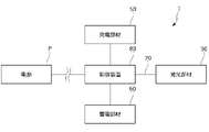
- the vehicle interior product is connected to the light emitting member, the power generation member, and the power storage member, respectively, and has a control controller for controlling the light emission of the light emitting member.
- the control controller is connected to a power source provided on the vehicle body to control the supply of electricity of the interior parts for the vehicle, and when the amount of power generated by the power generation member is less than a predetermined threshold, or the above.
- the amount of electricity stored by the electricity storage member is less than a predetermined threshold value, it is controlled to supply electricity from the power source to the light emitting member, and the amount of power generated by the power generation member is equal to or more than the predetermined threshold value.
- the power generation member or the electricity storage member When, or when the amount of electricity stored by the electricity storage member is equal to or greater than a predetermined threshold value, it is preferable to control the power generation member or the electricity storage member to supply electricity toward the light emitting member.
- electricity can be supplied from the power source on the vehicle body side to the light emitting member.
- electricity can be supplied from the power generation member or the electricity storage member to the power source or the electric component on the vehicle body side.
- the vehicle interior product is attached to the vehicle inner surface of the vehicle interior product and includes a decorative panel irradiated by the light emitting member, and the light emitting member is in the vertical direction or the vehicle front-rear direction. It is preferable that the decorative panel is arranged between the power generation member and the power storage member, and the decorative panel is arranged at a position facing the light emitting member. As described above, since the interior parts for vehicles are provided with decorative panels, it is possible to produce decorative lighting in the vehicle while supplying electricity by self-sufficiency.
- the present invention it is possible to realize an interior product for a vehicle capable of supplying electricity by itself and exhibiting a lighting function in the vehicle.
- the components for exhibiting the lighting function can be arranged compactly to suppress the increase in size.
- the power generation member can be suitably attached while following the outer surface of the vehicle interior product.
- the solar cell module can efficiently generate electricity.
- the weight of the vehicle door lining can be reduced.
- the solar cell module (solar cell) can efficiently generate electricity.
- the design of the surface of the solar cell module can be improved.
- scars and stains on the surface of the solar cell module can be made inconspicuous.
- This embodiment is a vehicle interior component (vehicle door lining) attached to a vehicle, and is electrically connected to a light emitting member that emits light toward the inside of the vehicle and is electrically connected to the light emitting member to supply electricity to the light emitting member. It includes a power generation member, a light emitting member, and a power storage member that is electrically connected to the power generation member and stores electricity.
- the power generation member is in the form of a sheet or a film and is arranged along the surface of the door lining.
- the present invention relates to an interior product for a vehicle, which is mainly characterized by the above.
- vehicle front-rear direction front-rear direction during normal driving of the vehicle
- vehicle inside in the vehicle width direction width direction
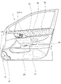
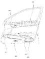
- the vehicle door lining 1 (hereinafter, also referred to as a door lining) of the first embodiment will be described with reference to FIGS. 1 to 8F.
- the vehicle door lining 1 is a vehicle interior component that decorates the inside of the vehicle door D, and is a group of parts attached to the door panel D1 that is the substrate of the vehicle door D. It is composed of.
- the door lining 1 is arranged above the armrest 2 that supports the arm of the seated person and the front portion of the armrest 2, and is an operation handle for opening and closing the vehicle door D. 3. It is provided with a pocket portion 4 arranged below the front portion of the armrest, and an operation panel 5 arranged on the upper surface of the armrest 2 for adjusting the opening and closing of the power window.
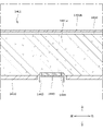
- the door panel D1 is mainly composed of an outer panel D2 and an inner panel D3 formed of a steel plate.
- a reinforcing member D4 extending in the front-rear direction of the seat is formed on the inner surface of the inner panel D3. Reinforcing members may be further formed on the inner surface of the outer panel D2 or the outer surface of the inner panel D3.
- the reinforcing member D4 has, for example, a vertical cross-sectional groove shape, and forms a closed cross-sectional structure together with the main body portion of the inner panel D3. Further, as shown in FIG. 3, the reinforcing member D4 extends from the front end portion of the door lining 1 toward the rear end portion while inclining downward.
- the door lining 1 is configured by coating a skin material 20 on a door lining base material 10 which is a substrate of the door lining 1.
- the door lining 1 has a front end portion of the door lining base material 10 rotatably attached to the vehicle body via a hinge 10a. Therefore, the connecting members of various electric parts provided on the door lining 1 extend toward the front end portion of the door lining 1.
- the connecting member is connected to a power source (power supply system) provided on the vehicle body.
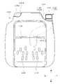
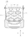
- the door lining 1 has a light emitting member 30 that emits light toward the inside of the vehicle, a decorative panel 40 that is irradiated by the light emitting member 30, and a power generation member 50 that supplies electricity to the light emitting member 30 in order to exert a lighting function in the vehicle.
- a lighting module includes a power storage member 60 for storing electricity, a light emitting member 30, a decorative panel 40, a power generation member 50, and a connection member 70 for electrically connecting each of the power storage member 60.
- the door lining 1 is provided with a control controller 80 that is electrically connected to the light emitting member 30, the decorative panel 40, the power generation member 50, and the power storage member 60 via the connecting member 70 to control the light emission of the light emitting member 30.
- the light emitting member 30, the decorative panel 40, the power generation member 50, the power storage member 60, and the control controller 80 are attached to each of the door lining base materials 10 at predetermined positions.
- the door lining base material 10 is a plate-shaped frame made of resin, and extends so as to be elongated in the front-rear direction of the vehicle.
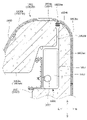
- the door lining base material 10 is formed on the inner side surface of the vehicle, and is formed at a position above the armrest base material portion 11 which is the base material portion of the armrest 2 and the armrest base material portion 11, and is formed as a light emitting member 30 and decoration.
- An assembly portion 12 for assembling the panel 40 and a shock absorbing portion 13 formed on the outer side surface of the door lining base material 10 and arranged below the armrest base material portion 11 and projecting toward the door panel D1. And have.
- the assembling portion 12 is formed as a substantially rectangular concave portion, a light emitting member 30 is attached to the bottom of the assembling portion 12, and a decorative panel 40 is fitted in the opening of the assembling portion 12. ..
- the surface of the door lining 1 and the decorative panel 40 are formed so as to be substantially flush with each other.
- the shock absorbing unit 13 is a shock absorbing body provided between the door panel D1 and the door lining 1 in order to alleviate the impact applied to the occupant from the vehicle door D at the time of a side collision of the vehicle.
- the shock absorbing portion 13 is formed as a substantially circular convex portion, and is formed so as to be gradually narrowed from the door lining 1 toward the door panel D1. In other words, it is formed so as to project in a staircase pattern.
- the skin material 20 is made of a resin material (for example, TPO), a cloth (for example, PET material), genuine leather, or the like, and may cover the inner surface of the door lining base material 10. It is formed in a possible shape.
- the skin material 20 includes a first skin material 21 that covers a portion above the armrest base material portion 11 on the inner surface of the door lining base material 10 and a portion below the armrest base material portion 11. It has a second skin material 22 to be covered.
- the skin terminal portions of the first skin material 21 and the second skin material 22 are attached to the skin attachment portions provided on the door lining base material 10.
- the door lining 1 does not have to have the skin material 20.
- the light emitting member 30 is a planar light emitting body elongated in the front-rear direction of the sheet, and specifically, a light source 31 such as an LED lamp and light emitted from the light source 31. It is mainly composed of a light guide body 32 that guides the light source 32 and a light emitting panel 33 that emits the guided light evenly over the entire surface.
- the light emitting member 30 may be a planar light emitting body such as an LED display or an organic EL display.
- the light emitting member 30 is arranged at a substantially central portion of the door lining 1. Specifically, it is arranged between the power generation member 50 and the power storage member 60 in the vertical direction. A decorative panel 40 is arranged at a position inside the vehicle facing the light emitting member 30.
- the decorative panel 40 is a planar resin member exposed inside the vehicle, has light transmission property, and exhibits the function of decorative lighting.
- the decorative panel 40 has a light emitting region 41 on the surface of the panel, and can display a predetermined decorative pattern by being irradiated by the light emitting member 30. More specifically, the light emitting region 41 is formed with a "touch panel” as an information display screen. Then, while the light emitting member 30 is irradiating with light, the "touch panel” is lit in the light emitting region 41 and information is displayed. On the other hand, the "touch panel” is turned off while the light emitting member 30 is not irradiating light, and the decorative panel 40 is configured to be in harmony with the surface of the door lining 1.
- At least one of the still image information, the moving image information, and the character information is displayed on the "touch panel".
- various information on the “touch panel” it is possible to improve the comfort in the interior of the vehicle.
- information on the current time, weather, room temperature, and humidity is displayed as the information displayed on the "touch panel”.
- an operation button for operating the reclining mechanism and the height link mechanism of the vehicle seat S is displayed.
- existing operation buttons such as windows, car audios, and car navigation systems can be replaced with "touch panels" for display.
- the seated person can operate the "touch panel” depending on the mood and situation, and the information displayed on the "touch panel” can be switched, so that the comfort in the vehicle is improved.
- the number of parts can be reduced and the space inside the vehicle can be secured.
- the design is improved more than before.
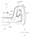
- the power generation member 50 is a film-shaped solar cell module, which is attached to the upper portion (upper end portion) of the door lining 1 and is attached along the inner surface of the door lining 1. Have been placed.
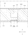
- the power generation member 50 is an organic thin-film type solar cell module, and as shown in FIG. 5, the solar cell 51, the sealing layer 52 for sealing the solar cell 51, and the sealing layer 52 are sealed. It is mainly composed of a power generator having a surface layer 53 provided on the surface side of the power generation member 50 with respect to the layer 52, and a resin film substrate 54 as a substrate of the power generation body.
- a plurality of power generators including the solar cell 51 are arranged (arranged so as to diffuse) on the film substrate 54 over substantially the entire area.
- the power generation member 50 may be a perovskite type solar cell module or the like, in addition to the organic thin film type. If it is a film-shaped solar cell module as described above, it can be shaped or bonded and attached according to the design shape of the door lining 1. Then, it is possible to realize a power generation member that is lighter and thinner than the conventional one.
- the solar cell 51 is an energy conversion element that absorbs light energy emitted from the sun and converts it into electricity, and is composed of a semiconductor such as silicon.
- the sealing layer 52 is formed by sealing the solar cell 51 with a resin adhesive.
- the surface layer 53 is formed by laminating a resin material having translucency (for example, ETFE (ethylene tetrafluoroethylene)). Therefore, the solar cell 51 can efficiently generate electricity. Further, a fine uneven shape is formed on the surface of the surface layer 53 by, for example, drawing. For example, a fine uneven shape having an arithmetic mean roughness Ra of 50 nm or more and 5 ⁇ m or less is formed. Therefore, the design of the surface of the power generation member 50 can be improved. In addition, scars and stains on the surface can be made inconspicuous.
- the power generation member 50 is arranged at the upper end portion of the door lining 1 and is attached while being curved along the surface of the skin material 20 of the door lining 1. Therefore, the film-shaped power generation member 50 can be suitably attached while following the surface of the door lining 1. Further, by attaching the power generation member 50 to a portion where sunlight is easily exposed, it is possible to efficiently generate power.
- a phosphorescent material may be laminated on the film substrate 54 at a position different from that of the solar cell 51 (power generator) to separately form a phosphorescent body that absorbs sunlight. Then, electricity can be suitably discharged from the power generation member 50. In addition, a new design can be added.
- the power storage member 60 is a plate-shaped storage battery that stores electricity generated by the power generation member 50 and supplies electricity to the light emitting member 30.
- the power storage member 60 is arranged below the light emitting member 30 and the power generation member 50, and is attached to the lower end portion of the armrest base material portion 11 in the door lining base material 10.
- the connecting member 70 is a film-shaped electric circuit (collecting sheet), and is formed by, for example, processing a conductive film substrate 70a and the surface of the film substrate 70a. It is mainly composed of the metal wiring 70b to be formed.
- the connection member 70 includes a first connection member 71 that connects the light emitting member 30, the power generation member 50, and the control controller 80, and a second connection member 72 that connects the light emitting member 30, the power storage member 60, and the control controller 80. ing.
- One end of the first connecting member 71 passes through a through hole 14 provided in the door lining base material 10 and is electrically connected to the lower end of the power generation member 50. Further, the other end of the first connecting member 71 is connected to the light emitting member 30 and the control controller 80 in a state of being sandwiched between the light emitting member 30 and the control controller 80. One end of the second connecting member 72 is sandwiched and connected between the light emitting member 30 and the control controller 80. Further, the other end of the second connecting member 72 is connected to the upper end of the power storage member 60.
- the connecting member 70 is composed of a film-shaped electric circuit, it can be arranged more compactly when compared with a conventional harness. Further, the weight of the door lining 1 can be reduced.
- the light emitting member 30 and the power storage member 60 are arranged above the reinforcing member D4 and the shock absorbing portion 13 in the side view of the door lining 1, and the reinforcing member D4 and the storage member 60 are arranged. It is arranged at a position avoiding the shock absorbing portion 13. Therefore, the work of attaching and detaching the light emitting member 30 and the power storage member 60 becomes easy.
- the light emitting member 30 and the power storage member 60 are arranged at overlapping positions in the vehicle front-rear direction and the thickness direction of the door lining 1, and are arranged at positions close to each other. Has been done. Further, the light emitting member 30 and the power storage member 60 are arranged at positions outside the vehicle with respect to the decorative panel 40. Therefore, the light emitting member 30 and the power storage member 60 can be arranged compactly, and electricity can be efficiently supplied from the power storage member 60 toward the light emitting member 30.
- the decorative panel 40 is arranged inside the vehicle with respect to the light emitting member 30, the power generation member 50, and the power storage member 60. Therefore, the design of the decorative panel 40 can be improved.
- the control controller 80 is a control device that comprehensively controls the lighting function of the door lining 1, and is attached to the back surface of the light emitting member 30.
- the control controller 80 is connected to the light emitting member 30 (decorative panel 40), the power generation member 50, and the power storage member 60, and the power generation member is based on the input of a predetermined user operation by the seated person.
- the electricity supply from the 50 or the power storage member 60 to the light emitting member 30 and the decorative panel 40 is controlled.
- a predetermined decoration pattern can be displayed in the light emitting area 41 of the decoration panel 40.
- a "touch panel" as an information display screen can be displayed in the light emitting area 41.
- the control controller 80 is electrically connected to a power source P (for example, an in-vehicle battery) provided on the vehicle body via a connection member (not shown), and is connected to the power supply P.
- the door lining 1 is electrically controlled while the electric supply is delivered.
- the control controller 80 receives power from the power source P when the amount of power generated by the power generation member 50 is less than a predetermined threshold value or when the amount of electricity stored by the power storage member 60 is less than a predetermined threshold value. Controls to supply electricity to electrical components. That is, when the amount of electricity generated by the power generation member 50 and the power storage member 60 is insufficient, power is supplied from the power source P on the vehicle body side.
- control controller 80 is the power generation member 50 or the power storage member when the power generation amount generated by the power generation member 50 is equal to or more than a predetermined threshold value or when the storage amount stored by the power storage member 60 is equal to or more than a predetermined threshold value. It is controlled to supply electricity from 60 toward the power source P and electric parts. That is, when the amount of electricity generated by the power generation member 50 and the power storage member 60 is sufficient, electricity is supplied to the power source P and the electric components on the vehicle body side.
- each component for exhibiting the lighting function can be arranged compactly, and the weight can be reduced as compared with the conventional case.
- the power generation member 50 can efficiently generate power.
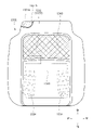
- the door lining 101 of the second embodiment will be described with reference to FIG. 7.
- the description of the contents overlapping with the above-mentioned door lining 1 will be omitted.
- the door lining 101 is different from the door lining 1 in that the components for exhibiting the lighting function are mainly different from each other.
- the door lining 101 includes a light emitting member 130 having a light emitting region 132, a power generation member 150, a power storage member 160, a connection member 170, and a control controller 180 as lighting modules in order to exert a lighting function in the vehicle. There is.
- the light emitting member 130, the power generation member 150, the power storage member 160, and the connecting member 170 are integrally formed in a film shape and integrally attached to the surface of the skin material 120 of the door lining 101.
- the light emitting member 130 is a film-shaped light emitting body, and is formed by printing an inorganic compound (for example, zinc sulfide) on a conductive film substrate 131 (for example, PET film substrate). The surface of the light emitting member 130 is formed as a light emitting region 132.
- the power generation member 150 is a film-shaped solar cell module, and is formed by laminating a laminate including a solar cell on the film substrate 131.
- the power storage member 160 is a film-shaped storage battery (for example, a film-type lithium ion secondary battery), and is formed by applying a gel-like or jelly-like electrolyte material on the film substrate 131.
- the connection member 170 is a film-shaped electric circuit, and the electric circuit is formed by providing metal wiring on the film substrate 131.
- the connecting member 170 has a first connecting member 171 that connects the light emitting member 130, the power generation member 150, and the control controller 180, and a second connecting member 172 that connects the light emitting member 130 and the power storage member 160.
- the control controller 180 is a microcontroller, which is arranged between the light emitting member 130 and the power generation member 150, and is attached to the back surface of the film substrate 131.
- each component for exhibiting the lighting function can be arranged more compactly, and the weight can be further reduced as compared with the conventional case.
- the module product can be easily attached to the vehicle door lining.
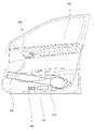
- the door lining 201 of the third embodiment includes a light emitting member 230, a power generation member 250, and a power storage member 260 as a lighting module.
- the light emitting member 230 and the power storage member 260 are arranged so as to be arranged in the front-rear direction of the vehicle (on the same horizontal plane) in order to be arranged compactly.
- the light emitting member 230 and the power storage member 260 are arranged below the reinforcing member D4 in the side view of the door lining 201, and are arranged at positions avoiding the reinforcing member D4.
- the light emitting member 230 and the power storage member 260 are arranged at a position in front of the shock absorbing unit 213 and at a position avoiding the shock absorbing unit 213. Therefore, the work of attaching and detaching the light emitting member 230 and the power storage member 260 becomes easy.
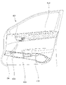
- the door lining 301 of the fourth embodiment includes a light emitting member 330, a power generation member 350, and a power storage member 360 as a lighting module.
- the light emitting member 330 and the power storage member 360 are arranged so as to be arranged in the front-rear direction of the vehicle (on the same horizontal plane) in order to be arranged compactly.
- the light emitting member 330 and the power storage member 360 are arranged at positions overlapping with the armrest 302 in the side view of the door lining 301. Further, the light emitting member 330 and the power storage member 360 are arranged at positions above the reinforcing member D4, and are arranged at positions avoiding the reinforcing member D4.
- the light emitting member 330 and the power storage member 360 are arranged at a position in front of the shock absorbing unit 313 and at a position avoiding the shock absorbing unit 313. Therefore, the work of attaching and detaching the light emitting member 330 and the power storage member 360 becomes easy.
- the door lining 401 of the fifth embodiment includes a light emitting member 430, a power generation member 450, and a power storage member 460 as lighting modules.
- the light emitting member 430 and the power storage member 460 are arranged at positions where at least a part of the reinforcing member D4 overlaps with the reinforcing member D4 in the side view of the door lining 401. Therefore, the light emitting member 430 and the power storage member 460 are protected by the reinforcing member D4.
- the entire light emitting member 430 and the power storage member 460 may be arranged at a position where they overlap with the reinforcing member D4.
- the light emitting member 430 and the power storage member 460 are arranged at a position in front of the shock absorbing unit 413 and at a position avoiding the shock absorbing unit 413. Therefore, the work of attaching and detaching the light emitting member 430 and the power storage member 460 becomes easy.
- the door lining 501 of the sixth embodiment includes a light emitting member 530, a power generation member 550, and a power storage member 560 as lighting modules.
- the light emitting member 530 is arranged above the reinforcing member D4 and the shock absorbing portion 513 in the side view of the door lining 501, and is arranged at a position avoiding the reinforcing member D4 and the shock absorbing portion 513. Therefore, the work of attaching and detaching the light emitting member 530 becomes easy.
- the power storage member 560 is arranged at a position where it overlaps with the reinforcing member D4, and is arranged at a position where it overlaps with the shock absorbing portion 513. Therefore, the power storage member 560 is protected by the reinforcing member D4.
- the power storage member 560 may be arranged at a position where it partially overlaps with the reinforcing member D4 and the impact absorbing unit 513.
- the door lining 601 of the seventh embodiment includes a light emitting member 630, a power generation member 650, and a power storage member 660 as lighting modules.
- the light emitting member 630 is arranged at a position overlapping with the reinforcing member D4 in the side view of the door lining 601 and is arranged at a position overlapping with the shock absorbing portion 613. Therefore, the light emitting member 630 is protected by the reinforcing member D4 and the impact absorbing portion 613.
- the light emitting member 630 may be arranged at a position where it partially overlaps with the reinforcing member D4 and the impact absorbing portion 613.
- the power storage member 660 is arranged at a position below the reinforcing member D4 and is arranged at a position in front of the shock absorbing portion 613. Therefore, the work of attaching and detaching the light emitting member 630 becomes easy.
- the door lining 701 of the eighth embodiment includes a light emitting member 730, a power generation member 750, and a power storage member 760 as lighting modules.
- the light emitting member 730 and the power storage member 760 are arranged above the reinforcing member D4 and the shock absorbing portion 713 in the side view of the door lining 701.
- the light emitting member 730 is arranged between the power generation member 750 and the power storage member 760 in the front-rear direction of the vehicle.
- the light emitting member 730 is provided at a position adjacent to the operation handle 703, and is arranged at a position overlapping the storage recess in which the operation handle 703 is housed. Therefore, the empty space around the operation handle 703 can be suitably illuminated.
- each component for exhibiting the lighting function can be arranged more compactly.
- the module product can be easily attached to the vehicle door lining.
- the light emitting member 730, the power generation member 750, and the power storage member 760 are arranged, even if an impact load is applied to the vehicle door D at the time of a side collision of the vehicle, the light emitting member 730, the power generation member 750, and the power storage member are arranged.
- the effect on 760 can be mitigated. More specifically, when an impact load is applied to the vehicle door D at the time of a side collision of the vehicle, the portion provided with the reinforcing member D4 and the impact absorbing portion 713 is most affected. At this time, since the light emitting member 730, the power generation member 750, and the power storage member 760 are arranged at positions avoiding the reinforcing member D4 and the impact absorbing portion 713, the influence of the impact load can be suppressed.
- the arrangement is close to the front end portion of the vehicle door D, and the arrangement is close to the power supply (power supply system) provided on the vehicle body.
- the lighting module can efficiently receive electricity from the vehicle body power supply, and the loss of electricity can be suppressed as much as possible.
- the vehicle door lining 1 includes a light emitting member 30, a power generation member 50, and a power storage member 60 in order to exert a lighting function in the vehicle, but is particularly limited. It may be applied to vehicle interior parts other than vehicle door linings without being used.
- vehicle interior parts such as an instrument panel, a console box, and a rear tray may include a light emitting member 30, a power generation member 50, and a power storage member 60.
- the power generation member 50 and the connecting member 70 are formed of a sheet-shaped or film-shaped member, but can be changed without particular limitation.
- the power generation member 50 may be a plate-shaped or panel-shaped solar cell.
- the connecting member 70 may be a conventional electric wiring or a harness in which a plurality of electric wirings are bundled.
- the power generation member 50 and the connection member 70 are made of a flexible material in the form of a sheet or a film.
- the light emitting member 30 and the power storage member 60 are also preferably formed of a sheet-like or film-like flexible material. More preferably, the light emitting member 30 has a light emitting region, and the decorative panel 40 may be made unnecessary by also having the function of the decorative panel 40.
- the vehicle seat S1 realizes a seat capable of efficiently receiving the load applied from the occupant to the seat back at the time of a rear collision of the vehicle. More specifically, the vehicle seat S1 is provided with a seat back configured by adhering a skin material to a pad material, and is capable of efficiently receiving a load applied from an occupant to the seat back in the event of a rear collision of the vehicle. It will be realized.
- the vehicle seat S1 is attached to the inside of the seat body having the seat cushion 1001 and the seat back 1002, and the seat back 1002, and the central portion 1002A of the seat back 1002 is normally positioned.
- a lumbar support 1030 that is movable to project toward the seated person
- a movable body 1040 that is attached to the inside of the seat body and is movable to project the side portion 1002B of the seat back 1002 toward the seated person from the normal position.
- (Side support member) and an actuating device 1050 (fluid supply device) that operates to move the lumbar support 1030 and the movable body 1040 are provided.
- the seat cushion 1001 is a seating portion that supports the seated person from below, and the pad material 1001a is placed on the cushion frame 1010 shown in FIG. 10 as a skeleton and covered with the skin material 1001b. It is composed of.
- the seat back 1002 is a backrest portion that supports the back of the seated person from behind, and the pad material 1002a is placed on the back frame 1020 shown in FIG. 10 as a skeleton, and the skin material 1002b is used. It is covered and configured.
- the seat back 1002 is composed of a central portion 1002A in the central portion in the seat width direction and left and right side portions 1002B (side bolster portions) outside the central portion 1002A in the seat width direction.
- left and right hanging grooves 1002C extending in the vertical direction are formed so as to separate the central portion 1002A and the left and right side portions 1002B.
- the cushion frame 1010 is composed of a rectangular frame-shaped body, and has a side frame 1011 arranged on the left and right sides and a plate-shaped pan frame 1012 erected on the front end portion of each side frame 1011.
- a plurality of support members 1014 that are hooked to the (erection frame), the rear connecting frame 1013 that connects the rear portions of the side frames 1011 to the pan frame 1012 and the rear connecting frame 1013, and extend in the front-rear direction of the seat.
- it is mainly composed of.
- the side frame 1011 is a plate-shaped frame that is long in the front-rear direction of the seat.
- a reclining device 1004 is attached to the rear portion of the side frame 1011 and a rail device 1006 is attached to the lower portion thereof via the height link device 1005.
- the back frame 1020 has a rectangular frame-like body, and has an inverted U-shape that connects the back side frames 1021 arranged on the left and right sides and the upper end portions of the back side frames 1021.
- a plurality of wire members 1024 that are hooked to the upper frame 1022, the plate-shaped lower frame 1023 that connects the lower end portions of the backside frames 1021, and each backside frame 1021, and extend in a serpentine manner in the seat width direction. It is mainly composed of a (elastic wire) and a support plate 1025 that is held by a plurality of wire members 1024 and supports a seated person.
- the backside frame 1021 is a sheet metal member extending in the vertical direction and having a substantially C-shaped cross section, and its lower end portion is connected to the rear end portion of the side frame 1011 via a reclining device 1004. In the above configuration, the back frame 1020 can rotate relative to the cushion frame 1010.
- a lumbar support 1030 is attached to the front surface of the lower portion of the support plate 1025. Further, as shown in FIG. 10, left and right movable bodies 1040 are attached to the front surface of the lower portion of the left and right backside frames 1021.
- the lumbar support 1030 has a bag body (air cell) that swells when a fluid is sealed, and the seated side is filled with compressed air as a fluid. It swells to (protrudes from the normal position to the protruding position) and contracts (returns to the normal position) when the enclosed compressed air is discharged.
- the lumbar support 1030 is a member that supports the waist of the seated person, and is arranged between the pad material 1002a and the support plate 1025 in the central portion 1002A of the lower portion of the seat back 1002. Then, it is a member that is movable in order to project the central portion 1002A (pad material 1002a) toward the seated person.
- the lumbar support 1030 is attached to the front surface of the support plate 1025 in a folded state.
- the lumbar support 1030 has a long rectangular shape in the seat width direction, and is formed from a base member 1031 (base plate) supported by the support plate 1025 and a bag body 1032 supported by the front surface of the base member 1031. It is mainly composed.
- the bag body 1032 can bulge toward the front side of the seat by being filled with compressed air from the folded state.
- the movable body 1040 has a bag body (air cell), and is bulged toward the seated person (protruding from the normal position to the protruding position) by being filled with compressed air. It contracts (returns to the normal position) when the enclosed compressed air is discharged.
- the movable body 1040 is a side support member that supports the seated person from the side, and is arranged between the pad material 1002a and the back side frame 1021 in the side portion 1002B of the lower portion of the seat back 1002. ..
- the movable body 1040 is attached to the front surface of the backside frame 1021 in a folded state.
- the movable body 1040 has a substantially pentagonal shape that is long in the vertical direction, and is arranged at a position in front of the base member 1041 supported by the backside frame 1021 and the base member 1041 with respect to the base member 1041.
- a rotating member 1043 attached so as to be rotatable via a rotating shaft 1042, and a bag body 1044 arranged between the base member 1041 and the rotating member 1043 and supported on the front surface of the base member 1041. It is mainly composed of.
- the base member 1041 is attached to the front surface of the backside frame 1021 and extends along the front surface of the backside frame so as to project in the seat width direction.
- the rotation shaft 1042 is attached to the inner end portion in the seat width direction of the front surface of the base member 1041.
- the rotating member 1043 is rotatably attached to the base member 1041 in the front-rear direction of the seat, and by rotating toward the front of the seat, the side portion 1002B of the seat back 1002 is projected toward the front of the seat ( Can be extruded).
- the rotating member 1043 is arranged at a position closer to the base member 1041 when the seat back 1002 is in the normal position. It may be in a state of being urged to the base member 1041 side by an urging spring (urging member) (not shown).
- the bag body 1044 is supported by the base member 1041 and can be expanded toward the front side of the seat by being filled with compressed air, and the rotating member 1043 can be pushed out toward the front side of the seat. That is, the rotating member 1043 can be rotated forward of the seat.
- the protrusion direction and the protrusion amount of the seat back 1002 can be adjusted by inflating the bag body 1044.
- the actuating device 1050 is attached to the inside of the seat body and is a fluid for supplying compressed air to the lumbar support 1030 (bag body 1032) and the movable body 1040 (bag body 1044). It is a supply device.
- the actuating device 1050 is attached to the back surface of the air control unit 1051 attached to the outer surface of the backside frame 1021 and the back surface of the cushion frame 1010 (pan frame 1012) to supply (supply) and discharge (exhaust) compressed air. It is mainly composed of an air pump 1052 for the purpose and an air pipe 1053 connecting the air pump 1052 and the lumbar support 1030 (movable body 1040).
- the air control unit 1051 receives, for example, a predetermined user operation selection by a seated person and receives a predetermined control signal to supply compressed air to the bag bodies 1032 and 1044, or compressed air from the bag bodies 1032 and 1044.
- the air pump 1052 is controlled to discharge the air. By doing so, the movable range of the lumbar support 1030 and the movable body 1040 can be adjusted according to the physique of the seated person.
- the rear end portion of the movable body 1040 is the central portion 1002A of the seat back 1002. It is located on the front side of the seat from the seating surface of.
- a plurality of bag bodies 1044 are arranged on the front side of the seat with respect to the seating surface of the central portion 1002A of the seat back 1002. Therefore, it is possible to prevent wrinkles and duplication from occurring in the skin material 1002b of the seat back 1002.
- the movable body 1040 can be moved to move the side portion 1002B of the seat back 1002 from the "normal position" shown in FIG. 12A to the "protruding position” shown in FIG. 12B.
- FIG. 12A is a diagram showing a state in which the side portion 1002B of the seat back 1002 is in the “normal position”.
- FIG. 12B is a diagram showing a state in which the movable body 1040 protrudes forward of the seat and the side portion 1002B moves from the “normal position” to the “protruding position”. Specifically, by receiving the supply of compressed air from the actuating device 1050, the folded bag body 1044 expands and expands toward the front of the seat, and the rotating member 1043 is pushed toward the front of the seat to push the side. The portion 1002B moves to the front of the seat. As a result, the side portion 1002B moves to the "protruding position”.
- the compressed air inside the bag body 1044 is discharged by the actuating device 1050, so that the bag body 1044 in the inflated state contracts and the side portion 1002B is lowered to the rear of the seat. As a result, the side portion 1002B returns from the "protruding position" to the "normal position".
- the pad material 1002a and the skin material 1002b are adhered by the adhesive portion 1060.
- the adhesive portion 1060 is a portion provided with an adhesive, and is applied to the surface of the pad material 1002a continuously or at predetermined intervals along the vertical direction and the sheet width direction.
- the adhesive portion 1060 has a central adhesive portion 1061 arranged in the central portion 1002A of the seat back 1002, and a first side adhesive portion 1062 and a second side adhesive portion 1063 arranged in the side portion 1002B.
- the central adhesive portion 1061 is arranged at a position overlapping with the lumbar support 1030 in the sheet width direction and the vertical direction. Further, the central adhesive portion 1061 is arranged inside the left and right suspension grooves 1002C in the sheet width direction. More specifically, the central adhesive portion 1061 is arranged inside the left and right surface fragile portions 1070 formed on the surface of the pad material 1002a in the sheet width direction, and the left and right formed on the back surface of the pad material 1002a. It is arranged inside the fragile portion 1080 on the back surface of.
- the first side adhesive portion 1062 is arranged at a position overlapping with the movable body 1040 in the sheet width direction and the vertical direction.
- a plurality of first side adhesive portions 1062 are arranged at predetermined intervals in the sheet width direction and the vertical direction.
- the first side adhesive portion 1062 is arranged so as to avoid a portion of the side portion 1002B that is easily deformed by the movable body 1040 (specifically, the portion that is most easily deformed).
- the most easily deformable portion of the side portion 1002B corresponds to the front end portion of the side portion 1002B.
- the second side adhesive portion 1063 is arranged at a position overlapping with the movable body 1040 in the front-rear direction and the vertical direction of the seat.
- the second side adhesive portion 1063 is continuously arranged in the front-rear direction and the vertical direction of the sheet.
- the surface fragile portion 1070 is a groove formed on the surface of the pad material 1002a at a position inside the suspension groove 1002C and adjacent to the suspension groove 1002C.
- the back surface fragile portion 1080 is a groove formed in the back surface of the pad material 1002a at a position inside the suspension groove 1002C and adjacent to the suspension groove 1002C.
- the back surface fragile portion 1080 is arranged between the front surface fragile portion 1070 and the suspension groove 1002C in the sheet width direction.
- the front surface fragile portion 1070 and the back surface fragile portion 1080 are grooves (recesses) continuously formed along the vertical direction, but are not particularly limited and are formed at predetermined intervals along the vertical direction. It may be a groove (through groove).
- the adhesive portion 1060 is provided in the seat back 1002, the pad material 1002a and the skin material 1002b can be suitably adhered to each other. Further, since the "non-adhesive region" is formed in the seat back 1002 and the front surface fragile portion 1070 and the back surface fragile portion 1080 are formed, the load applied from the occupant to the seat back 1002 at the time of the rear surface collision of the vehicle can be efficiently received. It is possible to realize a vehicle seat that can be used. Specifically, the support plate 1025 can efficiently receive the load applied from the occupant to the seat back 1002 at the time of a rear surface collision.
- the vehicle seat S2 of the second embodiment will be described with reference to FIGS. 13 to 14A and B.
- the description of the contents overlapping with the vehicle seat S1 described above will be omitted.
- the vehicle seat S2 is provided with a blower device inside the seat body, and realizes a seat capable of appropriately securing a space for arranging a duct of the blower device. Further, the vehicle seat S2 realizes a seat capable of suppressing unintentional contact between the skin material and the duct in the seat body.
- the vehicle seat S2 includes a seat cushion 1101, a seat back 1102, and a blower device 1130 attached to the inside of the seat cushion 1101.
- the pad material 1101a and the skin material 1101b are adhered by the adhesive portion 1160.
- the blower device 1130 is attached to the bottom surface of the seat cushion 1101 (pad material 1101a).
- the blower device 1130 is configured to blow air from the blower main body 1131 toward the occupant (seat) through the duct 1132, the ventilation passage 1133 formed in the pad material 1101a, and the ventilation hole 1134.
- the duct 1132 is arranged at the rear end portion of the seat cushion 1101 (pad material 1101a) at the left side position, and extends along the vertical direction. More specifically, the duct 1132 is arranged at a position avoiding the pad material 1101a, and extends in the vertical direction so as to face the outer edge portion of the pad material 1101a. In other words, in the portion of the pad material 1101a corresponding to the duct 1132, a notch portion 1170 (duct relief portion) for not interfering with the duct 1132 is formed.
- the adhesive portion 1160 is a portion provided with an adhesive, and is applied to the surface of the pad material 1101a continuously or at intervals along the front-rear direction of the sheet and the width direction of the sheet.
- the adhesive portion 1160 has an upper surface adhesive portion 1161 applied to the upper surface of the pad material 1101a and a side adhesive portion 1162 applied to the outer surface of the pad material 1101a.
- the side adhesive portion 1162 is formed in the portion adjacent to (close to) the duct 1132 in the outer edge portion of the pad material 1101a.
- the pad material 1101a and the skin material 1101b can be suitably brought into close contact with each other around the duct 1132, and it is possible to prevent the skin material 1101b and the duct 1132 from coming into contact with each other unintentionally. That is, the skin material 1101b does not unintentionally shake and move at the peripheral position of the duct 1132 (for example, the position above the duct 1132), and the generation of abnormal noise due to the contact between the skin material 1101b and the duct 1132 is suppressed. can. It is also possible to secure the passage area of the duct 1132 and increase the passage area.
- a curved notch portion 1170 may be formed on the outer edge portion of the pad material 1101a. Then, it is preferable that the side bonding portion 1162 is provided in the notch portion 1170. By doing so, it is possible to further prevent the skin material 1101b and the duct 1132 from coming into contact with each other unintentionally.
- the vehicle seat S3 of the third embodiment will be described with reference to FIGS. 15 to 17D.
- the description of the contents overlapping with the above-mentioned vehicle seats S1 to S2 will be omitted.
- the vehicle seat S3 is provided with a blower device inside the seat body, and realizes a seat capable of ensuring the air conditioning capacity of the blower device regardless of the means for attaching the skin material.
- the vehicle seat S3 is provided with a detection sensor (seating sensor) inside the seat body, and realizes a seat capable of improving the detection accuracy by the detection sensor regardless of the means for attaching the skin material. be.
- the vehicle seat S3 includes a seat cushion 1201, a seat back 1202, a blower device 1230 mounted inside the seat cushion 1201, and a detection sensor 1240 mounted inside the seat cushion 1201. And have.
- the pad material 1201a and the skin material 1201b are adhered by the adhesive portion 1260.
- the detection sensor 1240 is a planar pressure sensor that detects the seating pressure of a seated person, and is also referred to as a seating sensor. As shown in FIG. 16, the detection sensor 1240 is attached to the central portion of the cushion frame 1210 in the front-rear direction and the width direction of the seat. As shown in FIG. 17A, the detection sensor 1240 has a detection unit 1241 for detecting the seating pressure of a seated person and a transmission line 1242 for transmitting the detection data obtained by the detection unit 1241 toward a control device (not shown). And have. The detection unit 1241 is in contact with the bottom surface of the pad material 1201a.
- the detection sensor 1240 (detection unit 1241) is mounted on the cushion frame 1210 via the mounting bracket 1243. Further, the detection sensor 1240 is housed in a sensor storage recess 1244 formed on the bottom surface of the pad material 1201a.
- the detection sensor 1240 is arranged at a position different from the adhesive portion 1260 for adhering the pad material 1201a and the skin material 1201b in the sheet front-rear direction and the sheet width direction.
- the detection sensor 1240 is arranged at a position not facing the "adhesive region" where the adhesive portion 1260 is formed.
- the blower device 1230 is attached to the bottom surface of the cushion frame 1210 as shown in FIGS. 16, 17A and 17B.
- the blower device 1230 is configured to blow air toward the occupant through a duct 1232, a vent passage 1233, and a plurality of vents 1234.
- the duct 1232 is attached to the cushion frame 1210 via the mounting bracket 1235 and extends in the vertical direction.
- the ventilation passage 1233 is connected to the duct 1232 and is branched into a plurality of portions so as to extend in the front-rear direction of the seat and the width direction of the seat.
- the plurality of ventilation holes 1234 are connected to the ventilation passage 1233 and extend in the vertical direction.
- the ventilation passage 1233 is arranged at a position not facing the "adhesive region" in which the adhesive portion 1260 is formed. Further, as shown in FIG. 17B, the ventilation path 1233 is arranged at a position not facing the "adhesive region”.
- the duct 1232 and the ventilation passage 1233 are arranged at positions facing the "partially bonded region" formed by the bonding portions 1260 at intervals. That is, the duct 1232, the ventilation passage 1233, and the ventilation hole 1234 are arranged at positions avoiding the "completely bonded region" in which the bonded portion 1260 is continuously formed.
- the "partially bonded region" formed by the bonded portions 1260 at intervals is a high hardness region in which the pad material 1201a has a relatively high hardness. Therefore, it is possible to prevent the air-conditioned passage from being affected by the seating load of the occupant.
- the detection sensor 1240, the duct 1232, the ventilation passage 1233, and the ventilation hole 1234 may be arranged respectively.
- the detection sensor 1240 is arranged at a position facing the "adhesive region" where the adhesive portion 1260 is formed.
- the peripheral position of the detection sensor 1240 is arranged so as to face the "non-adhesive region" in which the adhesive portion 1260 is not formed.
- the peripheral position of the detection sensor 1240 may face the "partially bonded region”. By doing so, it is possible to ensure the detection accuracy by the detection sensor 1240.
- the ventilation path 1233 has a "completely bonded region” in which the bonded portions 1260 are continuously formed, or a “partially bonded region” in which the bonded portions 1260 are formed at intervals. It is located at the opposite position. Further, as shown in FIG. 17D, the duct 1232 is arranged at a position facing the "partially bonded region".
- the "completely bonded region” and “partially bonded region” are high hardness regions in which the pad material 1201a has a relatively high hardness. By doing so, it is possible to prevent the air-conditioning passage from being affected by the seating load of the occupant and the like, and it is possible to suppress a decrease in the air-conditioning capacity.
- the vehicle seat S4 of the fourth embodiment will be described with reference to FIGS. 18 to 20.
- the description of the contents overlapping with the above-mentioned vehicle seats S1 to S3 will be omitted.
- the vehicle seat S4 is provided with a blower device inside the seat body, and realizes a seat capable of ensuring the air conditioning capacity of the blower device regardless of the means for attaching the skin material.
- the vehicle seat S4 includes a seat cushion 1301, a seat back 1302, and a blower device 1330 attached to the inside of the seat cushion 1301.
- the pad material 1301a and the skin material 1301b are adhered by the adhesive portion 1360.
- the blower device 1330 is attached to the bottom surface of the cushion frame 1310 as shown in FIGS. 18 to 20.
- the blower device 1330 is configured to blow air toward the occupant through the duct 1332, the ventilation passage 1333, and the plurality of ventilation holes 1334.
- the plurality of ventilation holes 1334 are arranged so as to be arranged in the front-rear direction of the seat, and are arranged at intervals in the width direction of the seat.
- the front portion of the seat cushion 1301 in which the plurality of ventilation holes 1334 are formed is the "ventilation region”. Further, the rear portion of the seat cushion 1301 in which the ventilation holes 1334 are not formed is a “non-ventilated region”.
- the "ventilation region” in which the plurality of ventilation holes 1334 are formed in the seat cushion 1301 corresponds to the "non-adhesive region" in which the adhesive portion 1360 is not provided. It is configured in. Further, the “non-ventilated region” in which the ventilation holes 1334 are not formed in the seat cushion 1301 is configured to correspond to the "adhesive region” in which the adhesive portion 1360 is provided. Further, the area of the "ventilated region (non-adhesive region)" is larger than the area of the "non-ventilated region (adhesive region)".
- the air conditioning capacity of the blower device 1330 can be ensured regardless of the mounting means of the skin material 1301b (not affected by the adhesion). Further, the skin material 1301b can be suitably adhered and fixed to the pad material 1301a.
- the plurality of ventilation holes 1334 are arranged so as to be arranged in the front-rear direction of the seat, and are arranged at intervals in the width direction of the seat.
- the "adhesive region" formed by the adhesive portion 1360 also extends along the front-rear direction of the sheet and the width direction of the sheet.
- the "ventilation region" in which the plurality of ventilation holes 1334 are formed in the seat cushion 1301 corresponds to the "non-adhesive region", but the adhesive portions 1360 are formed at intervals. It may correspond to the "partially bonded area”. By doing so, the air conditioning capacity of the blower device 1330 can be ensured.
- the vehicle seat S5 of the fifth embodiment will be described with reference to FIGS. 21 to 22.
- the description of the contents overlapping with the above-mentioned vehicle seats S1 to S4 will be omitted.
- the vehicle seat S5 is provided with a detection sensor (seating sensor) inside the seat body, and realizes a seat capable of ensuring detection accuracy by the detection sensor regardless of the means for attaching the skin material. ..
- the vehicle seat S5 includes a seat cushion 1401, a seat back 1402, and a detection sensor 1440 mounted inside the seat cushion 1401.
- the pad material 1401a and the skin material 1401b are adhered by the adhesive portion 1460.
- the detection sensor 1440 is a planar pressure sensor that detects the seating pressure of the seated person.
- the detection sensor 1440 is mounted on a mounting bracket 1443 fixed on the vehicle body floor.
- the detection sensor 1440 is arranged so as to abut on the bottom surface of the pad material 1201a through the opening of the cushion frame 1410. More specifically, the detection sensor 1440 is housed in a sensor storage recess 1444 formed on the bottom surface of the pad material 1401a.
- the detection sensor 1440 By arranging the detection sensor 1440 on the bottom surface of the pad material 1401a as described above, the detection sensor 1440 can be arranged regardless of the mounting means of the skin material 1401b (not affected by adhesion). Further, the "adhesive region" in which the adhesive portion 1460 is formed is a high hardness region in which the pad material 1401a has a relatively high hardness. Therefore, the seating load by the occupant can be suitably transmitted to the detection sensor 1440, and the detection accuracy by the detection sensor 1440 can be ensured.
- the mounting bracket 1443 is fixed on the vehicle body floor, but is not particularly limited, and may be fixed to the cushion frame 1410 or the pad material 1401a.
- the mounting bracket 1443 is fixed to the pad material 1401a, it is preferable that the mounting bracket 1443 is fixed to the pad material 1401a with an adhesive.
- the mounting bracket 1443 may be integrated with the pad material 1401a by integral foam molding.
- the vehicle seat S6 of the sixth embodiment will be described with reference to FIGS. 23 to 25.
- the description of the contents overlapping with the above-mentioned vehicle seats S1 to S5 will be omitted.
- the vehicle seat S6 is provided with a seat heater inside the seat body, and even when the pad material and the skin material are fixed with an adhesive, the seat heater mounting state (adhesive state) is not affected. It is intended to realize a seat devised in this way.
- the vehicle seat S6 includes a seat cushion 1501, a seat back 1502, and a seat heater 1550 mounted inside the seat cushion 1501.
- the pad material 1501a and the skin material 1501b are adhered by the adhesive portion 1560.
- the seat heater 1550 is a planar heating element that warms the seat cushion 1501, and is attached to the surface of the pad material 1501a by an adhesive portion 1570.
- the "first adhesive region" to which the pad material 1501a and the skin material 1501b are adhered by the adhesive portion 1560 is a region wider in the sheet width direction than in the front-rear direction of the sheet. ..
- the "second adhesive region" to which the pad material 1501a and the sheet heater 1550 are adhered by the adhesive portion 1570 is a region wider in the front-rear direction of the sheet than in the width direction of the sheet.
- first adhesive region and the “second adhesive region” are arranged so as to partially overlap each other in the central portion of the seat cushion 1501.
- first adhesive region and the “second adhesive region” may be arranged so as not to overlap. That is, the "first adhesive region” formed by the adhesive portion 1560 may be formed while avoiding the “second adhesive region” formed by the adhesive portion 1570.
- the adhesive portion 1560 and the adhesive portion 1570 have different melting points due to the adhesive. More specifically, the melting point of the bonded portion 1560 is lower than the melting point of the bonded portion 1570.
- the adhesive state of the adhesive portion 1570 may be affected. not. That is, when the pad material 1501a and the skin material 1501b are adhered by the adhesive portion 1560, they are heated and melted at a temperature higher than the melting point of the adhesive portion 1560 and lower than the melting point of the adhesive portion 1570. It is possible to prevent the adhesive portion 1570 from being affected.
- the vehicle seat S7 of the seventh embodiment will be described with reference to FIGS. 26 to 27.
- the description of the contents overlapping with the above-mentioned vehicle seats S1 to S6 will be omitted.
- the vehicle seat S7 is provided with a seat heater inside the seat body, and realizes a seat in which the seat heater and the skin material can be efficiently attached to the pad material.
- the vehicle seat S7 includes a seat cushion 1601, a seat back 1602, and a seat heater 1650 mounted inside the seat cushion 1601.
- the pad material 1601a and the skin material 1601b are adhered by the adhesive portion 1660.
- the seat heater 1650 is a planar heating element that warms the seat cushion 1601 and is attached to the surface of the pad material 1601a.
- the adhesive portion 1660 is a portion provided with an adhesive and is applied to the surface of the pad material 1601a.
- the "adhesive region" provided with the adhesive portion 1660 is formed larger than the seat heater 1650, and is wider than the seat heater 1650 in the front-rear direction of the sheet and the width direction of the sheet.
- the "adhesive region” is arranged between the pad material 1601a and the seat heater 1650 in the vertical direction, and is arranged between the pad material 1601a and the skin material 1601b in the vertical direction.
- the adhesive portion 1660 can adhere both the seat heater 1650 and the skin material 1601b to the pad material 1601a. That is, in the "adhesive region" provided with the adhesive portion 1660, the portion overlapping with the seat heater 1650 is the portion for adhering the seat heater 1650 to the pad material 1601a. The portion of the "adhesive region" that does not overlap with the seat heater 1650 is the portion that adheres the skin material 1601b to the pad material 1601a.
- the seat heater 1650 and the skin material 1601b can be efficiently attached to the pad material 1601a.
- the seat heater 1650 and the skin material 1601b can be simultaneously bonded to the pad material 1601a in one work step (bonding work step).
- the seat heater 1650 may be attached to the back surface of the skin material 1601b by sewing. Even in that case, the seat heater 1650 and the skin material 1601b can be simultaneously adhered to the pad material 1601a in one work step.
- the vehicle seat S8 of the eighth embodiment will be described with reference to FIGS. 28 to 29A and B.
- the description of the contents overlapping with the above-mentioned vehicle seats S1 to S7 will be omitted.
- the vehicle seat S8 is provided with a seat heater inside the seat body, and is devised so as not to affect the thermostat of the seat heater even when the pad material and the skin material are fixed with an adhesive. It realizes the seat.
- the vehicle seat S8 includes a seat cushion 1701, a seat back 1702, and a seat heater 1750 attached to the inside of the seat cushion 1701.
- the pad material 1701a and the skin material 1701b are adhered by the adhesive portion 1760.
- the seat heater 1750 is attached to the surface of the pad material 1701a. As shown in FIG. 29A, the sheet heater 1750 is mounted on the sheet-shaped sheet base material 1751 and the sheet base material 1751, respectively, and is connected to the electric wire 1752 and the electric wire 1752 which are connected to a power source (not shown). It has a heater wire 1753 and a thermostat 1754 (temperature regulator) connected to the electric wire 1752 and the heater wire 1753.
- the thermostat 1754 is arranged at a position different from the inside of the seat cushion 1701 (pad material 1701a). Specifically, the thermostat 1754 is arranged outside the seat cushion 1701 and is arranged behind the seat cushion 1701. By doing so, even when the pad material 1701a and the skin material 1701b are adhered by heating and melting the adhesive portion 1760, the thermostat 1754 is not affected. That is, even when the pad material 1701a and the skin material 1701b are fixed with an adhesive, it is possible to realize a vehicle seat devised so as not to affect the thermostat 1754.
- the thermostat 1754 may be arranged at a position away from the adhesive portion 1760 inside the seat cushion 1701.
- the thermostat 1754 may be mounted on the cushion frame 1710 (side frame 1711) or on connecting clips 1715 provided on the plurality of elastic springs 1714. good.
- the vehicle seat S9 of the ninth embodiment will be described with reference to FIGS. 30, 31A to 31D.
- the description of the contents overlapping with the above-mentioned vehicle seats S1 to S8 will be omitted.
- the vehicle seat S9 is provided with an airbag device inside the seat body so that even when the pad material and the skin material are fixed with an adhesive, the swelling expansion of the airbag is not affected. It realizes a devised sheet.
- the vehicle seat S9 includes a seat cushion 1801, a seat back 1802, and a side airbag device 1850 mounted inside the side portion 1802B of the seat back 1802.
- the pad material 1802a and the skin material 1802b are adhered by the adhesive portion 1860.
- the side airbag device 1850 has a configuration in which the folded airbag 1852 bulges and expands toward the front side of the seat when an impact is applied from the side of the vehicle body.
- the side airbag device 1850 includes an airbag module 1851 provided inside the pad material 1802a in the side portion 1802B of the seat back 1802 and attached to the outer surface of the back side frame 1821.
- the airbag module 1851 is connected to an airbag 1852 that bulges and expands toward the front side of the seat, an inflator 1853 that supplies gas to the inside of the airbag 1852, and an inflator 1853, and supplies ignition power to the inflator 1853. It has a harness (not shown). The harness is connected to a vehicle battery (not shown) arranged on the vehicle body.
- the pad material 1802a is divided into an inner pad 1802ab and an outer pad 1802ac with the pad through hole 1802aa as a branch point.
- the epidermis material 1802b is divided into an inner epidermis material 1802bb and an outer epidermis material 1802bc with the epidermis cleavage portion 1802ba as a branch point and expanded. Therefore, the bulging and deploying direction of the airbag can be stabilized.
- the adhesive portion 1860 (adhesive region) is arranged at a position of the epidermis material 1802b so as to avoid the periphery of the epidermis open portion 1802ba and the epidermis open portion 1802ba. Then, even when the pad material 1802a and the skin material 1802b are fixed with an adhesive, it is possible to realize a vehicle seat devised so as not to affect the bulging expansion of the airbag 1852. ..
- the adhesive portion 1860 is formed along the extending direction (vertical direction) of the epidermis opening portion 1802ba, and is arranged at a position sandwiching the epidermis opening portion 1802ba in the sheet width direction.
- the epidermis material 1802b can be cured by the adhesive around the epidermis cleavage portion 1802ba.
- the adhesive portion 1860 is sewn by the guide member of the skin material 1802b. It is good that it is placed in a position that avoids the part where it is. By doing so, the deployment direction of the airbag 1852 can be made more stable.
- the guide member 1854a is padded by the adhesive portion 1860. It is preferable that it is adhered to the material 1802a. By doing so, the degree of freedom of the fixing method of the guide member 1854a can be increased. More specifically, in general, one end of the guide member 1854a is sewn to the skin cleavage portion 1802ba, and the other end is attached to the back frame 1820. On the other hand, in the present embodiment, the other end of the guide member 1854a is attached to the pad material 1802a instead of the back frame 1820. By doing so, the degree of freedom in arranging the guide member 1854a can be increased.
- the guide member 1854a is adhered by the adhesive portion 1860 over the entire surface from one end portion located on the epidermis cleavage portion 1802ba (fragile portion) side to the other end portion. good. By doing so, the guide member 1854a can be firmly attached to the pad material 1802a, and the deployment direction of the airbag 1852 can be more stabilized.
- the pad material 1802a and the guide member 1854a may be adhered by the adhesive portion 1860A, and the guide member 1854a and the skin material 1802b may be adhered by the adhesive portion 1860B.
- the guide member 1854 can be firmly attached to each of the pad material 1802a and the skin material 1802b.
- the deployment direction of the airbag 1852 can be further stabilized.
- the welding line and the epidermis cleavage portion 1802ba fragmente portion are formed at different positions. good. By doing so, even when the skin material 1802b composed of a plurality of skin pieces is adopted, the deployment direction of the airbag 1852 can be stabilized.
- the epidermis cleavage portion 1802ba can be formed by embossing or the like.
- the vehicle seat S10 of the tenth embodiment will be described with reference to FIGS. 32 and 33.
- the description of the contents overlapping with the above-mentioned vehicle seats S1 to S9 will be omitted.
- the vehicle seat S10 is equipped with an airbag device, and even when the pad material and the skin material are fixed with an adhesive, the seat is devised so as not to affect the expansion of the airbag. It will be realized.
- the vehicle seat S10 includes a seat cushion 1901, a seat back 1902, and an airbag device 1950 attached to a lower portion of the seat cushion.
- the pad material 1901a and the skin material 1901b are adhered by the adhesive portion 1960.
- the airbag device 1950 is configured such that when an impact is applied from the outside, the airbag 1952 in the folded state expands and expands upward.
- the airbag device 1950 includes an airbag 1952 attached to the lower portion of the seat cushion 1901.
- the pad material 1901a When the airbag 1952 expands and expands, the pad material 1901a is divided into a front pad 1901ab and a rear pad 1901ac with a slit groove 1901aa (slit hole) formed on the surface of the pad material 1901a as a branch point. ..
- the slit groove 1901aa is formed so as to be elongated in the seat width direction. That is, in the pad material 1901a, the portion where the slit groove 1901aa is formed is the portion where the adhesive portion 1960 is not provided.
- the vehicle seat S11 of the eleventh embodiment will be described with reference to FIGS. 34, 35A, and B.
- the description of the contents overlapping with the above-mentioned vehicle seats S1 to S10 will be omitted.
- the vehicle seat S11 is provided with a movable body inside the seat body, and is devised so as not to affect the movement of the movable body even when the pad material and the skin material are fixed with an adhesive. It realizes the seat.
- the vehicle seat S11 includes a seat cushion 2001, a seat back 2002, a lumbar support 2030 attached to the central portion 2002A of the seat back 2002, and a movable body 2040 (side support member) attached to the side portion 2002B of the seat back 2002. It is equipped with.
- the pad material 2002a and the skin material 2002b are adhered by the adhesive portion 2060.
- the movable body 2040 is arranged between the pad material 2002a and the backside frame 2021 in the side portion 2002B of the seat back 2002.
- the movable body 2040 is attached to the front surface of the backside frame 2021 in a folded state.
- the movable body 2040 can be moved to move the side portion 2002B from the "normal position" shown in FIG. 35A to the "protruding position" shown in FIG. 35B.
- the adhesive portion 2060 has a central adhesive portion 2061 arranged in the central portion 2002A of the seat back 2002 and a side adhesive portion 2062 arranged in the side portion 2002B.
- the adhesive portion 2060 is formed so as to straddle the central portion 2002A to the side portion 2002B in the seat back 2002. By doing so, it is possible to prevent wrinkles from being generated on the skin material 2002b when the side portion 2002B is displaced by the movable body 2040.
- the side adhesive portion 2062 is arranged at a position overlapping with the movable body 2040 in the sheet width direction and the vertical direction.
- the side adhesive portion 2062 is arranged so as to avoid a portion of the side portion 2002B that is easily deformed by the movable body 2040 (specifically, the portion most easily deformed).
- the most deformable portion of the side portion 2002B corresponds to the front end portion of the side portion 2002B.
- the adhesive portion 2060 is formed so as to avoid the skin terminal portion suspended in the suspension groove 2002C in the skin material 2002b.
- the side portion 2002B is displaced by the movable body 2040, the epidermis terminal portion becomes stretchable. That is, when the movable body 2040 moves, the side portion 2002B can be displaced more smoothly.
- the vehicle seat S12 of the twelfth embodiment will be described with reference to FIGS. 36 and 37.
- the description of the contents overlapping with the above-mentioned vehicle seats S1 to S11 will be omitted.
- the vehicle seat S12 is provided with a cushion length adjusting device inside the seat cushion so that the movement of the device is not affected even when the pad material and the skin material are fixed with an adhesive. It realizes a devised sheet.
- the vehicle seat S12 includes a seat cushion 2101, a seat back 2102, and a cushion length adjusting device 2140 attached to the front portion of the seat cushion 2101.
- the pad material 2101a and the skin material 2101b are adhered by the adhesive portion 2160.
- the cushion length adjusting device 2140 is a device capable of adjusting the front-rear length of the seat cushion 2101, and can be moved to move the seat cushion 2101 from the "normal position" to the "protruding position".
- the cushion length adjusting device 2140 has a link mechanism and a winding mechanism. When the seat cushion 2101 is in the "normal position", the link mechanism is folded and the take-up mechanism operates to wind the front end of the seat cushion 2101. When the seat cushion 2101 is in the "protruding position", the link mechanism is deployed and the take-up mechanism operates to extend the front end of the seat cushion 2101.
- the adhesive portion 2160 has an upper adhesive portion 2161 arranged on the upper surface of the seat cushion 2101 and a front adhesive portion 2162 arranged on the front surface of the seat cushion 2101.
- the upper adhesive portion 2161 is configured by continuously applying an adhesive.
- the front adhesive portion 2162 is configured by applying the adhesive discontinuously at intervals.
- the upper adhesive portion 2161 and the front adhesive portion 2162 extend long in the sheet width direction. By doing so, it is possible to prevent wrinkles and sagging from occurring in the skin material 2101b when the seat cushion 2101 is displaced by the cushion length adjusting device 2140.
- the cushion length adjusting device 2140 is not limited to the one having a link mechanism and a winding mechanism, and may have a slide mechanism. Even when the cushion length adjusting device 2140 has a slide mechanism, it is preferable not to apply an adhesive to the portion of the skin material 2101b where a stretch margin is required. By doing so, it is possible to prevent wrinkles and sagging from occurring in the skin material 2101b when the seat cushion 2101 is displaced.
- the vehicle seat S13 of the thirteenth embodiment will be described with reference to FIGS. 38 and 39.
- the description of the contents overlapping with the above-mentioned vehicle seats S1 to S12 will be omitted.
- the vehicle seat S13 is provided with a lumbar support inside the seat back, and is devised so as not to affect the movement of the lumbar support even when the pad material and the skin material are fixed with an adhesive. It realizes the seat.
- the vehicle seat S13 includes a seat cushion 2201, a seat back 2202, and a lumbar support 2230 attached to the inside of the seat back 2202.
- the pad material 2202a and the skin material 2202b are adhered by the adhesive portion 2260.
- the lumbar support 2230 is a member that supports the waist of the seated person, and is arranged on the back surface of the support plate 2225 in the central portion of the lower portion of the seat back 2202. Then, it is a member that is movable to project the support plate 2225 and the pad material 2202a toward the seated person.
- the adhesive portion 2260 is applied to the front surface of the seat back 2202, and is arranged at a predetermined interval in the vertical direction. Further, the adhesive portion 2260 extends long in the sheet width direction.
- the adhesive portion 2260 is arranged so as to avoid a portion of the seat back 2202 that is easily deformed by the movement of the lumbar support 2230 (specifically, the portion that is most easily deformed).
- the most deformable portion of the seat back 2202 corresponds to the central portion (top) of the lumbar support 2230.
- the adhesive portion 2260 is arranged at a position of the seat back 2202 that overlaps with the portion that is deformed by the movement of the lumbar support 2230 (specifically, the portion that is most deformed). good. Even in that case, by forming a "non-adhesive region" in the portion of the skin material 2202b that requires an extension margin, the seat back 2202 can be smoothly displaced when the lumbar support 2230 moves.
- the vehicle seat S14 of the 14th embodiment will be described with reference to FIG. 40.
- the description of the contents overlapping with the above-mentioned vehicle seats S1 to S13 will be omitted.
- the vehicle seat S14 is provided with a seat back movable device inside the seat back so that the movement of the seat back movable device is not affected even when the pad material and the skin material are fixed with an adhesive. It is intended to realize a seat devised in the above.
- the vehicle seat S14 includes a seat cushion 2301, a seat back 2302, and a seat back movable device 2340 attached to the inside of the seat back 2302.
- the pad material 2302a and the skin material 2302b are adhered by the adhesive portion 2360.
- the seat back movable device 2340 is a device capable of rotating the upper portion of the seat back 2302 forward. That is, the seat back 2302 is a break-action type seat back.
- the skin gather portion 2350 is formed at a position of the skin material 2302b which is a boundary portion between the upper portion and the lower portion of the seat back 2302.
- the skin gather portion 2350 is a portion wrinkled by, for example, sewing a part of the skin material.
- the adhesive portion 2360 is arranged so as to avoid the skin gather portion 2350 in the skin material 2302b.
- a vehicle interior product (vehicle seat) used in an automobile has been described as a specific example, but the interior product for a two-wheeled vehicle (motorcycle seat), a vehicle such as a train or a bus is not particularly limited. It can be used for interior products (vehicle seats). Alternatively, it can also be used for interior parts (vehicle seats) for vehicles such as airplanes and ships.
- the invention is described as an interior product for a vehicle (door lining for a vehicle), but it may be an invention for a method for manufacturing an interior product for a vehicle.
- a step of attaching a light emitting member that emits light toward the inside of the vehicle to a base material of an interior product for a vehicle a step of attaching a power generation member that is electrically connected to the light emitting member and supplies electricity to the light emitting member, and a step of emitting light.
- a step of attaching a power storage member that is electrically connected to a member and a power generation member and stores electricity
- a method of manufacturing an interior product for a vehicle including the step may be an invention of a step of attaching a power storage member that is electrically connected to a member and a power generation member and stores electricity.
- the power generation member is in the form of a sheet or a film and is arranged along the surface of the interior product for a vehicle. According to the above method, it is possible to manufacture an interior product for a vehicle capable of exerting a lighting function in the vehicle without supplying electricity from a power source of the vehicle body.
- the vehicle interior parts vehicle door lining
- the vehicle seats according to the present invention have been described.
- the above embodiment is merely an example for facilitating the understanding of the present invention, and does not limit the present invention.
- the present invention can be modified and improved without departing from the spirit thereof, and it goes without saying that the present invention includes an equivalent thereof.
- the arrangement and configuration of the light emitting member, the power generation member, and the power storage member described in the above embodiment are merely examples, and do not limit the present invention.
Landscapes
- Engineering & Computer Science (AREA)
- Mechanical Engineering (AREA)
- General Engineering & Computer Science (AREA)
- Seats For Vehicles (AREA)
- Arrangements Of Lighting Devices For Vehicle Interiors, Mounting And Supporting Thereof, Circuits Therefore (AREA)
- Vehicle Interior And Exterior Ornaments, Soundproofing, And Insulation (AREA)
Abstract
La présente invention concerne un composant d'intérieur de véhicule qui peut présenter une fonction d'éclairage embarquée sans alimentation électrique fournie par le véhicule. Ce composant d'intérieur de véhicule, qui est fixé au véhicule, est un revêtement de porte de véhicule (1) qui est pourvu d'un élément électroluminescent (30) qui émet de la lumière vers l'intérieur du véhicule ; d'un élément de génération d'énergie (50) qui est raccordé électriquement à l'élément électroluminescent (30) et qui fournit de l'électricité à l'élément électroluminescent (30) ; et d'un élément de stockage d'énergie (60) qui est raccordé électriquement à l'élément électroluminescent (30) et à l'élément de génération d'énergie (50) et qui stocke de l'électricité. L'élément électroluminescent (30), l'élément de génération d'énergie (50) et l'élément de stockage d'énergie (60) sont agencés dans différentes positions sur la surface côté intérieur du véhicule du revêtement de porte de véhicule (1). En outre, l'élément de génération d'énergie (50) est une feuille ou un film, et est disposé le long de la surface du revêtement de porte de véhicule (1).
Priority Applications (2)
| Application Number | Priority Date | Filing Date | Title |
|---|---|---|---|
| JP2022557615A JPWO2022085778A1 (fr) | 2020-10-22 | 2021-10-21 | |
| US18/304,484 US20230256795A1 (en) | 2020-10-22 | 2023-04-21 | Vehicle door, vehicle, and vehicle manufacturing method |
Applications Claiming Priority (6)
| Application Number | Priority Date | Filing Date | Title |
|---|---|---|---|
| US202063094973P | 2020-10-22 | 2020-10-22 | |
| US63/094,973 | 2020-10-22 | ||
| US202063115119P | 2020-11-18 | 2020-11-18 | |
| US63/115,119 | 2020-11-18 | ||
| JP2021-015793 | 2021-02-03 | ||
| JP2021015793 | 2021-02-03 |
Related Child Applications (1)
| Application Number | Title | Priority Date | Filing Date |
|---|---|---|---|
| US18/304,484 Continuation US20230256795A1 (en) | 2020-10-22 | 2023-04-21 | Vehicle door, vehicle, and vehicle manufacturing method |
Publications (1)
| Publication Number | Publication Date |
|---|---|
| WO2022085778A1 true WO2022085778A1 (fr) | 2022-04-28 |
Family
ID=81290532
Family Applications (1)
| Application Number | Title | Priority Date | Filing Date |
|---|---|---|---|
| PCT/JP2021/039024 WO2022085778A1 (fr) | 2020-10-22 | 2021-10-21 | Composant d'intérieur de véhicule |
Country Status (3)
| Country | Link |
|---|---|
| US (1) | US20230256795A1 (fr) |
| JP (1) | JPWO2022085778A1 (fr) |
| WO (1) | WO2022085778A1 (fr) |
Citations (9)
| Publication number | Priority date | Publication date | Assignee | Title |
|---|---|---|---|---|
| JPH06204544A (ja) * | 1992-12-28 | 1994-07-22 | Canon Inc | 太陽電池モジュール及び太陽電池 |
| JP3011913U (ja) * | 1994-11-21 | 1995-06-06 | エルナー株式会社 | 物品収納保持具 |
| WO2010090253A1 (fr) * | 2009-02-09 | 2010-08-12 | コニカミノルタホールディングス株式会社 | Dispositif d'éclairage en feuille |
| JP2013015794A (ja) * | 2011-07-06 | 2013-01-24 | Mitsubishi Chemicals Corp | 有機elを組み合わせた横断幕 |
| WO2013081070A1 (fr) * | 2011-11-30 | 2013-06-06 | テイ・エス テック株式会社 | Pièce décorative pour véhicule, procédé pour installer une pièce décorative pour véhicule |
| JP2017010932A (ja) * | 2015-06-16 | 2017-01-12 | 株式会社半導体エネルギー研究所 | 蓄電装置および電子機器 |
| JP2017073903A (ja) * | 2015-10-07 | 2017-04-13 | トヨタ自動車株式会社 | 太陽電池モジュール |
| JP2019001276A (ja) * | 2017-06-14 | 2019-01-10 | 豊和繊維工業株式会社 | 乗物用の室内照明装置 |
| JP2019027058A (ja) * | 2017-07-26 | 2019-02-21 | ダンレックス株式会社 | 表示装置 |
-
2021
- 2021-10-21 WO PCT/JP2021/039024 patent/WO2022085778A1/fr active Application Filing
- 2021-10-21 JP JP2022557615A patent/JPWO2022085778A1/ja active Pending
-
2023
- 2023-04-21 US US18/304,484 patent/US20230256795A1/en active Pending
Patent Citations (9)
| Publication number | Priority date | Publication date | Assignee | Title |
|---|---|---|---|---|
| JPH06204544A (ja) * | 1992-12-28 | 1994-07-22 | Canon Inc | 太陽電池モジュール及び太陽電池 |
| JP3011913U (ja) * | 1994-11-21 | 1995-06-06 | エルナー株式会社 | 物品収納保持具 |
| WO2010090253A1 (fr) * | 2009-02-09 | 2010-08-12 | コニカミノルタホールディングス株式会社 | Dispositif d'éclairage en feuille |
| JP2013015794A (ja) * | 2011-07-06 | 2013-01-24 | Mitsubishi Chemicals Corp | 有機elを組み合わせた横断幕 |
| WO2013081070A1 (fr) * | 2011-11-30 | 2013-06-06 | テイ・エス テック株式会社 | Pièce décorative pour véhicule, procédé pour installer une pièce décorative pour véhicule |
| JP2017010932A (ja) * | 2015-06-16 | 2017-01-12 | 株式会社半導体エネルギー研究所 | 蓄電装置および電子機器 |
| JP2017073903A (ja) * | 2015-10-07 | 2017-04-13 | トヨタ自動車株式会社 | 太陽電池モジュール |
| JP2019001276A (ja) * | 2017-06-14 | 2019-01-10 | 豊和繊維工業株式会社 | 乗物用の室内照明装置 |
| JP2019027058A (ja) * | 2017-07-26 | 2019-02-21 | ダンレックス株式会社 | 表示装置 |
Also Published As
| Publication number | Publication date |
|---|---|
| US20230256795A1 (en) | 2023-08-17 |
| JPWO2022085778A1 (fr) | 2022-04-28 |
Similar Documents
| Publication | Publication Date | Title |
|---|---|---|
| EP1386791B1 (fr) | Dispositif de protection des passagers et dispositif de coussin gonflable pour choc arrière monté sur un véhicule | |
| US7284768B2 (en) | Vehicle seat component side air bag module having air bag guide including flexible inner and outer panels attached by module mounting and frame connector | |
| US8876154B2 (en) | Vehicle seat assembly having a back panel module | |
| US7195274B2 (en) | Vehicle seat component side air bag module having air bag guide including flexible inner and outer panels attached by module connector and frame connector and trim cover attached by frame connector | |
| US7641223B2 (en) | Knee airbag apparatus for a motorized vehicle | |
| JP2008541896A (ja) | 背もたれ幅調節式シートエアバッグ一体型車両シート | |
| US20060113758A1 (en) | Vehicle seat assembly | |
| JP2012086842A (ja) | エレクトロルミネセンスパネルを用いた乗物用室内照明システム | |
| WO2010008379A1 (fr) | Ensemble siège de véhicule | |
| WO2008047652A1 (fr) | Dispositif de retenue d'occupant | |
| GB2441872A (en) | A vehicle seat air bag assembly including a deployment guide | |
| GB2420756A (en) | Vehicle seat side airbag with deployment guide | |
| JP5359035B2 (ja) | 発光機構を備えた車両用シート | |
| JP7236219B2 (ja) | 車両内装部材 | |
| WO2022085778A1 (fr) | Composant d'intérieur de véhicule | |
| JP5560967B2 (ja) | 車両用天井構造 | |
| JP3988566B2 (ja) | 後突用エアバッグ装置 | |
| US20110059667A1 (en) | Cover with a spray on fabric | |
| US7766372B2 (en) | Vehicle instrument panel with nonvisible airbag tear seam and deployment door and method of making the same | |
| JP2007237983A (ja) | 自動車の側部構造 | |
| CN107804267B (zh) | 具有侧面安全气囊能量管理系统的座椅靠背 | |
| JP2005001472A (ja) | 車両の空調用エアダクト装置 | |
| JP4192673B2 (ja) | 空気清浄機能を備えた車両用シート | |
| US20240262340A1 (en) | Display system and vehicle | |
| US8360465B1 (en) | Door-mounted airbag system |
Legal Events
| Date | Code | Title | Description |
|---|---|---|---|
| 121 | Ep: the epo has been informed by wipo that ep was designated in this application |
Ref document number: 21882917 Country of ref document: EP Kind code of ref document: A1 |
|
| ENP | Entry into the national phase |
Ref document number: 2022557615 Country of ref document: JP Kind code of ref document: A |
|
| NENP | Non-entry into the national phase |
Ref country code: DE |
|
| 122 | Ep: pct application non-entry in european phase |
Ref document number: 21882917 Country of ref document: EP Kind code of ref document: A1 |