WO2022080485A1 - ピペット用具および遠心分離用キット - Google Patents
ピペット用具および遠心分離用キット Download PDFInfo
- Publication number
- WO2022080485A1 WO2022080485A1 PCT/JP2021/038239 JP2021038239W WO2022080485A1 WO 2022080485 A1 WO2022080485 A1 WO 2022080485A1 JP 2021038239 W JP2021038239 W JP 2021038239W WO 2022080485 A1 WO2022080485 A1 WO 2022080485A1
- Authority
- WO
- WIPO (PCT)
- Prior art keywords
- main surface
- shield plate
- pipette tool
- tubular portion
- pipette
- Prior art date
- Legal status (The legal status is an assumption and is not a legal conclusion. Google has not performed a legal analysis and makes no representation as to the accuracy of the status listed.)
- Ceased
Links
Images





Classifications
-
- C—CHEMISTRY; METALLURGY
- C12—BIOCHEMISTRY; BEER; SPIRITS; WINE; VINEGAR; MICROBIOLOGY; ENZYMOLOGY; MUTATION OR GENETIC ENGINEERING
- C12M—APPARATUS FOR ENZYMOLOGY OR MICROBIOLOGY; APPARATUS FOR CULTURING MICROORGANISMS FOR PRODUCING BIOMASS, FOR GROWING CELLS OR FOR OBTAINING FERMENTATION OR METABOLIC PRODUCTS, i.e. BIOREACTORS OR FERMENTERS
- C12M33/00—Means for introduction, transport, positioning, extraction, harvesting, peeling or sampling of biological material in or from the apparatus
- C12M33/04—Means for introduction, transport, positioning, extraction, harvesting, peeling or sampling of biological material in or from the apparatus by injection or suction, e.g. using pipettes, syringes, needles
-
- B—PERFORMING OPERATIONS; TRANSPORTING
- B01—PHYSICAL OR CHEMICAL PROCESSES OR APPARATUS IN GENERAL
- B01L—CHEMICAL OR PHYSICAL LABORATORY APPARATUS FOR GENERAL USE
- B01L3/00—Containers or dishes for laboratory use, e.g. laboratory glassware; Droppers
- B01L3/02—Burettes; Pipettes
- B01L3/021—Pipettes, i.e. with only one conduit for withdrawing and redistributing liquids
-
- B—PERFORMING OPERATIONS; TRANSPORTING
- B01—PHYSICAL OR CHEMICAL PROCESSES OR APPARATUS IN GENERAL
- B01L—CHEMICAL OR PHYSICAL LABORATORY APPARATUS FOR GENERAL USE
- B01L3/00—Containers or dishes for laboratory use, e.g. laboratory glassware; Droppers
- B01L3/50—Containers for the purpose of retaining a material to be analysed, e.g. test tubes
- B01L3/502—Containers for the purpose of retaining a material to be analysed, e.g. test tubes with fluid transport, e.g. in multi-compartment structures
- B01L3/5021—Test tubes specially adapted for centrifugation purposes
-
- B—PERFORMING OPERATIONS; TRANSPORTING
- B01—PHYSICAL OR CHEMICAL PROCESSES OR APPARATUS IN GENERAL
- B01L—CHEMICAL OR PHYSICAL LABORATORY APPARATUS FOR GENERAL USE
- B01L2300/00—Additional constructional details
- B01L2300/04—Closures and closing means
- B01L2300/041—Connecting closures to device or container
- B01L2300/042—Caps; Plugs
Definitions
- the present invention relates to a pipette tool and a centrifuge kit. More specifically, the present invention is suitable for sucking the solution from the cells precipitated by centrifugation of the cell suspension and the solution (supernatant) while preventing the precipitated cells from floating.
- the present invention relates to a pipette tool and a centrifuge kit having a structure.
- Immortalized cells or primary cultured cells are used in tests such as basic research and drug discovery nonclinical studies.
- Induced pluripotent stem cells or mesenchymal stem cells have been utilized in the manufacture of regenerative medicine products.
- a microplate containing multiple culture wells is used for cell culture proliferation.
- the culture medium is sucked out from the well containing the cultured cells using a pipette tool, and then the fresh culture solution is injected into the well.
- the cultured cells were sometimes sucked out together with the culture medium.
- a pipette tool device having a filter at the suction port of the pipette tool has been developed (Patent Document 1).
- Regenerative medicine products include those that utilize cultures of allogeneic cells of the same species but derived from different individuals, and those that utilize cultures of autologous cells derived from autologous cells.
- the steps of culturing and proliferating cells are repeated in order to secure a sufficient number of cells.
- Cell passage manipulation is performed to repeat the cell culture and proliferation process.
- the cell passage operation is a step of collecting a cell suspension containing cultured and proliferated cells in a centrifuge tube, and a step of centrifuging the collected cell suspension to separate a cell precipitate and a solution (supernatant). Includes the step of discarding the separated solution and reseeding the remaining cell precipitate with fresh culture into a new culture vessel.
- An object of the present invention is to efficiently and stably recover cells after centrifugation.
- a pipette tool including a shield plate having a first main surface, a peripheral wall defining an internal space, and a tubular portion having a first end portion and a second end portion, wherein the tubular portion is provided.
- the end surface of the two end portions has a second opening that is communicated with the internal space, and when viewed from the long axis direction of the tubular portion, the outer periphery of the end surface of the first end portion of the tubular portion is formed.
- a pipette tool located inside the outer circumference of the first main surface of the shield plate.
- the pipette tool according to Item 1 wherein the first opening is in contact with the first main surface of the shield plate.
- Item 3 The pipette tool according to Item 1 or 2, wherein the tubular portion includes at least two first openings communicating with the internal space in the peripheral wall at the first end portion.
- the shield plate has a second main surface facing the first main surface, and the shield plate has a taper whose diameter is reduced from the first main surface toward the second main surface.
- a pipette tool including a shield plate having a first main surface, a peripheral wall defining an internal space, and a cylindrical portion having a first end portion and a second end portion; and a centrifuge tube containing a tube body.
- the tubular portion of the pipette tool has an end surface of the first end portion fixed to the first main surface of the shield plate and is attached to the peripheral wall of the first end portion.
- the outer circumference of the end face of the first end of the tubular portion is inside the outer circumference of the first main surface of the shield plate, and the maximum of the outer circumference of the first main surface of the shield plate of the pipette tool.
- a kit whose dimensions are smaller than the inner diameter of the tube body. [Item 11]
- the tube body of the centrifuge tube has a closed end portion, and the closed end portion is tapered so as to be reduced in diameter from the upper portion thereof toward the tip thereof, and the closed end portion.
- the shield plate of the pipette tool has a second main surface facing the first main surface, and is provided with a taper whose diameter is reduced from the first main surface toward the second main surface.
- the tube body of the centrifuge tube has a closed end, which is tapered from its top to its tip, and the taper of the shield plate.
- the flow of liquid generated during the suction of the solution separated by centrifugation reduces the floating of the precipitated cells, whereby after centrifugation.
- the cells can be efficiently recovered, and the variation in the procedure depending on the user can be suppressed, whereby the cells can be stably recovered.
- FIG. 1 is a perspective view of the pipette tool according to the first embodiment.
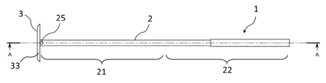
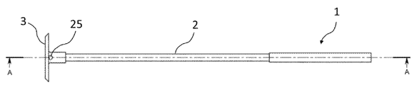
- FIG. 2 is a front view of the pipette tool according to the first embodiment.
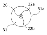
- FIG. 3 is a plan view of the pipette tool according to the first embodiment.
- FIG. 4 is a bottom view of the pipette tool according to the first embodiment.
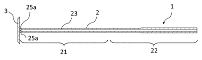
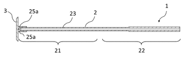
- FIG. 5 is a cross-sectional view taken along the line AA in FIG.
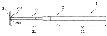
- FIG. 6 is a front view of the pipette tool according to the second embodiment.
- FIG. 7 is a cross-sectional view taken along the line AA in FIG.
- FIG. 8 is a front view of the pipette tool according to the third embodiment.
- FIG. 9 is a cross-sectional view taken along the line AA in FIG.
- FIG. 10 is a perspective view of the pipette tool according to the fourth embodiment.
- FIG. 11 is a perspective view of a conventional pipette tool.
- FIG. 12 is a front
- FIG. 1 is a perspective view of a pipette tool 1 according to one embodiment of the present invention (hereinafter referred to as “Embodiment 1”).
- the pipette tool 1 according to the first embodiment is a solution such as a culture solution in the centrifuge tube (above) while preventing the precipitated cells from floating after centrifuging the cell suspension in the centrifuge tube. It has a structure suitable for sucking Qing).
- the pipette tool 1 has a tubular portion 2 and a shield plate 3 attached to the tubular portion 2. The end surface of the first end portion 21 of the tubular portion 2 is fixed to the first main surface 31 of the shield plate 3.
- the tubular portion 2 has a first end portion 21 and a second end portion 22.
- the first end portion 21 has a length of less than half of the shortest distance between the end face of the first end portion 21 and the end face of the second end portion 22 from the end face of the first end portion 21 toward the second end portion 22. It is a part.
- the second end portion 22 has a length of less than half of the shortest distance between the end face of the first end portion 21 and the end face of the second end portion 22 from the end face of the second end portion 22 toward the first end portion 21. It is a part.
- a dispensing device or a suction device such as a pipetter or an aspirator can be attached to the second end portion 22.
- the solution can be sucked out from the centrifuge tube 6 containing the cell precipitate after centrifugation and the solution (supernatant) on the upper portion thereof.
- the tubular portion 2 has a length and an outer diameter (thickness) such that the shield plate 3 can be moved inside the tube body 61 of the centrifuge tube 6 along the long axis direction of the tube body 61. ) (See FIG. 12).
- the length of the tubular portion 2 is longer than the length of the tube body 61 in the major axis direction, and may be, for example, 50 to 400 mm, 75 to 300 mm, or 100 to 200 mm.
- the outer diameter of the tubular portion 2 is smaller than the inner diameter of the tube body 61, and may be, for example, 3 to 15 ⁇ mm, 3 to 10 ⁇ mm, or 3 to 8 ⁇ mm.
- the inner diameter of the tubular portion 2 may be, for example, 1.5 to 13.5 ⁇ mm, 1.5 to 8.5 ⁇ mm, or 1.5 to 6.5 ⁇ mm.
- the inner diameter of the tube body 61 of the centrifuge tube 6 is the maximum dimension of the inner circumference of the peripheral wall of the tube body 61 in the cross section of the body portion 64 of the tube body 61 orthogonal to the major axis 67 of the tube body 61.
- the outer diameter of the tubular portion 2 of the pipette tool 1 is the maximum dimension of the outer circumference of the peripheral wall 23 of the tubular portion 2 in the cross section of the tubular portion 2 orthogonal to the long axis 27 of the tubular portion 2.
- the inner diameter of the tubular portion 2 of the pipette tool 1 is the maximum dimension of the inner circumference of the peripheral wall 23 of the tubular portion 2 in the cross section of the tubular portion 2 orthogonal to the long axis 27 of the tubular portion 2.
- the maximum dimension in a circle is its diameter
- the maximum dimension in an ellipse is its major axis length
- the maximum dimension in a polygon is its circumscribed circle. The diameter of the circle.
- the tubular portion 2 according to the first embodiment has two first openings 25 on the side wall of the first end portion 21 (see FIG. 2).
- FIG. 2 one of the two first openings 25 is shown, and another first opening 25 is provided on the back surface side which is not shown in the figure.
- FIG. 3 shows a plan view of the pipette tool according to the first embodiment.
- the tubular portion 2 has a second opening 26 in the end surface 22b of the second end portion 22 that communicates with the internal space of the tubular portion 2.
- the two first openings 25 communicate with the internal space of the tubular portion 2 defined by the peripheral wall 23.
- the internal space of the tubular portion 2 communicates with the second opening 26 of the second end portion of the tubular portion 2.
- the pipette tool 1 When the pipette tool 1 according to the first embodiment is used to suck out the solution from the centrifuge tube 6 containing the centrifuged cell precipitate and the solution (supernatant) on the centrifuge, the pipette tool 1 is used as the centrifuge tube 6. The inside of the pipette is moved from the open end 63 to the closed end 65 along the long axis 67, and the shield plate 3 of the pipette tool 1 is immersed in the solution (supernatant) and further brought close to the cell precipitate. The solution is sucked from the first opening 25 of the pipette tool 1 located in the solution by, for example, the suction force provided by the dispensing device or the suction device attached to the second end portion 22 of the tubular portion 2.
- the sucked solution is discharged from the second opening 26 communicating with the internal space through the internal space of the tubular portion 2 communicating with the first opening 25.
- a liquid flow occurs in the solution in the centrifuge tube 6, but the shield plate 3 located close to the cell precipitate causes the cells to float from the cell precipitate due to the liquid flow. Can be prevented.
- the shield plate 3 of the pipette tool 1 can prevent the cells from floating from the cell precipitate when sucking the solution, and thus suppresses the cells from being sucked out together with the solution. This allows cells to be recovered stably and efficiently.
- the tubular portion 2 of the pipette tool 1 has sufficient internal space to contain the solution, centrifuge the pipette tool 1 with the solution in the centrifuge tube contained in the internal space of the pipette tool 1.
- the solution can be removed from the centrifuge tube by removing it from the separation tube.
- the volume of the internal space of the tubular portion 2 is increased by increasing the inner diameter of the tubular portion 2 and / or extending the length of the tubular portion 2.
- the tubular portion 2 according to the first embodiment has two first openings 25 that communicate with the internal space on the peripheral wall 23 of the first end portion 21.
- the number of the first openings 25 may be, for example, one, two, three, four or five.
- the two first openings 25 according to the first embodiment are provided at positions facing each other.
- the plurality of first openings 25 provided on the peripheral wall 23 of the first end portion 21 are arranged at intervals around the center point seen from the long axis direction of the tubular portion 2.
- the plurality of first openings 25 are arranged at equal intervals, for example, around the center point of the cylindrical portion 2 as viewed from the long axis direction.
- the two first openings 25 according to the first embodiment are provided so as to be in contact with the first main surface 31 of the shield plate 3.
- the surface of the wall surface 25a closest to the first main surface 31 is the first end portion 21 from the end surface of the first end portion 21 toward the end surface of the second end portion 22. It may be provided at a position of 10% or less, 5% or less, or 3% or less of the shortest distance between the end face of the surface and the end surface of the second end portion 22.
- the surface of the wall surface 25a closest to the first main surface 31 is located at a position of 0 to 20 mm, 0 to 10 mm, or 0 to 5 mm from the first main surface 3 of the shield plate 3. It may be provided in.
- the shape of the first opening 25 may be, for example, a circle, a polygon (eg, a hexagon, an octagon, and a decagon), or an ellipse.
- the size of the first opening 25 may be, for example, its maximum dimension of 1 to 5 mm, 1.5 to 4 mm or 2 to 3 mm.
- the outer peripheral 22a of the end surface 22b of the second end portion of the tubular portion 2 is formed. It is inside the outer circumference 31a of the first main surface 31 of the shield plate 3.
- the outer circumference of the end surface of the first end portion 21 of the tubular portion 2 according to the first embodiment is a shield plate when the first end portion 22 of the tubular portion 2 is viewed from the long axis direction of the tubular portion 2. It is inside the outer circumference 31a of the first main surface 31 of 3.
- the angle (acute angle) formed by the long axis 27 (see FIG. 12) of the tubular portion 2 and the first main surface 31 of the shield plate 3 is about 90 ° (for example, 85 ° to 90 °).
- the angle formed by the long axis 27 of the tubular portion and the first main surface 31 of the shield plate 3 may be, for example, 60 ° to 90 °, 70 ° to 90 °, or 80 ° to 90 °.
- the angle formed by the long axis 27 of the tubular portion and the first main surface 31 of the shield plate 3 may be, for example, 60 °, 65 °, 70 °, 75 °, 80 °, 85 ° or 90 °.
- the tubular portion 2 according to the first embodiment is a cylinder.
- the tubular portion 2 according to the present invention may be, for example, a polygonal prism (for example, a hexagonal prism, an octagonal prism and a ten-sided prism), an elliptical columnar column, or a cylindrical columnar shape.
- the tubular portion 2 according to the present invention may be partially or wholly provided with a taper whose diameter is reduced from the end surface 22b of the second end portion 22 toward the end surface of the first end portion 21.
- the thickness of the peripheral wall 23 of the tubular portion 2 may be, for example, 0.5 to 1 mm, 0.6 to 0.9 mm, or 0.7 to 0.8 mm. In one embodiment, the thickness of the peripheral wall 23 of the tubular portion 2 is constant between the first end portion 21 and the second end portion 22. In one embodiment, the thickness of the peripheral wall 23 of the tubular portion 2 does not have to be constant between the first end portion 21 and the second end portion 22. In one embodiment, the thickness of the peripheral wall 23 of the second end 22 is larger than the thickness of the peripheral wall 23 of the first end 21.
- the shield plate 3 according to the first embodiment has a shape and a size that allows the inside of the tube main body 61 of the centrifuge tube 6 to move along the long axis 67 (see FIG. 12).
- the maximum dimension of the outer circumference 31a of the first main surface of the shield plate 3 is smaller than, for example, the inner diameter of the tube body 61 of the centrifuge tube 6.
- the shield plate 3 has a first main surface 31, a second main surface 32 facing the first main surface 31, and a side surface 33 connecting the first main surface 31 and the second main surface 32.
- the thickness of the shield plate 3 may be, for example, 1 to 7 mm, 2 to 5 mm, or 2 to 4 mm.
- the thickness of the shield plate 3 may be, for example, 1 mm, 2 mm, 3 mm, 4 mm, 5 mm, 6 mm, or 7 mm.
- the thickness of the shield plate 3 is constant over the entire shield plate 3. In one embodiment, the thickness of the shield plate 3 is not constant over the entire shield plate 3.
- the shield plate 3 according to the first embodiment is a columnar shape whose outer periphery gradually decreases from the first main surface 31 toward the second main surface 32.
- the first main surface 31 and the second main surface 32 of the shield plate 3 are each circular.
- the shield plate 3 according to the present invention may be, for example, a polygonal prism (for example, a hexagonal prism, an octagonal prism and a 10-sided prism), an elliptical columnar or a cylindrical columnar shape.
- the first main surface 31 and the second main surface 32 of the shield plate 3 according to the present invention may be, for example, polygonal (for example, hexagonal, octagonal and decagonal) or elliptical, respectively.
- the shield plate 3 is provided with a taper whose diameter is reduced from the first main surface 31 to the second main surface 32.
- the side surface 33 of the shield plate 3 is a tapered surface whose diameter is reduced from the first main surface toward the second main surface.
- the taper angle ⁇ of the shield plate 3 or the taper angle ⁇ of the side surface 33 of the shield plate 3 may be, for example, 20 ° to 160 °, 40 ° to 140 °, or 60 ° to 120 °.
- the angle ⁇ is, for example, 20 °, 30 °, 40 °, 50 °, 60 °, 70 °, 80 °, 90 °, 100 °, 110 °, 120 °, 130 °, 140 °, 150 ° or 160 °. May be.
- the end surface of the first end portion 21 of the tubular portion 2 is fixed to the geometric center of the first main surface 31 of the shield plate 3 (see FIG. 3).
- the tubular portion 2 according to the present invention may be fixed to the center of, for example, the first main surface 31.
- the center of the first main surface 31 means a range of the maximum dimension of the first main surface ⁇ 10% or less from the geometric center in the shape of the first main surface 31.
- the shield plate 3 is made of, for example, a transparent, translucent or non-transparent plastic material, rubber or glass.
- the shield plate 3 is made of, for example, metal.
- the plastic material include plastics commonly used in the pharmaceutical or research fields, such as polystyrene, polycarbonate, polyethylene, polypropylene and polyethylene terephthalate.
- the rubber include rubber commonly used in the pharmaceutical field or the research field, for example, butyl rubber, isoprene rubber, butadiene rubber, and silicone rubber.
- the glass or metal include glass or metal commonly used in the pharmaceutical or research fields.
- the pipette tool 1 according to the present invention can be manufactured according to a known method.
- the pipette tool 1 can be manufactured, for example, by injection molding.
- the pipette tool 1 can be manufactured integrally, or can be manufactured by combining two or more members. When the pipette tool 1 is manufactured by combining two or more members, the two or more members may be made of the same material or may be made of different materials.
- the pipette tool 1 according to the first embodiment can be manufactured by integrally forming the shield plate 3 and the tubular portion 2.
- FIG. 6 shows a front view of the pipette tool 1 according to another embodiment of the present invention (hereinafter referred to as “Embodiment 2”).
- the second embodiment will be described with reference to FIG. 6, but the differences from the first embodiment will be mainly described, and the same matters will be omitted.
- the outer diameter of the tubular portion 2 is substantially constant from the first end portion 21 to the second end portion 22 (see FIG. 2).
- the outer diameter of the tubular portion 2 is the second end between the end face of the first end portion 21 and the end face of the second end portion 22.
- a taper is provided so that the diameter is reduced from the end surface of the portion 22 toward the end surface of the first end portion 21.
- the inner diameter of the tubular portion 2 is a constant size from the first end portion 21 to the second end portion 22 (see FIG. 5). As shown in FIG. 7, in the pipette tool 1 according to the second embodiment, the inner diameter of the tubular portion 2 is the second end portion between the end face of the first end portion 21 and the end face of the second end portion 22. The diameter is reduced from the end face of 22 toward the end face of the first end portion 21.
- FIG. 8 shows a front view of the pipette tool 1 according to another embodiment of the present invention (hereinafter referred to as “Embodiment 3”).
- the third embodiment will be described with reference to FIG. 8, but the differences from the first embodiment will be mainly described, and the same matters will be omitted.
- the pipette tool 1 according to the first embodiment has a cylindrical portion 2 and a shield plate 3 integrally formed (see FIG. 1). As shown in FIG. 9, the pipette tool 1 according to the third embodiment assembles two members, a first member mainly formed of a tubular portion 2 and a second member mainly formed of a shield plate 3. Formed by Both the first member and the second member may be formed of the same material, or may be formed of different materials.
- FIG. 10 shows a perspective view of the pipette tool 1 according to another embodiment of the present invention (hereinafter referred to as “Embodiment 4”).
- the fourth embodiment will be described with reference to FIG. 10, but the differences from the first embodiment will be mainly described, and the same matters will be omitted.
- the tubular portion 2 of the pipette tool 1 according to the first embodiment is longer than the length in the long axis direction of the centrifuge tube.
- a dispensing device or a suction device such as a pipetter or an aspirator can be attached to the second end portion 22 of the tubular portion 2.
- the tubular portion 2 of the pipette tool 1 according to the fourth embodiment is sufficiently shorter than the length in the long axis direction of the centrifuge tube.
- the tip portion 41 (see FIG. 11) of the conventional pipette 4 can be attached to the second end portion 22 of the tubular portion 2.
- the pipette tool 1 according to the fourth embodiment to which the conventional pipette 4 is attached can be used in the same manner as the usage method described in the present specification for the pipette tool 1 according to the first to third embodiments.
- FIG. 12 shows a front view of the centrifuge kit 5 according to another embodiment of the present invention (hereinafter referred to as “Embodiment 5”).
- the centrifuge kit 5 includes the pipette tool 1 disclosed herein and the centrifuge tube 6.
- the centrifuge kit 5 may include a plurality of pipette tools 1 and a plurality of centrifuge tubes 6.
- the centrifuge tube 6 has a tube body 61 and a screw cap 62.
- the tube body 61 has a peripheral wall that defines an internal space.
- the peripheral wall of the tube main body 61 is composed of an open end portion 63, a main body portion 64, and a closed end portion 65.
- the inner peripheral shape of the cross section of the tube body 61 orthogonal to the major axis 67 of the tube body 61 is, for example, a circle, an ellipse, or a polygon (for example, a hexagon, an octagon, and a decagon).
- the tube body 61 according to the present invention can accommodate, for example, 10 to 250 ml, 20 to 200 ml, or 50 to 150 ml of a solution in its internal space.
- the length of the tube body 61 in the major axis direction may be, for example, 25 to 350 mm, 50 to 250 mm, or 75 to 150 mm.
- the inner diameter of the tube body 61 may be 10 to 100 ⁇ mm, 20 to 80 ⁇ mm, or 30 to 70 ⁇ mm.
- the thickness of the peripheral wall of the tube body 61 may be, for example, 0.5 to 3 mm, 1 to 2.5 mm, or 1.5 to 2 mm. In one embodiment, the thickness of the peripheral wall of the tube body 61 is constant between its open end 63 and its closed end 65. In one embodiment, the thickness of the peripheral wall of the tube body 61 is not constant between its open end 63 and its closed end 65.
- the open end 63 of the tube body 61 according to the fifth embodiment has a screw receiver for receiving the screw cap 62.
- the centrifuge tube 6 is opened and closed using a screw cap 62.
- the centrifuge tube 6 according to the present invention may be opened / closed by a hinge cap or may be opened / closed by using a screw cap.
- the shield plate 3 of the pipette tool 1 according to the fifth embodiment has a shape and a size that allows the inside of the tube main body 61 of the centrifuge tube 6 to move along the long axis 67 thereof.
- the shield plate 3 of the pipette tool 1 according to the fifth embodiment has a first main surface 31 having a maximum outer size smaller than the inner diameter of the tube body 61. Further, the shield plate 3 has a first main surface 31 having a maximum outer size smaller than the inner diameter of the main body portion 64 of the tube main body 61.
- the maximum dimension of the outer peripheral portion 31a of the first main surface of the shield plate 3 is, for example, 5 to 60 ⁇ mm, 10 to 50 ⁇ mm, or 15 to 40 ⁇ mm smaller than the inner diameter of the tube main body 61 or the main body portion 64 thereof.
- the maximum dimension of the outer circumference 31a of the first main surface of the shield plate 3 is smaller than, for example, the inner diameter of the opening of the hinge cap.
- the opening of the hinge cap has a peripheral wall defining the opening.
- the inner diameter of the opening of the hinge cap is the maximum dimension of the inner circumference of the peripheral wall defining the opening in a cross section orthogonal to the central axis of the opening surface of the opening.
- the outer peripheral shapes of the first main surface 31 and the second main surface 32 of the shield plate 3 of the pipette tool 1 according to the fifth embodiment are circular, and the inner circumference of the cross section of the tube body 61 orthogonal to the long axis of the centrifuge tube 6 is formed. It is the same as the shape.
- the outer peripheral shapes of the first main surface 31 and the second main surface 32 of the shield plate 3 are, for example, a circle, an ellipse, or a polygon (for example, a hexagon, an octagon, and a decagon).
- the outer peripheral shapes of the first main surface 31 and the second main surface 32 of the shield plate 3 are the same as the inner peripheral shape of the cross section of the tube body 61 orthogonal to the long axis of the centrifuge tube 6. Well, it doesn't have to be the same.
- the length of the pipette tool 1 in the major axis direction is, for example, 10 to 100 mm, 15 to 80 mm, or 20 to 60 mm longer than the length of the centrifuge tube 6 in the major axis direction.
- the shield plate 31 of the pipette tool 1 has a first main surface 31 and a second main surface 32 facing the first main surface 31, and a first.
- a taper is provided that reduces the diameter from the main surface 31 to the second main surface 32.
- the shield plate 31 has a side surface 33 connecting the first main surface 31 and the second main surface 32, and the side surface 33 is a tapered surface whose diameter is reduced from the first main surface 31 to the second main surface 32. ing.
- the taper angle ⁇ of the shield plate 3 or the taper angle ⁇ of the side surface 33 of the shield plate 3 may be, for example, 20 ° to 160 °, 40 ° to 140 °, or 60 ° to 120 °.
- the angle ⁇ is, for example, 20 °, 30 °, 40 °, 50 °, 60 °, 70 °, 80 °, 90 °, 100 °, 110 °, 120 °, 130 °, 140 °, 150 ° or 160 °. May be.
- the closed end portion 65 of the centrifuge tube 6 according to the fifth embodiment is provided with a taper whose diameter is reduced from its upper portion 68 toward its tip 69.
- the taper angle ⁇ at the closed end portion 65 of the tube body 61 may be, for example, 20 ° to 160 °, 40 ° to 140 °, or 60 ° to 120 °.
- the angle ⁇ is, for example, 20 °, 30 °, 40 °, 50 °, 60 °, 70 °, 80 °, 90 °, 100 °, 110 °, 120 °, 130 °, 140 °, 150 ° or 160 °. May be.
- the taper angle ⁇ in the shield plate 3 of the pipette tool 1 and the taper angle ⁇ in the closed end portion 65 of the tube body 61 are equal to each other.
- the taper angle ⁇ and the taper angle ⁇ may or may not be equal.
- the difference between the taper angle ⁇ and the taper angle ⁇ may be, for example, within 15 °, within 10 °, within 5 °, or within 3 °.
- the solution is taken from the centrifuge tube 6 containing the centrifuged cell precipitate (present around the tip 69 of the closed end 65 of the centrifuge tube 6) and the solution (supernatant) above it.
- the pipette tool 1 operates as follows. First, the pipette tool 1 is inserted from the open end 63 into the centrifuge tube 6 and moved from the open end 63 to the closed end 65 along the long axis 67.
- the shield plate 3 of the pipette tool 1 is immersed in a solution (supernatant) and further brought close to the cell precipitate to bring the shield plate 3 of the pipette tool 1 into contact with the inner surface of the closed end portion 65 of the centrifuge tube 6. ..
- the shield plate 3 of the pipette tool 1 Since the shield plate 3 of the pipette tool 1 is held at that position (also referred to as a contact position or a contact position), it cannot move further to the tip 69 of the closed end portion 65.
- the solution (supernatant) is sucked out from the first opening 25 of the pipette tool 1
- the solution above the shield plate 3 can be easily sucked out, but the cell precipitate present in the space below the shield plate 3 Is prevented from being sucked out together with the solution by the shield plate 3 located between the first opening 25. Thereby, the sucking out of the cell precipitate can be suppressed.
- the shield plate 3 of the pipette tool 1 is held at a position in contact with the inner surface of the closed end portion 65, it is possible to stabilize the variation in the procedure depending on the user, particularly the position of the shield plate 3 when the solution is sucked out. Therefore, the cells can be recovered more stably.
- the shield plate 3 when the shield plate 3 comes into contact with the inner surface of the centrifuge tube 6, it is preferable that the shield plate 3 covers almost the entire space on the tip 69 side of the centrifuge tube 6. That is, when a cross section is defined that passes through a position where the inner surface of the closed end portion 65 of the centrifuge tube 6 and the shield plate 3 are in contact with each other and is orthogonal to the long axis 67 of the centrifuge tube 6, the centrifuge tube 6 in the cross section is defined. It is preferable that the inner peripheral shape and the outer peripheral shape of the shield plate 3 in the cross section are the same.
- the shield plate 3 can cover the space below the position where the shield plate 3 is in contact, that is, the space near the tip 69 of the closed end portion 65 containing the cell precipitate. Therefore, when the solution (supernatant) is sucked out from the first opening 25 of the pipette tool 1, it is effective that the cell precipitate existing in the space below the shield plate 3 is sucked out together with the solution. Can be suppressed.
- the difference between the taper angle ⁇ at the closed end 65 of the tube body 61 and the taper angle ⁇ at the shield plate 3 of the pipette tool 1 is within 15 °, preferably within 10 °, preferably within 5 ° or within 3 °.
- the taper angle ⁇ and the taper angle ⁇ are equal, the contact area between the side surface of the shield plate 3 and the inner surface of the centrifuge tube 6 increases. Therefore, it is possible to further suppress the variation in the procedure depending on the user, and thereby the cells can be recovered more stably.
- the tube body 61 or cap of the centrifuge tube 6 according to the present invention is formed of, for example, a transparent, translucent or non-transparent plastic material.
- the plastic material include plastics commonly used in the pharmaceutical or research fields, such as polystyrene, polycarbonate, polyethylene, polypropylene and polyethylene terephthalate.
- the tube body 61 and the cap may be made of different materials or may be made of the same material.
- the centrifuge tube according to the present invention can be manufactured according to a known method.
- the centrifuge tube can be manufactured, for example, by injection molding.
- Example 1 A cell suspension containing cultured mammalian cells was prepared. The number of cells contained in 80 ml of the cell suspension was measured. As a result, 80 ml of the cell suspension contained about 1.0 ⁇ 107 cells. After dispensing 80 ml of the cell suspension into a centrifuge tube, the cells were separated into a cell precipitate and a solution (supernatant) by centrifugation.
- the pipette tool according to the first embodiment is inserted from the open end of the centrifuge tube, and the shield plate of the pipette tool and the inner surface of the closed end of the centrifuge tube are in contact with each other (also referred to as “contact position”).
- Example 2 Substantially the same test as in Example 1 was performed except that the position for sucking the solution (supernatant) was changed from the non-contact position to the contact position using a pipette tool.
- the cell recovery rate (%) was calculated by dividing the number of recovered cells by the number of cells (1.0 ⁇ 107 ) contained in 80 ml of the cell suspension before centrifugation. The results are shown in Table 1.
- the variation in the cell recovery rate when the pipette tool according to the present invention is used in the non-contact position is the variation in the cell recovery rate when the conventional pipette is used in the non-contact position (comparison). It was smaller than the example).
- Example 2 the variation in the cell recovery rate when the pipette tool according to the present invention is used in the contact position (Example 2) is the variation in the cell recovery rate when the pipette tool according to the present invention is used in the non-contact position. It was even smaller than that of (Example 1).
Landscapes
- Health & Medical Sciences (AREA)
- Chemical & Material Sciences (AREA)
- Clinical Laboratory Science (AREA)
- Chemical Kinetics & Catalysis (AREA)
- General Health & Medical Sciences (AREA)
- Life Sciences & Earth Sciences (AREA)
- Analytical Chemistry (AREA)
- Hematology (AREA)
- Bioinformatics & Cheminformatics (AREA)
- Wood Science & Technology (AREA)
- Organic Chemistry (AREA)
- Zoology (AREA)
- Engineering & Computer Science (AREA)
- Biotechnology (AREA)
- Sustainable Development (AREA)
- Microbiology (AREA)
- Biomedical Technology (AREA)
- Biochemistry (AREA)
- General Engineering & Computer Science (AREA)
- Genetics & Genomics (AREA)
- Molecular Biology (AREA)
- Centrifugal Separators (AREA)
- Apparatus Associated With Microorganisms And Enzymes (AREA)
Priority Applications (3)
| Application Number | Priority Date | Filing Date | Title |
|---|---|---|---|
| US18/031,417 US20230381769A1 (en) | 2020-10-16 | 2021-10-15 | Pipette Tool and Kit Used in Centrifugation |
| JP2022557480A JPWO2022080485A1 (https=) | 2020-10-16 | 2021-10-15 | |
| EP21880220.5A EP4230717A4 (en) | 2020-10-16 | 2021-10-15 | PIPETTE TOOL AND CENTRIFUGATION KIT |
Applications Claiming Priority (2)
| Application Number | Priority Date | Filing Date | Title |
|---|---|---|---|
| JP2020174831 | 2020-10-16 | ||
| JP2020-174831 | 2020-10-16 |
Publications (1)
| Publication Number | Publication Date |
|---|---|
| WO2022080485A1 true WO2022080485A1 (ja) | 2022-04-21 |
Family
ID=81208105
Family Applications (1)
| Application Number | Title | Priority Date | Filing Date |
|---|---|---|---|
| PCT/JP2021/038239 Ceased WO2022080485A1 (ja) | 2020-10-16 | 2021-10-15 | ピペット用具および遠心分離用キット |
Country Status (4)
| Country | Link |
|---|---|
| US (1) | US20230381769A1 (https=) |
| EP (1) | EP4230717A4 (https=) |
| JP (1) | JPWO2022080485A1 (https=) |
| WO (1) | WO2022080485A1 (https=) |
Citations (10)
| Publication number | Priority date | Publication date | Assignee | Title |
|---|---|---|---|---|
| JPS5119887U (https=) * | 1974-07-31 | 1976-02-13 | ||
| JPH11153605A (ja) * | 1997-11-19 | 1999-06-08 | Tokuyama Sekisui Ind Corp | 検体吸入用ノズルチップ |
| JP2001108506A (ja) * | 1999-10-13 | 2001-04-20 | Aloka Co Ltd | 層境界面検出装置 |
| WO2006016528A1 (ja) * | 2004-08-12 | 2006-02-16 | Nikkyo Technos Co., Ltd. | ピペットチップ |
| JP2008278791A (ja) * | 2007-05-10 | 2008-11-20 | Tokyo Medical & Dental Univ | 核酸増幅装置、方法および細胞培養・核酸増幅方法 |
| JP2008279031A (ja) * | 2007-05-10 | 2008-11-20 | Horiba Ltd | 採血具 |
| JP2009118798A (ja) * | 2007-11-16 | 2009-06-04 | Tokyo Medical & Dental Univ | 核酸増幅装置、方法および細胞培養・核酸増幅方法 |
| JP2010038876A (ja) * | 2008-08-08 | 2010-02-18 | Enplas Corp | チューブ及び遠心分離装置 |
| JP2016185127A (ja) | 2015-03-27 | 2016-10-27 | 日本写真印刷株式会社 | ピペット用器具 |
| WO2018092513A1 (ja) * | 2016-11-18 | 2018-05-24 | 株式会社村田製作所 | 細胞培養液回収フィルタユニット、細胞培養液回収方法、及び細胞培養液回収キット |
Family Cites Families (4)
| Publication number | Priority date | Publication date | Assignee | Title |
|---|---|---|---|---|
| US9574977B2 (en) * | 2013-02-26 | 2017-02-21 | Innova Prep | Liquid to liquid biological particle concentrator with disposable fluid path |
| RU2654666C2 (ru) * | 2013-05-24 | 2018-05-21 | Оккам Байолэбс, Инк. | Система и способ сбора образца нуклеиновой кислоты |
| WO2016073832A1 (en) * | 2014-11-07 | 2016-05-12 | Theranos, Inc. | Improved methods, devices, and systems for mixing fluids |
| CH713443A2 (de) * | 2017-02-08 | 2018-08-15 | Roth Felix | Medizinalröhrchen. |
-
2021
- 2021-10-15 JP JP2022557480A patent/JPWO2022080485A1/ja active Pending
- 2021-10-15 US US18/031,417 patent/US20230381769A1/en active Pending
- 2021-10-15 EP EP21880220.5A patent/EP4230717A4/en active Pending
- 2021-10-15 WO PCT/JP2021/038239 patent/WO2022080485A1/ja not_active Ceased
Patent Citations (10)
| Publication number | Priority date | Publication date | Assignee | Title |
|---|---|---|---|---|
| JPS5119887U (https=) * | 1974-07-31 | 1976-02-13 | ||
| JPH11153605A (ja) * | 1997-11-19 | 1999-06-08 | Tokuyama Sekisui Ind Corp | 検体吸入用ノズルチップ |
| JP2001108506A (ja) * | 1999-10-13 | 2001-04-20 | Aloka Co Ltd | 層境界面検出装置 |
| WO2006016528A1 (ja) * | 2004-08-12 | 2006-02-16 | Nikkyo Technos Co., Ltd. | ピペットチップ |
| JP2008278791A (ja) * | 2007-05-10 | 2008-11-20 | Tokyo Medical & Dental Univ | 核酸増幅装置、方法および細胞培養・核酸増幅方法 |
| JP2008279031A (ja) * | 2007-05-10 | 2008-11-20 | Horiba Ltd | 採血具 |
| JP2009118798A (ja) * | 2007-11-16 | 2009-06-04 | Tokyo Medical & Dental Univ | 核酸増幅装置、方法および細胞培養・核酸増幅方法 |
| JP2010038876A (ja) * | 2008-08-08 | 2010-02-18 | Enplas Corp | チューブ及び遠心分離装置 |
| JP2016185127A (ja) | 2015-03-27 | 2016-10-27 | 日本写真印刷株式会社 | ピペット用器具 |
| WO2018092513A1 (ja) * | 2016-11-18 | 2018-05-24 | 株式会社村田製作所 | 細胞培養液回収フィルタユニット、細胞培養液回収方法、及び細胞培養液回収キット |
Also Published As
| Publication number | Publication date |
|---|---|
| EP4230717A1 (en) | 2023-08-23 |
| EP4230717A4 (en) | 2024-11-20 |
| JPWO2022080485A1 (https=) | 2022-04-21 |
| US20230381769A1 (en) | 2023-11-30 |
Similar Documents
| Publication | Publication Date | Title |
|---|---|---|
| EP2146794B1 (en) | Buoy suspension fractionation system | |
| US4829006A (en) | Centrifugation vial and cluster tray | |
| KR101289535B1 (ko) | 원심분리관 | |
| US4968625A (en) | Centrifrugation vial and cluster tray | |
| EP0959989B1 (en) | Cell washing device and method | |
| JP6218430B2 (ja) | デフレクタシールドを備えた遠心分離チャンバ | |
| CN103260768A (zh) | 分离容器及分离方法 | |
| JP2013236631A (ja) | 積層可能な細胞濾過器 | |
| KR100354341B1 (ko) | 상하 개폐식 원심 분리 튜브 | |
| CN213943196U (zh) | 一种封闭式离心管 | |
| WO2015104797A1 (ja) | 運動性精子選別デバイス | |
| WO2022080485A1 (ja) | ピペット用具および遠心分離用キット | |
| KR20150112216A (ko) | 분리가능한 이중 샘플 튜브 | |
| CN106796216B (zh) | 用于分离细胞的装置和方法 | |
| CN212595800U (zh) | 一种封闭式离心装置 | |
| US20220268671A1 (en) | A device for immobilizing rare cells for cytology | |
| CN211142022U (zh) | 分离管和分离管组件 | |
| JP6836235B2 (ja) | 細胞搬送用容器 | |
| CN113996366B (zh) | 一种封闭式离心装置 | |
| JP2016077186A (ja) | 培養容器及びその下部容器 | |
| CN209810213U (zh) | 离心管 | |
| CN209968442U (zh) | 一种可提高目标分离物获得率的离心管 | |
| CN205420394U (zh) | 大规格细胞分离管 | |
| WO2013074138A1 (en) | Systems to control fluid flow in density-based fluid separation | |
| CN106967590A (zh) | 大规格细胞分离管 |
Legal Events
| Date | Code | Title | Description |
|---|---|---|---|
| 121 | Ep: the epo has been informed by wipo that ep was designated in this application |
Ref document number: 21880220 Country of ref document: EP Kind code of ref document: A1 |
|
| ENP | Entry into the national phase |
Ref document number: 2022557480 Country of ref document: JP Kind code of ref document: A |
|
| NENP | Non-entry into the national phase |
Ref country code: DE |
|
| ENP | Entry into the national phase |
Ref document number: 2021880220 Country of ref document: EP Effective date: 20230516 |