WO2022079837A1 - 電動機、送風機および空気調和装置 - Google Patents
電動機、送風機および空気調和装置 Download PDFInfo
- Publication number
- WO2022079837A1 WO2022079837A1 PCT/JP2020/038795 JP2020038795W WO2022079837A1 WO 2022079837 A1 WO2022079837 A1 WO 2022079837A1 JP 2020038795 W JP2020038795 W JP 2020038795W WO 2022079837 A1 WO2022079837 A1 WO 2022079837A1
- Authority
- WO
- WIPO (PCT)
- Prior art keywords
- cover member
- tube
- mold resin
- lead wire
- motor according
- Prior art date
- Legal status (The legal status is an assumption and is not a legal conclusion. Google has not performed a legal analysis and makes no representation as to the accuracy of the status listed.)
- Ceased
Links
Images


Classifications
-
- F—MECHANICAL ENGINEERING; LIGHTING; HEATING; WEAPONS; BLASTING
- F04—POSITIVE - DISPLACEMENT MACHINES FOR LIQUIDS; PUMPS FOR LIQUIDS OR ELASTIC FLUIDS
- F04D—NON-POSITIVE-DISPLACEMENT PUMPS
- F04D25/00—Pumping installations or systems
- F04D25/02—Units comprising pumps and their driving means
- F04D25/06—Units comprising pumps and their driving means the pump being electrically driven
- F04D25/0693—Details or arrangements of the wiring
-
- H—ELECTRICITY
- H02—GENERATION; CONVERSION OR DISTRIBUTION OF ELECTRIC POWER
- H02K—DYNAMO-ELECTRIC MACHINES
- H02K5/00—Casings; Enclosures; Supports
- H02K5/04—Casings or enclosures characterised by the shape, form or construction thereof
- H02K5/22—Auxiliary parts of casings not covered by groups H02K5/06-H02K5/20, e.g. shaped to form connection boxes or terminal boxes
- H02K5/225—Terminal boxes or connection arrangements
-
- F—MECHANICAL ENGINEERING; LIGHTING; HEATING; WEAPONS; BLASTING
- F24—HEATING; RANGES; VENTILATING
- F24F—AIR-CONDITIONING; AIR-HUMIDIFICATION; VENTILATION; USE OF AIR CURRENTS FOR SCREENING
- F24F1/00—Room units for air-conditioning, e.g. separate or self-contained units or units receiving primary air from a central station
- F24F1/0007—Indoor units, e.g. fan coil units
- F24F1/0018—Indoor units, e.g. fan coil units characterised by fans
- F24F1/0029—Axial fans
-
- F—MECHANICAL ENGINEERING; LIGHTING; HEATING; WEAPONS; BLASTING
- F24—HEATING; RANGES; VENTILATING
- F24F—AIR-CONDITIONING; AIR-HUMIDIFICATION; VENTILATION; USE OF AIR CURRENTS FOR SCREENING
- F24F1/00—Room units for air-conditioning, e.g. separate or self-contained units or units receiving primary air from a central station
- F24F1/06—Separate outdoor units, e.g. outdoor unit to be linked to a separate room comprising a compressor and a heat exchanger
- F24F1/38—Fan details of outdoor units, e.g. bell-mouth shaped inlets or fan mountings
-
- H—ELECTRICITY
- H02—GENERATION; CONVERSION OR DISTRIBUTION OF ELECTRIC POWER
- H02K—DYNAMO-ELECTRIC MACHINES
- H02K5/00—Casings; Enclosures; Supports
- H02K5/04—Casings or enclosures characterised by the shape, form or construction thereof
- H02K5/10—Casings or enclosures characterised by the shape, form or construction thereof with arrangements for protection from ingress, e.g. water or fingers
Definitions
- This disclosure relates to motors, blowers and air conditioners.
- the present disclosure has been made to solve the above-mentioned problems, and an object thereof is to suppress the intrusion of water into the motor.
- the electric motor of the present disclosure includes a rotor, a stator surrounding the rotor, a circuit board attached to the stator, a mold resin portion covering the stator and the circuit board, and a lead connected to the circuit board and pulled out from the mold resin portion to the outside. It has a wire and a cover member attached to a mold resin portion and made of resin. A storage space for accommodating the lead wire is formed by the cover member and the outer peripheral surface of the mold resin portion. The cover member has a hole for pulling the lead wire out of the accommodation space.
- the lead wire drawn from the mold resin portion is accommodated in the accommodation space formed by the cover member and the outer peripheral surface of the mold resin portion, it is possible to suppress the intrusion of water into the motor. can.
- FIG. It is a perspective view which shows the electric motor of Embodiment 1.
- FIG. It is sectional drawing which shows the electric motor of Embodiment 1.
- FIG. It is a top view which shows the state which attached the circuit board to the stator of Embodiment 1.
- FIG. It is a figure which looked at the electric motor of Embodiment 1 from the non-load side.
- It is a notch perspective view which shows the cover member, the mouth part and the lead wire of Embodiment 1.
- FIG. It is a side view which shows the electric motor of Embodiment 1.
- FIG. It is sectional drawing which shows the cover member, the opening part and the lead wire of Embodiment 1.
- FIG. 1 It is a schematic diagram (A), (B) for demonstrating the relationship between the end surface of the cover member of Embodiment 1 and the outer peripheral surface of a mold resin part.
- FIG. 2 It is a notch perspective view which shows the cover member, the mouth part and the lead wire of Embodiment 2.
- FIG. 2 It is a side view which shows the electric motor of Embodiment 2.
- FIG. 2 It is sectional drawing which shows the cover member, the opening part and the lead wire of Embodiment 2.
- FIG. It is sectional drawing which shows the cover member, the opening part and the lead wire of Embodiment 3.
- FIG. It is a side view which shows the electric motor of Embodiment 4.
- FIG. 1 is a perspective view showing an electric motor 1 according to the first embodiment.
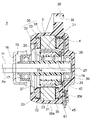
- FIG. 2 is a cross-sectional view showing the electric motor 1 of the first embodiment.
- the electric motor 1 includes a rotor 20, a stator 30 provided so as to surround the rotor 20, a circuit board 4 attached to the stator 30, and a mold resin portion covering the stator 30 and the circuit board 4. 35 and.
- the rotor 20 has a shaft 11.
- the rotation axis of the rotor 20, that is, the central axis of the shaft 11, is defined as the central axis Ax.
- the stator 30 and the circuit board 4 are covered with the mold resin portion 35 to form the mold stator 3.
- the direction of the central axis Ax is referred to as "axial direction”.
- the circumferential direction centered on the central axis Ax is referred to as a “circumferential direction” and is indicated by an arrow R1 in FIG. 3 and the like.
- the radial direction centered on the central axis Ax is referred to as "diametrical direction”.
- the shaft 11 protrudes from the stator 30 to the left side in FIG. 2, and for example, an impeller of a blower fan is attached to the protruding portion. Therefore, the protruding side (left side in FIG. 2) of the shaft 11 is referred to as a “load side”, and the opposite side (right side in FIG. 2) is referred to as a “non-load side”.
- the motor 1 is attached to an installation portion such as a frame 109 (FIG. 22 (B)) of the outdoor unit 101 of the air conditioner 100, for example. It is desirable that the central axis Ax is horizontal with the motor 1 attached to the installation portion.
- the rotor 20 has the shaft 11, an annular rotor core 21 surrounding the shaft 11, a plurality of rotor magnets (permanent magnets) 23 attached to the rotor core 21, and a resin portion 25 for supporting the rotor core 21.
- the rotor core 21 is composed of a laminated body in which a plurality of electromagnetic steel sheets are laminated in the axial direction and fixed by caulking or the like.
- the rotor core 21 has a plurality of magnet insertion holes 22 in the circumferential direction.
- a rotor magnet 23 is inserted into each magnet insertion hole 22.
- the rotor magnet 23 is a rare earth magnet containing, for example, Nd (neodymium), Fe (iron) and B (boron).
- the rotor 20 is a normal pole type rotor in which all magnetic poles are composed of a rotor magnet 23.
- the rotor 20 may be a sequential pole type rotor having a magnet magnetic pole composed of a rotor magnet 23 and a pseudo magnetic pole composed of a part of the rotor core 21.
- the resin portion 25 is provided so as to cover the shaft 11 and supports the rotor core 21.
- the resin portion 25 is made of a thermoplastic resin such as PBT (polybutylene terephthalate).
- a hollow portion 25a may be formed in the resin portion 25.
- An annular sensor magnet 26 is attached to the counterload side of the rotor 20 and is held by the resin portion 25.
- the stator 30 is arranged radially outside the rotor 20 and surrounds the rotor 20.
- the stator 30 has an annular stator core 31, an insulator 33 attached to the stator core 31, and a coil 32 wound around the stator core 31 via the insulator 33.
- the stator core 31 is composed of a laminated body in which a plurality of electromagnetic steel sheets are laminated in the axial direction and fixed by caulking or the like.
- the insulator 33 insulates the stator core 31 and the coil 32, and is made of a thermoplastic resin such as PBT.
- the insulator 33 has an inner wall portion and an outer wall portion that support the coil 32 from both sides in the radial direction.
- a plurality of protrusions 33a (FIG. 3) for fixing the circuit board 4 are arranged on the outer wall portion of the insulator 33.
- the protrusion 33a engages with a mounting hole 44 (FIG. 3) formed in the circuit board 4.
- the coil 32 is formed, for example, by winding a magnet wire around the stator core 31.
- the coil 32 is a three-phase winding composed of U-phase, V-phase and W-phase coils.
- the coil 32 is connected to a terminal 32a (FIG. 3) arranged on the outer wall portion of the insulator 33 by fusing (heat caulking), soldering, or the like.
- the mold resin portion 35 covers the outer circumference of the stator 30 and the non-load side.
- the mold resin portion 35 also covers the circuit board 4 attached to the stator 30.
- the mold resin portion 35 is made of a thermosetting resin such as BMC (bulk molding compound), for example.
- the mold resin portion 35 has a bearing support portion 36 on the non-load side and an opening 37 on the load side.
- the rotor 20 is inserted inside the stator 30 through the opening 37.
- a metal bracket 15 is attached to the opening 37 of the mold resin portion 35.
- one bearing 17 is held by the bracket 15, and the other bearing 18 is held by the bearing support portion 36.
- a cap 16 for preventing water or the like from entering the bearing 17 is attached to the shaft 11.
- the mold resin portion 35 has a leg portion 38 extending radially outward from the outer peripheral surface 35a thereof.
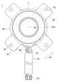
- the leg portion 38 is a portion for mounting the electric motor 1 to the installation portion, and has a mounting hole 39 through which a fixing tool such as a screw is inserted.
- the installation unit is, for example, a frame 109 (FIG. 22 (B)) of the outdoor unit 101.
- four legs 38 are provided (see FIG. 4), but the number is not limited to four.
- circuit board 4 is arranged on one side in the axial direction with respect to the stator 30.
- the circuit board 4 is arranged on the counterload side (right side in FIG. 2) of the stator 30, but may be arranged on the load side (left side in FIG. 2).
- FIG. 3 is a plan view showing a state in which the circuit board 4 is attached to the stator 30.
- the circuit board 4 is, for example, a printed circuit board.
- the printed circuit board has a wiring pattern made of a conductor formed on a plate-shaped base material having an insulating property, and through holes may be formed if necessary.
- the circuit board 4 is an annular shape centered on the central axis Ax.
- the circuit board 4 has an inner peripheral edge 4a which is a radial inner edge and an outer peripheral edge 4b which is a radial outer edge.
- an outer peripheral edge 4b of the circuit board 4 a plurality of mounting holes 44 that engage with the protrusion 33a described above are formed.
- the drive circuit 41 is composed of a power transistor and controls the rotation of the rotor 20.
- the Hall element 42 detects the magnetic flux from the sensor magnet 26.
- the microcomputer 43 detects the rotational position of the rotor 20 based on the detection signal of the Hall element 42, and outputs a signal to the drive circuit 41.
- a lead wire 61 is wired on the circuit board 4.
- the lead wire 61 includes a power supply lead wire for supplying electric power to the coil 32 of the stator 30, and a sensor lead wire for transmitting a detection signal of the Hall element 42 to the outside.
- a mouth-out portion 45 for pulling out the lead wire 61 to the outside of the motor 1 is attached to the outer peripheral edge 4b of the circuit board 4.
- the mouthpiece 45 is made of a thermoplastic resin such as PBT.
- the mouth-out portion 45 is provided so as to be partially exposed from the mold resin portion 35 by insert molding.
- FIG. 4 is a view of the motor 1 from the non-load side. A part of the mouth-out portion 45 is exposed from the outer peripheral surface 35a of the mold resin portion 35. The lead wire 61 is drawn out from the mold resin portion 35 to the outside in the radial direction about the central axis Ax. That is, the lead wire 61 is drawn out in the radial direction about the central axis Ax.
- the lead wire 61 is bundled and covered with a resin tube 62 outside the mold resin portion 35.
- a terminal 63 connected to a control device outside the motor 1 is attached to an end portion of the lead wire 61 on the opposite side of the lead-out portion 45.
- the lead wire 61 is assembled to the circuit board 4 on which the drive circuit 41 and the like are mounted.
- the protrusion 31a of the stator 30 is inserted into the mounting hole 44 (FIG. 3) of the circuit board 4, and the tip of the protrusion 31a is hot-welded or ultrasonically welded to fix the circuit board 4 to the stator 30.
- the stator 30 and the circuit board 4 are integrally molded with a resin such as BMC.
- a resin such as BMC
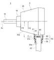
- a resin cover member 5 is attached to the outer peripheral surface 35a of the mold resin portion 35 so as to cover the lead wire 61 drawn from the mold resin portion 35.
- the cover member 5 is made of, for example, PBT or ABS (acrylonitrile butadiene styrene) resin.
- the cover member 5 is omitted in FIGS. 2 to 4.
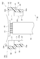
- FIG. 5 is a notched perspective view showing the cover member 5, the opening portion 45, and the lead wire 61.
- FIG. 6 is a side view of the electric motor 1, in which the cover member 5 is cut out in a plane parallel to the central axis Ax.
- FIG. 7 is a cross-sectional view orthogonal to the central axis Ax showing the cover member 5, the opening portion 45, and the lead wire 61.
- the cover member 5 has a box shape having an opening 5S on the mold resin portion 35 side. More specifically, the cover member 5 has a pair of first wall portions 51 (FIG. 6) facing in the axial direction, a pair of second wall portions 52 facing in the circumferential direction, and a side opposite to the opening 5S. It has a bottom 53 to be located. The wall portions 51 and 52 and the bottom portion 53 form a housing portion 50.
- the opening 5S of the cover member 5 is closed by the outer peripheral surface 35a of the mold resin portion 35.
- a hole 53a through which the tube 62 is passed is formed in the bottom portion 53.
- the wall portions 51 and 52 and the bottom portion 53 form a storage space for accommodating the lead wire 61 between the wall portions 51 and 52 and the outer peripheral surface 35a of the mold resin portion 35.
- the wall portions 51 and 52 of the cover member 5 are fitted to the mouth portion 45.
- the cover member 5 can be positioned with respect to the mold resin portion 35. Further, by fitting the cover member 5 to the mouthpiece portion 45, the cover member 5 can be attached to the mold resin portion 35 without using an adhesive.
- the hole 53a of the bottom 53 of the cover member 5 is a hole through which the tube 62 passes.
- the cross-sectional shape of the hole 53a is a shape corresponding to the outer circumference of the tube 62, for example, a circular shape. It is desirable that the inner peripheral surface of the hole 53a is in close contact with the outer peripheral surface of the tube 62.
- the first wall portion 51 has an end surface 51a facing the mold resin portion 35.
- the end surface 51a has a shape along the outer peripheral surface 35a of the mold resin portion 35.
- the second wall portion 52 has an end surface 52a facing the mold resin portion 35.
- the end surface 52a has a shape along the outer peripheral surface 35a of the mold resin portion 35.
- the resin constituting the cover member 5 has a lower elastic modulus than the resin constituting the mold resin portion 35. In other words, it is desirable that the cover member 5 is more easily elastically deformed than the mold resin portion 35. This relationship is established when the cover member 5 is made of PBT or ABS and the mold resin portion 35 is made of BMC.
- the cover member 5 when the cover member 5 is pressed against the outer peripheral surface 35a of the mold resin portion 35, the cover member 5 is elastically deformed along the outer peripheral surface 35a of the mold resin portion 35, so that the outer periphery of the cover member 5 and the mold resin portion 35 is deformed. Adhesion to the surface 35a can be improved.
- water particularly fine water vapor of molecules
- the expression "water” shall also include water vapor.
- the lead wire 61 drawn from the mold resin portion 35 is accommodated in the accommodation space formed by the outer peripheral surface 35a of the mold resin portion 35 and the cover member 5.
- the opening portion 45 exposed from the mold resin portion 35 is surrounded by the cover member 5. Therefore, it is possible to block the intrusion path of water into the motor 1 and prevent the motor 1 from malfunctioning.
- the motor 1 is attached to the installation portion of the outdoor unit 101 such as the frame 109 (FIG. 22 (B)) by the screw inserted into the mounting hole 39 of the leg portion 38. It is desirable that the lead wire 61 is pulled downward from the mold resin portion 35 with the electric motor 1 attached to the installation portion, and the outlet portion 45 and the cover member 5 are located below the mold resin portion 35.
- the cover member 5 is located inside the end surface 35b on the load side of the mold resin portion 35 by a distance A1 in the axial direction, and the end surface 35c on the unload side of the mold resin portion 35 is located inside. It is located inward by the distance A2 with respect to the distance A2. That is, the cover member 5 is located inside the mold resin portion 35 in the axial direction with respect to both end faces 35b and 35c in the axial direction.
- cover member 5 protrudes from the mold resin portion 35 in the axial direction, water may enter from the surface of the cover member 5 on the mold resin portion 35 side.
- the cover member 5 is located inside the axially end surfaces 35b and 35c of the mold resin portion 35, the mold resin portion 35 side of the cover member 5 is formed by the outer peripheral surface 35a of the mold resin portion 35. Since it is covered, it is possible to suppress the intrusion of water into the cover member 5.
- FIG. 8A is a schematic view showing the relationship between the end surface 51a of the first wall portion 51 of the first embodiment and the outer peripheral surface 35a of the mold resin portion 35.
- FIG. 8B is a schematic view showing the relationship between the end surface 51a of the first wall portion 51 and the outer peripheral surface 35a of the mold resin portion 35 in another configuration example.
- the outer peripheral surface 35a of the mold resin portion 35 is circular in a cross section orthogonal to the central axis Ax.
- the end surface 51a of the first wall portion 51 is formed in an arc shape that is concave on the mold resin portion 35 side. It is desirable that the radius of curvature r of the end surface 51a is equal to or less than the radius of curvature R of the outer peripheral surface 35a of the mold resin portion 35 (r ⁇ R).
- the end surface Gap S between the outer peripheral surface 35a of the mold resin portion 35 is formed on both sides of the 51a in the circumferential direction.
- the shape of the cover member 5 is not limited to the box shape shown in FIGS. ..
- the cover member 5 may have a cylindrical shape having an opening on the mold resin portion 35 side. Also in this case, the opening is closed by the outer peripheral surface 35a of the mold resin portion 35, and a hole for pulling out the lead wire 61 is provided at the bottom.
- the cover member 5 made of resin is attached to the mold resin portion 35 that covers the stator 30 and the circuit board 4, and the outer periphery of the cover member 5 and the mold resin portion 35 is attached.
- the lead wire 61 drawn from the mold resin portion 35 is accommodated in the accommodating space formed by the surface 35a.
- the cover member 5 has a hole portion 53a for pulling out the lead wire 61 from the accommodation space.
- the lead wire 61 drawn out from the mold resin portion 35 is accommodated in the accommodation space surrounded by the outer peripheral surface 35a of the mold resin portion 35 and the cover member 5, so that water intrudes into the motor 1. It is possible to block the path and suppress the intrusion of water into the motor 1. Thereby, the malfunction of the electric motor 1 can be suppressed.
- the cover member 5 has an arcuate end surface 51a facing the outer peripheral surface 35a of the mold resin portion 35, the radius of curvature r of the end surface 51a is equal to or less than the radius of curvature R of the outer peripheral surface 35a of the mold resin portion 35. (R ⁇ R), it is possible to prevent a gap from being formed on both sides of the cover member 5 in the circumferential direction. As a result, it is possible to suppress the intrusion of water into the motor 1.
- the cover member 5 is located inside the mold resin portion 35 in the axial direction with respect to both end faces 35b and 35c in the axial direction. Therefore, the opening of the cover member 5 can be sufficiently closed by the outer peripheral surface 35a of the mold resin portion 35, and the intrusion of water into the motor 1 can be effectively suppressed.
- the cover member 5 is made of a resin having a higher elastic modulus than the resin constituting the mold resin portion 35, the cover member 5 is pressed against the outer peripheral surface 35a of the mold resin portion 35 to improve the adhesion. It is possible to effectively suppress the intrusion of water into the electric motor 1.
- the cover member 5 since the cover member 5 fits into the opening portion 45, the cover member 5 can be positioned with respect to the mold resin portion 35. Since the expansion of the gap between the cover member 5 and the mold resin portion 35 due to the misalignment of the cover member 5 is prevented, the intrusion of water into the motor 1 can be effectively suppressed.
- the cover member 5 is located below the mold resin portion 35 with the motor 1 attached to the installation portion, the cover member 5 is located above the mold resin portion 35 as compared with the case where the cover member 5 is located above the mold resin portion 35. It is difficult for water to enter through the hole 53a of the member 5. Therefore, it is possible to effectively suppress the intrusion of water into the motor 1.
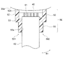
- FIG. 9 is a notched perspective view showing the cover member 5A, the opening portion 45, and the lead wire 61 of the second embodiment.
- FIG. 10 is a side view of the electric motor 1, in which the cover member 5A is cut out in a plane parallel to the central axis Ax.
- FIG. 11 is a cross-sectional view showing the cover member 5A, the opening portion 45, and the lead wire 61, which are orthogonal to the central axis Ax.
- the cover member 5A of the second embodiment has a tube surrounding portion 55 surrounding the tube 62 in addition to the housing portion 50 described in the first embodiment. That is, the cover member 5A has a two-stage structure of a housing portion 50 and a tube surrounding portion 55.
- the housing portion 50 and the tube surrounding portion 55 are integrally formed of the same material.
- the tube surrounding portion 55 is provided on the side opposite to the mold resin portion 35 with respect to the housing portion 50.
- the tube surrounding portion 55 extends in the drawing direction of the lead wire 61, that is, in the radial direction about the central axis Ax. It is desirable that the tube enclosing portion 55 extends downward from the bottom 53 with the motor 1 attached to the installation portion.
- the tube surrounding portion 55 has a hole portion 55a through which the tube 62 is passed.
- the hole portion 55a of the tube surrounding portion 55 surrounds the tube 62 drawn out from the hole portion 53a of the housing portion 50.
- the cross-sectional shape of the hole portion 55a is a shape that matches the outer circumference of the tube 62, for example, a circular shape. It is desirable that the inner peripheral surface of the hole portion 55a is in close contact with the outer peripheral surface of the tube 62.
- the wall portions 51 and 52 and the bottom portion 53 constitute the housing portion 50.
- the lead wire 61 drawn out from the outlet portion 45 is housed in a storage space surrounded by the outer peripheral surface 35a of the mold resin portion 35 and the housing portion 50.
- the tube enclosing portion 55 is smaller than the housing portion 50 in at least one of the circumferential dimension and the axial dimension, more preferably both. With this configuration, the cover member 5A can be miniaturized as a whole.
- the tube surrounding portion 55 has a prismatic shape, but may have another shape, for example, a cylindrical shape. That is, the tube surrounding portion 55 may have a hole portion 55a into which the tube 62 is inserted.
- the electric motor of the second embodiment is configured in the same manner as the electric motor 1 of the first embodiment except for the above-mentioned points.
- the cover member 5A has a tube surrounding portion 55 that covers the tube 62. Therefore, it becomes difficult for water to enter the cover member 5A, and as a result, the intrusion of water into the motor 1 can be effectively suppressed.
- FIG. 12 is a cross-sectional view showing the cover member 5B, the opening portion 45, and the lead wire 61 of the third embodiment, which are orthogonal to the central axis Ax.
- the cover member 5B has a tapered portion 54 on the tube surrounding portion 55 side of the housing portion 50.
- the tapered portion 54 is formed on the tube surrounding portion 55 side with respect to the opening portion 45.
- Each of the tapered portions 54 of the pair of second wall portions 52 is inclined so that the distance between them is wide on the side of the opening portion 45 and narrowed on the side of the tube surrounding portion 55.
- FIG. 12 shows the tapered portion 54 of the second wall portion 52
- the tapered portion 54 may be provided on the wall portion 51
- the tapered portion 54 may be provided on both the first wall portion 51 and the second wall portion 52. It may be provided.
- the electric motor of the third embodiment is configured in the same manner as the electric motor 1 of the second embodiment except for the above-mentioned points.
- the cover member 5B has the tapered portion 54, the amount of the resin forming the cover member 5B is reduced, and the manufacturing cost is reduced. Can be reduced.
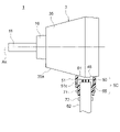
- FIG. 13 is a side view of the motor 1 of the fourth embodiment, and shows the cover member 5C cut out in a plane parallel to the central axis Ax.
- the cover member 5C of the fourth embodiment has a through hole 51c in the first wall portion 51.
- the through hole 51c is a discharge port for discharging the water to the outside of the cover member 5C when the water collects in the cover member 5C.
- the size of the through hole 51c may be a size that allows water to pass through.
- the shortest distance H1 from the central axis Ax to the through hole 51c is longer than the longest distance H2 from the central axis Ax to the opening portion 45. That is, with the motor 1 attached to the installation portion, the through hole 51c of the cover member 5C is located at a position lower than that of the mouth opening portion 45.
- the through hole 51c extends parallel to the central axis Ax. That is, the through hole 51c extends in the horizontal direction with the motor 1 attached to the installation portion. Therefore, it is possible to prevent water vapor rising from the lower side of the motor 1 from entering the cover member 5C through the through hole 51c.
- through holes 51c are formed in both of the pair of first wall portions 51, but through holes 51c may be formed only in one of the first wall portions 51. Further, a through hole may be formed in the second wall portion 52 instead of the first wall portion 51. That is, it suffices if a through hole for draining water is formed in at least one place of the housing portion 50.
- the cover member 5C shown in FIG. 13 has the tube surrounding portion 55 described in the second embodiment, but does not have to have the tube surrounding portion 55. Further, the cover member 5C may have the tapered portion 54 described in the third embodiment.
- the electric motor of the fourth embodiment is configured in the same manner as the electric motor 1 of the first embodiment except for the above-mentioned points.
- the cover member 5C since the cover member 5C has a through hole 51c at at least one place of the housing portion 50, when water collects in the cover member 5C, the water is passed through the through hole. It can be discharged from 51c. As a result, the intrusion of water into the motor 1 can be effectively suppressed.
- the through hole 51c of the cover member 5C is located at a position lower than the outlet portion 45 when the motor 1 is attached to the installation portion, the water in the cover member 5C reaches the height of the outlet portion 45. It can be discharged from the through hole 51c before. As a result, the intrusion of water into the motor 1 can be effectively suppressed.
- FIG. 14A is a side view of the motor 1 of the fifth embodiment, and shows the cover member 5C and the fastening member 71 cut out in a plane parallel to the central axis Ax.
- the fastening member 71 is provided so as to surround the tube surrounding portion 55 of the cover member 5C.
- FIG. 14B is a perspective view showing the fastening member 71.
- the fastening member 71 is a binding band made of resin. More specifically, the fastening member 71 is an insulator (registered trademark) made of nylon.
- the fastening member 71 can fasten the tube surrounding portion 55, the tube 62 inside the tube enclosing portion 55, and the lead wire 61 inside the tube at one time.
- FIG. 15 is a diagram showing another configuration example of the fifth embodiment.
- the fastening member 72 is provided below the cover member 5C, that is, on the side opposite to the mold resin portion 35 with respect to the cover member 5C so as to surround the tube 62.
- the structure of the fastening member 72 is the same as that of the fastening member 71 shown in FIG. 14 (B).
- the tube 62 and the lead wire 61 inside the tube 62 are tightened by the fastening member 72. Since the fastening member 72 is fixed to the tube 62, the cover member 5C can be positioned between the fastening member 71 and the mold resin portion 35 in the lead wire 61 drawing direction.
- the tightening force of the fastening member 72 may be smaller than the tightening force of the fastening member 71 shown in FIG. 14 (A).
- FIG. 16 is a diagram showing still another configuration example of the fifth embodiment.
- the fastening member 71 is provided so as to surround the tube surrounding portion 55
- the fastening member 72 is provided so as to surround the tube 62.
- the configurations of the fastening members 71 and 72 are as described above.
- the tube surrounding portion 55, the tube 62, and the lead wire 61 are fastened by the fastening member 71, and the tube 62 and the lead wire 61 are fastened by the fastening member 72.
- the fastening member 71 suppresses the intrusion of water into the cover member 5C from the gap between the tube surrounding portion 55 and the tube 62.
- the fastening member 72 can position the cover member 5C in the drawing direction of the lead wire 61.
- the electric motor of the fifth embodiment is configured in the same manner as the electric motor 1 of the first embodiment except for the above-mentioned points.
- the fastening member 71 surrounding the tube surrounding portion 55
- water can be suppressed from entering the cover member 5C through the gap between the tube surrounding portion 55 and the tube 62. Can be done.
- the fastening member 72 surrounding the tube 62 on the opposite side of the cover member 5C from the mold resin portion 35 the cover member 5C can be positioned in the lead wire 61 drawing direction.
- FIG. 17 is a cross-sectional view showing the cover member 5A, the tubular member 81, the opening portion 45, and the lead wire 61 of the sixth embodiment, orthogonal to the central axis Ax.
- the tubular member 81 is provided so as to cover the tube surrounding portion 55 and the tube 62 of the cover member 5A.
- the tubular member 81 is made of a heat-shrinkable resin.
- the heat-shrinkable resin is, for example, a fluororesin, vinyl chloride, silicone rubber, or polyolefin.
- the tubular member 81 covers the tube surrounding portion 55 of the cover member 5A and also covers the tube 62 drawn out from the tube surrounding portion 55.
- the tube surrounding portion 55 and the tube 62 are in close contact with each other by being covered with the tubular member 81, it is possible to suppress the intrusion of water into the cover member 5A through the gap between the tube surrounding portion 55 and the tube 62. Further, by tightening the tube surrounding portion 55 with the tubular member 81, the cover member 5A can be positioned in the pull-out direction of the lead wire 61.
- FIG. 17 shows the cover member 5A described in the second embodiment
- any of the cover members 5B and 5C described in the third and fourth embodiments may be used instead of the cover member 5A.
- the fastening members 71 and 72 described in the fifth embodiment may be added.
- the electric motor of the sixth embodiment is configured in the same manner as the electric motor 1 of the first embodiment except for the above-mentioned points.
- the tubular member 81 covers the tube surrounding portion 55 and the tube 62, water is suppressed from entering the cover member 5A through the gap between the tube surrounding portion 55 and the tube 62. be able to. As a result, the intrusion of water into the motor 1 can be effectively suppressed.
- FIG. 18 is a cross-sectional view showing the cover member 5D, the opening portion 45, and the lead wire 61 of the seventh embodiment, which are orthogonal to the central axis Ax.
- the housing portion 50 and the tube surrounding portion 55 are integrally formed of the same material.
- the housing portion 50 and the tube surrounding portion 56 are made of different materials.
- the tube surrounding portion 56 of the seventh embodiment is made of a heat-shrinkable resin.
- the heat-shrinkable resin is, for example, a fluororesin, vinyl chloride, silicone rubber, or polyolefin.
- the tube enclosing portion 56 has a hole portion 56a through which the tube 62 is passed.
- the cross-sectional shape of the hole portion 56a is a shape that matches the outer circumference of the tube 62, for example, a circular shape.
- the tube surrounding portion 56 and the tube 62 are in close contact with each other, the intrusion of water into the cover member 5D from the gap between the tube surrounding portion 56 and the tube 62 is suppressed. Further, since the tube surrounding portion 56 is pressed against the tube 62, the cover member 5D can be positioned in the lead wire 61 drawing direction.
- the cover member 5D of FIG. 18 may be provided with the tapered portion 54 described in the third embodiment, or may be provided with the through hole 51c described in the fourth embodiment. Further, the fastening members 71 and 72 described in the fifth embodiment or the tubular member 81 described in the sixth embodiment may be added.
- the electric motor of the seventh embodiment is configured in the same manner as the electric motor 1 of the first embodiment except for the above-mentioned points.
- the tube surrounding portion 56 of the cover member 5D is formed of the heat-shrinkable resin, the tube surrounding portion 56 and the tube 62 are brought into close contact with each other and covered from these gaps. It is possible to suppress the intrusion of water into the member 5D. As a result, the intrusion of water into the motor 1 can be effectively suppressed.
- FIG. 19 is a cross-sectional view showing a state in which the cover member 5E of the eighth embodiment is divided together with the opening portion 45 and the lead wire 61.
- the cover member 5E of the eighth embodiment is divided into two components 501 and 502 by a dividing surface 57.
- the split surface 57 is a surface parallel to the pull-out direction of the lead wire 61, and is a surface that passes through the accommodation space in the housing portion 50 and the hole portion 55a of the tube surrounding portion 55. Further, it is desirable that the divided surface 57 passes through the center of the accommodation space in the housing portion 50 and the center of the hole portion 55a of the tube surrounding portion 55.
- a recess 57a is formed on the divided surface 57 of the component portion 501.
- a convex portion 57b that fits into the concave portion 57a of the constituent portion 501 is formed on the divided surface 57 of the constituent portion 502.
- the constituent portions 501 and 502 With the divided surfaces 57 of the constituent portions 501 and 502 in close contact with each other, the constituent portions 501 and 502 are fixed to each other by fitting the concave portion 57a and the convex portion 57b.
- the concave portion 57a and the convex portion 57b are formed in the tube surrounding portion 55 in FIG. 19, they may be formed in the housing portion 50, and may be formed in both the tube surrounding portion 55 and the housing portion 50. May be good.
- FIG. 20 is a cross-sectional view showing a cover member 5E in which constituent portions 501 and 502 are combined together with a mouth portion 45 and a lead wire 61.
- the components 501 and 502 are combined so as to sandwich the lead wire 61 and the tube 62 in between.
- the cover member 5E can be obtained.
- the lead wire 61 is housed in the housing portion 50, and the outer peripheral surface of the tube 62 comes into contact with the inner peripheral surface of the hole portion 55a of the tube surrounding portion 55. Further, the inner surfaces 51b and 52b of the housing portion 50 are fitted to the opening portion 45.
- the housing portion 50 and the tube surrounding portion 55 are configured in the same manner as the housing portion 50 and the tube surrounding portion 55 described in the second embodiment, except that the housing portion 50 and the tube surrounding portion 55 are each divided by the divided surface 57.
- the cover member 5E is configured by assembling the constituent parts 501 and 502, the cover member 5E can be easily attached to the lead wire 61 lead-out portion.
- the cover member 5E is divided into two in the circumferential direction about the central axis Ax here, it may be divided into two in the direction of the central axis Ax, that is, in the axial direction. Further, the cover member 5E may be composed of a combination of three or more constituent parts.
- the cover member 5E may be provided with the tapered portion 54 described in the third embodiment, or may be provided with the through hole 51c described in the fourth embodiment. Further, the fastening members 71 and 72 described in the fifth embodiment, the tubular member 81 described in the sixth embodiment, or the tube surrounding portion 56 of the seventh embodiment may be provided. Further, the cover member 5 of the first embodiment may be configured by a combination of a plurality of constituent parts.
- the electric motor of the seventh embodiment is configured in the same manner as the electric motor 1 of the first embodiment except for the above-mentioned points.
- the cover member 5E is configured by combining the constituent portions 501 and 502, the cover member 5E can be easily attached to the mold resin portion 35.
- FIG. 21 is a perspective view showing a state in which the cover member 5F of the modified example of the eighth embodiment is divided.
- the cover member 5F is divided into two constituent portions 501 and 502 by a dividing surface 57, and the constituent portions 501 and 502 are connected to each other by a deformable connecting portion 58.
- the connecting portion 58 is an elastically deformable thin-walled portion formed between the constituent portions 501 and 502.
- the connecting portion 58 extends along one side of the divided surface 57 in the housing portion 50 in parallel with the drawing direction of the lead wire 61.
- the connecting portion 58 is not limited to the thin-walled portion, and may be, for example, a hinge.
- the components 501 and 502 are combined so as to sandwich the lead wire 61 and the tube 62 while deforming the connecting portion 58.
- the cover member 5F can be obtained.
- the constituent parts 501 and 502 of the cover member 5F are connected by the connecting portion 58, and the cover member 5F can be handled as one component when attached to the mold resin portion 35. Therefore, the cover member 5F can be more easily attached to the mold resin portion 35.
- FIG. 22A is a diagram showing the configuration of the air conditioner 100.
- the air conditioner 100 includes an outdoor unit 101, an indoor unit 102, and a refrigerant pipe 103 connecting them.
- the outdoor unit 101 includes, for example, an outdoor blower 110 which is a propeller fan
- the indoor unit 102 includes an indoor blower 120 which is, for example, a cross-flow fan.
- the outdoor blower 110 has an impeller 105 and an electric motor 1 for driving the impeller 105.
- the indoor blower 120 has an impeller 121 and an electric motor 1 for driving the impeller 121.
- FIG. 22A also shows a compressor 104 that compresses the refrigerant.
- FIG. 22B is a cross-sectional view of the outdoor unit 101.
- the electric motor 1 is supported by a frame 109 arranged in the housing 108 of the outdoor unit 101.
- An impeller 105 is attached to the shaft 11 of the electric motor 1 via a hub 106.
- the impeller 105 rotates due to the rotation of the electric motor 1, and blows air to the outside.
- heat is released when the refrigerant compressed by the compressor 104 is condensed in the condenser, and this heat is released to the outside by the air blown by the outdoor blower 110.
- the impeller 121 is rotated by the rotation of the electric motor 1 to blow air into the room.
- the air conditioner 100 when the refrigerant evaporates in the evaporator, the heat of the air is taken away, and the air is blown into the room by the blower of the indoor blower 120.
- the motor 1 of each of the above-described embodiments and modifications has improved operational stability due to the suppression of water intrusion. Therefore, the reliability of the air conditioner 100 can be improved by using the motor 1 as the drive source of the blowers 110 and 120 of the air conditioner 100.
- the motor 1 is used as the drive source of the outdoor blower 110 and the drive source of the indoor blower 120, the motor 1 may be used as at least one of the drive sources.
- the electric motor 1 described in each embodiment and modification can be mounted on an electric device other than the blower of the air conditioner.
Landscapes
- Engineering & Computer Science (AREA)
- Power Engineering (AREA)
- Mechanical Engineering (AREA)
- General Engineering & Computer Science (AREA)
- Motor Or Generator Frames (AREA)
Priority Applications (4)
| Application Number | Priority Date | Filing Date | Title |
|---|---|---|---|
| CN202080105934.5A CN116250166A (zh) | 2020-10-14 | 2020-10-14 | 电动机、送风机以及空调装置 |
| US18/245,648 US20230358243A1 (en) | 2020-10-14 | 2020-10-14 | Motor, fan, and air conditioner |
| JP2022556758A JP7463046B2 (ja) | 2020-10-14 | 2020-10-14 | 電動機、送風機および空気調和装置 |
| PCT/JP2020/038795 WO2022079837A1 (ja) | 2020-10-14 | 2020-10-14 | 電動機、送風機および空気調和装置 |
Applications Claiming Priority (1)
| Application Number | Priority Date | Filing Date | Title |
|---|---|---|---|
| PCT/JP2020/038795 WO2022079837A1 (ja) | 2020-10-14 | 2020-10-14 | 電動機、送風機および空気調和装置 |
Publications (1)
| Publication Number | Publication Date |
|---|---|
| WO2022079837A1 true WO2022079837A1 (ja) | 2022-04-21 |
Family
ID=81208955
Family Applications (1)
| Application Number | Title | Priority Date | Filing Date |
|---|---|---|---|
| PCT/JP2020/038795 Ceased WO2022079837A1 (ja) | 2020-10-14 | 2020-10-14 | 電動機、送風機および空気調和装置 |
Country Status (4)
| Country | Link |
|---|---|
| US (1) | US20230358243A1 (https=) |
| JP (1) | JP7463046B2 (https=) |
| CN (1) | CN116250166A (https=) |
| WO (1) | WO2022079837A1 (https=) |
Cited By (1)
| Publication number | Priority date | Publication date | Assignee | Title |
|---|---|---|---|---|
| WO2023233609A1 (ja) * | 2022-06-02 | 2023-12-07 | 三菱電機株式会社 | 電動機及び空気調和機 |
Citations (4)
| Publication number | Priority date | Publication date | Assignee | Title |
|---|---|---|---|---|
| JPS6042055U (ja) * | 1983-08-29 | 1985-03-25 | 株式会社東芝 | モ−タのリ−ド線導出構造 |
| JPH0736566U (ja) * | 1993-12-09 | 1995-07-04 | マブチモーター株式会社 | 小型モータ |
| JP2014039421A (ja) * | 2012-08-20 | 2014-02-27 | Mitsubishi Electric Corp | モールド電動機及び空気調和機 |
| JP2015154645A (ja) * | 2014-02-17 | 2015-08-24 | 三菱電機株式会社 | 電動機、空気調和機、ヒートポンプ式給湯システム及びヒートポンプ式床暖房システム |
Family Cites Families (2)
| Publication number | Priority date | Publication date | Assignee | Title |
|---|---|---|---|---|
| JPH08140299A (ja) * | 1994-11-07 | 1996-05-31 | Daikin Ind Ltd | 直流ブラシレスモータ |
| JP3811415B2 (ja) | 2002-03-18 | 2006-08-23 | アスモ株式会社 | 直流モータ |
-
2020
- 2020-10-14 WO PCT/JP2020/038795 patent/WO2022079837A1/ja not_active Ceased
- 2020-10-14 US US18/245,648 patent/US20230358243A1/en not_active Abandoned
- 2020-10-14 CN CN202080105934.5A patent/CN116250166A/zh active Pending
- 2020-10-14 JP JP2022556758A patent/JP7463046B2/ja active Active
Patent Citations (4)
| Publication number | Priority date | Publication date | Assignee | Title |
|---|---|---|---|---|
| JPS6042055U (ja) * | 1983-08-29 | 1985-03-25 | 株式会社東芝 | モ−タのリ−ド線導出構造 |
| JPH0736566U (ja) * | 1993-12-09 | 1995-07-04 | マブチモーター株式会社 | 小型モータ |
| JP2014039421A (ja) * | 2012-08-20 | 2014-02-27 | Mitsubishi Electric Corp | モールド電動機及び空気調和機 |
| JP2015154645A (ja) * | 2014-02-17 | 2015-08-24 | 三菱電機株式会社 | 電動機、空気調和機、ヒートポンプ式給湯システム及びヒートポンプ式床暖房システム |
Cited By (1)
| Publication number | Priority date | Publication date | Assignee | Title |
|---|---|---|---|---|
| WO2023233609A1 (ja) * | 2022-06-02 | 2023-12-07 | 三菱電機株式会社 | 電動機及び空気調和機 |
Also Published As
| Publication number | Publication date |
|---|---|
| US20230358243A1 (en) | 2023-11-09 |
| JPWO2022079837A1 (https=) | 2022-04-21 |
| CN116250166A (zh) | 2023-06-09 |
| JP7463046B2 (ja) | 2024-04-08 |
Similar Documents
| Publication | Publication Date | Title |
|---|---|---|
| JP6726630B2 (ja) | 空調用ブロアモータユニット | |
| US20170040864A1 (en) | Electric Compressor | |
| US11962229B2 (en) | Motor, fan, air conditioner, and manufacturing method of motor | |
| CN107645224A (zh) | 用于空气调节器的鼓风机马达单元 | |
| JP7337249B2 (ja) | 送風機および空気調和装置 | |
| JP7463046B2 (ja) | 電動機、送風機および空気調和装置 | |
| AU2020431615B2 (en) | Motor, fan, and air conditioner | |
| WO2022249307A1 (ja) | 電動機及び空気調和機 | |
| JPH09308207A (ja) | ブラシレス電動機 | |
| US20220352780A1 (en) | Motor, fan, air conditioner, and manufacturing method of motor | |
| US20250219480A1 (en) | Electric motor and air conditioner | |
| WO2020213601A1 (ja) | モータ、送風機、空気調和装置およびモータの製造方法 | |
| AU2019459440B2 (en) | Electric motor, fan, air conditioning device, and method for manufacturing electric motor | |
| WO2023095316A1 (ja) | 電動機及び空気調和機 | |
| JP5931488B2 (ja) | 電動圧縮機 | |
| US12372095B2 (en) | Centrifugal blower | |
| JPH07123674A (ja) | 空調機のファン用電動機 | |
| JPH11182488A (ja) | 送風機 | |
| WO2023233609A1 (ja) | 電動機及び空気調和機 | |
| JPH07143705A (ja) | ファン一体化電動機 | |
| WO2025154247A1 (ja) | モータユニット、送風機および空気調和装置 | |
| WO2025126435A1 (ja) | モータユニット、送風機および空気調和装置 | |
| WO2022180708A1 (ja) | ステータ、電動機、及び空気調和機 | |
| JP2002058229A (ja) | 永久磁石型ブラシレス電動機とそれを用いたエアコン装置 |
Legal Events
| Date | Code | Title | Description |
|---|---|---|---|
| 121 | Ep: the epo has been informed by wipo that ep was designated in this application |
Ref document number: 20957666 Country of ref document: EP Kind code of ref document: A1 |
|
| ENP | Entry into the national phase |
Ref document number: 2022556758 Country of ref document: JP Kind code of ref document: A |
|
| NENP | Non-entry into the national phase |
Ref country code: DE |
|
| 122 | Ep: pct application non-entry in european phase |
Ref document number: 20957666 Country of ref document: EP Kind code of ref document: A1 |