WO2022074755A1 - Échangeur d'outil automatique - Google Patents
Échangeur d'outil automatique Download PDFInfo
- Publication number
- WO2022074755A1 WO2022074755A1 PCT/JP2020/037968 JP2020037968W WO2022074755A1 WO 2022074755 A1 WO2022074755 A1 WO 2022074755A1 JP 2020037968 W JP2020037968 W JP 2020037968W WO 2022074755 A1 WO2022074755 A1 WO 2022074755A1
- Authority
- WO
- WIPO (PCT)
- Prior art keywords
- tool
- automatic
- machine
- changer
- spindle
- Prior art date
Links
- 238000012545 processing Methods 0.000 claims abstract description 29
- 230000008859 change Effects 0.000 claims description 55
- 238000003754 machining Methods 0.000 claims description 46
- 210000000078 claw Anatomy 0.000 claims description 35
- 230000033001 locomotion Effects 0.000 claims description 32
- 230000007246 mechanism Effects 0.000 claims description 21
- 238000003825 pressing Methods 0.000 claims description 8
- 238000001514 detection method Methods 0.000 claims description 7
- 238000006073 displacement reaction Methods 0.000 claims description 7
- 238000003860 storage Methods 0.000 claims description 5
- 238000000034 method Methods 0.000 claims description 4
- 230000008569 process Effects 0.000 claims description 4
- 238000005192 partition Methods 0.000 claims description 2
- 230000003028 elevating effect Effects 0.000 description 23
- 238000006243 chemical reaction Methods 0.000 description 21
- 238000012546 transfer Methods 0.000 description 10
- 238000005520 cutting process Methods 0.000 description 6
- 150000001875 compounds Chemical class 0.000 description 4
- 238000000926 separation method Methods 0.000 description 4
- 230000001174 ascending effect Effects 0.000 description 3
- 230000008602 contraction Effects 0.000 description 3
- 239000002826 coolant Substances 0.000 description 3
- 238000013459 approach Methods 0.000 description 2
- 239000002131 composite material Substances 0.000 description 2
- 240000007594 Oryza sativa Species 0.000 description 1
- 235000007164 Oryza sativa Nutrition 0.000 description 1
- 230000005540 biological transmission Effects 0.000 description 1
- 239000003638 chemical reducing agent Substances 0.000 description 1
- 238000005553 drilling Methods 0.000 description 1
- 230000000694 effects Effects 0.000 description 1
- 239000011521 glass Substances 0.000 description 1
- 239000000463 material Substances 0.000 description 1
- 238000012986 modification Methods 0.000 description 1
- 230000004048 modification Effects 0.000 description 1
- 230000002093 peripheral effect Effects 0.000 description 1
- 235000009566 rice Nutrition 0.000 description 1
Images


Classifications
-
- B—PERFORMING OPERATIONS; TRANSPORTING
- B23—MACHINE TOOLS; METAL-WORKING NOT OTHERWISE PROVIDED FOR
- B23Q—DETAILS, COMPONENTS, OR ACCESSORIES FOR MACHINE TOOLS, e.g. ARRANGEMENTS FOR COPYING OR CONTROLLING; MACHINE TOOLS IN GENERAL CHARACTERISED BY THE CONSTRUCTION OF PARTICULAR DETAILS OR COMPONENTS; COMBINATIONS OR ASSOCIATIONS OF METAL-WORKING MACHINES, NOT DIRECTED TO A PARTICULAR RESULT
- B23Q3/00—Devices holding, supporting, or positioning work or tools, of a kind normally removable from the machine
- B23Q3/155—Arrangements for automatic insertion or removal of tools, e.g. combined with manual handling
- B23Q3/157—Arrangements for automatic insertion or removal of tools, e.g. combined with manual handling of rotary tools
- B23Q3/15773—Arrangements for automatic insertion or removal of tools, e.g. combined with manual handling of rotary tools a transfer device taking the tool from a storage device and passing it on to other transfer devices, which insert it in a spindle
-
- B—PERFORMING OPERATIONS; TRANSPORTING
- B23—MACHINE TOOLS; METAL-WORKING NOT OTHERWISE PROVIDED FOR
- B23Q—DETAILS, COMPONENTS, OR ACCESSORIES FOR MACHINE TOOLS, e.g. ARRANGEMENTS FOR COPYING OR CONTROLLING; MACHINE TOOLS IN GENERAL CHARACTERISED BY THE CONSTRUCTION OF PARTICULAR DETAILS OR COMPONENTS; COMBINATIONS OR ASSOCIATIONS OF METAL-WORKING MACHINES, NOT DIRECTED TO A PARTICULAR RESULT
- B23Q3/00—Devices holding, supporting, or positioning work or tools, of a kind normally removable from the machine
- B23Q3/155—Arrangements for automatic insertion or removal of tools, e.g. combined with manual handling
- B23Q3/157—Arrangements for automatic insertion or removal of tools, e.g. combined with manual handling of rotary tools
- B23Q3/15713—Arrangements for automatic insertion or removal of tools, e.g. combined with manual handling of rotary tools a transfer device taking a single tool from a storage device and inserting it in a spindle
-
- B—PERFORMING OPERATIONS; TRANSPORTING
- B23—MACHINE TOOLS; METAL-WORKING NOT OTHERWISE PROVIDED FOR
- B23B—TURNING; BORING
- B23B11/00—Automatic or semi-automatic turning-machines incorporating equipment for performing other working procedures, e.g. slotting, milling, rolling
-
- B—PERFORMING OPERATIONS; TRANSPORTING
- B23—MACHINE TOOLS; METAL-WORKING NOT OTHERWISE PROVIDED FOR
- B23P—METAL-WORKING NOT OTHERWISE PROVIDED FOR; COMBINED OPERATIONS; UNIVERSAL MACHINE TOOLS
- B23P23/00—Machines or arrangements of machines for performing specified combinations of different metal-working operations not covered by a single other subclass
- B23P23/02—Machine tools for performing different machining operations
-
- B—PERFORMING OPERATIONS; TRANSPORTING
- B23—MACHINE TOOLS; METAL-WORKING NOT OTHERWISE PROVIDED FOR
- B23Q—DETAILS, COMPONENTS, OR ACCESSORIES FOR MACHINE TOOLS, e.g. ARRANGEMENTS FOR COPYING OR CONTROLLING; MACHINE TOOLS IN GENERAL CHARACTERISED BY THE CONSTRUCTION OF PARTICULAR DETAILS OR COMPONENTS; COMBINATIONS OR ASSOCIATIONS OF METAL-WORKING MACHINES, NOT DIRECTED TO A PARTICULAR RESULT
- B23Q3/00—Devices holding, supporting, or positioning work or tools, of a kind normally removable from the machine
- B23Q3/155—Arrangements for automatic insertion or removal of tools, e.g. combined with manual handling
- B23Q3/1552—Arrangements for automatic insertion or removal of tools, e.g. combined with manual handling parts of devices for automatically inserting or removing tools
- B23Q3/15526—Storage devices; Drive mechanisms therefor
- B23Q2003/15528—Storage devices; Drive mechanisms therefor the storage device including means to project tools therefrom, e.g. for transferring them
- B23Q2003/1553—Storage devices; Drive mechanisms therefor the storage device including means to project tools therefrom, e.g. for transferring them by rectilinear projection
-
- B—PERFORMING OPERATIONS; TRANSPORTING
- B23—MACHINE TOOLS; METAL-WORKING NOT OTHERWISE PROVIDED FOR
- B23Q—DETAILS, COMPONENTS, OR ACCESSORIES FOR MACHINE TOOLS, e.g. ARRANGEMENTS FOR COPYING OR CONTROLLING; MACHINE TOOLS IN GENERAL CHARACTERISED BY THE CONSTRUCTION OF PARTICULAR DETAILS OR COMPONENTS; COMBINATIONS OR ASSOCIATIONS OF METAL-WORKING MACHINES, NOT DIRECTED TO A PARTICULAR RESULT
- B23Q3/00—Devices holding, supporting, or positioning work or tools, of a kind normally removable from the machine
- B23Q3/155—Arrangements for automatic insertion or removal of tools, e.g. combined with manual handling
- B23Q3/1552—Arrangements for automatic insertion or removal of tools, e.g. combined with manual handling parts of devices for automatically inserting or removing tools
- B23Q3/1554—Transfer mechanisms, e.g. tool gripping arms; Drive mechanisms therefore
- B23Q2003/155414—Transfer mechanisms, e.g. tool gripping arms; Drive mechanisms therefore the transfer mechanism comprising two or more grippers
- B23Q2003/155425—Transfer mechanisms, e.g. tool gripping arms; Drive mechanisms therefore the transfer mechanism comprising two or more grippers pivotable
- B23Q2003/155428—Transfer mechanisms, e.g. tool gripping arms; Drive mechanisms therefore the transfer mechanism comprising two or more grippers pivotable about a common axis
Definitions
- the present invention relates to an automatic tool changer suitable for saving space in a multi-tasking machine.
- Patent Document 1 discloses a composite NC lathe (composite processing machine) that enables machining such as a machining center.
- This multi-tasking machine is an opposed biaxial lathe with a tool spindle capable of exchanging tools and a tool turret equipped with multiple exchange tools, and efficiently processes workpieces of various shapes from materials to finished products on the same machine. It is designed to be processed well. Specifically, it has a left main shaft and a right main shaft facing each other on the same axis, and a left turret turret turret and a right turret turret are arranged on the lower front side of both main shafts, and further, the back of both main shafts. A third turret is provided above the side.
- the conventional multi-tasking machine includes a tool magazine accommodating a plurality of tools used for the third turret, and an automatic tool changing device for exchanging the tools between the turrets. It is provided.
- the multi-tasking machine mentioned as a conventional example a plurality of tools are attached to the tool post of the tool turret arranged on the left and right in the circumferential direction, and various machining on the work is possible by swivel indexing.
- the third tool post is also provided with a tool magazine so as to be able to cope with various machining, and various tools that can be replaced with respect to the tool spindle are stored. Then, the tool is replaced with respect to the third tool post by an automatic tool changing device.
- the automatic tool changer is installed on the bed together with each device such as the turret tool post, the arrangement and configuration of the multi-tasking machine can be installed in a small space. rice field.
- an automatic tool changer is also mounted on a bed provided with left and right spindles, a turret tool post, etc., and is arranged at the left back of the bed. Therefore, in order to exchange tools for the third tool post, a structure is provided on the bed on which each device is arranged to move the tool table to the automatic tool change device, and the multi-tasking machine becomes larger by that amount. It has been done. Therefore, the conventional automatic tool changer is not suitable for realizing the space saving of the multi-tasking machine.
- an object of the present invention is to provide an automatic tool changer suitable for space saving of a multi-tasking machine in order to solve such a problem.
- the automatic tool changer according to one aspect of the present invention is provided in a multi-tasking machine in which the tool spindle device is arranged in the center of the opposed biaxial lathe, and is arranged in the upper part of the front surface of the machine body of the multi-axis machine.
- a tool magazine containing a plurality of tools for replacement with respect to the tool spindle device, a shift device for moving a tool between the tool magazine and the tool exchange position with respect to the tool spindle device, and the shift device and the tool spindle device.
- the shift device moves the tool between the tool magazine arranged on the upper front surface of the multi-tasking machine and the tool exchange position with respect to the tool spindle device, and the tool changer moves the tool with the tool spindle device. It is not necessary to move the tool spindle device as in the past, and the tool changer is arranged using the space above the front surface of the multi-tasking machine, so that the tool is moved by the shift device or tool changer. Therefore, it can be used as an automatic tool changer suitable for saving space in a multi-tasking machine.
- FIG. 2 is a perspective view, a front view, a plan view and a side view showing the main structure of the multi-tasking machine of the present embodiment.
- the multi-tasking machine 1 includes a first work spindle device 3 and a second work spindle device 4 that give rotation to the gripped work W, and a first turret device 5 and a second turret device 5 having a plurality of tools T corresponding to machining of the work W.
- the turret devices 6 are arranged symmetrically.
- the first work spindle device 3 and the second work spindle device 4 are coaxially arranged so that the chuck mechanisms 101 face each other, and each of them is provided with a first turret device 5 and a second turret device 6 which are blade bases. Has been done.
- a tool spindle device 2 for performing machining difficult with the lathe is provided in the center of the machine body.
- the first work spindle device 3, the second work spindle device 4, the first turret device 5, the second turret device 6, and the tool spindle device 2 are mounted on one base 7.
- Each device is assembled via a drive device so that it can move in a predetermined direction on the base 7.
- the moving direction (moving axis) of each device is defined and described as follows. First, the first work spindle device 3 and the second work spindle device 4 are designed so that the center line of the spindle is in the width direction of the machine body and is horizontal, and the moving direction is parallel to the spindle. , This is the Z axis.
- the first and second turret devices 5 and 6 and the tool spindle device 2 both move in the front-rear direction of the machine body orthogonal to the main axis and in the vertical direction of the machine body.
- the base 7 of the multi-tasking machine 1 is a so-called slant bed type, and the tool spindle device 2 is horizontal when moving in the front-rear direction of the machine, while the first and second turret devices 5 and 6 are inclined. There is. Therefore, the horizontal front-rear direction of the machine, which is the moving direction of the tool spindle device 2, is defined as the Y-axis, and the vertical vertical direction of the machine perpendicular to the Y-axis is defined as the X-axis.
- the tool spindle device 2 has its rotation axis parallel to the Y axis as the B axis.
- the first and second turret devices 5 and 6 have the Y-axis and the X-axis tilted by 45 degrees as the moving axes, which are the YL axis and the XL axis, respectively.
- the mounting surfaces of the first and second work spindle devices 3 and 4 arranged on the front side of the machine body are inclined so as to lower the front side, and conversely, the first first placed on the rear side of the machine body.
- the mounting surface of the second turret devices 5 and 6 is inclined so as to lower the rear.
- the front-rear inclination of the base 7 is formed so that the rear side of the machine body is larger so that the positions of the mounting surfaces of the first and second turret devices 5 and 6 are higher than the mounting surfaces of the first and second work spindle devices 3 and 4.
- the multi-tasking machine 1 of the present embodiment has a structure in which the dimensions in the front-rear direction of the machine body are suppressed by inclining the mounting surface of the base 7 in the front-rear direction.
- the first and second work spindle devices 3 and 4 (hereinafter referred to as work spindle devices 3 and 4 in the case of a description common to both devices) are configured in the same manner, and a chuck that grips and releases the work W to be machined.
- a mechanism 101 is provided. That is, in the work spindle devices 3 and 4, the spindle is rotatably incorporated into the cylindrical spindle base 102, and the chuck mechanism 101 is assembled to the tip of the spindle.
- the spindles of the work spindle devices 3 and 4 are arranged in parallel with the rotation axis of the spindle motor 103, and a belt is hung through a pulley fixed to each rotation axis, and the rotational movement of the spindle motor is transmitted via the belt. It is configured to be transmitted to the spindle. Therefore, the chuck mechanism 101 assembled to the spindle is rotated by the control of the spindle motor 103, and the gripped work W is phase-determined at the time of machining and is rotated at a predetermined speed.
- the work spindle devices 3 and 4 are mounted on the spindle slide 104 and are configured to move on the base 7 along the Z axis in the machine width direction.
- the base 7 has a front inclined surface 110 formed so that the front side is lowered, and two guide rails 105 parallel to the Z axis are fixed to the base 7.
- a guide block 106 is provided on the lower surface of the spindle slide 104 that matches the inclination of the front inclined surface 110, and is slidably meshed with the guide rail 105.
- the work spindle devices 3 and 4 are mounted on the spindle slide 104 so that the spindle 102 and the spindle motor 103 are positioned vertically so as not to protrude significantly forward from the front inclined surface 110 narrow in the front-rear direction of the machine body. ing.
- the work spindle devices 3 and 4 enable movement in the Z-axis direction by a ball screw mechanism.
- a screw shaft 107 parallel to the Z axis is supported between the two guide rails 105 via a bearing.
- a Z-axis servomotor 108 is provided on the outside in the width direction of the machine body, and its rotating shaft is connected to the screw shaft 107.
- a nut member through which the screw shaft 107 passes is fixed to the spindle slide 104, and the spindle slide 104 is configured to linearly move in the Z-axis direction by the rotational output of the Z-axis servomotor 108.
- the first turret device 5 and the second turret device 6 swing index the corresponding tool T from the plurality of tools T. It is selected by the above and performs a predetermined process such as cutting on the work W.
- a plurality of tools T are attached to the disk-shaped tool post 111 at equal intervals in the circumferential direction, and the tool table 111 is configured so that the tool T can be attached to and detached at an arbitrary position.
- the turret devices 5 and 6 have an indexing servomotor 112 for controlling the rotation of the tool post 111, and are configured to be able to position an arbitrary tool T at a machining position on the circumference.
- the tool T of the tool post 111 is attached with the tip of a cutting tool, a drill, etc. facing the outside in the machine width direction, and the work spindle devices 3 and 4 move in the Z-axis direction to the work W approaching.
- the tool T can be applied from the center side of the machine body.
- the turret devices 5 and 6 are provided with a drive device for moving the tool post 111 on an XY plane orthogonal to the Z axis so that the tool T can be moved to the machining position.
- the movement of the tool post 111 in the present embodiment is in the YL axis direction and the XL axis direction having an angle of 45 degrees with respect to the horizontal direction and the vertical direction. Therefore, a rear inclined surface 120 parallel to the YL axis is formed on the base 7, and the base slide 113 is assembled there in a movable state.
- the YL axis is high toward the front side of the machine body, and conversely, the XL axis is low toward the front side, that is, toward the work spindle devices 3 and 4.
- a YL axis guide rail 116 is fixed to the rear slope 120 of the base 7, and a substantially triangular base slide 113 is slidably assembled.
- the base slide 113 is provided with a guide portion 121 slidably meshing with the YL axis guide rail 116 on one side, and an XL axis guide rail 122 is provided on adjacent sides at 90 degrees.
- the guide portion 123 of the turret slide 115 is slidably meshed with the XL axis guide rail 122.
- Both the base slide 113 and the turret slide 115 can be moved along the YL axis and the XL axis by the ball screw mechanism.
- a screw shaft parallel to each of the YL shaft guide rail 116 and the XL shaft guide rail 122 is supported by a bearing, and the screw shaft passes through a nut member fixed to the base slide 113 or the turret slide 115.
- Each screw shaft is connected to the rotation shaft of the YL axis servo-motor 117 or the XL-axis servo motor 118, and each rotation output enables linear movement of the base slide 113 and the turret slide 115.
- the turret devices 5 and 6 control the movement of the tool post 111 in each direction of the YL axis and the XL axis by the drive control of the YL axis servomotor 117 and the XL axis servomotor 118, as well as the horizontal direction in which the movements in both axis directions are combined. It is also possible to control the movement of the servo.
- the straight line connecting the rotation center of the tool post 111 and the rotation center of the spindle in the work spindle devices 3 and 4 is the XL axis.
- the position is adjusted in the YL axis direction so as to be parallel.
- the straight line connecting both rotation centers is referred to as the machining movement line L1. Therefore, the tool T of the tool post 111 is arranged on the machining movement line L1 by swivel indexing, and positioning for machining with respect to the work W is performed by movement in the XL axis direction.
- the multi-tasking machine 1 is provided with a tool spindle device 2 in the central portion of the machine body so as to be able to handle the machining of the work W which cannot be performed by the turret devices 5 and 6.
- FIG. 5 is a side view showing the tool spindle device 2.
- the tool spindle device 2 can perform drilling and the like in addition to lathe processing on the work W gripped by the work spindle devices 3 and 4, and can process the work at a depth and angle that cannot be performed by the turret devices 5 and 6. Is what makes it possible.
- the tool spindle device 2 has a drive device for moving the tool T on an XY plane orthogonal to the Z axis, and further has a tool with a B axis having a rotation center horizontal in the Y axis direction.
- the angle of T can be adjusted.
- the tool spindle device 2 has a spindle servo motor and a tool spindle built in the spindle head 131, and is housed in an automatic tool changer 8 (see FIG. 6) with respect to a tool mounting portion provided at the lower end thereof.
- Various tools T can be replaced.
- the spindle head 131 is rotatably attached to the spindle slide 135, and is configured to transmit the rotation of the B-axis motor 132 via a rotation transmission mechanism.
- a guide rail 133 is fixed on the base 7 so that the spindle head 131 can move in the Y-axis direction, which is the front-rear direction of the machine body, and the base slide 134 is slidably assembled therein. ..
- the guide portion 137 and the rail portion 139 are configured at an angle of 90 degrees.
- the guide portion 137 is slidably meshed with the guide rail 133
- the guide portion 138 of the spindle slide 135 is slidably meshed with the rail portion 139.
- Both the base slide 134 and the spindle slide 135 can move in the Y-axis direction and the X-axis direction by the ball screw mechanism.
- a screw shaft arranged in each axial direction is supported via a bearing, and the screw shaft passes through a nut member fixed to a base slide 134 or a spindle slide 135.
- a Y-axis servomotor 141 (see FIG. 3) or an X-axis servomotor 142 is connected to each screw shaft, and the rotational output thereof enables linear movement of the base slide 134 and the spindle slide 135.
- the tool T is positioned by the drive control of the Y-axis servomotor 141 and the X-axis servomotor 142, and the posture (angle) of the tool T with respect to the work W by the drive control of the B-axis servomotor 132. Adjustment is possible.
- the work W is put into the first work spindle device 3 by the work automatic transfer machine 9, and is discharged from the second work spindle device 4. Further, the work W is directly delivered from the first work spindle device 3 to the second work spindle device 4 by both devices.
- the work W is simultaneously machined by the first work spindle device 3 and the second work spindle device 4, and the work W is conveyed or machined by the other while the work W is being machined. It is possible to replace the tool with respect to the tool spindle device 2 at the same time.
- the multi-tasking machine 1 is provided with two separation shutters 140 as shown in FIGS. 1 to 3.
- the separation shutter 140 partitions the machining chamber for machining the work W in the machine width direction, and is a first machining space by the first work spindle device 3 and the turret device 5, and the second work spindle device 4 and the second turret device. It can be divided into a second machining space according to No. 6 and a tool change space performed for the tool spindle device 2.
- These two separation shutters 140 are configured to be horizontally moved in the front-rear direction of the machine body by a driving device.
- the work W is machined according to the following flow.
- the work W gripped by the first work spindle device 3 is first processed by the first turret device 5, and then delivered to the second work spindle device 4.
- the second machining by the second turret device 6 is executed on the opposite surface of the work W on which the first machining has been performed. Further, in the first machining and the second machining, in addition to the first turret device 5 and the like, machining using the tool spindle device 2 is performed as needed.
- the work W of the input side stocker is taken out by the work automatic carrier 9, carried to the first work spindle device 3, and gripped by the chuck mechanism 101.
- the tool T used for machining the work W is swiveled and indexed from among the plurality of tools T by driving the tool post 111.
- the turret slide 115 moves to the first work spindle device 3, and the tool T enters the machining position with respect to the work W and is positioned.
- the base slide 113 at this time is positioned in the YL axis direction so that the indexed tool T moves on the machining movement line L1.
- the work W gripped by the chuck mechanism 101 is rotated by the drive of the spindle motor 103, and the spindle slide 104 moves in the Z-axis direction along the guide rail 105.
- a tool T is applied to the work W to perform predetermined machining. For example, when boring is performed on the work W, the tool T, which is a cutting tool, relatively faces the work W, and the cutting edge is applied to the inner surface of the hole formed in the rotating work W. It will be done.
- the first machining of the work W in the first work spindle device 3 is performed by the first turret device 5, the machining by adding the tool spindle device 2, or the machining by only the tool spindle device 2.
- the tool post 11 is retracted by moving in the XL axis direction so as to be separated from the first work spindle device 3.
- the spindle head 131 is positioned in the front-rear direction of the machine body and the up-down direction of the machine body by the movement in the Y-axis direction on the base slide 134 and the movement in the X-axis direction on the spindle slide 135. Then, the angle of the tool T is adjusted by the rotation of the B-axis of the spindle head 131.
- the spindle head 131 is returned to the retracted position by moving in the Y-axis direction and the X-axis direction.
- both devices approach the center of the machine body, and the second work spindle device is opposed to the first work spindle device 3 that has stopped earlier. 4 goes to pick up the work W, and the chuck mechanisms 101 re-grasp the work W.
- the work W gripped by the second work spindle device 4 is to be machined on the secondary machined surface side on the back side where the first machined is performed.
- the second machining by the second turret device 6 is executed on the work W as in the first turret device 5, or the machining by the tool spindle device 2 is added, and the tool spindle device 2 alone is used. Processing is done.
- the work W for which the second processing has been completed is taken out by the work automatic transfer machine 9 and collected in the output side stocker.
- the first turret device 5 and the tool spindle device 2 perform machining in the first machining
- the second turret device 6 and the tool spindle device 2 also perform machining in the second machining. Therefore, it is possible to increase the number of man-hours in each processing, and it is possible to perform a plurality of processing on the work W in a short time.
- the first and second work spindle devices 3, 4, the first and second turret devices 5, 6 and the tool spindle device 2 are compact on the slant bed type base 7. It is configured in and enables space saving.
- the multi-tasking machine 1 is designed so that the dimensions in the front-rear direction of the machine body are suppressed and the moving range of each device is narrowed. That is, the central portion of the combined processing machine 1 on the front side of the machine body serves as a processing chamber, and each device is configured to move between the retracted position and the processing position in a narrow space. Therefore, even in the tool spindle device 2 that requires replacement of the tool T, the spindle head 131 can move only a short distance in the front-back and up-down directions of the machine body.
- the multi-tasking machine 1 various tools T are used for the tool spindle device 2 according to the machining content of the work W, so that the corresponding tool T can be automatically replaced from the tool magazine containing a plurality of tools T. Needs an automatic tool changer.
- the multi-tasking machine 1 for the purpose of saving space has a configuration in which an automatic tool changer is arranged at a remote position on the bed 7 and the tool spindle device 2 is moved there, as in the conventional example. Can not. Therefore, in the present embodiment, automatic tool replacement having a structure in which the tool T is replaced with the tool spindle device 2 so as not to impair the effect of the multi-tasking machine 1 in which the first work spindle device 3 and the like are compactly arranged.
- the device 8 is provided.
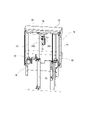
- FIG. 6 is a perspective view showing an embodiment of an automatic tool changer provided in the multi-tasking machine 1.
- FIG. 7 is a side view showing the positional relationship of the automatic tool changer in the multi-tasking machine 1.
- the automatic tool changing device 8 is arranged in the center of the front portion of the machine body of the multi-tasking machine 1, and in particular, a tool magazine 11 for storing a plurality of tools T so as to be indexable is provided on the upper part of the machine body.
- the automatic tool changer 8 is configured to replace the tool T with respect to the tool spindle device 2, and includes a tool magazine 11 located at the upper part of the machine body and a spindle head 131 located at a lower position. A shift device for moving the tool T between them is provided.
- FIG. 8 is an external perspective view of the entire multi-tasking machine 1.
- the automatic tool changing device 8 and the work transfer machine 9 are covered with a machine body cover 100 as shown in FIG.
- the gantry-type automatic work transfer machine 9 is provided so as to protrude upward from the machine body cover 100, and is configured to move the gripped work W in three axial directions inside the machine body.
- An operation panel 10 is provided in the center on the front surface of the machine body, and a left front door 151 and a right front door 152 are formed on both left and right sides thereof.
- the tool spindle device 2 is located at the back of the operation panel 10, and the work W gripped by the first work spindle device 3 and the second work spindle device 4 is machined at the back of the left front door 151 and the right front door 152. There is a processing room for.
- the automatic tool changer 8 is arranged so that the tool magazine 11 protrudes forward from the left and right front doors 151 and 152 on the front surface of the machine body, and is covered by the magazine cover 153.
- FIG. 9 is a perspective view showing the automatic tool changer 8 from the back side of the machine body (opposite side of FIG. 6).
- the tool magazine 11 of the automatic tool changer 8 is configured so that a plurality of tools T are suspended from the top plate 12 and the corresponding tool T is moved to the indexing position P11 provided in the center.
- the top plate 12 is long in the width direction of the machine body, and a pair of sprockets are provided at both ends in the longitudinal direction on the lower side thereof, and an endless roller chain 13 is hung on the top plate 12.
- the tool magazine 11 is provided with an indexing servomotor 14 on one of a pair of sprockets, and its rotation is transmitted to the roller chain 13 via a speed reducer.
- a detachable tool holder 15 (see FIG. 11) is attached to the tool T, so that the tool T can be held by the roller chain 13 and by the shift device which is conveyed between the tool magazine 11 and the tool spindle device 2. It is possible.
- the tool holder 15 is a cap-shaped member that is fitted to the head portion of the tool T, and is shaped so that the tool T can be handled by the roller chain 13 or the shift device. It should be noted that although the tools T shown in each drawing are all cylindrical, this is merely expressed by omitting various tools T without specifically showing them.
- the roller chain 13 is formed with a plurality of pot holders 201 (see FIG. 11) for holding such a tool holder 15 at regular intervals.
- the pot holder 201 is a claw member that sandwiches the side portions of the tool holder 15 from both sides at two points above and below, and projects horizontally to the outer peripheral side of the roller chain 13.
- the tool holder 15 has a groove-shaped grip portion 202 formed on the side surface into which the pot holder 201 enters, and is hooked on the roller chain 13. Therefore, the plurality of tools T stored in the tool magazine 11 are attached to the annular roller chain 13 and arranged at equal intervals along the oval moving line, and can be removed toward the outside of the circumference. ing.
- the tool T to which the tool holder 15 is fitted is held by the roller chain 13 in a hanging posture with a machined portion such as a cutting edge facing down.
- the shift device of the automatic tool changing device 8 conveys the tool T to the tool changing position with respect to the tool spindle device 2 while keeping the hanging posture.
- the shift device includes front and rear shifters 21 for attaching and detaching the tool T to and from the roller chain 13, and upper and lower shifters 22 for moving the tool T to the tool exchange position.
- the automatic tool changer 8 is provided with a tool changer 23 at the tool change position in order to change the tool T between the spindle head 131 and the upper and lower shifters 22.
- FIG. 10 and 11 are views showing the front and rear shifters 21, in particular FIG. 10 is a perspective view of the front and rear shifters 21 assembled to the top plate 12, and FIG. 11 shows the movement of the tool T by the front and rear shifters 21. It is a side view.
- the front and rear shifters 21 are assembled in the center of the upper part of the tool magazine 11.
- an air cylinder 31 having a piston rod 210 protruding rearward of the machine body (right side in FIG. 7) is fixed to the top plate 12 via a support block 38, and a pot clamper head 32 is fixed to the tip of the piston rod 210. ing.
- FIG. 12 is a side view of each detachable part from the pot clamper head 32 to the tool T in a separated state.
- the front and rear shifters 21 have a structure in which the pot clamper 35 can be attached to and detached from the pot clamper head 32.
- the pot clamper 35 is fixed so that the pull bolt 203 protrudes from the upper surface, and the pot clamper head 32 is provided with a pull clamp on the lower surface portion for detachably gripping the pull bolt 203.
- the front-rear shifter 21 moves the tool T between the front-rear conversion position P1 and the vertical conversion position P2.
- the front-rear conversion position P1 is the indexing position P11 shown in FIG. 9, which is a position where the tool T can be switched between the movement in the circumferential direction by the roller chain 13 and the movement in the front-rear direction of the machine body by the front-rear shifter 21.
- a notch 204 is formed in the top plate 12 at the front-rear conversion position P1 so that the pot clamper 35 arranged there can clamp the tool holder 15 of the indexed tool T.
- the pot clamper 35 is assembled with a plate-shaped movable block 206 attached to an L-shaped fixed block 205 in a state where the plate-shaped movable block 206 can be displaced in the front-rear direction by a support pin 207.
- the support pin 207 is urged by the clamp spring 208, and the movable block 206 is always attracted to the fixed block 205 side.
- Clamp protrusions 209 are formed on the inner side surfaces of the fixed block 205 and the movable block 206, and clamp grooves 153 into which the clamp protrusions 209 are fitted are formed on both front and rear sides of the tool holder 15. Therefore, at the vertical conversion position P2 shown on the right side of FIG. 11, the tool holder 15 is held so as to be gripped by the pot clamper 35 by the urging force of the clamp spring 208.
- the movable block 206 has locking pins 211 protruding on both sides in the lateral direction orthogonal to the moving direction, and the locking pins 211 are applied to the stop pins 213 protruding downward from the top plate 12 at the front-rear conversion position P1. .. Therefore, at the front-rear conversion position P1 shown on the left side of FIG. 11, when moving from the vertical conversion position P2 side, the locking pin 211 hits the stop pin 213, the movable block 206 cannot approach the fixed block 205, and the pot The open state of the clamper 35 is created. Further, when the pot holder 201 is moved to the front-rear conversion position P1, the pot holder 201 is fitted into the grip portion 202, and the tool T is held by the roller chain 13 via the tool holder 15.
- the moving tool T to be conveyed can be switched between the front-rear movement of the machine by the front-rear shifter 21 and the movement of the machine in the vertical direction by the up-down shifter 22.
- the tool T is transferred by the front and rear shifters 21 and the upper and lower shifters 22 by attaching and detaching the pot clamper head 32 and the pot clamper 35.
- the pot clamper 35 is configured to be gripped by the upper and lower shifters 22. That is, the pot clamper 35 has a gripping block 212 overhanging on both sides in the lateral direction like the locking pin 211, and a U-shaped notch 215 is formed in the overhanging portion as shown in FIG. There is. Then, by inserting the clamp pin 43 (see FIG. 15) into the notch portion 215, the pot clamper 35 can be gripped by the upper and lower shifters 22.
- FIG. 13 and 14 are perspective views showing the upper and lower shifters 22, and the ascending position and the descending position in the tool transfer are drawn.
- FIG. 15 is a perspective view showing the clamp portion 40 of the upper and lower shifters 22.
- the elevating frame 41 includes a clamp portion 40 and moves up and down according to the vertical guide rail 42.
- the two guide rails 42 are supported by the upper block 51 and the lower plate 52 fixed to the frame 85 side of the automatic tool changer 8, and the elevating frame 41 is supported by slide portions 221 provided at four positions on the upper, lower, left and right sides. It is configured to slide the guide rail 42.
- the clamp portion 40 is assembled to the upper beam 222 of the elevating frame 41 and is formed so that the held tool T can be accommodated in the frame.
- the clamp portion 40 has a clamp pin 43 protruding downward.
- the clamp pin 43 enters the notch portion 215 of the gripping block 212 relative to the notch portion 215 of the gripping block 212 when the tool T is moved to the vertical conversion position P2 by the front-rear shifter 21.
- the clamp pin 43 penetrates the downward tubular guide 44 fixed to the upper beam 222 and is connected to the air cylinder 45 fixed to the upper surface of the upper beam 222.
- a bracket 46 is pinned to a piston rod protruding vertically upward, and clamp pins 43 are pinned to both ends of the bracket 46.
- the clamp pin 43 has a truncated cone-shaped flange portion 223 whose lower end portion extends like an umbrella, and a concave portion matching the shape of the flange portion 223 is formed on the lower surface side of the gripping block 212.
- a positioning frame 47 is fixed to the lower side of the upper beam 222, and a notch 225 into which the grip portion 202 of the tool holder 15 is fitted is formed by the movement of the tool T toward the vertical conversion position P2. Therefore, at the vertical conversion position P2, the tool holder 15 is fitted into the positioning frame 47, and the clamp pin 43 is also inserted into the notch 215 of the pot clamper 35. In this state, when the air cylinder 45 pulls up the clamp pin 43, the gripping block 212 is sandwiched between the flange portion 223 and the cylindrical guide 44, and the pot clamper 35 is held on the clamp portion 40 side.
- the upper and lower shifters 22 are configured to raise and lower the elevating frame 41 by a ball screw mechanism. Therefore, an elevating servomotor 53 having a rotating shaft protruding vertically upward is fixed to the lower plate 52, and the rotating shaft and the screw shaft 54 are connected to each other. The upper end of the screw shaft 54 is rotationally supported by the bearing 56 of the support block 55 and penetrates the nut member 57 fixed to the elevating frame 41. The support block 55 is also fixed to the frame 85 side of the automatic tool changer 8.
- the elevating frame 41 can be raised at an accurate height by controlling the rotation of the screw shaft 54 in the elevating servomotor 53. Positioning to stop is performed.
- the support block 55 is provided with a stopper 58 so that the lower beam 226 can be applied to stop the elevating frame 41 when a control problem occurs.
- the same configuration is provided by the stopper at the descending position shown in FIG.
- FIG. 16 is a perspective view showing the tool changer 23.
- the tool changer 23 includes a tool change arm 65 having chucks 231 for gripping the tool T at both ends, a cam device 63 for turning the tool change arm 65, and a turning servomotor 61 for outputting rotation to the cam device 63. It is composed of such things.
- the input shaft 232 projects upward, and the timing belt 62 is hung between the cam device 63 and the output shaft of the turning servomotor 61 via pulleys of each shaft.
- the cam device 63 outputs a predetermined motion according to the rotation angle on the input side so that the rotary motion and the vertical motion can be output from the output shaft 233 protruding downward by the rotation input from the input shaft 232. It is composed of a groove cam and a global cam designed to be used. The vertical movement of the output shaft 233 moves within a range of heights between the lowered left side and the raised right side, as shown in FIG. Therefore, the tool changer 23 can adjust the turning angle and the displacement in the vertical direction with respect to the tool changing arm 65 by controlling the rotation of the turning servomotor 61.
- FIG. 17 is a view showing the tool change arm 65 from the lower side
- FIG. 18 is a cross-sectional view of the tool change arm 65 cut in the longitudinal direction.
- a pair of chucks 231 are symmetrically configured with reference to the rotation center O.
- the clamped state of the tool T is shown on the left side
- the unclamped state is shown on the right side.
- the tool exchange arm 65 is a linear member, and chucks 231 for gripping the tool T are formed at both ends of the arm main body 241 by a fixed claw 235 and a movable claw 236.
- the movable claw 236 is smaller than the fixed claw 235 and is swingably supported by the fulcrum pin 237 at a position close to the center of rotation O, and the connecting pin 238 is fixed to the opposite side of the toe with the fulcrum pin 237 interposed therebetween. ..
- the chuck 231 has two convex portions 239 formed on the fixed claw 235 and the movable claw 236 so that the tool T can be securely gripped, and the convex portion 239 enters the neck portion of the tool T.
- a recess 228 (see FIG. 15) is formed.
- the chuck 231 is configured so that the convex portion 239 can grip the tool T at an angle ⁇ exceeding 180 degrees by swinging the movable claw 236.
- the tool exchange arm 65 has an internal space that serves as a guide 242 formed in the arm body 241 and incorporates a slide 243 that is linearly displaced in the longitudinal direction.
- the slide 243 has a connecting elongated hole 245 formed at the end thereof, and a connecting pin 238 fixed to the movable claw 236 is inserted therein to convert the linear displacement of the slide 243 and the swinging displacement of the movable claw 236.
- the link mechanism is configured.
- the connecting elongated hole 245 is formed long in the lateral direction orthogonal to the displacement direction of the slide 243.
- a chuck spring 246 is incorporated in the guide 242, and a urging force acts on the slide 243 toward the movable claw 236, so that the movable claw 236 is normally maintained in an open state (FIG. FIG. 17 right side).
- the tool change arm 65 is configured to reduce the striking noise generated when the fixed claw 235 and the movable claw 236 grip the tool T.
- the conventional chuck has a configuration in which the tool T is gripped by the urging force of the spring, it is necessary to hold down the tool T with a large force in order to prevent the tool T from falling off, and the chuck is shrunk when gripping the tool T.
- the repulsive force of the spring that was applied generated a loud hitting sound.
- the tool change arm 65 is provided with a lock mechanism for preventing the gripped tool T from falling off without using a spring for gripping the tool T.
- a lock elongated hole 247 is formed along the displacement direction at the end on the O side of the rotation center opposite to the connecting elongated hole 245, and the lock pin 248 is inserted therein.
- the lock pin 248 has a lock portion 251 having a large diameter and a guide portion 252 having a small diameter, and is housed in a bowl-shaped guide cap 249 fixed to the lower surface side of the arm main body 241.
- the lock pin 248 has a diameter such that the guide portion 252 penetrates the long lock hole 247, and protrudes upward through the guide cylinder 255 fixed to the upper surface side of the arm main body 241.
- the large-diameter lock portion 251 is formed with a cylindrical portion that slides inside the cylindrical guide cap 249 and a lock portion whose width is narrowed so as to enter the locking elongated hole 247.
- the lock pin 248 has a lock spring 248 inserted in a hole drilled in the lower surface, and is supported by a guide cap 249 and urged upward. As shown on the right side of FIGS. 17 and 18, the lock pin 248 in the normal state in which the movable claw 236 is opened is displaced from the position of the long hole 247 for locking, so that the lock portion 251 is abutted against the slide 243. There is. On the other hand, when the tool change arm 65 grips the tool T, the movable claw 236 swings due to the tool T, and the slide 243 is displaced toward the rotation center O side as shown on the left side of FIGS. 17 and 18. It becomes. Therefore, the urged lock pin 248 rises and a part of the lock portion 251 enters the lock elongated hole 247, so that the gripping state in which the tool T does not fall off can be maintained.
- the tool changer 23 is arranged near the tool spindle device 2 in the machining chamber. Therefore, it is necessary to prevent chips, chips, or coolant generated during machining of the work W from entering the automatic tool changer 8 side.
- the automatic tool changing device 8 is provided with an outer cover 70 and a machine inner cover 71, and an upper and lower shifter 22 is provided so that the elevating frame 41 can move between them.
- a viewing window 271 fitted with glass is formed on the outer cover 70.
- a replacement window 272 is formed on the machine inner cover 71 for preventing intrusion of chips and the like, and a tool replacement shutter 72 for opening and closing the replacement window 272 according to tool replacement is provided on the processing chamber side.
- the arm storage box 73 is formed on the tool exchange shutter 72.
- FIG. 19 is a perspective view showing the tool change shutter 72, and is a view shown from the outside (left side of FIG. 7) of the processing chamber shown in FIG.
- the tool exchange shutter 72 is three-dimensionally formed, and a breakage detection sensor 75 is attached to a bracket 74 fixed to the upper portion thereof.
- the breakage detection sensor 75 applies a swinging needle 261 to the tip portion of the tool T having the same height to confirm the presence or absence of breakage.
- a bracket 76 is fixed to the ceiling surface inside the tool change shutter 72 (front side of the drawing), and the upper end portions of the two guide rails 77 and the tip portion of the piston rod 263 of the elevating air cylinder 78 are fixed. .. Then, the base bracket 79 is fixed to the frame 85 side of the automatic tool changer 8 so as to be located below the raised tool change shutter 72, and the slide member 81 on which the guide rail 77 slides and the elevating air The cylinder 78 is fixed. Therefore, the tool replacement shutter 72 rises to the position shown by the solid line in FIG. 9 by the extension operation of the elevating air cylinder 78, and lowers to the position shown by the alternate long and short dash line by the contraction operation so that the replacement window 272 opens. It is configured in.
- the tool change is performed with respect to the tool spindle device 2 as follows.
- the multi-tasking machine 1 sandwiches the tool spindle device 2 by the two advanced separation shutters 140 even while the machining is being executed in the first work spindle device 3 and the second work spindle device 4, and is used for machining. Tools can be changed without being affected.
- the spindle head 131 stands by at the tool change position due to the movement in the Y-axis direction on the base slide 134 and the movement in the X-axis direction on the spindle slide 135.
- a plurality of tools T in which the roller chain 13 is rotated and held are simultaneously moved in the circumferential direction by the drive control of the indexing servomotor 14, and the corresponding tool T is used. Is moved to the indexing position P11 shown in FIG. 9, and indexing is performed.
- the indexing position P11 is the front-rear conversion position P1 shown in FIG. 11, and the pot clamper 35 stands by in the open state. Therefore, the tool holder 15 of the indexed tool T enters the pot clamper 35.
- the tool T positioned at the front-back conversion position P1 is moved to the up-down conversion position P2 by the front-back shifter 21.
- the pot clamper head 32 equipped with the pot clamper 35 horizontally moves from the front-rear conversion position P1 to the vertical conversion position P2 due to the extension operation of the air cylinder 31.
- the movable block 206 sandwiches the tool holder 15 with the fixed block 205 by the urging force of the clamp spring 208.
- the movable block 206 and the fixed block 205 hold the tool holder 15 by engaging the clamp protrusions 209 with the clamp grooves 153.
- the clamp pin 43 When the tool T is moved to the vertical conversion position P2 by the front-rear shifter 21, the clamp pin 43 enters the notch 215 of the grip block 212, and the grip portion 202 of the tool holder 15 fits into the notch 225 of the positioning frame 47. Clamp. Then, the clamp pin 43 is pulled up by the extension operation of the air cylinder 45, and the gripping block 212 is sandwiched between the flange portion 223 and the cylindrical guide 44. After the tool T is gripped by the clamp portion 40, the elevating frame 41 is slightly lowered, so that the pull bolt 203 of the pot clamper 35 is disengaged from the pot clamper head 32. The separated pot clamper head 32 is retracted to the front-rear conversion position P1 side by the contraction operation of the air cylinder 31. In this way, the transfer of the tool T from the front and rear shifters 21 to the upper and lower shifters 22 is completed.
- the rotation of the screw shaft 54 is converted into the vertical movement of the elevating frame 41 by the drive of the elevating servomotor 53, and the tool T held by the clamp portion 40 is shown in FIG. 14 from the height shown in FIG. It will descend to the indicated tool change position.
- the tool change position is the height corresponding to the tool changer 23 on the processing chamber side shown in FIG. 7.
- the tool change arm 65 of the tool changer 23 is taken out from the arm storage box 73.
- the tool change arm 65 is located between the new tool T held by the upper and lower shifters 22 and the used tool T mounted on the tool spindle device 2.
- the tool changer 23 turns both tool Ts by 90 degrees by turning the tool change arm 65 in the state shown in FIG. 16 by a pair of chucks 231.
- the tool change arm 65 is swiveled by the output of the swivel servomotor 61, but the output shaft 233 is maintained in the contracted state shown on the right side of FIG. That is, the height of the tool change arm 65 does not change, and the lock pin 248 remains in contact with the pressing ring 69.
- the chuck 231 in the open state hits the neck of the tool T, and the movable claw 236 swings around the fulcrum pin 237.
- the movable claw 236 is closed, the tool T is gripped by the movable claw 236 and the fixed claw 235, and the convex portion 239 enters the concave portion 228.
- the slide 243 is pushed against the urging force of the chuck spring 246 via the connecting pin 238, and the position of the locking elongated hole 247 is displaced. Even at this stage, the lock pin 248 remains in contact with the pressing ring 69.
- the output shaft 233 and the tool change arm 65 are lowered to the height shown on the left side of FIG. 18 by the cam mechanism in the cam device 63.
- the lock pin 248 released from the presser foot of the pressing ring 69 rises in the arm body 241 by the urging force of the locking spring 248, and the lock portion 251 is placed in the locking elongated hole 247. It gets in and becomes locked.
- the tool change arm 65 holding the tool T is lowered, the tool T is removed from the tool holder 15 in the upper and lower shifters 22, and the tool T is also removed from the tool mounting portion of the spindle head 131.
- the lock pin 248 hits the pressing ring 69 to release the lock
- the tool T gripped by the tool changer arm 65 is mounted on the tool holder 15 on the upper and lower shifters 22 and on the tool mounting portion on the spindle head 131. Will be done.
- the tool change arm 65 turns 90 degrees in the opposite direction and returns to the standby state shown in FIG.
- the tool change shutter 72 is closed, and the height of the cutting edge of the used tool T moved to the upper and lower shifters is adjusted according to the breakage detection sensor 75. Then, the breakage is confirmed by swinging the needle 261 of the breakage detection sensor 75, and if the needle 261 hits, it is determined that the tool T is normal, and if it does not hit, it is determined that the breakage has occurred, and subsequent processing such as an alarm is performed. Is done. If the tool T is not broken, the elevating frame 41 of the upper and lower shifters 22 is raised, the pot clamper 35 is transferred to the pot clamper head 32 of the front and rear shifters 21, and the used tool T is returned to the tool magazine 11. ..
- the tool spindle device 2 is provided on the opposed biaxial lathe provided with the first and second turret devices 5 and 6 with respect to the first and second work spindle devices 3 and 4. Although it is a processing machine 1, since each device is mounted on a slant bed type base 7 and the moving range of each device is narrowed, the whole can be made compact, and it can be installed in a factory. Space can be saved. Further, in the present embodiment, the automatic tool changing device 8 for the tool spindle device 2 is provided at the front portion of the machine body, so that the multi-tasking machine 1 can be installed in a small space without increasing the size.
- the automatic tool changer 8 arranges a tool magazine 11 in the upper center of the front surface of the machine body, and has a shift device (front and rear shifters 21 and upper and lower shifters 22) for moving tools between the tool magazine 11 and the tool changer 23. By providing it, it is suitable for saving space of the entire multi-tasking machine 1.
- the automatic tool changer 8 is a tool magazine 11 that constitutes an oval tool movement line long in the machine width direction by an endless roller chain, many tools can be compactly stored in the machine width direction.
- the automatic tool changer 8 can transfer a tool whose direction is changed by the front-rear shifter 21 and the upper and lower shifter 22 between the tool magazine 11 for moving the tool in the circumferential direction and the tool changer 23 located below. ing.
- the tool holder 15 pot clamper head 32 and the pot clamper 35 are detachable members that can be directly or indirectly attached to and detached from the tool T, the tool changer 23 and the front and rear shifters 21 are used. And the tool T in the upper and lower shifters 22 can be delivered.
- the tool change arm 65 swings the movable claw 236 in the constantly open state by the urging force of the chuck spring 246, grips the tool T with the fixed claw 235, and then locks the gripped state with the lock pin 248. Since it is maintained by a mechanism, it does not make a loud hitting sound when gripping the tool T as in the conventional case. Further, the chuck 231 grips the tool T by the fixed claw 235 and the movable claw 236 within a range of an angle ⁇ exceeding 180 degrees, and the convex portion 239 is inserted into the concave portion 228, so that the gripping state of the tool T is stabilized. be able to.
- the automatic tool change device 8 can prevent the intrusion of chips, coolant, and the like scattered in the processing chamber of the multi-tasking machine 1. Further, although the tool changer 23 is arranged in the machining chamber, since the tool change shutter 72 is provided with the arm storage box 73, the tool change arm 65 is protected from chips and chips generated during machining of the work. be able to. Further, by providing the breakage detection sensor 75 in the tool exchange shutter 72, it is not necessary to provide a special mounting location.
- the present invention is not limited to these, and various modifications can be made without departing from the spirit of the present invention.
- the multi-tasking machine to which the automatic tool changer is attached is not limited to the structure of the present embodiment.
Abstract
Cet échangeur d'outil automatique est disposé dans une machine de traitement combinée qui présente un dispositif broche porte-outil au centre d'un tour à deux broches opposées, représentant un gain de place de la machine de traitement combinée. L'échangeur d'outils automatique possède : un magasin d'outils qui est disposé au niveau de la partie supérieure de la surface avant d'un corps de machine de la machine de traitement combinée et qui loge une pluralité d'outils en vue d'un échange par rapport au dispositif broche porte-outil ; un dispositif de commutation qui déplace les outils entre une position d'échange d'outil pour le dispositif broche porte-outil et le magasin d'outil ; un changeur d'outil destiné à échanger les outils entre le dispositif de commutation et le dispositif broche porte-outil.
Priority Applications (3)
| Application Number | Priority Date | Filing Date | Title |
|---|---|---|---|
| JP2022555021A JPWO2022074755A1 (fr) | 2020-10-07 | 2020-10-07 | |
| US18/040,865 US20230302593A1 (en) | 2020-10-07 | 2020-10-07 | Automatic tool exchanger |
| PCT/JP2020/037968 WO2022074755A1 (fr) | 2020-10-07 | 2020-10-07 | Échangeur d'outil automatique |
Applications Claiming Priority (1)
| Application Number | Priority Date | Filing Date | Title |
|---|---|---|---|
| PCT/JP2020/037968 WO2022074755A1 (fr) | 2020-10-07 | 2020-10-07 | Échangeur d'outil automatique |
Publications (1)
| Publication Number | Publication Date |
|---|---|
| WO2022074755A1 true WO2022074755A1 (fr) | 2022-04-14 |
Family
ID=81125725
Family Applications (1)
| Application Number | Title | Priority Date | Filing Date |
|---|---|---|---|
| PCT/JP2020/037968 WO2022074755A1 (fr) | 2020-10-07 | 2020-10-07 | Échangeur d'outil automatique |
Country Status (3)
| Country | Link |
|---|---|
| US (1) | US20230302593A1 (fr) |
| JP (1) | JPWO2022074755A1 (fr) |
| WO (1) | WO2022074755A1 (fr) |
Cited By (2)
| Publication number | Priority date | Publication date | Assignee | Title |
|---|---|---|---|---|
| CN117862960A (zh) * | 2024-03-11 | 2024-04-12 | 科德数控股份有限公司 | 一种叶片阵列机及制造方法 |
| CN117862960B (zh) * | 2024-03-11 | 2024-05-14 | 科德数控股份有限公司 | 一种叶片阵列机及制造方法 |
Citations (7)
| Publication number | Priority date | Publication date | Assignee | Title |
|---|---|---|---|---|
| JPS5947136A (ja) * | 1982-09-07 | 1984-03-16 | Matsuura Kikai Seisakusho:Kk | 工作機械の工具交換装置 |
| JPS61127936U (fr) * | 1985-01-29 | 1986-08-11 | ||
| JPS6374534A (ja) * | 1986-09-12 | 1988-04-05 | Tsugami Corp | 複合加工工作機械 |
| JP2002126962A (ja) * | 2000-10-25 | 2002-05-08 | Nippei Toyama Corp | 工具交換装置 |
| KR200471002Y1 (ko) * | 2011-03-02 | 2014-01-28 | 코요 프레시젼 컴퍼니 리미티드 | 머신닝 센터의 툴 매거진 및 툴 체인저 |
| KR20150014812A (ko) * | 2013-07-30 | 2015-02-09 | 현대위아 주식회사 | 복합가공기 |
| WO2017017825A1 (fr) * | 2015-07-29 | 2017-02-02 | 株式会社牧野フライス製作所 | Procédé et dispositif de remplacement d'outil |
-
2020
- 2020-10-07 US US18/040,865 patent/US20230302593A1/en active Pending
- 2020-10-07 JP JP2022555021A patent/JPWO2022074755A1/ja active Pending
- 2020-10-07 WO PCT/JP2020/037968 patent/WO2022074755A1/fr active Application Filing
Patent Citations (7)
| Publication number | Priority date | Publication date | Assignee | Title |
|---|---|---|---|---|
| JPS5947136A (ja) * | 1982-09-07 | 1984-03-16 | Matsuura Kikai Seisakusho:Kk | 工作機械の工具交換装置 |
| JPS61127936U (fr) * | 1985-01-29 | 1986-08-11 | ||
| JPS6374534A (ja) * | 1986-09-12 | 1988-04-05 | Tsugami Corp | 複合加工工作機械 |
| JP2002126962A (ja) * | 2000-10-25 | 2002-05-08 | Nippei Toyama Corp | 工具交換装置 |
| KR200471002Y1 (ko) * | 2011-03-02 | 2014-01-28 | 코요 프레시젼 컴퍼니 리미티드 | 머신닝 센터의 툴 매거진 및 툴 체인저 |
| KR20150014812A (ko) * | 2013-07-30 | 2015-02-09 | 현대위아 주식회사 | 복합가공기 |
| WO2017017825A1 (fr) * | 2015-07-29 | 2017-02-02 | 株式会社牧野フライス製作所 | Procédé et dispositif de remplacement d'outil |
Cited By (2)
| Publication number | Priority date | Publication date | Assignee | Title |
|---|---|---|---|---|
| CN117862960A (zh) * | 2024-03-11 | 2024-04-12 | 科德数控股份有限公司 | 一种叶片阵列机及制造方法 |
| CN117862960B (zh) * | 2024-03-11 | 2024-05-14 | 科德数控股份有限公司 | 一种叶片阵列机及制造方法 |
Also Published As
| Publication number | Publication date |
|---|---|
| JPWO2022074755A1 (fr) | 2022-04-14 |
| US20230302593A1 (en) | 2023-09-28 |
Similar Documents
| Publication | Publication Date | Title |
|---|---|---|
| US9902034B2 (en) | Automatic tool changer and machine tool | |
| KR102391258B1 (ko) | 공작 기계 | |
| US4571796A (en) | Lathe | |
| US8549964B2 (en) | Machine tool for turning operations | |
| JP2017080870A (ja) | 工作機械、特に多重スピンドルフライス盤 | |
| JP4219342B2 (ja) | 工作機械の工具交換装置 | |
| JPH04283003A (ja) | Nc旋盤における往復台構造 | |
| JP2017136683A (ja) | 工作機械 | |
| JPS6374534A (ja) | 複合加工工作機械 | |
| JP2017136682A (ja) | 工作機械、特に多重スピンドルのフライス盤 | |
| JP5497582B2 (ja) | 横型マシニングセンタ | |
| JP2016055371A (ja) | 工作機械 | |
| JP2018001364A (ja) | 工作機械ユニット | |
| JP2019048371A (ja) | 工作機械、特に多軸旋削加工機 | |
| WO2022074755A1 (fr) | Échangeur d'outil automatique | |
| US20080228313A1 (en) | Device and Method for Turning In Virtual Planes | |
| JP2019030957A (ja) | 工作機械、特に多軸旋削加工機 | |
| JP2003200329A (ja) | 複合加工用工作機械 | |
| JPS6128460B2 (fr) | ||
| JP4722636B2 (ja) | 複合旋盤の工具交換装置 | |
| WO2022091266A1 (fr) | Machine de traitement combiné | |
| JPH0542401A (ja) | Nc工作機械 | |
| JP6995214B2 (ja) | 芯出し治具 | |
| WO2022091260A1 (fr) | Machine de travail combinée | |
| JP2678856B2 (ja) | 複合工作機械の工具取付装置 |
Legal Events
| Date | Code | Title | Description |
|---|---|---|---|
| 121 | Ep: the epo has been informed by wipo that ep was designated in this application |
Ref document number: 20956703 Country of ref document: EP Kind code of ref document: A1 |
|
| ENP | Entry into the national phase |
Ref document number: 2022555021 Country of ref document: JP Kind code of ref document: A |
|
| NENP | Non-entry into the national phase |
Ref country code: DE |
|
| 122 | Ep: pct application non-entry in european phase |
Ref document number: 20956703 Country of ref document: EP Kind code of ref document: A1 |