WO2022074755A1 - Automatic tool exchanger - Google Patents
Automatic tool exchanger Download PDFInfo
- Publication number
- WO2022074755A1 WO2022074755A1 PCT/JP2020/037968 JP2020037968W WO2022074755A1 WO 2022074755 A1 WO2022074755 A1 WO 2022074755A1 JP 2020037968 W JP2020037968 W JP 2020037968W WO 2022074755 A1 WO2022074755 A1 WO 2022074755A1
- Authority
- WO
- WIPO (PCT)
- Prior art keywords
- tool
- automatic
- machine
- changer
- spindle
- Prior art date
Links
- 238000012545 processing Methods 0.000 claims abstract description 29
- 230000008859 change Effects 0.000 claims description 55
- 238000003754 machining Methods 0.000 claims description 46
- 210000000078 claw Anatomy 0.000 claims description 35
- 230000033001 locomotion Effects 0.000 claims description 32
- 230000007246 mechanism Effects 0.000 claims description 21
- 238000003825 pressing Methods 0.000 claims description 8
- 238000001514 detection method Methods 0.000 claims description 7
- 238000006073 displacement reaction Methods 0.000 claims description 7
- 238000003860 storage Methods 0.000 claims description 5
- 238000000034 method Methods 0.000 claims description 4
- 230000008569 process Effects 0.000 claims description 4
- 238000005192 partition Methods 0.000 claims description 2
- 230000003028 elevating effect Effects 0.000 description 23
- 238000006243 chemical reaction Methods 0.000 description 21
- 238000012546 transfer Methods 0.000 description 10
- 238000005520 cutting process Methods 0.000 description 6
- 150000001875 compounds Chemical class 0.000 description 4
- 238000000926 separation method Methods 0.000 description 4
- 230000001174 ascending effect Effects 0.000 description 3
- 230000008602 contraction Effects 0.000 description 3
- 239000002826 coolant Substances 0.000 description 3
- 238000013459 approach Methods 0.000 description 2
- 239000002131 composite material Substances 0.000 description 2
- 240000007594 Oryza sativa Species 0.000 description 1
- 235000007164 Oryza sativa Nutrition 0.000 description 1
- 230000005540 biological transmission Effects 0.000 description 1
- 239000003638 chemical reducing agent Substances 0.000 description 1
- 238000005553 drilling Methods 0.000 description 1
- 230000000694 effects Effects 0.000 description 1
- 239000011521 glass Substances 0.000 description 1
- 239000000463 material Substances 0.000 description 1
- 238000012986 modification Methods 0.000 description 1
- 230000004048 modification Effects 0.000 description 1
- 230000002093 peripheral effect Effects 0.000 description 1
- 235000009566 rice Nutrition 0.000 description 1
Images


Classifications
-
- B—PERFORMING OPERATIONS; TRANSPORTING
- B23—MACHINE TOOLS; METAL-WORKING NOT OTHERWISE PROVIDED FOR
- B23Q—DETAILS, COMPONENTS, OR ACCESSORIES FOR MACHINE TOOLS, e.g. ARRANGEMENTS FOR COPYING OR CONTROLLING; MACHINE TOOLS IN GENERAL CHARACTERISED BY THE CONSTRUCTION OF PARTICULAR DETAILS OR COMPONENTS; COMBINATIONS OR ASSOCIATIONS OF METAL-WORKING MACHINES, NOT DIRECTED TO A PARTICULAR RESULT
- B23Q3/00—Devices holding, supporting, or positioning work or tools, of a kind normally removable from the machine
- B23Q3/155—Arrangements for automatic insertion or removal of tools, e.g. combined with manual handling
- B23Q3/157—Arrangements for automatic insertion or removal of tools, e.g. combined with manual handling of rotary tools
- B23Q3/15773—Arrangements for automatic insertion or removal of tools, e.g. combined with manual handling of rotary tools a transfer device taking the tool from a storage device and passing it on to other transfer devices, which insert it in a spindle
-
- B—PERFORMING OPERATIONS; TRANSPORTING
- B23—MACHINE TOOLS; METAL-WORKING NOT OTHERWISE PROVIDED FOR
- B23Q—DETAILS, COMPONENTS, OR ACCESSORIES FOR MACHINE TOOLS, e.g. ARRANGEMENTS FOR COPYING OR CONTROLLING; MACHINE TOOLS IN GENERAL CHARACTERISED BY THE CONSTRUCTION OF PARTICULAR DETAILS OR COMPONENTS; COMBINATIONS OR ASSOCIATIONS OF METAL-WORKING MACHINES, NOT DIRECTED TO A PARTICULAR RESULT
- B23Q3/00—Devices holding, supporting, or positioning work or tools, of a kind normally removable from the machine
- B23Q3/155—Arrangements for automatic insertion or removal of tools, e.g. combined with manual handling
- B23Q3/157—Arrangements for automatic insertion or removal of tools, e.g. combined with manual handling of rotary tools
- B23Q3/15713—Arrangements for automatic insertion or removal of tools, e.g. combined with manual handling of rotary tools a transfer device taking a single tool from a storage device and inserting it in a spindle
-
- B—PERFORMING OPERATIONS; TRANSPORTING
- B23—MACHINE TOOLS; METAL-WORKING NOT OTHERWISE PROVIDED FOR
- B23B—TURNING; BORING
- B23B11/00—Automatic or semi-automatic turning-machines incorporating equipment for performing other working procedures, e.g. slotting, milling, rolling
-
- B—PERFORMING OPERATIONS; TRANSPORTING
- B23—MACHINE TOOLS; METAL-WORKING NOT OTHERWISE PROVIDED FOR
- B23P—METAL-WORKING NOT OTHERWISE PROVIDED FOR; COMBINED OPERATIONS; UNIVERSAL MACHINE TOOLS
- B23P23/00—Machines or arrangements of machines for performing specified combinations of different metal-working operations not covered by a single other subclass
- B23P23/02—Machine tools for performing different machining operations
-
- B—PERFORMING OPERATIONS; TRANSPORTING
- B23—MACHINE TOOLS; METAL-WORKING NOT OTHERWISE PROVIDED FOR
- B23Q—DETAILS, COMPONENTS, OR ACCESSORIES FOR MACHINE TOOLS, e.g. ARRANGEMENTS FOR COPYING OR CONTROLLING; MACHINE TOOLS IN GENERAL CHARACTERISED BY THE CONSTRUCTION OF PARTICULAR DETAILS OR COMPONENTS; COMBINATIONS OR ASSOCIATIONS OF METAL-WORKING MACHINES, NOT DIRECTED TO A PARTICULAR RESULT
- B23Q3/00—Devices holding, supporting, or positioning work or tools, of a kind normally removable from the machine
- B23Q3/155—Arrangements for automatic insertion or removal of tools, e.g. combined with manual handling
- B23Q3/1552—Arrangements for automatic insertion or removal of tools, e.g. combined with manual handling parts of devices for automatically inserting or removing tools
- B23Q3/15526—Storage devices; Drive mechanisms therefor
- B23Q2003/15528—Storage devices; Drive mechanisms therefor the storage device including means to project tools therefrom, e.g. for transferring them
- B23Q2003/1553—Storage devices; Drive mechanisms therefor the storage device including means to project tools therefrom, e.g. for transferring them by rectilinear projection
-
- B—PERFORMING OPERATIONS; TRANSPORTING
- B23—MACHINE TOOLS; METAL-WORKING NOT OTHERWISE PROVIDED FOR
- B23Q—DETAILS, COMPONENTS, OR ACCESSORIES FOR MACHINE TOOLS, e.g. ARRANGEMENTS FOR COPYING OR CONTROLLING; MACHINE TOOLS IN GENERAL CHARACTERISED BY THE CONSTRUCTION OF PARTICULAR DETAILS OR COMPONENTS; COMBINATIONS OR ASSOCIATIONS OF METAL-WORKING MACHINES, NOT DIRECTED TO A PARTICULAR RESULT
- B23Q3/00—Devices holding, supporting, or positioning work or tools, of a kind normally removable from the machine
- B23Q3/155—Arrangements for automatic insertion or removal of tools, e.g. combined with manual handling
- B23Q3/1552—Arrangements for automatic insertion or removal of tools, e.g. combined with manual handling parts of devices for automatically inserting or removing tools
- B23Q3/1554—Transfer mechanisms, e.g. tool gripping arms; Drive mechanisms therefore
- B23Q2003/155414—Transfer mechanisms, e.g. tool gripping arms; Drive mechanisms therefore the transfer mechanism comprising two or more grippers
- B23Q2003/155425—Transfer mechanisms, e.g. tool gripping arms; Drive mechanisms therefore the transfer mechanism comprising two or more grippers pivotable
- B23Q2003/155428—Transfer mechanisms, e.g. tool gripping arms; Drive mechanisms therefore the transfer mechanism comprising two or more grippers pivotable about a common axis
Definitions
- the present invention relates to an automatic tool changer suitable for saving space in a multi-tasking machine.
- Patent Document 1 discloses a composite NC lathe (composite processing machine) that enables machining such as a machining center.
- This multi-tasking machine is an opposed biaxial lathe with a tool spindle capable of exchanging tools and a tool turret equipped with multiple exchange tools, and efficiently processes workpieces of various shapes from materials to finished products on the same machine. It is designed to be processed well. Specifically, it has a left main shaft and a right main shaft facing each other on the same axis, and a left turret turret turret and a right turret turret are arranged on the lower front side of both main shafts, and further, the back of both main shafts. A third turret is provided above the side.
- the conventional multi-tasking machine includes a tool magazine accommodating a plurality of tools used for the third turret, and an automatic tool changing device for exchanging the tools between the turrets. It is provided.
- the multi-tasking machine mentioned as a conventional example a plurality of tools are attached to the tool post of the tool turret arranged on the left and right in the circumferential direction, and various machining on the work is possible by swivel indexing.
- the third tool post is also provided with a tool magazine so as to be able to cope with various machining, and various tools that can be replaced with respect to the tool spindle are stored. Then, the tool is replaced with respect to the third tool post by an automatic tool changing device.
- the automatic tool changer is installed on the bed together with each device such as the turret tool post, the arrangement and configuration of the multi-tasking machine can be installed in a small space. rice field.
- an automatic tool changer is also mounted on a bed provided with left and right spindles, a turret tool post, etc., and is arranged at the left back of the bed. Therefore, in order to exchange tools for the third tool post, a structure is provided on the bed on which each device is arranged to move the tool table to the automatic tool change device, and the multi-tasking machine becomes larger by that amount. It has been done. Therefore, the conventional automatic tool changer is not suitable for realizing the space saving of the multi-tasking machine.
- an object of the present invention is to provide an automatic tool changer suitable for space saving of a multi-tasking machine in order to solve such a problem.
- the automatic tool changer according to one aspect of the present invention is provided in a multi-tasking machine in which the tool spindle device is arranged in the center of the opposed biaxial lathe, and is arranged in the upper part of the front surface of the machine body of the multi-axis machine.
- a tool magazine containing a plurality of tools for replacement with respect to the tool spindle device, a shift device for moving a tool between the tool magazine and the tool exchange position with respect to the tool spindle device, and the shift device and the tool spindle device.
- the shift device moves the tool between the tool magazine arranged on the upper front surface of the multi-tasking machine and the tool exchange position with respect to the tool spindle device, and the tool changer moves the tool with the tool spindle device. It is not necessary to move the tool spindle device as in the past, and the tool changer is arranged using the space above the front surface of the multi-tasking machine, so that the tool is moved by the shift device or tool changer. Therefore, it can be used as an automatic tool changer suitable for saving space in a multi-tasking machine.
- FIG. 2 is a perspective view, a front view, a plan view and a side view showing the main structure of the multi-tasking machine of the present embodiment.
- the multi-tasking machine 1 includes a first work spindle device 3 and a second work spindle device 4 that give rotation to the gripped work W, and a first turret device 5 and a second turret device 5 having a plurality of tools T corresponding to machining of the work W.
- the turret devices 6 are arranged symmetrically.
- the first work spindle device 3 and the second work spindle device 4 are coaxially arranged so that the chuck mechanisms 101 face each other, and each of them is provided with a first turret device 5 and a second turret device 6 which are blade bases. Has been done.
- a tool spindle device 2 for performing machining difficult with the lathe is provided in the center of the machine body.
- the first work spindle device 3, the second work spindle device 4, the first turret device 5, the second turret device 6, and the tool spindle device 2 are mounted on one base 7.
- Each device is assembled via a drive device so that it can move in a predetermined direction on the base 7.
- the moving direction (moving axis) of each device is defined and described as follows. First, the first work spindle device 3 and the second work spindle device 4 are designed so that the center line of the spindle is in the width direction of the machine body and is horizontal, and the moving direction is parallel to the spindle. , This is the Z axis.
- the first and second turret devices 5 and 6 and the tool spindle device 2 both move in the front-rear direction of the machine body orthogonal to the main axis and in the vertical direction of the machine body.
- the base 7 of the multi-tasking machine 1 is a so-called slant bed type, and the tool spindle device 2 is horizontal when moving in the front-rear direction of the machine, while the first and second turret devices 5 and 6 are inclined. There is. Therefore, the horizontal front-rear direction of the machine, which is the moving direction of the tool spindle device 2, is defined as the Y-axis, and the vertical vertical direction of the machine perpendicular to the Y-axis is defined as the X-axis.
- the tool spindle device 2 has its rotation axis parallel to the Y axis as the B axis.
- the first and second turret devices 5 and 6 have the Y-axis and the X-axis tilted by 45 degrees as the moving axes, which are the YL axis and the XL axis, respectively.
- the mounting surfaces of the first and second work spindle devices 3 and 4 arranged on the front side of the machine body are inclined so as to lower the front side, and conversely, the first first placed on the rear side of the machine body.
- the mounting surface of the second turret devices 5 and 6 is inclined so as to lower the rear.
- the front-rear inclination of the base 7 is formed so that the rear side of the machine body is larger so that the positions of the mounting surfaces of the first and second turret devices 5 and 6 are higher than the mounting surfaces of the first and second work spindle devices 3 and 4.
- the multi-tasking machine 1 of the present embodiment has a structure in which the dimensions in the front-rear direction of the machine body are suppressed by inclining the mounting surface of the base 7 in the front-rear direction.
- the first and second work spindle devices 3 and 4 (hereinafter referred to as work spindle devices 3 and 4 in the case of a description common to both devices) are configured in the same manner, and a chuck that grips and releases the work W to be machined.
- a mechanism 101 is provided. That is, in the work spindle devices 3 and 4, the spindle is rotatably incorporated into the cylindrical spindle base 102, and the chuck mechanism 101 is assembled to the tip of the spindle.
- the spindles of the work spindle devices 3 and 4 are arranged in parallel with the rotation axis of the spindle motor 103, and a belt is hung through a pulley fixed to each rotation axis, and the rotational movement of the spindle motor is transmitted via the belt. It is configured to be transmitted to the spindle. Therefore, the chuck mechanism 101 assembled to the spindle is rotated by the control of the spindle motor 103, and the gripped work W is phase-determined at the time of machining and is rotated at a predetermined speed.
- the work spindle devices 3 and 4 are mounted on the spindle slide 104 and are configured to move on the base 7 along the Z axis in the machine width direction.
- the base 7 has a front inclined surface 110 formed so that the front side is lowered, and two guide rails 105 parallel to the Z axis are fixed to the base 7.
- a guide block 106 is provided on the lower surface of the spindle slide 104 that matches the inclination of the front inclined surface 110, and is slidably meshed with the guide rail 105.
- the work spindle devices 3 and 4 are mounted on the spindle slide 104 so that the spindle 102 and the spindle motor 103 are positioned vertically so as not to protrude significantly forward from the front inclined surface 110 narrow in the front-rear direction of the machine body. ing.
- the work spindle devices 3 and 4 enable movement in the Z-axis direction by a ball screw mechanism.
- a screw shaft 107 parallel to the Z axis is supported between the two guide rails 105 via a bearing.
- a Z-axis servomotor 108 is provided on the outside in the width direction of the machine body, and its rotating shaft is connected to the screw shaft 107.
- a nut member through which the screw shaft 107 passes is fixed to the spindle slide 104, and the spindle slide 104 is configured to linearly move in the Z-axis direction by the rotational output of the Z-axis servomotor 108.
- the first turret device 5 and the second turret device 6 swing index the corresponding tool T from the plurality of tools T. It is selected by the above and performs a predetermined process such as cutting on the work W.
- a plurality of tools T are attached to the disk-shaped tool post 111 at equal intervals in the circumferential direction, and the tool table 111 is configured so that the tool T can be attached to and detached at an arbitrary position.
- the turret devices 5 and 6 have an indexing servomotor 112 for controlling the rotation of the tool post 111, and are configured to be able to position an arbitrary tool T at a machining position on the circumference.
- the tool T of the tool post 111 is attached with the tip of a cutting tool, a drill, etc. facing the outside in the machine width direction, and the work spindle devices 3 and 4 move in the Z-axis direction to the work W approaching.
- the tool T can be applied from the center side of the machine body.
- the turret devices 5 and 6 are provided with a drive device for moving the tool post 111 on an XY plane orthogonal to the Z axis so that the tool T can be moved to the machining position.
- the movement of the tool post 111 in the present embodiment is in the YL axis direction and the XL axis direction having an angle of 45 degrees with respect to the horizontal direction and the vertical direction. Therefore, a rear inclined surface 120 parallel to the YL axis is formed on the base 7, and the base slide 113 is assembled there in a movable state.
- the YL axis is high toward the front side of the machine body, and conversely, the XL axis is low toward the front side, that is, toward the work spindle devices 3 and 4.
- a YL axis guide rail 116 is fixed to the rear slope 120 of the base 7, and a substantially triangular base slide 113 is slidably assembled.
- the base slide 113 is provided with a guide portion 121 slidably meshing with the YL axis guide rail 116 on one side, and an XL axis guide rail 122 is provided on adjacent sides at 90 degrees.
- the guide portion 123 of the turret slide 115 is slidably meshed with the XL axis guide rail 122.
- Both the base slide 113 and the turret slide 115 can be moved along the YL axis and the XL axis by the ball screw mechanism.
- a screw shaft parallel to each of the YL shaft guide rail 116 and the XL shaft guide rail 122 is supported by a bearing, and the screw shaft passes through a nut member fixed to the base slide 113 or the turret slide 115.
- Each screw shaft is connected to the rotation shaft of the YL axis servo-motor 117 or the XL-axis servo motor 118, and each rotation output enables linear movement of the base slide 113 and the turret slide 115.
- the turret devices 5 and 6 control the movement of the tool post 111 in each direction of the YL axis and the XL axis by the drive control of the YL axis servomotor 117 and the XL axis servomotor 118, as well as the horizontal direction in which the movements in both axis directions are combined. It is also possible to control the movement of the servo.
- the straight line connecting the rotation center of the tool post 111 and the rotation center of the spindle in the work spindle devices 3 and 4 is the XL axis.
- the position is adjusted in the YL axis direction so as to be parallel.
- the straight line connecting both rotation centers is referred to as the machining movement line L1. Therefore, the tool T of the tool post 111 is arranged on the machining movement line L1 by swivel indexing, and positioning for machining with respect to the work W is performed by movement in the XL axis direction.
- the multi-tasking machine 1 is provided with a tool spindle device 2 in the central portion of the machine body so as to be able to handle the machining of the work W which cannot be performed by the turret devices 5 and 6.
- FIG. 5 is a side view showing the tool spindle device 2.
- the tool spindle device 2 can perform drilling and the like in addition to lathe processing on the work W gripped by the work spindle devices 3 and 4, and can process the work at a depth and angle that cannot be performed by the turret devices 5 and 6. Is what makes it possible.
- the tool spindle device 2 has a drive device for moving the tool T on an XY plane orthogonal to the Z axis, and further has a tool with a B axis having a rotation center horizontal in the Y axis direction.
- the angle of T can be adjusted.
- the tool spindle device 2 has a spindle servo motor and a tool spindle built in the spindle head 131, and is housed in an automatic tool changer 8 (see FIG. 6) with respect to a tool mounting portion provided at the lower end thereof.
- Various tools T can be replaced.
- the spindle head 131 is rotatably attached to the spindle slide 135, and is configured to transmit the rotation of the B-axis motor 132 via a rotation transmission mechanism.
- a guide rail 133 is fixed on the base 7 so that the spindle head 131 can move in the Y-axis direction, which is the front-rear direction of the machine body, and the base slide 134 is slidably assembled therein. ..
- the guide portion 137 and the rail portion 139 are configured at an angle of 90 degrees.
- the guide portion 137 is slidably meshed with the guide rail 133
- the guide portion 138 of the spindle slide 135 is slidably meshed with the rail portion 139.
- Both the base slide 134 and the spindle slide 135 can move in the Y-axis direction and the X-axis direction by the ball screw mechanism.
- a screw shaft arranged in each axial direction is supported via a bearing, and the screw shaft passes through a nut member fixed to a base slide 134 or a spindle slide 135.
- a Y-axis servomotor 141 (see FIG. 3) or an X-axis servomotor 142 is connected to each screw shaft, and the rotational output thereof enables linear movement of the base slide 134 and the spindle slide 135.
- the tool T is positioned by the drive control of the Y-axis servomotor 141 and the X-axis servomotor 142, and the posture (angle) of the tool T with respect to the work W by the drive control of the B-axis servomotor 132. Adjustment is possible.
- the work W is put into the first work spindle device 3 by the work automatic transfer machine 9, and is discharged from the second work spindle device 4. Further, the work W is directly delivered from the first work spindle device 3 to the second work spindle device 4 by both devices.
- the work W is simultaneously machined by the first work spindle device 3 and the second work spindle device 4, and the work W is conveyed or machined by the other while the work W is being machined. It is possible to replace the tool with respect to the tool spindle device 2 at the same time.
- the multi-tasking machine 1 is provided with two separation shutters 140 as shown in FIGS. 1 to 3.
- the separation shutter 140 partitions the machining chamber for machining the work W in the machine width direction, and is a first machining space by the first work spindle device 3 and the turret device 5, and the second work spindle device 4 and the second turret device. It can be divided into a second machining space according to No. 6 and a tool change space performed for the tool spindle device 2.
- These two separation shutters 140 are configured to be horizontally moved in the front-rear direction of the machine body by a driving device.
- the work W is machined according to the following flow.
- the work W gripped by the first work spindle device 3 is first processed by the first turret device 5, and then delivered to the second work spindle device 4.
- the second machining by the second turret device 6 is executed on the opposite surface of the work W on which the first machining has been performed. Further, in the first machining and the second machining, in addition to the first turret device 5 and the like, machining using the tool spindle device 2 is performed as needed.
- the work W of the input side stocker is taken out by the work automatic carrier 9, carried to the first work spindle device 3, and gripped by the chuck mechanism 101.
- the tool T used for machining the work W is swiveled and indexed from among the plurality of tools T by driving the tool post 111.
- the turret slide 115 moves to the first work spindle device 3, and the tool T enters the machining position with respect to the work W and is positioned.
- the base slide 113 at this time is positioned in the YL axis direction so that the indexed tool T moves on the machining movement line L1.
- the work W gripped by the chuck mechanism 101 is rotated by the drive of the spindle motor 103, and the spindle slide 104 moves in the Z-axis direction along the guide rail 105.
- a tool T is applied to the work W to perform predetermined machining. For example, when boring is performed on the work W, the tool T, which is a cutting tool, relatively faces the work W, and the cutting edge is applied to the inner surface of the hole formed in the rotating work W. It will be done.
- the first machining of the work W in the first work spindle device 3 is performed by the first turret device 5, the machining by adding the tool spindle device 2, or the machining by only the tool spindle device 2.
- the tool post 11 is retracted by moving in the XL axis direction so as to be separated from the first work spindle device 3.
- the spindle head 131 is positioned in the front-rear direction of the machine body and the up-down direction of the machine body by the movement in the Y-axis direction on the base slide 134 and the movement in the X-axis direction on the spindle slide 135. Then, the angle of the tool T is adjusted by the rotation of the B-axis of the spindle head 131.
- the spindle head 131 is returned to the retracted position by moving in the Y-axis direction and the X-axis direction.
- both devices approach the center of the machine body, and the second work spindle device is opposed to the first work spindle device 3 that has stopped earlier. 4 goes to pick up the work W, and the chuck mechanisms 101 re-grasp the work W.
- the work W gripped by the second work spindle device 4 is to be machined on the secondary machined surface side on the back side where the first machined is performed.
- the second machining by the second turret device 6 is executed on the work W as in the first turret device 5, or the machining by the tool spindle device 2 is added, and the tool spindle device 2 alone is used. Processing is done.
- the work W for which the second processing has been completed is taken out by the work automatic transfer machine 9 and collected in the output side stocker.
- the first turret device 5 and the tool spindle device 2 perform machining in the first machining
- the second turret device 6 and the tool spindle device 2 also perform machining in the second machining. Therefore, it is possible to increase the number of man-hours in each processing, and it is possible to perform a plurality of processing on the work W in a short time.
- the first and second work spindle devices 3, 4, the first and second turret devices 5, 6 and the tool spindle device 2 are compact on the slant bed type base 7. It is configured in and enables space saving.
- the multi-tasking machine 1 is designed so that the dimensions in the front-rear direction of the machine body are suppressed and the moving range of each device is narrowed. That is, the central portion of the combined processing machine 1 on the front side of the machine body serves as a processing chamber, and each device is configured to move between the retracted position and the processing position in a narrow space. Therefore, even in the tool spindle device 2 that requires replacement of the tool T, the spindle head 131 can move only a short distance in the front-back and up-down directions of the machine body.
- the multi-tasking machine 1 various tools T are used for the tool spindle device 2 according to the machining content of the work W, so that the corresponding tool T can be automatically replaced from the tool magazine containing a plurality of tools T. Needs an automatic tool changer.
- the multi-tasking machine 1 for the purpose of saving space has a configuration in which an automatic tool changer is arranged at a remote position on the bed 7 and the tool spindle device 2 is moved there, as in the conventional example. Can not. Therefore, in the present embodiment, automatic tool replacement having a structure in which the tool T is replaced with the tool spindle device 2 so as not to impair the effect of the multi-tasking machine 1 in which the first work spindle device 3 and the like are compactly arranged.
- the device 8 is provided.
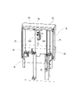
- FIG. 6 is a perspective view showing an embodiment of an automatic tool changer provided in the multi-tasking machine 1.
- FIG. 7 is a side view showing the positional relationship of the automatic tool changer in the multi-tasking machine 1.
- the automatic tool changing device 8 is arranged in the center of the front portion of the machine body of the multi-tasking machine 1, and in particular, a tool magazine 11 for storing a plurality of tools T so as to be indexable is provided on the upper part of the machine body.
- the automatic tool changer 8 is configured to replace the tool T with respect to the tool spindle device 2, and includes a tool magazine 11 located at the upper part of the machine body and a spindle head 131 located at a lower position. A shift device for moving the tool T between them is provided.
- FIG. 8 is an external perspective view of the entire multi-tasking machine 1.
- the automatic tool changing device 8 and the work transfer machine 9 are covered with a machine body cover 100 as shown in FIG.
- the gantry-type automatic work transfer machine 9 is provided so as to protrude upward from the machine body cover 100, and is configured to move the gripped work W in three axial directions inside the machine body.
- An operation panel 10 is provided in the center on the front surface of the machine body, and a left front door 151 and a right front door 152 are formed on both left and right sides thereof.
- the tool spindle device 2 is located at the back of the operation panel 10, and the work W gripped by the first work spindle device 3 and the second work spindle device 4 is machined at the back of the left front door 151 and the right front door 152. There is a processing room for.
- the automatic tool changer 8 is arranged so that the tool magazine 11 protrudes forward from the left and right front doors 151 and 152 on the front surface of the machine body, and is covered by the magazine cover 153.
- FIG. 9 is a perspective view showing the automatic tool changer 8 from the back side of the machine body (opposite side of FIG. 6).
- the tool magazine 11 of the automatic tool changer 8 is configured so that a plurality of tools T are suspended from the top plate 12 and the corresponding tool T is moved to the indexing position P11 provided in the center.
- the top plate 12 is long in the width direction of the machine body, and a pair of sprockets are provided at both ends in the longitudinal direction on the lower side thereof, and an endless roller chain 13 is hung on the top plate 12.
- the tool magazine 11 is provided with an indexing servomotor 14 on one of a pair of sprockets, and its rotation is transmitted to the roller chain 13 via a speed reducer.
- a detachable tool holder 15 (see FIG. 11) is attached to the tool T, so that the tool T can be held by the roller chain 13 and by the shift device which is conveyed between the tool magazine 11 and the tool spindle device 2. It is possible.
- the tool holder 15 is a cap-shaped member that is fitted to the head portion of the tool T, and is shaped so that the tool T can be handled by the roller chain 13 or the shift device. It should be noted that although the tools T shown in each drawing are all cylindrical, this is merely expressed by omitting various tools T without specifically showing them.
- the roller chain 13 is formed with a plurality of pot holders 201 (see FIG. 11) for holding such a tool holder 15 at regular intervals.
- the pot holder 201 is a claw member that sandwiches the side portions of the tool holder 15 from both sides at two points above and below, and projects horizontally to the outer peripheral side of the roller chain 13.
- the tool holder 15 has a groove-shaped grip portion 202 formed on the side surface into which the pot holder 201 enters, and is hooked on the roller chain 13. Therefore, the plurality of tools T stored in the tool magazine 11 are attached to the annular roller chain 13 and arranged at equal intervals along the oval moving line, and can be removed toward the outside of the circumference. ing.
- the tool T to which the tool holder 15 is fitted is held by the roller chain 13 in a hanging posture with a machined portion such as a cutting edge facing down.
- the shift device of the automatic tool changing device 8 conveys the tool T to the tool changing position with respect to the tool spindle device 2 while keeping the hanging posture.
- the shift device includes front and rear shifters 21 for attaching and detaching the tool T to and from the roller chain 13, and upper and lower shifters 22 for moving the tool T to the tool exchange position.
- the automatic tool changer 8 is provided with a tool changer 23 at the tool change position in order to change the tool T between the spindle head 131 and the upper and lower shifters 22.
- FIG. 10 and 11 are views showing the front and rear shifters 21, in particular FIG. 10 is a perspective view of the front and rear shifters 21 assembled to the top plate 12, and FIG. 11 shows the movement of the tool T by the front and rear shifters 21. It is a side view.
- the front and rear shifters 21 are assembled in the center of the upper part of the tool magazine 11.
- an air cylinder 31 having a piston rod 210 protruding rearward of the machine body (right side in FIG. 7) is fixed to the top plate 12 via a support block 38, and a pot clamper head 32 is fixed to the tip of the piston rod 210. ing.
- FIG. 12 is a side view of each detachable part from the pot clamper head 32 to the tool T in a separated state.
- the front and rear shifters 21 have a structure in which the pot clamper 35 can be attached to and detached from the pot clamper head 32.
- the pot clamper 35 is fixed so that the pull bolt 203 protrudes from the upper surface, and the pot clamper head 32 is provided with a pull clamp on the lower surface portion for detachably gripping the pull bolt 203.
- the front-rear shifter 21 moves the tool T between the front-rear conversion position P1 and the vertical conversion position P2.
- the front-rear conversion position P1 is the indexing position P11 shown in FIG. 9, which is a position where the tool T can be switched between the movement in the circumferential direction by the roller chain 13 and the movement in the front-rear direction of the machine body by the front-rear shifter 21.
- a notch 204 is formed in the top plate 12 at the front-rear conversion position P1 so that the pot clamper 35 arranged there can clamp the tool holder 15 of the indexed tool T.
- the pot clamper 35 is assembled with a plate-shaped movable block 206 attached to an L-shaped fixed block 205 in a state where the plate-shaped movable block 206 can be displaced in the front-rear direction by a support pin 207.
- the support pin 207 is urged by the clamp spring 208, and the movable block 206 is always attracted to the fixed block 205 side.
- Clamp protrusions 209 are formed on the inner side surfaces of the fixed block 205 and the movable block 206, and clamp grooves 153 into which the clamp protrusions 209 are fitted are formed on both front and rear sides of the tool holder 15. Therefore, at the vertical conversion position P2 shown on the right side of FIG. 11, the tool holder 15 is held so as to be gripped by the pot clamper 35 by the urging force of the clamp spring 208.
- the movable block 206 has locking pins 211 protruding on both sides in the lateral direction orthogonal to the moving direction, and the locking pins 211 are applied to the stop pins 213 protruding downward from the top plate 12 at the front-rear conversion position P1. .. Therefore, at the front-rear conversion position P1 shown on the left side of FIG. 11, when moving from the vertical conversion position P2 side, the locking pin 211 hits the stop pin 213, the movable block 206 cannot approach the fixed block 205, and the pot The open state of the clamper 35 is created. Further, when the pot holder 201 is moved to the front-rear conversion position P1, the pot holder 201 is fitted into the grip portion 202, and the tool T is held by the roller chain 13 via the tool holder 15.
- the moving tool T to be conveyed can be switched between the front-rear movement of the machine by the front-rear shifter 21 and the movement of the machine in the vertical direction by the up-down shifter 22.
- the tool T is transferred by the front and rear shifters 21 and the upper and lower shifters 22 by attaching and detaching the pot clamper head 32 and the pot clamper 35.
- the pot clamper 35 is configured to be gripped by the upper and lower shifters 22. That is, the pot clamper 35 has a gripping block 212 overhanging on both sides in the lateral direction like the locking pin 211, and a U-shaped notch 215 is formed in the overhanging portion as shown in FIG. There is. Then, by inserting the clamp pin 43 (see FIG. 15) into the notch portion 215, the pot clamper 35 can be gripped by the upper and lower shifters 22.
- FIG. 13 and 14 are perspective views showing the upper and lower shifters 22, and the ascending position and the descending position in the tool transfer are drawn.
- FIG. 15 is a perspective view showing the clamp portion 40 of the upper and lower shifters 22.
- the elevating frame 41 includes a clamp portion 40 and moves up and down according to the vertical guide rail 42.
- the two guide rails 42 are supported by the upper block 51 and the lower plate 52 fixed to the frame 85 side of the automatic tool changer 8, and the elevating frame 41 is supported by slide portions 221 provided at four positions on the upper, lower, left and right sides. It is configured to slide the guide rail 42.
- the clamp portion 40 is assembled to the upper beam 222 of the elevating frame 41 and is formed so that the held tool T can be accommodated in the frame.
- the clamp portion 40 has a clamp pin 43 protruding downward.
- the clamp pin 43 enters the notch portion 215 of the gripping block 212 relative to the notch portion 215 of the gripping block 212 when the tool T is moved to the vertical conversion position P2 by the front-rear shifter 21.
- the clamp pin 43 penetrates the downward tubular guide 44 fixed to the upper beam 222 and is connected to the air cylinder 45 fixed to the upper surface of the upper beam 222.
- a bracket 46 is pinned to a piston rod protruding vertically upward, and clamp pins 43 are pinned to both ends of the bracket 46.
- the clamp pin 43 has a truncated cone-shaped flange portion 223 whose lower end portion extends like an umbrella, and a concave portion matching the shape of the flange portion 223 is formed on the lower surface side of the gripping block 212.
- a positioning frame 47 is fixed to the lower side of the upper beam 222, and a notch 225 into which the grip portion 202 of the tool holder 15 is fitted is formed by the movement of the tool T toward the vertical conversion position P2. Therefore, at the vertical conversion position P2, the tool holder 15 is fitted into the positioning frame 47, and the clamp pin 43 is also inserted into the notch 215 of the pot clamper 35. In this state, when the air cylinder 45 pulls up the clamp pin 43, the gripping block 212 is sandwiched between the flange portion 223 and the cylindrical guide 44, and the pot clamper 35 is held on the clamp portion 40 side.
- the upper and lower shifters 22 are configured to raise and lower the elevating frame 41 by a ball screw mechanism. Therefore, an elevating servomotor 53 having a rotating shaft protruding vertically upward is fixed to the lower plate 52, and the rotating shaft and the screw shaft 54 are connected to each other. The upper end of the screw shaft 54 is rotationally supported by the bearing 56 of the support block 55 and penetrates the nut member 57 fixed to the elevating frame 41. The support block 55 is also fixed to the frame 85 side of the automatic tool changer 8.
- the elevating frame 41 can be raised at an accurate height by controlling the rotation of the screw shaft 54 in the elevating servomotor 53. Positioning to stop is performed.
- the support block 55 is provided with a stopper 58 so that the lower beam 226 can be applied to stop the elevating frame 41 when a control problem occurs.
- the same configuration is provided by the stopper at the descending position shown in FIG.
- FIG. 16 is a perspective view showing the tool changer 23.
- the tool changer 23 includes a tool change arm 65 having chucks 231 for gripping the tool T at both ends, a cam device 63 for turning the tool change arm 65, and a turning servomotor 61 for outputting rotation to the cam device 63. It is composed of such things.
- the input shaft 232 projects upward, and the timing belt 62 is hung between the cam device 63 and the output shaft of the turning servomotor 61 via pulleys of each shaft.
- the cam device 63 outputs a predetermined motion according to the rotation angle on the input side so that the rotary motion and the vertical motion can be output from the output shaft 233 protruding downward by the rotation input from the input shaft 232. It is composed of a groove cam and a global cam designed to be used. The vertical movement of the output shaft 233 moves within a range of heights between the lowered left side and the raised right side, as shown in FIG. Therefore, the tool changer 23 can adjust the turning angle and the displacement in the vertical direction with respect to the tool changing arm 65 by controlling the rotation of the turning servomotor 61.
- FIG. 17 is a view showing the tool change arm 65 from the lower side
- FIG. 18 is a cross-sectional view of the tool change arm 65 cut in the longitudinal direction.
- a pair of chucks 231 are symmetrically configured with reference to the rotation center O.
- the clamped state of the tool T is shown on the left side
- the unclamped state is shown on the right side.
- the tool exchange arm 65 is a linear member, and chucks 231 for gripping the tool T are formed at both ends of the arm main body 241 by a fixed claw 235 and a movable claw 236.
- the movable claw 236 is smaller than the fixed claw 235 and is swingably supported by the fulcrum pin 237 at a position close to the center of rotation O, and the connecting pin 238 is fixed to the opposite side of the toe with the fulcrum pin 237 interposed therebetween. ..
- the chuck 231 has two convex portions 239 formed on the fixed claw 235 and the movable claw 236 so that the tool T can be securely gripped, and the convex portion 239 enters the neck portion of the tool T.
- a recess 228 (see FIG. 15) is formed.
- the chuck 231 is configured so that the convex portion 239 can grip the tool T at an angle ⁇ exceeding 180 degrees by swinging the movable claw 236.
- the tool exchange arm 65 has an internal space that serves as a guide 242 formed in the arm body 241 and incorporates a slide 243 that is linearly displaced in the longitudinal direction.
- the slide 243 has a connecting elongated hole 245 formed at the end thereof, and a connecting pin 238 fixed to the movable claw 236 is inserted therein to convert the linear displacement of the slide 243 and the swinging displacement of the movable claw 236.
- the link mechanism is configured.
- the connecting elongated hole 245 is formed long in the lateral direction orthogonal to the displacement direction of the slide 243.
- a chuck spring 246 is incorporated in the guide 242, and a urging force acts on the slide 243 toward the movable claw 236, so that the movable claw 236 is normally maintained in an open state (FIG. FIG. 17 right side).
- the tool change arm 65 is configured to reduce the striking noise generated when the fixed claw 235 and the movable claw 236 grip the tool T.
- the conventional chuck has a configuration in which the tool T is gripped by the urging force of the spring, it is necessary to hold down the tool T with a large force in order to prevent the tool T from falling off, and the chuck is shrunk when gripping the tool T.
- the repulsive force of the spring that was applied generated a loud hitting sound.
- the tool change arm 65 is provided with a lock mechanism for preventing the gripped tool T from falling off without using a spring for gripping the tool T.
- a lock elongated hole 247 is formed along the displacement direction at the end on the O side of the rotation center opposite to the connecting elongated hole 245, and the lock pin 248 is inserted therein.
- the lock pin 248 has a lock portion 251 having a large diameter and a guide portion 252 having a small diameter, and is housed in a bowl-shaped guide cap 249 fixed to the lower surface side of the arm main body 241.
- the lock pin 248 has a diameter such that the guide portion 252 penetrates the long lock hole 247, and protrudes upward through the guide cylinder 255 fixed to the upper surface side of the arm main body 241.
- the large-diameter lock portion 251 is formed with a cylindrical portion that slides inside the cylindrical guide cap 249 and a lock portion whose width is narrowed so as to enter the locking elongated hole 247.
- the lock pin 248 has a lock spring 248 inserted in a hole drilled in the lower surface, and is supported by a guide cap 249 and urged upward. As shown on the right side of FIGS. 17 and 18, the lock pin 248 in the normal state in which the movable claw 236 is opened is displaced from the position of the long hole 247 for locking, so that the lock portion 251 is abutted against the slide 243. There is. On the other hand, when the tool change arm 65 grips the tool T, the movable claw 236 swings due to the tool T, and the slide 243 is displaced toward the rotation center O side as shown on the left side of FIGS. 17 and 18. It becomes. Therefore, the urged lock pin 248 rises and a part of the lock portion 251 enters the lock elongated hole 247, so that the gripping state in which the tool T does not fall off can be maintained.
- the tool changer 23 is arranged near the tool spindle device 2 in the machining chamber. Therefore, it is necessary to prevent chips, chips, or coolant generated during machining of the work W from entering the automatic tool changer 8 side.
- the automatic tool changing device 8 is provided with an outer cover 70 and a machine inner cover 71, and an upper and lower shifter 22 is provided so that the elevating frame 41 can move between them.
- a viewing window 271 fitted with glass is formed on the outer cover 70.
- a replacement window 272 is formed on the machine inner cover 71 for preventing intrusion of chips and the like, and a tool replacement shutter 72 for opening and closing the replacement window 272 according to tool replacement is provided on the processing chamber side.
- the arm storage box 73 is formed on the tool exchange shutter 72.
- FIG. 19 is a perspective view showing the tool change shutter 72, and is a view shown from the outside (left side of FIG. 7) of the processing chamber shown in FIG.
- the tool exchange shutter 72 is three-dimensionally formed, and a breakage detection sensor 75 is attached to a bracket 74 fixed to the upper portion thereof.
- the breakage detection sensor 75 applies a swinging needle 261 to the tip portion of the tool T having the same height to confirm the presence or absence of breakage.
- a bracket 76 is fixed to the ceiling surface inside the tool change shutter 72 (front side of the drawing), and the upper end portions of the two guide rails 77 and the tip portion of the piston rod 263 of the elevating air cylinder 78 are fixed. .. Then, the base bracket 79 is fixed to the frame 85 side of the automatic tool changer 8 so as to be located below the raised tool change shutter 72, and the slide member 81 on which the guide rail 77 slides and the elevating air The cylinder 78 is fixed. Therefore, the tool replacement shutter 72 rises to the position shown by the solid line in FIG. 9 by the extension operation of the elevating air cylinder 78, and lowers to the position shown by the alternate long and short dash line by the contraction operation so that the replacement window 272 opens. It is configured in.
- the tool change is performed with respect to the tool spindle device 2 as follows.
- the multi-tasking machine 1 sandwiches the tool spindle device 2 by the two advanced separation shutters 140 even while the machining is being executed in the first work spindle device 3 and the second work spindle device 4, and is used for machining. Tools can be changed without being affected.
- the spindle head 131 stands by at the tool change position due to the movement in the Y-axis direction on the base slide 134 and the movement in the X-axis direction on the spindle slide 135.
- a plurality of tools T in which the roller chain 13 is rotated and held are simultaneously moved in the circumferential direction by the drive control of the indexing servomotor 14, and the corresponding tool T is used. Is moved to the indexing position P11 shown in FIG. 9, and indexing is performed.
- the indexing position P11 is the front-rear conversion position P1 shown in FIG. 11, and the pot clamper 35 stands by in the open state. Therefore, the tool holder 15 of the indexed tool T enters the pot clamper 35.
- the tool T positioned at the front-back conversion position P1 is moved to the up-down conversion position P2 by the front-back shifter 21.
- the pot clamper head 32 equipped with the pot clamper 35 horizontally moves from the front-rear conversion position P1 to the vertical conversion position P2 due to the extension operation of the air cylinder 31.
- the movable block 206 sandwiches the tool holder 15 with the fixed block 205 by the urging force of the clamp spring 208.
- the movable block 206 and the fixed block 205 hold the tool holder 15 by engaging the clamp protrusions 209 with the clamp grooves 153.
- the clamp pin 43 When the tool T is moved to the vertical conversion position P2 by the front-rear shifter 21, the clamp pin 43 enters the notch 215 of the grip block 212, and the grip portion 202 of the tool holder 15 fits into the notch 225 of the positioning frame 47. Clamp. Then, the clamp pin 43 is pulled up by the extension operation of the air cylinder 45, and the gripping block 212 is sandwiched between the flange portion 223 and the cylindrical guide 44. After the tool T is gripped by the clamp portion 40, the elevating frame 41 is slightly lowered, so that the pull bolt 203 of the pot clamper 35 is disengaged from the pot clamper head 32. The separated pot clamper head 32 is retracted to the front-rear conversion position P1 side by the contraction operation of the air cylinder 31. In this way, the transfer of the tool T from the front and rear shifters 21 to the upper and lower shifters 22 is completed.
- the rotation of the screw shaft 54 is converted into the vertical movement of the elevating frame 41 by the drive of the elevating servomotor 53, and the tool T held by the clamp portion 40 is shown in FIG. 14 from the height shown in FIG. It will descend to the indicated tool change position.
- the tool change position is the height corresponding to the tool changer 23 on the processing chamber side shown in FIG. 7.
- the tool change arm 65 of the tool changer 23 is taken out from the arm storage box 73.
- the tool change arm 65 is located between the new tool T held by the upper and lower shifters 22 and the used tool T mounted on the tool spindle device 2.
- the tool changer 23 turns both tool Ts by 90 degrees by turning the tool change arm 65 in the state shown in FIG. 16 by a pair of chucks 231.
- the tool change arm 65 is swiveled by the output of the swivel servomotor 61, but the output shaft 233 is maintained in the contracted state shown on the right side of FIG. That is, the height of the tool change arm 65 does not change, and the lock pin 248 remains in contact with the pressing ring 69.
- the chuck 231 in the open state hits the neck of the tool T, and the movable claw 236 swings around the fulcrum pin 237.
- the movable claw 236 is closed, the tool T is gripped by the movable claw 236 and the fixed claw 235, and the convex portion 239 enters the concave portion 228.
- the slide 243 is pushed against the urging force of the chuck spring 246 via the connecting pin 238, and the position of the locking elongated hole 247 is displaced. Even at this stage, the lock pin 248 remains in contact with the pressing ring 69.
- the output shaft 233 and the tool change arm 65 are lowered to the height shown on the left side of FIG. 18 by the cam mechanism in the cam device 63.
- the lock pin 248 released from the presser foot of the pressing ring 69 rises in the arm body 241 by the urging force of the locking spring 248, and the lock portion 251 is placed in the locking elongated hole 247. It gets in and becomes locked.
- the tool change arm 65 holding the tool T is lowered, the tool T is removed from the tool holder 15 in the upper and lower shifters 22, and the tool T is also removed from the tool mounting portion of the spindle head 131.
- the lock pin 248 hits the pressing ring 69 to release the lock
- the tool T gripped by the tool changer arm 65 is mounted on the tool holder 15 on the upper and lower shifters 22 and on the tool mounting portion on the spindle head 131. Will be done.
- the tool change arm 65 turns 90 degrees in the opposite direction and returns to the standby state shown in FIG.
- the tool change shutter 72 is closed, and the height of the cutting edge of the used tool T moved to the upper and lower shifters is adjusted according to the breakage detection sensor 75. Then, the breakage is confirmed by swinging the needle 261 of the breakage detection sensor 75, and if the needle 261 hits, it is determined that the tool T is normal, and if it does not hit, it is determined that the breakage has occurred, and subsequent processing such as an alarm is performed. Is done. If the tool T is not broken, the elevating frame 41 of the upper and lower shifters 22 is raised, the pot clamper 35 is transferred to the pot clamper head 32 of the front and rear shifters 21, and the used tool T is returned to the tool magazine 11. ..
- the tool spindle device 2 is provided on the opposed biaxial lathe provided with the first and second turret devices 5 and 6 with respect to the first and second work spindle devices 3 and 4. Although it is a processing machine 1, since each device is mounted on a slant bed type base 7 and the moving range of each device is narrowed, the whole can be made compact, and it can be installed in a factory. Space can be saved. Further, in the present embodiment, the automatic tool changing device 8 for the tool spindle device 2 is provided at the front portion of the machine body, so that the multi-tasking machine 1 can be installed in a small space without increasing the size.
- the automatic tool changer 8 arranges a tool magazine 11 in the upper center of the front surface of the machine body, and has a shift device (front and rear shifters 21 and upper and lower shifters 22) for moving tools between the tool magazine 11 and the tool changer 23. By providing it, it is suitable for saving space of the entire multi-tasking machine 1.
- the automatic tool changer 8 is a tool magazine 11 that constitutes an oval tool movement line long in the machine width direction by an endless roller chain, many tools can be compactly stored in the machine width direction.
- the automatic tool changer 8 can transfer a tool whose direction is changed by the front-rear shifter 21 and the upper and lower shifter 22 between the tool magazine 11 for moving the tool in the circumferential direction and the tool changer 23 located below. ing.
- the tool holder 15 pot clamper head 32 and the pot clamper 35 are detachable members that can be directly or indirectly attached to and detached from the tool T, the tool changer 23 and the front and rear shifters 21 are used. And the tool T in the upper and lower shifters 22 can be delivered.
- the tool change arm 65 swings the movable claw 236 in the constantly open state by the urging force of the chuck spring 246, grips the tool T with the fixed claw 235, and then locks the gripped state with the lock pin 248. Since it is maintained by a mechanism, it does not make a loud hitting sound when gripping the tool T as in the conventional case. Further, the chuck 231 grips the tool T by the fixed claw 235 and the movable claw 236 within a range of an angle ⁇ exceeding 180 degrees, and the convex portion 239 is inserted into the concave portion 228, so that the gripping state of the tool T is stabilized. be able to.
- the automatic tool change device 8 can prevent the intrusion of chips, coolant, and the like scattered in the processing chamber of the multi-tasking machine 1. Further, although the tool changer 23 is arranged in the machining chamber, since the tool change shutter 72 is provided with the arm storage box 73, the tool change arm 65 is protected from chips and chips generated during machining of the work. be able to. Further, by providing the breakage detection sensor 75 in the tool exchange shutter 72, it is not necessary to provide a special mounting location.
- the present invention is not limited to these, and various modifications can be made without departing from the spirit of the present invention.
- the multi-tasking machine to which the automatic tool changer is attached is not limited to the structure of the present embodiment.
Abstract
This automatic tool exchanger is provided in a combined processing machine that has a tool spindle device at the center of a two-spindle opposed lathe so as to be suitable for achieving space-saving of the combined processing machine. The automatic tool exchanger has: a tool magazine that is disposed at the upper part of the front surface of a machine body of the combined processing machine and that houses a plurality of tools for exchange with respect to the tool spindle device; a shifting device that moves the tools between a tool exchange position for the tool spindle device and the tool magazine; and a tool changer for exchanging the tools between the shifting device and the tool spindle device.
Description
本発明は、複合加工機の省スペース化に適した自動工具交換装置に関する。
The present invention relates to an automatic tool changer suitable for saving space in a multi-tasking machine.
下記特許文献1には、マシニングセンタのような加工を可能にした複合NC旋盤(複合加工機)が開示されている。この複合加工機は、工具の交換が可能な工具スピンドルと複数の交換用工具を備えた工具タレットとを有する対向2軸旋盤であり、各種形状のワークを素材から完成品まで同一機械上で効率よく加工できるようにしたものである。具体的には、同一軸線上において対向する左側主軸と右側主軸とを有し、両主軸の手前下側には左側タレット刃物台と右側タレット刃物台とが配置され、更には、両主軸の奥側上方に第3の刃物台が設けられている。そして、当該従来例の複合加工機には、第3の刃物台に使用される複数の工具を収容するツールマガジンと、その工具を刃物台との間で交換するための自動工具交換装置とが設けられている。
Patent Document 1 below discloses a composite NC lathe (composite processing machine) that enables machining such as a machining center. This multi-tasking machine is an opposed biaxial lathe with a tool spindle capable of exchanging tools and a tool turret equipped with multiple exchange tools, and efficiently processes workpieces of various shapes from materials to finished products on the same machine. It is designed to be processed well. Specifically, it has a left main shaft and a right main shaft facing each other on the same axis, and a left turret turret turret and a right turret turret turret are arranged on the lower front side of both main shafts, and further, the back of both main shafts. A third turret is provided above the side. The conventional multi-tasking machine includes a tool magazine accommodating a plurality of tools used for the third turret, and an automatic tool changing device for exchanging the tools between the turrets. It is provided.
従来例として挙げた前記複合加工機は、左右に配置された工具タレットの刃物台に複数の工具が周方向に取り付けられ、旋回割出しによってワークに対する各種加工が可能になっている。また、第3の刃物台においても様々な加工に対応することができるようにツールマガジンが設けられ、工具スピンドルに対する交換が可能な各種工具が収納されている。そして、第3の刃物台に対する工具の交換は自動工具交換装置によって行われる。しかし、自動工具交換装置は、タレット刃物台などの各装置とともにベッド上に設けられているため、複合加工機を省スペースで設置できるようなものにするには、その配置や構成が問題であった。
In the multi-tasking machine mentioned as a conventional example, a plurality of tools are attached to the tool post of the tool turret arranged on the left and right in the circumferential direction, and various machining on the work is possible by swivel indexing. Further, the third tool post is also provided with a tool magazine so as to be able to cope with various machining, and various tools that can be replaced with respect to the tool spindle are stored. Then, the tool is replaced with respect to the third tool post by an automatic tool changing device. However, since the automatic tool changer is installed on the bed together with each device such as the turret tool post, the arrangement and configuration of the multi-tasking machine can be installed in a small space. rice field.
例えば、前記従来例では、左右の主軸やタレット刃物台などが設けられたベッドに自動工具交換装置も搭載され、しかもベッドの左奥に配置されている。従って、第3の刃物台に対して工具交換を行うため、各装置を配置したベッド上に、その刃物台を自動工具交換装置まで移動させる構造が設けられ、その分だけ複合加工機が大きくなってしまっている。故に、従来の自動工具交換装置は、複合加工機の省スペース化を実現するものとして、適したものではなかった。
For example, in the above-mentioned conventional example, an automatic tool changer is also mounted on a bed provided with left and right spindles, a turret tool post, etc., and is arranged at the left back of the bed. Therefore, in order to exchange tools for the third tool post, a structure is provided on the bed on which each device is arranged to move the tool table to the automatic tool change device, and the multi-tasking machine becomes larger by that amount. It has been done. Therefore, the conventional automatic tool changer is not suitable for realizing the space saving of the multi-tasking machine.
そこで、本発明は、かかる課題を解決すべく、複合加工機の省スペース化に適した自動工具交換装置を提供することを目的とする。
Therefore, an object of the present invention is to provide an automatic tool changer suitable for space saving of a multi-tasking machine in order to solve such a problem.
本発明の一態様における自動工具交換装置は、対向2軸旋盤の中央に工具主軸装置を配置した複合加工機に設けられたものであって、前記複合加工機の機体前面上部に配置され、前記工具主軸装置に対する交換用の複数の工具を収納したツールマガジンと、前記ツールマガジンと前記工具主軸装置に対する工具交換位置との間で工具を移動させるシフト装置と、前記シフト装置と前記工具主軸装置との間で工具を交換するツールチェンジャとを有する。
The automatic tool changer according to one aspect of the present invention is provided in a multi-tasking machine in which the tool spindle device is arranged in the center of the opposed biaxial lathe, and is arranged in the upper part of the front surface of the machine body of the multi-axis machine. A tool magazine containing a plurality of tools for replacement with respect to the tool spindle device, a shift device for moving a tool between the tool magazine and the tool exchange position with respect to the tool spindle device, and the shift device and the tool spindle device. Has a tool changer and a tool changer to change tools between.
前記構成によれば、複合加工機の機体前面上部に配置したツールマガジンと、工具主軸装置に対する工具交換位置との間でシフト装置が工具を移動させ、ツールチェンジャによって工具主軸装置との工具の交換を行うため、従来のように工具主軸装置を移動させる必要がなく、ツールチェンジャの配置が複合加工機の機体前面上部の空間を利用したものであり、シフト装置やツールチェンジャによって工具を移動させるようにもしたので、複合加工機の省スペース化に適した自動工具交換装置とすることができる。
According to the above configuration, the shift device moves the tool between the tool magazine arranged on the upper front surface of the multi-tasking machine and the tool exchange position with respect to the tool spindle device, and the tool changer moves the tool with the tool spindle device. It is not necessary to move the tool spindle device as in the past, and the tool changer is arranged using the space above the front surface of the multi-tasking machine, so that the tool is moved by the shift device or tool changer. Therefore, it can be used as an automatic tool changer suitable for saving space in a multi-tasking machine.
本発明に係る自動工具交換装置の一実施形態について、図面を参照しながら以下に説明する。本実施形態の自動工具交換装置は、前記従来例と同様にNC旋盤とマシニングセンタの両方の機能を持った工作機械である複合加工機に設けられるものである。そこで先ず、複合加工機の主要部分について説明する。図1、図2、図3および図4は、本実施形態の複合加工機の主要な構造を示した斜視図、正面図、平面図および側面図である。
An embodiment of the automatic tool changer according to the present invention will be described below with reference to the drawings. The automatic tool changer of the present embodiment is provided in a multi-tasking machine which is a machine tool having both functions of an NC lathe and a machining center as in the conventional example. Therefore, first, the main part of the multi-tasking machine will be described. 1, FIG. 2, FIGS. 3 and 4 are a perspective view, a front view, a plan view and a side view showing the main structure of the multi-tasking machine of the present embodiment.
複合加工機1は、把持したワークWに回転を与える第1ワーク主軸装置3および第2ワーク主軸装置4と、ワークWの加工に対応した複数の工具Tを有する第1タレット装置5および第2タレット装置6が、それぞれ左右対称に配置されている。第1ワーク主軸装置3と第2ワーク主軸装置4とは、互いのチャック機構101が向き合うように同軸上に配置され、それぞれに刃物台である第1タレット装置5および第2タレット装置6が設けられている。複合加工機1は、こうした対向2軸旋盤に加えて機体中央に、旋盤では難しい加工を実行するための工具主軸装置2が設けられている。
The multi-tasking machine 1 includes a first work spindle device 3 and a second work spindle device 4 that give rotation to the gripped work W, and a first turret device 5 and a second turret device 5 having a plurality of tools T corresponding to machining of the work W. The turret devices 6 are arranged symmetrically. The first work spindle device 3 and the second work spindle device 4 are coaxially arranged so that the chuck mechanisms 101 face each other, and each of them is provided with a first turret device 5 and a second turret device 6 which are blade bases. Has been done. In the multi-tasking machine 1, in addition to such an opposed biaxial lathe, a tool spindle device 2 for performing machining difficult with the lathe is provided in the center of the machine body.
複合加工機1は、第1ワーク主軸装置3および第2ワーク主軸装置4、第1タレット装置5および第2タレット装置6および、工具主軸装置2が一つのベース7に搭載されている。それぞれの装置は、ベース7上を所定の方向に移動することができるように駆動装置を介して組み付けられている。本実施形態では各装置の移動方向(移動軸)を次のように規定して説明する。先ず、第1ワーク主軸装置3および第2ワーク主軸装置4は、主軸の中心線が機体幅方向であって、且つ水平になるよう設計されており、移動方向はその主軸と平行な方向であり、これをZ軸とする。
In the multi-tasking machine 1, the first work spindle device 3, the second work spindle device 4, the first turret device 5, the second turret device 6, and the tool spindle device 2 are mounted on one base 7. Each device is assembled via a drive device so that it can move in a predetermined direction on the base 7. In this embodiment, the moving direction (moving axis) of each device is defined and described as follows. First, the first work spindle device 3 and the second work spindle device 4 are designed so that the center line of the spindle is in the width direction of the machine body and is horizontal, and the moving direction is parallel to the spindle. , This is the Z axis.
次に、第1および第2タレット装置5,6と工具主軸装置2は、ともに主軸と直交する機体前後方向と機体上下方向に移動するものである。複合加工機1のベース7は、いわゆるスラントベッドタイプであって、機体前後方向の移動は、工具主軸装置2が水平であるのに対し、第1および第2タレット装置5,6は傾斜している。そこで、工具主軸装置2の移動方向である水平な機体前後方向をY軸とし、それに直交する鉛直な機体上下方向をX軸とする。更に、工具主軸装置2は、保持した工具を回転させるため、Y軸に平行なその回転軸をB軸とする。そして、第1および第2タレット装置5,6は、Y軸及びX軸を45度傾けた方向が移動軸となるものであり、それぞれYL軸とXL軸とする。
Next, the first and second turret devices 5 and 6 and the tool spindle device 2 both move in the front-rear direction of the machine body orthogonal to the main axis and in the vertical direction of the machine body. The base 7 of the multi-tasking machine 1 is a so-called slant bed type, and the tool spindle device 2 is horizontal when moving in the front-rear direction of the machine, while the first and second turret devices 5 and 6 are inclined. There is. Therefore, the horizontal front-rear direction of the machine, which is the moving direction of the tool spindle device 2, is defined as the Y-axis, and the vertical vertical direction of the machine perpendicular to the Y-axis is defined as the X-axis. Further, in order to rotate the held tool, the tool spindle device 2 has its rotation axis parallel to the Y axis as the B axis. The first and second turret devices 5 and 6 have the Y-axis and the X-axis tilted by 45 degrees as the moving axes, which are the YL axis and the XL axis, respectively.
スラントベッドタイプのベース7は、機体前方側に配置された第1および第2ワーク主軸装置3,4の搭載面が前を低くするように傾斜し、逆に機体後方側に配置された第1および第2タレット装置5,6の搭載面は後を低くするように傾斜している。そうしたベース7の前後の傾斜は、第1および第2ワーク主軸装置3,4の搭載面より第1および第2タレット装置5,6の搭載面の位置が高くなるように、機体後側が大きく形成されている。本実施形態の複合加工機1は、ベース7の搭載面を前後で傾斜させることにより、機体前後方向の寸法を抑えた構造となっている。
In the slant bed type base 7, the mounting surfaces of the first and second work spindle devices 3 and 4 arranged on the front side of the machine body are inclined so as to lower the front side, and conversely, the first first placed on the rear side of the machine body. And the mounting surface of the second turret devices 5 and 6 is inclined so as to lower the rear. The front-rear inclination of the base 7 is formed so that the rear side of the machine body is larger so that the positions of the mounting surfaces of the first and second turret devices 5 and 6 are higher than the mounting surfaces of the first and second work spindle devices 3 and 4. Has been done. The multi-tasking machine 1 of the present embodiment has a structure in which the dimensions in the front-rear direction of the machine body are suppressed by inclining the mounting surface of the base 7 in the front-rear direction.
第1および第2ワーク主軸装置3,4(以下、両装置共通の説明する場合はワーク主軸装置3,4とする)は同じように構成され、加工対象であるワークWを把持および解放するチャック機構101が設けられている。すなわち、ワーク主軸装置3,4は、円筒形状の主軸台102にスピンドルが回転自在に組み込まれ、そのスピンドルの先端部にチャック機構101が組付けられている。
The first and second work spindle devices 3 and 4 (hereinafter referred to as work spindle devices 3 and 4 in the case of a description common to both devices) are configured in the same manner, and a chuck that grips and releases the work W to be machined. A mechanism 101 is provided. That is, in the work spindle devices 3 and 4, the spindle is rotatably incorporated into the cylindrical spindle base 102, and the chuck mechanism 101 is assembled to the tip of the spindle.
ワーク主軸装置3,4のスピンドルは、スピンドルモータ103の回転軸と平行に配置され、各々の回転軸に固定されたプーリを介してベルトが掛け渡され、スピンドルモータの回転運動がベルトを介してスピンドルへと伝達されるよう構成されている。従って、スピンドルモータ103の制御により、スピンドルに組付けられたチャック機構101に回転が与えられ、把持されたワークWは、加工時の位相決めが行われるほか、所定速度で回転することとなる。
The spindles of the work spindle devices 3 and 4 are arranged in parallel with the rotation axis of the spindle motor 103, and a belt is hung through a pulley fixed to each rotation axis, and the rotational movement of the spindle motor is transmitted via the belt. It is configured to be transmitted to the spindle. Therefore, the chuck mechanism 101 assembled to the spindle is rotated by the control of the spindle motor 103, and the gripped work W is phase-determined at the time of machining and is rotated at a predetermined speed.
ワーク主軸装置3,4は、主軸スライド104に搭載され、ベース7上を機体幅方向であるZ軸に沿って移動するよう構成されている。ベース7は、前述したように手前側が低くなるように前側傾斜面110が形成され、Z軸に平行な2本のガイドレール105が固定されている。前側傾斜面110の傾きに合わせた主軸スライド104の下面にはガイドブロック106が設けられ、ガイドレール105に対して摺動可能に噛み合っている。なお、ワーク主軸装置3,4は、機体前後方向に狭い前側傾斜面110から前方に大きく突き出ないように、主軸台102とスピンドルモータ103とが上下に位置するように、主軸スライド104に搭載されている。
The work spindle devices 3 and 4 are mounted on the spindle slide 104 and are configured to move on the base 7 along the Z axis in the machine width direction. As described above, the base 7 has a front inclined surface 110 formed so that the front side is lowered, and two guide rails 105 parallel to the Z axis are fixed to the base 7. A guide block 106 is provided on the lower surface of the spindle slide 104 that matches the inclination of the front inclined surface 110, and is slidably meshed with the guide rail 105. The work spindle devices 3 and 4 are mounted on the spindle slide 104 so that the spindle 102 and the spindle motor 103 are positioned vertically so as not to protrude significantly forward from the front inclined surface 110 narrow in the front-rear direction of the machine body. ing.
ワーク主軸装置3,4は、ボールネジ機構によってZ軸方向の移動を可能にしている。2本のガイドレール105の間にはZ軸に平行なネジ軸107が軸受を介して支持されている。機体幅方向の外側にZ軸サーボモータ108が設けられ、その回転軸がネジ軸107に連結されている。一方、主軸スライド104にはネジ軸107が通ったナット部材が固定され、Z軸サーボモータ108の回転出力により主軸スライド104がZ軸方向に直線移動するよう構成されている。
The work spindle devices 3 and 4 enable movement in the Z-axis direction by a ball screw mechanism. A screw shaft 107 parallel to the Z axis is supported between the two guide rails 105 via a bearing. A Z-axis servomotor 108 is provided on the outside in the width direction of the machine body, and its rotating shaft is connected to the screw shaft 107. On the other hand, a nut member through which the screw shaft 107 passes is fixed to the spindle slide 104, and the spindle slide 104 is configured to linearly move in the Z-axis direction by the rotational output of the Z-axis servomotor 108.
次に、第1タレット装置5および第2タレット装置6(以下、両装置共通の説明する場合はタレット装置5,6とする)は、複数の工具Tの中から該当する工具Tを旋回割出しによって選択し、ワークWに対する切削など所定の加工を行うものである。そのタレット装置5,6は、円盤状の刃物台111に複数の工具Tが円周方向に等間隔で取り付けられ、刃物台111は、工具Tを任意の位置に着脱できるよう構成されている。タレット装置5,6は、刃物台111を回転制御するための割出し用サーボモータ112を有し、任意の工具Tを円周上の加工位置に位置決めできるよう構成されている。
Next, the first turret device 5 and the second turret device 6 (hereinafter, referred to as turret devices 5 and 6 in the case of a description common to both devices) swing index the corresponding tool T from the plurality of tools T. It is selected by the above and performs a predetermined process such as cutting on the work W. In the turret devices 5 and 6, a plurality of tools T are attached to the disk-shaped tool post 111 at equal intervals in the circumferential direction, and the tool table 111 is configured so that the tool T can be attached to and detached at an arbitrary position. The turret devices 5 and 6 have an indexing servomotor 112 for controlling the rotation of the tool post 111, and are configured to be able to position an arbitrary tool T at a machining position on the circumference.
刃物台111の工具Tは、バイトやドリルなどの先端が機体幅方向の外側を向いて取り付けられ、ワーク主軸装置3,4がZ軸方向に移動することにより、向かってくるワークWに対して工具Tが機体中央側から当てられるようになっている。タレット装置5,6は、工具Tを加工位置へと移動させることができるように、刃物台111をZ軸に直交するXY平面上で移動させる駆動装置が設けられている。特に、本実施形態における刃物台111の移動は、図4に示すように、水平方向および鉛直方向に対して45度の角度をもったYL軸方向とXL軸方向である。従って、ベース7にはYL軸に平行な後側傾斜面120が形成され、そこにベーススライド113が移動可能な状態で組付けられている。
The tool T of the tool post 111 is attached with the tip of a cutting tool, a drill, etc. facing the outside in the machine width direction, and the work spindle devices 3 and 4 move in the Z-axis direction to the work W approaching. The tool T can be applied from the center side of the machine body. The turret devices 5 and 6 are provided with a drive device for moving the tool post 111 on an XY plane orthogonal to the Z axis so that the tool T can be moved to the machining position. In particular, as shown in FIG. 4, the movement of the tool post 111 in the present embodiment is in the YL axis direction and the XL axis direction having an angle of 45 degrees with respect to the horizontal direction and the vertical direction. Therefore, a rear inclined surface 120 parallel to the YL axis is formed on the base 7, and the base slide 113 is assembled there in a movable state.
YL軸は機体前方側に高く、逆に、XL軸は前方側つまりワーク主軸装置3,4側に向けて低くなっている。ベース7の後側斜面120にはYL軸ガイドレール116が固定され、略三角形状のベーススライド113が摺動可能に組付けられている。ベーススライド113は、一辺にはYL軸ガイドレール116に摺動可能に噛み合うガイド部121が設けられ、90度で隣り合う辺にはXL軸ガイドレール122が設けられている。タレットスライド115は、そのガイド部123がXL軸ガイドレール122に対して摺動可能に噛み合っている。
The YL axis is high toward the front side of the machine body, and conversely, the XL axis is low toward the front side, that is, toward the work spindle devices 3 and 4. A YL axis guide rail 116 is fixed to the rear slope 120 of the base 7, and a substantially triangular base slide 113 is slidably assembled. The base slide 113 is provided with a guide portion 121 slidably meshing with the YL axis guide rail 116 on one side, and an XL axis guide rail 122 is provided on adjacent sides at 90 degrees. The guide portion 123 of the turret slide 115 is slidably meshed with the XL axis guide rail 122.
ベーススライド113とタレットスライド115は、ともにボールネジ機構によってYL軸やXL軸に沿った移動が可能になっている。YL軸ガイドレール116とXL軸ガイドレール122とのそれぞれに平行なネジ軸が軸受によって支持され、そのネジ軸がベーススライド113やタレットスライド115に固定されたナット部材を通っている。各々のネジ軸はYL軸サーボ―モータ117またはXL軸サーボモータ118の回転軸に連結され、各々の回転出力によってベーススライド113やタレットスライド115の直線移動が可能になっている。タレット装置5,6は、YL軸サーボモータ117とXL軸サーボモータ118の駆動制御によって刃物台111のYL軸およびXL軸の各方向の移動制御のほか、両軸方向の移動を合成した水平方向の移動制御なども可能である。
Both the base slide 113 and the turret slide 115 can be moved along the YL axis and the XL axis by the ball screw mechanism. A screw shaft parallel to each of the YL shaft guide rail 116 and the XL shaft guide rail 122 is supported by a bearing, and the screw shaft passes through a nut member fixed to the base slide 113 or the turret slide 115. Each screw shaft is connected to the rotation shaft of the YL axis servo-motor 117 or the XL-axis servo motor 118, and each rotation output enables linear movement of the base slide 113 and the turret slide 115. The turret devices 5 and 6 control the movement of the tool post 111 in each direction of the YL axis and the XL axis by the drive control of the YL axis servomotor 117 and the XL axis servomotor 118, as well as the horizontal direction in which the movements in both axis directions are combined. It is also possible to control the movement of the servo.
ところで、タレット装置5,6は、割出しされた工具Tを加工位置まで移動させる際、刃物台111の回転中心とワーク主軸装置3,4における主軸の回転中心とを結んだ直線がXL軸と平行になるようにYL軸方向の位置調整が行われる。このとき両方の回転中心を結んだ直線を加工移動線L1とする。従って、刃物台111の工具Tは、旋回割出しによって加工移動線L1上に配置され、XL軸方向の移動によってワークWに対する加工のための位置決めが行われるようになっている。
By the way, in the turret devices 5 and 6, when the indexed tool T is moved to the machining position, the straight line connecting the rotation center of the tool post 111 and the rotation center of the spindle in the work spindle devices 3 and 4 is the XL axis. The position is adjusted in the YL axis direction so as to be parallel. At this time, the straight line connecting both rotation centers is referred to as the machining movement line L1. Therefore, the tool T of the tool post 111 is arranged on the machining movement line L1 by swivel indexing, and positioning for machining with respect to the work W is performed by movement in the XL axis direction.
複合加工機1は、タレット装置5,6で行うことができないワークWの加工にも対応できるように、工具主軸装置2が機体中央部分に設けられている。ここで、図5は、工具主軸装置2を示した側面図である。工具主軸装置2は、ワーク主軸装置3,4に把持されたワークWに対し、旋盤加工のほかにも穴あけ加工などをすることができ、タレット装置5,6ではできない深さや角度でのワーク加工を可能にするものである。
The multi-tasking machine 1 is provided with a tool spindle device 2 in the central portion of the machine body so as to be able to handle the machining of the work W which cannot be performed by the turret devices 5 and 6. Here, FIG. 5 is a side view showing the tool spindle device 2. The tool spindle device 2 can perform drilling and the like in addition to lathe processing on the work W gripped by the work spindle devices 3 and 4, and can process the work at a depth and angle that cannot be performed by the turret devices 5 and 6. Is what makes it possible.
工具主軸装置2は、タレット装置5,6と同様にZ軸に直交するXY平面上で工具Tを移動させる駆動装置を有し、更にY軸方向に水平な回転中心をもったB軸によって工具Tの角度調整が可能である。工具主軸装置2は、主軸ヘッド131内に主軸用サーボモータや工具スピンドルが内蔵され、その下端部に設けられた工具装着部に対して、自動工具交換装置8(図6参照)に収められた様々な工具Tの取り替えが可能になっている。主軸ヘッド131は、主軸スライド135に対して回転可能に取り付けられ、回転伝達機構を介してB軸モータ132の回転が伝達されるよう構成されている。
Like the turret devices 5 and 6, the tool spindle device 2 has a drive device for moving the tool T on an XY plane orthogonal to the Z axis, and further has a tool with a B axis having a rotation center horizontal in the Y axis direction. The angle of T can be adjusted. The tool spindle device 2 has a spindle servo motor and a tool spindle built in the spindle head 131, and is housed in an automatic tool changer 8 (see FIG. 6) with respect to a tool mounting portion provided at the lower end thereof. Various tools T can be replaced. The spindle head 131 is rotatably attached to the spindle slide 135, and is configured to transmit the rotation of the B-axis motor 132 via a rotation transmission mechanism.
工具主軸装置2は、主軸ヘッド131が機体前後方向であるY軸方向に移動できるように、ベース7上にガイドレール133が固定され、そこにベーススライド134が摺動可能に組付けられている。ベーススライド134は、ガイド部137とレール部139とが90度の角度で構成されている。ガイド部137は、ガイドレール133に対して摺動可能に噛み合い、レール部139には主軸スライド135のガイド部138が摺動可能に噛み合っている。
In the tool spindle device 2, a guide rail 133 is fixed on the base 7 so that the spindle head 131 can move in the Y-axis direction, which is the front-rear direction of the machine body, and the base slide 134 is slidably assembled therein. .. In the base slide 134, the guide portion 137 and the rail portion 139 are configured at an angle of 90 degrees. The guide portion 137 is slidably meshed with the guide rail 133, and the guide portion 138 of the spindle slide 135 is slidably meshed with the rail portion 139.
ベーススライド134と主軸スライド135は、ともにボールネジ機構によってY軸方向とX軸方向との移動が可能である。ボールネジ機構は、各軸方向に配置されたネジ軸が軸受を介して支持され、そのネジ軸がベーススライド134または主軸スライド135に固定されたナット部材を通っている。そして、各々のネジ軸にはY軸サーボ―モータ141(図3参照)またはX軸サーボモータ142が連結され、その回転出力によってベーススライド134や主軸スライド135の直線移動が可能になっている。従って、工具主軸装置2は、Y軸サーボモータ141およびX軸サーボモータ142の駆動制御によって工具Tの位置決めが行われ、B軸サーボモータ132の駆動制御によってワークWに対する工具Tの姿勢(角度)調整が可能である。
Both the base slide 134 and the spindle slide 135 can move in the Y-axis direction and the X-axis direction by the ball screw mechanism. In the ball screw mechanism, a screw shaft arranged in each axial direction is supported via a bearing, and the screw shaft passes through a nut member fixed to a base slide 134 or a spindle slide 135. A Y-axis servomotor 141 (see FIG. 3) or an X-axis servomotor 142 is connected to each screw shaft, and the rotational output thereof enables linear movement of the base slide 134 and the spindle slide 135. Therefore, in the tool spindle device 2, the tool T is positioned by the drive control of the Y-axis servomotor 141 and the X-axis servomotor 142, and the posture (angle) of the tool T with respect to the work W by the drive control of the B-axis servomotor 132. Adjustment is possible.
本実施形態の複合加工機1は、ワークWがワーク自動搬送機9によって第1ワーク主軸装置3へと投入され、第2ワーク主軸装置4から排出される。また、第1ワーク主軸装置3から第2ワーク主軸装置4へのワークWの受渡しは、両装置によって直接行われる。こうした複合加工機1では、第1ワーク主軸装置3および第2ワーク主軸装置4で同時にワークWを加工するほか、一方でワークWを加工している途中に他方でワークWを搬送したり、加工中に工具主軸装置2に対する工具の交換などを同時に行うことが可能である。しかし、ワークWの搬送および加工、更には工具主軸装置2における工具Tの交換が、機体前側中央部分の近い位置で行われる。そのため、各装置が、加工時に使用されるクーラントや加工によって発生する切粉や切屑などの影響を受けないようにする必要がある。
In the multi-tasking machine 1 of the present embodiment, the work W is put into the first work spindle device 3 by the work automatic transfer machine 9, and is discharged from the second work spindle device 4. Further, the work W is directly delivered from the first work spindle device 3 to the second work spindle device 4 by both devices. In such a multi-tasking machine 1, the work W is simultaneously machined by the first work spindle device 3 and the second work spindle device 4, and the work W is conveyed or machined by the other while the work W is being machined. It is possible to replace the tool with respect to the tool spindle device 2 at the same time. However, the transfer and processing of the work W, and the replacement of the tool T in the tool spindle device 2 are performed at a position close to the central portion on the front side of the machine body. Therefore, it is necessary to prevent each device from being affected by the coolant used during processing and chips and chips generated by processing.
この点、複合加工機1は、図1乃至図3に示すように、2枚の分離シャッタ140が設けられている。分離シャッタ140は、ワークWの加工を行う加工室を機体幅方向に仕切るものであり、第1ワーク主軸装置3とタレット装置5による第1加工スペース、第2ワーク主軸装置4と第2タレット装置6による第2加工スペース、そして工具主軸装置2に対して行われる工具交換スペースに分けることができる。こうした2枚の分離シャッタ140は、駆動装置によって機体前後方向に水平移動するよう構成されている。
In this respect, the multi-tasking machine 1 is provided with two separation shutters 140 as shown in FIGS. 1 to 3. The separation shutter 140 partitions the machining chamber for machining the work W in the machine width direction, and is a first machining space by the first work spindle device 3 and the turret device 5, and the second work spindle device 4 and the second turret device. It can be divided into a second machining space according to No. 6 and a tool change space performed for the tool spindle device 2. These two separation shutters 140 are configured to be horizontally moved in the front-rear direction of the machine body by a driving device.
複合加工機1では、次のような流れによってワークWの加工が行われる。第1ワーク主軸装置3に把持されたワークWが、第1タレット装置5によって第1加工が行われ、その後、第2ワーク主軸装置4へと受渡しされる。第2ワーク主軸装置4では、第1加工が行われたワークWの反対面に第2タレット装置6による第2加工が実行される。また、第1加工や第2加工では、第1タレット装置5などのほかにも必要に応じて工具主軸装置2を使用した加工が行われる。
In the multi-tasking machine 1, the work W is machined according to the following flow. The work W gripped by the first work spindle device 3 is first processed by the first turret device 5, and then delivered to the second work spindle device 4. In the second work spindle device 4, the second machining by the second turret device 6 is executed on the opposite surface of the work W on which the first machining has been performed. Further, in the first machining and the second machining, in addition to the first turret device 5 and the like, machining using the tool spindle device 2 is performed as needed.
具体的には、入力側ストッカのワークWがワーク自動搬送機9によって取り出され、第1ワーク主軸装置3へと運ばれてチャック機構101に把持される。第1タレット装置5では、刃物台111の駆動によって複数ある工具Tの中からワークWの加工に使用する工具Tの旋回割出しが行われる。そして、タレットスライド115が第1ワーク主軸装置3へと移動し、工具TがワークWに対する加工位置へと進入して位置決めされる。なお、このときのベーススライド113は、割出しされた工具Tが加工移動線L1上を移動するように、YL軸方向の位置決めが行われている。
Specifically, the work W of the input side stocker is taken out by the work automatic carrier 9, carried to the first work spindle device 3, and gripped by the chuck mechanism 101. In the first turret device 5, the tool T used for machining the work W is swiveled and indexed from among the plurality of tools T by driving the tool post 111. Then, the turret slide 115 moves to the first work spindle device 3, and the tool T enters the machining position with respect to the work W and is positioned. The base slide 113 at this time is positioned in the YL axis direction so that the indexed tool T moves on the machining movement line L1.
工具Tが加工位置に位置決めされた後は、スピンドルモータ103の駆動によりチャック機構101に把持されたワークWが回転し、主軸スライド104がガイドレール105に沿ってZ軸方向に移動することにより、ワークWに対して工具Tが当てられて所定の加工が行われる。例えば、ワークWに対して中ぐり加工が行われる場合は、バイトである工具Tが相対的にワークWへと向かい、回転するワークWに形成された穴の内面に刃先が当てられた切削が行われる。
After the tool T is positioned at the machining position, the work W gripped by the chuck mechanism 101 is rotated by the drive of the spindle motor 103, and the spindle slide 104 moves in the Z-axis direction along the guide rail 105. A tool T is applied to the work W to perform predetermined machining. For example, when boring is performed on the work W, the tool T, which is a cutting tool, relatively faces the work W, and the cutting edge is applied to the inner surface of the hole formed in the rotating work W. It will be done.
第1ワーク主軸装置3におけるワークWの第1加工は、第1タレット装置5による加工のほか、工具主軸装置2を加えた加工、或いは工具主軸装置2のみによる加工が行われる。工具主軸装置2によってワークWに加工が行われる場合には、刃物台11が第1ワーク主軸装置3から離れるようにXL軸方向の移動によって後退する。工具主軸装置2は、ベーススライド134におけるY軸方向の移動と、主軸スライド135におけるX軸方向の移動によって、主軸ヘッド131が機体前後方向と機体上下方向の位置決めが行われる。そして、主軸ヘッド131がB軸の回転により工具Tの角度が調整される。
The first machining of the work W in the first work spindle device 3 is performed by the first turret device 5, the machining by adding the tool spindle device 2, or the machining by only the tool spindle device 2. When the work W is machined by the tool spindle device 2, the tool post 11 is retracted by moving in the XL axis direction so as to be separated from the first work spindle device 3. In the tool spindle device 2, the spindle head 131 is positioned in the front-rear direction of the machine body and the up-down direction of the machine body by the movement in the Y-axis direction on the base slide 134 and the movement in the X-axis direction on the spindle slide 135. Then, the angle of the tool T is adjusted by the rotation of the B-axis of the spindle head 131.
ワークWに対して所定の第1加工を終えた工具主軸装置2は、主軸ヘッド131がY軸方向とX軸方向との移動によって後退位置に戻される。次に、第1ワーク主軸装置3から第2ワーク主軸装置4へとワークWを移すため、両装置が機体中央に近づき、先に停止した第1ワーク主軸装置3に対して第2ワーク主軸装置4がワークWを取りにいき、チャック機構101同士によるワークWの掴み替えが行われる。第2ワーク主軸装置4に把持されたワークWは、第1加工が行われた裏側の二次加工面側が加工対象となる。第2加工では、第1タレット装置5と同様に、ワークWに対して第2タレット装置6による第2加工が実行され、或いは工具主軸装置2による加工を加え、また、工具主軸装置2のみによる加工が行われる。
In the tool spindle device 2 that has completed the predetermined first machining with respect to the work W, the spindle head 131 is returned to the retracted position by moving in the Y-axis direction and the X-axis direction. Next, in order to move the work W from the first work spindle device 3 to the second work spindle device 4, both devices approach the center of the machine body, and the second work spindle device is opposed to the first work spindle device 3 that has stopped earlier. 4 goes to pick up the work W, and the chuck mechanisms 101 re-grasp the work W. The work W gripped by the second work spindle device 4 is to be machined on the secondary machined surface side on the back side where the first machined is performed. In the second machining, the second machining by the second turret device 6 is executed on the work W as in the first turret device 5, or the machining by the tool spindle device 2 is added, and the tool spindle device 2 alone is used. Processing is done.
そして、第2加工が終了したワークWは、ワーク自動搬送機9によって取り出されて、出力側ストッカに回収される。本実施形態の複合加工機1は、第1加工において第1タレット装置5と工具主軸装置2による加工が行われ、第2加工においても第2タレット装置6と工具主軸装置2による加工が行われるため、それぞれの加工における工数を多くすることができ、ワークWに対して短時間で複数の加工を施すことができる。
Then, the work W for which the second processing has been completed is taken out by the work automatic transfer machine 9 and collected in the output side stocker. In the multi-tasking machine 1 of the present embodiment, the first turret device 5 and the tool spindle device 2 perform machining in the first machining, and the second turret device 6 and the tool spindle device 2 also perform machining in the second machining. Therefore, it is possible to increase the number of man-hours in each processing, and it is possible to perform a plurality of processing on the work W in a short time.
ところで、本実施形態の複合加工機1は、第1および第2ワーク主軸装置3,4、第1および第2タレット装置5,6および工具主軸装置2が、スラントベッドタイプのベース7上にコンパクトに構成され、省スペース化を可能にしている。特に複合加工機1は、機体前後方向の寸法が抑えられているほか、各装置の移動範囲が狭くなるように設計されている。すなわち、複合加工機1の機体前側の中央部分が加工室となり、狭い空間において各装置が退避位置と加工位置との間を移動するよう構成されている。従って、工具Tの交換が必要な工具主軸装置2であっても、主軸ヘッド131が機体の前後及び上下方向の僅かな距離しか移動できない。
By the way, in the multi-tasking machine 1 of the present embodiment, the first and second work spindle devices 3, 4, the first and second turret devices 5, 6 and the tool spindle device 2 are compact on the slant bed type base 7. It is configured in and enables space saving. In particular, the multi-tasking machine 1 is designed so that the dimensions in the front-rear direction of the machine body are suppressed and the moving range of each device is narrowed. That is, the central portion of the combined processing machine 1 on the front side of the machine body serves as a processing chamber, and each device is configured to move between the retracted position and the processing position in a narrow space. Therefore, even in the tool spindle device 2 that requires replacement of the tool T, the spindle head 131 can move only a short distance in the front-back and up-down directions of the machine body.
複合加工機1は、ワークWの加工内容に応じて工具主軸装置2に様々な工具Tが使用されるため、複数の工具Tを収めたツールマガジンから該当する工具Tの自動交換が行えるようにした自動工具交換装置が必要である。ところが、省スペース化を目的とした複合加工機1は、従来例のようにベッド7上の離れた位置に自動工具交換装置を配置し、そこへ工具主軸装置2を移動させるような構成にはできない。そこで、本実施形態では、第1ワーク主軸装置3などをコンパクトに配置した複合加工機1の効果を損なわないように、工具主軸装置2に対して工具Tを交換しに行く構造の自動工具交換装置8が設けられている。
In the multi-tasking machine 1, various tools T are used for the tool spindle device 2 according to the machining content of the work W, so that the corresponding tool T can be automatically replaced from the tool magazine containing a plurality of tools T. Needs an automatic tool changer. However, the multi-tasking machine 1 for the purpose of saving space has a configuration in which an automatic tool changer is arranged at a remote position on the bed 7 and the tool spindle device 2 is moved there, as in the conventional example. Can not. Therefore, in the present embodiment, automatic tool replacement having a structure in which the tool T is replaced with the tool spindle device 2 so as not to impair the effect of the multi-tasking machine 1 in which the first work spindle device 3 and the like are compactly arranged. The device 8 is provided.
図6は、複合加工機1に設けられた自動工具交換装置の一実施形態を示した斜視図である。また、図7は、複合加工機1における自動工具交換装置の位置関係を示した側面図である。この自動工具交換装置8は、複合加工機1の機体前部中央に配置され、特に複数の工具Tを割出し可能に収納したツールマガジン11が機体上部に設けられている。自動工具交換装置8は、工具主軸装置2に対して工具Tを取り替えに行くように構成されたものであり、機体上部に位置するツールマガジン11と、それより低い位置にある主軸ヘッド131との間で工具Tを移動させるシフト装置が設けられている。
FIG. 6 is a perspective view showing an embodiment of an automatic tool changer provided in the multi-tasking machine 1. Further, FIG. 7 is a side view showing the positional relationship of the automatic tool changer in the multi-tasking machine 1. The automatic tool changing device 8 is arranged in the center of the front portion of the machine body of the multi-tasking machine 1, and in particular, a tool magazine 11 for storing a plurality of tools T so as to be indexable is provided on the upper part of the machine body. The automatic tool changer 8 is configured to replace the tool T with respect to the tool spindle device 2, and includes a tool magazine 11 located at the upper part of the machine body and a spindle head 131 located at a lower position. A shift device for moving the tool T between them is provided.
ここで、図8は、複合加工機1全体の外観斜視図である。複合加工機1は、ベース7上の第1ワーク主軸装置3などのほか、自動工具交換装置8やワーク搬送機9が、図8に示すように機体カバー100によって覆われている。ガントリ式のワーク自動搬送機9は、機体カバー100から上方に突き出すようにして設けられ、機体の内部では把持したワークWを3軸方向に移動するよう構成されている。機体正面には中央に操作盤10が設けられ、その左右両側には左正面扉151と右正面扉152とが形成されている。操作盤10の奥には工具主軸装置2が位置し、左正面扉151と右正面扉152の奥には、第1ワーク主軸装置3および第2ワーク主軸装置4で把持したワークWを加工するための加工室がある。そして、自動工具交換装置8は、機体前面の左右正面扉151,152よりもツールマガジン11が前方に突き出すようにして配置され、マガジンカバー153によって覆われている。
Here, FIG. 8 is an external perspective view of the entire multi-tasking machine 1. In the multi-tasking machine 1, in addition to the first work spindle device 3 on the base 7, the automatic tool changing device 8 and the work transfer machine 9 are covered with a machine body cover 100 as shown in FIG. The gantry-type automatic work transfer machine 9 is provided so as to protrude upward from the machine body cover 100, and is configured to move the gripped work W in three axial directions inside the machine body. An operation panel 10 is provided in the center on the front surface of the machine body, and a left front door 151 and a right front door 152 are formed on both left and right sides thereof. The tool spindle device 2 is located at the back of the operation panel 10, and the work W gripped by the first work spindle device 3 and the second work spindle device 4 is machined at the back of the left front door 151 and the right front door 152. There is a processing room for. The automatic tool changer 8 is arranged so that the tool magazine 11 protrudes forward from the left and right front doors 151 and 152 on the front surface of the machine body, and is covered by the magazine cover 153.
図9は、自動工具交換装置8を機体裏側(図6の反対側)から示した斜視図である。自動工具交換装置8のツールマガジン11は、複数の工具Tが天板12に吊り下げられるようにして取り付けられ、該当する工具Tを中央に設けられた割出し位置P11に移動させるよう構成されている。天板12は機体幅方向に長く、その下側には長手方向の両端部に一対のスプロケットが設けられ、無端のローラチェーン13が掛け渡されている。ツールマガジン11は、一対のスプロケットの一方に割出し用サーボモータ14が設けられ、その回転が減速機を介してローラチェーン13へと伝えられるようになっている。
FIG. 9 is a perspective view showing the automatic tool changer 8 from the back side of the machine body (opposite side of FIG. 6). The tool magazine 11 of the automatic tool changer 8 is configured so that a plurality of tools T are suspended from the top plate 12 and the corresponding tool T is moved to the indexing position P11 provided in the center. There is. The top plate 12 is long in the width direction of the machine body, and a pair of sprockets are provided at both ends in the longitudinal direction on the lower side thereof, and an endless roller chain 13 is hung on the top plate 12. The tool magazine 11 is provided with an indexing servomotor 14 on one of a pair of sprockets, and its rotation is transmitted to the roller chain 13 via a speed reducer.
工具Tは、着脱可能な工具保持具15(図11参照)が取り付けられ、それによってローラチェーン13での保持および、ツールマガジン11と工具主軸装置2との間で搬送するシフト装置での保持が可能になっている。工具保持具15は、工具Tのヘッド部分に嵌め合わせるキャップ状の部材であり、ローラチェーン13やシフト装置において工具Tの取り扱いを可能にするための形状が施されている。なお、各図面で示した工具Tは全て円柱形状であるが、これは様々な工具Tを具体的に示すことなく省略して表現したに過ぎない。
A detachable tool holder 15 (see FIG. 11) is attached to the tool T, so that the tool T can be held by the roller chain 13 and by the shift device which is conveyed between the tool magazine 11 and the tool spindle device 2. It is possible. The tool holder 15 is a cap-shaped member that is fitted to the head portion of the tool T, and is shaped so that the tool T can be handled by the roller chain 13 or the shift device. It should be noted that although the tools T shown in each drawing are all cylindrical, this is merely expressed by omitting various tools T without specifically showing them.
ローラチェーン13は、そうした工具保持具15を保持するためのポットホルダ201(図11参照)が一定の間隔で複数形成されている。ポットホルダ201は、工具保持具15の側部を両側から上下2箇所で挟み込む爪部材であり、ローラチェーン13の外周側に水平に突き出している。工具保持具15は、そのポットホルダ201が入り込む溝形状の把持部202が側面に形成され、ローラチェーン13に対して引掛けられるようになっている。よって、ツールマガジン11に収納された複数の工具Tは、環状のローラチェーン13に取り付けられて長円形の移動ラインに沿って等間隔で並べられ、円周の外側に向けて取り外しが可能となっている。
The roller chain 13 is formed with a plurality of pot holders 201 (see FIG. 11) for holding such a tool holder 15 at regular intervals. The pot holder 201 is a claw member that sandwiches the side portions of the tool holder 15 from both sides at two points above and below, and projects horizontally to the outer peripheral side of the roller chain 13. The tool holder 15 has a groove-shaped grip portion 202 formed on the side surface into which the pot holder 201 enters, and is hooked on the roller chain 13. Therefore, the plurality of tools T stored in the tool magazine 11 are attached to the annular roller chain 13 and arranged at equal intervals along the oval moving line, and can be removed toward the outside of the circumference. ing.
工具保持具15が嵌められた工具Tは、刃先などの加工部を下にした吊下げ姿勢でローラチェーン13に保持されている。自動工具交換装置8のシフト装置は、そうした工具Tを吊下げ姿勢のまま、工具主軸装置2に対する工具交換位置まで搬送するものである。シフト装置は、ローラチェーン13に対する工具Tの着脱を行う前後シフタ21と、工具Tを工具交換位置へと移動する上下シフタ22とから構成されている。そして、自動工具交換装置8は、主軸ヘッド131と上下シフタ22との間で工具Tを取り替えるため、工具交換位置にツールチェンジャ23が設けられている。
The tool T to which the tool holder 15 is fitted is held by the roller chain 13 in a hanging posture with a machined portion such as a cutting edge facing down. The shift device of the automatic tool changing device 8 conveys the tool T to the tool changing position with respect to the tool spindle device 2 while keeping the hanging posture. The shift device includes front and rear shifters 21 for attaching and detaching the tool T to and from the roller chain 13, and upper and lower shifters 22 for moving the tool T to the tool exchange position. The automatic tool changer 8 is provided with a tool changer 23 at the tool change position in order to change the tool T between the spindle head 131 and the upper and lower shifters 22.
図10および図11は、前後シフタ21を示した図であり、特に図10は天板12に組付けた前後シフタ21の斜視図であり、図11は前後シフタ21による工具Tの移動を示した側面図である。前後シフタ21は、ツールマガジン11の上部中央に組付けられている。その前後シフタ21は、ピストンロッド210を機体後方(図7右側)に突き出したエアシリンダ31が支持ブロック38を介して天板12に固定され、ピストンロッド210の先端にポットクランパヘッド32が固定されている。エアシリンダ31と平行な2本のガイドロッド33が支持ブロックを貫通し、一端をポットクランパヘッド32に固定し、他端をプレート34に固定したガイド手段が構成されている。従って、ポットクランパヘッド32は、エアシリンダ31の伸縮によって前後方向に移動し、ガイドロッド33によって移動時の姿勢が維持されるようになっている。
10 and 11 are views showing the front and rear shifters 21, in particular FIG. 10 is a perspective view of the front and rear shifters 21 assembled to the top plate 12, and FIG. 11 shows the movement of the tool T by the front and rear shifters 21. It is a side view. The front and rear shifters 21 are assembled in the center of the upper part of the tool magazine 11. In the front and rear shifters 21, an air cylinder 31 having a piston rod 210 protruding rearward of the machine body (right side in FIG. 7) is fixed to the top plate 12 via a support block 38, and a pot clamper head 32 is fixed to the tip of the piston rod 210. ing. Two guide rods 33 parallel to the air cylinder 31 penetrate the support block, and a guide means is configured in which one end is fixed to the pot clamper head 32 and the other end is fixed to the plate 34. Therefore, the pot clamper head 32 moves in the front-rear direction due to the expansion and contraction of the air cylinder 31, and the guide rod 33 maintains the posture at the time of movement.
図12は、ポットクランパヘッド32から工具Tまでの着脱可能な各部品を示した分離状態の側面図である。各部品の着脱を可能にすることで、ツールマガジン11と工具主軸装置2との間で工具Tについて行われる複数回の受渡しが可能になっている。前後シフタ21は、ポットクランパヘッド32に対してポットクランパ35が着脱可能な構造になっている。ポットクランパ35は、上面にプルボルト203が突き出すように固定され、ポットクランパヘッド32は、下面部分にプルボルト203を着脱可能に把持するプルクランプが備えられている。
FIG. 12 is a side view of each detachable part from the pot clamper head 32 to the tool T in a separated state. By making it possible to attach and detach each part, it is possible to transfer the tool T a plurality of times between the tool magazine 11 and the tool spindle device 2. The front and rear shifters 21 have a structure in which the pot clamper 35 can be attached to and detached from the pot clamper head 32. The pot clamper 35 is fixed so that the pull bolt 203 protrudes from the upper surface, and the pot clamper head 32 is provided with a pull clamp on the lower surface portion for detachably gripping the pull bolt 203.
前後シフタ21は、図11に示すように、前後変換位置P1と上下変換位置P2との間で工具Tを移動させるものである。前後変換位置P1は、図9に示す割出し位置P11であり、工具Tについてローラチェーン13による周方向の移動と、前後シフタ21による機体前後方向の移動とが切り換えられる位置である。図10に示すように、前後変換位置P1には天板12に切欠き部204が形成され、そこに配置されたポットクランパ35が、割出しされた工具Tの工具保持具15をクランプできるように、図11の左側に示す前後変換位置P1での状態で待機している。
As shown in FIG. 11, the front-rear shifter 21 moves the tool T between the front-rear conversion position P1 and the vertical conversion position P2. The front-rear conversion position P1 is the indexing position P11 shown in FIG. 9, which is a position where the tool T can be switched between the movement in the circumferential direction by the roller chain 13 and the movement in the front-rear direction of the machine body by the front-rear shifter 21. As shown in FIG. 10, a notch 204 is formed in the top plate 12 at the front-rear conversion position P1 so that the pot clamper 35 arranged there can clamp the tool holder 15 of the indexed tool T. In addition, it stands by in the state at the front-back conversion position P1 shown on the left side of FIG.
ポットクランパ35は、図12に示すように、L字形の固定ブロック205に対して板状の可動ブロック206が支持ピン207によって前後方向に変位可能な状態で組付けられている。固定ブロック205の内部ではクランプバネ208によって支持ピン207が付勢され、可動ブロック206が固定ブロック205側に常に引き寄せられている。固定ブロック205と可動ブロック206とは、対向する内側面にクランプ突起209が形成され、工具保持具15の前後両側には、クランプ突起209が嵌るクランプ溝153が形成されている。従って、図11の右側に示した上下変換位置P2では、クランプバネ208の付勢力により、工具保持具15がポットクランパ35によって掴まれるように保持される。
As shown in FIG. 12, the pot clamper 35 is assembled with a plate-shaped movable block 206 attached to an L-shaped fixed block 205 in a state where the plate-shaped movable block 206 can be displaced in the front-rear direction by a support pin 207. Inside the fixed block 205, the support pin 207 is urged by the clamp spring 208, and the movable block 206 is always attracted to the fixed block 205 side. Clamp protrusions 209 are formed on the inner side surfaces of the fixed block 205 and the movable block 206, and clamp grooves 153 into which the clamp protrusions 209 are fitted are formed on both front and rear sides of the tool holder 15. Therefore, at the vertical conversion position P2 shown on the right side of FIG. 11, the tool holder 15 is held so as to be gripped by the pot clamper 35 by the urging force of the clamp spring 208.
可動ブロック206は、移動方向と直交する横方向両側に係止ピン211が突き出し、前後変換位置P1では天板12から下方に突き出した止めピン213に係止ピン211が当てられるようになっている。従って、図11の左側に示した前後変換位置P1では、上下変換位置P2側から移動した場合、係止ピン211が止めピン213に当たり、可動ブロック206が固定ブロック205に近づくことができず、ポットクランパ35の開状態がつくられる。更に、前後変換位置P1へ移動した場合には、ポットホルダ201が把持部202に嵌り込み、ローラチェーン13に工具保持具15を介して工具Tが保持された状態になる。
The movable block 206 has locking pins 211 protruding on both sides in the lateral direction orthogonal to the moving direction, and the locking pins 211 are applied to the stop pins 213 protruding downward from the top plate 12 at the front-rear conversion position P1. .. Therefore, at the front-rear conversion position P1 shown on the left side of FIG. 11, when moving from the vertical conversion position P2 side, the locking pin 211 hits the stop pin 213, the movable block 206 cannot approach the fixed block 205, and the pot The open state of the clamper 35 is created. Further, when the pot holder 201 is moved to the front-rear conversion position P1, the pot holder 201 is fitted into the grip portion 202, and the tool T is held by the roller chain 13 via the tool holder 15.
一方、上下変換位置P2では、搬送する工具Tについて、前後シフタ21による機体前後方向の移動と、上下シフタ22による機体上下方向の移動とが切り換えられる。この位置では前後シフタ21と上下シフタ22による工具Tの移し替えが、ポットクランパヘッド32とポットクランパ35との着脱によって行われる。ポットクランパ35は、上下シフタ22側に掴み取られるように構成されている。すなわち、ポットクランパ35は、係止ピン211と同じく横方向両側に張出した把持ブロック212を有し、その張出し部分には、図10に示すように、U字形の切欠き部215が形成されている。そして、クランプピン43(図15参照)が切欠き部215に入ることによって、上下シフタ22によるポットクランパ35の掴み取りが可能になっている。
On the other hand, at the vertical conversion position P2, the moving tool T to be conveyed can be switched between the front-rear movement of the machine by the front-rear shifter 21 and the movement of the machine in the vertical direction by the up-down shifter 22. At this position, the tool T is transferred by the front and rear shifters 21 and the upper and lower shifters 22 by attaching and detaching the pot clamper head 32 and the pot clamper 35. The pot clamper 35 is configured to be gripped by the upper and lower shifters 22. That is, the pot clamper 35 has a gripping block 212 overhanging on both sides in the lateral direction like the locking pin 211, and a U-shaped notch 215 is formed in the overhanging portion as shown in FIG. There is. Then, by inserting the clamp pin 43 (see FIG. 15) into the notch portion 215, the pot clamper 35 can be gripped by the upper and lower shifters 22.
図13および図14は、上下シフタ22を示した斜視図であり、工具搬送における上昇位置と下降位置とが描かれている。また、図15は、上下シフタ22のクランプ部40を示した斜視図である。上下シフタ22は、昇降フレーム41がクランプ部40を備え、鉛直なガイドレール42に従って上下に移動するものである。2本のガイドレール42は、自動工具交換装置8の骨組み85側に固定された上側ブロック51と下側プレート52によって支持され、昇降フレーム41は、上下左右の4箇所に設けたスライド部221によってガイドレール42を摺動するよう構成されている。クランプ部40は、昇降フレーム41の上梁222に組付けられ、保持した工具Tが枠内に収まるように形成されている。
13 and 14 are perspective views showing the upper and lower shifters 22, and the ascending position and the descending position in the tool transfer are drawn. Further, FIG. 15 is a perspective view showing the clamp portion 40 of the upper and lower shifters 22. In the upper and lower shifters 22, the elevating frame 41 includes a clamp portion 40 and moves up and down according to the vertical guide rail 42. The two guide rails 42 are supported by the upper block 51 and the lower plate 52 fixed to the frame 85 side of the automatic tool changer 8, and the elevating frame 41 is supported by slide portions 221 provided at four positions on the upper, lower, left and right sides. It is configured to slide the guide rail 42. The clamp portion 40 is assembled to the upper beam 222 of the elevating frame 41 and is formed so that the held tool T can be accommodated in the frame.
クランプ部40は、下方に突き出したクランプピン43を有している。クランプピン43は、前後シフタ21によって工具Tが上下変換位置P2に移動した場合に、把持ブロック212の切欠き部215に対して相対的に入り込むものである。そのクランプピン43は、上梁222に固定された下向きの筒状ガイド44を貫通し、上梁222の上面に固定されたエアシリンダ45に連結されている。エアシリンダ45は、鉛直上向きに突き出したピストンロッドにブラケット46がピン止めされ、更にそのブラケット46の両端にクランプピン43がピン止めされている。クランプピン43は、下端部分が傘のように広がった円錐台形状のフランジ部223を有し、把持ブロック212の下面側にはフランジ部223の形状に合わせた凹部が形成されている。
The clamp portion 40 has a clamp pin 43 protruding downward. The clamp pin 43 enters the notch portion 215 of the gripping block 212 relative to the notch portion 215 of the gripping block 212 when the tool T is moved to the vertical conversion position P2 by the front-rear shifter 21. The clamp pin 43 penetrates the downward tubular guide 44 fixed to the upper beam 222 and is connected to the air cylinder 45 fixed to the upper surface of the upper beam 222. In the air cylinder 45, a bracket 46 is pinned to a piston rod protruding vertically upward, and clamp pins 43 are pinned to both ends of the bracket 46. The clamp pin 43 has a truncated cone-shaped flange portion 223 whose lower end portion extends like an umbrella, and a concave portion matching the shape of the flange portion 223 is formed on the lower surface side of the gripping block 212.
上梁222の下側には位置決めフレーム47が固定され、工具Tが上下変換位置P2へ向かう移動により、工具保持具15の把持部202が嵌り込む切欠き部225が形成されている。従って、上下変換位置P2では、工具保持具15が位置決めフレーム47に嵌り込み、ポットクランパ35の切欠き部215にもクランプピン43が入り込むこととなる。この状態でエアシリンダ45がクランプピン43を引き上げることにより、そのフランジ部223と円筒ガイド44によって把持ブロック212が挟み込まれ、ポットクランパ35がクランプ部40側に保持される。
A positioning frame 47 is fixed to the lower side of the upper beam 222, and a notch 225 into which the grip portion 202 of the tool holder 15 is fitted is formed by the movement of the tool T toward the vertical conversion position P2. Therefore, at the vertical conversion position P2, the tool holder 15 is fitted into the positioning frame 47, and the clamp pin 43 is also inserted into the notch 215 of the pot clamper 35. In this state, when the air cylinder 45 pulls up the clamp pin 43, the gripping block 212 is sandwiched between the flange portion 223 and the cylindrical guide 44, and the pot clamper 35 is held on the clamp portion 40 side.
上下シフタ22は、ボールネジ機構によって昇降フレーム41を昇降させるよう構成されている。そのため、回転軸を鉛直上向きに突き出した昇降用サーボモータ53が下側プレート52に固定され、その回転軸とネジ軸54とが連結されている。ネジ軸54は、その上端部が支持ブロック55の軸受56によって回転支持され、昇降フレーム41に固定されたナット部材57を貫通している。なお、支持ブロック55も、自動工具交換装置8の骨組み85側に固定されている。
The upper and lower shifters 22 are configured to raise and lower the elevating frame 41 by a ball screw mechanism. Therefore, an elevating servomotor 53 having a rotating shaft protruding vertically upward is fixed to the lower plate 52, and the rotating shaft and the screw shaft 54 are connected to each other. The upper end of the screw shaft 54 is rotationally supported by the bearing 56 of the support block 55 and penetrates the nut member 57 fixed to the elevating frame 41. The support block 55 is also fixed to the frame 85 side of the automatic tool changer 8.
図13に示す昇降フレーム41の上昇位置は、前後シフタ21と上下シフタ22との掴み替え位置であるため、昇降用サーボモータ53におけるネジ軸54の回転制御によって昇降フレーム41を正確な高さで停止させる位置決めが行われる。支持ブロック55にはストッパ58が設けられ、制御に不具合などが生じたときに下梁226が当てられて昇降フレーム41が止められるよう構成されている。図14に示す下降位置でもストッパによる同様な構成が施されている。
Since the ascending position of the elevating frame 41 shown in FIG. 13 is the gripping position between the front and rear shifters 21 and the upper and lower shifters 22, the elevating frame 41 can be raised at an accurate height by controlling the rotation of the screw shaft 54 in the elevating servomotor 53. Positioning to stop is performed. The support block 55 is provided with a stopper 58 so that the lower beam 226 can be applied to stop the elevating frame 41 when a control problem occurs. The same configuration is provided by the stopper at the descending position shown in FIG.
自動工具交換装置8は、図14に示すように、昇降フレーム41の下降した位置が工具交換位置であり、その高さに合わせて図7および図9に示すツールチェンジャ23が設けられている。図16は、そのツールチェンジャ23を示した斜視図である。ツールチェンジャ23は、工具Tを把持するチャック231を両端部に有する工具交換アーム65と、その工具交換アーム65を旋回させるカム装置63と、そのカム装置63に回転を出力する旋回用サーボモータ61などによって構成されている。カム装置63は、上方に入力軸232が突出し、旋回用サーボモータ61の出力軸との間に、各軸のプーリを介してタイミングベルト62が掛け渡されている。
As shown in FIG. 14, in the automatic tool changer 8, the lowered position of the elevating frame 41 is the tool change position, and the tool changer 23 shown in FIGS. 7 and 9 is provided according to the height thereof. FIG. 16 is a perspective view showing the tool changer 23. The tool changer 23 includes a tool change arm 65 having chucks 231 for gripping the tool T at both ends, a cam device 63 for turning the tool change arm 65, and a turning servomotor 61 for outputting rotation to the cam device 63. It is composed of such things. In the cam device 63, the input shaft 232 projects upward, and the timing belt 62 is hung between the cam device 63 and the output shaft of the turning servomotor 61 via pulleys of each shaft.
カム装置63は、入力軸232から入力された回転により、下方に突き出した出力軸233から回転運動と上下運動とを出力することができるように、入力側の回転角度に従って所定の運動を出力するように設計された溝カムやグロボイダルカムなどから構成されている。出力軸233の上下動は、図18に示すように、下降した左側と上昇した右側との高さの範囲を移動する。従って、ツールチェンジャ23は、旋回用サーボモータ61の回転制御により、工具交換アーム65に対する旋回角度と上下方向の変位を調整することが可能である。
The cam device 63 outputs a predetermined motion according to the rotation angle on the input side so that the rotary motion and the vertical motion can be output from the output shaft 233 protruding downward by the rotation input from the input shaft 232. It is composed of a groove cam and a global cam designed to be used. The vertical movement of the output shaft 233 moves within a range of heights between the lowered left side and the raised right side, as shown in FIG. Therefore, the tool changer 23 can adjust the turning angle and the displacement in the vertical direction with respect to the tool changing arm 65 by controlling the rotation of the turning servomotor 61.
図17は、工具交換アーム65を下側から示した図であり、図18は、工具交換アーム65を長手方向に切った断面図である。工具交換アーム65は、回転中心Oを基準に一対のチャック231が対称的に構成されている。なお、図17及び図18では、左側に工具Tのクランプ状態が示され、右側にはアンクランプ状態が示されている。この工具交換アーム65は直線状の部材であり、アーム本体241の両端部には工具Tを把持するためのチャック231が、固定爪235と可動爪236とによって構成されている。
FIG. 17 is a view showing the tool change arm 65 from the lower side, and FIG. 18 is a cross-sectional view of the tool change arm 65 cut in the longitudinal direction. In the tool change arm 65, a pair of chucks 231 are symmetrically configured with reference to the rotation center O. In FIGS. 17 and 18, the clamped state of the tool T is shown on the left side, and the unclamped state is shown on the right side. The tool exchange arm 65 is a linear member, and chucks 231 for gripping the tool T are formed at both ends of the arm main body 241 by a fixed claw 235 and a movable claw 236.
可動爪236は、固定爪235よりも小さく、回転中心Oに近い位置で支点ピン237によって揺動可能に支持され、その支点ピン237を挟んで爪先の反対側に連結ピン238が固定されている。また、チャック231は、工具Tを確実に把持することができるように、固定爪235と可動爪236には凸部239が2箇所ずつに形成され、工具Tの首部には凸部239が入り込む凹部228(図15参照)が形成されている。特に、チャック231は、可動爪236が揺動することにより、凸部239が180度を超える角度θで工具Tを把持することができるよう構成されている。
The movable claw 236 is smaller than the fixed claw 235 and is swingably supported by the fulcrum pin 237 at a position close to the center of rotation O, and the connecting pin 238 is fixed to the opposite side of the toe with the fulcrum pin 237 interposed therebetween. .. Further, the chuck 231 has two convex portions 239 formed on the fixed claw 235 and the movable claw 236 so that the tool T can be securely gripped, and the convex portion 239 enters the neck portion of the tool T. A recess 228 (see FIG. 15) is formed. In particular, the chuck 231 is configured so that the convex portion 239 can grip the tool T at an angle θ exceeding 180 degrees by swinging the movable claw 236.
工具交換アーム65は、そのアーム本体241にガイド242となる内部空間が形成され、そこには長手方向に直線変位するスライド243が組み込まれている。スライド243は、端部に連結用長孔245が形成され、そこに可動爪236に固定された連結ピン238が入れられることで、スライド243の直線変位と可動爪236の揺動変位とを変換するリンク機構が構成されている。連結用長孔245は、スライド243の変位方向に対して直交する横方向に長く形成されている。そして、ガイド242内にはチャック用バネ246が組み込まれ、スライド243に対して可動爪236側への付勢力が作用し、通常時には可動爪236の開状態を維持するよう構成されている(図17右側)。
The tool exchange arm 65 has an internal space that serves as a guide 242 formed in the arm body 241 and incorporates a slide 243 that is linearly displaced in the longitudinal direction. The slide 243 has a connecting elongated hole 245 formed at the end thereof, and a connecting pin 238 fixed to the movable claw 236 is inserted therein to convert the linear displacement of the slide 243 and the swinging displacement of the movable claw 236. The link mechanism is configured. The connecting elongated hole 245 is formed long in the lateral direction orthogonal to the displacement direction of the slide 243. A chuck spring 246 is incorporated in the guide 242, and a urging force acts on the slide 243 toward the movable claw 236, so that the movable claw 236 is normally maintained in an open state (FIG. FIG. 17 right side).
工具交換アーム65は、固定爪235と可動爪236とが工具Tを把持する際に生じる打ち付け音を小さくするよう構成されている。例えば、従来のチャックは、バネの付勢力によって工具Tを把持するようにした構成であるため、工具Tの脱落を防止するには大きな力で抑え込む必要があり、工具Tを把持する際に縮められたバネの反発力が大きな打ち付け音を発生させてしまっていた。この点、工具交換アーム65は、工具Tを把持するためにバネを使用することなく、把持した工具Tを脱落させないためのロック機構が設けられている。
The tool change arm 65 is configured to reduce the striking noise generated when the fixed claw 235 and the movable claw 236 grip the tool T. For example, since the conventional chuck has a configuration in which the tool T is gripped by the urging force of the spring, it is necessary to hold down the tool T with a large force in order to prevent the tool T from falling off, and the chuck is shrunk when gripping the tool T. The repulsive force of the spring that was applied generated a loud hitting sound. In this respect, the tool change arm 65 is provided with a lock mechanism for preventing the gripped tool T from falling off without using a spring for gripping the tool T.
スライド243は、連結用長孔245とは反対の回転中心O側端部に、変位方向に沿ってロック用長孔247が形成され、そこにロックピン248が挿入されている。ロックピン248は、径の大きいロック部251と、径の小さい案内部252とが形成され、アーム本体241の下面側に固定された椀型のガイドキャップ249内に入れられている。ロックピン248は、案内部252がロック用長孔247を貫通する大きさの径であり、アーム本体241の上面側に固定されたガイド筒255を貫通して上方に突き出している。大きい径のロック部251は、円筒形状のガイドキャップ249内を摺動する円柱形状部分と、ロック用長孔247内に入り込むように幅を狭くしたロック部分とが形成されている。
In the slide 243, a lock elongated hole 247 is formed along the displacement direction at the end on the O side of the rotation center opposite to the connecting elongated hole 245, and the lock pin 248 is inserted therein. The lock pin 248 has a lock portion 251 having a large diameter and a guide portion 252 having a small diameter, and is housed in a bowl-shaped guide cap 249 fixed to the lower surface side of the arm main body 241. The lock pin 248 has a diameter such that the guide portion 252 penetrates the long lock hole 247, and protrudes upward through the guide cylinder 255 fixed to the upper surface side of the arm main body 241. The large-diameter lock portion 251 is formed with a cylindrical portion that slides inside the cylindrical guide cap 249 and a lock portion whose width is narrowed so as to enter the locking elongated hole 247.
ロックピン248は、下面に開けられた穴にロック用バネ248が入れられ、ガイドキャップ249に支えられて上方に付勢されている。可動爪236が開いた通常時のロックピン248は、図17および図18の右側に示すように、ロック用長孔247の位置がずれているため、ロック部251がスライド243に突き当てられている。一方、工具交換アーム65が工具Tを把持する場合には、工具Tによって可動爪236が揺動し、図17および図18の左側に示すように、スライド243が回転中心O側に変位することとなる。そのため、付勢されたロックピン248が上昇してロック用長孔247内にロック部251の一部分が入り込み、工具Tを脱落させない把持状態が維持できるようになる。
The lock pin 248 has a lock spring 248 inserted in a hole drilled in the lower surface, and is supported by a guide cap 249 and urged upward. As shown on the right side of FIGS. 17 and 18, the lock pin 248 in the normal state in which the movable claw 236 is opened is displaced from the position of the long hole 247 for locking, so that the lock portion 251 is abutted against the slide 243. There is. On the other hand, when the tool change arm 65 grips the tool T, the movable claw 236 swings due to the tool T, and the slide 243 is displaced toward the rotation center O side as shown on the left side of FIGS. 17 and 18. It becomes. Therefore, the urged lock pin 248 rises and a part of the lock portion 251 enters the lock elongated hole 247, so that the gripping state in which the tool T does not fall off can be maintained.
把持した工具Tを解放する場合は、ロックピン248を押し下げる必要がある。この点、本実施形態では、図18の右側に示すように、出力軸233が回転だけではなく上方に移動した収縮を行うため、ロックピン248が押当てリング69に当たることによって相対的に押し下げられることとなる。押当てリング69は、出力軸233が突き出たカム装置63の円筒部分に、ラジアルベアリング68によって回転可能に取り付けられている。また、工具交換アーム65には、2本のアームガイド66が回転中心Oを基準に対称的な位置を貫通し、上端部分が押当てリング69に固定され、下端部分が連結バー67に固定されている。
To release the gripped tool T, it is necessary to push down the lock pin 248. In this respect, in the present embodiment, as shown on the right side of FIG. 18, since the output shaft 233 not only rotates but also contracts by moving upward, the lock pin 248 is relatively pushed down by hitting the pressing ring 69. It will be. The pressing ring 69 is rotatably attached to the cylindrical portion of the cam device 63 on which the output shaft 233 protrudes by a radial bearing 68. Further, in the tool change arm 65, two arm guides 66 penetrate symmetrical positions with respect to the rotation center O, the upper end portion is fixed to the pressing ring 69, and the lower end portion is fixed to the connecting bar 67. ing.
自動工具交換装置8は、図7などに示すように、ツールチェンジャ23が加工室内において工具主軸装置2の近くに配置されている。そのため、ワークWの加工時に発生する切粉や切屑あるいはクーラントが自動工具交換装置8側に入り込まないようにする必要がある。自動工具交換装置8は、図6及び図7に示すように、外側カバー70と機内側カバー71とが設けられ、その間に昇降フレーム41が移動するように上下シフタ22が設けられている。外側カバー70にはガラスを嵌めた覗き窓271が形成されている。一方、切粉等の侵入防止のための機内側カバー71には交換窓272が形成され、加工室側には工具交換に従って交換窓272を開閉させる工具交換シャッタ72が設けられている。また、加工室内のツールチェンジャ23についても切屑などから工具交換アーム65を保護する必要がある。そこで、工具交換シャッタ72にアーム収納ボックス73が形成されている。
As shown in FIG. 7, in the automatic tool changer 8, the tool changer 23 is arranged near the tool spindle device 2 in the machining chamber. Therefore, it is necessary to prevent chips, chips, or coolant generated during machining of the work W from entering the automatic tool changer 8 side. As shown in FIGS. 6 and 7, the automatic tool changing device 8 is provided with an outer cover 70 and a machine inner cover 71, and an upper and lower shifter 22 is provided so that the elevating frame 41 can move between them. A viewing window 271 fitted with glass is formed on the outer cover 70. On the other hand, a replacement window 272 is formed on the machine inner cover 71 for preventing intrusion of chips and the like, and a tool replacement shutter 72 for opening and closing the replacement window 272 according to tool replacement is provided on the processing chamber side. Further, it is also necessary to protect the tool changer arm 65 from chips and the like for the tool changer 23 in the processing chamber. Therefore, the arm storage box 73 is formed on the tool exchange shutter 72.
図19は、工具交換シャッタ72を示した斜視図であり、図9に示した加工室の外側(図7の左側)から示した図である。工具交換シャッタ72は、立体的に形成され、その中には上部に固定したブラケット74に折損検知センサ75が取り付けられている。折損検知センサ75は、高さを合わせた工具Tの先端部分にスイングさせたニードル261を当てて折損の有無を確認するものである。
FIG. 19 is a perspective view showing the tool change shutter 72, and is a view shown from the outside (left side of FIG. 7) of the processing chamber shown in FIG. The tool exchange shutter 72 is three-dimensionally formed, and a breakage detection sensor 75 is attached to a bracket 74 fixed to the upper portion thereof. The breakage detection sensor 75 applies a swinging needle 261 to the tip portion of the tool T having the same height to confirm the presence or absence of breakage.
工具交換シャッタ72の内側(図面手前側)には、天井面にブラケット76が固定され、2本のガイドレール77の上端部分と昇降用エアシリンダ78のピストンロッド263の先端部分が固定されている。そして、上昇した工具交換シャッタ72の下側に位置するように、ベースブラケット79が自動工具交換装置8の骨組み85側に固定され、そこにガイドレール77が摺動するスライド部材81と昇降用エアシリンダ78とが固定されている。従って、工具交換シャッタ72は、昇降用エアシリンダ78が伸長作動することにより、図9に実線で示す位置まで上昇し、収縮作動によって二点鎖線で示す位置まで下降して交換窓272が開くように構成されている。
A bracket 76 is fixed to the ceiling surface inside the tool change shutter 72 (front side of the drawing), and the upper end portions of the two guide rails 77 and the tip portion of the piston rod 263 of the elevating air cylinder 78 are fixed. .. Then, the base bracket 79 is fixed to the frame 85 side of the automatic tool changer 8 so as to be located below the raised tool change shutter 72, and the slide member 81 on which the guide rail 77 slides and the elevating air The cylinder 78 is fixed. Therefore, the tool replacement shutter 72 rises to the position shown by the solid line in FIG. 9 by the extension operation of the elevating air cylinder 78, and lowers to the position shown by the alternate long and short dash line by the contraction operation so that the replacement window 272 opens. It is configured in.
続いて、本実施形態の自動工具交換装置8によれば、工具主軸装置2に対して次のように工具交換が行われる。複合加工機1は、第1ワーク主軸装置3および第2ワーク主軸装置4において加工が実行されている間であっても、前進した2枚の分離シャッタ140によって工具主軸装置2を挟み込み、加工に影響されることなく工具交換が可能である。工具主軸装置2は、ベーススライド134におけるY軸方向の移動と、主軸スライド135におけるX軸方向の移動によって、主軸ヘッド131が工具交換位置で待機する。
Subsequently, according to the automatic tool changer 8 of the present embodiment, the tool change is performed with respect to the tool spindle device 2 as follows. The multi-tasking machine 1 sandwiches the tool spindle device 2 by the two advanced separation shutters 140 even while the machining is being executed in the first work spindle device 3 and the second work spindle device 4, and is used for machining. Tools can be changed without being affected. In the tool spindle device 2, the spindle head 131 stands by at the tool change position due to the movement in the Y-axis direction on the base slide 134 and the movement in the X-axis direction on the spindle slide 135.
自動工具交換装置8のツールマガジン11では、割出し用サーボモータ14の駆動制御により、ローラチェーン13が回転して保持されている複数の工具Tが一斉に周方向に移動し、該当する工具Tを図9に示す割出し位置P11に移動させた割出しが行われる。割出し位置P11は、図11に示す前後変換位置P1であり、そこにはポットクランパ35が開いた状態で待機している。そのため、割出しされた工具Tの工具保持具15がポットクランパ35内に入り込む。
In the tool magazine 11 of the automatic tool changer 8, a plurality of tools T in which the roller chain 13 is rotated and held are simultaneously moved in the circumferential direction by the drive control of the indexing servomotor 14, and the corresponding tool T is used. Is moved to the indexing position P11 shown in FIG. 9, and indexing is performed. The indexing position P11 is the front-rear conversion position P1 shown in FIG. 11, and the pot clamper 35 stands by in the open state. Therefore, the tool holder 15 of the indexed tool T enters the pot clamper 35.
前後変換位置P1に位置決めされた工具Tは、前後シフタ21によって上下変換位置P2へと移される。前後シフタ21では、エアシリンダ31の伸長作動により、ポットクランパ35を装着したポットクランパヘッド32が前後変換位置P1から上下変換位置P2へと水平移動する。このとき係止ピン211が止めピン213の拘束から解放されるため、クランプバネ208の付勢力によって可動ブロック206が固定ブロック205との間で工具保持具15を挟み込む。可動ブロック206と固定ブロック205は、それぞれのクランプ突起209がクランプ溝153に噛み合うことにより工具保持具15を保持する。
The tool T positioned at the front-back conversion position P1 is moved to the up-down conversion position P2 by the front-back shifter 21. In the front-rear shifter 21, the pot clamper head 32 equipped with the pot clamper 35 horizontally moves from the front-rear conversion position P1 to the vertical conversion position P2 due to the extension operation of the air cylinder 31. At this time, since the locking pin 211 is released from the restraint of the fixing pin 213, the movable block 206 sandwiches the tool holder 15 with the fixed block 205 by the urging force of the clamp spring 208. The movable block 206 and the fixed block 205 hold the tool holder 15 by engaging the clamp protrusions 209 with the clamp grooves 153.
前後シフタ21によって上下変換位置P2に工具Tが移されると、把持ブロック212の切欠き部215にクランプピン43が入り込み、位置決めフレーム47の切欠き部225に工具保持具15の把持部202が嵌り込む。そして、エアシリンダ45の伸長作動によってクランプピン43が引き上げられ、そのフランジ部223と円筒ガイド44との間で把持ブロック212が挟み込まれる。クランプ部40に工具Tが掴み取られた後は、僅かに昇降フレーム41が下降することにより、ポットクランパ35のプルボルト203がポットクランパヘッド32から外れる。分離したポットクランパヘッド32は、エアシリンダ31の収縮作動によって前後変換位置P1側に退避する。こうして前後シフタ21から上下シフタ22への工具Tの移し替えが完了する。
When the tool T is moved to the vertical conversion position P2 by the front-rear shifter 21, the clamp pin 43 enters the notch 215 of the grip block 212, and the grip portion 202 of the tool holder 15 fits into the notch 225 of the positioning frame 47. Clamp. Then, the clamp pin 43 is pulled up by the extension operation of the air cylinder 45, and the gripping block 212 is sandwiched between the flange portion 223 and the cylindrical guide 44. After the tool T is gripped by the clamp portion 40, the elevating frame 41 is slightly lowered, so that the pull bolt 203 of the pot clamper 35 is disengaged from the pot clamper head 32. The separated pot clamper head 32 is retracted to the front-rear conversion position P1 side by the contraction operation of the air cylinder 31. In this way, the transfer of the tool T from the front and rear shifters 21 to the upper and lower shifters 22 is completed.
上下シフタ22は、昇降用サーボモータ53の駆動によりネジ軸54の回転が昇降フレーム41の上下動に変換され、クランプ部40に保持された工具Tが、図13に示す高さから図14に示す工具交換位置まで下降することになる。その工具交換位置は、図7に示す加工室側のツールチェンジャ23に対応した高さである。また、図9に示すように、ツールチェンジャ23の下側には交換窓272があり、工具交換シャッタ72によって閉じられている。そこで、交換用の工具Tが降ろされたタイミングで昇降用エアシリンダ78が収縮作動し、工具交換シャッタ72が一点鎖線で示す位置まで下降して交換窓272が開けられる。
In the upper and lower shifter 22, the rotation of the screw shaft 54 is converted into the vertical movement of the elevating frame 41 by the drive of the elevating servomotor 53, and the tool T held by the clamp portion 40 is shown in FIG. 14 from the height shown in FIG. It will descend to the indicated tool change position. The tool change position is the height corresponding to the tool changer 23 on the processing chamber side shown in FIG. 7. Further, as shown in FIG. 9, there is a replacement window 272 under the tool changer 23, which is closed by the tool replacement shutter 72. Therefore, the elevating air cylinder 78 contracts at the timing when the replacement tool T is lowered, the tool replacement shutter 72 is lowered to the position indicated by the alternate long and short dash line, and the replacement window 272 is opened.
工具交換シャッタ72の下降により、ツールチェンジャ23の工具交換アーム65がアーム収納ボックス73から外に出される。このとき、工具交換アーム65は上下シフタ22に保持された新たな工具Tと、工具主軸装置2に装着された使用後の工具Tとの間に位置している。ツールチェンジャ23は、図16に示す状態の工具交換アーム65を90度旋回させることにより、両方の工具Tを一対のチャック231によって掴み取りに行く。このときツールチェンジャ23は、旋回用サーボモータ61の出力によって工具交換アーム65が旋回するが、出力軸233は図18の右側に示す収縮状態が維持されている。つまり、工具交換アーム65は、高さが変化することなく、ロックピン248が押当てリング69に当てられたままである。
By lowering the tool change shutter 72, the tool change arm 65 of the tool changer 23 is taken out from the arm storage box 73. At this time, the tool change arm 65 is located between the new tool T held by the upper and lower shifters 22 and the used tool T mounted on the tool spindle device 2. The tool changer 23 turns both tool Ts by 90 degrees by turning the tool change arm 65 in the state shown in FIG. 16 by a pair of chucks 231. At this time, in the tool changer 23, the tool change arm 65 is swiveled by the output of the swivel servomotor 61, but the output shaft 233 is maintained in the contracted state shown on the right side of FIG. That is, the height of the tool change arm 65 does not change, and the lock pin 248 remains in contact with the pressing ring 69.
工具交換アーム65が90度旋回した位置では、開状態のチャック231が工具Tの首部に当たり、可動爪236が支点ピン237を中心に揺動する。可動爪236が閉じることにより、可動爪236と固定爪235とによって工具Tが把持され、凸部239が凹部228に入り込む。工具Tを把持することによって可動爪236が揺動すると、連結ピン238を介してスライド243がチャック用バネ246の付勢力に抗して押し込まれ、ロック用長孔247の位置が変位する。この段階でもロックピン248は押当てリング69に当てられたままである。
At the position where the tool change arm 65 is turned 90 degrees, the chuck 231 in the open state hits the neck of the tool T, and the movable claw 236 swings around the fulcrum pin 237. When the movable claw 236 is closed, the tool T is gripped by the movable claw 236 and the fixed claw 235, and the convex portion 239 enters the concave portion 228. When the movable claw 236 swings by gripping the tool T, the slide 243 is pushed against the urging force of the chuck spring 246 via the connecting pin 238, and the position of the locking elongated hole 247 is displaced. Even at this stage, the lock pin 248 remains in contact with the pressing ring 69.
更に旋回用サーボモータ61から一定角度の回転が出力されると、カム装置63内のカム機構によって出力軸233および工具交換アーム65が図18の左側に示す高さに下降する。このとき工具交換アーム65では、押当てリング69の押えから解放されたロックピン248が、ロック用バネ248の付勢力によってアーム本体241内を上昇し、ロック用長孔247内にロック部251が入り込んでロック状態となる。また、工具Tを把持した工具交換アーム65が下降することにより、上下シフタ22では工具保持具15から工具Tが外され、主軸ヘッド131の工具装着部からも工具Tが外される。
Further, when a rotation of a certain angle is output from the turning servomotor 61, the output shaft 233 and the tool change arm 65 are lowered to the height shown on the left side of FIG. 18 by the cam mechanism in the cam device 63. At this time, in the tool change arm 65, the lock pin 248 released from the presser foot of the pressing ring 69 rises in the arm body 241 by the urging force of the locking spring 248, and the lock portion 251 is placed in the locking elongated hole 247. It gets in and becomes locked. Further, when the tool change arm 65 holding the tool T is lowered, the tool T is removed from the tool holder 15 in the upper and lower shifters 22, and the tool T is also removed from the tool mounting portion of the spindle head 131.
更に、旋回用サーボモータ61から回転が出力されることにより、カム装置63内のカム機構を介して出力軸233に回転が与えられ、両端に工具Tを掴んだ工具交換アーム65が高さを変えることなく180度旋回する。こうして新たな工具Tと使用後の工具Tとの位置が入れ替わる。そして、旋回用サーボモータ61から更に一定角度の回転が出力されると、カム装置63内のカム機構によって出力軸233および工具交換アーム65が図18の右側に示す高さに上昇する。これによりロックピン248が押当てリング69に当たってロックが解除されるとともに、上下シフタ22では工具保持具15に、主軸ヘッド131では工具装着部に、それぞれ工具交換アーム65に把持された工具Tが装着される。その後、工具交換アーム65は90度逆方向に旋回して図16に示す待機状態に戻る。
Further, by outputting rotation from the turning servomotor 61, rotation is given to the output shaft 233 via the cam mechanism in the cam device 63, and the tool change arm 65 holding the tool T at both ends increases the height. Turn 180 degrees without changing. In this way, the positions of the new tool T and the used tool T are exchanged. Then, when the rotation of a certain angle is further output from the turning servomotor 61, the output shaft 233 and the tool change arm 65 are raised to the height shown on the right side of FIG. 18 by the cam mechanism in the cam device 63. As a result, the lock pin 248 hits the pressing ring 69 to release the lock, and the tool T gripped by the tool changer arm 65 is mounted on the tool holder 15 on the upper and lower shifters 22 and on the tool mounting portion on the spindle head 131. Will be done. After that, the tool change arm 65 turns 90 degrees in the opposite direction and returns to the standby state shown in FIG.
工具交換が行われると工具交換シャッタ72が閉じられ、上下シフタに移された使用後の工具Tの刃先が折損検知センサ75に合わせた高さ調整が行われる。そして、折損検知センサ75のニードル261をスイングさせた折損確認が行われ、ニードル261が当たれば工具Tが正常と判断され、当たらない場合には折損が生じていたと判断され、警報などその後の処理が行われる。工具Tに折損が無ければ、上下シフタ22の昇降フレーム41が上昇し、ポットクランパ35が前後シフタ21のポットクランパヘッド32に移し換えられて、使用後の工具Tがツールマガジン11へと戻される。
When the tool is changed, the tool change shutter 72 is closed, and the height of the cutting edge of the used tool T moved to the upper and lower shifters is adjusted according to the breakage detection sensor 75. Then, the breakage is confirmed by swinging the needle 261 of the breakage detection sensor 75, and if the needle 261 hits, it is determined that the tool T is normal, and if it does not hit, it is determined that the breakage has occurred, and subsequent processing such as an alarm is performed. Is done. If the tool T is not broken, the elevating frame 41 of the upper and lower shifters 22 is raised, the pot clamper 35 is transferred to the pot clamper head 32 of the front and rear shifters 21, and the used tool T is returned to the tool magazine 11. ..
以上、本実施形態によれば、第1および第2ワーク主軸装置3,4に対して第1および第2タレット装置5,6を備えた対向2軸旋盤に工具主軸装置2が設けられた複合加工機1であるが、各装置がスラントベッドタイプのベース7上に搭載され、且つ、各装置の移動範囲が狭くなるよう構成されているため、全体をコンパクトにすることができ、工場設置における省スペース化が可能となる。そして、本実施形態では、工具主軸装置2に対する自動工具交換装置8を機体前部に設けたことにより、複合加工機1を大きくすることなく省スペースでの設置を可能にする。特に、自動工具交換装置8は、機体の前面中央上部にツールマガジン11を配置し、そのツールマガジン11とツールチェンジャ23との間で工具を移動させるシフト装置(前後シフタ21および上下シフタ22)を設けたことにより、複合加工機1全体の省スペース化に適したものとなっている。
As described above, according to the present embodiment, the tool spindle device 2 is provided on the opposed biaxial lathe provided with the first and second turret devices 5 and 6 with respect to the first and second work spindle devices 3 and 4. Although it is a processing machine 1, since each device is mounted on a slant bed type base 7 and the moving range of each device is narrowed, the whole can be made compact, and it can be installed in a factory. Space can be saved. Further, in the present embodiment, the automatic tool changing device 8 for the tool spindle device 2 is provided at the front portion of the machine body, so that the multi-tasking machine 1 can be installed in a small space without increasing the size. In particular, the automatic tool changer 8 arranges a tool magazine 11 in the upper center of the front surface of the machine body, and has a shift device (front and rear shifters 21 and upper and lower shifters 22) for moving tools between the tool magazine 11 and the tool changer 23. By providing it, it is suitable for saving space of the entire multi-tasking machine 1.
自動工具交換装置8は、無端のローラチェーンによって機体幅方向に長い長円形の工具移動ラインを構成するツールマガジン11としたので、多くの工具を機体幅方向にコンパクトに収めることができる。自動工具交換装置8は、周方向に工具を移動させるツールマガジン11と下方に位置するツールチェンジャ23との間で、前後シフタ21と上下シフタ22とによって方向を変えた工具の搬送が可能になっている。また、自動工具交換装置8では、工具保持具15ポットクランパヘッド32、ポットクランパ35を工具Tに対して直接的又は間接的に着脱可能な着脱部材としたので、ツールチェンジャ23と、前後シフタ21および上下シフタ22における工具Tの受渡しが可能になっている。
Since the automatic tool changer 8 is a tool magazine 11 that constitutes an oval tool movement line long in the machine width direction by an endless roller chain, many tools can be compactly stored in the machine width direction. The automatic tool changer 8 can transfer a tool whose direction is changed by the front-rear shifter 21 and the upper and lower shifter 22 between the tool magazine 11 for moving the tool in the circumferential direction and the tool changer 23 located below. ing. Further, in the automatic tool changer 8, since the tool holder 15 pot clamper head 32 and the pot clamper 35 are detachable members that can be directly or indirectly attached to and detached from the tool T, the tool changer 23 and the front and rear shifters 21 are used. And the tool T in the upper and lower shifters 22 can be delivered.
工具交換アーム65は、チャック用バネ246の付勢力によって常時開状態の可動爪236を揺動させ、固定爪235との間で工具Tを把持した後、その把持状態をロックピン248からなるロック機構によって維持するようにしたため、工具Tを把持する際に従来のように大きな打ち付け音を発するようなことがない。また、チャック231は、固定爪235と可動爪236とによって180度を超える角度θの範囲で工具Tを把持し、凸部239が凹部228に入り込んでいるため、工具Tの把持状態を安定させることができる。
The tool change arm 65 swings the movable claw 236 in the constantly open state by the urging force of the chuck spring 246, grips the tool T with the fixed claw 235, and then locks the gripped state with the lock pin 248. Since it is maintained by a mechanism, it does not make a loud hitting sound when gripping the tool T as in the conventional case. Further, the chuck 231 grips the tool T by the fixed claw 235 and the movable claw 236 within a range of an angle θ exceeding 180 degrees, and the convex portion 239 is inserted into the concave portion 228, so that the gripping state of the tool T is stabilized. be able to.
自動工具交換装置8は、工具交換シャッタ72を設けることにより、複合加工機1の加工室内で飛び散る切粉やクーラントなどの侵入を防止することができる。また、ツールチェンジャ23は、加工室内に配置されているが、工具交換シャッタ72にアーム収納ボックス73が設けられているため、ワークの加工時に発生する切粉や切屑から工具交換アーム65を保護することができる。更に、工具交換シャッタ72に折損検知センサ75を設けることにより、特別な取り付け箇所を設ける必要がない。
By providing the tool change shutter 72, the automatic tool change device 8 can prevent the intrusion of chips, coolant, and the like scattered in the processing chamber of the multi-tasking machine 1. Further, although the tool changer 23 is arranged in the machining chamber, since the tool change shutter 72 is provided with the arm storage box 73, the tool change arm 65 is protected from chips and chips generated during machining of the work. be able to. Further, by providing the breakage detection sensor 75 in the tool exchange shutter 72, it is not necessary to provide a special mounting location.
本発明の一実施形態について説明したが、本発明はこれらに限定されるものではなく、その趣旨を逸脱しない範囲で様々な変更が可能である。
例えば、自動工具交換装置を取り付ける複合加工機は、本実施形態の構造のものに限定されるわけではない。 Although one embodiment of the present invention has been described, the present invention is not limited to these, and various modifications can be made without departing from the spirit of the present invention.
For example, the multi-tasking machine to which the automatic tool changer is attached is not limited to the structure of the present embodiment.
1…複合加工機 2…工具主軸装置 3…第1ワーク主軸装置 4…第2ワーク主軸装置 5…第1タレット装置 6…第2タレット装置 7…ベース 8…自動工具交換装置 9…ワーク搬送機 11…ツールマガジン 13…ローラチェーン 14…割出し用サーボモータ 15…工具保持具 21…前後シフタ 22…上下シフタ 23…ツールチェンジャ 32…ポットクランパヘッド 35…ポットクランパ 40…クランプ部 41…昇降フレーム 45…エアシリンダ 53…昇降用サーボモータ 61…旋回用サーボモータ 65…工具交換アーム 66…アームガイド 69…押当てリング 72…工具交換シャッタ 73…アーム収納ボックス 75…折損検知センサ 78…昇降用エアシリンダ 131…主軸ヘッド 201…ポットホルダ 210…ピストンロッド 231…チャック 235…固定爪 236…可動爪 243…スライド 246…チャック用バネ 248…ロックピン
1 ...Multi-tasking machine 2 ... Tool spindle device 3 ... 1st work spindle device 4 ... 2nd work spindle device 5 ... 1st turret device 6 ... 2nd turret device 7 ... Base 8 ... Automatic tool changer 9 ... Work transfer machine 11 ... Tool magazine 13 ... Roller chain 14 ... Indexing servo motor 15 ... Tool holder 21 ... Front and rear shifter 22 ... Upper and lower shifter 23 ... Tool changer 32 ... Pot clamper head 35 ... Pot clamper 40 ... Clamp part 41 ... Elevating frame 45 ... Air cylinder 53 ... Elevating servo motor 61 ... Turning servo motor 65 ... Tool exchange arm 66 ... Arm guide 69 ... Pushing ring 72 ... Tool exchange shutter 73 ... Arm storage box 75 ... Breakage detection sensor 78 ... Elevating air cylinder 131 ... Spindle head 201 ... Pot holder 210 ... Piston rod 231 ... Chuck 235 ... Fixed claw 236 ... Movable claw 243 ... Slide 246 ... Chuck spring 248 ... Lock pin
1 ...
Claims (10)
- 対向2軸旋盤の中央に工具主軸装置を配置した複合加工機に設けられた自動工具交換装置であって、
前記複合加工機の機体前面上部に配置され、前記工具主軸装置に対する交換用の複数の工具を収納したツールマガジンと、
前記ツールマガジンと前記工具主軸装置に対する工具交換位置との間で工具を移動させるシフト装置と、
前記シフト装置と前記工具主軸装置との間で工具を交換するツールチェンジャと、
を有する自動工具交換装置。 It is an automatic tool changer installed in a multi-tasking machine in which a tool spindle device is placed in the center of a facing biaxial lathe.
A tool magazine arranged on the upper part of the front surface of the multi-tasking machine and containing a plurality of tools for replacement with respect to the tool spindle device, and a tool magazine.
A shift device that moves the tool between the tool magazine and the tool change position with respect to the tool spindle device.
A tool changer for exchanging tools between the shift device and the tool spindle device,
With automatic tool changer. - 前記ツールマガジンは、複数の工具が着脱可能に保持された無端のローラチェーンが機体幅方向に長い長円形の工具移動ラインを構成するものであり、前記複合加工機の機体前面上部に突き出すように配置された請求項1に記載の自動工具交換装置。 In the tool magazine, an endless roller chain in which a plurality of tools are detachably held constitutes an oval tool movement line long in the machine width direction, and protrudes from the upper part of the front surface of the machine body of the multi-tasking machine. The automatic tool changer according to claim 1, which is arranged.
- 前記シフト装置は、前記ツールマガジンから機体前後方向に工具を移動させる前後シフタと、前記前後シフタから機体上下方向に工具を移動させる上下シフタと、を有する請求項1又は請求項2に記載の自動工具交換装置。 The automatic according to claim 1 or 2, wherein the shift device has a front-rear shifter that moves a tool in the front-rear direction of the machine from the tool magazine, and a top-down shifter that moves a tool in the up-down direction of the machine from the front-back shifter. Tool changer.
- 前記前後シフタと前記上下シフタ、前記上下シフタと前記ツールチェンジャとの工具の受渡し工程で、直接的又は間接的に工具を着脱させる着脱部材を有する請求項3に記載の自動工具交換装置。 The automatic tool changer according to claim 3, further comprising a detachable member for directly or indirectly attaching / detaching the tool in the tool delivery process between the front / rear shifter and the upper / lower shifter, and the upper / lower shifter and the tool changer.
- 前記ツールチェンジャは、回転および上下に伸縮する出力軸に工具交換アームが固定されたものであって、
前記工具交換アームは、回転軸を中心に対称的に構成された固定爪と可動爪とからなる一対のチャックを有し、前記可動爪は、チャック用バネの付勢力によって常時開状態が維持され、工具に当たって揺動することで生じる把持状態がロック機構により維持される請求項1乃至請求項4のいずれかに記載の自動工具交換装置。 The tool changer has a tool change arm fixed to an output shaft that rotates and expands and contracts up and down.
The tool exchange arm has a pair of chucks composed of a fixed claw and a movable claw symmetrically configured around a rotation axis, and the movable claw is always maintained in an open state by the urging force of a chuck spring. The automatic tool changer according to any one of claims 1 to 4, wherein the gripping state caused by swinging on the tool is maintained by the lock mechanism. - 前記工具交換アームは、連結用長孔と連結ピンとによって前記可動爪に連結され、前記チャック用バネによって付勢された付勢方向に変位するスライドを有し、前記ロック機構は、前記スライドに形成された変位方向に長いロック用長孔をロック用バネに付勢されたロックピンが貫通し、前記ロック用バネによって変位した前記ロックピンが前記ロック用長孔におけるロック状態を形成し、前記出力軸の上下動によって前記ロックピンが押当て部材に当たった変位によりロック解除状態となる請求項5に記載の自動工具交換装置。 The tool exchange arm has a slide that is connected to the movable claw by a connecting slot and a connecting pin and is displaced in the urging direction urged by the chuck spring, and the locking mechanism is formed on the slide. The lock pin urged by the lock spring penetrates the long lock hole long in the displaced displacement direction, and the lock pin displaced by the lock spring forms a locked state in the lock long hole, and the output is formed. The automatic tool changer according to claim 5, wherein the lock pin is in the unlocked state due to the displacement of the lock pin in contact with the pressing member due to the vertical movement of the shaft.
- 前記工具交換アームのチャックは、工具の首部に形成された凹部に嵌り込む凸部が前記固定爪と前記可動爪とに複数形成され、前記固定爪と前記可動爪とが180度の角度を超える範囲で工具を把持するものである請求項5又は請求項6に記載の自動工具交換装置。 In the chuck of the tool exchange arm, a plurality of convex portions that fit into the concave portions formed in the neck portion of the tool are formed on the fixed claw and the movable claw, and the fixed claw and the movable claw exceed an angle of 180 degrees. The automatic tool changer according to claim 5 or 6, wherein the tool is gripped within a range.
- 前記上下シフタの移動空間を前記複合加工機のワーク加工を行う加工室から分離する仕切り板に、前記加工室内側に設けられた前記ツールチェンジャによって工具を通すための交換窓および、前記交換窓を開閉する工具交換シャッタが設けられた請求項1乃至請求項7のいずれかに記載の自動工具交換装置。 An exchange window for passing a tool by the tool changer provided on the processing chamber side and the exchange window are provided on a partition plate that separates the moving space of the upper and lower shifters from the processing chamber for machining the work of the multi-tasking machine. The automatic tool change device according to any one of claims 1 to 7, which is provided with a tool change shutter that opens and closes.
- 前記工具交換シャッタは、前記工具交換アームを保護するアーム収納ボックスを有する請求項8に記載の自動工具交換装置。 The automatic tool change device according to claim 8, wherein the tool change shutter has an arm storage box for protecting the tool change arm.
- 工具の折損を確認するための折損検知センサが前記工具交換シャッタに設けられた請求項8又は請求項9に記載の自動工具交換装置。
The automatic tool changer according to claim 8 or 9, wherein a breakage detection sensor for confirming the breakage of the tool is provided in the tool changer shutter.
Priority Applications (3)
| Application Number | Priority Date | Filing Date | Title |
|---|---|---|---|
| US18/040,865 US20230302593A1 (en) | 2020-10-07 | 2020-10-07 | Automatic tool exchanger |
| PCT/JP2020/037968 WO2022074755A1 (en) | 2020-10-07 | 2020-10-07 | Automatic tool exchanger |
| JP2022555021A JPWO2022074755A1 (en) | 2020-10-07 | 2020-10-07 |
Applications Claiming Priority (1)
| Application Number | Priority Date | Filing Date | Title |
|---|---|---|---|
| PCT/JP2020/037968 WO2022074755A1 (en) | 2020-10-07 | 2020-10-07 | Automatic tool exchanger |
Publications (1)
| Publication Number | Publication Date |
|---|---|
| WO2022074755A1 true WO2022074755A1 (en) | 2022-04-14 |
Family
ID=81125725
Family Applications (1)
| Application Number | Title | Priority Date | Filing Date |
|---|---|---|---|
| PCT/JP2020/037968 WO2022074755A1 (en) | 2020-10-07 | 2020-10-07 | Automatic tool exchanger |
Country Status (3)
| Country | Link |
|---|---|
| US (1) | US20230302593A1 (en) |
| JP (1) | JPWO2022074755A1 (en) |
| WO (1) | WO2022074755A1 (en) |
Citations (7)
| Publication number | Priority date | Publication date | Assignee | Title |
|---|---|---|---|---|
| JPS5947136A (en) * | 1982-09-07 | 1984-03-16 | Matsuura Kikai Seisakusho:Kk | Tool exchanger of machine tool |
| JPS61127936U (en) * | 1985-01-29 | 1986-08-11 | ||
| JPS6374534A (en) * | 1986-09-12 | 1988-04-05 | Tsugami Corp | Complex machining machine tool |
| JP2002126962A (en) * | 2000-10-25 | 2002-05-08 | Nippei Toyama Corp | Tool changer |
| KR200471002Y1 (en) * | 2011-03-02 | 2014-01-28 | 코요 프레시젼 컴퍼니 리미티드 | A tool magazine and tool changer of machining center |
| KR20150014812A (en) * | 2013-07-30 | 2015-02-09 | 현대위아 주식회사 | Multi-Task center |
| WO2017017825A1 (en) * | 2015-07-29 | 2017-02-02 | 株式会社牧野フライス製作所 | Tool exchange method and tool exchange device |
-
2020
- 2020-10-07 JP JP2022555021A patent/JPWO2022074755A1/ja active Pending
- 2020-10-07 WO PCT/JP2020/037968 patent/WO2022074755A1/en active Application Filing
- 2020-10-07 US US18/040,865 patent/US20230302593A1/en active Pending
Patent Citations (7)
| Publication number | Priority date | Publication date | Assignee | Title |
|---|---|---|---|---|
| JPS5947136A (en) * | 1982-09-07 | 1984-03-16 | Matsuura Kikai Seisakusho:Kk | Tool exchanger of machine tool |
| JPS61127936U (en) * | 1985-01-29 | 1986-08-11 | ||
| JPS6374534A (en) * | 1986-09-12 | 1988-04-05 | Tsugami Corp | Complex machining machine tool |
| JP2002126962A (en) * | 2000-10-25 | 2002-05-08 | Nippei Toyama Corp | Tool changer |
| KR200471002Y1 (en) * | 2011-03-02 | 2014-01-28 | 코요 프레시젼 컴퍼니 리미티드 | A tool magazine and tool changer of machining center |
| KR20150014812A (en) * | 2013-07-30 | 2015-02-09 | 현대위아 주식회사 | Multi-Task center |
| WO2017017825A1 (en) * | 2015-07-29 | 2017-02-02 | 株式会社牧野フライス製作所 | Tool exchange method and tool exchange device |
Also Published As
| Publication number | Publication date |
|---|---|
| JPWO2022074755A1 (en) | 2022-04-14 |
| US20230302593A1 (en) | 2023-09-28 |
Similar Documents
| Publication | Publication Date | Title |
|---|---|---|
| US9902034B2 (en) | Automatic tool changer and machine tool | |
| KR102391258B1 (en) | Machine tool | |
| US4571796A (en) | Lathe | |
| US8549964B2 (en) | Machine tool for turning operations | |
| JP2017080870A (en) | Machine tool, particularly multiple spindle milling machine | |
| JP4219342B2 (en) | Tool changer for machine tools | |
| JPH04283003A (en) | Structure of carriage in nc-lathe | |
| JP2017136683A (en) | Machine tool | |
| JPS6374534A (en) | Complex machining machine tool | |
| JP2017136682A (en) | Machine tool, in particular multi-spindle milling machine | |
| JP5497582B2 (en) | Horizontal machining center | |
| JP2016055371A (en) | Machine tool | |
| JP2018001364A (en) | Machine tool unit | |
| JP2019048371A (en) | Machine tool, in particular, multi-spindle turning machine | |
| WO2022074755A1 (en) | Automatic tool exchanger | |
| US20080228313A1 (en) | Device and Method for Turning In Virtual Planes | |
| JP2019030957A (en) | Machine tool, particularly multi-spindle turning processor | |
| JP2003200329A (en) | Machine tool for compound machining | |
| JPS6128460B2 (en) | ||
| JP4722636B2 (en) | Compound lathe tool changer | |
| WO2022091266A1 (en) | Combined processing machine | |
| JPH0542401A (en) | Nc machine tool | |
| JP6995214B2 (en) | Centering jig | |
| WO2022091260A1 (en) | Combined working machine | |
| WO2022254720A1 (en) | Processing machine |
Legal Events
| Date | Code | Title | Description |
|---|---|---|---|
| 121 | Ep: the epo has been informed by wipo that ep was designated in this application |
Ref document number: 20956703 Country of ref document: EP Kind code of ref document: A1 |
|
| ENP | Entry into the national phase |
Ref document number: 2022555021 Country of ref document: JP Kind code of ref document: A |
|
| NENP | Non-entry into the national phase |
Ref country code: DE |
|
| 122 | Ep: pct application non-entry in european phase |
Ref document number: 20956703 Country of ref document: EP Kind code of ref document: A1 |