WO2022071260A1 - ブローバイガス処理装置 - Google Patents
ブローバイガス処理装置 Download PDFInfo
- Publication number
- WO2022071260A1 WO2022071260A1 PCT/JP2021/035494 JP2021035494W WO2022071260A1 WO 2022071260 A1 WO2022071260 A1 WO 2022071260A1 JP 2021035494 W JP2021035494 W JP 2021035494W WO 2022071260 A1 WO2022071260 A1 WO 2022071260A1
- Authority
- WO
- WIPO (PCT)
- Prior art keywords
- blow
- gas
- outlet portion
- pipe
- recess
- Prior art date
- Legal status (The legal status is an assumption and is not a legal conclusion. Google has not performed a legal analysis and makes no representation as to the accuracy of the status listed.)
- Ceased
Links
Images





Classifications
-
- F—MECHANICAL ENGINEERING; LIGHTING; HEATING; WEAPONS; BLASTING
- F01—MACHINES OR ENGINES IN GENERAL; ENGINE PLANTS IN GENERAL; STEAM ENGINES
- F01M—LUBRICATING OF MACHINES OR ENGINES IN GENERAL; LUBRICATING INTERNAL COMBUSTION ENGINES; CRANKCASE VENTILATING
- F01M13/00—Crankcase ventilating or breathing
Definitions
- This disclosure relates to blow-by gas processing equipment.
- a blow-by gas treatment device that releases blow-by gas leaked into a crankcase from a gap between a piston and a cylinder from a blow-by gas pipe to the atmosphere is known.
- a concave portion is provided at the rear of the floor surface of the cab, and the upper portion of the internal combustion engine is accommodated in this concave portion.
- the outlet portion of the blow-by gas pipe is arranged below this recess.
- white smoke may be generated around the outlet of the blow-by gas pipe due to the water and oil content in the blow-by gas.
- white smoke if white smoke is visible from the outside of the vehicle, it may be mistaken that the cause of the white smoke is an abnormality of the internal combustion engine, which may lead to unnecessary maintenance.
- An object of the present disclosure is to provide a blow-by gas treatment device capable of making it difficult to see white smoke generated around the outlet due to moisture in the blow-by gas from the outside of the vehicle.
- the blow-by gas treatment device of one aspect of the present disclosure is a blow-by gas treatment device used for an internal combustion engine of a cab-over type vehicle, wherein the vehicle is provided with an upwardly recessed recess at the rear portion of the floor surface of the cab.
- the upper part of the internal combustion engine is housed in the recess, the blow-by gas processing device includes a blow-by gas pipe through which blow-by gas flows, and the blow-by gas pipe has an outlet portion opened to the atmosphere in the recess.
- the outlet portion is directed so as to discharge blow-by gas toward the surface direction of the side wall of the recess.
- outlet portion is oriented so as to discharge blow-by gas in the horizontal direction or upward from the horizontal direction.
- blow-by gas pipe is arranged so as to extend from the upper side to the lower side, the lower end portion of the blow-by gas pipe is open to the atmosphere, and the outlet portion is provided at a position in the middle of the blow-by gas pipe.
- cross-sectional area of the flow path of the outlet portion is larger than the minimum cross-sectional area of the flow path of the blow-by gas pipe located on the downstream side of the outlet portion.
- the blow-by gas processing apparatus further includes a ring member fitted inside the blow-by gas pipe located on the downstream side of the outlet portion, and the minimum flow path cross-sectional area is located in the central portion of the ring member. The cross-sectional area of the flow path of the provided orifice.
- the recess includes a ceiling wall extending in the front-rear direction and a rear side wall extending downward from the position of the rear end portion of the ceiling wall, and the outlet portion is an upper portion of the internal combustion engine and the rear side wall surface. Placed between and.
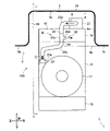
- FIG. 1 is a schematic view of the left side view of the blow-by gas processing apparatus, and is a cross-sectional view taken along the line II of FIG.
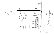
- FIG. 2 is a schematic rear view of the blow-by gas processing apparatus, and is a cross-sectional view taken along the line II-II of FIG.
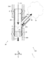
- FIG. 3 is an enlarged cross-sectional view of the blow-by gas pipe shown in Part III of FIG.
- FIG. 4 is an enlarged cross-sectional view taken along the line IV-IV of FIG.
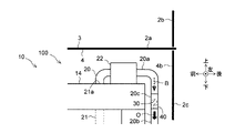
- FIG. 5 is a partial schematic view of the left side view showing the blow-by gas processing apparatus of the first modification.
- FIG. 6 is a partial schematic view of the left side view showing the blow-by gas processing apparatus of the second modification.
- FIG. 1 is a schematic view of the left side view of the blow-by gas processing apparatus, and is a cross-sectional view taken along the line II of FIG.
- FIG. 2 is a schematic rear view of the blow-by gas processing apparatus, and is a
- FIG. 7 is an enlarged cross-sectional view showing a blow-by gas pipe of the third modification.
- FIG. 8 is a schematic view showing the rear portion of the floor surface of the cab of the fourth modification.
- FIG. 9 is a schematic view showing the rear part of the floor surface of the cab of the fifth modification.
- FIG. 10 is a schematic view of the left side view showing the blow-by gas processing apparatus of the sixth modification.
- FIGS. 1 and 2 Each of the up, down, front, back, left, and right directions shown in the figure coincides with each direction of the vehicle 1, although it is only defined for convenience of explanation.
- the vehicle 1 is a cab-over type vehicle (truck in this embodiment), and is provided with a recess 4 recessed upward in the rear portion of the floor surface 3 of the cab 2.
- the upper portion of the internal combustion engine 10 is housed in the recess 4.
- the cab 2 includes a floor panel 2a constituting the floor surface 3 and a back panel 2b extending upward from the rear end position of the floor panel 2a.
- the recess 4 is formed by denting the central portion in the left-right direction in the rear portion of the floor panel 2a upward. Further, the recess 4 is formed in a U-shaped cross section in the left side view (FIG. 1) and the rear view (FIG. 2), respectively.
- the recess 4 of the present embodiment includes a ceiling wall 4a extending in the front-rear direction and a rear side wall 4b extending downward from the position of the rear end portion of the ceiling wall 4a.
- the recess 4 has a front side wall 4c extending downward from the position of the front end portion of the ceiling wall 4a, a left side wall 4d extending downward from the position of the left end portion of the ceiling wall 4a, and a position of the right end portion of the ceiling wall 4a. It is provided with a right side wall 4e extending downward from the ceiling.
- reference numeral 5a indicates a front end portion of the floor panel 2a extending forward from the lower end position of the front side wall 4c. Further, in FIG.
- reference numeral 5b indicates the left end portion of the floor panel 2a extending to the left from the lower end position of the left side wall 4d
- reference numeral 5c indicates the right end of the floor panel 2a extending to the right from the lower end position of the right side wall 4e. Shows the part.
- the internal combustion engine 10 is a multi-cylinder compression ignition type internal combustion engine mounted on the vehicle 1, for example, a diesel engine.
- the internal combustion engine 10 may be of any type, type, application, etc., and may be, for example, a spark ignition type internal combustion engine such as a gasoline engine.
- the internal combustion engine 10 includes a cylinder block 11, a crankcase 12 integrally formed at the lower end of the cylinder block 11, a cylinder head 13 connected to the upper end of the cylinder block 11, and a cylinder head 13.
- a head cover 14 connected to the upper end and an oil pan 15 connected to the lower end of the crankcase 11 are provided.
- the internal combustion engine 10 includes a gear housing 16 connected to the rear wall of each of the cylinder block 11, the crankcase 12, and the cylinder head 13, and a flywheel housing 17 connected to the rear wall of the lower portion of the gear housing 16.
- the upper ends of the cylinder head 13 and the gear housing 16 are covered from above by the head cover 14.
- the lower ends of the crankcase 12 and the gear housing 16 are covered from below by the oil pan 15.
- the cylinder block 11 is provided with a plurality of cylinders, and the cylinders accommodate pistons.
- a crankshaft extending in the front-rear direction is rotatably supported on the crankcase 12, and a valve operating mechanism such as a camshaft is attached to the cylinder head 13.
- a plurality of gears meshed with each other are housed in the gear housing 16, and the flywheel is housed in the flywheel housing 17.
- the upper portion of the internal combustion engine 10 (in the present embodiment, the entire head cover 14, the upper portion of the cylinder head 13, and the upper end portion of the gear housing 16) is the ceiling wall 4a and the side walls 4b to 4e. It is housed in the recess 4 at intervals from the ceiling.
- the blow-by gas processing apparatus 100 of the present embodiment will be described with reference to FIGS. 1 to 4.
- the dotted arrow B indicates the flow of blow-by gas
- the black-painted arrow O indicates the flow of oil.
- the blow-by gas processing device 100 includes a blow-by gas pipe 20 through which blow-by gas B flows.
- blow-by gas is gas that leaks into the crankcase 12 from the gap between the cylinder and the piston.
- the blow-by gas pipe 20 is exposed to the outside of the internal combustion engine 10. On the other hand, inside the internal combustion engine 10, an engine passage 21 through which blow-by gas B flows is provided.
- the engine passage 21 passes from the inside of the crankcase 12 through the inside of the cylinder block 11 and the cylinder head 13 and extends into the head cover 14.
- An outlet 21a of the passage 21 in the engine is formed on the upper surface of the head cover 14.
- the upstream end of the blow-by gas pipe 20 is connected to the outlet 21a of the passage 21 in the engine.
- the blow-by gas pipe 20 of the present embodiment is arranged so as to extend from the upper side to the lower side, and the lower end portion 20e of the blow-by gas pipe 20 is opened to the atmosphere. Specifically, the blow-by gas pipe 20 extends rearward from the outlet 21a of the engine passage 21 along the upper surface portion of the head cover 14, and then is bent downward and extends downward along the rear wall of the head cover 14. ..
- the lower end 20e of the blow-by gas pipe 20 is arranged outside the recess 4. On the other hand, most of the blow-by gas pipe 20 other than the lower end 20e is arranged in the recess 4.
- blow-by gas pipe 20 has an outlet portion 30 opened to the atmosphere in the recess 4.
- the outlet portion 30 is provided at a position in the middle of the blow-by gas pipe 20.
- the blow-by gas pipe 20 connects the upstream pipe 20a located on the upstream side, the downstream pipe 20b located on the downstream side, the upstream pipe 20a and the downstream pipe 20b in the flow direction of the blow-by gas B. It has a connecting pipe 20c and a branch pipe 20d branched from the connecting pipe.
- the upstream pipe 20a and the downstream pipe 20b are made of a resin material such as rubber.
- the connecting pipe 20c and the branch pipe 20d are made of a metal material such as iron.
- An oil separator 22 for removing oil from the blow-by gas B is provided in the middle of the upstream pipe 20a.
- the oil separator 22 is installed on the upper surface of the head cover 14.
- oil is separated from the blow-by gas B introduced therein.
- the oil separated from the blow-by gas B is returned into the crankcase 12 through an oil return passage (not shown).
- the upstream pipe 20a and the connecting pipe 20c located on the downstream side of the oil separator 22 extend downward in order along the rear wall of the head cover 14.
- the downstream pipe 20c extends downward along the rear wall of the gear housing 16.
- the lower end portion 20e of the downstream pipe 20c is arranged at a position below the rear side wall 4b of the recess 4 (in this embodiment, above and near the left side of the flywheel housing 17).
- An oil catch tank 23 for collecting oil O is provided at the lower end portion 20e of the downstream pipe 20c. However, the oil catch tank 23 may not be provided.
- the connecting pipe 20c and the branch pipe 20d are integrally formed and have a T-shaped cross-sectional shape as a whole.
- the alternate long and short dash line C1 indicates the central axis of the connecting pipe 20c
- the alternate long and short dash line C2 indicates the central axis of the branch pipe 20d.
- the connecting pipe 20c extends linearly from above to below.
- the upper end of the connecting pipe 20c is fitted and connected to the inside of the lower end of the upstream pipe 20a, and the lower end of the connecting pipe 20c is fitted and connected to the inside of the upper end of the downstream pipe 20b.
- the upper end portion and the lower end portion of the connecting pipe 20c have a convex portion X formed on the outer peripheral portion thereof.
- the convex portion X is formed by increasing the outer diameter and inner diameter of the connecting pipe 20c by bulge processing or the like, and is formed in an annular shape extending in the circumferential direction and making one round.
- the lower end of the upstream pipe 20a and the upper end of the downstream pipe 20b are fixed in close contact with the convex portion X so as not to come off from the connecting pipe 20c.
- the branch pipe 20d projects to the right from the axially intermediate portion of the connecting pipe 20c and extends.
- the outlet portion 30 of the present embodiment is formed by a branch pipe 20d.
- the outlet portion 30 is arranged between the upper portion of the internal combustion engine 10 (here, the rear wall of the head cover 14) and the rear side wall 4b of the recess 4.
- outlet portion 30 is directed so as to discharge the blow-by gas B toward the surface direction of the rear side wall 4b of the recess 4. That is, the branch pipe 20d extends linearly along the rear side wall 4b of the recess 4.
- the outlet portion 30 is oriented so as to discharge the blow-by gas B in the horizontal direction. That is, the branch pipe 20d extends horizontally from the axially intermediate portion of the connecting pipe 20c.
- the flow path cross-section S1 of the outlet portion 30 is set to be larger than the minimum flow path cross-section S2 of the blow-by gas pipe 20 located on the downstream side of the outlet portion 30.
- the blow-by gas processing device 100 of the present embodiment includes a ring member 40 fitted inside the blow-by gas pipe 20 located on the downstream side of the outlet portion 30.
- the minimum flow path cross-sectional area S2 of the present embodiment is the flow path cross-sectional area of the orifice 41 provided at the center of the ring member 40.
- the orifice 41 substantially narrows the flow path of the blow-by gas pipe 20.
- the ring member 40 of the present embodiment is made of a metal material such as iron and is arranged inside the lower end portion of the connecting pipe 20c. Further, the outer peripheral portion of the ring member 40 is joined to and fixed to the inner peripheral portion of the connecting pipe 20c by welding or the like. However, the ring member 40 may be formed of a resin material such as plastic or rubber, or may be fixed by being press-fitted into the inner peripheral portion of the connecting pipe 20c, for example.
- the blow-by gas B in the crankcase 12 flows through the in-engine passage 21 and the upstream pipe 20a of the blow-by gas pipe 20 in order, and is a connecting pipe. Introduced in 20c.
- the blow-by gas B introduced into the connecting pipe 20c is released to the atmosphere from the outlet portion 30, flows through the downstream pipe 20b, and is released to the atmosphere from the downstream end 20e.
- the flow path cross-sectional area S1 of the outlet portion 30 is set to be larger than the minimum flow path cross-section S2 of the blow-by gas pipe 20 located on the downstream side of the outlet portion 30. Most of the blow-by gas B introduced into the connecting pipe 20c is released to the atmosphere from the outlet portion 30.
- the outlet portion 30 of the present embodiment is arranged in the recess 4. Therefore, even when white smoke W is generated around the outlet portion 30 due to the moisture or oil content in the blow-by gas B, the white smoke is generated by the side wall of the recess 4 (particularly, in the present embodiment, the rear side wall 4b). Can be obscured.
- the white smoke generated around the outlet portion 30 can be made difficult to see from the outside of the vehicle 1.
- the white smoke W generated around the outlet portion 30 collides with the blow-by gas B together with the rear side wall 4b and is turned downward, and flows under the rear side wall 4b to the rear of the cab 2. Therefore, it may be visible from the outside of the vehicle 1.
- the outlet portion 30 of the present embodiment is directed so as to discharge the blow-by gas B toward the surface direction of the rear side wall 4b of the recess 4. Therefore, it is possible to prevent the white smoke W from colliding with the rear side wall 4b and being turned downward and flowing under the rear side wall 4b to the rear of the cab 2. As a result, it is possible to suppress the white smoke W from being seen from the outside of the vehicle 1.
- the white smoke W generated around the outlet portion 30 can be seen from the outside of the vehicle 1 by being flowed downward together with the blow-by gas B, passing through the rear side wall 4b and flowing behind the cab 2. There is sex.
- the outlet portion 30 of the present embodiment is oriented so as to discharge the blow-by gas B in the horizontal direction. Therefore, it is possible to prevent the white smoke W from flowing downward and flowing behind the cab 2 under the rear side wall 4b. As a result, it is possible to suppress the white smoke W from being seen from the outside of the vehicle 1.
- the flow path cross-sectional area S1 of the outlet portion 30 is set to be larger than the minimum flow path cross-sectional area S2 of the blow-by gas pipe 20 located on the downstream side of the outlet portion 30. Therefore, most of the blow-by gas B is discharged from the outlet portion 30. As a result, the discharge of blow-by gas B from the lower end portion 20e of the blow-by gas pipe 20 can be suppressed. As a result, it is possible to suppress the generation of white smoke around the lower end portion 20e, and it is possible to suppress the white smoke from being seen from the outside of the vehicle 1.
- the orifice 41 having the minimum flow path cross-sectional area S2 can be easily formed by simply fitting the ring member 40 inside the blow-by gas pipe 20 located on the downstream side of the outlet portion 30. Can be provided in.
- the blow-by gas pipe 20 is arranged so as to extend from the upper side to the lower side, and the outlet portion 30 is provided at a position in the middle of the blow-by gas pipe 20. Therefore, the oil O that cannot be completely separated by the oil separator 22 and remains in the blow-by gas B adheres to the inside of the blow-by gas pipe 20 and flows down the inside of the blow-by gas pipe 20 to be discharged from the lower end portion 20e. As a result, the discharge of oil O from the outlet portion 30 can be suppressed. Further, the oil O discharged from the lower end portion 20e can be collected by the oil catch tank 23.
- the present disclosure can be a modification or a combination thereof as follows in addition to the above-mentioned first modification and second modification.
- the outlet portion 30 of the third modification is directed so as to discharge the blow-by gas B upward from the horizontal direction.
- the branch pipe 20d of the third modification extends from the intermediate portion in the axial direction of the connecting pipe 20c so as to be inclined upward with respect to the horizontal direction.
- the white smoke W generated around the outlet portion 30 can be flowed diagonally upward together with the blow-by gas B. As a result, it is possible to reliably suppress the white smoke W from going under the rear side wall 2b and being seen from the outside of the vehicle 1.
- the oil O in the blow-by gas B adheres to the branch pipe 20d the oil O flows down the branch pipe 20d and is introduced into the connecting pipe 20c. As a result, it is possible to suppress the oil O from being discharged from the outlet portion 30.
- the rear side wall 4b of the recess 4 may be provided as a separate body from the floor panel 2a. Specifically, the rear end portion of the floor panel 2a of the fourth modification is terminated in a horizontal state, and the rear side wall 4b of the recess 4 is attached to the rear end portion of the floor panel 2a and hung down. It is formed by the cover member 2c. The rear end of the recess 4 is closed by the cover member 2c.
- the rear end portion of the floor panel 2a of the fifth modification is terminated in a horizontal state and connected to the front surface of the back panel 2b.
- the lower end of the back panel 2b extends below the rear end of the floor panel 2a to form the rear side wall 4b of the recess 4.
- the rear end of the recess 4 is closed by the lower end of the back panel 2b.
- the outlet portion 30 may be arranged at an arbitrary position in the recess 4.
- the outlet portion 30 of the sixth modification is arranged between the upper portion of the internal combustion engine 1 (here, the front wall of the head cover 14) and the front side wall 4c of the recess 4, and blow-by gas is directed toward the surface of the front side wall 4c. Directed to eject B.
- the white smoke generated around the outlet portion 30 can be covered with the front side wall 4c of the recess 4. Further, in the sixth modification, the white smoke can be made difficult to see from the outside of the vehicle 1 without providing the rear side wall 4b of the recess 4.
- the outlet portion 30 can be arranged, for example, between the upper portion of the internal combustion engine 1 (here, the left side wall of the head cover 14) and the left side wall surface 4d of the recess 4.
- the blow-by gas pipe 20 may not be provided with the branch pipe 20d.
- the outlet portion 30 is formed by a simple hole formed in the side wall portion of the connecting pipe 20c.
- blow-by gas pipe 20 does not have to be provided with the downstream pipe 20b and the connecting pipe 20c.
- the outlet portion 30 is formed by the lower end portion of the upstream pipe 20a or by a hole provided in the side wall portion of the upstream pipe 20a.
- the blow-by gas pipe 20 may be formed of any material, and the upstream pipe 20a, the downstream pipe 20b, the connecting pipe 20c, and the branch pipe 20d may be integrally formed.
- the blow-by gas treatment apparatus can be widely applied to a technique for making white smoke generated around the outlet portion difficult to see from the outside of the vehicle due to moisture or the like in the blow-by gas.
Landscapes
- Engineering & Computer Science (AREA)
- Mechanical Engineering (AREA)
- General Engineering & Computer Science (AREA)
- Lubrication Details And Ventilation Of Internal Combustion Engines (AREA)
Abstract
キャブオーバ型の車両1の内燃機関10に用いられるブローバイガス処理装置100であって、車両1は、キャブ2の床面3の後部に、上方に凹んだ凹部4を備え、内燃機関10の上部は、凹部4内に収容され、ブローバイガス処理装置100は、ブローバイガスBが流れるブローバイガス管20を備え、ブローバイガス管20は、凹部4内で大気開放された出口部30を有する。
Description
本開示は、ブローバイガス処理装置に関する。
内燃機関においては、ピストンとシリンダの隙間からクランクケース内に漏出したブローバイガスを、ブローバイガス管から大気開放するブローバイガス処理装置が公知である。
トラック等のキャブオーバ型車両では、キャブの床面の後部に上方に凹んだ凹部が設けられ、この凹部には、内燃機関の上部が収容される。一方、ブローバイガス管の出口部は、この凹部よりも下方に配置される。
ところで、上記のブローバイガス処理装置では、ブローバイガス中の水分やオイル分に起因して、ブローバイガス管の出口部の周辺で白煙が発生する場合がある。この場合、車両の外部から白煙が見えると、その白煙の原因が内燃機関の異常であると誤認される可能性があり、不必要な整備につながる虞がある。
本開示の目的は、ブローバイガス中の水分等に起因して出口部の周辺で発生した白煙を、車両の外部から見え難くできるブローバイガス処理装置を提供することである。
本開示の一態様のブローバイガス処理装置は、キャブオーバ型の車両の内燃機関に用いられるブローバイガス処理装置であって、前記車両は、キャブの床面の後部に、上方に凹んだ凹部を備え、前記内燃機関の上部は、前記凹部内に収容され、前記ブローバイガス処理装置は、ブローバイガスが流れるブローバイガス管を備え、前記ブローバイガス管は、前記凹部内で大気開放された出口部を有する。
好ましくは、前記出口部は、前記凹部の側壁の面方向に向かってブローバイガスを排出するように指向される。
また、前記出口部は、水平方向または水平方向よりも上方に向かってブローバイガスを排出するように指向される。
また、前記ブローバイガス管は、上方から下方に向かって延びるように配置され、前記ブローバイガス管の下端部は、大気開放され、前記出口部は、前記ブローバイガス管の途中の位置に設けられる。
また、前記出口部の流路断面積は、前記出口部よりも下流側に位置する前記ブローバイガス管の最小流路断面積よりも大きい。
また、ブローバイガス処理装置は、前記出口部よりも下流側に位置する前記ブローバイガス管の内側に嵌合されたリング部材を更に備え、前記最小流路断面積は、前記リング部材の中心部に設けられたオリフィスの流路断面積である。
また、前記凹部は、前後方向に延びる天井壁と、前記天井壁の後端部の位置から下方に延びる後側側壁と、を備え、前記出口部は、前記内燃機関の上部と前記後側側壁との間に配置される。
本開示のブローバイガス処理装置によれば、ブローバイガス中の水分等に起因して出口部の周辺で発生した白煙を、車両の外部から見え難くできる。
以下、添付図面を参照して本開示の実施形態を説明する。なお、本開示は以下の実施形態に限定されない点に留意されたい。
先ず、図1及び図2を参照して、車両1に用いられる内燃機関10の構成を説明する。図中に示す上下前後左右の各方向は、説明の便宜上定められたものに過ぎないが、車両1の各方向と一致する。
図1に示すように、車両1は、キャブオーバ型車両(本実施形態では、トラック)であり、キャブ2の床面3の後部に上方に凹んだ凹部4を備える。内燃機関10の上部は、凹部4内に収容される。
キャブ2は、床面3を構成するフロアパネル2aと、フロアパネル2aの後端位置から上方に延びるバックパネル2bと、を備える。
図1及び図2に示すように、凹部4は、フロアパネル2aの後部における左右方向の中央部分を上方に凹ませて形成される。また、凹部4は、左側面視(図1)及び後面視(図2)において断面コ字状にそれぞれ形成される。
本実施形態の凹部4は、前後方向に延びる天井壁4aと、天井壁4aの後端部の位置から下方に延びる後側側壁4bと、を備える。
また、凹部4は、天井壁4aの前端部の位置から下方に延びる前側側壁4cと、天井壁4aの左側端部の位置から下方に延びる左側側壁4dと、天井壁4aの右側端部の位置から下方に延びる右側側壁4eと、を備える。なお、図1中、符号5aは、前側側壁4cの下端位置から前方に延びるフロアパネル2aの前側端部を示す。また、図2中、符号5bは、左側側壁4dの下端位置から左側に延びるフロアパネル2aの左側端部を示し、符号5cは、右側側壁4eの下端位置から右側に延びるフロアパネル2aの右側端部を示す。
内燃機関10は、車両1に搭載された多気筒の圧縮着火式内燃機関、例えばディーゼルエンジンである。但し、内燃機関10は、任意の種類、形式、用途等であって良く、例えば、ガソリンエンジン等の火花点火式内燃機関であっても良い。
図1に示すように、内燃機関10は、シリンダブロック11と、シリンダブロック11の下端に一体形成されたクランクケース12と、シリンダブロック11の上端に接続されたシリンダヘッド13と、シリンダヘッド13の上端に接続されたヘッドカバー14と、クランクケース11の下端に接続されたオイルパン15と、を備える。
また、内燃機関10は、シリンダブロック11、クランクケース12、及びシリンダヘッド13のそれぞれの後壁に接続されたギアハウジング16と、ギアハウジング16の下部の後壁に接続されたフライホイールハウジング17と、を備える。
シリンダヘッド13及びギアハウジング16の上端は、ヘッドカバー14によって上側から覆われる。一方、クランクケース12及びギアハウジング16の下端は、オイルパン15によって下側から覆われる。
図示しないが、シリンダブロック11には、複数のシリンダが設けられ、シリンダには、ピストンが収容される。クランクケース12には、前後方向に延びるクランクシャフトが回転可能に支持され、シリンダヘッド13には、カムシャフト等の動弁機構が取り付けられる。ギアハウジング16には、互いに噛合された複数のギアが収容され、フライホイールハウジング17には、フライホイールが収容される。
図1及び図2に示すように、内燃機関10の上部(本実施形態では、ヘッドカバー14の全体、シリンダヘッド13の上部、及びギアハウジング16の上端部)は、天井壁4a及び側壁4b~4eから間隔を空けて凹部4内に収容される。
次に、図1~図4を参照して、本実施形態のブローバイガス処理装置100を説明する。図中、点線矢印Bは、ブローバイガスの流れを示し、黒塗り矢印Oは、オイルの流れを示す。
図1に示すように、ブローバイガス処理装置100は、ブローバイガスBが流れるブローバイガス管20を備える。周知のように、ブローバイガスは、シリンダとピストンとの隙間からクランクケース12内に漏れ出たガスである。
ブローバイガス管20は、内燃機関10の外部に露出される。一方、内燃機関10の内部には、ブローバイガスBが流れるエンジン内通路21が設けられる。
エンジン内通路21は、クランクケース12内からシリンダブロック11及びシリンダヘッド13の内部を通過してヘッドカバー14内に延びる。ヘッドカバー14の上面部には、エンジン内通路21の出口21aが形成される。エンジン内通路21の出口21aには、ブローバイガス管20の上流端が接続される。
本実施形態のブローバイガス管20は、上方から下方に向かって延びるように配置され、ブローバイガス管20の下端部20eは、大気開放される。具体的には、ブローバイガス管20は、エンジン内通路21の出口21aからヘッドカバー14の上面部に沿って後方に延びた後、下側に曲げられてヘッドカバー14の後壁に沿って下方に延びる。
ブローバイガス管20の下端部20eは、凹部4外に配置される。一方、下端部20e以外のブローバイガス管20の大体の部分は、凹部4内に配置される。
また、ブローバイガス管20は、凹部4内で大気開放された出口部30を有する。出口部30は、ブローバイガス管20の途中の位置に設けられる。
図2に示すように、ブローバイガス管20は、ブローバイガスBの流れ方向において、上流側に位置する上流管20aと、下流側に位置する下流管20bと、上流管20a及び下流管20bを接続する接続管20cと、接続管から分岐された分岐管20dと、を有する。
上流管20a及び下流管20bは、ゴム等の樹脂材料で形成される。一方、接続管20c及び分岐管20dは、鉄等の金属材料で形成される。
上流管20aの途中には、ブローバイガスBからオイルを除去するためのオイルセパレータ22が設けられる。オイルセパレータ22は、ヘッドカバー14の上面部に設置される。
オイルセパレータ22では、これに導入されたブローバイガスBからオイルが分離される。ブローバイガスBから分離されたオイルは、オイル戻り通路(不図示)を通じてクランクケース12内に戻される。
オイルセパレータ22よりも下流側に位置する上流管20a、及び接続管20cは、ヘッドカバー14の後壁に沿って順に下方に延びる。下流管20cは、ギアハウジング16の後壁に沿って下方に延びる。
下流管20cの下端部20eは、凹部4の後側側壁4bよりも下方の位置(本実施形態では、フライホイールハウジング17の左側上方かつ近傍の位置)に配置される。下流管20cの下端部20eには、オイルOを捕集するためのオイルキャッチタンク23が設けられる。但し、オイルキャッチタンク23は設けなくても良い。
図3に示すように、接続管20c及び分岐管20dは、一体的に形成され、全体としてT字状の断面形状を有する。図3中、一点鎖線C1は、接続管20cの中心軸を示し、一点鎖線C2は、分岐管20dの中心軸を示す。
接続管20cは、上方から下方に向かって直線状に延びる。接続管20cの上端部は、上流管20aの下端部の内側に嵌合されて接続され、接続管20cの下端部は、下流管20bの上端部の内側に嵌合されて接続される。
また、接続管20cの上端部及び下端部は、その外周部に形成された凸部Xを有する。凸部Xは、バルジ加工等により接続管20cの外径及び内径を拡径させてなり、周方向に延びて1周する環状に形成される。上流管20aの下端部及び下流管20bの上端部は、凸部Xに密着して固定されることで、接続管20cから抜けないように抜け止めされる。
分岐管20dは、接続管20cの軸方向の中間部分から右方向に突出して延びる。本実施形態の出口部30は、分岐管20dによって形成される。
図4に示すように、出口部30は、内燃機関10の上部(ここでは、ヘッドカバー14の後壁)と凹部4の後側側壁4bとの間に配置される。
また、出口部30は、凹部4の後側側壁4bの面方向に向かってブローバイガスBを排出するように指向される。すなわち、分岐管20dは、凹部4の後側側壁4bに沿って直線状に延びる。
また、図3に示すように、出口部30は、水平方向に向かってブローバイガスBを排出するように指向される。すなわち、分岐管20dは、接続管20cの軸方向の中間部分から水平方向に延びる。
出口部30の流路断面積S1は、出口部30よりも下流側に位置するブローバイガス管20の最小流路断面積S2よりも大きく設定される。
具体的には、本実施形態のブローバイガス処理装置100は、出口部30よりも下流側に位置するブローバイガス管20の内側に嵌合されたリング部材40を備える。本実施形態の最小流路断面積S2は、リング部材40の中心部に設けられたオリフィス41の流路断面積である。オリフィス41は、実質的にブローバイガス管20の流路を絞る。
本実施形態のリング部材40は、鉄等の金属材料で形成され、接続管20cの下端部の内側に配置される。また、リング部材40の外周部は、溶接等によって接続管20cの内周部に接合されて固定される。但し、リング部材40は、プラスチックやゴム等の樹脂材料で形成されても良く、また、例えば、接続管20cの内周部に圧入されて固定されても良い。
図1に示したように、本実施形態では、内燃機関10の稼働中、クランクケース12内のブローバイガスBが、エンジン内通路21及びブローバイガス管20の上流管20aを順に流れて、接続管20cに導入される。接続管20cに導入されたブローバイガスBは、出口部30から大気開放されると共に、下流管20bを流れて下流端20eから大気開放される。
但し、図3に示したように、出口部30の流路断面積S1は、出口部30よりも下流側に位置するブローバイガス管20の最小流路断面積S2よりも大きく設定されているので、接続管20cに導入されたブローバイガスBの大部分は、出口部30から大気開放される。
また、図1及び図4に示したように、本実施形態の出口部30は、凹部4内に配置される。そのため、ブローバイガスB中の水分やオイル分に起因して出口部30の周辺で白煙Wが発生した場合でも、凹部4の側壁(特に、本実施形態では、後側側壁4b)によって白煙を覆い隠すことができる。
よって、本実施形態のブローバイガス処理装置100であれば、出口部30の周辺で発生した白煙を、車両1の外部から見え難くできる。その結果、白煙の原因が内燃機関10の異常であると誤認して、不必要な整備が行われるのを抑制できる。
また、本実施形態では、上記以外に、下記の(1)~(6)のような作用効果も存在する。下記の(1)及び(2)では、変形例と比較して本実施形態の作用効果を説明する。これらの変形例では、上記の実施形態と同一または共通する構成要素に同じ符号を用い、それらの詳細な説明は省略する。
(1)図5に示すように、本実施形態の変形例としては、出口部30が凹部4の後側側壁4bに向かってブローバイガスBを排出するように指向された第1変形例が考えられる。
しかしながら、この場合、出口部30の周辺で発生した白煙Wが、ブローバイガスBと共に後側側壁4bに衝突して下方に方向転換され、後側側壁4bを潜ってキャブ2の後方に流されて、車両1の外部から見える可能性がある。
これに対して、図4に示したように、本実施形態の出口部30は、凹部4の後側側壁4bの面方向に向かってブローバイガスBを排出するように指向される。そのため、白煙Wが後側側壁4bに衝突して下方に方向転換され、後側側壁4bを潜ってキャブ2の後方に流されるのを抑制できる。その結果、白煙Wが車両1の外部から見えるのを抑制できる。
(2)図6に示すように、本実施形態の変形例としては、出口部30が水平方向よりも下方に向かってブローバイガスBを排出するように指向された第2変形例が考えられる。
しかしながら、この場合、出口部30の周辺で発生した白煙Wが、ブローバイガスBと共に下方に流され、後側側壁4bを潜ってキャブ2の後方に流されて、車両1の外部から見える可能性がある。
これに対して、図3に示したように、本実施形態の出口部30は、水平方向に向かってブローバイガスBを排出するように指向される。そのため、白煙Wが下方に流されて、後側側壁4bを潜ってキャブ2の後方に流されるのを抑制できる。その結果、白煙Wが車両1の外部から見えるのを抑制できる。
(3)前述した通り、本実施形態では、出口部30の流路断面積S1が、出口部30よりも下流側に位置するブローバイガス管20の最小流路断面積S2よりも大きく設定されるので、ブローバイガスBの大部分が出口部30から排出される。これにより、ブローバイガス管20の下端部20eからのブローバイガスBの排出を抑制できる。その結果、下端部20eの周辺で白煙が発生するのを抑制でき、その白煙が車両1の外部から見えるのを抑制できる。
(4)また、本実施形態では、出口部30よりも下流側に位置するブローバイガス管20の内側に、リング部材40を嵌合させるだけで、最小流路断面積S2となるオリフィス41を簡単に設けることができる。
(5)本実施形態では、図1に示したように、ブローバイガス管20が上方から下方に向かって延びるように配置され、出口部30は、ブローバイガス管20の途中の位置に設けられる。そのため、オイルセパレータ22で分離し切れずにブローバイガスBに残留したオイルOは、ブローバイガス管20内に付着して、ブローバイガス管20内を流下することで、下端部20eから排出される。これにより、出口部30からのオイルOの排出を抑制できる。また、下端部20eから排出されたオイルOは、オイルキャッチタンク23で捕集できる。
(6)出口部30よりも下流側に位置するブローバイガス管20内では、リング部材40によってブローバイガスBの流れが妨げられる。これにより、リング部材40の上端面やその周辺のブローバイガス管20の内壁に、ブローバイガスB中のオイルを積極的に付着させて、ブローバイガスB中のオイル分を減少させることができる。その結果、出口部30の周辺での白煙の発生を抑制できる。
以上、本開示の実施形態を詳細に述べたが、本開示は、上記の第1変形例及び第2変形例の他にも、以下のような変形例またはその組み合わせとすることができる。
(第3変形例)
図7に示すように、第3変形例の出口部30は、水平方向よりも上方に向かってブローバイガスBを排出するように指向される。具体的には、第3変形例の分岐管20dは、接続管20cの軸方向の中間部分から水平方向に対して上方に傾斜して延びる。
図7に示すように、第3変形例の出口部30は、水平方向よりも上方に向かってブローバイガスBを排出するように指向される。具体的には、第3変形例の分岐管20dは、接続管20cの軸方向の中間部分から水平方向に対して上方に傾斜して延びる。
第3変形例によれば、出口部30の周辺で発生した白煙Wを、ブローバイガスBと共に斜め上方に向かって流すことができる。これにより、白煙Wが後側側壁2bを潜って車両1の外部から見えるのを確実に抑制できる。
また、第3変形例であれば、分岐管20d内にブローバイガスB中のオイルOが付着した場合に、このオイルOが分岐管20d内を流下して接続管20c内に導入される。これにより、出口部30からオイルOが排出されるのを抑制できる。
(第4変形例)
図8に示すように、凹部4の後側側壁4bは、フロアパネル2aとは別体として設けられても良い。具体的には、第4変形例のフロアパネル2aの後端部は、水平な状態で終端されており、凹部4の後側側壁4bは、フロアパネル2aの後端部に取り付けられて垂下されたカバー部材2cによって形成される。凹部4の後端は、カバー部材2cによって閉じられる。
図8に示すように、凹部4の後側側壁4bは、フロアパネル2aとは別体として設けられても良い。具体的には、第4変形例のフロアパネル2aの後端部は、水平な状態で終端されており、凹部4の後側側壁4bは、フロアパネル2aの後端部に取り付けられて垂下されたカバー部材2cによって形成される。凹部4の後端は、カバー部材2cによって閉じられる。
(第5変形例)
図9に示すように、第5変形例のフロアパネル2aの後端部は、水平な状態で終端され、バックパネル2bの前面に接続される。バックパネル2bの下端部は、フロアパネル2aの後端部よりも下方に延在し、凹部4の後側側壁4bを形成する。凹部4の後端は、バックパネル2bの下端部によって閉じられる。
図9に示すように、第5変形例のフロアパネル2aの後端部は、水平な状態で終端され、バックパネル2bの前面に接続される。バックパネル2bの下端部は、フロアパネル2aの後端部よりも下方に延在し、凹部4の後側側壁4bを形成する。凹部4の後端は、バックパネル2bの下端部によって閉じられる。
(第6変形例)
図10に示すように、出口部30は、凹部4内の任意の位置に配置されて良い。第6変形例の出口部30は、内燃機関1の上部(ここでは、ヘッドカバー14の前壁)と凹部4の前側側壁4cとの間に配置され、前側側壁4cの面方向に向かってブローバイガスBを排出するように指向される。
図10に示すように、出口部30は、凹部4内の任意の位置に配置されて良い。第6変形例の出口部30は、内燃機関1の上部(ここでは、ヘッドカバー14の前壁)と凹部4の前側側壁4cとの間に配置され、前側側壁4cの面方向に向かってブローバイガスBを排出するように指向される。
第6変形例によれば、出口部30の周辺で発生した白煙を、凹部4の前側側壁4cで覆い隠すことができる。また、第6変形例であれば、凹部4の後側側壁4bを設けなくても、車両1の外部から白煙を見え難くできる。
なお、図示しないが、出口部30は、例えば、内燃機関1の上部(ここでは、ヘッドカバー14の左側壁)と凹部4の左側側壁4dとの間に配置することも可能である。
(第7変形例)
図示しないが、ブローバイガス管20には、分岐管20dが設けられなくても良い。この場合、出口部30は、接続管20cの側壁部に形成された単なる穴によって形成される。
図示しないが、ブローバイガス管20には、分岐管20dが設けられなくても良い。この場合、出口部30は、接続管20cの側壁部に形成された単なる穴によって形成される。
また、ブローバイガス管20には、下流管20b及び接続管20cが設けられなくても良い。この場合、出口部30は、上流管20aの下端部によって形成され、または上流管20aの側壁部に設けられた穴によって形成される。
(第8変形例)
ブローバイガス管20は、任意の材質で形成されて良く、また、上流管20a、下流管20b、接続管20c及び分岐管20dが一体に形成されても良い。
ブローバイガス管20は、任意の材質で形成されて良く、また、上流管20a、下流管20b、接続管20c及び分岐管20dが一体に形成されても良い。
本出願は、2020年9月29日付で出願された日本国特許出願(特願2020-163744)に基づくものであり、その内容はここに参照として取り込まれる。
本開示に係るブローバイガス処理装置は、ブローバイガス中の水分等に起因して出口部の周辺で発生した白煙を、車両の外部から見え難くする技術に広く適用することができる。
1 キャブオーバ型車両
2 キャブ
3 床面
4 凹部
4a 天井壁
4b 後側側壁
10 内燃機関
20 ブローバイガス管
20e 下端部
30 出口部
40 リング部材
41 オリフィス
100 ブローバイガス処理装置
B ブローバイガス
O オイル
2 キャブ
3 床面
4 凹部
4a 天井壁
4b 後側側壁
10 内燃機関
20 ブローバイガス管
20e 下端部
30 出口部
40 リング部材
41 オリフィス
100 ブローバイガス処理装置
B ブローバイガス
O オイル
Claims (7)
- キャブオーバ型の車両の内燃機関に用いられるブローバイガス処理装置であって、
前記車両は、キャブの床面の後部に、上方に凹んだ凹部を備え、
前記内燃機関の上部は、前記凹部内に収容され、
前記ブローバイガス処理装置は、ブローバイガスが流れるブローバイガス管を備え、
前記ブローバイガス管は、前記凹部内で大気開放された出口部を有する
ブローバイガス処理装置。 - 前記出口部は、前記凹部の側壁の面方向に向かってブローバイガスを排出するように指向される
請求項1に記載のブローバイガス処理装置。 - 前記出口部は、水平方向または水平方向よりも上方に向かってブローバイガスを排出するように指向される
請求項1または2に記載のブローバイガス処理装置。 - 前記ブローバイガス管は、上方から下方に向かって延びるように配置され、
前記ブローバイガス管の下端部は、大気開放され、
前記出口部は、前記ブローバイガス管の途中の位置に設けられる
請求項1~3の何れか一項に記載のブローバイガス処理装置。 - 前記出口部の流路断面積は、前記出口部よりも下流側に位置する前記ブローバイガス管の最小流路断面積よりも大きい
請求項4に記載のブローバイガス処理装置。 - 前記出口部よりも下流側に位置する前記ブローバイガス管の内側に嵌合されたリング部材を更に備え、
前記最小流路断面積は、前記リング部材の中心部に設けられたオリフィスの流路断面積である
請求項5に記載のブローバイガス処理装置。 - 前記凹部は、前後方向に延びる天井壁と、前記天井壁の後端部の位置から下方に延びる後側側壁と、を備え、
前記出口部は、前記内燃機関の上部と前記後側側壁との間に配置される
請求項1~6の何れか一項に記載のブローバイガス処理装置。
Applications Claiming Priority (2)
| Application Number | Priority Date | Filing Date | Title |
|---|---|---|---|
| JP2020-163744 | 2020-09-29 | ||
| JP2020163744A JP2022055989A (ja) | 2020-09-29 | 2020-09-29 | ブローバイガス処理装置 |
Publications (1)
| Publication Number | Publication Date |
|---|---|
| WO2022071260A1 true WO2022071260A1 (ja) | 2022-04-07 |
Family
ID=80950391
Family Applications (1)
| Application Number | Title | Priority Date | Filing Date |
|---|---|---|---|
| PCT/JP2021/035494 Ceased WO2022071260A1 (ja) | 2020-09-29 | 2021-09-28 | ブローバイガス処理装置 |
Country Status (2)
| Country | Link |
|---|---|
| JP (1) | JP2022055989A (ja) |
| WO (1) | WO2022071260A1 (ja) |
Citations (9)
| Publication number | Priority date | Publication date | Assignee | Title |
|---|---|---|---|---|
| JPS4944946U (ja) * | 1972-07-27 | 1974-04-19 | ||
| JPS58156112U (ja) * | 1982-04-15 | 1983-10-18 | 株式会社クボタ | 耐転倒内燃機関のブレザ−装置 |
| JPH0359415U (ja) * | 1989-10-16 | 1991-06-12 | ||
| JP2000282838A (ja) * | 1999-03-30 | 2000-10-10 | Suzuki Motor Corp | エンジンのブリーザ構造 |
| JP2003278521A (ja) * | 2002-03-26 | 2003-10-02 | Nissan Diesel Motor Co Ltd | ブローバイガス還元装置 |
| JP2006220120A (ja) * | 2005-02-14 | 2006-08-24 | Shin Caterpillar Mitsubishi Ltd | ブリーザホース構造 |
| JP2007008389A (ja) * | 2005-07-01 | 2007-01-18 | Suzuki Motor Corp | エンジンマウント構造 |
| WO2018210409A1 (en) * | 2017-05-16 | 2018-11-22 | Volvo Truck Corporation | A system for ventilation of a crankcase |
| JP2020023939A (ja) * | 2018-08-08 | 2020-02-13 | いすゞ自動車株式会社 | ブローバイガス大気解放装置 |
-
2020
- 2020-09-29 JP JP2020163744A patent/JP2022055989A/ja active Pending
-
2021
- 2021-09-28 WO PCT/JP2021/035494 patent/WO2022071260A1/ja not_active Ceased
Patent Citations (9)
| Publication number | Priority date | Publication date | Assignee | Title |
|---|---|---|---|---|
| JPS4944946U (ja) * | 1972-07-27 | 1974-04-19 | ||
| JPS58156112U (ja) * | 1982-04-15 | 1983-10-18 | 株式会社クボタ | 耐転倒内燃機関のブレザ−装置 |
| JPH0359415U (ja) * | 1989-10-16 | 1991-06-12 | ||
| JP2000282838A (ja) * | 1999-03-30 | 2000-10-10 | Suzuki Motor Corp | エンジンのブリーザ構造 |
| JP2003278521A (ja) * | 2002-03-26 | 2003-10-02 | Nissan Diesel Motor Co Ltd | ブローバイガス還元装置 |
| JP2006220120A (ja) * | 2005-02-14 | 2006-08-24 | Shin Caterpillar Mitsubishi Ltd | ブリーザホース構造 |
| JP2007008389A (ja) * | 2005-07-01 | 2007-01-18 | Suzuki Motor Corp | エンジンマウント構造 |
| WO2018210409A1 (en) * | 2017-05-16 | 2018-11-22 | Volvo Truck Corporation | A system for ventilation of a crankcase |
| JP2020023939A (ja) * | 2018-08-08 | 2020-02-13 | いすゞ自動車株式会社 | ブローバイガス大気解放装置 |
Also Published As
| Publication number | Publication date |
|---|---|
| JP2022055989A (ja) | 2022-04-08 |
Similar Documents
| Publication | Publication Date | Title |
|---|---|---|
| US8844276B2 (en) | Exhaust muffler for general-purpose engine | |
| JP3281190B2 (ja) | 自動二輪車用内燃機関の排気浄化装置 | |
| US20100018493A1 (en) | Device for Separating Oil From Blow-By Gas | |
| JP5032641B2 (ja) | 車両用エンジン | |
| JP3974333B2 (ja) | 車両用エアクリーナ構造 | |
| JP5238629B2 (ja) | エアクリーナ | |
| US20170074132A1 (en) | Exhaust system for internal combustion engine | |
| JP4240431B2 (ja) | 自動二輪車のエアクリーナ装置 | |
| JP4043825B2 (ja) | 内燃機関のpcv装置 | |
| JP2009203977A (ja) | 内燃機関のブリーザ装置 | |
| JP7810507B2 (ja) | エンジン | |
| JP2022055989A (ja) | ブローバイガス処理装置 | |
| US8413639B2 (en) | Fuel supplying apparatus for internal combustion engine | |
| JP6816582B2 (ja) | 内燃機関の吸気装置 | |
| JP2000087816A (ja) | エンジンの吸気装置 | |
| JP2021004591A (ja) | ブローバイガス処理装置 | |
| JP2018193944A (ja) | 内燃機関のブローバイガス処理装置 | |
| KR20050034791A (ko) | 오일 세퍼레이터 | |
| US6168484B1 (en) | Intake apparatus of outboard motor | |
| JP5162481B2 (ja) | 内燃機関の潤滑装置 | |
| CN1213218C (zh) | 机动二轮车的漏出气体处理装置 | |
| JP6319012B2 (ja) | エンジンのブリーザ室レイアウト構造 | |
| JP2000282838A (ja) | エンジンのブリーザ構造 | |
| JP2854964B2 (ja) | 自動二輪車の吸気装置 | |
| JP7038691B2 (ja) | 内燃機関のヘッドカバー装置 |
Legal Events
| Date | Code | Title | Description |
|---|---|---|---|
| 121 | Ep: the epo has been informed by wipo that ep was designated in this application |
Ref document number: 21875561 Country of ref document: EP Kind code of ref document: A1 |
|
| NENP | Non-entry into the national phase |
Ref country code: DE |
|
| 122 | Ep: pct application non-entry in european phase |
Ref document number: 21875561 Country of ref document: EP Kind code of ref document: A1 |