WO2022071074A1 - バランサ装置 - Google Patents
バランサ装置 Download PDFInfo
- Publication number
- WO2022071074A1 WO2022071074A1 PCT/JP2021/034920 JP2021034920W WO2022071074A1 WO 2022071074 A1 WO2022071074 A1 WO 2022071074A1 JP 2021034920 W JP2021034920 W JP 2021034920W WO 2022071074 A1 WO2022071074 A1 WO 2022071074A1
- Authority
- WO
- WIPO (PCT)
- Prior art keywords
- end plate
- rod
- rear end
- balancer device
- movable member
- Prior art date
- Legal status (The legal status is an assumption and is not a legal conclusion. Google has not performed a legal analysis and makes no representation as to the accuracy of the status listed.)
- Ceased
Links
Images



Classifications
-
- B—PERFORMING OPERATIONS; TRANSPORTING
- B25—HAND TOOLS; PORTABLE POWER-DRIVEN TOOLS; MANIPULATORS
- B25J—MANIPULATORS; CHAMBERS PROVIDED WITH MANIPULATION DEVICES
- B25J19/00—Accessories fitted to manipulators, e.g. for monitoring, for viewing; Safety devices combined with or specially adapted for use in connection with manipulators
- B25J19/0008—Balancing devices
- B25J19/0016—Balancing devices using springs
-
- F—MECHANICAL ENGINEERING; LIGHTING; HEATING; WEAPONS; BLASTING
- F16—ENGINEERING ELEMENTS AND UNITS; GENERAL MEASURES FOR PRODUCING AND MAINTAINING EFFECTIVE FUNCTIONING OF MACHINES OR INSTALLATIONS; THERMAL INSULATION IN GENERAL
- F16F—SPRINGS; SHOCK-ABSORBERS; MEANS FOR DAMPING VIBRATION
- F16F13/00—Units comprising springs of the non-fluid type as well as vibration-dampers, shock-absorbers, or fluid springs
- F16F13/005—Units comprising springs of the non-fluid type as well as vibration-dampers, shock-absorbers, or fluid springs comprising both a wound spring and a damper, e.g. a friction damper
-
- B—PERFORMING OPERATIONS; TRANSPORTING
- B25—HAND TOOLS; PORTABLE POWER-DRIVEN TOOLS; MANIPULATORS
- B25J—MANIPULATORS; CHAMBERS PROVIDED WITH MANIPULATION DEVICES
- B25J19/00—Accessories fitted to manipulators, e.g. for monitoring, for viewing; Safety devices combined with or specially adapted for use in connection with manipulators
- B25J19/0008—Balancing devices
-
- B—PERFORMING OPERATIONS; TRANSPORTING
- B25—HAND TOOLS; PORTABLE POWER-DRIVEN TOOLS; MANIPULATORS
- B25J—MANIPULATORS; CHAMBERS PROVIDED WITH MANIPULATION DEVICES
- B25J9/00—Program-controlled manipulators
- B25J9/0009—Constructional details, e.g. manipulator supports, bases
- B25J9/0018—Bases fixed on ceiling, i.e. upside down manipulators
-
- F—MECHANICAL ENGINEERING; LIGHTING; HEATING; WEAPONS; BLASTING
- F16—ENGINEERING ELEMENTS AND UNITS; GENERAL MEASURES FOR PRODUCING AND MAINTAINING EFFECTIVE FUNCTIONING OF MACHINES OR INSTALLATIONS; THERMAL INSULATION IN GENERAL
- F16F—SPRINGS; SHOCK-ABSORBERS; MEANS FOR DAMPING VIBRATION
- F16F7/00—Vibration-dampers; Shock-absorbers
- F16F7/12—Vibration-dampers; Shock-absorbers using plastic deformation of members
-
- F—MECHANICAL ENGINEERING; LIGHTING; HEATING; WEAPONS; BLASTING
- F16—ENGINEERING ELEMENTS AND UNITS; GENERAL MEASURES FOR PRODUCING AND MAINTAINING EFFECTIVE FUNCTIONING OF MACHINES OR INSTALLATIONS; THERMAL INSULATION IN GENERAL
- F16F—SPRINGS; SHOCK-ABSORBERS; MEANS FOR DAMPING VIBRATION
- F16F7/00—Vibration-dampers; Shock-absorbers
- F16F7/12—Vibration-dampers; Shock-absorbers using plastic deformation of members
- F16F7/125—Units with a telescopic-like action as one member moves into, or out of a second member
-
- F—MECHANICAL ENGINEERING; LIGHTING; HEATING; WEAPONS; BLASTING
- F16—ENGINEERING ELEMENTS AND UNITS; GENERAL MEASURES FOR PRODUCING AND MAINTAINING EFFECTIVE FUNCTIONING OF MACHINES OR INSTALLATIONS; THERMAL INSULATION IN GENERAL
- F16M—FRAMES, CASINGS OR BEDS OF ENGINES, MACHINES OR APPARATUS, NOT SPECIFIC TO ENGINES, MACHINES OR APPARATUS PROVIDED FOR ELSEWHERE; STANDS; SUPPORTS
- F16M2200/00—Details of stands or supports
- F16M2200/04—Balancing means
- F16M2200/044—Balancing means for balancing rotational movement of the undercarriage
Definitions
- a gravity balancer for a robot is known that reduces a load moment due to gravity acting on the first arm of a robot by applying a force in a direction of pushing out from the housing to a rod by a compression coil spring in the housing (for example, Patent Document). See 1.).
- One aspect of the present disclosure is a housing provided with a tubular body portion, a front end plate and a rear end plate that close both ends of the body portion in the axial direction, and the front end plate is penetrated in the plate thickness direction to form the shaft.
- a rod that is movably supported along the direction, a movable member that is fixed to the rod and housed in the housing, a compression coil spring that is arranged between the movable member and the rear end plate, and the shaft.
- It is a balancer device including a connecting member for connecting the rod and the rear end plate with a play larger than the stroke of the rod in the direction.
- FIG. 8 is a vertical cross-sectional view showing a state in which the compression coil spring is most extended in the balancer device of FIG. It is a vertical sectional view which shows the 1st modification of the balancer apparatus of FIG. It is a vertical sectional view which shows the 2nd modification of the balancer apparatus of FIG. It is a vertical sectional view which shows the 3rd modification of the balancer apparatus of FIG. It is a vertical sectional view which shows the 4th modification of the balancer apparatus of FIG.
- the balancer device 100 according to the first embodiment of the present disclosure will be described below with reference to the drawings. As shown in FIG. 1, the balancer device 100 according to the present embodiment is mounted on, for example, a ceiling-mounted robot 1 suspended from the ceiling.
- the ceiling-mounted robot 1 includes a base 2 installed on the ceiling, a swivel cylinder 3 rotatably supported with respect to the base 2 around the first axis J1 extending in the vertical direction, and a second axis J2 extending in the horizontal direction. It is provided with an arm 4 rotatably supported around the swivel cylinder 3.
- the balancer device 100 is arranged between the swivel cylinder 3 and the arm 4.
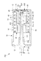
- the balancer device 100 includes a housing 10, a rod 20, a movable member 30, a compression coil spring 40, and a connecting member 50.
- the housing 10 includes a cylindrical body portion 11 and a flat plate-shaped front end plate 12 and a rear end plate 13 that close both ends of the body portion 11 in the direction of the central axis (axis) OL1.
- the front end plate 12 and the rear end plate 13 are fixed to the body portion 11 by, for example, bolts (not shown). Further, either one of the front end plate 12 and the rear end plate 13 may be integrated with the body portion 11.
- a through hole penetrating in the plate thickness direction is provided in the center of the front end plate 12.
- a through hole 13h penetrating in the plate thickness direction is provided in the center of the rear end plate 13, and a plurality of screw holes are provided around the through hole 13h.
- the rod 20 is movably supported by a bearing 12b arranged in a through hole provided in the front end plate 12 in a direction along the central axis OL1 with respect to the housing 10.
- the bearing 12b may be integrated with the front end plate 12 instead of being a separate part.
- a mounting block 21 for attaching the rod 20 to the arm 4 is fixed to one end of the rod 20 arranged outside the housing 10.
- a movable member 30 is fixed to the other end of the rod 20 arranged inside the housing 10.
- the movable member 30 is formed in a disk shape having an outer diameter slightly smaller than the inner diameter of the body portion 11 of the housing 10.
- the rod 20 is formed by a nut fastened to a male screw formed at the other end of the rod 20. It is fixed to the other end.
- the mounting seat surface 51b is provided with a plurality of through holes penetrating in the axial direction of the main body portion 51a. With the main body 51a inserted into the through hole 13h of the rear end plate 13 from the outside, the bolt 15 that penetrates the through hole of the mounting seat surface 51b is fastened to the screw hole of the rear end plate 13 for the first connection. The piece 51 is fixed to the rear end plate 13.
- the second connecting piece 52 has a cylindrical main body portion 52a having an outer diameter capable of penetrating the inner diameter of the stopper 51c, and a radial outer diameter larger than the inner diameter of the stopper 51c from the outer peripheral surface of one end of the main body portion 52a. It is provided with a flange-shaped abutting portion (butting surface) 52b protruding from the surface. Further, the second connecting piece 52 includes a collar-shaped bottom plate 52c that protrudes inward in the radial direction from the inner peripheral surface of the other end of the main body portion 52a. The bottom plate 52c is provided with a through hole that penetrates in the axial direction of the main body 52a and allows the male screw of the rod 20 to penetrate.
- the second connecting piece 52 is fixed to the rod 20 together with the movable member 30 by penetrating the male screw of the rod 20 through the through hole of the bottom plate 52c and tightening together with a nut fastened to the male screw of the rod 20.
- the rod 20 changes its position with respect to the housing 10 according to the rotation angle of the arm 4 with respect to the swivel cylinder 3.
- the abutting portion 52b of the second connecting piece 52 and the stopper 51c of the first connecting piece 51 are arranged with a gap and are mutually arranged.
- the positional relationship that does not come into contact with is maintained. That is, the connecting member 50 connects the movable member 30 and the rear end plate 13 in the direction of the central axis OL1 with a play larger than the stroke of the rod 20.
- the balancer device 100 configured in this way will be described below.
- the arm 4 when the arm 4 is extended forward as shown in FIG. 1, the arm 4 has a second axis due to gravity.
- the gravitational load moment of GF acts around J2.
- the balancer device 100 pushes the rod 20 outward from the housing 10 by the elastic force of the compression coil spring 40, and the force acts on the second mounting axis J12 eccentric from the second axis J2. , Generates an auxiliary torque in a direction that opposes the gravitational load moment.
- the rear end plate 13 tends to pop out rearward.
- the stopper 51c and the abutting portion 52b abut against each other, and the rear end plate 13 is moved to the rear. Further movement is restricted. This makes it possible to prevent the rear end plate 13 from popping out to the rear.
- first connecting piece 51 and the second connecting piece 52 do not come into contact with each other during operation, a large elastic force due to the compression coil spring 40 does not act, and even if the first connecting piece 51 and the second connecting piece 52 are operated for a long time. , Fatigue due to stress does not accumulate. Therefore, since the first connecting piece 51 and the second connecting piece 52 are less likely to deteriorate than the housing 10 that is constantly receiving the elastic force of the compression coil spring 40, even if the housing 10 breaks due to deterioration, the rear end plate 13 Can be reliably prevented from popping out.
- the stopper 51c is arranged closer to the movable member 30 than the rear end plate 13 by utilizing the space inside the compression coil spring 40, the abutting portion 52b is also arranged accordingly. It can be brought closer to the movable member 30. That is, since the abutting portion 52b approaches the bottom plate 52c, there is an advantage that the axial dimension of the second connecting piece 52 can be kept small.
- the main body portion 51a of the first connecting piece 51 into a tubular shape and accommodating the abutting portion 52b inside the main body portion 51a, the radial dimension of the second connecting piece 52 provided with the abutting portion 52b can be suppressed to a small size. There is also the advantage of being able to do it.
- the main body portion 52a by forming the main body portion 52a into a cylindrical shape in addition to the main body portion 51a, the through hole provided in the bottom plate 52c can be visually recognized from the outside on the rear end plate 13 side.
- the male screw of the rod 20 penetrated through the through hole of the bottom plate 52c and the nut fastened to the male screw can be easily accessed from the outside. That is, the connecting member 50 can be attached to and detached from the outside of the housing 10, and the workability of the assembling work and the disassembling work of the balancer device 100 can be improved.
- the first connecting piece 51 provided with the stopper 51c is separated from the rear end plate 13 and fixed to the rear end plate 13 with bolts 15, but instead of this, FIG. 5 As shown in, the first connecting piece 51 may be integrally configured with the rear end plate 13. In this case, the bolt 15 for fixing the first connecting piece 51 to the rear end plate 13 becomes unnecessary, and the number of parts and the assembly man-hours can be reduced.
- the peripheral edge portion of the through hole 13h of the rear end plate 13 may be used as the stopper 51c.
- the second connecting piece 52 has an outer diameter in which the abutting portion 52b is larger than the inner diameter of the through hole 13h of the rear end plate 13, and the main body portion 52a is inserted from the outside of the through hole 13h. In this state, it may be fixed to the movable member 30. Thereby, the rear end plate 13 can be made into a simpler shape.
- the main body portion 52a of the second connecting piece 52 has a cylindrical shape, but instead, the main body portion 52a may have a rod shape. In this case, there is an advantage that the structure of the second connecting piece 52 can be simplified.
- the connecting member 50 may be made of a flexible striatum, for example, a metal wire.
- one end of the connecting member 50 has a loop shape, and the connecting member 50 is fastened to the rear end plate 13 with a bolt 17 passed through the inside of the loop.
- One end of the bolt 17 is sandwiched between the bolt head of the bolt 17 and the rear end plate 13 and fixed.
- the other end of the connecting member 50 is fixed to the movable member 30, and the length of the portion spanned between the rear end plate 13 of the connecting member 50 and the movable member 30 is slightly smaller than the maximum stroke of the rod 20. Set long.
- the connecting member 50 is bent within the entire stroke range of the rod 20, but when the housing 10 is separated and the distance between the rear end plate 13 and the movable member 30 is increased, the connecting member 50 is bent. By being stretched without any tension, the rearward movement of the rear end plate 13 is restricted.
- the balancer device 100 has a simpler structure, it is possible to prevent the rear end plate 13 from jumping out to the rear. Further, when the housing 10 is not separated, the connecting member 50 can be freely bent, and the housing 10 can be efficiently accommodated in the housing 10 to reduce the size of the housing 10.
- the present invention is not limited to this, and the rear is not limited to this, regardless of the breaking position of the housing 10. It is possible to prevent the end plate 13 from popping out.
- the second member 52 in order to secure the play between the abutting portion 52b of the second member 52 and the stopper 51c of the first member 51, the second member 52 is elongated and abutted.
- the portion 52b is arranged at a position distant from the movable member 30 in the direction along the central axis OL1.
- the balancer device 200 according to the present embodiment has a short dimension in the direction along the central axis OL1 of the second member 152, and the rod 120 is the central axis of the housing 10. It is configured to be as long as the length in the direction along OL1.
- FIG. 9 even when the rod 120 is maximally projected from the front end plate 12, the play between the abutting portion 52b of the second member 152 and the stopper 51c of the first member 151 is secured.
- the rod 120 has a rod body 121 having a first outer diameter dimension fitted to the bearing 12b and a second outer diameter dimension smaller than the rod body 121. However, it is provided with a small diameter portion (shock absorbing portion) 122 arranged on the rear end plate 13 side of the rod main body 121. A step portion 123 is provided between the rod body 121 and the small diameter portion 122 to abut the surface of the movable member 30 on the front end plate 12 side, and a nut (fastener) is provided on the rear end plate 13 side of the small diameter portion 122. A male threaded portion (threaded portion) 124 capable of fastening the 125 is provided. Further, the same as in the first embodiment, the movable member 30 and the second member 152 are sandwiched and fixed between the nut 125 fastened to the male screw portion 124 and the step portion 123.
- the length dimension of the small diameter portion 122 is sufficiently longer than that of the balancer device 100 according to the first embodiment, and is equivalent to the length dimension in the direction along the central axis OL1 of the first member 151.
- a cylindrical spacer 70 having a through hole 70a for passing the small diameter portion 122 through the inner hole is sandwiched between the movable member 30 and the second member 152.
- the rod 120 and the second member 152 are made of carbon steel, and the first member 151 is made of a casting.
- the small diameter portion 122 is a portion of the rod 120 having the smallest diameter, and has a cross-sectional area smaller than the minimum cross-sectional area of the first member 151 and the minimum cross-sectional area of the second member 152. Further, the diameter dimension of the small diameter portion 122 is assumed to be due to the rear end plate 13 and the body portion 11 being separated from each other and the stopper 51c of the first member 151 colliding with the abutting portion 52b of the second member 152. Even if the maximum impact force is applied, the dimensions are set so that they can be elastically deformed or plastically deformed in the length direction without breaking.
- a tapered surface 152a that tapers toward the front end plate 12 side is provided at a portion arranged radially outward from the outer peripheral surface of the spacer 70.
- a ring plate-shaped rubber plate (buffer member) 80 is fixed to the annular abutting portion 52b of the second member 152.
- the balancer device 200 configured in this way will be described below.
- the stopper 51c of the first member 151 and the abutting portion 52b of the second member 152 collide with each other.
- the rear end plate 13 is restricted from jumping out to the rear.
- the impact force generated by the collision is received by the rod 120, the first member 151 and the second member 152, but the small diameter portion 122 of the rod 120 having a smaller cross-sectional area than the other portions is deformed most. ..
- the small diameter portion 122 is configured to be sufficiently long, the impact energy is absorbed by the small diameter portion 122 being deformed in the direction of the central axis OL1. That is, by increasing the length of the small diameter portion 122, there is an advantage that a large amount of strain allowed without breaking can be secured, and a large impact energy can be absorbed accordingly.
- the second member 152 can be configured more compactly than in the first embodiment. Since the second member 152 is a member that collides with the first member 151, it is made of an expensive material having high ductility. On the other hand, the spacer 70 is a member that does not require particular strength, and can be made of a cheaper material. Therefore, by making the second member 152 compact, there is an advantage that the cost required for the material and processing can be reduced.
- the outer diameter dimension of the spacer 70 is set small in order to reduce the weight of the spacer 70, the amount of protrusion of the second member 152 radially outward from the outer peripheral surface of the spacer 70 increases, but the tapered surface 152a
- the stopper 51c even if the stopper 51c collides with the protruding portion, the stopper 51c moves along the tapered surface 152a, and the final collision can be limited to the abutting portion 52b of the second member 152.
- the rubber plate 80 on the abutting portion 52b the impact when colliding with the stopper 51c can be alleviated.
- the rod 120 is in the most retracted state in the housing 10 as shown in FIG.
- the second member 152 can be arranged in the housing 10 in a housed state. In this state, the length of the rod 120 may be further long if the second member 152 is allowed to project out of the housing 10 behind the rear end plate 13.
- the rear end plate 13 and the first member 151 are manufactured as separate bodies and assembled by bolts (not shown), but instead of this, they are integrally configured as shown in FIG. You may.
- the rod 120, the first member 151, and the second member 152 are made of a material having the same tensile strength, and the cross-sectional area of the small diameter portion 122 ⁇ the first member 151. And the shape is set so as to have a relationship of the minimum cross-sectional area of the second member 152.
- the first member 151 and the second member 152 are made of a material having a tensile strength higher than that of the rod 120, the above relationship may not be satisfied.
- the spacer 70 is sandwiched between the movable member 30 and the second member 152, but instead of this, as shown in FIG. 11, the tubular portion 31 instead of the spacer 70 is inserted. May be integrally provided with the movable member 30. This also makes it possible to compactly configure the second member 152 and reduce costs.
- a cylindrical portion 71 instead of the spacer 70 may be integrally provided with the second member. Further, as shown in FIG. 13, the spacer 70 sandwiched between the movable member 30 and the second member 152 may be sandwiched between the second member 152 and the nut 125.
- the shock absorbing portion deformed by the impact is configured by the small diameter portion 122 of the rod 120, but instead of this, the first member 151 or the second member 152 may be provided. Alternatively, two or more shock absorbing portions may be provided on the rod 120, the first member 151, and the second member 152.
- the nut 125 having a male screw portion 124 provided at the tip of the rod 120 and fastened to the male screw portion 124 as a fastener is exemplified, instead of this, a female screw is provided at the tip of the rod 120 and a bolt is adopted as a fastener. You may.
Landscapes
- Engineering & Computer Science (AREA)
- Mechanical Engineering (AREA)
- General Engineering & Computer Science (AREA)
- Robotics (AREA)
- Manipulator (AREA)
- Vibration Dampers (AREA)
- Springs (AREA)
Abstract
Description
したがって、ハウジングが破断した場合であっても、端板の飛び出しを防止することが望まれている。
本実施形態に係るバランサ装置100は、図1に示されるように、例えば、天井に吊り下げた状態に設置される天吊り型ロボット1に装着される。
ハウジング10は、円筒状の胴体部11と、胴体部11の中心軸(軸)OL1方向の両端を閉塞する平板状の前端板12および後端板13とを備えている。
第1連結片51は、後端板13の貫通孔13hの内径よりも小さい外径を有する円筒状の本体部51aと、本体部51aの一端の外周面から径方向外方に突出し、貫通孔13hの内径よりも大きい外径を有する鍔状の取付座面51bとを備えている。また、第1連結片51は、本体部51aの他端の内周面から径方向内方に突出する鍔状のストッパ51cを備えている。
すなわち、連結部材50は、中心軸OL1方向に、ロッド20のストロークよりも大きい遊びを伴って、可動部材30と後端板13とを連結している。
これにより、ハウジング10は、第1取付軸線J11回りに回転可能に、旋回胴3に取り付けられる。
本実施形態に係るバランサ装置100を装着する天吊り型ロボット1においては、例えば、図1に示されるように、アーム4を前方に延ばした状態とすると、アーム4には、重力によって第2軸線J2回りに向きGFの重力負荷モーメントが作用する。
この場合には、図4に示されるように、後端板13と可動部材30との間の距離が増大するので、ストッパ51cと突き当て部52bとが突き当たり、後端板13の後方へのそれ以上の移動が規制される。これにより、後端板13が後方に飛び出すことを防止することができる。
したがって、第1連結片51および第2連結片52は、常に圧縮コイルバネ40の弾発力を受けているハウジング10よりも劣化しにくいため、ハウジング10が劣化によって破断したとしても、後端板13の飛び出しを確実に防止することができる。
すなわち、突き当て部52bが底板52cに近づくため、第2連結片52の軸方向の寸法を小さく抑えることができるという利点がある。
すなわち、連結部材50をハウジング10の外部から着脱することができ、バランサ装置100の組立作業および分解作業の作業性を向上することができる。
この場合には、第1連結片51を後端板13に固定するためのボルト15が不要となり、部品点数と組立工数を削減することができる。
この場合には、第2連結片52は、突き当て部52bが後端板13の貫通孔13hの内径よりも大きい外径を有しており、本体部52aを貫通孔13hの外側から挿入した状態で、可動部材30に固定されればよい。これにより、後端板13をより簡易な形状にすることができる。
この場合には、第2連結片52の構造をより簡易なものとすることができるという利点がある。
この場合、例えば、図7に示されるように、連結部材50の一端がループ状になっており、そのループの内側に通されたボルト17を後端板13に締結することにより、連結部材50の一端をボルト17のボルト頭と後端板13との間に挟んで固定する。同様に、連結部材50の他端を可動部材30に固定し、連結部材50の後端板13と可動部材30との間に掛け渡される部分の長さを、ロッド20の最大ストロークよりも若干長く設定する。
本実施形態に係るバランサ装置200によれば、後端板13と胴体部11とが分離した場合には、第1部材151のストッパ51cと第2部材152の突き当て部52bとが衝突することにより、後端板13の後方への飛び出しが規制される。この場合に、衝突によって発生する衝撃力は、ロッド120、第1部材151および第2部材152によって受け止められるが、他の部分よりも小さい横断面積を有するロッド120の小径部122が最も大きく変形する。
また、ロッド120の先端に雄ねじ部124を設け、締結具として雄ねじ部124に締結されるナット125を例示したが、これに代えて、ロッド120の先端に雌ねじを設け、締結具としてボルトを採用してもよい。
11 胴体部
12 前端板
13 後端板
20,120 ロッド
30 可動部材
40 圧縮コイルバネ
50 連結部材
51,151 第1連結片(第1部材)
51a 本体部
51c ストッパ
52,152 第2連結片(第2部材)
52b 突き当て部(突き当て面)
70 スペーサ
70a 貫通孔
80 ゴム板(緩衝部材)
100,200 バランサ装置
122 小径部(衝撃吸収部)
123 段部
124 雄ねじ部(ねじ部)
125 ナット(締結具)
152a テーパ面
OL1 中心軸(軸)
Claims (12)
- 筒状の胴体部と、該胴体部の軸方向の両端を閉塞する前端板および後端板とを備えるハウジングと、
前記前端板を板厚方向に貫通し、前記軸方向に沿って移動可能に支持されるロッドと、
該ロッドに固定され前記ハウジング内に収容される可動部材と、
該可動部材と前記後端板との間に配置される圧縮コイルバネと、
前記軸方向に前記ロッドのストロークよりも大きい遊びを伴って、前記ロッドと前記後端板とを連結する連結部材とを備えるバランサ装置。 - 前記連結部材が、前記後端板に固定された第1部材と、前記ロッドに固定された第2部材とを備え、
該第2部材が、前記遊びが消滅した時点で、前記第1部材に前記後端板側から突き当たる突き当て面を備える請求項1に記載のバランサ装置。 - 前記第1部材が、前記後端板から前記前端板側に向かって前記軸方向に延びる本体部と、該本体部の前記前端板側の先端に設けられ、前記突き当て面を突き当てるストッパとを備える請求項2に記載のバランサ装置。
- 前記本体部が内孔を有する筒状に形成され、
前記第2部材が、前記後端板側の先端を、前記内孔内に収容した状態に配置され、
前記ストッパが、前記本体部の前記先端の内周面に前記軸に直交する方向に沿って鍔状に延びている請求項3に記載のバランサ装置。 - 前記ロッド、前記第1部材および前記第2部材の少なくとも1つに、前記第2部材の前記突き当て面と前記第1部材とが突き当たったときの衝撃によって破断することなく前記軸方向に変形することにより衝撃のエネルギを吸収する衝撃吸収部が設けられている請求項2から請求項4のいずれかに記載のバランサ装置。
- 前記衝撃吸収部が、前記ロッドに設けられ、前記第1部材および前記第2部材の最小横断面積よりも小さい横断面積を有する小径部である請求項5に記載のバランサ装置。
- 前記ロッドが、前記可動部材および前記第2部材を前記軸方向に貫通して配置されるとともに、前記可動部材の前記前端板側の面を突き当てる段部と、前記後端板側の端部に設けられ、締結具を締結可能なねじ部とを備え、
該ねじ部に締結された前記締結具と前記段部との間に前記可動部材と前記第2部材とが前記軸方向に挟まれることにより、前記可動部材および前記第2部材が前記ロッドに固定され、
前記小径部が、前記段部と前記ねじ部との間に配置されている請求項6に記載のバランサ装置。 - 前記小径部が、前記第1部材の前記軸方向の長さと同等の長さを有する請求項7に記載のバランサ装置。
- 前記可動部材と前記第2部材との間、または前記第2部材と前記締結具との間に、前記小径部を貫通させる貫通孔を備える筒状のスペーサが挟まれている請求項7または請求項8に記載のバランサ装置。
- 前記第2部材が前記スペーサよりも外側に前記前端板側が細くなるテーパ面を備える請求項9に記載のバランサ装置。
- 前記第2部材の前記突き当て面または該突き当て面に前記軸方向に対向する前記第1部材の面の少なくとも一方に緩衝部材が固定されている請求項2から請求項10のいずれかに記載のバランサ装置。
- 前記連結部材が、撓んだ状態で、一端が前記可動部材に、他端が前記後端板にそれぞれ固定された可撓性を有する線条体である請求項1に記載のバランサ装置。
Priority Applications (4)
| Application Number | Priority Date | Filing Date | Title |
|---|---|---|---|
| CN202180065273.2A CN116234993B (zh) | 2020-09-29 | 2021-09-24 | 平衡器装置 |
| US18/026,750 US12516713B2 (en) | 2020-09-29 | 2021-09-24 | Balancer device |
| JP2022553872A JP7477632B2 (ja) | 2020-09-29 | 2021-09-24 | バランサ装置 |
| DE112021003320.4T DE112021003320T5 (de) | 2020-09-29 | 2021-09-24 | Ausgleichsvorrichtung |
Applications Claiming Priority (4)
| Application Number | Priority Date | Filing Date | Title |
|---|---|---|---|
| JP2020163444 | 2020-09-29 | ||
| JP2020-163444 | 2020-09-29 | ||
| JP2021-024990 | 2021-02-19 | ||
| JP2021024990 | 2021-02-19 |
Publications (1)
| Publication Number | Publication Date |
|---|---|
| WO2022071074A1 true WO2022071074A1 (ja) | 2022-04-07 |
Family
ID=80950224
Family Applications (1)
| Application Number | Title | Priority Date | Filing Date |
|---|---|---|---|
| PCT/JP2021/034920 Ceased WO2022071074A1 (ja) | 2020-09-29 | 2021-09-24 | バランサ装置 |
Country Status (5)
| Country | Link |
|---|---|
| US (1) | US12516713B2 (ja) |
| JP (1) | JP7477632B2 (ja) |
| CN (1) | CN116234993B (ja) |
| DE (1) | DE112021003320T5 (ja) |
| WO (1) | WO2022071074A1 (ja) |
Families Citing this family (1)
| Publication number | Priority date | Publication date | Assignee | Title |
|---|---|---|---|---|
| US11987362B2 (en) * | 2022-07-18 | 2024-05-21 | The Boeing Company | Galley cart securing systems and methods |
Citations (5)
| Publication number | Priority date | Publication date | Assignee | Title |
|---|---|---|---|---|
| JPS573373U (ja) * | 1980-06-04 | 1982-01-08 | ||
| JPS6094490U (ja) * | 1983-12-01 | 1985-06-27 | フアナツク株式会社 | 工業用ロボツトの安全継手 |
| JP2001225293A (ja) * | 2000-02-16 | 2001-08-21 | Yaskawa Electric Corp | 産業用ロボット用重力バランサおよび産業用ロボット |
| JP2003516240A (ja) * | 1999-12-09 | 2003-05-13 | エービービー エービー | バランシング装置を具備した産業ロボット |
| JP2019188513A (ja) * | 2018-04-24 | 2019-10-31 | ファナック株式会社 | ロボット用重力バランサおよびロボット |
Family Cites Families (15)
| Publication number | Priority date | Publication date | Assignee | Title |
|---|---|---|---|---|
| US1661182A (en) * | 1921-05-06 | 1928-03-06 | Junkers Hugo | Shock-absorbing means |
| US2123388A (en) * | 1937-04-27 | 1938-07-12 | Jr Arthur C Viguerie | Combined spring and steering mechanism |
| US4310149A (en) * | 1979-03-29 | 1982-01-12 | Sycam Advanced Technology Corp. | Shock absorber |
| JPH0498590A (ja) | 1990-08-16 | 1992-03-31 | Nec Corp | 自動改札装置 |
| JPH0519543A (ja) | 1991-02-02 | 1993-01-29 | Konica Corp | 分割型複写機 |
| JP2520185Y2 (ja) * | 1991-01-25 | 1996-12-11 | 豊田工機株式会社 | 重量平衡装置を備えた多関節ロボット |
| DE10007251A1 (de) * | 2000-02-17 | 2001-08-23 | Kuka Roboter Gmbh | Vorrichtung zum Gewichtsausgleich eines Roboterarms |
| US7000908B2 (en) * | 2002-01-29 | 2006-02-21 | Barnes Group Inc. | Tailgate stabilizer |
| CN203171650U (zh) * | 2013-03-26 | 2013-09-04 | 华中科技大学 | 一种工业机器人大臂平衡缸装置 |
| CN204512275U (zh) * | 2015-03-11 | 2015-07-29 | 常州鼎吉能源工程技术有限公司 | 弹簧阻尼减振器 |
| JP6601898B2 (ja) | 2015-03-31 | 2019-11-06 | 株式会社ナチュラレーザ・ワン | 蓋体の開閉装置 |
| CN204961658U (zh) * | 2015-09-10 | 2016-01-13 | 深圳华强智能技术有限公司 | 平衡弹簧组件 |
| JP2018068053A (ja) | 2016-10-20 | 2018-04-26 | 中国電力株式会社 | 間接活線絶縁操作棒 |
| CN109986598B (zh) * | 2017-12-29 | 2022-04-05 | 沈阳新松机器人自动化股份有限公司 | 一种平衡缸及工业机器人 |
| JP6882238B2 (ja) * | 2018-09-05 | 2021-06-02 | ファナック株式会社 | ロボットのバランサのメインテナンス用治具 |
-
2021
- 2021-09-24 WO PCT/JP2021/034920 patent/WO2022071074A1/ja not_active Ceased
- 2021-09-24 JP JP2022553872A patent/JP7477632B2/ja active Active
- 2021-09-24 US US18/026,750 patent/US12516713B2/en active Active
- 2021-09-24 CN CN202180065273.2A patent/CN116234993B/zh active Active
- 2021-09-24 DE DE112021003320.4T patent/DE112021003320T5/de active Pending
Patent Citations (5)
| Publication number | Priority date | Publication date | Assignee | Title |
|---|---|---|---|---|
| JPS573373U (ja) * | 1980-06-04 | 1982-01-08 | ||
| JPS6094490U (ja) * | 1983-12-01 | 1985-06-27 | フアナツク株式会社 | 工業用ロボツトの安全継手 |
| JP2003516240A (ja) * | 1999-12-09 | 2003-05-13 | エービービー エービー | バランシング装置を具備した産業ロボット |
| JP2001225293A (ja) * | 2000-02-16 | 2001-08-21 | Yaskawa Electric Corp | 産業用ロボット用重力バランサおよび産業用ロボット |
| JP2019188513A (ja) * | 2018-04-24 | 2019-10-31 | ファナック株式会社 | ロボット用重力バランサおよびロボット |
Also Published As
| Publication number | Publication date |
|---|---|
| JPWO2022071074A1 (ja) | 2022-04-07 |
| JP7477632B2 (ja) | 2024-05-01 |
| US12516713B2 (en) | 2026-01-06 |
| CN116234993B (zh) | 2025-10-10 |
| CN116234993A (zh) | 2023-06-06 |
| US20230341025A1 (en) | 2023-10-26 |
| DE112021003320T5 (de) | 2023-07-13 |
Similar Documents
| Publication | Publication Date | Title |
|---|---|---|
| CN100348372C (zh) | 冲击工具 | |
| US8051742B2 (en) | Steering wheel position adjustment device | |
| JP5037493B2 (ja) | 防振支持装置 | |
| US9302561B2 (en) | Mount structure for vehicle damper and mount installation method for vehicle damper | |
| US10052984B1 (en) | Extended stroke energy attenuator | |
| WO2011077554A1 (ja) | 車両前部構造 | |
| WO2022071074A1 (ja) | バランサ装置 | |
| JP6617739B2 (ja) | 遠心振り子式ダンパ装置 | |
| JP2015120469A (ja) | 車両用サスペンション装置 | |
| US9630645B2 (en) | Telescopic shaft and steering system | |
| JP4356641B2 (ja) | トルクロッド | |
| EP3392520B1 (en) | Vibration damping link and method therefor | |
| CN218505772U (zh) | 缓冲吸能支架 | |
| JP2020142676A (ja) | 軸はり装置用防振ブッシュ | |
| US10994682B2 (en) | Vehicle body structure | |
| JP2007278506A (ja) | ピストン装置 | |
| JP2009298217A (ja) | パワーユニットのトルクロッド支持構造 | |
| JP2007030560A (ja) | マウント構造 | |
| US20200378428A1 (en) | Connecting clip incorporating a spring structure | |
| JP5581241B2 (ja) | 車両シート用防振構造 | |
| JP2003071736A (ja) | インパクト工具 | |
| JP2006327458A (ja) | パワーユニットマウント構造 | |
| TWM635430U (zh) | 緩衝吸能支架 | |
| JP4669462B2 (ja) | 板金用ハンマー | |
| US20230191591A1 (en) | Robot |
Legal Events
| Date | Code | Title | Description |
|---|---|---|---|
| 121 | Ep: the epo has been informed by wipo that ep was designated in this application |
Ref document number: 21875376 Country of ref document: EP Kind code of ref document: A1 |
|
| ENP | Entry into the national phase |
Ref document number: 2022553872 Country of ref document: JP Kind code of ref document: A |
|
| 122 | Ep: pct application non-entry in european phase |
Ref document number: 21875376 Country of ref document: EP Kind code of ref document: A1 |
|
| WWG | Wipo information: grant in national office |
Ref document number: 202180065273.2 Country of ref document: CN |
|
| WWG | Wipo information: grant in national office |
Ref document number: 18026750 Country of ref document: US |