WO2022070240A1 - 軌条車両 - Google Patents
軌条車両 Download PDFInfo
- Publication number
- WO2022070240A1 WO2022070240A1 PCT/JP2020/036837 JP2020036837W WO2022070240A1 WO 2022070240 A1 WO2022070240 A1 WO 2022070240A1 JP 2020036837 W JP2020036837 W JP 2020036837W WO 2022070240 A1 WO2022070240 A1 WO 2022070240A1
- Authority
- WO
- WIPO (PCT)
- Prior art keywords
- side plate
- underframe
- rail vehicle
- lower side
- upper side
- Prior art date
- Legal status (The legal status is an assumption and is not a legal conclusion. Google has not performed a legal analysis and makes no representation as to the accuracy of the status listed.)
- Ceased
Links
Images



Classifications
-
- B—PERFORMING OPERATIONS; TRANSPORTING
- B61—RAILWAYS
- B61D—BODY DETAILS OR KINDS OF RAILWAY VEHICLES
- B61D27/00—Heating, cooling, ventilating, or air-conditioning
- B61D27/0018—Air-conditioning means, i.e. combining at least two of the following ways of treating or supplying air, namely heating, cooling or ventilating
-
- B—PERFORMING OPERATIONS; TRANSPORTING
- B61—RAILWAYS
- B61D—BODY DETAILS OR KINDS OF RAILWAY VEHICLES
- B61D17/00—Construction details of vehicle bodies
- B61D17/04—Construction details of vehicle bodies with bodies of metal; with composite, e.g. metal and wood body structures
- B61D17/10—Floors
-
- B—PERFORMING OPERATIONS; TRANSPORTING
- B61—RAILWAYS
- B61D—BODY DETAILS OR KINDS OF RAILWAY VEHICLES
- B61D33/00—Seats
- B61D33/0057—Seats characterised by their mounting in vehicles
-
- B—PERFORMING OPERATIONS; TRANSPORTING
- B61—RAILWAYS
- B61F—RAIL VEHICLE SUSPENSIONS, e.g. UNDERFRAMES, BOGIES OR ARRANGEMENTS OF WHEEL AXLES; RAIL VEHICLES FOR USE ON TRACKS OF DIFFERENT WIDTH; PREVENTING DERAILING OF RAIL VEHICLES; WHEEL GUARDS, OBSTRUCTION REMOVERS OR THE LIKE FOR RAIL VEHICLES
- B61F1/00—Underframes
- B61F1/08—Details
- B61F1/12—Cross bearers
-
- B—PERFORMING OPERATIONS; TRANSPORTING
- B61—RAILWAYS
- B61F—RAIL VEHICLE SUSPENSIONS, e.g. UNDERFRAMES, BOGIES OR ARRANGEMENTS OF WHEEL AXLES; RAIL VEHICLES FOR USE ON TRACKS OF DIFFERENT WIDTH; PREVENTING DERAILING OF RAIL VEHICLES; WHEEL GUARDS, OBSTRUCTION REMOVERS OR THE LIKE FOR RAIL VEHICLES
- B61F1/00—Underframes
- B61F1/08—Details
- B61F1/14—Attaching or supporting vehicle body-structure
-
- Y—GENERAL TAGGING OF NEW TECHNOLOGICAL DEVELOPMENTS; GENERAL TAGGING OF CROSS-SECTIONAL TECHNOLOGIES SPANNING OVER SEVERAL SECTIONS OF THE IPC; TECHNICAL SUBJECTS COVERED BY FORMER USPC CROSS-REFERENCE ART COLLECTIONS [XRACs] AND DIGESTS
- Y02—TECHNOLOGIES OR APPLICATIONS FOR MITIGATION OR ADAPTATION AGAINST CLIMATE CHANGE
- Y02T—CLIMATE CHANGE MITIGATION TECHNOLOGIES RELATED TO TRANSPORTATION
- Y02T30/00—Transportation of goods or passengers via railways, e.g. energy recovery or reducing air resistance
Definitions
- the present invention relates to a rail vehicle.
- the rail vehicle structure which is the structure of the rail vehicle, generally consists of a roof structure that constitutes the upper surface, a side structure that constitutes the side surface, an underframe that constitutes the lower surface, and a wife structure that constitutes the end face in the longitudinal direction.
- a hollow profile made of an aluminum alloy composed of two facing face plates and a plurality of ribs connecting the face plates has been used for roof structures, side structures, underframes, etc.
- the method of constructing and assembling into a rail vehicle structure is becoming widespread.
- the rigidity and strength required for the rail vehicle structure can be secured without arranging beam members and reinforcements in a complicated combination, which simplifies the production.
- the receiver for attaching the equipment and interior members can be integrally molded with the hollow profile constituting the rail vehicle structure, there is no need to separately provide a receiver for the attachment portion of the equipment and interior members. Further simplification of production becomes possible.
- a rail rolling stock structure in which the roof structure, side structure, and underframe are all made of hollow profile as shown in FIG. 1 of Patent Document 1 has been put into practical use.
- a high-speed vehicle represented by a Shinkansen vehicle as shown in FIG. 1 of Patent Document 2
- the roof structure and the side structure are made of a hollow profile
- the underframe is a T-ribbed profile and a plurality of beam members.
- a rail vehicle structure composed of a composite structure welded to is adopted.
- FIG. 1 is a perspective view of a railroad vehicle structure 1 of a high-speed vehicle
- FIG. 8 is a sectional view taken along the line AA of the railroad vehicle structure 1 of a high-speed vehicle shown in FIG.
- the air conditioner 7 having a relatively large mass is mounted under the underframe 4 (see FIG. 1), and the air supply duct 13, the return air duct 14, and the exhaust duct 13 between the underframe 4 and the floor plate 63 are mounted. Air is circulated throughout the longitudinal direction of the vehicle through the duct 20.
- the underframe 4 since the position of the floor plate 63 in the height direction is determined so as not to cause a step with the platform of the station, the underframe 4 includes the air supply duct 13, the return air duct 14, and the exhaust duct. It needs to be placed below so as not to interfere with 20. On top of that, since the underfloor equipment is mounted below the underframe 4, the underframe 4 needs to have a structure that does not interfere with the underfloor equipment.
- the railway vehicle structure 1 of the high-speed vehicle 1 Has an airtight structure. Since a pressure difference is generated inside and outside the vehicle due to such an airtight structure, the railway vehicle structure 1 expands and contracts in the cross-sectional direction. This pressure difference is called airtight pressure.
- the underframe 4 is flat because the floor plate 63 and the underfloor equipment are horizontally attached.
- a flat plate is structurally weaker than a curved plate with respect to a pressure acting in the out-of-plane direction, and is liable to cause excessive deformation or stress. Therefore, in order to reduce these deformations and stresses, the underframe 4 needs to have a structure having a sufficient moment of inertia of area and a cross-sectional coefficient.
- the underframe 4 of the high-speed vehicle uses a thin T-ribbed profile 61 for air conditioning such as an air supply duct 13, a return air duct 14, and an exhaust duct 20. It is intended to avoid interference with ducts and underfloor equipment. Further, by arranging the cross beam 62 having a height in the vertical direction of the vehicle at a position where it does not interfere with the underfloor equipment, it is intended to secure a sufficient moment of inertia of area and a section coefficient with respect to the airtight pressure.
- the underframe is formed of a hollow profile in which the thickness of the central portion in the width direction is thicker than the thickness of the end portion in the width direction as shown in FIG. 2 of Patent Document 3, and the width of the underframe is formed.
- a rail vehicle structure that secures rigidity and strength against airtight pressure that generates a large bending load in the central part of the direction has been proposed.
- a thick hollow profile has a high degree of difficulty in manufacturing, and tends to be thicker and smaller than a general-thick hollow profile. This leads to an increase in the mass of the rail vehicle structure and an increase in the manufacturing cost due to an increase in the amount of welding. Further, the internal use of the hollow profile as a space for returning air leads to an increase in manufacturing cost due to an increase in the processing amount of the hollow profile.
- the rail vehicle structure In order to reduce the manufacturing cost of the rail vehicle, it is desirable to configure the rail vehicle structure with a hollow profile to simplify the production.
- air-conditioning ducts and underfloor equipment are densely packed above and below, so the hollow profile that avoids interference with them ensures rigidity and strength against airtight pressure, while increasing mass. It is difficult to suppress the increase in manufacturing cost.
- the underframe of a high-speed vehicle is made of hollow profile material to avoid interference with air-conditioning ducts and underfloor equipment, while ensuring rigidity and strength against airtight pressure while suppressing mass increase and manufacturing cost increase. There is a problem to be solved in terms of doing so.
- the underframe is constructed of a hollow profile material that suppresses an increase in mass and manufacturing cost while ensuring rigidity and strength against airtight pressure while avoiding interference with air conditioning ducts and underfloor equipment.
- the purpose is to provide a rail vehicle that simplifies the production and reduces the production cost.
- one of the typical rail vehicles according to the present invention is a roof structure constituting the upper surface, a side structure constituting the side surface, a wife structure constituting the end surface in the longitudinal direction, and a lower surface.
- It is a rail vehicle consisting of the underframe that constitutes
- the underframe is composed of a hollow profile composed of two face plates and ribs connecting the face plates.
- the hollow profile constituting the underframe includes a first upper side plate arranged in the central portion in the width direction of the underframe and a first lower side plate arranged in the central portion in the width direction of the underframe.
- a second upper side plate arranged at the widthwise end of the underframe and located below the first upper side plate, and the first lower side plate arranged at the widthwise end of the underframe.
- a second lower side plate located below the side plate, a third upper side plate connecting the first upper side plate and the second upper side plate, and the first lower side plate and the second. It has a third lower side plate connected to the lower side plate, This is achieved by providing a space below the first lower side plate and arranging a closing plate that connects the pair of adjacent ends of the second lower side plate to each other.
- the underframe is constructed of a hollow profile material that suppresses an increase in mass and an increase in manufacturing cost while ensuring rigidity and strength against airtight pressure while avoiding interference with air conditioning ducts and underfloor equipment.
- FIG. 1 is a perspective view of a railroad vehicle structure for a high-speed vehicle.
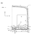
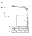
- FIG. 2 is a vertical cross-sectional view of a general portion (AA portion) of the railway vehicle structure shown in FIG. 1 according to the embodiment of the present invention.
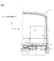
- FIG. 3 is a vertical sectional view of an air conditioner mounting portion (BB portion) of the railroad vehicle structure shown in FIG. 1 according to the embodiment of the present invention.
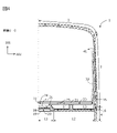
- FIG. 4 is a vertical cross-sectional view of a blowing portion (CC portion) of the railway vehicle structure shown in FIG. 1 according to the embodiment of the present invention.
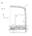
- FIG. 5 is a vertical cross-sectional view of a window portion (DD portion) of the railway vehicle structure shown in FIG. 1 according to the embodiment of the present invention.
- FIG. 1 is a perspective view of a railroad vehicle structure for a high-speed vehicle.
- FIG. 2 is a vertical cross-sectional view of a general portion (AA portion) of the railway vehicle structure shown in FIG. 1 according to the embodiment of the present
- FIG. 6 is a vertical cross-sectional view of a longitudinal end portion (EE portion) of the railway vehicle structure shown in FIG. 1 according to the embodiment of the present invention.
- FIG. 7 is a vertical cross-sectional view of a general portion (AA portion) of the railway vehicle structure shown in FIG. 1 according to another embodiment of the present invention.
- FIG. 8 is a vertical cross-sectional view of a general portion (AA portion) of the railway vehicle structure shown in FIG. 1 in the prior art.
- the rail vehicle is a general term for vehicles operated along the laid track, and means a railroad vehicle, a road train, a new transportation system vehicle, a monorail vehicle, and the like.
- an embodiment of the present invention will be described by exemplifying a railroad vehicle as a typical example of a rail vehicle with reference to the drawings.
- FIG. 1 is a perspective view schematically showing an example of a railroad vehicle structure.
- the vertical (height) direction of the railway vehicle structure 1 is 101
- the width direction and the longitudinal direction orthogonal to the vertical direction are 102 and 103, respectively.
- the railroad vehicle structure 1 includes side structures 3 and 3 (only one of which is shown) erected at both ends of the underframe 4 in the width direction 102, and a wife structure 5 erected at both ends of the underframe 4 in the longitudinal direction 103. 5 (only one is shown) and the roof structure 2 mounted on the upper end of the side structure 3, 3 and the wife structure 5, 5 in the vertical (height) direction 101.
- the side structures 3 and 3 are provided with an entrance / exit for passengers to get on and off, and a window 6 for passengers to see the scenery outside the vehicle.
- Below the underframe 4 an air conditioner 7 that circulates the air inside the vehicle is provided below the underframe 4.
- FIG. 2 shows a cross-sectional view taken along the line AA of the railroad vehicle structure 1 shown in FIG.
- the roof structure 2, the side structure 3, and the underframe 4 are formed by joining two facing face plates and a hollow profile made of an aluminum alloy composed of a plurality of ribs connecting the face plates. Further, the extrusion direction is set to the longitudinal direction 103 of the railway vehicle structure 1.
- the configuration of the underframe 4 will be described in detail.
- the position of the upper side plate 17 of the hollow profile constituting the upper surface of the central underframe 11 located at the center of the width direction 102 in the vertical direction 101 is the upper surface of the end underframe 12 located at the end of the width direction 102. It is higher than the position of the upper side plate 17 of the hollow profile constituting the above in the vertical direction 101. Further, the position of the lower side plate 18 of the hollow profile forming the lower surface of the central underframe 11 in the vertical direction 101 is the vertical direction 101 of the lower side plate 18 of the hollow profile forming the lower surface of the end underframe 12. Higher than the position of.
- the upper side plate 17 and the lower side plate 18 of the central underframe 11 and the end underframe 12 are respectively on a substantially horizontal plane. When the thicknesses of the central underframe 11 and the end underframe 12 are substantially the same, the hollow profile formed in the same process can be used for forming, so that the cost can be reduced.
- the upper side plate 17 includes a first upper side plate 17a located on the upper surface of the central underframe 11, a second upper side plate 17b located on the upper surface of the end underframe 12, and a first upper side plate 17a and a second. It has a third upper side plate 17c that is smoothly connected to the upper side plate 17b.
- the lower side plate 18 includes a first lower side plate 18a located on the lower surface of the central underframe 11, a second lower side plate 18b located on the lower surface of the end underframe 12, and a first lower surface plate 18. It has a third lower side plate 18c in which the side plate 18a and the second lower side plate 18b are smoothly connected.
- the second upper side plate 17b is located below the first upper side plate 17a
- the second lower side plate 18b is located below the first lower side plate 18a.
- the underframe 4 has a mode in which the end underframe 12 is biased downward with respect to the central underframe 11.
- the ends on the center side in the width direction 102 of the lower side plate 18 of the hollow profile forming the end underframe 12 (only one of them is shown) are connected by the closing plate 19, and the lower surface side of the central underframe 11 is shielded. Has been done.
- the upper part of the end frame 12 (second upper side plate 17b, third upper side plate 17c, floor plate 63, floor plate support base 21, and side structure 3 for air supply space and return air surrounded by the inner surface of the vehicle).
- the air supply duct 13 for transporting air from the air conditioner 7 into the vehicle is on the end side in the width direction 102
- the return air duct 14 for transporting air from the vehicle interior to the air conditioner 7 is in the width direction 102. It is provided on the center side.
- the air supply duct 13 and the return air duct 14 extend along the longitudinal direction 103 of the railway vehicle structure 1, and the lower surface of the return air duct 14 is an end frame so that the space can be effectively used.
- the cross section of the return air duct 14 has a pentagonal shape that matches the connecting portion between the end underframe 12 and the central underframe 11.
- the air exhausted from the inside of the vehicle to the outside of the vehicle is carried by the lower side plate 18 (first lower side plate 18a and third lower side plate 18c) of the hollow profile constituting the central underframe 11 and the closing plate 19.
- This is done through the exhaust duct 20 provided in the space surrounded by.
- the exhaust duct 20 extends along the longitudinal direction 103 of the railroad vehicle structure 1, and the upper surface of the exhaust duct 20 is from the central underframe 11 to the central underframe 11 so that the space can be effectively utilized.
- the cross section of the exhaust duct 20 has an isosceles trapezoidal shape that matches the connecting portion between the end underframe 12 and the central underframe 11.
- a floor plate is placed on the upper part of the upper side plate 17 (at least one of the first upper side plate 17a, the second upper side plate 17b, and the third upper side plate 17c) in the vicinity of the joint between the central underframe 11 and the end underframe 12.
- a support base 21 is provided, and a floor plate receiver 16 is provided inside the vehicle of the side structure 3.
- the central floor plate 22 is supported on a substantially horizontal plane by the floor plate support base 21 above the central underframe 11 and the return air duct 14.
- the end floor plate 23 is supported on a substantially horizontal plane by the floor plate support base 21 and the floor plate receiver 16 above the air supply duct 13 and the return air duct 14.
- the central floor plate 22 and the end floor plate 23 form a floor plate.
- a seat support base 32 is provided above the central floor plate 22 and the end floor plate 23, and a seat receiver 15 is provided inside the vehicle of the side structure 3.
- the seat 31 is supported on a substantially horizontal plane by the seat support base 32 and the seat receiver 15.
- An interior panel 33 (indicated by a broken line) is provided on the side surface of the seat 31 to improve the appearance of the inside of the vehicle.
- the gap 25 between the central floor plate 22 and the end floor plate 23 is located below the seat 31.
- FIG. 3 is a vertical cross-sectional view of the air-conditioning mounting portion including the air-conditioning device 7
- FIG. 4 is a vertical cross-sectional view of the blow-in portion between windows
- FIG. 5 is a vertical cross-sectional view of the window portion
- FIG. 6 is a longitudinal end portion. Each shows a vertical cross section.
- the closing plate 19 On the hollow profile constituting the end frame 12, the closing plate 19, the lower surface of the air supply duct 13, the lower surface of the return air duct 14, and the lower surface of the exhaust duct 20. , Each of which is provided with an opening penetrating in the vertical (height) direction 101.
- the air supply 41 carried from the air conditioner 7 into the vehicle is supplied to the inside of the air supply duct 13 through the hollow profile constituting the end underframe 12 and the opening provided on the lower surface of the air supply duct 13. Further, it spreads over the entire longitudinal direction 103 of the railway vehicle structure 1 through the air supply duct 13.
- the return air 42 carried from the inside of the vehicle to the air conditioner 7 is returned to the air conditioner 7 through the hollow profile constituting the end underframe 12 and the opening provided on the lower surface of the return air duct 14.
- the exhaust 43 transported from the inside of the vehicle to the outside of the vehicle is exhausted to the outside of the vehicle by a ventilation device adjacent to the air conditioner 7 through an opening (not shown) provided on the lower surface of the closing plate 19 and the exhaust duct 20.
- the air supply 41 carried through the air supply duct 13 is the air supply duct 13 extending along the vertical (height) direction 101 between the side structure 3 and the interior panel 33 at the blowing portion shown in FIG. It is supplied into the car from the top of the window through the branch.
- the return air 42 from the inside of the vehicle is supplied to the return air duct 14 through the intake portion passing through the gap 25 between the central floor plate 22 and the end floor plate 23 in the window portion shown in FIG.
- the intake portion of the return air 42 from the inside of the vehicle is provided with an opening penetrating in the vertical (height) direction 101 on the upper surfaces of the floor covering 24 and the return air duct 14.
- a portion for taking in the return air 42 from the inside of the vehicle is provided in the window portion (FIG. 5), but as long as it is below the seat 31 so as not to deteriorate the appearance inside the vehicle, it is provided in the blowing portion (FIG. 4). It may be provided.
- the exhaust 43 from the inside of the vehicle is supplied to the exhaust duct 20 through the opening provided in the central floor plate 22 at the end portion in the longitudinal direction shown in FIG.
- an opening penetrating in the vertical (height) direction 101 is also provided on the upper surface of the floor covering 24, the hollow profile constituting the central underframe 11, and the exhaust duct 20.
- the intake portion of the exhaust 43 from the inside of the vehicle is provided at the end portion in the longitudinal direction (FIG. 6) where a toilet or the like where odor is likely to be generated is arranged, but there is air to be exhausted outside the vehicle. It can also be installed in the place of.
- the thickness of the underframe 4 represented by the vertical distance between the upper side plate 17 and the closing plate 19 of the hollow profile is thicker at the central underframe 11, and thus the center. It is possible to secure the rigidity and strength against the airtight pressure that exerts a large bending load on the underframe 11.
- the thickness of the hollow profile constituting the underframe 4 can be reduced, so that the air supply duct 13 and the return air duct 14 are arranged on the upper part of the end underframe 12 to form the central underframe 11.
- the exhaust duct 20 is arranged under the hollow profile, it is possible to avoid interference with the underfloor equipment while maintaining the position of the floor plate 63 in the height direction, and the hollow profile is thickened and compact. Can be avoided. Therefore, it is possible to construct the underframe of the railroad vehicle with a hollow profile while avoiding the increase in the manufacturing cost due to the increase in mass and the welding amount, so that the manufacturing of the railroad vehicle can be simplified and the manufacturing cost can be simplified. Can also be reduced.
- the lower side plate 18 of the hollow profile material constituting the end underframe 12 is arranged on a substantially horizontal plane, it is possible to attach the underfloor equipment by using the receiving metal integrally molded with the hollow profile material. It will be possible. That is, it is not necessary to provide a separate receiver for the mounting portion of the underfloor equipment, which further simplifies the production.
- the upper side plate 17 and the lower side plate 18 of the hollow profile constituting the underframe are smoothly connected from the central portion to the end portion, it is possible to avoid stress concentration due to a sudden change in the thickness of the hollow profile. can.
- FIG. 7 shows a cross-sectional view taken along the line AA of the railroad vehicle structure 1 shown in FIG.
- an air supply space 51 for transporting air from the air conditioner 7 into the vehicle is located on the end side in the width direction 102, and a return air space 52 for transporting air from the vehicle interior to the air conditioner 7. Is on the center side in the width direction 102. In these spaces, the air supply duct and the return air duct shown in the previous embodiment do not exist.
- the air supply space 51 and the return air space 52 extend along the longitudinal direction 103 of the railway vehicle structure 1.
- the exhaust duct 20 may be omitted.
- the central floor plate 22, the end floor plate 23, and the floor plate support base 21 that supports them are made of a heat-insulating material.
- the floorboard is made of wood and the floorboard support is made of rubber.
- the air supply duct and the return air duct can be omitted, so that the mass can be further reduced and the manufacturing cost can be further reduced.
- the upper part of the widthwise end of the underframe is used as an air supply space and a return air space. And can carry the return air.
- the thickness of the underframe in the central part in the width direction where a large bending load acts against the airtight pressure, can be increased without increasing the thickness of the hollow profile, so that the increase in mass and the increase in manufacturing cost can be suppressed. Rigidity and strength against airtight pressure can be ensured. This makes it possible to construct the underframe of the high-speed vehicle with a hollow profile, simplify the production of the rail vehicle, and reduce the production cost.
- the present invention is not limited to the above-described embodiment, and includes various modifications other than the above.
- the above-described embodiment has been described in detail in order to explain the present invention in an easy-to-understand manner, and is not necessarily limited to the one including all the described configurations.
- it is possible to replace a part of the configuration of one embodiment with the configuration of another embodiment and it is also possible to add the configuration of another embodiment to the configuration of one embodiment.
Landscapes
- Engineering & Computer Science (AREA)
- Mechanical Engineering (AREA)
- Life Sciences & Earth Sciences (AREA)
- Wood Science & Technology (AREA)
- Air-Conditioning For Vehicles (AREA)
- Platform Screen Doors And Railroad Systems (AREA)
- Machines For Laying And Maintaining Railways (AREA)
- Chain Conveyers (AREA)
- Electric Propulsion And Braking For Vehicles (AREA)
Priority Applications (4)
| Application Number | Priority Date | Filing Date | Title |
|---|---|---|---|
| JP2021542194A JP7082718B1 (ja) | 2020-09-29 | 2020-09-29 | 軌条車両 |
| US17/762,812 US12330694B2 (en) | 2020-09-29 | 2020-09-29 | Rail vehicle |
| PCT/JP2020/036837 WO2022070240A1 (ja) | 2020-09-29 | 2020-09-29 | 軌条車両 |
| TW110135294A TWI778806B (zh) | 2020-09-29 | 2021-09-23 | 軌道車輛 |
Applications Claiming Priority (1)
| Application Number | Priority Date | Filing Date | Title |
|---|---|---|---|
| PCT/JP2020/036837 WO2022070240A1 (ja) | 2020-09-29 | 2020-09-29 | 軌条車両 |
Publications (1)
| Publication Number | Publication Date |
|---|---|
| WO2022070240A1 true WO2022070240A1 (ja) | 2022-04-07 |
Family
ID=80951486
Family Applications (1)
| Application Number | Title | Priority Date | Filing Date |
|---|---|---|---|
| PCT/JP2020/036837 Ceased WO2022070240A1 (ja) | 2020-09-29 | 2020-09-29 | 軌条車両 |
Country Status (4)
| Country | Link |
|---|---|
| US (1) | US12330694B2 (https=) |
| JP (1) | JP7082718B1 (https=) |
| TW (1) | TWI778806B (https=) |
| WO (1) | WO2022070240A1 (https=) |
Families Citing this family (1)
| Publication number | Priority date | Publication date | Assignee | Title |
|---|---|---|---|---|
| JP2024172700A (ja) * | 2023-06-01 | 2024-12-12 | 株式会社日立製作所 | 軌条車両およびその製造方法 |
Citations (3)
| Publication number | Priority date | Publication date | Assignee | Title |
|---|---|---|---|---|
| JPH07186948A (ja) * | 1993-12-28 | 1995-07-25 | Hitachi Ltd | 車両用空調ダクト構造 |
| US20150203130A1 (en) * | 2012-08-09 | 2015-07-23 | Siemens Aktiengesellschaft | Hollow-chamber profile floor for a rail vehicle |
| WO2015155832A1 (ja) * | 2014-04-08 | 2015-10-15 | 株式会社日立製作所 | 移動車両 |
Family Cites Families (15)
| Publication number | Priority date | Publication date | Assignee | Title |
|---|---|---|---|---|
| US6722287B2 (en) | 2001-02-09 | 2004-04-20 | Trn Business Trust | Roof assembly and airflow management system for a temperature controlled railway car |
| JP3725043B2 (ja) | 2001-04-25 | 2005-12-07 | 株式会社日立製作所 | 軌条車両 |
| JP3725057B2 (ja) | 2001-09-25 | 2005-12-07 | 株式会社日立製作所 | 軌条車両 |
| JP4163925B2 (ja) | 2002-10-09 | 2008-10-08 | 株式会社日立製作所 | 車両構体 |
| JP5227234B2 (ja) | 2009-01-05 | 2013-07-03 | 株式会社日立製作所 | 鉄道車両用の車体構造 |
| DE102012214153A1 (de) * | 2012-08-09 | 2014-03-06 | Siemens Aktiengesellschaft | Einschaliges Bodenprofil für ein Schienenfahrzeug |
| DE102013219794A1 (de) | 2013-09-30 | 2015-04-02 | Siemens Aktiengesellschaft | Schienenfahrzeugwagenkasten |
| FR3024117B1 (fr) * | 2014-07-22 | 2018-03-30 | Alstom Transport Technologies | Parois structurelles pour une caisse de vehicule ferroviaire, procede d'assemblage et vehicule ferroviaire associes |
| JP6356342B2 (ja) * | 2015-05-01 | 2018-07-11 | 株式会社日立製作所 | 軌条車両 |
| CN105083311B (zh) | 2015-06-04 | 2018-08-31 | 山东朗进科技股份有限公司 | 一种空调机组及安装有该空调机组的悬挂式吊轨车辆 |
| JP6552971B2 (ja) * | 2016-01-05 | 2019-07-31 | 株式会社日立製作所 | 軌条車両の台枠構造 |
| JP7103826B2 (ja) * | 2018-04-03 | 2022-07-20 | 日本車輌製造株式会社 | 防振材の構造及び防振床構造を有する鉄道車両 |
| DE102018220741B3 (de) | 2018-11-30 | 2020-04-23 | Siemens Mobility GmbH | Vorrichtung zur Wärmeabfuhr für ein Schienenfahrzeug und Schienenfahrzeug |
| CN113498393B (zh) | 2019-03-13 | 2023-06-16 | 株式会社日立制作所 | 轨条车辆用换气装置 |
| JP7253116B2 (ja) * | 2020-07-09 | 2023-04-05 | 日本車輌製造株式会社 | 鉄道車両の耐火床構造 |
-
2020
- 2020-09-29 JP JP2021542194A patent/JP7082718B1/ja active Active
- 2020-09-29 US US17/762,812 patent/US12330694B2/en active Active
- 2020-09-29 WO PCT/JP2020/036837 patent/WO2022070240A1/ja not_active Ceased
-
2021
- 2021-09-23 TW TW110135294A patent/TWI778806B/zh active
Patent Citations (3)
| Publication number | Priority date | Publication date | Assignee | Title |
|---|---|---|---|---|
| JPH07186948A (ja) * | 1993-12-28 | 1995-07-25 | Hitachi Ltd | 車両用空調ダクト構造 |
| US20150203130A1 (en) * | 2012-08-09 | 2015-07-23 | Siemens Aktiengesellschaft | Hollow-chamber profile floor for a rail vehicle |
| WO2015155832A1 (ja) * | 2014-04-08 | 2015-10-15 | 株式会社日立製作所 | 移動車両 |
Also Published As
| Publication number | Publication date |
|---|---|
| US12330694B2 (en) | 2025-06-17 |
| US20220363295A1 (en) | 2022-11-17 |
| TW202212183A (zh) | 2022-04-01 |
| JP7082718B1 (ja) | 2022-06-08 |
| JPWO2022070240A1 (https=) | 2022-04-07 |
| TWI778806B (zh) | 2022-09-21 |
Similar Documents
| Publication | Publication Date | Title |
|---|---|---|
| EP2476599B1 (en) | Railway car | |
| EP2957476A1 (en) | Vehicle air-conditioning duct, and railway vehicle | |
| EP0672567A1 (en) | Railway vehicle bodies and methods of manufacturing them | |
| JP7082718B1 (ja) | 軌条車両 | |
| TWI912028B (zh) | 軌道車輛 | |
| JP6552971B2 (ja) | 軌条車両の台枠構造 | |
| JP3528079B2 (ja) | 鉄道車両の構体構造 | |
| JP6801145B1 (ja) | 軌条車両 | |
| JP7551569B2 (ja) | 鉄道車両 | |
| JP3532126B2 (ja) | 鉄道車両の空調装置 | |
| JP7104565B2 (ja) | 軌条車両 | |
| JP2009262687A (ja) | 鉄道車両の吹寄構造 | |
| JP7603178B1 (ja) | 鉄道車両及びその製造方法 | |
| JP2025005519A (ja) | 鉄道車両 | |
| JP2639299B2 (ja) | 鉄道車両の車体 | |
| JP6726446B2 (ja) | 鉄道車両 | |
| JP2024166878A (ja) | 軌条車両 | |
| JPH05139298A (ja) | 鉄道車両の車体 | |
| JP6646429B2 (ja) | 移動体の構造 | |
| JP7315423B2 (ja) | 軌条車両 | |
| JP7219657B2 (ja) | 車体間機器の取付構造体の製造方法、車体間機器の取付構造体、及び鉄道車両 | |
| JP7497283B2 (ja) | 軌条車両及びその製造方法 | |
| JPH07304448A (ja) | 鉄道車両の構体 | |
| JPH09169267A (ja) | 車両構体 | |
| JPH0676060B2 (ja) | 鉄道車両の構体構造 |
Legal Events
| Date | Code | Title | Description |
|---|---|---|---|
| ENP | Entry into the national phase |
Ref document number: 2021542194 Country of ref document: JP Kind code of ref document: A |
|
| 121 | Ep: the epo has been informed by wipo that ep was designated in this application |
Ref document number: 20956170 Country of ref document: EP Kind code of ref document: A1 |
|
| NENP | Non-entry into the national phase |
Ref country code: DE |
|
| 122 | Ep: pct application non-entry in european phase |
Ref document number: 20956170 Country of ref document: EP Kind code of ref document: A1 |
|
| WWG | Wipo information: grant in national office |
Ref document number: 202217016740 Country of ref document: IN |
|
| WWG | Wipo information: grant in national office |
Ref document number: 17762812 Country of ref document: US |