WO2022064952A1 - 静電アクチュエータ - Google Patents
静電アクチュエータ Download PDFInfo
- Publication number
- WO2022064952A1 WO2022064952A1 PCT/JP2021/031413 JP2021031413W WO2022064952A1 WO 2022064952 A1 WO2022064952 A1 WO 2022064952A1 JP 2021031413 W JP2021031413 W JP 2021031413W WO 2022064952 A1 WO2022064952 A1 WO 2022064952A1
- Authority
- WO
- WIPO (PCT)
- Prior art keywords
- stator
- counter electrode
- mover
- electrostatic actuator
- electrode
- Prior art date
- Legal status (The legal status is an assumption and is not a legal conclusion. Google has not performed a legal analysis and makes no representation as to the accuracy of the status listed.)
- Ceased
Links
Images




Classifications
-
- H—ELECTRICITY
- H02—GENERATION; CONVERSION OR DISTRIBUTION OF ELECTRIC POWER
- H02N—ELECTRIC MACHINES NOT OTHERWISE PROVIDED FOR
- H02N1/00—Electrostatic generators or motors using a solid moving electrostatic charge carrier
- H02N1/002—Electrostatic motors
- H02N1/004—Electrostatic motors in which a body is moved along a path due to interaction with an electric field travelling along the path
Definitions
- the present invention relates to an electrostatic actuator.
- Patent Document 1 discloses an electrostatic motor as an example of an actuator.
- the electrostatic motor shown in the figure includes a stator and a rotor.
- the stator and rotor each have a plurality of counter electrodes.
- the stator and the rotor are installed separately, and each has a plurality of electrodes.
- One electrode of the stator and one electrode of the rotor form a pair of electrodes, and the electrodes are separated from each other to form a capacitor structure. In this structure, it is difficult to make a pair of electrodes of the same electrode, and it is difficult to utilize repulsive force.
- the present invention was conceived under the above circumstances, and it is an object of the present invention to provide an electrostatic actuator with higher speed and higher output.
- the electrostatic actuator provided by the present invention is an electrostatic actuator including a stator and a mover, which is driven by generating an attractive force and a repulsive force due to an electric field between the stator and the mover.
- One of the stator and the mover comprises a plurality of first capacitor structures each having a first counter electrode and a first non-opposed electrode, and the stator and the other of the mover have a plurality of second. It is provided with a counter electrode and is driven by an attractive force and a repulsive force generated between the first counter electrode and the second counter electrode.
- the other of the stator and the mover comprises a plurality of second capacitor structures each having the second counter electrode and the second non-opposed electrode.
- a rotating shaft for outputting a driving force is provided, and the mover is circular when viewed along the axial direction of the rotating shaft, and is fixed to the rotating shaft.
- the stator has a cylindrical shape with the rotation axis as the central axis, and is provided at a position surrounding the mover.
- the plurality of first capacitor structures and the plurality of second counter electrodes are the first.
- the circular arrangement is centered on the rotation axis so that the 1 facing electrode and the 2nd facing electrode face each other.
- the stator has a shape that extends long in the first direction
- the mover has a smaller dimension in the first direction than the stator and with respect to the stator.
- the plurality of first capacitor structures and the plurality of second counter electrodes are arranged so as to face the second direction perpendicular to the first direction, and the first counter electrode and the second counter electrode are the same. Are arranged along the first direction so that they face each other.
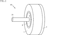
- the electrostatic actuator A1 of the present embodiment includes a stator 1, a mover 2, and a power receiving unit 7.
- the electrostatic actuator A1 is a motor type actuator that is an example of an actuator, and is an actuator that generates a rotational force.
- the stator 1 is a schematic perspective view showing the electrostatic actuator A1.
- FIG. 2 is a cross-sectional view of a cross section perpendicular to the axial direction of the rotating shaft 21, which will be described later. In FIG.
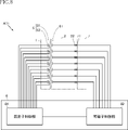
- FIG. 4 is a system configuration diagram of an actuator system using the electrostatic actuator A1.
- the stator 1 is a portion fixed to a peripheral portion where, for example, the electrostatic actuator A1 is installed.
- the stator 1 includes a support 3 and a plurality of capacitor structures 5.
- the support 3 is a member that forms most of the appearance of the stator 1 and supports a plurality of capacitor structures 5.
- the material constituting the support 3 is not limited in any way, and for example, a metal, a resin, or the like is appropriately used.
- the support 3 has a cylindrical shape.
- each capacitor structure 5 has a counter electrode 51, a non-counter electrode 52, and a dielectric layer 53.
- the counter electrode 51 is an electrode arranged inside in the radial direction and faces the mover 2.
- the non-opposed electrode 52 is arranged on the outer side in the radial direction, and is arranged on the side opposite to the mover 2 with the facing electrode 51 interposed therebetween.
- the dielectric layer 53 is sandwiched between the counter electrode 51 and the non-opposite electrode 52, and is a layer made of a dielectric.
- the material of the counter electrode 51 and the non-counter electrode 52 is not limited in any way, and a metal layer or a layer containing carbon is appropriately adopted.
- the material of the dielectric layer 53 is not limited in any way, and is made of a resin, an elastomer, or the like.
- the capacitor structure 5 is not limited as long as it can be in a charged state in which the counter electrode 51 and the non-opposite electrode 52 are intended in the operation of the electrostatic actuator A1 described later.
- FIG. 3 shows an enlarged detailed structure of the stator 1 and the mover 2, and the reference numerals corresponding to the stator 1 and the mover 2 are also shown. Further, in each figure, the stator 1 and the mover 2 have different radial directions in the figure. In the description of the stator 1, the upper side in the figure of FIGS. 3A, 3B and 3C is the inner side in the radial direction, and the left-right direction in the figure is the circumferential direction.
- the insulating layer 31 is provided on the inner peripheral surface of the support 3.
- the insulating layer 31 is for insulating the support 3 and the capacitor structure 5.
- the insulating layer 31 may not be provided.
- the material of the insulating layer 31 is not limited in any way, and is made of, for example, resin.
- the capacitor structure 5 is laminated on the insulating layer 31 in the order of the non-opposed electrode 52, the dielectric layer 53, and the counter electrode 51 from the outside in the radial direction. In the illustrated example, the capacitor structure 5 is covered by a protective layer 32.
- the protective layer 32 is a layer for insulating and protecting the capacitor structure 5 in addition to being charged between the capacitor structure 5 and the capacitor structure 6.
- the material of the protective layer 32 is not limited in any way, and is made of, for example, resin or the like. Further, the protective layer 32 is preferably made of a material having a dielectric constant equal to or higher than that of the dielectric layers 53 and 63, and is made of a material having an insulating property equal to or higher than that of the insulating layers 31 and 41. preferable.
- the recess 3a is provided inside the support 3 in the radial direction.
- the recess 3a is recessed from the inner peripheral surface of the support 3.
- a capacitor structure 5 is housed inside the recess 3a via an insulating layer 31.
- the stacking order of the capacitor structure 5 is the same as in FIG.
- a protective layer 32 is provided so as to cover the inner peripheral surface of the support 3 and the counter electrode 51.
- the support 3 has an electric field shielding portion 35.
- the electric field shielding portion 35 is made of a material capable of shielding an electric field such as metal.
- the electric field shielding portion 35 has a bottom portion 351 and a plurality of wall portions 352.
- the bottom portion 351 is provided at the back of the capacitor structure 5 (lower part in the figure), and extends in the direction in which the plurality of capacitor structures 5 are arranged.
- the plurality of wall portions 352 are provided between the adjacent capacitor structures 5, and the lower end in the figure is connected to the bottom portion 351.
- the capacitor structure 5 is arranged between the two wall portions 352.
- the support 4 has an electric field shielding portion 45 having the same configuration as the electric field shielding portion 35.
- the electric field shielding portion 45 has a bottom portion 451 and a plurality of wall portions 452 having the same configuration as the bottom portion 351 and the plurality of wall portions 352. According to such a configuration, it is possible to suppress leakage of electric field noise that may occur from the capacitor structure 5 and the capacitor structure 6 to the surroundings.
- the electric field shielding unit 35 and the electric field shielding unit 45 may be connected to the ground, or may not be connected to the ground or the power supply.
- the mover 2 is a part that rotates with respect to the stator 1.
- the mover 2 of the present embodiment includes a rotating shaft 21, a support 4, and a plurality of capacitor structures 6.
- the mover 2 is rotatable inward in the radial direction of the stator 1.
- the stator 1 and the mover 2 may be configured to be separated from each other with a gap, for example, or an insulating fluid such as oil may be placed between them. It may be an intervening configuration.
- the support 4 is a member that forms most of the appearance of the mover 2, and supports a plurality of capacitor structures 6.
- the material constituting the support 4 is not limited in any way, and for example, a metal, a resin, or the like is appropriately used.
- the support 3 has a cylindrical shape.
- the rotating shaft 21 is attached to the center of the support 4, and is a shaft that outputs the rotational force of the electrostatic actuator A1.
- the rotating shaft 21 is, for example, a round bar made of metal.
- each capacitor structure 6 has a counter electrode 61, a non-counter electrode 62, and a dielectric layer 63.
- the counter electrode 61 is an electrode arranged on the outer side in the radial direction and faces the counter electrode 51 of the stator 1.
- the non-opposed electrode 62 is arranged on the outer side in the radial direction, and is arranged on the side opposite to the stator 1 with the facing electrode 61 interposed therebetween.
- the dielectric layer 63 is sandwiched between the counter electrode 61 and the non-opposite electrode 62, and is a layer made of a dielectric.
- the material of the counter electrode 61 and the non-counter electrode 62 is not limited in any way, and a metal layer or a layer containing carbon is appropriately adopted.
- the material of the dielectric layer 63 is not limited in any way, and is made of a resin, an elastomer, or the like.
- the capacitor structure 6 is not limited as long as it can be in a charged state in which the counter electrode 61 and the non-opposite electrode 62 are in the intended state in the operation of the electrostatic actuator A1 described later. It is preferable that the thickness of the counter electrode 61 and the non-counter electrode 62 and the thickness of the dielectric layer 63 be thin as long as the normal withstand voltage can be maintained.
- the upper side in the figure of FIGS. 3 (a), (b) and (c) is the radial outside, and the left and right direction in the figure is the circumferential direction.
- the specific example of the mover 2 shown in FIGS. (A), (b) and (c) is the same as the specific example of the stator 1 described above.
- the insulating layer 41 is a layer corresponding to the insulating layer 31, and the protective layer 42 is a layer corresponding to the protective layer 32, and has the same configuration as the protective layer 32.
- the recess 4a is a recess similar to the recess 3a and accommodates the capacitor structure 6.
- the stator 1 has a plurality of capacitor structures 5, and the mover 2 has a plurality of capacitor structures 6. Therefore, one of the capacitor structure 5 and the capacitor structure 6 corresponds to the first capacitor structure of the present invention, and the other corresponds to the second capacitor structure.
- the power receiving unit 7 is for applying a voltage from the outside to the plurality of capacitor structures 6 of the mover 2.
- the power receiving unit 7 has a plurality of sliding terminals 71.
- the plurality of sliding terminals 71 are for maintaining individual continuity while sliding with each other, for example, with the plurality of sliding terminals 22 provided on the mover 2 in a state where the mover 2 is rotated with respect to the stator 1. belongs to.
- the plurality of power receiving units 77 and the plurality of sliding terminals 22 various conventionally known configurations can be appropriately adopted, and an example thereof includes a carbon brush.
- the control unit 8 is used in the actuator system using the electrostatic actuator A1.
- the control unit 8 has, for example, a stator control unit 81 and a mover control unit 82. Further, a rotary encoder (rotary encoder) that detects the rotation angle of the mover 2 for polarity switching control (switchability control) of the plurality of capacitor structures 5 and the plurality of capacitor structures 6 by the stator control unit 81 and the mover control unit 82.
- a detection device such as (not shown) may be appropriately provided.
- the stator control unit 81 and the mover control unit 82 may be configured as separate control modules from each other, or may be configured as separate control modules from each other, or may be configured in one control unit 8 by a circuit portion having a function to be exhibited by each other. May be configured. Regardless of the configuration, it is preferable that the stator control unit 81 and the mover control unit 82 are grounded to a common ground line so that the potential standards of each other are matched.
- the stator control unit 81 is individually connected to each of the counter electrode 51 and the non-opposed electrode 52 of the plurality of capacitor structures 5.
- the stator control unit 81 can appropriately change and set the charging states of the counter electrode 51 and the non-opposite electrode 52 of each capacitor structure 5, for example, a power supply unit, a transformer unit, a switching unit, a control unit (CPU, microcomputer, etc.). ), A memory, etc. are appropriately provided.
- the mover control unit 82 is individually connected to each of the counter electrode 61 and the non-opposite electrode 62 of the plurality of capacitor structures 6 via the power receiving unit 7 (plural sliding terminals 71) and the plurality of sliding terminals 22. There is.
- the mover control unit 82 can appropriately change and set the charging states of the counter electrode 61 and the non-opposite electrode 62 of each capacitor structure 6, for example, a power supply unit, a transformer unit, a switching unit, a control unit (CPU, microcomputer, etc.). ), A memory, etc. are appropriately provided.
- stator control unit 81 and the mover control unit 82 in addition to the configuration in which the individual polarities of the plurality of capacitor structures 5 and the plurality of capacitor structures 6 can be freely set, a plurality of capacitor structures can be freely set. The individual polarities of only one of 5 and the plurality of capacitor structures 6 may be freely set.
- the above-mentioned stator control unit 81 sets the polarities of the plurality of capacitor structures 5 of the stator 1 to be opposite to each other. That is, a certain counter electrode 51 is a positive electrode, and the counter electrode 51 adjacent to the positive electrode is set to a negative electrode.
- the polarities of the plurality of capacitor structures 6 of the mover 2 are set to be opposite to each other by the mover control unit 82. That is, a certain counter electrode 61 is a positive electrode, and the counter electrode 61 adjacent to the positive electrode is set to a negative electrode.
- the counter electrode 61 facing the counter electrode 51 set to the + pole in the radial direction is set to the ⁇ pole
- the counter electrode 61 facing the counter electrode 51 set to the ⁇ pole in the radial direction is set to the + pole. Is set to.
- the movable element 2 is slightly moved counterclockwise in the figure with respect to the stator 1. Then, the repulsive force and the attractive force of the plurality of facing electrodes 51 and the plurality of facing electrodes 61 described above generate a driving force for rotating the mover 2 counterclockwise. As a result, the mover 2 rotates counterclockwise to the state shown in FIG. When this rotation further progresses, the counter electrode 51 and the counter electrode 61, which are adjacent to each other in the circumferential direction in FIG. 5, are closest to each other and face each other.
- the mover 2 can be rotated and the rotational force can be output from the rotating shaft 21.
- the polarity switching control by the stator control unit 81 and the mover control unit 82 may be stopped.
- the plurality of capacitor structures 5 have a structure in which the counter electrode 51 and the non-opposite electrode 52 are arranged so as to separate the dielectric layer 53. Therefore, if the counter electrode 51 and the non-opposite electrode 52 have opposite polarities to each other, the charged states of each other are maintained. Therefore, in the rotation control shown in FIGS. 5 and 6, any counter electrode 51 has an arbitrary polarity. Therefore, it is not necessary to continuously apply the voltage from the stator control unit 81. Further, the charging process in which the counter electrode 51 and the non-opposed electrode 52 forming the capacitor structure 5 have opposite polarities to each other can be performed more smoothly than charging a single counter electrode 51 to either polarity.
- the counter electrode 51 when the counter electrode 61 having the same electrode approaches the counter electrode 51, and if the counter electrode 51 is a simple electrode having no capacitor structure, the counter electrode 51 becomes a counter electrode due to the charging action from the counter electrode 61. Charging that becomes a different electrode of 61 acts.
- the counter electrode 51 is paired with the non-opposite electrode 52 with the dielectric layer 53 interposed therebetween, forming the capacitor structure 5. Therefore, it is possible to effectively suppress the charging action of the counter electrode 61 facing the counter electrode 51. Therefore, according to the electrostatic actuator A1, it is possible to provide an actuator having a higher speed and a higher output.
- the mover 2 has a plurality of capacitor structures 6, and both the stator 1 and the mover 2 are provided with a capacitor structure.
- Embodiment 1st modification> 7 and 8 show a first modification of the electrostatic actuator A1.
- the stator 1 has a plurality of capacitor structures 5
- the mover 2 has a plurality of counter electrodes 61.
- the mover 2 has a plurality of counter electrodes 61 arranged along the circumferential direction, it does not have an electrode having a capacitor structure (non-counter electrode 62 in the above-mentioned example). Therefore, in this variation example, the capacitor structure 5 corresponds to the first capacitor structure of the present invention, the counter electrode 51 corresponds to the first counter electrode of the present invention, and the non-opposite electrode 52 corresponds to the first non-opposite electrode of the present invention. It corresponds to an electrode, and the counter electrode 61 corresponds to the second counter electrode of the present invention.
- stator 1 is provided with a plurality of capacitor structures 5, so that the above-mentioned high speed and high output can be achieved. Further, as can be understood from the present modification, the present invention is not limited to the configuration including both the capacitor structure 5 and the capacitor structure 6.
- the stator 1 has a plurality of counter electrodes 51 arranged along the circumferential direction, it does not have an electrode having a capacitor structure (non-counter electrode 52 in the above-mentioned example). Therefore, in this variation example, the capacitor structure 6 corresponds to the first capacitor structure of the present invention, the counter electrode 61 corresponds to the first counter electrode of the present invention, and the non-opposite electrode 62 corresponds to the first non-opposite electrode of the present invention. It corresponds to the electrode, and the counter electrode 51 corresponds to the second counter electrode of the present invention.
- the stator 1 is provided with a plurality of capacitor structures 5, so that the above-mentioned high speed and high output can be achieved. Further, as can be understood from the present modification, in the present invention, either the stator 1 or the mover 2 may have a capacitor structure.
- FIG. 11 shows a third modification example of the electrostatic actuator A1.
- the electrostatic actuator A13 of this modification has, for example, the cross-sectional structure shown in FIG. 2, the polarities of the plurality of capacitor structures 6 are collectively set. That is, in the mover 2, the opposed electrodes 61 of the plurality of capacitor structures 6 are connected to each other, and the non-opposed electrodes 62 of the plurality of capacitor structures 6 are connected to each other. Therefore, two sliding terminals 22 and two sliding terminals 71 are provided.
- the electrostatic actuator A13 is detected by detecting the relative rotation angles of the stator 1 and the mover 2 and controlling the polarities of the plurality of capacitor structures 5 according to the rotation angles. Can be driven and controlled. Further, by setting the polarities of the plurality of capacitor structures 6 at once, it is possible to reduce the number of the sliding terminals 22 and the sliding terminals 71. Instead of this modification, the configuration may be such that the polarities of the plurality of capacitor structures 5 are set collectively.
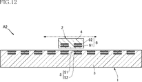
- FIG. 12 shows a second embodiment of the present invention.
- the electrostatic actuator A2 of the present embodiment is configured as a so-called linear actuator.
- the support 3 of the stator 1 has a shape that extends long in the left-right direction in the figure.
- the plurality of capacitor structures 5 are arranged in the left-right direction in the figure along the upper surface of the support 3 in the figure.
- the mover 2 is slidably supported by, for example, a rail member (not shown) and is movable in the left-right direction in the figure with respect to the stator 1.
- the support 4 of the mover 2 has a smaller lateral dimension than the support 3.
- the number of the capacitor structures 6 is smaller than the number of the plurality of capacitor structures 5. In the illustrated example, the number of the capacitor structures 6 is two, but may be one or three or more.
- the electrostatic actuator A2 the polarities of the plurality of capacitor structures 5 and the plurality of capacitor structures 6 are switched and controlled with respect to the stator 1 by, for example, the stator control unit 81 and the mover control unit 82 described above. It is possible to move the child 2 in the left-right direction in the figure. As a result, the electrostatic actuator A2 can output a driving force along the left-right direction in the figure from the mover 2.
- the electrostatic actuator A2 also has a configuration without the non-opposed electrode 62 exemplified in FIGS. 7 and 8, a configuration without the non-opposed electrode 52 exemplified with FIGS. 9 and 10, and further shown in FIG.
- the configuration may be appropriately adopted as a modification of the electrostatic actuator A2.
- the electrostatic actuator according to the present invention is not limited to the above-described embodiment.
- the specific configuration of each part of the electrostatic actuator according to the present invention can be freely redesigned.
Landscapes
- Micromachines (AREA)
Priority Applications (3)
| Application Number | Priority Date | Filing Date | Title |
|---|---|---|---|
| CN202180062986.3A CN116134720A (zh) | 2020-09-28 | 2021-08-26 | 静电致动器 |
| US18/245,160 US20230369992A1 (en) | 2020-09-28 | 2021-08-26 | Electrostatic actuator |
| JP2022551220A JPWO2022064952A1 (https=) | 2020-09-28 | 2021-08-26 |
Applications Claiming Priority (2)
| Application Number | Priority Date | Filing Date | Title |
|---|---|---|---|
| JP2020-161620 | 2020-09-28 | ||
| JP2020161620 | 2020-09-28 |
Publications (1)
| Publication Number | Publication Date |
|---|---|
| WO2022064952A1 true WO2022064952A1 (ja) | 2022-03-31 |
Family
ID=80845158
Family Applications (1)
| Application Number | Title | Priority Date | Filing Date |
|---|---|---|---|
| PCT/JP2021/031413 Ceased WO2022064952A1 (ja) | 2020-09-28 | 2021-08-26 | 静電アクチュエータ |
Country Status (4)
| Country | Link |
|---|---|
| US (1) | US20230369992A1 (https=) |
| JP (1) | JPWO2022064952A1 (https=) |
| CN (1) | CN116134720A (https=) |
| WO (1) | WO2022064952A1 (https=) |
Citations (3)
| Publication number | Priority date | Publication date | Assignee | Title |
|---|---|---|---|---|
| JPH02114871A (ja) * | 1988-10-21 | 1990-04-26 | Olympus Optical Co Ltd | 焦電アクチュエータ |
| JPH10155285A (ja) * | 1996-11-25 | 1998-06-09 | Asmo Co Ltd | 静電アクチュエータ |
| JP2003319666A (ja) * | 2002-04-24 | 2003-11-07 | Japan Science & Technology Corp | 静電浮上モータ |
-
2021
- 2021-08-26 CN CN202180062986.3A patent/CN116134720A/zh not_active Withdrawn
- 2021-08-26 JP JP2022551220A patent/JPWO2022064952A1/ja active Pending
- 2021-08-26 US US18/245,160 patent/US20230369992A1/en not_active Abandoned
- 2021-08-26 WO PCT/JP2021/031413 patent/WO2022064952A1/ja not_active Ceased
Patent Citations (3)
| Publication number | Priority date | Publication date | Assignee | Title |
|---|---|---|---|---|
| JPH02114871A (ja) * | 1988-10-21 | 1990-04-26 | Olympus Optical Co Ltd | 焦電アクチュエータ |
| JPH10155285A (ja) * | 1996-11-25 | 1998-06-09 | Asmo Co Ltd | 静電アクチュエータ |
| JP2003319666A (ja) * | 2002-04-24 | 2003-11-07 | Japan Science & Technology Corp | 静電浮上モータ |
Also Published As
| Publication number | Publication date |
|---|---|
| JPWO2022064952A1 (https=) | 2022-03-31 |
| CN116134720A (zh) | 2023-05-16 |
| US20230369992A1 (en) | 2023-11-16 |
Similar Documents
| Publication | Publication Date | Title |
|---|---|---|
| JP4837449B2 (ja) | 静電モータ | |
| US7671494B2 (en) | Motor/generator | |
| US7750527B2 (en) | Motor/generator | |
| JP2010517498A (ja) | 直線形一次側部品セグメントを備えた回転駆動装置 | |
| JP2011501638A (ja) | 多機能原動機 | |
| US4626722A (en) | Geared motor | |
| WO2022064952A1 (ja) | 静電アクチュエータ | |
| JP2020097973A (ja) | ディスクブレーキ装置 | |
| KR100353457B1 (ko) | 압전형스텝모터 | |
| KR20140091732A (ko) | 기어 전동 장치 및 구동 유닛 | |
| WO2015186442A1 (ja) | 磁石励磁回転電機システム | |
| JP2001145379A (ja) | 光アクチュエータ | |
| JP3872519B2 (ja) | 圧電・ステッピング・モータ | |
| JPWO2015020168A1 (ja) | 動力伝達装置 | |
| EP1835600A2 (en) | Motor/generator | |
| JP2017504297A (ja) | 接触式整流子電動機 | |
| CN212660125U (zh) | 旋转电机 | |
| US20210273539A1 (en) | Multi-rotor electric machine | |
| KR100353451B1 (ko) | 압전형스텝모터 | |
| JP6318097B2 (ja) | 回転電機 | |
| JP2011223745A (ja) | 静電モータ | |
| CN103956880B (zh) | 一种动铁式直线电机多盘式线圈切换装置及方法 | |
| JP2024019974A (ja) | 電動モータ | |
| WO2008001841A1 (en) | Power transmission mechanism, and actuator | |
| JP2007143299A (ja) | 静電モータ |
Legal Events
| Date | Code | Title | Description |
|---|---|---|---|
| 121 | Ep: the epo has been informed by wipo that ep was designated in this application |
Ref document number: 21872084 Country of ref document: EP Kind code of ref document: A1 |
|
| ENP | Entry into the national phase |
Ref document number: 2022551220 Country of ref document: JP Kind code of ref document: A |
|
| NENP | Non-entry into the national phase |
Ref country code: DE |
|
| 122 | Ep: pct application non-entry in european phase |
Ref document number: 21872084 Country of ref document: EP Kind code of ref document: A1 |