WO2022059632A1 - バランサおよびロボットシステム - Google Patents
バランサおよびロボットシステム Download PDFInfo
- Publication number
- WO2022059632A1 WO2022059632A1 PCT/JP2021/033466 JP2021033466W WO2022059632A1 WO 2022059632 A1 WO2022059632 A1 WO 2022059632A1 JP 2021033466 W JP2021033466 W JP 2021033466W WO 2022059632 A1 WO2022059632 A1 WO 2022059632A1
- Authority
- WO
- WIPO (PCT)
- Prior art keywords
- housing
- rod
- axis
- sensor
- balancer
- Prior art date
- Legal status (The legal status is an assumption and is not a legal conclusion. Google has not performed a legal analysis and makes no representation as to the accuracy of the status listed.)
- Ceased
Links
Images



Classifications
-
- B—PERFORMING OPERATIONS; TRANSPORTING
- B25—HAND TOOLS; PORTABLE POWER-DRIVEN TOOLS; MANIPULATORS
- B25J—MANIPULATORS; CHAMBERS PROVIDED WITH MANIPULATION DEVICES
- B25J19/00—Accessories fitted to manipulators, e.g. for monitoring, for viewing; Safety devices combined with or specially adapted for use in connection with manipulators
- B25J19/0008—Balancing devices
- B25J19/0016—Balancing devices using springs
-
- B—PERFORMING OPERATIONS; TRANSPORTING
- B25—HAND TOOLS; PORTABLE POWER-DRIVEN TOOLS; MANIPULATORS
- B25J—MANIPULATORS; CHAMBERS PROVIDED WITH MANIPULATION DEVICES
- B25J13/00—Controls for manipulators
- B25J13/08—Controls for manipulators by means of sensing devices, e.g. viewing or touching devices
- B25J13/086—Proximity sensors
-
- B—PERFORMING OPERATIONS; TRANSPORTING
- B25—HAND TOOLS; PORTABLE POWER-DRIVEN TOOLS; MANIPULATORS
- B25J—MANIPULATORS; CHAMBERS PROVIDED WITH MANIPULATION DEVICES
- B25J19/00—Accessories fitted to manipulators, e.g. for monitoring, for viewing; Safety devices combined with or specially adapted for use in connection with manipulators
- B25J19/06—Safety devices
Definitions
- This disclosure relates to balancers and robot systems.
- a balancer is known that is arranged between a robot's swivel barrel and a first arm that is rotationally driven with respect to the swivel barrel around a horizontal first axis, and for compensating for the gravitational load acting on the first arm. (See, for example, Patent Document 1).
- the current value of the motor that rotationally drives the first arm with respect to the swivel cylinder is monitored to detect a decrease in the generation force of the balancer.
- the balancer is rotatably attached to the first arm and the swivel cylinder around the axis parallel to the first axis by bearings.
- the generated force of the balancer is transmitted to the first arm and the swivel body via the bearing to generate an auxiliary torque for compensating the gravitational load.
- the balancer's mounting parts, swivel cylinder, or first arm may be damaged, so the bearings are damaged or worn early. Need to be detected. However, even if the bearing is damaged or worn, the current value of the motor does not fluctuate significantly, and the abnormality of the bearing cannot be detected by the current value of the motor. Therefore, it is desired to detect bearing damage or wear at an early stage.
- One aspect of the present disclosure is one aspect of the first member of a robot including a first member and a second member rotationally driven around the rotation axis with respect to the first member, to one of the first member and the second member.
- a housing rotatably mounted around the first mounting axis parallel to the rotation axis by bearings, and a second mounting parallel to the rotation axis by a second bearing on the other of the first member or the second member.
- a balancer including a sensor that detects at least one of a positional relationship between the first mounting axis and the housing and a positional relationship between the second mounting axis and the rod in parallel directions.
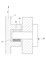
- 2 is a partial vertical sectional view illustrating a moving direction of the housing due to wear of a bearing that rotatably supports the housing of the balancer and the first shaft of FIG. 2.
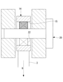
- 2 is a partial vertical sectional view illustrating a moving direction of the rod due to wear of a bearing that rotatably supports the rod of the balancer and the second shaft of FIG. 2. It is a vertical cross-sectional view explaining the difference between the distance detected by the sensor in the balancer of FIG. 2 and the distance at normal time. It is a vertical sectional view which shows the modification of the balancer of FIG.
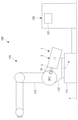
- the robot system 100 includes a robot 110 and a control device 120 for controlling the robot 110.
- the robot 110 is, for example, a vertical 6-axis articulated robot.
- the robot 110 has a base 111 installed on the floor surface F, a swivel body (first member) 112 that can rotate with respect to the base 111 around the first axis A extending in the vertical direction, and a horizontal second axis (rotation).
- a first arm (second member) 113 that can rotate with respect to the swivel cylinder 112 around the axis) B, and a balancer 1 are provided.
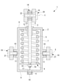
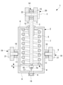
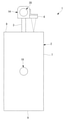
- the balancer 1 includes a housing 2, a rod 3, a movable plate (movable member) 4, a compression coil spring (force generating means) 5, and a sensor 6.
- the housing 2 is arranged on a cylindrical main body portion 7, a flat plate-shaped front end plate (end plate) 8 and a rear end plate (end plate) 9 that close both ends of the main body portion 7 in the axial direction, and a front end plate 8. It includes a bearing 12 that movably supports the rod 3 in the longitudinal direction.
- Each mounting portion 10 is formed in a cylindrical shape extending radially outward from the outer peripheral surface of the main body portion 7 in the same straight line in opposite directions, and has an inner hole 11 having a circular cross section.
- the front end plate 8 is provided with a through hole 13 penetrating in the plate thickness direction in the center, a bearing 12 is arranged in the through hole 13, and the bearing 12 into which the rod 3 is inserted allows the bearing 12 to move in the axial direction of the main body 7. Is supported by.
- a mounting bracket 14 is fixed to one end of a rod 3 arranged outside the housing 2.
- the mounting bracket 14 is provided with a through hole 15 penetrating in a direction orthogonal to the longitudinal axis C of the rod 3.
- a movable plate 4 is fixed to the other end of the rod 3 arranged in the housing 2 by fastening the male screw 3a formed on the rod 3 and the nut 16.
- the movable plate 4 is formed in a disk shape having an outer diameter slightly smaller than the inner diameter of the main body 7.
- the compression coil spring 5 is arranged in a compressed state between the front end plate 8 through which the rod 3 penetrates and the movable plate 4.
- the rod 3 is always subjected to the force generated by the compression coil spring 5 in the direction of being drawn into the housing 2. Further, when the rod 3 is moved in the direction of being pulled out from the housing 2, the amount of compression of the compression coil spring 5 is increased, and the force for pulling the rod 3 into the housing 2 is increased.
- the sensor 6 is, for example, a non-contact distance sensor such as a laser displacement meter, is fixed to the outside of the rear end plate 9 of the housing 2, passes through a through hole 17 provided in the rear end plate 9, and passes through the rod 3. A laser beam is irradiated toward the end, and the reflected light at the end of the rod 3 is detected.
- reference numeral 18 is a bracket for attaching the sensor 6 to the rear end plate 9 of the housing 2.
- Measuring the distance from the tip of the sensor 6 fixed to the housing 2 to the end of the rod 3 means detecting the positional relationship between the rod 3 and the housing 2.
- the balancer 1 configured in this way is between the swivel cylinder 112 and the first arm 113 by a pair of first shafts 19 fixed to the swivel cylinder 112 and a second shaft 20 fixed to the first arm 113. It is attached.
- the first shaft 19 and the second shaft 20 are arranged in parallel with the second axis B, respectively, at intervals from each other.
- the first shaft 19 fixed to the swivel body 112 is inserted into the inner hole 11 of the mounting portion 10 provided in the housing 2 of the balancer 1, and is between the outer surface of the first shaft 19 and the inner surface of the inner hole 11.
- the housing 2 is rotatably supported around the first mounting axis X by an arranged bearing, for example, a slide bearing (first bearing) 21.
- the second shaft 20 fixed to the first arm 113 is inserted into the through hole 15 provided in the mounting bracket 14 of the rod 3, and is arranged between the outer surface of the second shaft 20 and the inner surface of the through hole 15.
- the rod 3 is rotatably supported around the second mounting axis Y by a bearing, for example, a rolling bearing (second bearing) 22.
- the amount of compression of the compression coil spring 5 is larger when the first arm 113 is inclined forward or backward with respect to the vertical direction than when the first arm 113 is arranged in the vertical direction. ..
- the state in which the first arm 113 is inclined forward or backward with respect to the vertical direction includes the first mounting axis X and the second mounting axis Y rather than the state in which the first arm 113 is arranged in the vertical direction.
- the distance between the plane and the second axis B becomes large.
- the auxiliary torque generated by the balancer 1 can be changed in a pattern that is large when the gravitational load torque acting on the first arm 113 is large and small when the gravitational load torque is small, over the entire operating range of the first arm 113. , The load on the motor can be reduced.
- the control device 120 includes at least one processor, at least one memory, and a display (notification unit) 121.
- the first arm 113 is arranged at a predetermined angle with respect to the swivel cylinder 112, for example, 0 °, that is, the first arm 113 is arranged in the vertical direction as shown in FIG.
- the distance detected by the sensor 6 is stored.
- the sliding bearing 21 and the rolling bearing 22 supporting the balancer 1 are at the time of shipment of the robot 110 or immediately after the first and second bearings 21 and 22 supporting the balancer 1 are replaced. It indicates the time when it has not deteriorated.
- the distance to be stored may be the distance actually detected by the sensor 6 or the design value may be stored.
- the processor of the control device 120 manually, periodically, or while the robot 110 is in operation, the distance detected by the sensor 6 with the first arm 113 arranged in the vertical direction. , Calculate the difference from the normal distance stored in the memory. Then, the processor of the control device 120 determines whether or not the calculated absolute value ⁇ of the difference exceeds a predetermined threshold value, and when it is determined that the absolute value ⁇ of the difference exceeds the threshold value, the balancer 1 Notifies the display 121 that an abnormal state has occurred.
- the elastic force of the compression coil spring 5 acts in a direction in which the rod 3 is always drawn into the housing 2. Therefore, the slide bearing 21 provided on the first shaft 19 side is provided with the elastic force of the compression coil spring 5 only on the rear side of the first shaft 19 in order to support the housing 2 pulled forward by the compression coil spring 5.
- the load acts. Further, in order to support the rod 3 pulled backward by the compression coil spring 5 in the rolling bearing 22 provided on the second shaft 20 side, the elastic force of the compression coil spring 5 is applied only to the front side of the second shaft 20. The load acts.
- the distance detected by the sensor 6 is stored in the normal state as shown by the chain line in FIG. 5, regardless of whether the sliding bearing 21 is worn or the rolling bearing 22 is worn. Is smaller than the distance of.
- the display 121 indicates that the display 121 is in an abnormal state. Be notified.
- the bearings 21 and 22 can be replaced before the sliding bearing 21 and the rolling bearing 22 supporting the balancer 1 are further worn and adversely affect other parts. There is an advantage.
- the abnormal state is detected by detecting the positional relationship between the rod 3 and the housing 2 that changes due to the wear. Can be dealt with.
- the abnormal state can be detected earlier by the total value of the wear amounts of both the bearings 21 and 22.
- the balancer 1 that generates a force in the direction of pulling the rod 3 into the housing 2 by the compression coil spring 5 is exemplified.
- a compression coil spring 5 is arranged between the movable plate 4 and the rear end plate 9, and the compression coil spring 5 exerts a force in the direction of pushing out the rod 3 from the inside of the housing 2.
- the balancer 1 to be generated may be adopted.
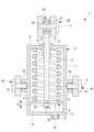
- a through hole 23 may be provided in the front end plate 8 and the distance to the movable plate 4 may be detected by a sensor 6 such as a laser displacement meter fixed to the front end plate 8. Then, the distance or design value detected by the sensor 6 in the normal state is stored, and the absolute value ⁇ of the difference between the distance detected by the sensor and the normal distance as needed or periodically sets the threshold value. It may be determined whether or not it exceeds the limit.
- a laser displacement meter fixed to the rear end plate 9 is adopted as the sensor 6, and the reflected light of the laser light on the end face of the rod 3 is detected.
- the distance to the movable plate 4 (or nut 16) fixed to the rod 3 may be detected.
- the angle of the first arm 113 with respect to the swivel cylinder 112 when detecting the distance can be arbitrarily set.
- the distance obtained by subtracting the threshold value from the normal distance is stored as a new threshold value, and whether or not the detected distance is equal to or less than the new threshold value is stored. May be determined.
- the distance corresponding to the new threshold is usually outside the stroke end and is a distance that cannot be reached in the normal operating state of the robot 110.
- the abnormal state can be detected when the detected distance becomes equal to or less than the threshold value without setting the angle of the first arm 113 with respect to the swivel cylinder 112 when detecting the distance.
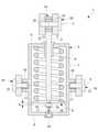
- a contact type switch such as a limit switch (switch) 24 or a non-contact type such as a proximity sensor.
- a switch may be adopted. Even in this case, by arranging the limit switch 24 at a position where the rod 3 operates at a position beyond the stroke end, an abnormal state can be detected when the limit switch 24 operates.
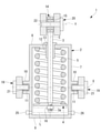
- the light emitter 25 and the light receiver 26 are arranged so as to face the main body 7 of the housing 2, and the light emitter is used.
- An optical sensor in which the optical axis L of the light emitted from the 25 is arranged at a position beyond the stroke end of the rod 3 may be adopted.
- the balancer 1 can be applied not only to a spring balancer having a built-in compression coil spring 5 but also to a case where a gas balancer filled with gas is used.
- the displacement of the housing 2 with respect to the first shaft 19 and the displacement of the rod 3 with respect to the second shaft 20 are totaled. It was determined whether or not it was in an abnormal state.
- the first mounting axis X in the axial direction of the housing 2 (direction orthogonal to both the first mounting axis X and the second mounting axis Y) and the outer surface of the mounting portion 10 ( The distance to the housing 2) may be detected by the sensor 6. Further, as shown in FIG.
- the second mounting axis Y in the axial direction of the rod 3 (direction orthogonal to both the first mounting axis X and the second mounting axis Y) and the end surface (rod 3) of the mounting bracket 14
- the distance may be detected by the sensor 6. Further, the distances of FIGS. 11 and 12 may be detected separately.
- the bearings 21 and 22 are detected separately and abnormal using different threshold values. It may be determined whether or not it is in a state. For example, the amount of wear of the rolling bearing 22 tends to be larger than that of the sliding bearing 21, and in the example of FIG. 1, the amount of wear of the two sliding bearings 21 is sufficiently smaller than that of the single rolling bearing 22. Therefore, it is possible to individually detect the wear of the bearings 21 and 22 and take early countermeasures by detecting the fluctuation of the distance for each of the bearings 21 and 22 and determining whether or not the abnormal state is caused by different threshold values. can.
- the vertical 6-axis articulated robot is exemplified, but the form of the robot 110 may be arbitrary.
- the housing 2 is rotatably supported by the swivel body 112 and the rod 3 is rotatably supported by the first arm 113, the opposite may be true.
- the support position of the housing 2 in the swivel body 112 is set to an intermediate position in the axial direction of the housing 2, it may be applied to the balancer 1 in which the housing 2 is supported behind the rear end plate 9.
Landscapes
- Engineering & Computer Science (AREA)
- Robotics (AREA)
- Mechanical Engineering (AREA)
- Human Computer Interaction (AREA)
- Manipulator (AREA)
Abstract
Description
このバランサを備えるロボットにおいては、旋回胴に対して第1アームを回転駆動するモータの電流値を監視して、バランサの発生力の低下を検出している。
したがって、軸受の損傷あるいは摩耗を早期に検出することが望まれている。
本実施形態に係るロボットシステム100は、図1に示されるように、ロボット110と、ロボット110を制御する制御装置120とを備えている。
ハウジング2は、円筒状の本体部7と、本体部7の軸方向の両端を閉塞する平板状の前端板(端板)8および後端板(端板)9と、前端板8に配置されロッド3を長手方向に移動可能に支持する軸受12とを備えている。
第1アーム113に固定される第2シャフト20は、ロッド3の取付ブラケット14に設けられた貫通孔15内に挿入され、第2シャフト20の外面と貫通孔15の内面との間に配置された軸受、例えば、転がり軸受(第2軸受)22によって、ロッド3を第2取付軸線Y回りに回転可能に支持している。
制御装置120は、正常時において、旋回胴112に対して第1アーム113が所定の角度、例えば、0°、すなわち、図1に示されるように、第1アーム113が鉛直方向に配置されているときに、センサ6により検出された距離を記憶している。
本実施形態に係るバランサ1によれば、圧縮コイルバネ5の弾発力がロッド3をハウジング2内に常に引き込む方向に作用する。したがって、第1シャフト19側に備えられた滑り軸受21には、圧縮コイルバネ5によって前方に引っ張られるハウジング2を支持するために、第1シャフト19の後方側のみに圧縮コイルバネ5の弾発力による荷重が作用する。また、第2シャフト20側に備えられた転がり軸受22には、圧縮コイルバネ5によって後方に引っ張られるロッド3を支持するために、第2シャフト20の前方側のみに圧縮コイルバネ5の弾発力による荷重が作用する。
本実施形態に係るロボットシステム100によれば、センサ6により検出された距離と正常時の距離との差分の絶対値Δが所定の閾値を超える場合には、ディスプレイ121に異常状態である旨が報知される。これにより、バランサ1を支持する滑り軸受21および転がり軸受22の摩耗がそれ以上に進行して、他の部品に悪影響が及ぶ前に、軸受21,22を交換するなどの処置を施すことができるという利点がある。
これに代えて、図11に示されるように、ハウジング2の軸方向(第1取付軸線Xおよび第2取付軸線Yの両方に直交する方向)の第1取付軸線Xと取付部10の外面(ハウジング2)との距離をセンサ6により検出してもよい。また、図12に示されるようにロッド3の軸方向(第1取付軸線Xおよび第2取付軸線Yの両方に直交する方向)の第2取付軸線Yと取付ブラケット14の端面(ロッド3)との距離をセンサ6により検出してもよい。また、図11および図12の距離を別々に検出してもよい。
2 ハウジング
3 ロッド
4 可動板(可動部材)
5 圧縮コイルバネ(力発生手段)
6 距離センサ(センサ)
7 本体部
8 前端板(端板)
9 後端板(端板)
21 滑り軸受(第1軸受)
22 転がり軸受(第2軸受)
24 リミットスイッチ(スイッチ、センサ)
25 発光器(センサ)
26 受光器(センサ)
100 ロボットシステム
110 ロボット
112 旋回胴(第1部材)
113 第1アーム(第2部材)
121 ディスプレイ(報知部)
B 第2軸線(回転軸線)
X 第1取付軸線
Y 第2取付軸線
Claims (6)
- 第1部材と、該第1部材に対して回転軸線回りに回転駆動される第2部材とを備えるロボットの前記第1部材または前記第2部材の一方に、第1軸受によって、前記回転軸線に平行な第1取付軸線回りに回転可能に取り付けられるハウジングと、
前記第1部材または前記第2部材の他方に、第2軸受によって、前記回転軸線に平行な第2取付軸線回りに回転可能に一端が取り付けられるロッドと、
該ロッドを前記ハウジング内に引き込む方向または前記ハウジングから押し出す方向の力を発生させる力発生手段と、
前記第1取付軸線および前記第2取付軸線に直交する方向における前記第1取付軸線と前記ハウジングとの位置関係および前記第2取付軸線と前記ロッドとの位置関係の少なくとも1つを検出するセンサとを備えるバランサ。 - 第1部材と、該第1部材に対して回転軸線回りに回転駆動される第2部材とを備えるロボットの前記第1部材または前記第2部材の一方に、第1軸受によって、前記回転軸線に平行な第1取付軸線回りに回転可能に取り付けられるハウジングと、
前記第1部材または前記第2部材の他方に、第2軸受によって、前記回転軸線に平行な第2取付軸線回りに回転可能に一端が取り付けられるロッドと、
該ロッドを前記ハウジング内に引き込む方向または前記ハウジングから押し出す方向の力を発生させる力発生手段と、
前記第1取付軸線および前記第2取付軸線に直交する方向における前記ハウジングと前記ロッドとの位置関係を検出するセンサとを備えるバランサ。 - 前記ハウジングが、筒状の本体部と、該本体部の軸方向の一端を閉塞する端板とを備え、
前記本体部内に配置される前記ロッドの他端に固定された可動部材を備え、
前記力発生手段が、前記端板と前記可動部材との間に配置された圧縮コイルバネである請求項1または請求項2に記載のバランサ。 - 前記センサが、距離を検出する距離センサである請求項1から請求項3のいずれかに記載のバランサ。
- 前記センサが、前記位置関係が所定の状態となったことを検出するスイッチである請求項1から請求項3のいずれかに記載のバランサ。
- 請求項1から請求項5のいずれかに記載のバランサを備えるロボットと、
前記第1部材と前記第2部材とが特定の相対位置に配置されている状態における、前記センサにより検出された前記位置関係と正常時における前記位置関係との差分が、所定の閾値を超えている場合に、異常状態が発生したことを報知する報知部とを備えるロボットシステム。
Priority Applications (4)
| Application Number | Priority Date | Filing Date | Title |
|---|---|---|---|
| CN202180062669.1A CN116600954B (zh) | 2020-09-17 | 2021-09-13 | 平衡器以及机器人系统 |
| US18/023,258 US12194622B2 (en) | 2020-09-17 | 2021-09-13 | Balancer and robot system |
| JP2022550539A JP7601888B2 (ja) | 2020-09-17 | 2021-09-13 | バランサおよびロボットシステム |
| DE112021003501.0T DE112021003501T5 (de) | 2020-09-17 | 2021-09-13 | Stabilisator und Robotersystem |
Applications Claiming Priority (2)
| Application Number | Priority Date | Filing Date | Title |
|---|---|---|---|
| JP2020-156358 | 2020-09-17 | ||
| JP2020156358 | 2020-09-17 |
Publications (1)
| Publication Number | Publication Date |
|---|---|
| WO2022059632A1 true WO2022059632A1 (ja) | 2022-03-24 |
Family
ID=80777000
Family Applications (1)
| Application Number | Title | Priority Date | Filing Date |
|---|---|---|---|
| PCT/JP2021/033466 Ceased WO2022059632A1 (ja) | 2020-09-17 | 2021-09-13 | バランサおよびロボットシステム |
Country Status (5)
| Country | Link |
|---|---|
| US (1) | US12194622B2 (ja) |
| JP (1) | JP7601888B2 (ja) |
| CN (1) | CN116600954B (ja) |
| DE (1) | DE112021003501T5 (ja) |
| WO (1) | WO2022059632A1 (ja) |
Cited By (1)
| Publication number | Priority date | Publication date | Assignee | Title |
|---|---|---|---|---|
| JP2023180370A (ja) * | 2022-06-09 | 2023-12-21 | 株式会社不二越 | ロボットシステム |
Citations (5)
| Publication number | Priority date | Publication date | Assignee | Title |
|---|---|---|---|---|
| JPS6061188U (ja) * | 1983-10-04 | 1985-04-27 | エスエムシ−株式会社 | 回動腕平衡駆動装置 |
| JPH0531688A (ja) * | 1991-07-22 | 1993-02-09 | Hitachi Ltd | 運搬装置 |
| WO2012086055A1 (ja) * | 2010-12-24 | 2012-06-28 | 株式会社吉田製作所 | マニピュレータおよびレーザ装置 |
| JP2019188513A (ja) * | 2018-04-24 | 2019-10-31 | ファナック株式会社 | ロボット用重力バランサおよびロボット |
| JP2020085831A (ja) * | 2018-11-30 | 2020-06-04 | 川崎重工業株式会社 | ガス圧検知装置、ガス圧検知装置を備えるロボット及びそのガス圧検知方法 |
Family Cites Families (17)
| Publication number | Priority date | Publication date | Assignee | Title |
|---|---|---|---|---|
| HUT67874A (en) * | 1991-08-30 | 1995-05-29 | Morgenegg | Method and device for treatment of interior of non-accessible pipelines |
| JPH05228884A (ja) * | 1992-02-19 | 1993-09-07 | Tokico Ltd | 工業用ロボット |
| JPH06262561A (ja) * | 1993-03-18 | 1994-09-20 | Tokico Ltd | 工業用ロボット |
| JPH0890484A (ja) * | 1994-09-28 | 1996-04-09 | Fanuc Ltd | 永久磁石型バランサを備えた産業用ロボット |
| JPH1015874A (ja) | 1996-07-08 | 1998-01-20 | Yaskawa Electric Corp | 産業用ロボットの重力補償用ばね装置 |
| JP3142791B2 (ja) | 1997-02-12 | 2001-03-07 | 株式会社不二越 | 産業用ロボットのバランサ機構並びに該バランサ機構の取付方法及び調整方法 |
| JP3780520B2 (ja) * | 1997-06-18 | 2006-05-31 | 株式会社安川電機 | 産業用ロボット |
| JP2007007762A (ja) | 2005-06-29 | 2007-01-18 | Honda Motor Co Ltd | 多関節ロボットの関節部監視装置 |
| EP1905551B1 (en) * | 2006-09-27 | 2010-02-24 | Abb Ab | Industrial robot with pressurized air supply in balancing device |
| JP5612150B2 (ja) * | 2013-03-29 | 2014-10-22 | ファナック株式会社 | ガススプリングを備えた多関節ロボット、及びガススプリングの内圧を推定する方法 |
| JP5628953B2 (ja) | 2013-03-29 | 2014-11-19 | ファナック株式会社 | ガススプリングを備えた多関節ロボット、及びガススプリングの内圧を推定する方法 |
| JP6378482B2 (ja) * | 2013-12-25 | 2018-08-22 | 川崎重工業株式会社 | バランサ装置 |
| EP3208571B1 (en) * | 2016-02-18 | 2018-12-05 | Siemens Aktiengesellschaft | Bearing gauge arrangement |
| US10444098B2 (en) * | 2017-04-10 | 2019-10-15 | Fanuc Corporation | Torque sensor and robot |
| WO2019130233A1 (en) * | 2017-12-27 | 2019-07-04 | Gefran S.P.A. | Contactless linear position transducer |
| JP6882238B2 (ja) * | 2018-09-05 | 2021-06-02 | ファナック株式会社 | ロボットのバランサのメインテナンス用治具 |
| DE102022206188A1 (de) * | 2022-06-21 | 2023-12-21 | Aktiebolaget Skf | System zum Bestimmen des Verschleißes eines Lagers und zugehöriges Verfahren |
-
2021
- 2021-09-13 WO PCT/JP2021/033466 patent/WO2022059632A1/ja not_active Ceased
- 2021-09-13 CN CN202180062669.1A patent/CN116600954B/zh active Active
- 2021-09-13 DE DE112021003501.0T patent/DE112021003501T5/de active Pending
- 2021-09-13 JP JP2022550539A patent/JP7601888B2/ja active Active
- 2021-09-13 US US18/023,258 patent/US12194622B2/en active Active
Patent Citations (5)
| Publication number | Priority date | Publication date | Assignee | Title |
|---|---|---|---|---|
| JPS6061188U (ja) * | 1983-10-04 | 1985-04-27 | エスエムシ−株式会社 | 回動腕平衡駆動装置 |
| JPH0531688A (ja) * | 1991-07-22 | 1993-02-09 | Hitachi Ltd | 運搬装置 |
| WO2012086055A1 (ja) * | 2010-12-24 | 2012-06-28 | 株式会社吉田製作所 | マニピュレータおよびレーザ装置 |
| JP2019188513A (ja) * | 2018-04-24 | 2019-10-31 | ファナック株式会社 | ロボット用重力バランサおよびロボット |
| JP2020085831A (ja) * | 2018-11-30 | 2020-06-04 | 川崎重工業株式会社 | ガス圧検知装置、ガス圧検知装置を備えるロボット及びそのガス圧検知方法 |
Cited By (1)
| Publication number | Priority date | Publication date | Assignee | Title |
|---|---|---|---|---|
| JP2023180370A (ja) * | 2022-06-09 | 2023-12-21 | 株式会社不二越 | ロボットシステム |
Also Published As
| Publication number | Publication date |
|---|---|
| CN116600954B (zh) | 2026-03-10 |
| US20230311345A1 (en) | 2023-10-05 |
| US12194622B2 (en) | 2025-01-14 |
| CN116600954A (zh) | 2023-08-15 |
| JPWO2022059632A1 (ja) | 2022-03-24 |
| DE112021003501T5 (de) | 2023-08-10 |
| JP7601888B2 (ja) | 2024-12-17 |
Similar Documents
| Publication | Publication Date | Title |
|---|---|---|
| CN108331998A (zh) | 一种管径调节机构 | |
| US8407896B2 (en) | System and method for setting roller skew | |
| JP5980965B2 (ja) | 複数の回転角検出器により回転角を更新するロボット制御装置 | |
| KR101685422B1 (ko) | 촬상 장치 지지용 조립체 | |
| WO2014112129A1 (ja) | 油圧ショベルおよび油圧ショベルの油圧シリンダのストローク計測方法 | |
| JP2016161465A (ja) | 車両の耐久試験装置 | |
| WO2022059632A1 (ja) | バランサおよびロボットシステム | |
| US20180029197A1 (en) | Clamp device | |
| JP2003529754A (ja) | 距離測定装置 | |
| JP6875405B2 (ja) | 斜板角センサ | |
| JP6549812B2 (ja) | トルクセンサおよびロボット | |
| JP2019074416A (ja) | 軸受状態検出装置 | |
| JP2019113459A (ja) | 歪みセンサ、多軸力センサおよびロボット | |
| JP2020104249A (ja) | 産業用ロボットシステム | |
| JP2017217753A (ja) | 固定振れ止め | |
| US11378380B2 (en) | Rotational angle sensor holding system | |
| JP7569001B2 (ja) | 駆動装置、エンコーダユニット、及びロボット装置 | |
| US9399259B2 (en) | Boring device | |
| CN110207626A (zh) | 一种平面度的激光测量装置及方法 | |
| JP5368537B2 (ja) | 工具フローティング機構 | |
| JP5312917B2 (ja) | 揺動回転試験装置 | |
| KR102487043B1 (ko) | 엑츄에이팅 기능을 갖는 스프링 행거 | |
| JP2009109339A (ja) | 振動測定装置および振動測定方法 | |
| JP2020159864A (ja) | 回転載物台 | |
| JPH11141537A (ja) | 弾性ヒンジ機構およびその弾性ヒンジ機構を用いた計測装置 |
Legal Events
| Date | Code | Title | Description |
|---|---|---|---|
| 121 | Ep: the epo has been informed by wipo that ep was designated in this application |
Ref document number: 21869319 Country of ref document: EP Kind code of ref document: A1 |
|
| ENP | Entry into the national phase |
Ref document number: 2022550539 Country of ref document: JP Kind code of ref document: A |
|
| WWE | Wipo information: entry into national phase |
Ref document number: 202180062669.1 Country of ref document: CN |
|
| 122 | Ep: pct application non-entry in european phase |
Ref document number: 21869319 Country of ref document: EP Kind code of ref document: A1 |