WO2022059614A1 - 関節機構及びロボットアーム機構 - Google Patents
関節機構及びロボットアーム機構 Download PDFInfo
- Publication number
- WO2022059614A1 WO2022059614A1 PCT/JP2021/033300 JP2021033300W WO2022059614A1 WO 2022059614 A1 WO2022059614 A1 WO 2022059614A1 JP 2021033300 W JP2021033300 W JP 2021033300W WO 2022059614 A1 WO2022059614 A1 WO 2022059614A1
- Authority
- WO
- WIPO (PCT)
- Prior art keywords
- arm
- transmission member
- piston rod
- joint mechanism
- balancer
- Prior art date
Links
- 230000007246 mechanism Effects 0.000 title claims abstract description 85
- 230000005540 biological transmission Effects 0.000 claims abstract description 64
- 230000006835 compression Effects 0.000 description 12
- 238000007906 compression Methods 0.000 description 12
- 230000004048 modification Effects 0.000 description 12
- 238000012986 modification Methods 0.000 description 12
- 239000003638 chemical reducing agent Substances 0.000 description 9
- 230000000694 effects Effects 0.000 description 3
- 238000000034 method Methods 0.000 description 3
- 230000005484 gravity Effects 0.000 description 2
- 230000009467 reduction Effects 0.000 description 2
- 230000008859 change Effects 0.000 description 1
- 230000002708 enhancing effect Effects 0.000 description 1
- 238000009434 installation Methods 0.000 description 1
- 210000001577 neostriatum Anatomy 0.000 description 1
- 230000003068 static effect Effects 0.000 description 1
Images


Classifications
-
- B—PERFORMING OPERATIONS; TRANSPORTING
- B25—HAND TOOLS; PORTABLE POWER-DRIVEN TOOLS; MANIPULATORS
- B25J—MANIPULATORS; CHAMBERS PROVIDED WITH MANIPULATION DEVICES
- B25J9/00—Programme-controlled manipulators
- B25J9/10—Programme-controlled manipulators characterised by positioning means for manipulator elements
-
- B—PERFORMING OPERATIONS; TRANSPORTING
- B25—HAND TOOLS; PORTABLE POWER-DRIVEN TOOLS; MANIPULATORS
- B25J—MANIPULATORS; CHAMBERS PROVIDED WITH MANIPULATION DEVICES
- B25J19/00—Accessories fitted to manipulators, e.g. for monitoring, for viewing; Safety devices combined with or specially adapted for use in connection with manipulators
- B25J19/0008—Balancing devices
- B25J19/0012—Balancing devices using fluidic devices
Definitions
- the present invention relates to a joint mechanism and a robot arm mechanism.
- the balancer mechanism is composed of a casing that is tiltably connected to the base and a piston rod that is slidably provided inside the casing.
- the tip of the piston rod is rotatably connected to the arm and is pulled toward the inside of the casing.
- the piston rod is pulled out of the casing as the arm rotates, the arm is pulled by the piston rod in the direction opposite to the direction of the load due to gravity, thereby assisting the power of the mechanism that drives the arm. can.
- the support member of the arm must receive two types of loads, a load due to the weight of the arm and a load due to the traction force generated by the balancer device. Therefore, it is desired to reduce the load acting on the support member of the arm in the industrial robot provided with the balancer mechanism.
- the joint mechanism is a base, an arm, a support member that rotatably supports the arm with respect to the base, and a load torque applied around the rotation center line of the arm due to the weight of the arm. It is equipped with a balancer mechanism that generates auxiliary torque.
- the balancer mechanism converts the casing rotatably supported by the base, the piston rod inserted into the casing, the balancer body having the traction means for pulling the piston rod, and the traction force generated by the traction means into auxiliary torque.
- It has a transmission member that transmits to the arm.
- the transmission member is rotatably supported on the base via a shaft as a separate body from the support member.
- the transmission member is engaged with the tip of the piston rod at a first position separated by a first distance from the centerline of the shaft and engaged with an arm at a second position separated by a second distance from the centerline of the shaft.
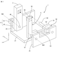
- FIG. 1 is a perspective view of a joint mechanism according to an embodiment.
- FIG. 2 is an exploded perspective view of the joint mechanism of FIG.
- FIG. 3 is a plan view of the joint mechanism of FIG.
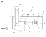
- FIG. 4 is a side view showing a reference posture of the arm of the joint mechanism of FIG.
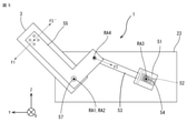
- FIG. 5 is a side view showing the tilting posture of the arm of the joint mechanism of FIG. 1.
- FIG. 6 is a side view showing a reference posture of the arm of the joint mechanism according to the first modification of the embodiment.
- FIG. 7 is a side view showing a reference posture of the arm of the joint mechanism according to the second modification of the embodiment.
- the joint mechanism according to the present embodiment can be used alone or as a joint mechanism such as a robot arm mechanism.
- the joint mechanism 1 includes a base 2, a rod-shaped arm 3 rotatably supported with respect to the base 2, an arm drive mechanism 4 for driving the arm 3, and an arm 3. It has a balancer mechanism 5 that functions as a balancer that reduces the load on the bearings and the like that support the bearing.
- the base 2 has a rectangular bottom plate 21 and a pair of side plates 23, 25 provided so as to be parallel to both edges of the bottom plate 21.
- the axis parallel to the thickness direction of the bottom plate 21 is the Z axis
- the axis parallel to the thickness direction of the side plates 23, 25 is the X axis
- the X axis and Z is used as the Y axis as appropriate.
- the arm drive mechanism 4 is supported by one of the pair of side plates 23 and 25.
- the arm drive mechanism 4 includes a motor 41 that generates power to rotate the arm 3 and a speed reducer 43 that reduces the rotation of the motor 41.
- the arm drive mechanism 4 is configured such that the center line RA1 (rotating shaft RA1) of the output shaft 45 of the speed reducer 43 is parallel to the X axis.
- the arm 3 is attached to the case of the speed reducer 43 via a bearing 47, and is fastened to the output shaft 45 of the speed reducer 43 by a fixing tool such as a bolt. As a result, the arm 3 can be rotated around the rotation shaft RA1 parallel to the X axis with the rotation of the output shaft 45 of the speed reducer 43.
- the balancer mechanism 5 has a balancer main body 50 and a transmission member 55.
- the balancer main body 50 has a casing 51, a piston rod 53 inserted into the casing 51, and a towing means 52 for pulling the piston rod 53 into the inside of the casing 51.
- the compression coil spring 52 is housed inside the casing 51 in a compressed state.
- One end of the piston rod 53 is connected to the compression coil spring 52.
- the casing 51 is rotatably provided around the X axis with respect to the base 2.
- the shaft 54 is fixed between the pair of side plates 23 and 25 so that the center line RA3 (rotating shaft RA3) is parallel to the X axis.
- a casing 51 is attached to the shaft 54 via a bearing or the like. Thereby, the casing 51 can be rotated around the rotation axis RA3 parallel to the X axis.
- the transmission member 55 is composed of a plate having an L shape. One end of the transmission member 55 is rotatably connected to the other end of the piston rod 53 around an axis RA4 parallel to the X axis. The other end of the transmission member 55 is fixed to the position on the tip end side of the arm 3 via the fixing member 56. The transmission member 55 is rotatably provided around the X axis with respect to the base 2. Typically, the shaft 57 is fixed to the other side plate 25 of the pair of side plates 23, 25 so that the center line RA2 coincides with the rotation axis RA1 of the arm 3. A transmission member 55 is attached to the shaft 57 via a bearing or the like.
- the transmission member 55 can be rotated around the center line RA2 (rotation axis RA2) that coincides with the rotation axis of the arm 3.
- the shaft 57 that supports the transmission member 55 is separate from the shaft 57 and the bearing 47 that support the arm 3, and is separated from the shaft 57 and the bearing 47.
- the arm 3 and the transmission member 55 are fixed at the ends of each other, but the support structure of the transmission member 55 with respect to the base 2 is separate from the support structure of the arm 3 with respect to the base 2.
- the composition is one feature.
- the rotation angle of the arm 3 when the center line of the arm 3 is parallel to the Z axis (vertical axis) is 0 degree.
- This posture is used as the reference posture of the arm 3.
- the load torque F1 around the rotation shaft RA1 due to the weight of the arm 3 is not generated on the bearing 47 that supports the arm 3.
- FIG. 5 when the arm 3 is tilted (rotated) from the reference posture, a load torque F1 around the rotation shaft RA1 is generated in the bearing 47 supporting the arm 3 due to the weight of the arm 3. .
- the balancer mechanism 5 functions as follows.
- the transmission member 55 is rotated around the rotation shaft RA2.
- the distance of the rotation shaft RA4 at the connection point between the transmission member 55 and the piston rod 53 and the angle around the X axis change with respect to the rotation shaft RA3 of the casing 51.
- the casing 51 is rotated around the rotation shaft RA3 so that the piston rod 53 is arranged along a straight line passing through the rotation shaft RA3 and the rotation shaft RA4.
- the piston rod 53 is pulled out of the casing 51 against the traction force of the compression coil spring 52.
- the length of the piston rod 53 pulled out from the casing 51 is from the rotation shaft RA3 to the rotation shaft RA4 in the tilting posture of the arm 3 with respect to the distance from the rotation shaft RA3 to the rotation shaft RA4 in the reference posture of the arm 3. Corresponds to the difference in distance.
- the piston rod 53 pulled out from the casing 51 is pulled inside the casing 51 by the compression coil spring 52.
- the traction force F2 generated by the compression coil spring 52 is converted into an auxiliary torque F2'around the rotation shaft RA2 (rotation shaft RA1) by the transmission member 55 and transmitted to the arm 3.
- the balancer mechanism 5 is not directly connected to the arm 3, but is connected to the tip end side of the arm 3 via the transmission member 55, thereby achieving the following effects. That is, in the configuration in which the piston rod 53 of the balancer mechanism 5 is directly connected to the arm 3, the traction force generated by the compression coil spring 52 also acts as a load on the bearing 47 supporting the arm 3. Therefore, the bearing 47 that supports the arm 3 must receive two loads, a load due to the traction force generated by the compression coil spring 52 and a load due to the weight of the arm 3. According to the joint mechanism 1 according to the present embodiment, the traction force generated by the compression coil spring 52 is transmitted to the tip end side of the arm 3 via the transmission member 55.
- the shaft 57 that supports the transmission member 55 is separate from the bearing 47 that supports the arm 3.
- the traction force generated by the compression coil spring 52 acts directly on the shaft 57 that supports the transmission member 55 as a load, but does not act directly on the bearing 47 that supports the arm 3 as a load.
- the balancer mechanism 5 only applies a moment due to the combined torque (F1-F2') described above to the bearing 47 that supports the arm 3.
- the load on the bearing 47 that supports the arm 3 can be reduced.
- the risk of failure of the bearing 47 that supports the arm 3 and the speed reducer 43 (motor 41) that drives the arm 3 can be reduced, and a longer life can be realized.
- the load applied to the bearing 47 supporting the arm 3 is small, the size of the bearing 47 can be reduced. This contributes to the reduction of component costs.
- the static torque generated in the motor 41 can be reduced. This contributes to the reduction of the power consumption of the joint mechanism 1 and the robot including the joint mechanism 1.
- the transmission member 55 is visually separated from the arm 3.
- the rotation shaft RA2 of the transmission member 55 coincides with the rotation shaft RA1 of the arm 3
- the transmission member 55 can be easily accommodated inside the arm 3.
- the joint mechanism 1 can be miniaturized, but also the effect of simplifying the appearance and enhancing the aesthetics and the cable wired to the outside of the joint mechanism 1 can be obtained. This has the effect of avoiding a situation in which the striatum is complicatedly inserted between the arm 3 and the transmission member 55 and the wire is broken.
- the joint mechanism 1 has a coil spring type balancer main body 50 that employs a compression coil spring 52 as the traction means 52.
- the configuration of the balancer main body 50 is not limited to this as long as it can generate a traction force that pulls the piston rod 53 back into the casing 51.
- the balancer main body 50 has a gas spring system in which when the piston rod 53 is pulled out from the casing 51, the compressible gas enclosed in the casing 51 is compressed and the piston rod 53 is pulled back into the casing 51 by the repulsive force.
- Known methods such as a method using an air cylinder and a method using hydraulic pressure can be adopted.
- the shape of the transmission member 55 is not limited to this embodiment. If the transmission member 55 can be fixed at the position on the tip end side of the arm 3, can be rotatably supported coaxially with the rotation shaft RA1 of the arm 3, and can be rotatably connected to the piston rod 53,
- it may be a plate having a dogleg shape or an arch shape.
- the transmission member 55 is typically configured so that the second distance L2 is longer than the first distance L1. However, it does not deny that the second distance L2 is equal to or less than the first distance L1, and the transmission member 55 is used in terms of the magnitude of the traction force, the magnitude of the required auxiliary torque, the installation space of the balancer mechanism 5, and the like. These parameters L1 and L2 can be determined.
- the support structure of the arm 3 with respect to the base 2 is not limited to this embodiment.
- the arm 3 may be configured to be connected to the base 2 via a bearing 47, or the arm 3 may be configured to be directly connected to the output shaft 45 of the speed reducer 43.
- the balancer mechanism 5 functions to reduce the load applied to the output shaft 45 of the speed reducer 43 that supports the arm 3.
- the support structure of the transmission member 55 with respect to the base 2 is not limited to this embodiment.
- the support structure of the transmission member 55 may be different from the support structure of the arm 3.
- the shaft 57 to which the transmission member 55 is fixed may be rotatably attached to the base 2.
- the transmission member 55 may be rotatably supported around the X axis by another member whose position is fixed with respect to the base 2. Similar to the support structure of the transmission member 55 for the base 2, the support structure of the casing 51 for the base 2 is not limited to this embodiment.
- one end of the transmission member 55 is rotatably connected to the piston rod 53 of the balancer mechanism 5, and the other end is fixed to the position on the tip end side of the arm 3.
- the balancer mechanism 5 can function by tilting the arm 3 from the reference posture even at a small angle.
- the balancer mechanism 5 may be configured to function when the arm 3 rotates from the reference posture to a predetermined angle or more.
- the first modification shows a configuration in which the engagement structure between the other end of the transmission member 55 and the arm 3 is changed
- the second modification shows a configuration in which the engagement structure between the piston rod 53 and one end of the transmission member 55 is changed. The configuration is shown.
- the other end of the transmission member 55 is a free end.
- the arm 3 is provided with protrusions 31 and 33 that engage with the transmission member 55 when the arm 3 is tilted from a reference posture to a predetermined angle. Since the other end of the transmission member 55 is not fixed at the position on the tip end side of the arm 3, the rotation shaft RA2 of the transmission member 55 does not need to match the rotation shaft RA1 of the arm 3.
- the arm 3 is tilted by a predetermined angle or more from the reference posture in a state where the end portion of the transmission member 55 is in contact with the protrusions 31 and 33 provided on the arm 3.
- the balancer mechanism 5 can be made to function.
- the balancer mechanism 5 does not function until the end of the transmission member 55 comes into contact with the protrusions 31 and 33 provided on the arm 3 and the arm 3 is tilted from the reference posture to a predetermined angle. Since the range of the rotation angle in which the balancer mechanism 5 functions can be narrowed, the stroke length required for the piston rod 53 can be shortened, and the balancer mechanism 5 can be miniaturized.
- the balancer mechanism 5 does not function until the arm 3 is tilted from the reference posture to a predetermined angle, in which the piston rod 53 is slid along the slit 59 of the transmission member 55. Since the range of the rotation angle in which the balancer mechanism 5 functions can be narrowed, the stroke length required for the piston rod 53 can be shortened, and the balancer mechanism 5 can be miniaturized.
Landscapes
- Engineering & Computer Science (AREA)
- Robotics (AREA)
- Mechanical Engineering (AREA)
- Manipulator (AREA)
Abstract
目的は、バランサ機構を備えた産業用ロボットにおいてアームの支持部材に作用する負荷を軽減することにある。関節機構1は、アーム3の重量により支持部材45にかかるアームの回動中心線周りの負荷トルクに対抗する補助トルクを発生するバランサ機構5を備える。バランサ機構は、ベースに回動自在に支持されるケーシング51、ケーシングに挿入されるピストンロッド53、及びピストンロッドを牽引する牽引手段52を有するバランサ本体50と、牽引手段により発生された牽引力を補助トルクに変換してアームに伝達する伝達部材55とを有する。伝達部材は、支持部材とは別体としてベースに回動自在に軸支され、その一端側がピストンロッドの先端に係合され、他端側がアームに係合される。
Description
本発明は、関節機構及びロボットアーム機構に関する。
多関節型の産業用ロボットでは、重力による負荷の方向とは反対方向に力を発生させてアームを駆動する機構の動力を補助するバランサ機構を備えた産業用ロボットが知られている(例えば、特許文献1)。例えば、バランサ機構は、ベースに傾動可能に連結されたケーシングとケーシングの内部を摺動自在に設けられるピストンロッドとから構成される。ピストンロッドは、その先端がアームに回転可能に接続され、ケーシングの内部に向かって牽引されている。アームの回転に伴って、ピストンロッドがケーシングから引き出されることにより、アームは、ピストンロッドにより重力による負荷の方向とは逆向きに引っ張られ、それによりアームを駆動する機構の動力を補助することができる。
従来の構造において、アームの支持部材は、アームの重量による負荷とバランサ装置により発生された牽引力による負荷との2種類の負荷を受けなくてはならない。そのため、バランサ機構を備えた産業用ロボットにおいてアームの支持部材に作用する負荷を軽減することが望まれている。
本開示の一態様に係る関節機構は、ベースと、アームと、アームをベースに対して回動自在に支持する支持部材と、アームの重量によりアームの回動中心線周りにかかる負荷トルクに対抗する補助トルクを発生するバランサ機構とを具備する。バランサ機構は、ベースに回動自在に支持されるケーシング、ケーシングに挿入されるピストンロッド、及びピストンロッドを牽引する牽引手段を有するバランサ本体と、牽引手段により発生された牽引力を補助トルクに変換してアームに伝達する伝達部材とを有する。伝達部材は、支持部材とは別体としてベースにシャフトを介して回動自在に軸支される。伝達部材は、シャフトの中心線から第1距離を隔てた第1の位置においてピストンロッドの先端に係合され、シャフトの中心線から第2距離を隔てた第2の位置においてアームに係合される。
一態様によれば、バランサ機構を備えた産業用ロボットにおいてアーム支持部材に作用する負荷を軽減することができる。
以下、図面を参照しながら本実施形態に係る関節機構を説明する。以下の説明において、略同一の機能及び構成を有する構成要素については、同一符号を付し、重複説明は必要な場合にのみ行う。
本実施形態に係る関節機構は、それ単独で使用することができるし、ロボットアーム機構などの関節機構としても使用することができる。
図1~図4に示すように、関節機構1は、ベース2と、ベース2に対して回動自在に支持される棒状のアーム3と、アーム3を駆動するアーム駆動機構4と、アーム3を支持するベアリング等への負荷を軽減するバランサとして機能するバランサ機構5と、を有する。
ベース2は、矩形状の底板21と、底板21の両縁に互いに平行になるように設けられた一対の側板23,25と、を有する。以下の説明において、底板21の厚み方向に平行な軸をZ軸、側板23,25の厚み方向(一対の側板23,25が離された方向)に平行な軸をX軸、X軸とZ軸とに直交する軸をY軸として、適宜使用する。
アーム駆動機構4は、一対の側板23,25のうち一方の側板23に支持される。アーム駆動機構4は、アーム3を回動させる動力を発生するモータ41と、モータ41の回転を減速する減速機43とを有する。アーム駆動機構4は、減速機43の出力シャフト45の中心線RA1(回動軸RA1)がX軸と平行になるように構成される。アーム3は、減速機43のケースにベアリング47を介して取り付けられ、ボルト等の固定具により減速機43の出力シャフト45に締結される。それにより、減速機43の出力シャフト45の回動に伴って、アーム3をX軸と平行な回動軸RA1周りに回動させることができる。
バランサ機構5は、バランサ本体50と伝達部材55とを有する。
バランサ本体50は、ケーシング51と、ケーシング51に挿入されたピストンロッド53と、ピストンロッド53をケーシング51の内部に牽引する牽引手段52と、を有する。典型的には、牽引手段52として、ケーシング51の内部には圧縮コイルバネ52が圧縮された状態で収容されている。この圧縮コイルバネ52にピストンロッド53の一端が接続されている。それにより、ケーシング51の内部から引き出されたピストンロッド53を圧縮コイルバネ52によりケーシング51の内部に向かって牽引することができる。ケーシング51は、ベース2に対してX軸周りに回動自在に設けられる。典型的には、一対の側板23,25の間に、中心線RA3(回動軸RA3)がX軸と平行になるように、シャフト54が固定される。このシャフト54にはベアリング等を介してケーシング51が取り付けられる。それにより、ケーシング51をX軸と平行な回動軸RA3周りに回動させることができる。
バランサ本体50は、ケーシング51と、ケーシング51に挿入されたピストンロッド53と、ピストンロッド53をケーシング51の内部に牽引する牽引手段52と、を有する。典型的には、牽引手段52として、ケーシング51の内部には圧縮コイルバネ52が圧縮された状態で収容されている。この圧縮コイルバネ52にピストンロッド53の一端が接続されている。それにより、ケーシング51の内部から引き出されたピストンロッド53を圧縮コイルバネ52によりケーシング51の内部に向かって牽引することができる。ケーシング51は、ベース2に対してX軸周りに回動自在に設けられる。典型的には、一対の側板23,25の間に、中心線RA3(回動軸RA3)がX軸と平行になるように、シャフト54が固定される。このシャフト54にはベアリング等を介してケーシング51が取り付けられる。それにより、ケーシング51をX軸と平行な回動軸RA3周りに回動させることができる。
伝達部材55はL字形状を有する板に構成される。伝達部材55の一端はピストンロッド53の他端にX軸と平行な軸RA4周りに回動自在に接続される。伝達部材55の他端はアーム3の先端側の位置に固定部材56を介して固定される。伝達部材55は、ベース2に対してX軸周りに回動自在に設けられる。典型的には、一対の側板23,25のうち他方の側板25に中心線RA2がアーム3の回動軸RA1と一致するようにシャフト57が固定される。このシャフト57にはベアリング等を介して伝達部材55が取り付けられる。それにより、伝達部材55をアーム3の回動軸と一致する中心線RA2(回動軸RA2)周りに回動させることができる。伝達部材55を支持するシャフト57は、アーム3を支持するシャフト57及びベアリング47とは別体であり、シャフト57及びベアリング47に対して分離されている。このように、アーム3と伝達部材55とは互いの端部箇所において固定されているが、ベース2に対する伝達部材55の支持構造がベース2に対するアーム3の支持構造とは別体になるように構成したことは1つの特徴である。
図4に示すように、アーム3の中心線がZ軸(鉛直軸)と平行なときのアーム3の回動角度を0度とする。この姿勢をアーム3の基準姿勢とする。アーム3が基準姿勢であるとき、アーム3を支持するベアリング47には、アーム3の重量による回動軸RA1周りの負荷トルクF1は発生しない。一方、図5に示すように、アーム3が基準姿勢から傾動(回動)したとき、アーム3を支持するベアリング47には、アーム3の重量による回動軸RA1周りの負荷トルクF1が発生する。このとき、バランサ機構5は以下のように機能する。すなわち、アーム3の回動に追従して、伝達部材55は回動軸RA2周りに回動される。伝達部材55の回動に伴って、ケーシング51の回動軸RA3に対する、伝達部材55とピストンロッド53との接続箇所の回動軸RA4の距離、X軸周りの角度が変化する。ケーシング51は、回動軸RA3と回動軸RA4とを通る直線に沿ってピストンロッド53が配置されるように、回動軸RA3周りに回動される。ピストンロッド53は圧縮コイルバネ52による牽引力に抗ってケーシング51から引き出される。ケーシング51から引き出されるピストンロッド53の長さは、アーム3の基準姿勢時における回動軸RA3から回動軸RA4までの距離に対するアーム3の傾動姿勢時における回動軸RA3から回動軸RA4までの距離の差に対応する。ケーシング51から引き出されたピストンロッド53は圧縮コイルバネ52によりケーシング51の内部に牽引される。圧縮コイルバネ52により発生された牽引力F2は伝達部材55により回動軸RA2(回動軸RA1)周りの補助トルクF2´に変換され、アーム3に伝達される。補助トルクF2´は、アーム3の重量による回動軸RA1周りの負荷トルクF1に対して逆向きに作用する。したがって、アーム3を支持するベアリング47には、負荷トルクF1と補助トルクF2´との合成トルク(F1-F2´)に応じたモーメントがかかる。一方、バランサ機構5を有さない関節機構において、上記の補助トルクF2´は生じない。そのため、アーム3を支持するベアリング47には負荷トルクF1に応じたモーメントがかかる。つまり、本実施形態に係る関節機構1によれば、アーム3を支持するベアリング47にかかる負荷を、補助トルクF2´に応じたモーメント分軽減することができる。
バランサ機構5をアーム3に直接的に接続する構成ではなく、伝達部材55を介してアーム3の先端側に接続するように構成することにより、以下のような効果を奏する。すなわち、バランサ機構5のピストンロッド53が直接的にアーム3に接続された構成では、圧縮コイルバネ52により発生された牽引力がアーム3を支持するベアリング47に負荷としても作用してしまう。そのため、アーム3を支持するベアリング47は、圧縮コイルバネ52により発生された牽引力による負荷とアーム3の重量による負荷との2つの負荷を受けなくてはならない。本実施形態に係る関節機構1によれば、圧縮コイルバネ52により発生された牽引力は伝達部材55を介してアーム3の先端側に伝達される。しかも、伝達部材55を支持するシャフト57は、アーム3を支持するベアリング47とは別体である。それにより、圧縮コイルバネ52により発生された牽引力は伝達部材55を支持するシャフト57に負荷として直接的に作用するが、アーム3を支持するベアリング47には負荷として直接的に作用することはない。
以上説明した本実施形態に係る関節機構1によれば、バランサ機構5により、アーム3を支持するベアリング47には、上記で説明した合成トルク(F1-F2´)によるモーメントがかかるのみであり、アーム3を支持するベアリング47への負荷を軽減することができる。それにより、アーム3を支持するベアリング47及びアーム3を駆動する減速機43(モータ41)の故障リスクを低減し、長寿命化を実現し得る。また、アーム3を支持するベアリング47にかかる負荷が小さいため、ベアリング47をサイズダウンすることができる。これは、部品コストの抑制に寄与する。さらに、補助トルクを大きくすることで、モータ41に発生させる静止トルクを小さくすることができる。これは、関節機構1及び関節機構1を含むロボットの消費電力の低減に寄与する。
本実施形態に係る関節機構1において、伝達部材55は外観上もアーム3と分離している。しかしながら、伝達部材55の回動軸RA2はアーム3の回動軸RA1と一致していることから、伝達部材55をアーム3の内部に容易に収容することができる。伝達部材55をアーム3の内部に収容することで関節機構1の小型化を実現するだけではなく、外観をシンプルにして美観性を高くする効果や関節機構1の外部に配線されたケーブルなどの線条体がアーム3と伝達部材55との間に複雑に入り込んでしまい断線してしまう事態を回避する効果を奏する。
本実施形態に係る関節機構1では、牽引手段52として圧縮コイルバネ52を採用したコイルバネ方式のバランサ本体50を有する構成とした。ピストンロッド53をケーシング51の内部に引き戻す牽引力を発生させることができるのであれば、バランサ本体50の構成はこれに限定されない。例えば、バランサ本体50は、ピストンロッド53がケーシング51から引き出されたときに、ケーシング51に封入した圧縮性ガスが圧縮され、その反発力によりピストンロッド53をケーシング51の内部に引き戻すガススプリング方式、エアシリンダを利用した方式、油圧を利用した方式など既知の方式を採用することができる。
伝達部材55の形状は本実施形態に限定されない。伝達部材55は、アーム3の先端側の位置において固定することができ、アーム3の回動軸RA1と同軸で回動自在に支持でき、ピストンロッド53に回動自在に接続できるのであれば、例えば、くの字形状又はアーチ形状を有する板であってもよい。
また、シャフト54の中心線から伝達部材55がピストンロッド53に接続される位置までの距離を第1距離L1、シャフト54の中心線から伝達部材55がアーム3に固定される位置までの距離を第2距離L2とした場合、典型的には、伝達部材55は、第2距離L2が第1距離L1よりも長くなるように構成される。しかしながら、第2距離L2が第1距離L1以下であることを否定するものではなく、牽引力の大きさ、必要な補助トルクの大きさ、バランサ機構5の設置スペース等の観点で、伝達部材55のこれらのパラメータL1、L2を決めることができる。
ベース2に対するアーム3の支持構造は本実施形態に限定されない。例えば、アーム3がベアリング47を介してベース2に接続されるように構成してもよいし、アーム3が減速機43の出力シャフト45に直接的に接続されるように構成してもよい。この場合、バランサ機構5は、アーム3を支持する減速機43の出力シャフト45にかかる負荷を軽減するように機能する。
ベース2に対する伝達部材55の支持構造は本実施形態に限定されない。伝達部材55の支持構造は、アーム3の支持構造とは別体であればよい。例えば、伝達部材55が固定されたシャフト57をベース2に回動自在に取り付けてもよい。また、ベース2に対してその位置が固定された他の部材に伝達部材55がX軸周りに回動自在に支持されてもよい。ベース2に対する伝達部材55の支持構造と同様に、ベース2に対するケーシング51の支持構造は本実施形態に限定されない。
本実施形態に係る関節機構1では、伝達部材55の一端がバランサ機構5のピストンロッド53に回動自在に接続され、他端がアーム3の先端側の位置に固定される。それにより、小さい角度であっても、アーム3が基準姿勢から傾くことで、バランサ機構5を機能させることができる。しかしながら、アーム3が基準姿勢からわずかに傾いた場合などの、アーム3の重量による回動軸RA1周りの負荷トルクが小さいときに、必ずしもバランサ機構5を機能させる必要がない場合がある。このような場合においては、バランサ機構5は、アーム3が基準姿勢から所定の角度以上まで回動したときに機能するように構成してもよい。以下、バランサ機構5が機能する角度範囲を限定する構成について第1変形例、第2変形例で説明する。第1変形例は、伝達部材55の他端とアーム3との係合構造を変更した構成を示し、第2変形例は、ピストンロッド53と伝達部材55の一端との係合構造を変更した構成を示す。
(第1変形例)
図6に示すように、第1変形例に係る関節機構7では、伝達部材55の他端を自由端とする。アーム3には、アーム3が基準姿勢から所定の角度まで傾いたときに、伝達部材55に係合する突起31,33が設けられる。伝達部材55の他端がアーム3の先端側の位置において固定されていないため、伝達部材55の回動軸RA2は、アーム3の回動軸RA1と一致させる必要はない。第1変形例に係る関節機構7によれば、伝達部材55の端部がアーム3に設けられた突起31,33に接触した状態である、アーム3が基準姿勢からの所定の角度以上に傾いたときに、バランサ機構5を機能させることができる。一方、伝達部材55の端部がアーム3に設けられた突起31,33に接触するまでの、アーム3が基準姿勢から所定の角度まで傾くまでの間において、バランサ機構5は機能しない。バランサ機構5が機能する回動角度の範囲を狭くできるため、ピストンロッド53に必要とされるストローク長を短くすることができ、バランサ機構5の小型化を実現し得る。
図6に示すように、第1変形例に係る関節機構7では、伝達部材55の他端を自由端とする。アーム3には、アーム3が基準姿勢から所定の角度まで傾いたときに、伝達部材55に係合する突起31,33が設けられる。伝達部材55の他端がアーム3の先端側の位置において固定されていないため、伝達部材55の回動軸RA2は、アーム3の回動軸RA1と一致させる必要はない。第1変形例に係る関節機構7によれば、伝達部材55の端部がアーム3に設けられた突起31,33に接触した状態である、アーム3が基準姿勢からの所定の角度以上に傾いたときに、バランサ機構5を機能させることができる。一方、伝達部材55の端部がアーム3に設けられた突起31,33に接触するまでの、アーム3が基準姿勢から所定の角度まで傾くまでの間において、バランサ機構5は機能しない。バランサ機構5が機能する回動角度の範囲を狭くできるため、ピストンロッド53に必要とされるストローク長を短くすることができ、バランサ機構5の小型化を実現し得る。
(第2変形例)
図7に示すように、第2変形例に係る関節機構8では、伝達部材55の一端に回動軸RA2を中心とした円弧状のスリット59が形成され、ピストンロッド53の先端がスリット59に摺動自在に係合される。スリット59の円弧長は、バランサ機構5を機能させないアーム3の傾動角度に対応する。第2変形例に係る関節機構8によれば、スリット59の端部にピストンロッド53が当接した状態である、アーム3が基準姿勢から所定の角度以上に傾いたときにバランサ機構5を機能させることができる。一方、ピストンロッド53が伝達部材55のスリット59に沿って摺動されている、アーム3が基準姿勢から所定の角度まで傾くまでの間において、バランサ機構5は機能しない。バランサ機構5が機能する回動角度の範囲を狭くできるため、ピストンロッド53に必要とされるストローク長を短くすることができ、バランサ機構5の小型化を実現し得る。
図7に示すように、第2変形例に係る関節機構8では、伝達部材55の一端に回動軸RA2を中心とした円弧状のスリット59が形成され、ピストンロッド53の先端がスリット59に摺動自在に係合される。スリット59の円弧長は、バランサ機構5を機能させないアーム3の傾動角度に対応する。第2変形例に係る関節機構8によれば、スリット59の端部にピストンロッド53が当接した状態である、アーム3が基準姿勢から所定の角度以上に傾いたときにバランサ機構5を機能させることができる。一方、ピストンロッド53が伝達部材55のスリット59に沿って摺動されている、アーム3が基準姿勢から所定の角度まで傾くまでの間において、バランサ機構5は機能しない。バランサ機構5が機能する回動角度の範囲を狭くできるため、ピストンロッド53に必要とされるストローク長を短くすることができ、バランサ機構5の小型化を実現し得る。
いくつかの実施形態を説明したが、これらの実施形態は、例として提示したものであり、発明の範囲を限定することは意図していない。これら実施形態は、その他の様々な形態で実施されることが可能であり、発明の要旨を逸脱しない範囲で、種々の省略、置き換え、変更を行うことができる。これら実施形態やその変形は、発明の範囲や要旨に含まれると同様に、特許請求の範囲に記載された発明とその均等の範囲に含まれるものである。
1…関節機構、2…ベース、21…底板、23,25…側板、3…アーム、4…アーム駆動機構、41…モータ、43…減速機、45…出力シャフト、47…ベアリング、5…バランサ機構、50…バランサ本体、51…ケーシング、52…牽引手段(圧縮コイルバネ)、53…ピストンロッド、54、57…シャフト、55…伝達部材、56…固定部材、RA1…アームの回動軸、RA2…伝達部材の回動軸。
Claims (8)
- ベースと、
アームと、
前記アームを前記ベースに対して回動自在に支持する支持部材と、
前記アームの重量により前記支持部材にかかる前記アームの回動中心線周りの負荷トルクに対抗する補助トルクを発生するバランサ機構とを具備し、
前記バランサ機構は、
前記ベースに回動自在に支持されるケーシング、前記ケーシングに挿入されるピストンロッド、及び前記ピストンロッドを牽引する牽引手段を有するバランサ本体と、前記牽引手段により発生された牽引力を前記補助トルクに変換して前記アームに伝達する伝達部材とを有し、
前記伝達部材は、前記支持部材とは別体として前記ベースに回動自在に軸支され、前記伝達部材の回動中心線から第1距離を隔てた第1の位置において前記ピストンロッドの先端に係合され、前記伝達部材の回動中心線から第2距離を隔てた第2の位置において前記アームに係合されるロボットの関節機構。 - 前記第2距離は前記第1距離よりも長い請求項1記載のロボットの関節機構。
- 前記伝達部材は、L字形状、くの字形状又はアーチ形状を有する請求項1又は2記載のロボットの関節機構。
- 前記伝達部材の回動中心線は前記アームの回動中心線に一致する請求項1乃至3のいずれか一項記載のロボットの関節機構。
- 前記伝達部材は前記第1の位置において前記ピストンロッドの先端に回動自在に接続され、前記第2の位置において前記アームに固定される請求項1乃至4のいずれか一項記載のロボットの関節機構。
- 前記アームにおける前記第2の位置に対応する位置には前記アームの傾動に伴って前記伝達部材に接する部材が設けられる請求項1乃至4のいずれか一項記載のロボットの関節機構。
- 前記伝達部材には前記伝達部材の回動中心線を中心とした円弧状のスリットが形成され、前記ピストンロッドの先端は前記スリットに摺動自在に係合される請求項1乃至4のいずれか一項記載のロボットの関節機構。
- 請求項1乃至請求項7のいずれか一項記載のロボットの関節機構を備えるロボットアーム機構。
Priority Applications (4)
| Application Number | Priority Date | Filing Date | Title |
|---|---|---|---|
| DE112021004915.1T DE112021004915T5 (de) | 2020-09-15 | 2021-09-10 | Gelenkmechanismus und Roboterarmmechanismus |
| JP2022550525A JP7453398B2 (ja) | 2020-09-15 | 2021-09-10 | 関節機構及びロボットアーム機構 |
| US18/022,688 US20230302630A1 (en) | 2020-09-15 | 2021-09-10 | Joint mechanism and robot arm mechanism |
| CN202180062158.XA CN116194261A (zh) | 2020-09-15 | 2021-09-10 | 关节机构及机器人臂机构 |
Applications Claiming Priority (2)
| Application Number | Priority Date | Filing Date | Title |
|---|---|---|---|
| JP2020-154724 | 2020-09-15 | ||
| JP2020154724 | 2020-09-15 |
Publications (1)
| Publication Number | Publication Date |
|---|---|
| WO2022059614A1 true WO2022059614A1 (ja) | 2022-03-24 |
Family
ID=80776648
Family Applications (1)
| Application Number | Title | Priority Date | Filing Date |
|---|---|---|---|
| PCT/JP2021/033300 WO2022059614A1 (ja) | 2020-09-15 | 2021-09-10 | 関節機構及びロボットアーム機構 |
Country Status (5)
| Country | Link |
|---|---|
| US (1) | US20230302630A1 (ja) |
| JP (1) | JP7453398B2 (ja) |
| CN (1) | CN116194261A (ja) |
| DE (1) | DE112021004915T5 (ja) |
| WO (1) | WO2022059614A1 (ja) |
Citations (6)
| Publication number | Priority date | Publication date | Assignee | Title |
|---|---|---|---|---|
| JPS6256299A (ja) * | 1985-09-03 | 1987-03-11 | 日産自動車株式会社 | 重量物積卸装置 |
| JPS63191586A (ja) * | 1987-02-03 | 1988-08-09 | フアナツク株式会社 | 壁掛け型関節ロボツト |
| US5138904A (en) * | 1990-06-04 | 1992-08-18 | Akr Robotics, Inc. | Robot system |
| JPH1015875A (ja) * | 1996-07-08 | 1998-01-20 | Fanuc Ltd | 産業用ロボット |
| JPH1027022A (ja) * | 1996-07-11 | 1998-01-27 | Nissan Motor Co Ltd | 位置決め助力アーム |
| WO2011007793A1 (ja) * | 2009-07-15 | 2011-01-20 | 学校法人慶應義塾 | 荷重補償装置 |
Family Cites Families (6)
| Publication number | Priority date | Publication date | Assignee | Title |
|---|---|---|---|---|
| US3643291A (en) * | 1970-10-12 | 1972-02-22 | Revco Inc | Combination hinge and closing device for doors |
| JPS61144993U (ja) * | 1985-03-01 | 1986-09-06 | ||
| FR2588735B1 (fr) * | 1985-10-22 | 1988-08-12 | Alpia Sa | Dispositif d'equilibrage et de mise en securite du couvercle d'un meuble de classement vertical de plans |
| JP2543539B2 (ja) | 1987-10-19 | 1996-10-16 | ファナック株式会社 | 垂直多関節型ロボットのバランス方法及びバランサ機構 |
| DE10042272B4 (de) * | 2000-08-29 | 2012-10-31 | Leica Instruments (Singapore) Pte. Ltd. | Stativanordnung |
| CN102990677A (zh) * | 2011-09-13 | 2013-03-27 | 鸿富锦精密工业(深圳)有限公司 | 平衡机构及应用该平衡机构的机器人 |
-
2021
- 2021-09-10 DE DE112021004915.1T patent/DE112021004915T5/de active Pending
- 2021-09-10 JP JP2022550525A patent/JP7453398B2/ja active Active
- 2021-09-10 US US18/022,688 patent/US20230302630A1/en active Pending
- 2021-09-10 WO PCT/JP2021/033300 patent/WO2022059614A1/ja active Application Filing
- 2021-09-10 CN CN202180062158.XA patent/CN116194261A/zh active Pending
Patent Citations (6)
| Publication number | Priority date | Publication date | Assignee | Title |
|---|---|---|---|---|
| JPS6256299A (ja) * | 1985-09-03 | 1987-03-11 | 日産自動車株式会社 | 重量物積卸装置 |
| JPS63191586A (ja) * | 1987-02-03 | 1988-08-09 | フアナツク株式会社 | 壁掛け型関節ロボツト |
| US5138904A (en) * | 1990-06-04 | 1992-08-18 | Akr Robotics, Inc. | Robot system |
| JPH1015875A (ja) * | 1996-07-08 | 1998-01-20 | Fanuc Ltd | 産業用ロボット |
| JPH1027022A (ja) * | 1996-07-11 | 1998-01-27 | Nissan Motor Co Ltd | 位置決め助力アーム |
| WO2011007793A1 (ja) * | 2009-07-15 | 2011-01-20 | 学校法人慶應義塾 | 荷重補償装置 |
Also Published As
| Publication number | Publication date |
|---|---|
| CN116194261A (zh) | 2023-05-30 |
| JP7453398B2 (ja) | 2024-03-19 |
| US20230302630A1 (en) | 2023-09-28 |
| DE112021004915T5 (de) | 2023-07-20 |
| JPWO2022059614A1 (ja) | 2022-03-24 |
Similar Documents
| Publication | Publication Date | Title |
|---|---|---|
| JP2698028B2 (ja) | ロボット | |
| JP4783434B2 (ja) | 関節機構及び関節装置 | |
| US8899125B2 (en) | Counterbalance assembly | |
| JP4754549B2 (ja) | 回動可能要素を備えた機能装置 | |
| US11353084B2 (en) | Rotary actuator driven vibration isolation | |
| JPH01135488A (ja) | 工業用ロボットのバランス機構 | |
| JP5352365B2 (ja) | 関節駆動装置、および多関節アーム装置 | |
| WO2022059614A1 (ja) | 関節機構及びロボットアーム機構 | |
| EP2998081A1 (en) | Link actuation device | |
| JP7346023B2 (ja) | 多関節ロボット | |
| JP6581235B1 (ja) | リンク機構 | |
| US4474428A (en) | Rear view mirror adjustable by electric motor | |
| JP2021010954A (ja) | ロボット用バランサ装置 | |
| JP2011114621A (ja) | 雲台装置 | |
| JP3788106B2 (ja) | 電動式ステアリング装置 | |
| EP3916261A1 (en) | Brake device and gap adjusting mechanism for brake device | |
| JP2008309516A (ja) | 張力センサおよび同張力センサを採用した車両用電動パーキングブレーキ装置 | |
| JP4328731B2 (ja) | 雲台装置および雲台システム | |
| US20200101597A1 (en) | Drive mechanism of robot and robot | |
| KR100981437B1 (ko) | 산업용 다관절 로봇의 스프링밸런서 설치방법 | |
| JPH0419092A (ja) | 重力バランス装置 | |
| JPS59115190A (ja) | 工業用ロボツト | |
| JP2017013189A (ja) | ロボットアーム用バランサ機構 | |
| JP2002096690A (ja) | リトラクト装置 | |
| JP2770704B2 (ja) | 産業用ロボット装置 |
Legal Events
| Date | Code | Title | Description |
|---|---|---|---|
| 121 | Ep: the epo has been informed by wipo that ep was designated in this application |
Ref document number: 21869301 Country of ref document: EP Kind code of ref document: A1 |
|
| ENP | Entry into the national phase |
Ref document number: 2022550525 Country of ref document: JP Kind code of ref document: A |
|
| 122 | Ep: pct application non-entry in european phase |
Ref document number: 21869301 Country of ref document: EP Kind code of ref document: A1 |