WO2022054884A1 - 内視鏡システム、制御装置、制御方法および記録媒体 - Google Patents
内視鏡システム、制御装置、制御方法および記録媒体 Download PDFInfo
- Publication number
- WO2022054884A1 WO2022054884A1 PCT/JP2021/033210 JP2021033210W WO2022054884A1 WO 2022054884 A1 WO2022054884 A1 WO 2022054884A1 JP 2021033210 W JP2021033210 W JP 2021033210W WO 2022054884 A1 WO2022054884 A1 WO 2022054884A1
- Authority
- WO
- WIPO (PCT)
- Prior art keywords
- endoscope
- rotation angle
- region
- information
- image
- Prior art date
- Legal status (The legal status is an assumption and is not a legal conclusion. Google has not performed a legal analysis and makes no representation as to the accuracy of the status listed.)
- Ceased
Links
Images










Classifications
-
- A—HUMAN NECESSITIES
- A61—MEDICAL OR VETERINARY SCIENCE; HYGIENE
- A61B—DIAGNOSIS; SURGERY; IDENTIFICATION
- A61B1/00—Instruments for performing medical examinations of the interior of cavities or tubes of the body by visual or photographical inspection, e.g. endoscopes; Illuminating arrangements therefor
- A61B1/00002—Operational features of endoscopes
- A61B1/00043—Operational features of endoscopes provided with output arrangements
- A61B1/00045—Display arrangement
- A61B1/0005—Display arrangement combining images e.g. side-by-side, superimposed or tiled
-
- A—HUMAN NECESSITIES
- A61—MEDICAL OR VETERINARY SCIENCE; HYGIENE
- A61B—DIAGNOSIS; SURGERY; IDENTIFICATION
- A61B34/00—Computer-aided surgery; Manipulators or robots specially adapted for use in surgery
- A61B34/30—Surgical robots
-
- A—HUMAN NECESSITIES
- A61—MEDICAL OR VETERINARY SCIENCE; HYGIENE
- A61B—DIAGNOSIS; SURGERY; IDENTIFICATION
- A61B1/00—Instruments for performing medical examinations of the interior of cavities or tubes of the body by visual or photographical inspection, e.g. endoscopes; Illuminating arrangements therefor
- A61B1/00002—Operational features of endoscopes
- A61B1/00004—Operational features of endoscopes characterised by electronic signal processing
- A61B1/00006—Operational features of endoscopes characterised by electronic signal processing of control signals
-
- A—HUMAN NECESSITIES
- A61—MEDICAL OR VETERINARY SCIENCE; HYGIENE
- A61B—DIAGNOSIS; SURGERY; IDENTIFICATION
- A61B1/00—Instruments for performing medical examinations of the interior of cavities or tubes of the body by visual or photographical inspection, e.g. endoscopes; Illuminating arrangements therefor
- A61B1/00002—Operational features of endoscopes
- A61B1/00004—Operational features of endoscopes characterised by electronic signal processing
- A61B1/00009—Operational features of endoscopes characterised by electronic signal processing of image signals during a use of endoscope
-
- A—HUMAN NECESSITIES
- A61—MEDICAL OR VETERINARY SCIENCE; HYGIENE
- A61B—DIAGNOSIS; SURGERY; IDENTIFICATION
- A61B1/00—Instruments for performing medical examinations of the interior of cavities or tubes of the body by visual or photographical inspection, e.g. endoscopes; Illuminating arrangements therefor
- A61B1/00002—Operational features of endoscopes
- A61B1/00039—Operational features of endoscopes provided with input arrangements for the user
- A61B1/0004—Operational features of endoscopes provided with input arrangements for the user for electronic operation
-
- A—HUMAN NECESSITIES
- A61—MEDICAL OR VETERINARY SCIENCE; HYGIENE
- A61B—DIAGNOSIS; SURGERY; IDENTIFICATION
- A61B1/00—Instruments for performing medical examinations of the interior of cavities or tubes of the body by visual or photographical inspection, e.g. endoscopes; Illuminating arrangements therefor
- A61B1/00002—Operational features of endoscopes
- A61B1/00039—Operational features of endoscopes provided with input arrangements for the user
- A61B1/00042—Operational features of endoscopes provided with input arrangements for the user for mechanical operation
-
- A—HUMAN NECESSITIES
- A61—MEDICAL OR VETERINARY SCIENCE; HYGIENE
- A61B—DIAGNOSIS; SURGERY; IDENTIFICATION
- A61B1/00—Instruments for performing medical examinations of the interior of cavities or tubes of the body by visual or photographical inspection, e.g. endoscopes; Illuminating arrangements therefor
- A61B1/00002—Operational features of endoscopes
- A61B1/00043—Operational features of endoscopes provided with output arrangements
- A61B1/00045—Display arrangement
-
- A—HUMAN NECESSITIES
- A61—MEDICAL OR VETERINARY SCIENCE; HYGIENE
- A61B—DIAGNOSIS; SURGERY; IDENTIFICATION
- A61B1/00—Instruments for performing medical examinations of the interior of cavities or tubes of the body by visual or photographical inspection, e.g. endoscopes; Illuminating arrangements therefor
- A61B1/00147—Holding or positioning arrangements
- A61B1/00149—Holding or positioning arrangements using articulated arms
-
- A—HUMAN NECESSITIES
- A61—MEDICAL OR VETERINARY SCIENCE; HYGIENE
- A61B—DIAGNOSIS; SURGERY; IDENTIFICATION
- A61B1/00—Instruments for performing medical examinations of the interior of cavities or tubes of the body by visual or photographical inspection, e.g. endoscopes; Illuminating arrangements therefor
- A61B1/00147—Holding or positioning arrangements
- A61B1/0016—Holding or positioning arrangements using motor drive units
-
- A—HUMAN NECESSITIES
- A61—MEDICAL OR VETERINARY SCIENCE; HYGIENE
- A61B—DIAGNOSIS; SURGERY; IDENTIFICATION
- A61B1/00—Instruments for performing medical examinations of the interior of cavities or tubes of the body by visual or photographical inspection, e.g. endoscopes; Illuminating arrangements therefor
- A61B1/04—Instruments for performing medical examinations of the interior of cavities or tubes of the body by visual or photographical inspection, e.g. endoscopes; Illuminating arrangements therefor combined with photographic or television appliances
- A61B1/045—Control thereof
-
- A—HUMAN NECESSITIES
- A61—MEDICAL OR VETERINARY SCIENCE; HYGIENE
- A61B—DIAGNOSIS; SURGERY; IDENTIFICATION
- A61B34/00—Computer-aided surgery; Manipulators or robots specially adapted for use in surgery
- A61B34/30—Surgical robots
- A61B34/32—Surgical robots operating autonomously
-
- A—HUMAN NECESSITIES
- A61—MEDICAL OR VETERINARY SCIENCE; HYGIENE
- A61B—DIAGNOSIS; SURGERY; IDENTIFICATION
- A61B5/00—Measuring for diagnostic purposes; Identification of persons
- A61B5/06—Devices, other than using radiation, for detecting or locating foreign bodies ; Determining position of diagnostic devices within or on the body of the patient
- A61B5/065—Determining position of the probe employing exclusively positioning means located on or in the probe, e.g. using position sensors arranged on the probe
-
- G—PHYSICS
- G02—OPTICS
- G02B—OPTICAL ELEMENTS, SYSTEMS OR APPARATUS
- G02B23/00—Telescopes, e.g. binoculars; Periscopes; Instruments for viewing the inside of hollow bodies; Viewfinders; Optical aiming or sighting devices
- G02B23/24—Instruments or systems for viewing the inside of hollow bodies, e.g. fibrescopes
-
- G—PHYSICS
- G06—COMPUTING OR CALCULATING; COUNTING
- G06T—IMAGE DATA PROCESSING OR GENERATION, IN GENERAL
- G06T3/00—Geometric image transformations in the plane of the image
- G06T3/60—Rotation of whole images or parts thereof
-
- G—PHYSICS
- G06—COMPUTING OR CALCULATING; COUNTING
- G06T—IMAGE DATA PROCESSING OR GENERATION, IN GENERAL
- G06T7/00—Image analysis
- G06T7/70—Determining position or orientation of objects or cameras
-
- H—ELECTRICITY
- H04—ELECTRIC COMMUNICATION TECHNIQUE
- H04N—PICTORIAL COMMUNICATION, e.g. TELEVISION
- H04N23/00—Cameras or camera modules comprising electronic image sensors; Control thereof
- H04N23/60—Control of cameras or camera modules
- H04N23/62—Control of parameters via user interfaces
-
- H—ELECTRICITY
- H04—ELECTRIC COMMUNICATION TECHNIQUE
- H04N—PICTORIAL COMMUNICATION, e.g. TELEVISION
- H04N23/00—Cameras or camera modules comprising electronic image sensors; Control thereof
- H04N23/60—Control of cameras or camera modules
- H04N23/667—Camera operation mode switching, e.g. between still and video, sport and normal or high- and low-resolution modes
-
- A—HUMAN NECESSITIES
- A61—MEDICAL OR VETERINARY SCIENCE; HYGIENE
- A61B—DIAGNOSIS; SURGERY; IDENTIFICATION
- A61B1/00—Instruments for performing medical examinations of the interior of cavities or tubes of the body by visual or photographical inspection, e.g. endoscopes; Illuminating arrangements therefor
- A61B1/00002—Operational features of endoscopes
- A61B1/00004—Operational features of endoscopes characterised by electronic signal processing
- A61B1/00009—Operational features of endoscopes characterised by electronic signal processing of image signals during a use of endoscope
- A61B1/000094—Operational features of endoscopes characterised by electronic signal processing of image signals during a use of endoscope extracting biological structures
-
- A—HUMAN NECESSITIES
- A61—MEDICAL OR VETERINARY SCIENCE; HYGIENE
- A61B—DIAGNOSIS; SURGERY; IDENTIFICATION
- A61B1/00—Instruments for performing medical examinations of the interior of cavities or tubes of the body by visual or photographical inspection, e.g. endoscopes; Illuminating arrangements therefor
- A61B1/00002—Operational features of endoscopes
- A61B1/00004—Operational features of endoscopes characterised by electronic signal processing
- A61B1/00009—Operational features of endoscopes characterised by electronic signal processing of image signals during a use of endoscope
- A61B1/000096—Operational features of endoscopes characterised by electronic signal processing of image signals during a use of endoscope using artificial intelligence
-
- A—HUMAN NECESSITIES
- A61—MEDICAL OR VETERINARY SCIENCE; HYGIENE
- A61B—DIAGNOSIS; SURGERY; IDENTIFICATION
- A61B1/00—Instruments for performing medical examinations of the interior of cavities or tubes of the body by visual or photographical inspection, e.g. endoscopes; Illuminating arrangements therefor
- A61B1/00163—Optical arrangements
- A61B1/00193—Optical arrangements adapted for stereoscopic vision
-
- A—HUMAN NECESSITIES
- A61—MEDICAL OR VETERINARY SCIENCE; HYGIENE
- A61B—DIAGNOSIS; SURGERY; IDENTIFICATION
- A61B34/00—Computer-aided surgery; Manipulators or robots specially adapted for use in surgery
- A61B34/20—Surgical navigation systems; Devices for tracking or guiding surgical instruments, e.g. for frameless stereotaxis
- A61B2034/2046—Tracking techniques
- A61B2034/2055—Optical tracking systems
-
- A—HUMAN NECESSITIES
- A61—MEDICAL OR VETERINARY SCIENCE; HYGIENE
- A61B—DIAGNOSIS; SURGERY; IDENTIFICATION
- A61B34/00—Computer-aided surgery; Manipulators or robots specially adapted for use in surgery
- A61B34/20—Surgical navigation systems; Devices for tracking or guiding surgical instruments, e.g. for frameless stereotaxis
- A61B2034/2046—Tracking techniques
- A61B2034/2065—Tracking using image or pattern recognition
-
- A—HUMAN NECESSITIES
- A61—MEDICAL OR VETERINARY SCIENCE; HYGIENE
- A61B—DIAGNOSIS; SURGERY; IDENTIFICATION
- A61B34/00—Computer-aided surgery; Manipulators or robots specially adapted for use in surgery
- A61B34/20—Surgical navigation systems; Devices for tracking or guiding surgical instruments, e.g. for frameless stereotaxis
- A61B2034/2068—Surgical navigation systems; Devices for tracking or guiding surgical instruments, e.g. for frameless stereotaxis using pointers, e.g. pointers having reference marks for determining coordinates of body points
-
- A—HUMAN NECESSITIES
- A61—MEDICAL OR VETERINARY SCIENCE; HYGIENE
- A61B—DIAGNOSIS; SURGERY; IDENTIFICATION
- A61B34/00—Computer-aided surgery; Manipulators or robots specially adapted for use in surgery
- A61B34/30—Surgical robots
- A61B2034/301—Surgical robots for introducing or steering flexible instruments inserted into the body, e.g. catheters or endoscopes
-
- A—HUMAN NECESSITIES
- A61—MEDICAL OR VETERINARY SCIENCE; HYGIENE
- A61B—DIAGNOSIS; SURGERY; IDENTIFICATION
- A61B34/00—Computer-aided surgery; Manipulators or robots specially adapted for use in surgery
- A61B34/30—Surgical robots
- A61B2034/305—Details of wrist mechanisms at distal ends of robotic arms
-
- A—HUMAN NECESSITIES
- A61—MEDICAL OR VETERINARY SCIENCE; HYGIENE
- A61B—DIAGNOSIS; SURGERY; IDENTIFICATION
- A61B90/00—Instruments, implements or accessories specially adapted for surgery or diagnosis and not covered by any of the groups A61B1/00 - A61B50/00, e.g. for luxation treatment or for protecting wound edges
- A61B90/36—Image-producing devices or illumination devices not otherwise provided for
- A61B2090/363—Use of fiducial points
-
- A—HUMAN NECESSITIES
- A61—MEDICAL OR VETERINARY SCIENCE; HYGIENE
- A61B—DIAGNOSIS; SURGERY; IDENTIFICATION
- A61B34/00—Computer-aided surgery; Manipulators or robots specially adapted for use in surgery
- A61B34/25—User interfaces for surgical systems
-
- A—HUMAN NECESSITIES
- A61—MEDICAL OR VETERINARY SCIENCE; HYGIENE
- A61B—DIAGNOSIS; SURGERY; IDENTIFICATION
- A61B5/00—Measuring for diagnostic purposes; Identification of persons
- A61B5/68—Arrangements of detecting, measuring or recording means, e.g. sensors, in relation to patient
- A61B5/6846—Arrangements of detecting, measuring or recording means, e.g. sensors, in relation to patient specially adapted to be brought in contact with an internal body part, i.e. invasive
- A61B5/6847—Arrangements of detecting, measuring or recording means, e.g. sensors, in relation to patient specially adapted to be brought in contact with an internal body part, i.e. invasive mounted on an invasive device
-
- G—PHYSICS
- G06—COMPUTING OR CALCULATING; COUNTING
- G06T—IMAGE DATA PROCESSING OR GENERATION, IN GENERAL
- G06T2207/00—Indexing scheme for image analysis or image enhancement
- G06T2207/10—Image acquisition modality
- G06T2207/10004—Still image; Photographic image
- G06T2207/10012—Stereo images
-
- G—PHYSICS
- G06—COMPUTING OR CALCULATING; COUNTING
- G06T—IMAGE DATA PROCESSING OR GENERATION, IN GENERAL
- G06T2207/00—Indexing scheme for image analysis or image enhancement
- G06T2207/10—Image acquisition modality
- G06T2207/10068—Endoscopic image
-
- G—PHYSICS
- G06—COMPUTING OR CALCULATING; COUNTING
- G06T—IMAGE DATA PROCESSING OR GENERATION, IN GENERAL
- G06T2207/00—Indexing scheme for image analysis or image enhancement
- G06T2207/30—Subject of image; Context of image processing
- G06T2207/30004—Biomedical image processing
-
- G—PHYSICS
- G06—COMPUTING OR CALCULATING; COUNTING
- G06T—IMAGE DATA PROCESSING OR GENERATION, IN GENERAL
- G06T2207/00—Indexing scheme for image analysis or image enhancement
- G06T2207/30—Subject of image; Context of image processing
- G06T2207/30244—Camera pose
Definitions
- the present invention relates to an endoscope system, a control device, a control method and a recording medium.
- Patent Document 1 an endoscope system that moves an endoscope held by the holder by controlling an electric holder is known (see, for example, Patent Document 1).
- the endoscope system of Patent Document 1 stores the time-series change of the rotation angle of each joint of the holder while the operator is moving the endoscope in the manual mode, and rotates each joint in the automatic return mode. Reverses the time-series change of the angle. As a result, the endoscope moves in the opposite direction in the movement locus in the manual mode and automatically returns to the initial position and posture.
- the vertical direction of the endoscopic image on the display device is important.
- the vertical direction of the endoscopic image indicates the rotation angle of the subject in the endoscopic image, and is also called the top-bottom direction in another expression.
- the arrangement of organs and the appearance of tissues differ depending on the vertical direction of the endoscopic image. Therefore, an appropriate up-down endoscopic image may be displayed on the display so that the surgeon can accurately recognize the organs and tissues in the endoscopic image on the display. desirable.
- the vertical direction of the endoscope image changes with the movement of the endoscope in the body. Furthermore, the vertical direction of the endoscopic image, which is desirable for the surgeon, differs depending on the observation position and the procedure content.
- the endoscope system of Patent Document 1 only reproduces the movement locus in the manual mode, and does not have a function of adjusting the vertical direction of the endoscope image according to the position of the endoscope or the observation position. Therefore, in order to adjust the vertical direction of the endoscopic image, the surgeon temporarily releases the treatment tool being operated to interrupt the treatment, and manually operates the endoscope to change the posture of the endoscope. Need to be adjusted.
- the present invention has been made in view of the above circumstances, and provides an endoscope system, a control device, a control method, and a recording medium capable of automatically adjusting the vertical direction of an endoscope image. With the goal.
- One aspect of the present invention is an endoscope that is inserted into a subject (inside the patient's body cavity) to acquire an endoscopic image in the subject, and movement that holds the endoscope and moves the endoscope.
- a device, a storage unit, and a control device having at least one processor are provided, and the storage unit includes first position information and a first rotation angle information of a first region in the subject, and the inside of the subject.
- the second position information and the second rotation angle information of the second region different from the first region of the above are stored, and the first rotation angle information is the rotation angle of the endoscope image of the first region.
- the second rotation angle information is information that defines the rotation angle of the endoscopic image in the second region, and the at least one processor is a third region in the subject.
- the third rotation angle information is calculated based on the first position information, the first rotation angle information, the second position information, the second rotation angle information, and the third position information in the third region, and the third rotation angle information is calculated.
- the region is a region different from the first and second regions, and when the current imaging region currently imaged by the endoscope is included in the third region, the region is based on the third rotation angle information. It is an endoscope system that rotates an endoscope image and outputs the rotated endoscope image to a display device.
- Another aspect of the present invention is a control device for controlling an endoscopic image acquired by an endoscope and displayed on a display device, comprising a storage unit, at least one processor, and the storage unit.
- the first rotation angle information to be stored is information that defines the rotation angle of the endoscope image in the first region
- the second rotation angle information is information of the endoscope image in the second region.
- Information that defines the angle of rotation, and the at least one processor uses the third rotation angle information of the third region in the subject as the first position information, the first rotation angle information, and the second position information.
- the third region is a region different from the first and second regions, and is currently imaged by the endoscope.
- the control device rotates the endoscope image based on the third rotation angle information and outputs the rotated endoscope image to the display device. Is.
- the endoscopic image acquired by the endoscope and displayed on the display device is the first position information and the first rotation angle information of the first region in the subject and the first rotation angle information in the subject. It is a control method that controls using the second position information and the second rotation angle information of the second region different from the first region, and the first rotation angle information is the endoscope of the first region.
- the information that defines the rotation angle of the image, the second rotation angle information is the information that defines the rotation angle of the endoscope image in the second region, and is the third of the third region in the subject.
- the rotation angle information is calculated based on the first position information, the first rotation angle information, the second position information, the second rotation angle information, and the third position information of the third region, and the third region is When the process, which is a region different from the first and second regions, and the current imaging region currently being imaged by the endoscope are included in the third region, based on the third angle of rotation information. It is a control method including a step of rotating the endoscope image and a step of outputting the rotated endoscope image to a display device.
- Another aspect of the present invention is a non-temporary recording medium readable by a computer on which a control program for causing a computer to execute the above control method is recorded.
- FIG. 3 is an external view showing an overall configuration of a modified example of the endoscope system of FIG. 1A.
- FIG. 3 is an external view showing the overall configuration of another modification of the endoscope system of FIG. 1A.
- the endoscope system, control device, control method, and recording medium according to the first embodiment of the present invention will be described with reference to the drawings.
- the endoscope system 10 in the endoscope system 10 according to the present embodiment, the endoscope 2 and the treatment tool 6 of 1 or more are inserted into the body of the patient X who is the subject, and the treatment tool 6 is endoscopically viewed. It is used in surgery to treat the treatment site with the treatment tool 6 while observing with the mirror 2, and is used, for example, in laparoscopic surgery.
- the endoscope 2 is inserted into a subject, for example, into the abdominal cavity via a hole H formed in the body wall.
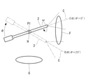
- the endoscope 2 is fixed to the subject and supported by the body wall at the position of the hole H which is the pivot point, and can swing around the pivot axis (first pivot axis) P1 passing through the pivot point H. Is.
- the pivot axis P1 extends anteroposteriorly to patient X from ventral to dorsal.
- the imaging region imaged by the endoscope 2 can move between the first region including the aorta F and the second region including the pelvis G. ..
- the endoscope 2 and the treatment tool 6 may be inserted into the subject via the trocca penetrating the hole H.
- a trocca is a tubular device that opens at both ends. In this case, the endoscope 2 is supported by the trocca at the position of the hole H.
- the endoscope system 10 includes an endoscope 2, a moving device 3 that holds the endoscope 2 and moves the endoscope 2 within a subject, and an endoscope.
- An endoscope processor 4 connected to 2 and processing the endoscope image E captured by the endoscope 2, a control device 1 connected to the moving device 3 and the endoscope processor 4 to control the moving device 3, and a control device 1. It is provided with a display device 5 connected to the endoscope processor 4 and displaying the endoscope image E.
- the endoscope 2 is a direct-view endoscope having an optical axis (optical axis) C coaxial with the longitudinal axis I of the endoscope 2, and is, for example, a rigid endoscope.
- the endoscope 2 has an image pickup element 2a, images the inside of the subject X, for example, the abdominal cavity, and acquires an endoscope image E (see FIGS. 5A to 6B) including the tip of the treatment tool 6.
- the image pickup element 2a is, for example, a three-dimensional camera provided at the tip of the endoscope 2, and captures a stereo image as an endoscope image E.
- the image sensor 2a is an image sensor such as a CCD (Charge Coupled Device) image sensor or a CMOS (Complementary Metal Oxide Sensor) image sensor, and converts the light received from a predetermined area into an electric signal by photoelectric conversion to obtain a predetermined area. Generate an image of.
- the stereo image which is the endoscope image E, is generated by image processing two images having parallax by an endoscope processor 4 or the like. In this case, the tip of the endoscope 2 has a stereo optical system.
- the endoscope image E is transmitted from the endoscope 2 to the endoscope processor 4, is subjected to necessary processing in the endoscope processor 4, is transmitted from the endoscope processor 4 to the display device 5, and is transmitted to the display device 5. Is displayed on the display screen 5a.
- the display device 5 is an arbitrary display such as a liquid crystal display or an organic EL display. The surgeon operates the treatment tool 6 inserted into the body while observing the endoscopic image E displayed on the display screen 5a.
- the display device 5 may include a voice device such as a speaker.
- a terminal used by the user to communicate with the control device 1 and the endoscope processor 4 through a communication network may be provided, and the endoscope image E may be displayed on the terminal.
- the terminal is not particularly limited, but may be a notebook computer, a laptop computer, a tablet computer, a smartphone, or the like.
- the moving device 3 includes a robot arm 3a (including an electric scope holder) that holds the endoscope 2 and three-dimensionally controls the position and posture of the endoscope 2.
- the moving device 3 has a plurality of joints 3b and 3c, and by the operation of the plurality of joints 3b and 3c, the endoscope 2 is moved with the pivot axis P1 as a fulcrum, and the position and posture of the endoscope 2 are three-dimensionally changed. Can be changed to.
- the processor 11 may be a single processor, a multi-processor or a multi-core processor.
- the processor 11 reads and executes the program stored in the storage unit 13.
- the memory 12 is, for example, a ROM (read-only memory) or a semiconductor memory including a RAM (Random Access Memory) area.
- the memory 12 may also store data necessary for processing by the processor 11 (that is, may operate as a “storage unit”), similarly to the storage unit 13 described later.
- the storage unit 13 is a non-temporary recording medium that can be read by a computer, and is, for example, a non-volatile recording medium including a semiconductor memory such as a hard disk or a flash memory.
- the storage unit 13 stores various programs including a follow-up control program (not shown) and an image control program (control program) 1a, and data necessary for processing by the processor 11.
- Some of the processes described later executed by the processor 11 are FPGA (Field Programmable Gate Array), SoC (System-on-a-Chip), ASIC (Application Specific Integrated Circuit), and PLC (Pro) dedicated Logic (Pro). It may be realized by a logic circuit, hardware, or the like.
- the storage unit 13 may be a server such as a cloud server connected to the control device 1 having a communication interface via a communication network instead of the recording medium built in the control device 1.
- the communication network may be, for example, a public line such as the Internet, a dedicated line, or a LAN (Local Area Network).
- the connection of the various devices may be either a wired connection or a wireless connection.
- the endoscope processor 4 that processes the endoscope image E may include the processor 11. That is, similarly to the processor 11 included in the control device 1, the endoscope processor 4 may include a processor, a dedicated logic circuit, or hardware, and may perform the processing described later in the same manner as the processor 11.
- the endoscope processor 4 and the control device 1 may be integrated.
- the endoscope processor 4 and the control device 1 may each be provided with one or more processors.
- the configuration of any one of the at least one processor 11, the memory 12, the storage unit 13, the input interface 14, the output interface 15, and the user interface 16 included in the control device 1 is separate from the endoscope processor 4 and the control device 1. It may be further provided in the terminal used by the user. Further, the control device 1 may be integrated with the mobile device 3.
- the input interface 14 and the output interface 15 are connected to the endoscope processor 4.
- the control device 1 can acquire the endoscope image E from the endoscope 2 via the endoscope processor 4, and displays the endoscope image E on the display device 5 via the endoscope processor 4. Can be output.
- the input interface 14 is directly connected to the endoscope 2 so that the control device 1 can directly acquire the endoscope image E from the endoscope 2 and output the endoscope image E directly to the display device 5.
- the output interface 15 may be directly connected to the display device 5. Further, the input interface 14 and the output interface 15 are connected to the mobile device 3.
- the control device 1 acquires information on the rotation angles of the joints 3b and 3c detected by the angle sensor 3d from the moving device 3, and transmits a control signal for driving the joints 3b and 3c to the moving device 3.
- the user interface 16 has an input device such as a button, a mouse, a keyboard, and a touch panel for a user such as an operator to input to the user interface 16, and receives input from the user. Further, the user interface 16 has means for the user to switch between the manual mode and the autonomous mode, which will be described later, for example, a switch. Further, the user interface 16 is configured to be able to receive the first instruction and the second instruction of the user. The first instruction and the second instruction are instructions for causing the control device 1 to register the position information and the rotation angle information described later. For example, the user interface 16 has a button operated by an operator, and receives a first instruction when the button is operated for the first time, and receives a second instruction when the button is operated for the second time.
- the processor 11 can operate in either manual mode or autonomous mode.
- the manual mode is a mode that allows a user such as an operator to operate the endoscope 2.
- the operator can manually grasp the base end portion of the endoscope 2 and move the endoscope 2 manually.
- the operator can remotely control the endoscope 2 by using the operating device connected to the moving device 3.
- the operating device can include buttons, a joystick, a touch panel, and the like.
- the autonomous mode is a mode in which the endoscope 2 is automatically made to follow the treatment tool 6 by controlling the moving device 3 based on the position of the treatment tool 6 reflected in the endoscope image E.
- the processor 11 acquires the three-dimensional position of the tip of the treatment tool 6 from the endoscope image E, and sets the three-dimensional position of the tip of the treatment tool 6 and the predetermined position within the field of view of the endoscope 2.
- the moving device 3 is controlled based on the three-dimensional position of the target point.
- the target point is, for example, a point on the optical axis C corresponding to the center point of the endoscopic image E.
- the control device 1 controls the movement of the endoscope 2 and causes the treatment tool 6 to follow the endoscope 2 so that the tip of the treatment tool 6 is arranged at the center point in the endoscope image E. ..
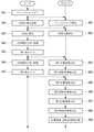
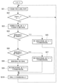
- the processor 11 executes the control method shown in FIGS. 3A and 3B according to the image control program 1a read into the memory 12, so that the endoscope image E displayed on the display screen 5a is displayed. Control the angle of rotation.
- the control method includes the step SB2 for setting the initial position of the endoscope 2, the first position information of the first region in the subject, and the first rotation.
- Steps SB3 and SB4 for determining the angle information
- steps SB5 and SB6 for determining the second position information and the second rotation angle information of the second region in the subject, and the third position information of the third region in the subject.
- steps SB7 and SB8 for calculating the third rotation angle information
- the step SB9 for storing the position information and the rotation angle information in the storage unit 13, and the inside according to the current image pickup area currently imaged by the endoscope 2.
- steps SC4 to SC9 for rotating the endoscope image E and steps SC10 for outputting the rotated endoscope image E to the display device 5.
- steps SB2 to SB9 are performed in manual mode
- steps SC3 to SC10 are performed in autonomous mode.
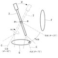
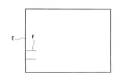
- the operator places the endoscope 2 at a position (point O) where the aorta F is imaged from the front, and the aorta F is desired in the endoscopic image E.
- the rotation angle ⁇ of the endoscope 2 around the optical axis C is adjusted so as to be arranged at the rotation angle of (SA4).
- the angle of rotation of the aorta F here is a position in the circumferential direction around the center point of the endoscopic image E.
- the angle of rotation ⁇ is adjusted so that the aorta F is arranged horizontally in the endoscopic image E.
- the operator inputs the first instruction to the user interface 16 (SA5).
- the surgeon rotates the endoscope 2 from the O point around the pivot axis P1 while maintaining the angle of rotation ⁇ adjusted at the O point, so that the entire aorta F is endoscopeed. Observe by 2.
- the aorta F rotates and moves within the endoscope image E.
- Point B is the end point of the range in which the aorta F is observed in the endoscopic image E.
- the storage unit 13 stores a trained model 1b in which the correspondence between the image including the specific tissue and the type of the specific tissue is machine-learned.
- the processor 11 transfers the aorta F in the endoscopic image E to the aorta F in the first reference endoscopic image with respect to the endoscopic image E acquired at another position ⁇ included in the first position information.
- the amount of rotation ⁇ of the endoscopic image E required to match with is calculated.
- the processor 11 calculates the target rotation angle ⁇ t at another position ⁇ by adding the rotation amount ⁇ to the first reference rotation angle.
- the calculated target rotation angle ⁇ t represents the amount of rotation of the endoscopic image E required to horizontally arrange the aorta F in the endoscopic image E at another position ⁇ .
- FIG. 5C shows the endoscopic image E of FIG. 5B rotated by the target angle ⁇ t at point B.
- the operator places the endoscope 2 at the position (point D) where the pelvis G is imaged.
- the pelvis G may be placed at an inappropriate position in the endoscopic image E, as shown in FIG. 6A.
- the surgeon adjusts the angle of rotation ⁇ around the optical axis C of the endoscope 2 so that the pelvis G is arranged at a desired angle of rotation in the endoscope image E (SA6), and the user interface 16 is second. Enter the instructions (SA7).
- SA6 desired angle of rotation in the endoscope image E
- SA7 desired angle of rotation in the endoscope image E
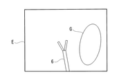
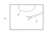
- the angle of rotation ⁇ is adjusted so that the pelvis G is positioned upward in the endoscopic image E.
- step SB5 the processor 11 recognizes the pelvis G in the endoscope image E using the trained model 1b, and the endoscope 2 in which the pelvis G is included in the endoscope image E.
- the range of the position ⁇ of is determined as the second position information. That is, the second region is a region between the points D and A.
- the processor 11 sets the position ⁇ of the endoscope 2 at the time when the second instruction is received as the second position information without going through the processing by the trained model 1b. You may. That is, the second position information is determined at the user's desired timing and place.
- the target rotation angle ⁇ t that gradually changes from 100 ° to ⁇ 10 ° as the position ⁇ changes from point B to point A is calculated.
- the aorta F is kept horizontal. For example, when the endoscope 2 swings by 20 ° around the pivot axis P1 from the point O to the point B, the endoscope image E rotates from 0 ° to ⁇ 10 °.
- the pelvis G is maintained upward. For example, when the endoscope 2 swings by 20 ° around the pivot axis P1 from the point A to the point D, the endoscope image E rotates from 100 ° to 90 °.
- the processor 11 determines that the current imaging region is included in the third region (NO of SC4 and NO of SC6). SC8). Next, the processor 11 rotates the endoscope image E in the plane of the endoscope image E based on the third rotation angle information stored in the storage unit 13 (SC9). Specifically, the processor 11 reads out the rotation angle of the current position ⁇ from the storage unit 13, and rotates the endoscope image E by the rotation angle by image processing. Next, the processor 11 outputs the rotated endoscope image E from the control device 1 to the display device 5 and displays it on the display screen 5a (SC10).
- SC9 third rotation angle information stored in the storage unit 13
- the control method according to the present embodiment includes the step SB2 for determining the initial position of the endoscope 2, the first position information of the first region in the subject, and the first rotation. Steps SB3, SB4'to determine the angle information, steps SB5, SB6'to determine the second position information and the second rotation angle information of the second region in the subject, and the third region of the third region in the subject.
- the processor 11 uses the pelvic G in the endoscopic image E as the aorta G in the second reference endoscopic image for the endoscopic image E acquired at another position ⁇ included in the second position information.
- the amount of rotation ⁇ of the endoscopic image E required to match with is calculated.
- the processor 11 calculates the target rotation angle ⁇ t of the endoscope 2 at another position ⁇ by adding the rotation amount ⁇ to the second reference rotation angle.
- the endoscope 2 in the autonomous mode, is rotated to the target rotation angle ⁇ t according to the position ⁇ of the current imaging region, whereby the endoscope 2 is rotated.
- the vertical direction of the endoscope image E is automatically adjusted.
- the endoscope 2 has a target rotation angle ⁇ t in which the specific tissues F and G are arranged at a predetermined rotation angle. Is automatically rotated.
- the endoscope 2 is automatically rotated to an appropriate target rotation angle ⁇ t estimated from the first and second rotation angle information. ..
- the present embodiment by rotating the endoscope image E by rotating the endoscope 2 around the optical axis C, it is possible to eliminate the image processing for rotating the endoscope image E.
- the load on the processor 11 can be reduced.
- the user can intuitively recognize the vertical direction of the endoscope image E by visually confirming the rotation angle ⁇ of the portion of the endoscope 2 arranged outside the body.
- step SB9 the processor 11 calculates the current position ⁇ of the endoscope 2 (SC1).
- the processor 11 executes steps SC1 to SC4, SC5', SC6, SC7', SC8, SC9'.
- the processor 11 When the endoscope 2 rotates to the target rotation angle ⁇ t without the rotation angle ⁇ reaching the limit angle (NO of SC11), the processor 11 outputs the rotated endoscope image E to the display device 5 (SC10). .. On the other hand, when the rotation angle ⁇ reaches the limit angle before reaching the target rotation angle ⁇ t (YES of SC11), the processor 11 stops the rotation of the endoscope 2 at the limit angle, and then the target rotation angle ⁇ t. The endoscopic image E is rotated by image processing by an angle of rotation that is insufficient (SC12), and the rotated endoscopic image E is output to the display device 5 (SC10).
- the perspective endoscope 2 has a long insertion portion 2b having a longitudinal axis I and inserted into a subject, and an imaging portion 2c including an image pickup element 2a and connected to the base end of the insertion portion 2b. Have. Due to the rotation of the rotary joint 3c, the insertion portion 2b and the imaging portion 2c rotate integrally around the longitudinal axis I. In the case of a separate perspective mirror, the camera head (imaging unit 2c) and the optical viewing tube (inserting unit 2b) have different rotation angle information, but in this modification, the camera head and the optical viewing tube are integrated. Processing is performed as common rotation angle information by rotating the camera.
- the posture ⁇ of the endoscope 2 is the angle of rotation around the longitudinal axis I, and corresponds to the posture of the visual axis C with respect to the longitudinal axis I.
- the processor 11 determines the first position information and the first rotation angle information (SB3, SB4), and further issues the first instruction. Information on the first posture of the endoscope 2 at the time of acceptance is retained.
- the processor 11 determines the second position information and the second rotation angle information (SB5, SB6), and further issues the second instruction. Information on the second posture of the endoscope 2 at the time of acceptance is retained.
- the processor 11 stores the first posture and the second posture in the storage unit 13 in addition to the position information and the rotation angle information.
- the rotation angle ⁇ of the endoscope 2 representing the position of the imaging region
- the target rotation angle ⁇ t of the endoscope image E at each rotation angle ⁇ and the first posture of the endoscope 2 corresponding to each imaging region.
- Data including the second posture and the second posture are generated in the storage unit 13.
- the processor 11 controls the position and posture of the endoscope 2 by controlling the moving device 3, and causes the endoscope 2 to follow the tip of the treatment tool 6 (SC3').
- the processor 11 controls the position and orientation of the endoscope 2 based on the first and second position information stored in the storage unit 13 and the first and second postures, so that the imaging region becomes a second position.
- the posture ⁇ of the endoscope 2 is controlled to the first posture
- the posture ⁇ of the endoscope 2 is controlled to the second posture.
- the processor 11 rotates the endoscope image E by the target rotation angle ⁇ t by image processing according to the current imaging region (SC4 to SC9).
- the imaging region moves due to the rotation of the endoscope 2 around the longitudinal axis I. Therefore, it is difficult to control the vertical direction of the endoscope image E only by the control method of the second embodiment in which the endoscope image E is rotated by the rotation of the endoscope 2.
- the first posture of the endoscope 2 when imaging the first region and the second posture of the endoscope 2 when imaging the second region are stored. ..
- the autonomous mode when the first region is imaged, the posture of the endoscope 2 is controlled to the first posture, and the vertical direction of the endoscope image E is adjusted by rotation by image processing.
- the autonomous mode when the second region is imaged, the posture of the endoscope 2 is controlled to the second posture, and the vertical direction of the endoscope image E is adjusted by rotation by image processing. Thereby, the vertical direction of the endoscope image E acquired by the perspective endoscope 2 can be appropriately controlled.
- the endoscope 2 includes a long insertion portion 2b to be inserted into the subject, and a bending portion 2d provided at the tip of the insertion portion 2b and capable of bending in a direction intersecting the longitudinal axis I of the insertion portion 2b.
- a bending portion 2d provided at the tip of the insertion portion 2b and capable of bending in a direction intersecting the longitudinal axis I of the insertion portion 2b.
- the control method executed by the processor 11 in this modification includes steps SB2', SB3 to SB9, and processes SC3', SC4 to SC10, as in the first modification.
- the rotation direction and the rotation angle of the curved portion 2d are used instead of the rotation angle ⁇ around the longitudinal axis I.
- the processor 11 sets the current bending direction and bending angle of the bending portion 2d as the initial posture. Then, in the step SB9, the processor 11 stores the bending direction and the bending angle of the bending portion 2d at the time when the first instruction is received in the storage unit 13 as the first posture, and bends at the time when the second instruction is received. The bending direction and bending angle of the section 2d are stored in the storage section 13 as the second posture.
- the processor 11 controls the position and posture of the endoscope 2 based on the first and second position information stored in the storage unit 13 and the first and second postures. Thereby, when the imaging region is included in the first region, the bending direction and bending angle of the bending portion 2d are controlled to the first posture, and when the imaging region is included in the second region, the bending direction and bending of the bending portion 2d are controlled. The angle is controlled to the second posture (SC3').
- the imaging region rotates and moves by the rotation of the endoscope 2 according to the bending direction and the bending angle of the curved portion 2d. Therefore, it is difficult to control the vertical direction of the endoscope image E by the control method of the second embodiment in which the endoscope image E is rotated by the rotation of the endoscope 2.
- the posture of the endoscope 2 in the autonomous mode, when the first region is imaged, the posture of the endoscope 2 is controlled to the first posture stored in the manual mode, and the endoscope image is displayed.
- the vertical direction of E is adjusted by rotation by image processing.
- the posture of the endoscope 2 in the autonomous mode, when the second region is imaged, the posture of the endoscope 2 is controlled to the second posture stored in the manual mode, and the vertical direction of the endoscope image E is adjusted by rotation by image processing. To. Thereby, the vertical direction of the endoscope image E acquired by the endoscope 2 having the curved portion 2d can be appropriately controlled.
- the processor 11 calculates the third rotation angle information in the manual mode and stores it in the storage unit 13, but instead, as shown in FIGS. 13A and 13B.
- the processor 11 may calculate the third rotation angle information in real time during the execution of the autonomous mode (SC13).
- SC13 autonomous mode
- the processor 11 does not determine and store the third position information and the third rotation angle information in the manual mode.
- the third region means a region other than the first region and the second region.
- the processor 11 determines that the endoscope 2 is included.
- the target rotation angle ⁇ t or ⁇ t at the current position ⁇ may be calculated in real time based on the current position ⁇ , the first position information, the first rotation angle information, the second position information, and the second rotation angle information (SC13). ). Further, when the current imaging region is included in either the first region or the second region (not included in the third region), the processor 11 does not calculate the target rotation angle ⁇ t or ⁇ t in real time, and the first region is not calculated. It suffices to match the rotation angle information or the second rotation angle information.
- the amount of position information and rotation angle information stored in the storage unit 13 in the manual mode can be reduced, and only the third position information and the third rotation angle information required when operating the autonomous mode can be reduced. Is sufficient to calculate, so the load on the system is reduced.
- the processor 11 has the first position information or the second position information stored in advance, or the first rotation angle information or the second rotation.
- the angle information may be updated with the current position information and the angle of rotation information.
- the endoscope 2 is moved after the update and it is determined that the current imaging region is included in the first region or the second region, the updated first position information, second position information, and first rotation angle information are obtained.
- the second angle of rotation information can be used.
- the user may give an update instruction from the user interface 16. By doing so, even if a part of the patient's body is deformed due to pneumoperitoneum or posture adjustment, it is possible to update the position information and rotation angle information to the correct information according to the current situation. Become.
- the processor 11 recognizes a specific tissue in the endoscopic image E and determines each position information and each rotation angle information based on the recognized specific tissue.
- each position information and each rotation angle information may be determined based on the position ⁇ and the rotation angle ⁇ of the endoscope 2 at the time when each instruction is received. That is, in the manual mode, the operator arranges the endoscope 2 at a desired position at a desired rotation angle ⁇ , and inputs the first instruction.
- the processor 11 determines the peripheral range of the position ⁇ of the endoscope 2 at the time when the user interface 16 receives the first instruction as the first position information, and the processor 11 determines the range around the position ⁇ of the endoscope 2 at the time when the user interface 16 receives the second instruction.
- the rotation angle ⁇ of the endoscope 2 is determined as the first rotation angle information.
- the surgeon places the endoscope 2 at another desired position at a desired angle of rotation ⁇ and inputs a second instruction.
- the processor 11 determines the peripheral range of the position ⁇ of the endoscope 2 at the time when the user interface 16 receives the second instruction as the second position information, and the processor 11 determines the range at the time when the user interface 16 receives the second instruction.
- the rotation angle ⁇ of the endoscope 2 is determined as the second rotation angle information.
- the operator can register any region in the subject as the first region and the second region, and can determine the position information and the angle of rotation information according to the operator's sense. become. Further, even when the specific tissues are not included in the first and second regions, the position information and the rotation angle information of the first and second regions are arbitrarily determined and stored without processing the trained model 1b. be able to.
- the processor 11 has first and second position information and first and first positions based on the specific tissues F and G in the endoscopic image E as described in the first to third embodiments and their variants. After determining the two rotation angle information, the position information and the rotation angle information of any region different from the first and second regions may be further determined based on the instruction of the operator.
- the specific tissues are the aorta F and the pelvis G, but the specific tissues may be any organ or tissue having anatomical characteristics, for example, the uterus. You may.
- the position information and the rotation angle information of the two regions are stored, but instead, the position information and the rotation angle information of three or more regions may be stored. .. This makes it possible to improve the accuracy when calculating the position information and the rotation angle information based on the information stored in advance.
- the position ⁇ of the endoscope 2 representing the position of the imaging region is represented by a two-dimensional polar coordinate system with the pivot point H as the origin. It may be expressed in a three-dimensional polar coordinate system. That is, even if the endoscope 2 is swingably supported around the second pivot axis P2 passing through the pivot point H and orthogonal to the first pivot axis P1, and the position of the imaging region is expressed as ( ⁇ 1, ⁇ 2). good.
- ⁇ 1 is a rotation angle around the first pivot axis P1
- ⁇ 2 is a rotation angle around the second pivot axis P2.
- each of the first position information, the second position information, and the third position information is three-dimensional information including the rotation angles ⁇ 1 and ⁇ 2.
- the position of the imaging region may be represented by another type of coordinate system instead of the polar coordinate system.
- the position of the imaging region may be represented by a Cartesian coordinate system originating from the hole H.
- the coordinate system of the position ⁇ of the imaging region is a global coordinate system fixed with respect to the subject, but instead of this, with respect to the tip of the endoscope 2. It may be a relative coordinate system.
- the first and second position information is determined in the manual mode and stored in the storage unit 13, but instead, the first and second position information are used for surgery. It may be stored in advance in the storage unit 13. Before surgery, a CT image of a range including the treatment site, for example, a CT image of the abdomen may be acquired. By deconvolution processing a large number of CT images, a three-dimensional image in the abdominal cavity is generated. Based on such a preoperative three-dimensional image, the first and second position information may be determined and stored in the storage unit 13 before the operation. In this case, in the manual mode, steps SB4 and SB6 are omitted. According to this configuration, the amount of calculation of the processor 11 in the manual mode can be reduced.
- the processor 11 in the manual mode, includes a first endoscope image E, which is an endoscope image E of the first region, and an endoscope image E, which is an image of the second region.
- a certain second endoscope image and may be stored in the storage unit 13.
- the processor 11 stores one or more endoscopic images E in which the aorta F is recognized in the storage unit 13 as a first endoscopic image.
- the processor 11 stores one or more endoscopic images E in which the pelvis G is recognized in the storage unit 13 as a second endoscopic image.
- the processor 11 determines whether the current imaging region is included in the first, second, or third region based on the first endoscope image and the second endoscope image. You may. That is, the processor 11 compares the current endoscope image E with the first endoscope image and the second endoscope image. Then, the processor 11 determines that the current imaging region is included in the first region when there is a first endoscope image that is the same as or similar to the current endoscope image E, and the current endoscope image. When there is a second endoscopic image that is the same as or similar to E, it is determined that the current imaging region is included in the second region.
- the processor 11 when the endoscopic image E contains a specific tissue, the processor 11 reads and reads information about the rotation angle of the specific tissue from the database 1c stored in the storage unit 13.
- the endoscope image E may be rotated based on the information regarding the angle of rotation.
- the angle of rotation is the angle around the center point of the endoscopic image E. According to this configuration, the endoscope image E can be rotated so that the specific tissue in the endoscope image E is arranged at a predetermined rotation angle.
- the processor 11 recognizes the specific tissue in the endoscope image E, reads the rotation angle of the specific tissue from the database 1c, and rotates the endoscope image E so that the specific tissue is arranged at the rotation angle.
- the uterus J which is a specific tissue
- 90 ° corresponding to the 12 o'clock position is registered as the rotation angle of the uterus J in the database 1c. Will be done.
- the processor 11 rotates the endoscopic image E so that the recognized uterus J is positioned at 90 °.
- the vertical direction of the endoscopic image E is automatically adjusted so that the uterus J is arranged at the position of 90 °.
- the rotation of the endoscope image E is controlled based on the specific tissues F and G in the endoscope image E, but in addition to this, the endoscope image E is controlled.
- the rotation of the endoscopic image E may be controlled based on the treatment tool 6 inside.
- the processor 11 has a first rotation mode that controls the rotation of the endoscope image E based on the specific tissues F and G, and a second rotation mode that controls the rotation of the endoscope image E based on the treatment tool 6. It is possible to operate with.
- a user such as an operator can switch between the first rotation mode and the second rotation mode by using the user interface 16.
- the processor 11 detects the angle of the treatment tool 6 in the current endoscope image E, and the angle of the treatment tool 6 is equal to a predetermined target angle by rotation or image processing of the endoscope 2.
- the endoscope image E is rotated so as to be so that the rotated endoscope image E is output to the display device 5 and displayed on the display screen 5a.
- the angle of the treatment tool 6 is, for example, the angle of the longitudinal axis of the shaft of the treatment tool 6 with respect to the horizontal line of the endoscopic image E.
- the angle of the treatment tool 6 in the endoscope image E displayed on the display screen 5a is appropriate. Is. However, the angle of the treatment tool 6 in the endoscope image E changes when the surgeon moves the treatment tool 6 or changes the posture of the endoscope 2 following the treatment tool 6.
- the surgeon can display the treatment tool 6 in the endoscopic image E at a target angle on the display screen 5a by switching from the first rotation mode to the second rotation mode as needed.
- the operator holds the treatment tool 6 in his hand and manually operates the treatment tool 6, but instead, as shown in FIGS. 14A and 14B, the treatment tool 6 is used. , May be held and controlled by a second mobile device 31 different from the mobile device 3.
- the control device 1 acquires the position information of the endoscope 2 and the treatment tool 6 from the moving device 3 for moving the endoscope 2 and the second moving device 31 for moving the treatment tool 6, respectively. good.
- the second moving device 31 holds the treatment tool 6 by a robot arm or an electric holder, and changes the position and posture of the treatment tool 6 three-dimensionally according to the control by the control device 101.
- the treatment tool 6 may be connected to the tip of the robot arm and integrated with the robot arm, and as shown in FIG. 14B, the treatment tool 6 is separate from the robot arm and is gripped by the robot arm. It may have been done.
- Control device 11 Processor 12 Memory 13 Storage unit, Recording medium 14 Input interface 15 Output interface 16 User interface 1a Image control program 1b Learned model 1c Database 2 Endoscope 2a Image pickup element 3 Mobile device 3a Robot arm 3b, 3c Joint 3d Angle sensor 4 Endoscope processor 5 Display device 5a Display screen 6 Treatment tools A, B, D, O Position C Optical axis, visual axis P1 1st pivot axis P2 2nd pivot axis E Endoscopic image F Aortic, 1st Specific tissue G pelvis, 2nd specific tissue H hole
Landscapes
- Health & Medical Sciences (AREA)
- Life Sciences & Earth Sciences (AREA)
- Engineering & Computer Science (AREA)
- Surgery (AREA)
- Physics & Mathematics (AREA)
- Public Health (AREA)
- Animal Behavior & Ethology (AREA)
- General Health & Medical Sciences (AREA)
- Heart & Thoracic Surgery (AREA)
- Veterinary Medicine (AREA)
- Molecular Biology (AREA)
- Medical Informatics (AREA)
- Biomedical Technology (AREA)
- Nuclear Medicine, Radiotherapy & Molecular Imaging (AREA)
- Pathology (AREA)
- Biophysics (AREA)
- Optics & Photonics (AREA)
- Radiology & Medical Imaging (AREA)
- Signal Processing (AREA)
- General Physics & Mathematics (AREA)
- Robotics (AREA)
- Human Computer Interaction (AREA)
- Multimedia (AREA)
- Theoretical Computer Science (AREA)
- Computer Vision & Pattern Recognition (AREA)
- Mechanical Engineering (AREA)
- Astronomy & Astrophysics (AREA)
- Endoscopes (AREA)
- Instruments For Viewing The Inside Of Hollow Bodies (AREA)
Abstract
内視鏡システム(10)は、内視鏡(2)と、内視鏡(2)を移動させる移動装置(3)と、記憶部と、プロセッサを有する制御装置(4)とを備える。記憶部は、被検体内の第1領域の第1位置情報および第1回転角情報と、被検体内の第2領域の第2位置情報および第2回転角情報とを記憶する。第1回転角情報は、第1領域の内視鏡画像の回転角を規定する情報であり、第2回転角情報は、第2領域の内視鏡画像の回転角を規定する情報である。プロセッサは、被検体内の第3領域の第3回転角情報を第1および第2位置情報、第1および第2回転角情報ならびに第3領域の第3位置情報に基づいて算出し、現在の撮像領域が第3領域に含まれる場合、第3回転角情報に基づいて内視鏡画像を回転させ、回転された内視鏡画像を表示装置に出力する。
Description
本発明は、内視鏡システム、制御装置、制御方法および記録媒体に関するものである。
本出願は、2020年9月10日にアメリカ合衆国に仮出願された米国特許仮出願第63/076,408号に基づいて優先権を主張し、その内容をここに援用する。
本出願は、2020年9月10日にアメリカ合衆国に仮出願された米国特許仮出願第63/076,408号に基づいて優先権を主張し、その内容をここに援用する。
従来、電動のホルダを制御することによって、ホルダに保持された内視鏡を移動させる内視鏡システムが知られている(例えば、特許文献1参照。)
特許文献1の内視鏡システムは、手動モードにおいて操作者が内視鏡を移動させている間のホルダの各関節の回転角度の時系列変化を記憶し、自動復帰モードにおいて、各関節の回転角度の時系列変化を逆再生する。これにより、内視鏡は、手動モードにおける移動軌跡を逆方向に移動し、初期の位置および姿勢に自動的に復帰する。
特許文献1の内視鏡システムは、手動モードにおいて操作者が内視鏡を移動させている間のホルダの各関節の回転角度の時系列変化を記憶し、自動復帰モードにおいて、各関節の回転角度の時系列変化を逆再生する。これにより、内視鏡は、手動モードにおける移動軌跡を逆方向に移動し、初期の位置および姿勢に自動的に復帰する。
術者が表示装置に表示される内視鏡画像を観察しながら患部の手術を行うとき、表示装置上の内視鏡画像の上下方向が重要である。内視鏡画像の上下方向は、内視鏡画像内の被写体の回転角を示し、別の表現では天地方向とも言う。内視鏡画像の上下方向に応じて臓器の配置および組織の見え方が異なる。したがって、術者が表示装置上の内視鏡画像内の臓器および組織を正確に認識することができるようにするために、適切な上下方向の内視鏡画像が表示装置に表示されること
が望ましい。
が望ましい。
しかし、体内での内視鏡の移動に伴って内視鏡画像の上下方向は変化する。さらに、術者にとって望ましい内視鏡画像の上下方向は観察位置や手技内容に応じて異なる。特許文献1の内視鏡システムは、手動モードにおける移動軌跡を再現するのみで、内視鏡の位置または観察位置に応じて内視鏡画像の上下方向を調整する機能を有しない。したがって、内視鏡画像の上下方向を調整するために、術者は、操作中の処置具から一旦手を放して処置を中断し、内視鏡を手動で操作して内視鏡の姿勢を調整する必要がある。
本発明は、上述した事情に鑑みてなされたものであって、内視鏡画像の上下方向を自動的に調整することができる内視鏡システム、制御装置、制御方法および記録媒体を提供することを目的とする。
本発明の一態様は、被検体(患者体腔内)内に挿入され該被検体内の内視鏡画像を取得する内視鏡と、該内視鏡を保持し該内視鏡を移動させる移動装置と、記憶部と、少なくとも1つのプロセッサを有する制御装置と、を備え、前記記憶部が、前記被検体内の第1領域の第1位置情報および第1回転角情報と、前記被検体内の前記第1領域とは異なる第2領域の第2位置情報および第2回転角情報と、を記憶し、前記第1回転角情報は、前記第1領域の前記内視鏡画像の回転角を規定する情報であり、前記第2回転角情報は、前記第2領域の前記内視鏡画像の回転角を規定する情報であり、前記少なくとも1つのプロセッサは、前記被検体内の第3領域の第3回転角情報を前記第1位置情報、前記第1回転角情報、前記第2位置情報、前記第2回転角情報および前記第3領域の第3位置情報に基づいて算出し、前記第3領域は前記第1および第2領域とは異なる領域であり、前記内視鏡によって現在撮像されている現在の撮像領域が前記第3領域に含まれる場合、前記第3回転角情報に基づいて前記内視鏡画像を回転させ、回転された前記内視鏡画像を表示装置に出力する、内視鏡システムである。
本発明の他の態様は、内視鏡によって取得され表示装置に表示される内視鏡画像を制御する制御装置であって、記憶部と、少なくとも1つのプロセッサと、を備え、前記記憶部が、被検体内の第1領域の第1位置情報および第1回転角情報と、前記被検体内の前記第1領域とは異なる第2領域の第2位置情報および第2回転角情報と、を記憶し、前記第1回転角情報は、前記第1領域の前記内視鏡画像の回転角を規定する情報であり、前記第2回転角情報は、前記第2領域の前記内視鏡画像の回転角を規定する情報であり、前記少なくとも1つのプロセッサは、前記被検体内の第3領域の第3回転角情報を前記第1位置情報、前記第1回転角情報、前記第2位置情報、前記第2回転角情報および前記第3領域の第3位置情報に基づいて算出し、前記第3領域は前記第1および第2領域とは異なる領域であり、前記内視鏡によって現在撮像されている現在の撮像領域が前記第3領域に含まれる場合、前記第3回転角情報に基づいて前記内視鏡画像を回転させ、回転された前記内視鏡画像を表示装置に出力する、制御装置である。
本発明の他の態様は、内視鏡によって取得され表示装置に表示される内視鏡画像を、被検体内の第1領域の第1位置情報および第1回転角情報と前記被検体内の前記第1領域とは異なる第2領域の第2位置情報および第2回転角情報とを用いて制御する制御方法であって、前記第1回転角情報は、前記第1領域の前記内視鏡画像の回転角を規定する情報であり、前記第2回転角情報は、前記第2領域の前記内視鏡画像の回転角を規定する情報であり、前記被検体内の第3領域の第3回転角情報を前記第1位置情報、前記第1回転角情報、前記第2位置情報、前記第2回転角情報および前記第3領域の第3位置情報に基づいて算出し、前記第3領域は前記第1および第2領域とは異なる領域である、工程と、前記内視鏡によって現在撮像されている現在の撮像領域が前記第3領域に含まれる場合、前記第3回転角情報に基づいて前記内視鏡画像を回転させる工程と、回転された前記内視鏡画像を表示装置に出力する工程と、を含む制御方法である。
本発明の他の態様は、上記の制御方法をコンピュータに実行させるための制御プログラムを記録した、コンピュータにより読み取り可能な非一時的な記録媒体である。
本発明によれば、被検体内の観察位置に応じて適切な上下方向の内視鏡画像を操作者に提供することができるという効果を奏する。
(第1実施形態)
本発明の第1実施形態に係る内視鏡システム、制御装置、制御方法および記録媒体について図面を参照して説明する。
図1Aに示されるように、本実施形態に係る内視鏡システム10は、内視鏡2および1以上の処置具6を被検体である患者Xの体内に挿入し、処置具6を内視鏡2によって観察しながら処置具6で処置部位を処置する手術に使用され、例えば、腹腔鏡下手術に使用される。
本発明の第1実施形態に係る内視鏡システム、制御装置、制御方法および記録媒体について図面を参照して説明する。
図1Aに示されるように、本実施形態に係る内視鏡システム10は、内視鏡2および1以上の処置具6を被検体である患者Xの体内に挿入し、処置具6を内視鏡2によって観察しながら処置具6で処置部位を処置する手術に使用され、例えば、腹腔鏡下手術に使用される。
図1Bに示されるように、内視鏡2は、体壁に形成された穴Hを経由して被検体内、例えば腹腔内に挿入される。これにより、内視鏡2は、被検体に対して固定されピボット点である穴Hの位置において体壁によって支持され、ピボット点Hを通るピボット軸(第1ピボット軸)P1回りに揺動可能である。図1Aおよび図1Bに示される腹腔鏡下手術において、ピボット軸P1は、腹側から背側へ向かう患者Xの前後方向に延びている。ピボット軸P1回りの内視鏡2の揺動によって、内視鏡2によって撮像される撮像領域は、大動脈Fを含む第1領域と骨盤Gを含む第2領域との間で移動することができる。
内視鏡2および処置具6は、穴Hを貫通するトロッカ内を経由して被検体内に挿入されてもよい。トロッカは、両端において開口する筒状の器具である。この場合、内視鏡2は、穴Hの位置においてトロッカによって支持される。
内視鏡2および処置具6は、穴Hを貫通するトロッカ内を経由して被検体内に挿入されてもよい。トロッカは、両端において開口する筒状の器具である。この場合、内視鏡2は、穴Hの位置においてトロッカによって支持される。
図1Aおよび図2に示されるように、内視鏡システム10は、内視鏡2と、内視鏡2を保持し内視鏡2を被検体内で移動させる移動装置3と、内視鏡2と接続され内視鏡2によって撮像された内視鏡画像Eを処理する内視鏡プロセッサ4と、移動装置3および内視鏡プロセッサ4と接続され移動装置3を制御する制御装置1と、内視鏡プロセッサ4と接続され内視鏡画像Eを表示する表示装置5とを備える。
内視鏡2は、内視鏡2の長手軸Iと同軸の視軸(光軸)Cを有する直視型内視鏡であり、例えば硬性鏡である。内視鏡2は、撮像素子2aを有し、被検体X内、例えば腹腔内を撮像し、処置具6の先端を含む内視鏡画像E(図5Aから図6B参照。)を取得する。撮像素子2aは、例えば内視鏡2の先端部に設けられた3次元カメラであり、ステレオ画像を内視鏡画像Eとして撮像する。撮像素子2aは、CCD(Charge Coupled Device)イメージセンサまたはCMOS(Complementary Metal Oxide Semiconductor)イメージセンサなどのイメージセンサであり、所定領域から受光した光を光電変換により電気信号に変換することで、所定領域の画像を生成する。内視鏡画像Eであるステレオ画像は、視差を有する2つの画像を内視鏡プロセッサ4等によって画像処理することで生成される。この場合、内視鏡2の先端部は、ステレオ光学系を有する。
内視鏡画像Eは、内視鏡2から内視鏡プロセッサ4に送信され、内視鏡プロセッサ4において必要な処理が施され、内視鏡プロセッサ4から表示装置5に送信され、表示装置5の表示画面5aに表示される。表示装置5は、液晶ディスプレイ、有機ELディスプレイ等の任意のディスプレイである。術者は、表示画面5aに表示される内視鏡画像Eを観察しながら体内に挿入された処置具6を操作する。表示装置5は、スピーカ等の音声装置を備えていてもよい。
表示装置5以外に、ユーザによって使用され制御装置1および内視鏡プロセッサ4と通信ネットワークを通じて通信する端末が設けられ、端末に内視鏡画像Eが表示されてもよい。端末は、特に限定しないが、ノート型コンピュータ、ラップトップ型コンピュータ、タブレット型コンピュータまたはスマートフォンなどである。
表示装置5以外に、ユーザによって使用され制御装置1および内視鏡プロセッサ4と通信ネットワークを通じて通信する端末が設けられ、端末に内視鏡画像Eが表示されてもよい。端末は、特に限定しないが、ノート型コンピュータ、ラップトップ型コンピュータ、タブレット型コンピュータまたはスマートフォンなどである。
移動装置3は、内視鏡2を保持し内視鏡2の位置および姿勢を3次元的に制御するロボットアーム3a(電動スコープホルダを含む)を備える。移動装置3は、複数の関節3b,3cを有し、複数の関節3b,3cの動作によって、ピボット軸P1を支点として内視鏡2を移動させ内視鏡2の位置および姿勢を3次元的に変更することができる。
図1Cに示されるように、関節3cは、内視鏡2を長手軸I回りに回転させる回転関節であり、例えばロボットアーム3aの先端部に設けられている。関節3cの回転によって内視鏡2が長手軸Iと同軸の光軸C回りに回転し、それにより、内視鏡画像E内の被写体の回転角、すなわち、内視鏡画像Eの上下方向が変化する。
移動装置3は、複数の関節3b,3cの各々の回転角度を検出する複数の角度センサ3dを備える。角度センサ3dは、例えば、各関節3b,3cに設けられたエンコーダ、ポテンショメータまたはホールセンサなどである。
移動装置3は、複数の関節3b,3cの各々の回転角度を検出する複数の角度センサ3dを備える。角度センサ3dは、例えば、各関節3b,3cに設けられたエンコーダ、ポテンショメータまたはホールセンサなどである。
図2に示されるように、制御装置1は、中央演算処理装置のような少なくとも1つのプロセッサ11と、メモリ12と、記憶部13と、入力インタフェース14と、出力インタフェース15と、ユーザインタフェース16とを備える。制御装置1は、例えば、デスクトップ型コンピュータ、タブレット型コンピュータ、ラップトップ型コンピュータ、スマートフォンまたは携帯電話などでよい。
プロセッサ11は、シングルプロセッサ、マルチプロセッサまたはマルチコアプロセッサであってもよい。プロセッサ11は、記憶部13に格納されているプログラムを読み出して実行する。
メモリ12は、例えば、ROM(read-only memory)、または、RAM(Random Access Memory)領域を含む半導体メモリである。メモリ12も、後述する記憶部13と同様に、プロセッサ11の処理に必要なデータを記憶してもよい(すなわち、「記憶部」として動作してもよい。)。
メモリ12は、例えば、ROM(read-only memory)、または、RAM(Random Access Memory)領域を含む半導体メモリである。メモリ12も、後述する記憶部13と同様に、プロセッサ11の処理に必要なデータを記憶してもよい(すなわち、「記憶部」として動作してもよい。)。
記憶部13は、コンピュータにより読み取り可能な非一時的な記録媒体であり、例えば、ハードディスクまたはフラッシュメモリ等の半導体メモリを含む不揮発性の記録媒体である。記憶部13は、追従制御プログラム(図示略)および画像制御プログラム(制御プログラム)1aを含む各種のプログラムと、プロセッサ11の処理に必要なデータとを記憶している。プロセッサ11が実行する後述の処理の一部は、FPGA(Field Programmable Gate Array)、SoC(System-on-a-Chip)、ASIC(Application Specific Integrated Circuit)、およびPLD(Programmable Logic Device)など専用の論理回路やハードウェア等によって実現されてもよい。
記憶部13は、制御装置1に内蔵された記録媒体に代えて、通信インタフェースを備えた制御装置1と通信ネットワークを経由して接続された、クラウドサーバのようなサーバであってもよい。通信ネットワークは、例えば、インターネットなどの公衆回線、専用回線、または、LAN(Local Area Network)であってもよい。各種装置の接続は、有線接続および無線接続のいずれであってもよい。
なお、内視鏡画像Eを処理する内視鏡プロセッサ4が、プロセッサ11を備えることとしてもよい。すなわち、制御装置1に含まれるプロセッサ11と同様に、内視鏡プロセッサ4が、プロセッサや専用の論理回路またはハードウェアを備え、プロセッサ11と同様に後述の処理を行うこととしてもよい。内視鏡プロセッサ4と制御装置1は、一体であってもよい。内視鏡プロセッサ4と制御装置1に、それぞれ1つ以上のプロセッサが設けられていてもよい。
制御装置1が備える上記少なくとも1つのプロセッサ11、メモリ12、記憶部13、入力インタフェース14、出力インタフェース15およびユーザインタフェース16のいずれかの構成は、内視鏡プロセッサ4および制御装置1とは別に、ユーザが使用する端末にさらに備えられていてもよい。また、制御装置1は、移動装置3と一体であってもよい。
制御装置1が備える上記少なくとも1つのプロセッサ11、メモリ12、記憶部13、入力インタフェース14、出力インタフェース15およびユーザインタフェース16のいずれかの構成は、内視鏡プロセッサ4および制御装置1とは別に、ユーザが使用する端末にさらに備えられていてもよい。また、制御装置1は、移動装置3と一体であってもよい。
入力インタフェース14および出力インタフェース15は内視鏡プロセッサ4と接続されている。制御装置1は、内視鏡2から内視鏡プロセッサ4を経由して内視鏡画像Eを取得することができ、内視鏡画像Eを内視鏡プロセッサ4を経由して表示装置5に出力することができる。制御装置1が内視鏡2から内視鏡画像Eを直接取得し、内視鏡画像Eを表示装置5に直接出力することができるように、入力インタフェース14は内視鏡2と直接接続され、出力インタフェース15は表示装置5と直接接続されていてもよい。
また、入力インタフェース14および出力インタフェース15は移動装置3と接続されている。制御装置1は、角度センサ3dによって検出された関節3b,3cの回転角度の情報を移動装置3から取得し、関節3b,3cを駆動させるための制御信号を移動装置3に送信する。
また、入力インタフェース14および出力インタフェース15は移動装置3と接続されている。制御装置1は、角度センサ3dによって検出された関節3b,3cの回転角度の情報を移動装置3から取得し、関節3b,3cを駆動させるための制御信号を移動装置3に送信する。
ユーザインタフェース16は、術者等のユーザがユーザインタフェース16に入力を行うための、ボタン、マウス、キーボードおよびタッチパネル等の入力デバイスを有し、ユーザからの入力を受け付ける。
また、ユーザインタフェース16は、ユーザが後述のマニュアルモードと自律モードとを切り替えるための手段、例えばスイッチを有する。
また、ユーザインタフェース16は、ユーザの第1指示および第2指示を受け付けることができるように構成されている。第1指示および第2指示は、後述する位置情報および回転角情報の登録を制御装置1に実行させるための指示である。例えば、ユーザインタフェース16は、操作者によって操作されるボタンを有し、ボタンが1回目に操作されることによって第1指示を受け付け、ボタンが2回目に操作されることによって第2指示を受け付ける。
また、ユーザインタフェース16は、ユーザが後述のマニュアルモードと自律モードとを切り替えるための手段、例えばスイッチを有する。
また、ユーザインタフェース16は、ユーザの第1指示および第2指示を受け付けることができるように構成されている。第1指示および第2指示は、後述する位置情報および回転角情報の登録を制御装置1に実行させるための指示である。例えば、ユーザインタフェース16は、操作者によって操作されるボタンを有し、ボタンが1回目に操作されることによって第1指示を受け付け、ボタンが2回目に操作されることによって第2指示を受け付ける。
プロセッサ11は、マニュアルモードおよび自律モードのいずれかで動作可能である。
マニュアルモードは、術者等のユーザによる内視鏡2の操作を許可するモードである。マニュアルモードにおいて、術者は、内視鏡2の基端部を手で把持し、内視鏡2を手動で移動させることができる。または、術者は、移動装置3と接続された操作装置を使用して内視鏡2を遠隔操作することができる。操作装置は、ボタン、ジョイスティックおよびタッチパネルなどを含むことができる。
マニュアルモードは、術者等のユーザによる内視鏡2の操作を許可するモードである。マニュアルモードにおいて、術者は、内視鏡2の基端部を手で把持し、内視鏡2を手動で移動させることができる。または、術者は、移動装置3と接続された操作装置を使用して内視鏡2を遠隔操作することができる。操作装置は、ボタン、ジョイスティックおよびタッチパネルなどを含むことができる。
自律モードは、内視鏡画像E内に映った処置具6の位置に基づいて移動装置3を制御することによって、内視鏡2を処置具6に自動的に追従させるモードである。自律モードにおいて、プロセッサ11は、処置具6の先端の3次元位置を内視鏡画像Eから取得し、処置具6の先端の3次元位置と内視鏡2の視野内に設定された所定の目標点の3次元位置とに基づいて移動装置3を制御する。目標点は、例えば、内視鏡画像Eの中心点と対応する光軸C上の点である。これにより、制御装置1は、内視鏡2の移動を制御し、処置具6の先端が内視鏡画像E内の中心点に配置されるように処置具6に内視鏡2を追従させる。
さらに、自律モードにおいて、プロセッサ11は、メモリ12に読み込まれた画像制御プログラム1aに従って図3Aおよび図3Bに示される制御方法を実行することによって、表示画面5aに表示される内視鏡画像Eの回転角を制御する。
次に、プロセッサ11が実行する制御方法について説明する。
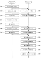
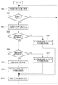
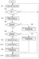
図3Aおよび図3Bに示されるように、本実施形態に係る制御方法は、内視鏡2の初期位置を設定する工程SB2と、被検体内の第1領域の第1位置情報および第1回転角情報を決定する工程SB3,SB4と、被検体内の第2領域の第2位置情報および第2回転角情報を決定する工程SB5,SB6と、被検体内の第3領域の第3位置情報および第3回転角情報を算出する工程SB7,SB8と、位置情報および回転角情報を記憶部13に記憶させる工程SB9と、内視鏡2によって現在撮像されている現在の撮像領域に応じて内視鏡画像Eを回転させる工程SC4~SC9と、回転された内視鏡画像Eを表示装置5に出力する工程SC10と、を含む。
図3Aに示されるように、工程SB2~SB9はマニュアルモードにおいて実行され、図3Bに示されるように、工程SC3~SC10は自律モードにおいて実行される。
図3Aおよび図3Bに示されるように、本実施形態に係る制御方法は、内視鏡2の初期位置を設定する工程SB2と、被検体内の第1領域の第1位置情報および第1回転角情報を決定する工程SB3,SB4と、被検体内の第2領域の第2位置情報および第2回転角情報を決定する工程SB5,SB6と、被検体内の第3領域の第3位置情報および第3回転角情報を算出する工程SB7,SB8と、位置情報および回転角情報を記憶部13に記憶させる工程SB9と、内視鏡2によって現在撮像されている現在の撮像領域に応じて内視鏡画像Eを回転させる工程SC4~SC9と、回転された内視鏡画像Eを表示装置5に出力する工程SC10と、を含む。
図3Aに示されるように、工程SB2~SB9はマニュアルモードにおいて実行され、図3Bに示されるように、工程SC3~SC10は自律モードにおいて実行される。
術者等のユーザは、移動装置3に保持された内視鏡2を腹腔内に挿入した後、マニュアルモードに切り替え(SA1,SB1)、内視鏡2を腹腔内で移動させることによって見回しを開始する(SA3)。見回しは、腹腔内の全体を観察し、臓器および組織の位置等を確認する作業である。患者毎に臓器および組織の位置が異なるため、挿入毎にこの作業は必要となる。見回しにおいて、術者は、ピボット軸P1回りに内視鏡2を回転させることによって、解剖学的に特徴を有する少なくとも2つの特定組織を含む範囲を内視鏡2によって観察する。本実施形態において、特定組織は、大動脈Fおよび骨盤Gである。
図3Aに示されるように、見回しの前に、術者は、内視鏡2の初期位置を制御装置1に登録する(SA2)。例えば、術者は、内視鏡2を所望の初期位置に配置し、ユーザインタフェース16の所定のボタンを操作する。プロセッサ11は、所定のボタンが操作されたことに応答し、内視鏡2の現在の位置φを算出し、現在の位置φを初期位置φ=0°として記憶部13に記憶する(SB2)。位置φは、内視鏡2の、ピボット軸P1回りの周方向の位置であり、角度センサ3dによって検出される関節3b,3cの回転角度から算出される。位置φは、撮像領域の、ピボット軸P1回りの周方向の位置を表す。
次に、図4Aおよび図5Aに示されるように、術者は、大動脈Fを正面から撮像する位置(O点)に内視鏡2を配置し、大動脈Fが内視鏡画像E内の所望の回転角に配置されるように光軸C回りの内視鏡2の回転角ωを調整する(SA4)。ここでの大動脈Fの回転角は、内視鏡画像Eの中心点回りの周方向の位置である。本実施形態において、図5Aに示されるように、大動脈Fが内視鏡画像E内において水平に配置されるように回転角ωが調整される。次に、術者は、ユーザインタフェース16に第1指示を入力する(SA5)。
第1指示の入力後、術者は、O点において調整された回転角ωを維持しながら内視鏡2をO点からピボット軸P1回りに回転させることによって、大動脈Fの全体を内視鏡2によって観察する。図5Aおよび図5Bに示されるように、内視鏡2がO点からB点に向かって回転するにつれて、内視鏡画像E内で大動脈Fが回転移動する。B点は、内視鏡画像E内に大動脈Fが観察される範囲の端点である。
ユーザインタフェース16が第1指示を受け付けたことに応答し、プロセッサ11は、内視鏡画像Eに基づいて大動脈(第1特定組織)Fを含む第1領域の第1位置情報および第1回転角情報を決定する(SB3,SB4)。第1回転角情報は、第1領域の内視鏡画像Eの回転角を規定する情報である。
具体的には、記憶部13には、特定組織を含む画像と特定組織の種類との対応関係を機械学習した学習済みモデル1bが記憶されている。工程SB3において、プロセッサ11は、学習済みモデル1bを使用して内視鏡画像E内の大動脈Fを認識し、大動脈Fが内視鏡画像E内に含まれる内視鏡2の位置φの範囲を第1位置情報として決定する。すなわち、第1領域は、O点とB点との間の領域である。
例えば、第1位置情報はφ=0°~20°である。このように、工程SA2,SB2による初期位置の設定に代えて、プロセッサ11は、第1指示が受け付けられた時点での内視鏡2の位置φを、初期位置φ=0°に設定してもよい。すなわち、ユーザの所望のタイミングおよび場所で初期位置が決定される。
また、プロセッサ11は、学習済みモデル1bによる処理を経ずに、第1指示が受け付けられた時点での内視鏡2の位置φを、第1位置情報として設定してもよい。すなわち、ユーザの所望のタイミングおよび場所で第1位置情報が決定される。
例えば、第1位置情報はφ=0°~20°である。このように、工程SA2,SB2による初期位置の設定に代えて、プロセッサ11は、第1指示が受け付けられた時点での内視鏡2の位置φを、初期位置φ=0°に設定してもよい。すなわち、ユーザの所望のタイミングおよび場所で初期位置が決定される。
また、プロセッサ11は、学習済みモデル1bによる処理を経ずに、第1指示が受け付けられた時点での内視鏡2の位置φを、第1位置情報として設定してもよい。すなわち、ユーザの所望のタイミングおよび場所で第1位置情報が決定される。
次に、工程SB4において、プロセッサ11は、ユーザインタフェース16が第1指示を受け付けた時点での内視鏡画像Eおよび内視鏡2の回転角ωを、第1基準内視鏡画像および第1基準回転角にそれぞれ設定し、第1基準内視鏡画像および第1基準回転角に基づいて第1回転角情報を決定する。
具体的には、プロセッサ11は、所定の初期回転角ω=0°に対する第1基準回転角を、第1指示を受け付けた時点の位置φでの内視鏡画像Eの目標回転角θtとして算出する。算出された目標回転角θtは、第1指示を受け付けた時点の位置φにおいて、大動脈Fを内視鏡画像E内において水平に配置するのに必要な内視鏡画像Eの回転量を表す。本実施形態において、第1基準回転角ωを初期回転角0°に設定している。
具体的には、プロセッサ11は、所定の初期回転角ω=0°に対する第1基準回転角を、第1指示を受け付けた時点の位置φでの内視鏡画像Eの目標回転角θtとして算出する。算出された目標回転角θtは、第1指示を受け付けた時点の位置φにおいて、大動脈Fを内視鏡画像E内において水平に配置するのに必要な内視鏡画像Eの回転量を表す。本実施形態において、第1基準回転角ωを初期回転角0°に設定している。
次に、プロセッサ11は、第1位置情報に含まれる他の位置φにおいて取得された内視鏡画像Eについて、内視鏡画像E内の大動脈Fを第1基準内視鏡画像内の大動脈Fに一致させるために必要な内視鏡画像Eの回転量Δθを算出する。次に、プロセッサ11は、回転量Δθを第1基準回転角に加算することによって、他の位置φでの目標回転角θtを算出する。算出された目標回転角θtは、他の位置φにおいて、大動脈Fを内視鏡画像E内において水平に配置するのに必要な内視鏡画像Eの回転量を表す。図5Cは、B点での目標角度θtだけ回転された図5Bの内視鏡画像Eを示す。
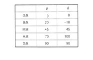
以上のようにして、プロセッサ11は、第1位置情報に含まれる各位置φ=0°,…,20°において大動脈Fを水平に配置するための内視鏡画像Eの目標回転角θtを算出し、各位置φ=0°,…,20°での目標回転角θtを第1回転角情報として決定する。図7には、第1回転角情報として、φ=0°,20°における目標回転角θt=0°,-10°のみが代表して記載されている。
次に、図4Bに示されるように、術者は、骨盤Gを撮像する位置(D点)に内視鏡2を配置する。初期回転角ω=0°で骨盤Gを観察した場合、図6Aに示されるように、骨盤Gが内視鏡画像E内において不適切な位置に配置され得る。術者は、骨盤Gが内視鏡画像E内の所望の回転角に配置されるように内視鏡2の光軸C回りの回転角ωを調整し(SA6)、ユーザインタフェース16に第2指示を入力する(SA7)。本実施形態において、図6Bに示されるように、骨盤Gが内視鏡画像E内において上方に配置されるように回転角ωが調整される。
第2指示の入力後、術者は、D点において調整された回転角ωを維持しながら内視鏡2をD点からピボット軸P1回りに回転させることによって、骨盤Gの全体を内視鏡2によって観察する。このときも、内視鏡2がD点からA点に向かって回転するにつれて、内視鏡画像E内で骨盤Gが回転移動する。A点は、内視鏡画像E内に骨盤Gが観察される範囲の端点である。
ユーザインタフェース16が第2指示を受け付けたことに応答し、プロセッサ11は、内視鏡画像Eに基づいて骨盤(第2特定組織)Gを含む第2領域の第2位置情報および第2回転角情報を決定する(SB5,SB6)。第2回転角情報は、第2領域の内視鏡画像Eの回転角を規定する情報である。
具体的には、工程SB5において、プロセッサ11は、学習済みモデル1bを使用して内視鏡画像E内の骨盤Gを認識し、骨盤Gが内視鏡画像E内に含まれる内視鏡2の位置φの範囲を第2位置情報として決定する。すなわち、第2領域は、D点とA点との間の領域である。例えば、第2位置情報はφ=70°~90°である。
なお、第2位置情報に関しても、プロセッサ11は、学習済みモデル1bによる処理を経ずに、第2指示が受け付けられた時点での内視鏡2の位置φを、第2位置情報として設定してもよい。すなわち、ユーザの所望のタイミングおよび場所で第2位置情報が決定される。
なお、第2位置情報に関しても、プロセッサ11は、学習済みモデル1bによる処理を経ずに、第2指示が受け付けられた時点での内視鏡2の位置φを、第2位置情報として設定してもよい。すなわち、ユーザの所望のタイミングおよび場所で第2位置情報が決定される。
次に、工程SB6において、プロセッサ11は、ユーザインタフェース16が第2指示を受け付けた時点での内視鏡画像Eおよび内視鏡2の回転角ωを、第2基準内視鏡画像および第2基準回転角にそれぞれ設定し、第2基準内視鏡画像および第2基準回転角に基づいて第2回転角情報を決定する。
具体的には、プロセッサ11は、初期回転角ω=0°に対する第2基準回転角を、第2指示を受け付けた時点の位置φでの内視鏡画像Eの目標回転角θtとして算出する。算出された目標回転角θtは、第2指示を受け付けた時点の位置φにおいて、骨盤Gを内視鏡画像E内において上方に配置するのに必要な内視鏡画像Eの回転量を表す。
具体的には、プロセッサ11は、初期回転角ω=0°に対する第2基準回転角を、第2指示を受け付けた時点の位置φでの内視鏡画像Eの目標回転角θtとして算出する。算出された目標回転角θtは、第2指示を受け付けた時点の位置φにおいて、骨盤Gを内視鏡画像E内において上方に配置するのに必要な内視鏡画像Eの回転量を表す。
次に、プロセッサ11は、第2位置情報に含まれる他の位置φにおいて取得された内視鏡画像Eについて、内視鏡画像E内の骨盤Gを第2基準内視鏡画像内の骨盤Gに一致させるために必要な内視鏡画像Eの回転量Δθを算出する。次に、プロセッサ11は、回転量Δθを第2基準回転角に加算することによって、他の位置φでの目標回転角θtを算出する。算出された目標回転角θtは、他の位置φにおいて、骨盤Gを内視鏡画像E内において上方に配置するのに必要な内視鏡画像Eの回転量を表す。
以上のようにして、プロセッサ11は、第2位置情報に含まれる各位置φ=70°,…,90°において骨盤Gを上方に配置するための内視鏡画像Eの目標回転角θtを算出し、各位置φ=70°,…,90°での目標回転角θtを第2回転角情報として決定する。図7には、第2回転角情報として、φ=70°,90°における目標回転角θt=100°,90°のみが代表して記載されている。
次に、プロセッサ11は、第3領域の第3位置情報および第3回転角情報を、第1位置情報、第1回転角情報、第2位置情報および第2回転角情報に基づいて算出する(SB7,SB8)。第3領域は、第1領域および第2領域とは異なる領域であり、本実施形態において、A点とB点との間の領域である。
工程SB7において、プロセッサ11は、第1位置情報と第2位置情報との間の位置φの範囲を第3位置情報として決定する。例えば、第3位置情報はφ=20°~70°である。
工程SB7において、プロセッサ11は、第1位置情報と第2位置情報との間の位置φの範囲を第3位置情報として決定する。例えば、第3位置情報はφ=20°~70°である。
次に、工程SB8において、プロセッサ11は、第1、第2、第3位置情報および第1、第2回転角情報に基づいて第3回転角情報を算出する。第3回転角情報は、第3領域の内視鏡画像Eの回転角を規定する情報である。
具体的には、プロセッサ11は、第3位置情報と第1および第2位置情報との間の位置関係を算出し、位置関係、第1回転角情報および第2回転角情報に基づいて第3回転角情報を算出する。
具体的には、プロセッサ11は、第3位置情報と第1および第2位置情報との間の位置関係を算出し、位置関係、第1回転角情報および第2回転角情報に基づいて第3回転角情報を算出する。
一例として、第3位置情報の各位置φ(M点)がA点とB点との間の軌跡をm:nに内分する内分点であると考える。プロセッサ11は、比m:n、A点の回転角100°およびB点の回転角-10°に基づいて、各位置φでの目標回転角θtを算出する。例えば、位置φ=45°は、A点とB点との間の軌跡を1:1に内分するので、位置φ=45°での目標回転角θtは、-10°と100°との間の中央値である45°である。
これにより、位置φがB点からA点に向かって変化するにつれて、100°から-10°に向かって漸次変化する目標回転角θtが算出される。
プロセッサ11は、各位置φ=20°,…,70°での目標回転角θtを第3回転角情報として決定する。図7には、第3回転角情報として、φ=45°における目標回転角θt=45°のみが代表して記載されている。
プロセッサ11は、各位置φ=20°,…,70°での目標回転角θtを第3回転角情報として決定する。図7には、第3回転角情報として、φ=45°における目標回転角θt=45°のみが代表して記載されている。
すなわち、第3領域は、第1領域および第2領域における骨盤Gや大動脈Fのように、内視鏡画像Eの回転角の指標となる特定組織が内視鏡画像内に映らない領域である。このような領域では、学習済みモデル1bによる特定組織の認識およびユーザによる所望の回転角の決定が困難である。そのため、第1領域および第2領域の第1および第2位置情報ならびに第1および第2回転角情報に基づいた第3位置情報および第3回転角情報の算出が必要となる。
次に、工程SB9において、プロセッサ11は、工程SB3~SB8において決定された第1位置情報、第1回転角情報、第2位置情報、第2回転角情報、第3位置情報および第3回転角情報を、記憶部13に記憶させる。これにより、図7に示されるように、撮像領域の位置を表す内視鏡2の回転角度φと、各回転角度φにおける内視鏡画像Eの目標回転角θtとを含むデータが記憶部13に生成される。
見回しが終了した後、術者は、マニュアルモードから自律モードへ切り替え、大動脈Fおよび骨盤Gを処置具6によって処置する。図3Bに示されるように、術者によって自律モードに切り替えられると(SC2)、プロセッサ11は、回転関節3cを回転させることによって内視鏡2の回転角ωを初期回転角0°に一致させ、回転角ωを0°に維持しながら、移動装置3を制御することによって処置具6の先端に内視鏡2を追従させる(SC3)。また、プロセッサ11は、内視鏡2の追従と並行して、表示画面5aに表示される内視鏡画像Eの上下方向を制御する(SC4~SC10)。
プロセッサ11は、装置1,3の起動中、関節3b,3cの回転角度を移動装置3から逐次受信し、関節3b,3cの回転角度から内視鏡2の現在位置φを算出する(SC1)。
プロセッサ11は、内視鏡2の現在位置、第1位置情報および第2位置情報に基づいて、現在の撮像領域が第1領域、第2領域および第3領域のいずれに含まれるかを判定する(SC4,SC6,SC8)。
プロセッサ11は、内視鏡2の現在位置、第1位置情報および第2位置情報に基づいて、現在の撮像領域が第1領域、第2領域および第3領域のいずれに含まれるかを判定する(SC4,SC6,SC8)。
具体的には、現在位置φが第1位置情報(φ=0°~20°)に含まれる場合、プロセッサ11は、現在の撮像領域が第1領域に含まれると判定する(SC4のYES)。次に、プロセッサ11は、記憶部13に記憶されている第1回転角情報に基づいて、内視鏡画像Eを該内視鏡画像Eの平面内において回転させる(SC5)。具体的には、プロセッサ11は、現在位置φの目標回転角θtを記憶部13から読み出し、目標回転角θtだけ内視鏡画像Eを画像処理によって回転させる。次に、プロセッサ11は、回転された内視鏡画像Eを制御装置1から表示装置5に出力し表示画面5aに表示させる(SC10)。
回転された内視鏡画像Eにおいて、大動脈Fは水平に配置される。したがって、内視鏡2がφ=0°~20°の範囲内を移動し大動脈Fを含む内視鏡画像Eを取得している間、表示画面5aに表示される内視鏡画像E内の大動脈Fは水平に維持される。例えば、O点からB点まで内視鏡2がピボット軸P1回りに20°揺動した場合、内視鏡画像Eは0°から-10°まで回転する。
現在位置φが第2位置情報(φ=70°~90°)に含まれる場合、プロセッサ11は、現在の撮像領域が第2領域に含まれると判定する(SC4のNOかつSC6のYES)。次に、プロセッサ11は、記憶部13に記憶されている第2回転角情報に基づいて、内視鏡画像Eを該内視鏡画像Eの平面内において回転させる(SC7)。具体的には、プロセッサ11は、現在位置φの目標回転角θtを記憶部13から読み出し、目標回転角θtだけ画像処理によって内視鏡画像Eを回転させる。次に、プロセッサ11は、回転された内視鏡画像Eを制御装置1から表示装置5に出力し表示画面5aに表示させる(SC10)。
回転された内視鏡画像Eにおいて、骨盤Gは上方に配置される。したがって、内視鏡2がφ=70°~90°の範囲内を移動し骨盤Gを含む内視鏡画像Eを取得している間、表示画面5aに表示される内視鏡画像E内の骨盤Gは上方に維持される。例えば、A点からD点まで内視鏡2がピボット軸P1回りに20°揺動した場合、内視鏡画像Eは100°から90°まで回転する。
現在位置φが第1位置情報および第2位置情報のいずれにも含まれない場合(SC4のNOかつSC6のNO)、プロセッサ11は、現在の撮像領域が第3領域に含まれると判定する(SC8)。次に、プロセッサ11は、記憶部13に記憶されている第3回転角情報に基づいて、内視鏡画像Eを該内視鏡画像Eの平面内において回転させる(SC9)。具体的には、プロセッサ11は、現在位置φの回転角を記憶部13から読み出し、回転角だけ内視鏡画像Eを画像処理によって回転させる。次に、プロセッサ11は、回転された内視鏡画像Eを制御装置1から表示装置5に出力し表示画面5aに表示させる(SC10)。
表示画面5aに表示される内視鏡画像Eは、位置φに応じた目標回転角θtだけ回転されており、位置φが第1領域側から第2領域側へ変化するにつれて、目標回転角θtが第1領域の目標回転角から第2領域の目標回転角へ向かって次第に変化する。したがって、例えば、内視鏡2がB点からA点までピボット軸P1回りに揺動した場合、表示画面5aに表示される内視鏡画像Eは-10°から100°まで一方向に回転する。
以上説明したように、本実施形態によれば、特定組織Fを含む第1領域の第1位置情報と、特定組織Fを術者が所望する回転角に配置するための内視鏡画像Eの目標回転角θtを規定する第1回転角情報とが、記憶部13に記憶される。また、特定組織Gを含む第2領域の第2位置情報と、特定組織Gを術者が所望する回転角に配置するための内視鏡画像Eの目標回転角θtを規定する第2回転角情報とが、記憶部13に記憶される。さらに、第1領域と第2領域との間の第3領域の第3回転角情報として、第1回転角情報の目標回転角θtと第2回転角情報の目標回転角θtとの間で漸次変化する目標回転角θtが補間され、記憶部13に記憶される。
その後、自律モードにおいて、現在の撮像領域の位置φに応じた目標回転角θtだけ内視鏡画像Eが回転されることによって、内視鏡画像Eの上下方向が自動的に調整される。具体的には、現在の撮像領域が特定組織F,Gを含む第1または第2領域であるときには、特定組織F,Gが所定の回転角で配置される目標回転角θtだけ内視鏡画像Eが自動的に回転させられる。現在の撮像領域が特定組織F,Gを含まない第3領域であるときには、第1および第2回転角情報から推定される適切な目標回転角θtだけ内視鏡画像Eが自動的に回転させられる。
このように、腹腔内の現在の撮像領域の位置に応じた適切な上下方向の内視鏡画像Eを操作者に提供することができる。
また、内視鏡画像Eの上下方向が自動的に調整されることによって、術者のストレスを軽減することができるとともに、処置時間を短縮することができる。すなわち、内視鏡画像Eの上下方向を術者が自身で調整する場合、術者は、操作中の処置具6から手を一旦放し、内視鏡2を手動で回転させなければならない。本実施形態によれば、上下方向の調整のために術者が内視鏡2を操作する必要が無いので、術者は、処置を中断することなく継続することができる。
また、内視鏡画像Eの上下方向が自動的に調整されることによって、術者のストレスを軽減することができるとともに、処置時間を短縮することができる。すなわち、内視鏡画像Eの上下方向を術者が自身で調整する場合、術者は、操作中の処置具6から手を一旦放し、内視鏡2を手動で回転させなければならない。本実施形態によれば、上下方向の調整のために術者が内視鏡2を操作する必要が無いので、術者は、処置を中断することなく継続することができる。
(第2実施形態)
次に、本発明の第2実施形態に係る内視鏡システム、制御装置、制御方法および記録媒体について図面を参照して説明する。
本実施形態は、プロセッサ11が、画像処理に代えて内視鏡2の回転によって内視鏡画像Eを回転させる点において、第1実施形態と相違する。本実施形態においては、第1実施形態と相違する構成について説明し、第1実施形態と共通の構成については同一の符号を付して説明を省略する。
次に、本発明の第2実施形態に係る内視鏡システム、制御装置、制御方法および記録媒体について図面を参照して説明する。
本実施形態は、プロセッサ11が、画像処理に代えて内視鏡2の回転によって内視鏡画像Eを回転させる点において、第1実施形態と相違する。本実施形態においては、第1実施形態と相違する構成について説明し、第1実施形態と共通の構成については同一の符号を付して説明を省略する。
本実施形態に係る内視鏡システム10は、第1実施形態と同様、制御装置1、内視鏡2、移動装置3、内視鏡プロセッサ4および表示装置5を備える。
図8Aおよび図8Bは、本実施形態においてプロセッサ11が実行する制御方法を示している。
図8Aおよび図8Bは、本実施形態においてプロセッサ11が実行する制御方法を示している。
図8Aおよび図8Bに示されるように、本実施形態に係る制御方法は、内視鏡2の初期位置を決定する工程SB2と、被検体内の第1領域の第1位置情報および第1回転角情報を決定する工程SB3,SB4’と、被検体内の第2領域の第2位置情報および第2回転角情報を決定する工程SB5,SB6’と、被検体内の第3領域の第3位置情報および第3回転角情報を算出する工程SB7,SB8’と、位置情報および回転角情報を記憶部13に記憶させる工程SB9と、内視鏡2によって現在撮像されている現在の撮像領域に応じて内視鏡画像Eを回転させる工程SC4~SC9’と、回転した内視鏡画像Eを表示装置5に出力する工程SC10と、を含む。
図8Aに示されるように、工程SB2~SB9はマニュアルモードにおいて実行され、図8Bに示されるように、工程SC4~SC10は自律モードにおいて実行される。
図8Aに示されるように、工程SB2~SB9はマニュアルモードにおいて実行され、図8Bに示されるように、工程SC4~SC10は自律モードにおいて実行される。
第1実施形態と同様、ユーザは、工程SA1~SA5を行う。ユーザインタフェース16が第1指示を受け付けたことに応答し、プロセッサ11は、内視鏡画像Eに基づいて第1領域の第1位置情報および第1回転角情報を決定する(SB3,SB4’)。
具体的には、工程SB3の次の工程SB4’において、プロセッサ11は、ユーザインタフェース16が第1指示を受け付けた時点での内視鏡画像Eおよび内視鏡2の回転角ωを、第1基準内視鏡画像および第1基準回転角にそれぞれ設定する。
具体的には、工程SB3の次の工程SB4’において、プロセッサ11は、ユーザインタフェース16が第1指示を受け付けた時点での内視鏡画像Eおよび内視鏡2の回転角ωを、第1基準内視鏡画像および第1基準回転角にそれぞれ設定する。
次に、プロセッサ11は、所定の初期回転角ω=0°に対する第1基準回転角を、第1指示を受け付けた時点の位置φでの内視鏡2の目標回転角ωtとして算出する。
次に、プロセッサ11は、第1位置情報に含まれる他の位置φにおいて取得された内視鏡画像Eについて、内視鏡画像E内の大動脈Fを第1基準内視鏡画像内の大動脈Fに一致させるために必要な内視鏡画像Eの回転量Δθを算出する。次に、プロセッサ11は、回転量Δθを第1基準回転角に加算することによって、他の位置φでの内視鏡2の目標回転角ωtを算出する。
以上のようにして、プロセッサ11は、第1位置情報に含まれる各位置φ=0°,…,20°において大動脈Fを水平に配置するための内視鏡2の目標回転角ωtを算出し、各位置φ=0°,…,20°での目標回転角ωtを第1回転角情報として決定する。
次に、プロセッサ11は、第1位置情報に含まれる他の位置φにおいて取得された内視鏡画像Eについて、内視鏡画像E内の大動脈Fを第1基準内視鏡画像内の大動脈Fに一致させるために必要な内視鏡画像Eの回転量Δθを算出する。次に、プロセッサ11は、回転量Δθを第1基準回転角に加算することによって、他の位置φでの内視鏡2の目標回転角ωtを算出する。
以上のようにして、プロセッサ11は、第1位置情報に含まれる各位置φ=0°,…,20°において大動脈Fを水平に配置するための内視鏡2の目標回転角ωtを算出し、各位置φ=0°,…,20°での目標回転角ωtを第1回転角情報として決定する。
次に、ユーザは、工程SA6,SA7を行う。ユーザインタフェース16が第2指示を受け付けたことに応答し、プロセッサ11は、内視鏡画像Eに基づいて第2領域の第2位置情報および第2回転角情報を決定する(SB5,SB6’)。
具体的には、工程SB5の次の工程SB6’において、プロセッサ11は、ユーザインタフェース16が第2指示を受け付けた時点での内視鏡画像Eおよび内視鏡2の回転角ωを、第2基準内視鏡画像および第2基準回転角にそれぞれ設定する。
具体的には、工程SB5の次の工程SB6’において、プロセッサ11は、ユーザインタフェース16が第2指示を受け付けた時点での内視鏡画像Eおよび内視鏡2の回転角ωを、第2基準内視鏡画像および第2基準回転角にそれぞれ設定する。
次に、プロセッサ11は、初期回転角ω=0°に対する第2基準回転角を、第2指示を受け付けた時点の位置φでの内視鏡2の目標回転角ωtとして算出する。
次に、プロセッサ11は、第2位置情報に含まれる他の位置φにおいて取得された内視鏡画像Eについて、内視鏡画像E内の骨盤Gを第2基準内視鏡画像内の大動脈Gに一致させるために必要な内視鏡画像Eの回転量Δθを算出する。次に、プロセッサ11は、回転量Δθを第2基準回転角に加算することによって、他の位置φでの内視鏡2の目標回転角ωtを算出する。
以上のようにして、プロセッサ11は、第2位置情報に含まれる各位置φ=70°,…,90°において骨盤Gを上方に配置するための内視鏡2の目標回転角ωtを算出し、各位置φ=70°,…,90°での目標回転角ωtを第2回転角情報として決定する。
次に、プロセッサ11は、第2位置情報に含まれる他の位置φにおいて取得された内視鏡画像Eについて、内視鏡画像E内の骨盤Gを第2基準内視鏡画像内の大動脈Gに一致させるために必要な内視鏡画像Eの回転量Δθを算出する。次に、プロセッサ11は、回転量Δθを第2基準回転角に加算することによって、他の位置φでの内視鏡2の目標回転角ωtを算出する。
以上のようにして、プロセッサ11は、第2位置情報に含まれる各位置φ=70°,…,90°において骨盤Gを上方に配置するための内視鏡2の目標回転角ωtを算出し、各位置φ=70°,…,90°での目標回転角ωtを第2回転角情報として決定する。
次に、プロセッサ11は、第3領域の第3位置情報および第3回転角情報を、第1位置情報、第1回転角情報、第2位置情報および第2回転角情報に基づいて算出する(SB7,SB8’)。具体的には、工程SB7の次の工程SB8’において、プロセッサ11は、工程SB8’と同様にして、第3位置情報の各位置φ=20°,…,70°での目標回転角ωtを第3回転角情報として決定する。
次に、工程SB9において、プロセッサ11は、工程SB3,SB4’,SB5,SB6’,SB7,SB8’において決定された位置情報および回転角情報を、記憶部13に記憶させる。これにより、撮像領域の位置を表す内視鏡2の回転角度φと、各回転角度φにおける内視鏡2の目標回転角ωtとを含むデータが記憶部13に生成される。
続いて、図8Bに示されるように、プロセッサ11は、内視鏡2の現在位置φを算出する(SC1)。自律モードに切り替えられると(SC2のYES)、プロセッサ11は、現在の撮像領域が第1領域、第2領域および第3領域のいずれに含まれるかを判定する(SC4,SC6,SC8)。
現在の撮像領域が第1領域に含まれると判定した場合(SC4のYES)、プロセッサ11は、記憶部13に記憶されている第1回転角情報に基づいて内視鏡2を回転させる(SC5’)。具体的には、プロセッサ11は、現在位置φの目標回転角ωtを記憶部13から読み出し、目標回転角ωtに内視鏡2を回転させることによって内視鏡画像Eを回転させる。
現在の撮像領域が第2領域に含まれると判定した場合(SC4のNOかつSC6のYES)、プロセッサ11は、記憶部13に記憶されている第2回転角情報に基づいて内視鏡2を回転させる(SC7’)。具体的には、プロセッサ11は、現在位置φの目標回転角ωtを記憶部13から読み出し、目標回転角ωtだけ内視鏡2を回転させることによって内視鏡画像Eを回転させる。
現在の撮像領域が第3領域に含まれると判定した場合(SC7)、プロセッサ11は、記憶部13に記憶されている第3回転角情報に基づいて内視鏡2を回転させる(SC8’)。具体的には、プロセッサ11は、現在位置φの目標回転角ωtを記憶部13から読み出し、目標回転角ωtだけ内視鏡2を回転させることによって内視鏡画像Eを回転させる。
工程SC5’、SC7’またはSC9’の次に、プロセッサ11は、回転された内視鏡画像Eを制御装置1から表示装置5に出力し表示画面5aに表示させる(SC10)。
工程SC5’、SC7’またはSC9’の次に、プロセッサ11は、回転された内視鏡画像Eを制御装置1から表示装置5に出力し表示画面5aに表示させる(SC10)。
以上説明したように、本実施形態によれば、第1実施形態と同様、自律モードにおいて、現在の撮像領域の位置φに応じた目標回転角ωtに内視鏡2が回転されることによって、内視鏡画像Eの上下方向が自動的に調整される。具体的には、現在の撮像領域が特定組織F,Gを含む第1または第2領域であるときには、特定組織F,Gが所定の回転角で配置される目標回転角ωtに内視鏡2が自動的に回転させられる。現在の撮像領域が特定組織F,Gを含まない第3領域であるときには、第1および第2回転角情報から推定される適切な目標回転角ωtに内視鏡2が自動的に回転させられる。
このように、腹腔内の現在の撮像領域の位置に応じた適切な上下方向の内視鏡画像Eを操作者に提供することができる。また、内視鏡画像Eの上下方向が自動的に調整されることによって、術者のストレスを軽減することができるとともに、処置時間を短縮することができる。
このように、腹腔内の現在の撮像領域の位置に応じた適切な上下方向の内視鏡画像Eを操作者に提供することができる。また、内視鏡画像Eの上下方向が自動的に調整されることによって、術者のストレスを軽減することができるとともに、処置時間を短縮することができる。
また、本実施形態によれば、光軸C回りの内視鏡2の回転によって内視鏡画像Eを回転させることによって、内視鏡画像Eを回転させるための画像処理を無くすことができ、プロセッサ11の負荷を減らすことができる。また、ユーザは、内視鏡2の体外に配置される部分の回転角ωを目視で確認することによって、内視鏡画像Eの上下方向を感覚的に認識することができる。
本実施形態において、光軸C回りの内視鏡2全体の回転によって内視鏡画像Eを回転させることとしたが、これに代えて、光軸C回りの内視鏡2の回転角ωを維持しながら撮像素子2aを光軸C回りに回転させてもよい。この場合、撮像素子2aを回転させるための回転機構が内視鏡2に設けられる。
内視鏡2の本体に対する撮像素子2aの回転によっても、内視鏡2全体を回転させたときと同様に内視鏡画像Eを回転させることができる。
内視鏡2の本体に対する撮像素子2aの回転によっても、内視鏡2全体を回転させたときと同様に内視鏡画像Eを回転させることができる。
(第3実施形態)
次に、本発明の第3実施形態に係る内視鏡システム、制御装置、制御方法および記録媒体について図面を参照して説明する。
本実施形態は、光軸C回りの内視鏡2の回転および画像処理の組み合わせによって内視鏡画像Eを回転させる点において、第1および第2実施形態と相違する。本実施形態においては、第1および第2実施形態と相違する構成について説明し、第1および第2実施形態と共通の構成については同一の符号を付して説明を省略する。
次に、本発明の第3実施形態に係る内視鏡システム、制御装置、制御方法および記録媒体について図面を参照して説明する。
本実施形態は、光軸C回りの内視鏡2の回転および画像処理の組み合わせによって内視鏡画像Eを回転させる点において、第1および第2実施形態と相違する。本実施形態においては、第1および第2実施形態と相違する構成について説明し、第1および第2実施形態と共通の構成については同一の符号を付して説明を省略する。
本実施形態に係る内視鏡システム10は、第1実施形態と同様、制御装置1、内視鏡2、移動装置3、内視鏡プロセッサ4および表示装置5を備える。
図9は、本実施形態において、プロセッサ11が自律モードで実行する制御方法を示している。本実施形態に係る制御方法は、第2実施形態において説明した工程SB2,SB3,SB4’,SB5,SB6’,SB7,SB8’,SB9,SC1~SC4,SC5’,SC6,SC7’,SC8,SC9’に加えて、内視鏡2の回転角ωが所定の限界角であるか否かを判断する工程SC11と、内視鏡画像Eを画像処理によって回転させる工程SC12と、を含む。
図9は、本実施形態において、プロセッサ11が自律モードで実行する制御方法を示している。本実施形態に係る制御方法は、第2実施形態において説明した工程SB2,SB3,SB4’,SB5,SB6’,SB7,SB8’,SB9,SC1~SC4,SC5’,SC6,SC7’,SC8,SC9’に加えて、内視鏡2の回転角ωが所定の限界角であるか否かを判断する工程SC11と、内視鏡画像Eを画像処理によって回転させる工程SC12と、を含む。
工程SB9の後、図9に示されるように、プロセッサ11は、内視鏡2の現在位置φを算出する(SC1)。自律モードに切り替えられると(SC2のYES)、プロセッサ11は、工程SC1~SC4,SC5’,SC6,SC7’,SC8,SC9’を実行する。
工程SC5‘,SC7’,SC9’において、プロセッサ11は、角度センサ3dによって検出される回転関節3cの回転角度に基づいて、内視鏡2の回転角ωが内視鏡2の回転可能範囲の限界角に達しているか否かを判断する(SC11)。内視鏡2が回転することができる回転可能範囲は、物理的な制約等によって制限されることがある。例えば、内視鏡2および移動装置3の内部のケーブルには内視鏡2の回転によってねじれが発生するので、過度なねじれが生じないように内視鏡2の回転可能範囲が設定される。
回転角ωが限界角に達することなく内視鏡2が目標回転角ωtまで回転した場合(SC11のNO)、プロセッサ11は、回転した内視鏡画像Eを表示装置5に出力する(SC10)。
一方、回転角ωが目標回転角ωtに達する前に限界角に達した場合(SC11のYES)、プロセッサ11は、内視鏡2の回転を限界角において停止させ、次に、目標回転角ωtまで足りない回転角だけ内視鏡画像Eを画像処理によって回転させ(SC12)、回転された内視鏡画像Eを表示装置5に出力する(SC10)。
一方、回転角ωが目標回転角ωtに達する前に限界角に達した場合(SC11のYES)、プロセッサ11は、内視鏡2の回転を限界角において停止させ、次に、目標回転角ωtまで足りない回転角だけ内視鏡画像Eを画像処理によって回転させ(SC12)、回転された内視鏡画像Eを表示装置5に出力する(SC10)。
以上説明したように、本実施形態によれば、光軸C回りの内視鏡2の回転と画像処理とを組み合わせることによって、内視鏡2の回転のみでは達成することが難しい内視鏡画像Eの回転を実現することができる。
本実施形態のその他の効果は第1および第2実施形態と同一であるので、説明を省略する。
本実施形態のその他の効果は第1および第2実施形態と同一であるので、説明を省略する。
(第1変形例)
次に、第1から第3実施形態に係る内視鏡システム10、制御装置1、制御方法および記録媒体の第1変形例について説明する。
図10に示されるように、本変形例は、内視鏡2が斜視型である点において、上述した第1から第3実施形態と相違する。
次に、第1から第3実施形態に係る内視鏡システム10、制御装置1、制御方法および記録媒体の第1変形例について説明する。
図10に示されるように、本変形例は、内視鏡2が斜視型である点において、上述した第1から第3実施形態と相違する。
斜視型の内視鏡2は、長手軸Iを有し被検体内に挿入される長尺の挿入部2bと、撮像素子2aを含み挿入部2bの基端に接続された撮像部2cとを有する。回転関節3cの回転によって挿入部2bおよび撮像部2cは長手軸I回りに一体的に回転する。なお、分離型の斜視型鏡の場合、カメラヘッド(撮像部2c)および光学視管(挿入部2b)が別々の回転角情報を有するが、本変形例では、カメラヘッドおよび光学視管を一体的に回転させることによって共通の回転角情報として処理を行う。
直視型の内視鏡2の場合、視軸(光軸)Cが長手軸Iと同軸であるため、内視鏡2が長手軸I回りに回転しても視軸Cの位置は維持される。一方、斜視型の内視鏡2の場合、視軸Cが長手軸Iに対して傾斜するため、長手軸I回りの内視鏡2の回転に伴って視軸Cが長手軸I回りに回転移動し、撮像領域が移動する。
図11Aおよび図11Bは、本変形例においてプロセッサ11が実行する制御方法を示している。図11Aおよび図11Bに示されるように、本変形例に係る制御方法は、工程SB2’,SB3~SB9と、工程SC3’,SC4~SC10と、を含む。
工程SB2’において、プロセッサ11は、内視鏡2の現在位置φを初期位置φ=0°に設定し、内視鏡2の現在姿勢ωを初期姿勢ω=0°に設定する。内視鏡2の姿勢ωは、長手軸I回りの回転角であり、長手軸Iに対する視軸Cの姿勢に相当する。
工程SB2’において、プロセッサ11は、内視鏡2の現在位置φを初期位置φ=0°に設定し、内視鏡2の現在姿勢ωを初期姿勢ω=0°に設定する。内視鏡2の姿勢ωは、長手軸I回りの回転角であり、長手軸Iに対する視軸Cの姿勢に相当する。
次に、ユーザインタフェース16が第1指示を受け付けたことに応答し(SA5)、プロセッサ11は、第1位置情報および第1回転角情報を決定し(SB3,SB4)、さらに、第1指示を受け付けた時点での内視鏡2の第1姿勢の情報を保持する。
次に、ユーザインタフェース16が第2指示を受け付けたことに応答し(SA7)、プロセッサ11は、第2位置情報および第2回転角情報を決定し(SB5,SB6)、さらに、第2指示を受け付けた時点での内視鏡2の第2姿勢の情報を保持する。
次に、ユーザインタフェース16が第2指示を受け付けたことに応答し(SA7)、プロセッサ11は、第2位置情報および第2回転角情報を決定し(SB5,SB6)、さらに、第2指示を受け付けた時点での内視鏡2の第2姿勢の情報を保持する。
工程SB9において、プロセッサ11は、位置情報および回転角情報に加えて、第1姿勢および第2姿勢を記憶部13に記憶させる。これにより、撮像領域の位置を表す内視鏡2の回転角度φと、各回転角度φにおける内視鏡画像Eの目標回転角θtと、各撮像領域に対応する内視鏡2の第1姿勢および第2姿勢と、を含むデータが記憶部13に生成される。
続いて、自律モードにおいて、プロセッサ11は、移動装置3を制御することによって内視鏡2の位置および姿勢を制御し、処置具6の先端に内視鏡2を追従させる(SC3’)。ここで、プロセッサ11は、記憶部13に記憶された第1および第2位置情報と第1および第2姿勢とに基づいて内視鏡2の位置および姿勢を制御することによって、撮像領域が第1領域に含まれるときは内視鏡2の姿勢ωを第1姿勢に制御し、撮像領域が第2領域に含まれるときは内視鏡2の姿勢ωを第2姿勢に制御する。
そして、第1実施形態と同様、プロセッサ11は、現在の撮像領域に応じて内視鏡画像Eを画像処理によって目標回転角θtだけ回転させる(SC4~SC9)。
そして、第1実施形態と同様、プロセッサ11は、現在の撮像領域に応じて内視鏡画像Eを画像処理によって目標回転角θtだけ回転させる(SC4~SC9)。
前述したように、斜視型内視鏡2の場合、長手軸I回りの内視鏡2の回転によって撮像領域が移動する。そのため、内視鏡2の回転によって内視鏡画像Eを回転させる第2実施形態の制御方法のみでは、内視鏡画像Eの上下方向を制御することが難しい。
本変形例によれば、マニュアルモードにおいて、第1領域を撮像するときの内視鏡2の第1姿勢と、第2領域を撮像するときの内視鏡2の第2姿勢とが記憶される。そして、自律モードにおいて、第1領域の撮像時には、内視鏡2の姿勢が第1姿勢に制御されるとともに内視鏡画像Eの上下方向が画像処理による回転によって調整される。また、自律モードにおいて、第2領域の撮像時には、内視鏡2の姿勢が第2姿勢に制御されるとともに内視鏡画像Eの上下方向が画像処理による回転によって調整される。これにより、斜視型内視鏡2によって取得される内視鏡画像Eの上下方向を適切に制御することができる。
(第2変形例)
次に、第1から第3実施形態に係る内視鏡システム10、制御装置1、制御方法及び記録媒体13の第2変形例について説明する。
図12に示されるように、本変形例は、内視鏡2が湾曲部2dを有する点において、上述した第1から第3実施形態と相違する。
次に、第1から第3実施形態に係る内視鏡システム10、制御装置1、制御方法及び記録媒体13の第2変形例について説明する。
図12に示されるように、本変形例は、内視鏡2が湾曲部2dを有する点において、上述した第1から第3実施形態と相違する。
内視鏡2は、被検体内に挿入される長尺の挿入部2bと、挿入部2bの先端部に設けられ挿入部2bの長手軸Iに交差する方向に湾曲可能である湾曲部2dとを有する。湾曲部2dが湾曲している場合、視軸Cが長手軸Iに対して傾斜するため、長手軸I回りの内視鏡2の回転に伴って視軸Cが長手軸I回りに回転移動し、撮像領域が移動する。さらに、長手軸Iに対する視軸Cの傾斜方向および傾斜角度は、湾曲部2dの湾曲方向および湾曲角度に応じて異なる。
本変形例においてプロセッサ11が実行する制御方法は、第1変形例と同様、工程SB2’,SB3~SB9と、工程SC3’,SC4~SC10と、を含む。ただし、内視鏡2の姿勢として、長手軸I回りの回転角ωに代えて、湾曲部2dの回転方向および回転角度が用いられる。
すなわち、工程SB2’において、プロセッサ11は、湾曲部2dの現在の湾曲方向および湾曲角度を初期姿勢として設定する。そして、工程SB9において、プロセッサ11は、第1指示を受け付けた時点での湾曲部2dの湾曲方向および湾曲角度を第1姿勢として記憶部13に記憶させ、第2指示を受け付けた時点での湾曲部2dの湾曲方向および湾曲角度を第2姿勢として記憶部13に記憶させる。
また、自律モードの工程SC3’において、プロセッサ11は、記憶部13に記憶された第1および第2位置情報と第1および第2姿勢とに基づいて内視鏡2の位置および姿勢を制御することによって、撮像領域が第1領域に含まれるときは湾曲部2dの湾曲方向および湾曲角度を第1姿勢に制御し、撮像領域が第2領域に含まれるときは湾曲部2dの湾曲方向および湾曲角度を第2姿勢に制御する(SC3’)。
前述したように、湾曲部2dを有する内視鏡2の場合、湾曲部2dの湾曲方向および湾曲角度に応じて、撮像領域が内視鏡2の回転によって回転移動する。そのため、内視鏡2の回転によって内視鏡画像Eを回転させる第2実施形態の制御方法によって内視鏡画像Eの上下方向を制御することが難しい。
本変形例によれば、第1変形例と同様、自律モードにおいて、第1領域の撮像時には、内視鏡2の姿勢がマニュアルモードにおいて記憶された第1姿勢に制御されるとともに内視鏡画像Eの上下方向が画像処理による回転によって調整される。また、自律モードにおいて、第2領域の撮像時には、内視鏡2の姿勢がマニュアルモードにおいて記憶された第2姿勢に制御されるとともに内視鏡画像Eの上下方向が画像処理による回転によって調整される。これにより、湾曲部2dを有する内視鏡2によって取得される内視鏡画像Eの上下方向を適切に制御することができる。
上記各実施形態および各変形例において、プロセッサ11が、第3回転角情報をマニュアルモードにおいて計算し記憶部13に記憶させることとしたが、これに代えて、図13Aおよび図13Bに示されるように、自律モードの実行中に第3回転角情報をプロセッサ11がリアルタイムに計算してもよい(SC13)。言い換えれば、プロセッサ11は、マニュアルモードにおいて、第3位置情報および第3回転角情報の決定および記憶を行わない。この場合、第3領域とは、第1領域および第2領域ではない領域という意味になる。
各実施形態および各変形例の自律モードにおいて、現在の撮像領域が第3領域に含まれる(第1領域および第2領域のいずれでもない)と判定された場合、プロセッサ11は、内視鏡2の現在位置φにおける目標回転角θtまたはωtを、現在位置φ、第1位置情報、第1回転角情報、第2位置情報および第2回転角情報に基づいてリアルタイムに算出してもよい(SC13)。さらに、現在の撮像領域が第1領域および第2領域のいずれかに含まれる(第3領域に含まれない)場合、プロセッサ11は、目標回転角θtまたはωtをリアルタイムに算出せず、第1回転角情報または第2回転角情報に一致させればよい。このようにすることで、マニュアルモード時に記憶部13に記憶させる位置情報および回転角情報の量を減らすことができ、自律モードの操作時に必要となった第3位置情報および第3回転角情報のみを算出すれば良いので、システムへの負荷が軽減される。
また、プロセッサ11は、現在の撮像領域が第1領域または第2領域に含まれる場合は、事前に記憶されている第1位置情報または第2位置情報、または第1回転角情報または第2回転角情報を、現在の位置情報および回転角情報にアップデートしてもよい。アップデート後に内視鏡2を移動させ、現在の撮像領域が第1領域または第2領域に含まれていると判断された場合、アップデートした第1位置情報、第2位置情報、第1回転角情報、第2回転角情報を使用することができる。アップデートを行う場合、ユーザは、ユーザインタフェース16からアップデート指示を行えばよい。このようにすることで、気腹または体位の調整等に因り患者の体の一部が変形した場合でも、位置情報および回転角情報を現在の状況に応じた正しい情報に更新することが可能となる。
上記各実施形態および各変形例において、プロセッサ11が、内視鏡画像E内の特定組織を認識し、認識された特定組織に基づいて各位置情報および各回転角情報を決定することとしたが、これに代えて、各指示が受け付けられた時点での内視鏡2の位置φおよび回転角ωに基づいて各位置情報および各回転角情報を決定してもよい。
すなわち、マニュアルモードにおいて、術者は、所望の位置に所望の回転角ωで内視鏡2を配置し、第1指示を入力する。プロセッサ11は、ユーザインタフェース16が第1指示を受け付けた時点での内視鏡2の位置φの周辺範囲を第1位置情報に決定し、ユーザインタフェース16が第2指示を受け付けた時点での内視鏡2の回転角ωを第1回転角情報に決定する。
すなわち、マニュアルモードにおいて、術者は、所望の位置に所望の回転角ωで内視鏡2を配置し、第1指示を入力する。プロセッサ11は、ユーザインタフェース16が第1指示を受け付けた時点での内視鏡2の位置φの周辺範囲を第1位置情報に決定し、ユーザインタフェース16が第2指示を受け付けた時点での内視鏡2の回転角ωを第1回転角情報に決定する。
同様に、術者は、他の所望の位置に所望の回転角ωで内視鏡2を配置し、第2指示を入力する。プロセッサ11は、ユーザインタフェース16が第2指示を受け付けた時点での内視鏡2の位置φの周辺範囲を第2位置情報に決定し、ユーザインタフェース16が第2指示を受け付けた時点での内視鏡2の回転角ωを第2回転角情報に決定する。
この構成によれば、術者が、被検体内の任意の領域を第1領域および第2領域として登録することができ、より術者の感覚に沿った位置情報および回転角情報の決定が可能になる。また、第1および第2領域に特定組織が含まれない場合においても、学習済みモデル1bの処理を行わずに、第1および第2領域の位置情報および回転角情報を任意に決定し記憶することができる。
この構成によれば、術者が、被検体内の任意の領域を第1領域および第2領域として登録することができ、より術者の感覚に沿った位置情報および回転角情報の決定が可能になる。また、第1および第2領域に特定組織が含まれない場合においても、学習済みモデル1bの処理を行わずに、第1および第2領域の位置情報および回転角情報を任意に決定し記憶することができる。
内視鏡画像E内の特定組織に基づく位置情報および回転角情報の決定と、指示が受け付けられた時点での内視鏡2の位置φおよび回転角ωに基づく位置情報および回転角情報の決定と、が併用されてもよい。
例えば、プロセッサ11は、第1から第3実施形態およびこれらの変形例において説明したように内視鏡画像E内の特定組織F,Gに基づいて第1および第2位置情報と第1および第2回転角情報とを決定した後、術者の指示に基づいて、第1および第2領域とは異なる任意の領域の位置情報および回転角情報をさらに決定してもよい。
例えば、プロセッサ11は、第1から第3実施形態およびこれらの変形例において説明したように内視鏡画像E内の特定組織F,Gに基づいて第1および第2位置情報と第1および第2回転角情報とを決定した後、術者の指示に基づいて、第1および第2領域とは異なる任意の領域の位置情報および回転角情報をさらに決定してもよい。
上記各実施形態および各変形例において、特定組織が大動脈Fおよび骨盤Gであることとしたが、特定組織は、解剖学的に特徴を有する任意の臓器または組織であればよく、例えば子宮であってもよい。
上記各実施形態および各変形例において、2つの領域の位置情報および回転角情報を記憶することとしたが、これに代えて、3以上の領域の位置情報および回転角情報を記憶してもよい。これにより、事前に記憶された情報に基づいて位置情報および回転角情報を算出する場合の精度を向上させることが出来る。
上記各実施形態および各変形例において、2つの領域の位置情報および回転角情報を記憶することとしたが、これに代えて、3以上の領域の位置情報および回転角情報を記憶してもよい。これにより、事前に記憶された情報に基づいて位置情報および回転角情報を算出する場合の精度を向上させることが出来る。
上記各実施形態および各変形例において、撮像領域の位置を表す内視鏡2の位置φが、ピボット点Hを原点とする2次元極座標系で表現されることとしたが、これに代えて、3次元極座標系で表現されてもよい。すなわち、内視鏡2が、ピボット点Hを通り第1ピボット軸P1と直交する第2ピボット軸P2回りに揺動可能に支持され、撮像領域の位置が(φ1,φ2)として表現されてもよい。φ1は第1ピボット軸P1回りの回転角度であり、φ2は第2ピボット軸P2回りの回転角度である。この場合、第1位置情報、第2位置情報および第3位置情報の各々は、回転角度φ1,φ2を含む3次元情報である。
上記各実施形態および各変形例において、撮像領域の位置が、極座標系に代えて、他の種類の座標系で表されてもよい。例えば、撮像領域の位置が、穴Hを原点するデカルト座標系で表現されてもよい。
上記各実施形態および各変形例において、撮像領域の位置φの座標系が、被検体に対して固定されたグローバル座標系であることとしたが、これに代えて、内視鏡2の先端に対する相対座標系であってもよい。
上記各実施形態および各変形例において、撮像領域の位置φの座標系が、被検体に対して固定されたグローバル座標系であることとしたが、これに代えて、内視鏡2の先端に対する相対座標系であってもよい。
上記各実施形態および各変形例において、第1および第2位置情報がマニュアルモードにおいて決定され記憶部13に記憶されることとしたが、これに代えて、第1および第2位置情報が、手術前に記憶部13に予め記憶されていてもよい。
術前、処置部位を含む範囲の検査画像、例えば腹部のCT画像が取得されることがある。多数のCT画像をデコンボリューション処理することによって、腹腔内の3次元画像が生成される。このような術前の3次元画像に基づいて、術前に第1および第2位置情報を決定し記憶部13に記憶させてもよい。この場合、マニュアルモードにおいて、工程SB4,SB6は省略される。
この構成によれば、マニュアルモードでのプロセッサ11の計算量を減らすことができる。
術前、処置部位を含む範囲の検査画像、例えば腹部のCT画像が取得されることがある。多数のCT画像をデコンボリューション処理することによって、腹腔内の3次元画像が生成される。このような術前の3次元画像に基づいて、術前に第1および第2位置情報を決定し記憶部13に記憶させてもよい。この場合、マニュアルモードにおいて、工程SB4,SB6は省略される。
この構成によれば、マニュアルモードでのプロセッサ11の計算量を減らすことができる。
上記各実施形態および変形例において、プロセッサ11は、マニュアルモードにおいて、第1領域を撮像した内視鏡画像Eである第1内視鏡画像と、第2領域を撮像した内視鏡画像Eである第2内視鏡画像と、を記憶部13に保存してもよい。例えば、工程SB3において、プロセッサ11は、大動脈Fが認識された1以上の内視鏡画像Eを第1内視鏡画像として記憶部13に保存する。また、工程SB6において、プロセッサ11は、骨盤Gが認識された1以上の内視鏡画像Eを第2内視鏡画像として記憶部13に保存する。
この場合、プロセッサ11は、自律モードにおいて、第1内視鏡画像および第2内視鏡画像に基づいて、現在の撮像領域が第1、第2および第3領域のいずれに含まれるかを判定してもよい。すなわち、プロセッサ11は、現在の内視鏡画像Eを第1内視鏡画像および第2内視鏡画像と比較する。そして、プロセッサ11は、現在の内視鏡画像Eと同一または類似の第1内視鏡画像が存在する場合に現在の撮像領域が第1領域に含まれると判定し、現在の内視鏡画像Eと同一または類似の第2内視鏡画像が存在する場合に現在の撮像領域が第2領域に含まれると判定する。
上記各実施形態および各変形例において、内視鏡画像E内に特定組織が含まれる場合、プロセッサ11は、記憶部13に記憶されたデータベース1cから特定組織の回転角に関する情報を読み出し、読み出された回転角に関する情報に基づいて内視鏡画像Eを回転させてもよい。回転角は、内視鏡画像Eの中心点回りの角度である。この構成によれば、内視鏡画像E内の特定組織が所定の回転角に配置されるように内視鏡画像Eを回転させることができる。
例えば、データベース1cには、大動脈Fおよび骨盤G以外の1以上の特定組織の種類と、各種類の回転角とが登録されている。プロセッサ11は、内視鏡画像E内の特定組織を認識し、特定組織の回転角をデータベース1cから読み出し、特定組織が回転角に配置されるように内視鏡画像Eを回転させる。
一例として、特定組織である子宮Jは内視鏡画像E内の上方に配置されることが好ましいので、データベース1cには、子宮Jの回転角として、12時の位置に相当する90°が登録される。プロセッサ11は、認識された子宮Jが90°の位置に配置されるように内視鏡画像Eを回転させる。これにより、内視鏡画像E内に子宮Jが含まれる場合、子宮Jが90°の位置に配置されるように内視鏡画像Eの上下方向が自動的に調整される。
一例として、特定組織である子宮Jは内視鏡画像E内の上方に配置されることが好ましいので、データベース1cには、子宮Jの回転角として、12時の位置に相当する90°が登録される。プロセッサ11は、認識された子宮Jが90°の位置に配置されるように内視鏡画像Eを回転させる。これにより、内視鏡画像E内に子宮Jが含まれる場合、子宮Jが90°の位置に配置されるように内視鏡画像Eの上下方向が自動的に調整される。
上記各実施形態および各変形例において、内視鏡画像E内の特定組織F,Gに基づいて内視鏡画像Eの回転を制御することとしたが、これに加えて、内視鏡画像E内の処置具6に基づいて内視鏡画像Eの回転を制御してもよい。
例えば、プロセッサ11は、特定組織F,Gに基づいて内視鏡画像Eの回転を制御する第1回転モードと、処置具6に基づいて内視鏡画像Eの回転を制御する第2回転モードとで動作可能である。術者等のユーザは、ユーザインタフェース16を使用して、第1回転モードと第2回転モードとを切り替えることができる。
例えば、プロセッサ11は、特定組織F,Gに基づいて内視鏡画像Eの回転を制御する第1回転モードと、処置具6に基づいて内視鏡画像Eの回転を制御する第2回転モードとで動作可能である。術者等のユーザは、ユーザインタフェース16を使用して、第1回転モードと第2回転モードとを切り替えることができる。
第2モードにおいて、プロセッサ11は、現在の内視鏡画像E内の処置具6の角度を検出し、内視鏡2の回転または画像処理によって、処置具6の角度が所定の目標角度と等しくなるように内視鏡画像Eを回転させ、回転された内視鏡画像Eを表示装置5に出力し表示画面5aに表示させる。処置具6の角度は、例えば、内視鏡画像Eの水平線に対する処置具6のシャフトの長手軸の角度である。
術者が内視鏡画像Eを観察しながら処置具6を適切に操作するためには、表示画面5aに表示される内視鏡画像E内の処置具6の角度が適切であることが重要である。しかし、術者が処置具6を移動させることによって、または、処置具6に追従する内視鏡2の姿勢が変化することによって、内視鏡画像E内の処置具6の角度が変化する。
術者は、必要に応じて第1回転モードから第2回転モードへ切り替えることによって、内視鏡画像E内の処置具6を表示画面5a上に目標角度で表示させることができる。
術者は、必要に応じて第1回転モードから第2回転モードへ切り替えることによって、内視鏡画像E内の処置具6を表示画面5a上に目標角度で表示させることができる。
上記各実施形態および各変形例において、術者が処置具6を手に把持し手動で操作することとしたが、これに代えて、図14Aおよび図14Bに示されるように、処置具6は、移動装置3とは異なる第2移動装置31によって保持および制御されてもよい。この場合、制御装置1は、内視鏡2を移動させる移動装置3および処置具6を移動させる第2移動装置31から、内視鏡2および処置具6の位置の情報をそれぞれ取得してもよい。第2移動装置31は、移動装置3と同様、ロボットアームまたは電動ホルダによって処置具6を保持し、制御装置101による制御に従って処置具6の位置および姿勢を3次元的に変更する。処置具6は、図14Aに示されるように、ロボットアームの先端に接続されロボットアームと一体であってもよく、図14Bに示されるように、ロボットアームとは別体でありロボットアームによって把持されていてもよい。
1 制御装置
11 プロセッサ
12 メモリ
13 記憶部、記録媒体
14 入力インタフェース
15 出力インタフェース
16 ユーザインタフェース
1a 画像制御プログラム
1b 学習済みモデル
1c データベース
2 内視鏡
2a 撮像素子
3 移動装置
3a ロボットアーム
3b,3c 関節
3d 角度センサ
4 内視鏡プロセッサ
5 表示装置
5a 表示画面
6 処置具
A,B,D,O 位置
C 光軸、視軸
P1 第1ピボット軸
P2 第2ピボット軸
E 内視鏡画像
F 大動脈、第1特定組織
G 骨盤、第2特定組織
H 穴
11 プロセッサ
12 メモリ
13 記憶部、記録媒体
14 入力インタフェース
15 出力インタフェース
16 ユーザインタフェース
1a 画像制御プログラム
1b 学習済みモデル
1c データベース
2 内視鏡
2a 撮像素子
3 移動装置
3a ロボットアーム
3b,3c 関節
3d 角度センサ
4 内視鏡プロセッサ
5 表示装置
5a 表示画面
6 処置具
A,B,D,O 位置
C 光軸、視軸
P1 第1ピボット軸
P2 第2ピボット軸
E 内視鏡画像
F 大動脈、第1特定組織
G 骨盤、第2特定組織
H 穴
Claims (26)
- 被検体内に挿入され該被検体内の内視鏡画像を取得する内視鏡と、
該内視鏡を保持し該内視鏡を移動させる移動装置と、
記憶部と、
少なくとも1つのプロセッサを有する制御装置と、を備え、
前記記憶部が、前記被検体内の第1領域の第1位置情報および第1回転角情報と、前記被検体内の前記第1領域とは異なる第2領域の第2位置情報および第2回転角情報と、を記憶し、前記第1回転角情報は、前記第1領域の前記内視鏡画像の回転角を規定する情報であり、前記第2回転角情報は、前記第2領域の前記内視鏡画像の回転角を規定する情報であり、
前記少なくとも1つのプロセッサは、
前記被検体内の第3領域の第3回転角情報を前記第1位置情報、前記第1回転角情報、前記第2位置情報、前記第2回転角情報および前記第3領域の第3位置情報に基づいて算出し、前記第3領域は前記第1および第2領域とは異なる領域であり、
前記内視鏡によって現在撮像されている現在の撮像領域が前記第3領域に含まれる場合、前記第3回転角情報に基づいて前記内視鏡画像を回転させ、
回転された前記内視鏡画像を表示装置に出力する、内視鏡システム。 - 前記少なくとも1つのプロセッサが、前記内視鏡画像を画像処理によって回転させる、請求項1に記載の内視鏡システム。
- 前記移動装置が、前記内視鏡の光軸回りに該内視鏡を回転させることが可能であり、
前記少なくとも1つのプロセッサが、前記移動装置を制御し前記内視鏡を前記光軸回りに回転させることによって前記内視鏡画像を回転させる、請求項1に記載の内視鏡システム。 - 前記少なくとも1つのプロセッサが、ユーザによる前記内視鏡の操作を許可するマニュアルモードで動作可能であり、
前記マニュアルモードにおいて、前記少なくとも1つのプロセッサは、前記第1位置情報、前記第1回転角情報、前記第2位置情報および前記第2回転角情報を決定し前記記憶部に記憶させる、請求項1に記載の内視鏡システム。 - 前記少なくとも1つのプロセッサが、
前記内視鏡画像内に含まれる第1特定組織に基づいて前記第1位置情報および前記第1回転角情報を決定し、
前記内視鏡画像内に含まれる第2特定組織に基づいて前記第2位置情報および前記第2回転角情報を決定する、請求項4に記載の内視鏡システム。 - 前記記憶部が、特定組織を含む画像と該特定組織の種類との対応関係を機械学習した学習済みモデルを記憶し、
前記少なくとも1つのプロセッサが、
前記記憶部に記憶された前記学習済みモデルを使用して前記内視鏡画像内の前記第1特定組織および前記第2特定組織を認識し、
前記第1特定組織が認識された前記内視鏡画像の撮像領域の位置に基づいて前記第1位置情報を決定するとともに、前記内視鏡画像内の前記第1特定組織の回転角に基づいて前記第1回転角情報を決定し、
前記第2特定組織が認識された前記内視鏡画像の撮像領域の位置に基づいて前記第2位置情報を決定するとともに、前記内視鏡画像内の前記第2特定組織の回転角に基づいて前記第2回転角情報を決定する、請求項5に記載の内視鏡システム。 - 前記制御装置が、ユーザの指示を受け付けるユーザインタフェースをさらに備え、
前記少なくとも1つのプロセッサは、
前記ユーザインタフェースが第1指示を受け付けたときの前記撮像領域の位置に基づいて前記第1位置情報を決定するとともに、前記ユーザインタフェースが前記第1指示を受け付けたときの前記内視鏡の光軸回りの回転角に基づいて前記第1回転角情報を決定し、
前記ユーザインタフェースが第2指示を受け付けたときの前記撮像領域の位置に基づいて前記第2位置情報を決定するとともに、前記ユーザインタフェースが前記第2指示を受け付けたときの前記内視鏡の光軸回りの回転角に基づいて前記第2回転角情報を決定する、請求項4に記載の内視鏡システム。 - 前記少なくとも1つのプロセッサが、前記第1領域を撮像した内視鏡画像である第1内視鏡画像および前記第2領域を撮像した前記内視鏡画像である第2内視鏡画像を前記記憶部に保存する、請求項4に記載の内視鏡システム。
- 前記少なくとも1つのプロセッサが、前記記憶部に保存された前記第1内視鏡画像および前記第2内視鏡画像に基づいて、前記現在の撮像領域が前記第1領域、前記第2領域および前記第3領域のいずれに含まれるかを判定する、請求項8に記載の内視鏡システム。
- 前記記憶部に、術前に取得された前記被検体内の検査画像に基づいて決定された前記第1位置情報および前記第2位置情報が、予め記憶されている、請求項1に記載の内視鏡システム。
- 前記少なくとも1つのプロセッサは、
前記現在の撮像領域が前記第1領域に含まれる場合、前記第1回転角情報に基づいて前記内視鏡画像を回転させ、
前記現在の撮像領域が前記第2領域に含まれる場合、前記第2回転角情報に基づいて前記内視鏡画像を回転させる、請求項1に記載の内視鏡システム。 - 前記プロセッサが、前記撮像領域の位置、前記第1位置情報および前記第2位置情報に基づいて、前記現在の撮像領域が前記第1領域、前記第2領域および前記第3領域のいずれに含まれるかを判定する、請求項11に記載の内視鏡システム。
- 前記内視鏡が、前記被検体に対して固定された所定のピボット点において第1ピボット軸回りに揺動可能に支持され、該第1ピボット軸回りの前記内視鏡の揺動によって前記撮像領域が前記第1領域と前記第2領域との間で移動可能であり、
前記第1位置情報、前記第2位置情報および前記第3位置情報の各々が、前記第1ピボット軸回りの前記内視鏡の回転角度を含む、請求項1に記載の内視鏡システム。 - 前記内視鏡が、前記所定のピボット点において第2ピボット軸回りに揺動可能に支持され、該第2ピボット軸は前記第1ピボット軸と直交し、
前記第1位置情報、前記第2位置情報および前記第3位置情報の各々が、3次元情報であり、前記第2ピボット軸回りの前記内視鏡の回転角度をさらに含む、請求項13に記載の内視鏡システム。 - 前記移動装置が、1以上の関節と、該1以上の関節の各々の回転角度を検出する1以上の角度センサとを有し、
前記プロセッサが、前記1以上の角度センサによって検出された回転角度に基づいて、前記第1ピボット軸回りの前記内視鏡の回転角度を算出する、請求項13に記載の内視鏡システム。 - 前記記憶部に、特定組織の種類と回転角情報とが対応付けられたデータベースが記憶され、
前記第3領域の前記内視鏡画像内に前記特定組織が含まれる場合、前記プロセッサは、
前記内視鏡画像内の前記特定組織の種類と対応する前記回転角情報を前記データベースから読み出し、
読み出された前記回転角情報に基づいて前記内視鏡画像を回転させる、請求項1に記載の内視鏡システム。 - 前記少なくとも1つのプロセッサが、
前記第3位置情報と前記第1および第2位置情報との間の位置関係を算出し、
該位置関係、前記第1回転角情報および前記第2回転角情報に基づいて前記第3回転角情報を算出する、請求項1に記載の内視鏡システム。 - 前記少なくとも1つのプロセッサは、
前記内視鏡の前記光軸回りの回転角が所定の回転可能範囲の限界角に達した場合、前記内視鏡画像を画像処理によって回転させる、請求項3に記載の内視鏡システム。 - 前記内視鏡が、直視型内視鏡または斜視型内視鏡である、請求項1に記載の内視鏡システム。
- 前記内視鏡が、該内視鏡の先端部に電動で湾曲可能な湾曲部を有する、請求項1に記載の内視鏡システム。
- 前記少なくとも1つのプロセッサは、
前記現在の撮像領域が前記第1領域に含まれる場合、前記第1位置情報または前記第1回転角情報を、現在の撮像領域の位置情報または回転角情報に更新可能であり、
前記現在の撮像領域が前記第2領域に含まれる場合、前記第2位置情報または前記第2回転角情報を、現在の撮像領域の位置情報または回転角情報に更新可能である、請求項1に記載の内視鏡システム。 - 前記マニュアルモードにおいて、前記少なくとも1つのプロセッサは、前記第3位置情報および前記第3回転角情報を算出し前記記憶部に記憶させる請求項4に記載の内視鏡システム。
- 前記少なくとも1つのプロセッサは、
前記移動装置を制御することによって前記内視鏡を自律的に移動させる自律モードで動作可能であり、
前記第3位置情報および前記第3回転角情報を前記自律モード中に算出する請求項1に記載の内視鏡システム。 - 内視鏡によって取得され表示装置に表示される内視鏡画像を制御する制御装置であって、
記憶部と、
少なくとも1つのプロセッサと、を備え、
前記記憶部が、被検体内の第1領域の第1位置情報および第1回転角情報と、前記被検体内の前記第1領域とは異なる第2領域の第2位置情報および第2回転角情報と、を記憶し、前記第1回転角情報は、前記第1領域の前記内視鏡画像の回転角を規定する情報であり、前記第2回転角情報は、前記第2領域の前記内視鏡画像の回転角を規定する情報であり、
前記少なくとも1つのプロセッサは、
前記被検体内の第3領域の第3回転角情報を前記第1位置情報、前記第1回転角情報、前記第2位置情報、前記第2回転角情報および前記第3領域の第3位置情報に基づいて算出し、前記第3領域は前記第1および第2領域とは異なる領域であり、
前記内視鏡によって現在撮像されている現在の撮像領域が前記第3領域に含まれる場合、前記第3回転角情報に基づいて前記内視鏡画像を回転させ、
回転された前記内視鏡画像を表示装置に出力する、制御装置。 - 内視鏡によって取得され表示装置に表示される内視鏡画像を、被検体内の第1領域の第1位置情報および第1回転角情報と前記被検体内の前記第1領域とは異なる第2領域の第2位置情報および第2回転角情報とを用いて制御する制御方法であって、
前記第1回転角情報は、前記第1領域の前記内視鏡画像の回転角を規定する情報であり、前記第2回転角情報は、前記第2領域の前記内視鏡画像の回転角を規定する情報であり、
前記被検体内の第3領域の第3回転角情報を前記第1位置情報、前記第1回転角情報、前記第2位置情報、前記第2回転角情報および前記第3領域の第3位置情報に基づいて算出し、前記第3領域は前記第1および第2領域とは異なる領域である、工程と、
前記内視鏡によって現在撮像されている現在の撮像領域が前記第3領域に含まれる場合、前記第3回転角情報に基づいて前記内視鏡画像を回転させる工程と、
回転された前記内視鏡画像を表示装置に出力する工程と、を含む制御方法。 - 請求項25に記載の制御方法をコンピュータに実行させるための制御プログラムを記憶した、コンピュータにより読み取り可能な非一時的な記録媒体。
Priority Applications (3)
| Application Number | Priority Date | Filing Date | Title |
|---|---|---|---|
| CN202180053602.1A CN116018538A (zh) | 2020-09-10 | 2021-09-09 | 内窥镜系统、控制装置、控制方法以及记录介质 |
| JP2022547659A JP7534423B2 (ja) | 2020-09-10 | 2021-09-09 | 内視鏡システム、制御装置および記録媒体 |
| US18/105,300 US20230180998A1 (en) | 2020-09-10 | 2023-02-03 | Endoscope system, controller, control method, and recording medium |
Applications Claiming Priority (2)
| Application Number | Priority Date | Filing Date | Title |
|---|---|---|---|
| US202063076408P | 2020-09-10 | 2020-09-10 | |
| US63/076408 | 2020-09-10 |
Related Child Applications (1)
| Application Number | Title | Priority Date | Filing Date |
|---|---|---|---|
| US18/105,300 Continuation US20230180998A1 (en) | 2020-09-10 | 2023-02-03 | Endoscope system, controller, control method, and recording medium |
Publications (1)
| Publication Number | Publication Date |
|---|---|
| WO2022054884A1 true WO2022054884A1 (ja) | 2022-03-17 |
Family
ID=80629721
Family Applications (4)
| Application Number | Title | Priority Date | Filing Date |
|---|---|---|---|
| PCT/JP2021/027564 Ceased WO2022054428A1 (ja) | 2020-09-10 | 2021-07-26 | 医療システムおよび制御方法 |
| PCT/JP2021/033210 Ceased WO2022054884A1 (ja) | 2020-09-10 | 2021-09-09 | 内視鏡システム、制御装置、制御方法および記録媒体 |
| PCT/JP2021/033209 Ceased WO2022054883A1 (ja) | 2020-09-10 | 2021-09-09 | 制御装置、内視鏡システム、制御方法および制御プログラム |
| PCT/JP2021/033205 Ceased WO2022054882A1 (ja) | 2020-09-10 | 2021-09-09 | 制御装置、内視鏡システムおよび制御方法 |
Family Applications Before (1)
| Application Number | Title | Priority Date | Filing Date |
|---|---|---|---|
| PCT/JP2021/027564 Ceased WO2022054428A1 (ja) | 2020-09-10 | 2021-07-26 | 医療システムおよび制御方法 |
Family Applications After (2)
| Application Number | Title | Priority Date | Filing Date |
|---|---|---|---|
| PCT/JP2021/033209 Ceased WO2022054883A1 (ja) | 2020-09-10 | 2021-09-09 | 制御装置、内視鏡システム、制御方法および制御プログラム |
| PCT/JP2021/033205 Ceased WO2022054882A1 (ja) | 2020-09-10 | 2021-09-09 | 制御装置、内視鏡システムおよび制御方法 |
Country Status (4)
| Country | Link |
|---|---|
| US (4) | US20230180996A1 (ja) |
| JP (3) | JP7535587B2 (ja) |
| CN (3) | CN116171122A (ja) |
| WO (4) | WO2022054428A1 (ja) |
Cited By (1)
| Publication number | Priority date | Publication date | Assignee | Title |
|---|---|---|---|---|
| WO2023195326A1 (ja) * | 2022-04-05 | 2023-10-12 | オリンパス株式会社 | 内視鏡システム、手技支援方法および手技支援プログラム |
Families Citing this family (11)
| Publication number | Priority date | Publication date | Assignee | Title |
|---|---|---|---|---|
| US9204939B2 (en) * | 2011-08-21 | 2015-12-08 | M.S.T. Medical Surgery Technologies Ltd. | Device and method for assisting laparoscopic surgery—rule based approach |
| EP3337419B1 (en) * | 2015-08-19 | 2020-08-12 | Brainlab AG | Reference array holder |
| TWI782409B (zh) * | 2020-03-09 | 2022-11-01 | 陳階曉 | 內視鏡影像校正系統及其方法 |
| DE112021008246T5 (de) * | 2021-11-30 | 2024-07-04 | Olympus Corporation | Endoskopsystem und koordinatensystemkorrekturverfahren |
| US20230255442A1 (en) * | 2022-02-11 | 2023-08-17 | Canon U.S.A., Inc. | Continuum robot apparatuses, methods, and storage mediums |
| JP7841090B2 (ja) * | 2022-07-08 | 2026-04-06 | オリンパス株式会社 | 内視鏡システム、制御方法および制御プログラム |
| CN115956859B (zh) * | 2022-10-11 | 2026-04-14 | 中国医学科学院北京协和医院 | 内窥镜控制方法及手术机器人系统 |
| WO2024157360A1 (ja) * | 2023-01-24 | 2024-08-02 | 国立研究開発法人国立がん研究センター | 内視鏡画像の処置具検出装置、内視鏡画像の処置具検出方法、及び内視鏡画像の処置具検出装置プログラム |
| US20240349985A1 (en) * | 2023-04-24 | 2024-10-24 | Karl Storz Se & Co. Kg | Corrective adjustment of image parameters using artificial intelligence |
| CN117481753B (zh) * | 2023-12-29 | 2024-04-05 | 北京智愈医疗科技有限公司 | 一种基于内窥镜的水刀运动轨迹的监测方法和装置 |
| WO2025163471A1 (en) * | 2024-01-29 | 2025-08-07 | Covidien Lp | Hysteroscopic surgical systems for use with surgical robotic systems and surgical robotic systems incorporating the same |
Citations (6)
| Publication number | Priority date | Publication date | Assignee | Title |
|---|---|---|---|---|
| JPH06319697A (ja) * | 1993-03-19 | 1994-11-22 | Olympus Optical Co Ltd | 電子式内視鏡装置 |
| US20020161280A1 (en) * | 1999-09-24 | 2002-10-31 | David Chatenever | Image orientation for endoscopic video displays |
| JP2005055756A (ja) * | 2003-08-06 | 2005-03-03 | Olympus Corp | 内視鏡装置 |
| US20050123179A1 (en) * | 2003-12-05 | 2005-06-09 | Eastman Kodak Company | Method and system for automatic axial rotation correction in vivo images |
| US20190090728A1 (en) * | 2017-09-22 | 2019-03-28 | Carl Zeiss Meditec Ag | Visualization system comprising an observation apparatus and an endoscope |
| JP2019162231A (ja) * | 2018-03-19 | 2019-09-26 | ソニー株式会社 | 医療用撮像装置及び医療用観察システム |
Family Cites Families (49)
| Publication number | Priority date | Publication date | Assignee | Title |
|---|---|---|---|---|
| JP2911894B2 (ja) * | 1986-11-13 | 1999-06-23 | オリンパス光学工業株式会社 | 内視鏡画像取込み方法および内視鏡装置 |
| JP2797830B2 (ja) * | 1992-03-31 | 1998-09-17 | 日本ビクター株式会社 | ビデオカメラにおける被写体追尾方法 |
| JP2833425B2 (ja) * | 1993-06-30 | 1998-12-09 | 日本ビクター株式会社 | ビデオカメラにおける被写体追尾装置 |
| JP3419869B2 (ja) * | 1993-12-28 | 2003-06-23 | オリンパス光学工業株式会社 | 医療器具 |
| JPH0938030A (ja) * | 1995-07-28 | 1997-02-10 | Shimadzu Corp | 内視鏡装置 |
| JPH09266882A (ja) * | 1996-04-02 | 1997-10-14 | Olympus Optical Co Ltd | 内視鏡装置 |
| JP3889873B2 (ja) * | 1998-02-24 | 2007-03-07 | オリンパス株式会社 | 計測内視鏡装置 |
| JP2001112704A (ja) * | 1999-10-20 | 2001-04-24 | Olympus Optical Co Ltd | 内視鏡システム |
| JP2003088532A (ja) * | 2001-09-19 | 2003-03-25 | Olympus Optical Co Ltd | 手術装置 |
| US7654997B2 (en) * | 2004-04-21 | 2010-02-02 | Acclarent, Inc. | Devices, systems and methods for diagnosing and treating sinusitus and other disorders of the ears, nose and/or throat |
| JP4377745B2 (ja) * | 2004-05-14 | 2009-12-02 | オリンパス株式会社 | 電子内視鏡 |
| JP4699040B2 (ja) * | 2005-02-15 | 2011-06-08 | パナソニック株式会社 | 自動追尾制御装置及び自動追尾制御方法、並びにプログラム、自動追尾システム |
| JP4785127B2 (ja) * | 2005-12-08 | 2011-10-05 | 学校法人早稲田大学 | 内視鏡視野拡張システム、内視鏡視野拡張装置及び内視鏡視野拡張用プログラム |
| JP4980625B2 (ja) * | 2006-02-21 | 2012-07-18 | 富士フイルム株式会社 | 体腔内観察装置 |
| US7841980B2 (en) * | 2006-05-11 | 2010-11-30 | Olympus Medical Systems Corp. | Treatment system, trocar, treatment method and calibration method |
| US20080108870A1 (en) * | 2006-11-06 | 2008-05-08 | Wiita Bruce E | Apparatus and method for stabilizing an image from an endoscopic camera |
| JP5030639B2 (ja) * | 2007-03-29 | 2012-09-19 | オリンパスメディカルシステムズ株式会社 | 内視鏡装置の処置具位置制御装置 |
| US8083669B2 (en) * | 2007-06-22 | 2011-12-27 | Olympus Medical Systems Corp. | Medical device for maintaining state of treatment portion |
| JP5192898B2 (ja) * | 2008-04-25 | 2013-05-08 | オリンパスメディカルシステムズ株式会社 | マニピュレータシステム |
| JP2010220794A (ja) * | 2009-03-24 | 2010-10-07 | Fujifilm Corp | 内視鏡画像回転装置および方法並びにプログラム |
| US9439556B2 (en) * | 2010-12-10 | 2016-09-13 | Wayne State University | Intelligent autonomous camera control for robotics with medical, military, and space applications |
| JPWO2012108085A1 (ja) * | 2011-02-08 | 2014-07-03 | オリンパスメディカルシステムズ株式会社 | 医療機器 |
| JP6021369B2 (ja) * | 2012-03-21 | 2016-11-09 | Hoya株式会社 | 内視鏡システム |
| TWI517828B (zh) * | 2012-06-27 | 2016-01-21 | 國立交通大學 | 影像追蹤系統及其影像追蹤方法 |
| CN105142494B (zh) * | 2013-07-12 | 2017-09-29 | 奥林巴斯株式会社 | 内窥镜系统 |
| JP6218634B2 (ja) * | 2014-02-20 | 2017-10-25 | オリンパス株式会社 | 内視鏡システム及び内視鏡の作動方法 |
| JP6257371B2 (ja) * | 2014-02-21 | 2018-01-10 | オリンパス株式会社 | 内視鏡システム及び内視鏡システムの作動方法 |
| KR102387096B1 (ko) * | 2014-03-28 | 2022-04-15 | 인튜어티브 서지컬 오퍼레이션즈 인코포레이티드 | 시계 내의 기기들의 정량적 3차원 시각화 |
| JP2017518147A (ja) * | 2014-03-28 | 2017-07-06 | インテュイティブ サージカル オペレーションズ, インコーポレイテッド | 手術シーンの定量的三次元撮像 |
| WO2017014308A1 (ja) * | 2015-07-23 | 2017-01-26 | オリンパス株式会社 | マニピュレータ及び医療システム |
| WO2017082047A1 (ja) * | 2015-11-13 | 2017-05-18 | オリンパス株式会社 | 内視鏡システム |
| WO2017130567A1 (ja) * | 2016-01-25 | 2017-08-03 | ソニー株式会社 | 医療用安全制御装置、医療用安全制御方法、及び医療用支援システム |
| WO2017138208A1 (ja) * | 2016-02-10 | 2017-08-17 | オリンパス株式会社 | 内視鏡システム |
| JP6177485B1 (ja) * | 2016-02-10 | 2017-08-09 | オリンパス株式会社 | マニピュレータシステム |
| CN107456278B (zh) * | 2016-06-06 | 2021-03-05 | 北京理工大学 | 一种内窥镜手术导航方法和系统 |
| JP2019165270A (ja) * | 2016-08-03 | 2019-09-26 | シャープ株式会社 | 映像出力システム、映像出力方法および制御装置 |
| WO2018051565A1 (ja) * | 2016-09-15 | 2018-03-22 | オリンパス株式会社 | 超音波内視鏡および超音波内視鏡システム |
| CN110325093B (zh) * | 2017-02-28 | 2022-04-08 | 索尼公司 | 医疗用臂系统、控制装置与控制方法 |
| US20200015655A1 (en) * | 2017-03-28 | 2020-01-16 | Sony Olympus Medical Solutions Inc. | Medical observation apparatus and observation visual field correction method |
| WO2018235255A1 (ja) * | 2017-06-23 | 2018-12-27 | オリンパス株式会社 | 医療システムとその作動方法 |
| WO2019035206A1 (ja) * | 2017-08-18 | 2019-02-21 | オリンパス株式会社 | 医療システムおよび画像生成方法 |
| US12262866B2 (en) * | 2017-09-22 | 2025-04-01 | Carl Zeiss Meditec Ag | Visualization system comprising an observation apparatus and an endoscope |
| WO2019116593A1 (ja) * | 2017-12-14 | 2019-06-20 | オリンパス株式会社 | 手術支援装置 |
| WO2020070883A1 (ja) * | 2018-10-05 | 2020-04-09 | オリンパス株式会社 | 内視鏡システム |
| US20200273552A1 (en) * | 2019-02-21 | 2020-08-27 | Theator inc. | System for Detecting an Omitted Event During a Surgical Procedure |
| JP2020151044A (ja) * | 2019-03-18 | 2020-09-24 | ソニー・オリンパスメディカルソリューションズ株式会社 | 医療用観察装置 |
| JP7480477B2 (ja) * | 2019-07-10 | 2024-05-10 | ソニーグループ株式会社 | 医療用観察システム、制御装置及び制御方法 |
| EP4021335B1 (en) * | 2019-08-30 | 2025-01-29 | Brainlab AG | Image based motion control correction |
| JP2021040987A (ja) * | 2019-09-12 | 2021-03-18 | ソニー株式会社 | 医療用支持アーム、及び医療用システム |
-
2021
- 2021-07-26 JP JP2022547429A patent/JP7535587B2/ja active Active
- 2021-07-26 WO PCT/JP2021/027564 patent/WO2022054428A1/ja not_active Ceased
- 2021-07-26 CN CN202180053633.7A patent/CN116171122A/zh active Pending
- 2021-09-09 CN CN202180053602.1A patent/CN116018538A/zh active Pending
- 2021-09-09 JP JP2022547657A patent/JP7522840B2/ja active Active
- 2021-09-09 WO PCT/JP2021/033210 patent/WO2022054884A1/ja not_active Ceased
- 2021-09-09 WO PCT/JP2021/033209 patent/WO2022054883A1/ja not_active Ceased
- 2021-09-09 CN CN202180053634.1A patent/CN115996662B/zh active Active
- 2021-09-09 JP JP2022547659A patent/JP7534423B2/ja active Active
- 2021-09-09 WO PCT/JP2021/033205 patent/WO2022054882A1/ja not_active Ceased
-
2023
- 2023-02-03 US US18/105,314 patent/US20230180996A1/en active Pending
- 2023-02-03 US US18/105,300 patent/US20230180998A1/en active Pending
- 2023-02-03 US US18/105,305 patent/US20230172675A1/en active Pending
- 2023-02-03 US US18/105,291 patent/US20230180995A1/en not_active Abandoned
Patent Citations (6)
| Publication number | Priority date | Publication date | Assignee | Title |
|---|---|---|---|---|
| JPH06319697A (ja) * | 1993-03-19 | 1994-11-22 | Olympus Optical Co Ltd | 電子式内視鏡装置 |
| US20020161280A1 (en) * | 1999-09-24 | 2002-10-31 | David Chatenever | Image orientation for endoscopic video displays |
| JP2005055756A (ja) * | 2003-08-06 | 2005-03-03 | Olympus Corp | 内視鏡装置 |
| US20050123179A1 (en) * | 2003-12-05 | 2005-06-09 | Eastman Kodak Company | Method and system for automatic axial rotation correction in vivo images |
| US20190090728A1 (en) * | 2017-09-22 | 2019-03-28 | Carl Zeiss Meditec Ag | Visualization system comprising an observation apparatus and an endoscope |
| JP2019162231A (ja) * | 2018-03-19 | 2019-09-26 | ソニー株式会社 | 医療用撮像装置及び医療用観察システム |
Cited By (3)
| Publication number | Priority date | Publication date | Assignee | Title |
|---|---|---|---|---|
| WO2023195326A1 (ja) * | 2022-04-05 | 2023-10-12 | オリンパス株式会社 | 内視鏡システム、手技支援方法および手技支援プログラム |
| JPWO2023195326A1 (ja) * | 2022-04-05 | 2023-10-12 | ||
| JP7854499B2 (ja) | 2022-04-05 | 2026-05-01 | オリンパス株式会社 | 内視鏡システム、内視鏡システムの作動方法および手技支援プログラム |
Also Published As
| Publication number | Publication date |
|---|---|
| CN115996662B (zh) | 2025-11-18 |
| US20230180995A1 (en) | 2023-06-15 |
| CN116018538A (zh) | 2023-04-25 |
| US20230180998A1 (en) | 2023-06-15 |
| JP7522840B2 (ja) | 2024-07-25 |
| WO2022054882A1 (ja) | 2022-03-17 |
| US20230180996A1 (en) | 2023-06-15 |
| WO2022054428A1 (ja) | 2022-03-17 |
| JPWO2022054882A1 (ja) | 2022-03-17 |
| WO2022054883A1 (ja) | 2022-03-17 |
| JP7535587B2 (ja) | 2024-08-16 |
| JP7534423B2 (ja) | 2024-08-14 |
| US20230172675A1 (en) | 2023-06-08 |
| CN116171122A (zh) | 2023-05-26 |
| JPWO2022054884A1 (ja) | 2022-03-17 |
| JPWO2022054428A1 (ja) | 2022-03-17 |
| CN115996662A (zh) | 2023-04-21 |
Similar Documents
| Publication | Publication Date | Title |
|---|---|---|
| JP7534423B2 (ja) | 内視鏡システム、制御装置および記録媒体 | |
| JP7229319B2 (ja) | 手術支援装置、その制御方法、プログラム並びに手術支援システム | |
| CN110325331B (zh) | 医疗支撑臂系统和控制装置 | |
| JP6091410B2 (ja) | 内視鏡装置の作動方法及び内視鏡システム | |
| JP7160033B2 (ja) | 入力制御装置、入力制御方法、および手術システム | |
| JP6072283B2 (ja) | 医療用マニピュレータおよび医療用マニピュレータの作動方法 | |
| US12210665B2 (en) | Systems and methods for facilitating optimization of an imaging device viewpoint during an operating session of a computer-assisted operation system | |
| WO2018025483A1 (ja) | 映像出力システム、映像出力方法および制御装置 | |
| KR101284087B1 (ko) | 시각센서를 이용한 수술용 로봇, 그 수술용 로봇의 위치 및 각도 분석방법, 그 수술용 로봇의 제어방법, 그 수술용 로봇의 위치 및 각도 분석시스템 및 그 수술용 로봇의 제어 시스템 | |
| EP4125683A1 (en) | Systems and methods for optimizing configurations of a computer-assisted surgical system for reachability of target objects | |
| CN115252140A (zh) | 手术器械导引方法、手术机器人和介质 | |
| JP6149175B1 (ja) | 手術支援装置、その制御方法、プログラム並びに手術支援システム | |
| WO2026066923A1 (zh) | 手术台车的摆位控制方法、电子设备及程序产品 | |
| JP6388686B2 (ja) | 手術支援装置、その制御方法、プログラム並びに手術支援システム | |
| US20190159860A1 (en) | Photographing system, photographing method and control device | |
| US20250352286A1 (en) | Apparatus for driving surgical robot system and method thereof | |
| KR102951767B1 (ko) | 광경로를 이용하여 영상 데이터의 화면비를 변경하는 방법 및 장치 | |
| CN121570269A (zh) | 主从姿态匹配方法及其主从控制方法、电子设备 | |
| JP2025154559A (ja) | 手術支援システム、手術支援方法および情報提供方法 | |
| JP2025129141A (ja) | 下部胃腸管イメージ獲得のための内視鏡装置、及びその制御方法 | |
| WO2025206245A1 (ja) | 手術支援システムおよび手術支援方法 | |
| JP2026510579A (ja) | 外科手術ツールと連携した操作のためのカメラ装置 |
Legal Events
| Date | Code | Title | Description |
|---|---|---|---|
| 121 | Ep: the epo has been informed by wipo that ep was designated in this application |
Ref document number: 21866841 Country of ref document: EP Kind code of ref document: A1 |
|
| ENP | Entry into the national phase |
Ref document number: 2022547659 Country of ref document: JP Kind code of ref document: A |
|
| NENP | Non-entry into the national phase |
Ref country code: DE |
|
| 122 | Ep: pct application non-entry in european phase |
Ref document number: 21866841 Country of ref document: EP Kind code of ref document: A1 |