WO2022054504A1 - Véhicule - Google Patents
Véhicule Download PDFInfo
- Publication number
- WO2022054504A1 WO2022054504A1 PCT/JP2021/030001 JP2021030001W WO2022054504A1 WO 2022054504 A1 WO2022054504 A1 WO 2022054504A1 JP 2021030001 W JP2021030001 W JP 2021030001W WO 2022054504 A1 WO2022054504 A1 WO 2022054504A1
- Authority
- WO
- WIPO (PCT)
- Prior art keywords
- opening
- heat exchanger
- air
- vehicle
- heat
- Prior art date
Links
Images


Classifications
-
- B—PERFORMING OPERATIONS; TRANSPORTING
- B60—VEHICLES IN GENERAL
- B60H—ARRANGEMENTS OF HEATING, COOLING, VENTILATING OR OTHER AIR-TREATING DEVICES SPECIALLY ADAPTED FOR PASSENGER OR GOODS SPACES OF VEHICLES
- B60H1/00—Heating, cooling or ventilating [HVAC] devices
- B60H1/22—Heating, cooling or ventilating [HVAC] devices the heat being derived otherwise than from the propulsion plant
-
- B—PERFORMING OPERATIONS; TRANSPORTING
- B60—VEHICLES IN GENERAL
- B60H—ARRANGEMENTS OF HEATING, COOLING, VENTILATING OR OTHER AIR-TREATING DEVICES SPECIALLY ADAPTED FOR PASSENGER OR GOODS SPACES OF VEHICLES
- B60H1/00—Heating, cooling or ventilating [HVAC] devices
- B60H1/32—Cooling devices
-
- B—PERFORMING OPERATIONS; TRANSPORTING
- B60—VEHICLES IN GENERAL
- B60K—ARRANGEMENT OR MOUNTING OF PROPULSION UNITS OR OF TRANSMISSIONS IN VEHICLES; ARRANGEMENT OR MOUNTING OF PLURAL DIVERSE PRIME-MOVERS IN VEHICLES; AUXILIARY DRIVES FOR VEHICLES; INSTRUMENTATION OR DASHBOARDS FOR VEHICLES; ARRANGEMENTS IN CONNECTION WITH COOLING, AIR INTAKE, GAS EXHAUST OR FUEL SUPPLY OF PROPULSION UNITS IN VEHICLES
- B60K11/00—Arrangement in connection with cooling of propulsion units
- B60K11/02—Arrangement in connection with cooling of propulsion units with liquid cooling
- B60K11/04—Arrangement or mounting of radiators, radiator shutters, or radiator blinds
Definitions
- This disclosure relates to vehicles.
- the motor In an electric vehicle, the motor is cooled by the circulation of cooling water through the motor that is the power source. Therefore, the electric vehicle is equipped with a radiator for cooling the cooling water of the motor.
- the calorific value of the motor which is the power source of the electric vehicle
- the calorific value of the engine which is the power source of the engine vehicle. Therefore, the amount of air to be supplied to the radiator for cooling the cooling water of the motor is smaller than the amount of air to be supplied to the radiator for cooling the cooling water of the engine.
- the opening degree of the grill opening for introducing the air in front of the vehicle into the radiator is larger than the opening degree of the grill opening of the engine vehicle. May be set small.
- the grill opening is formed so as to face only the lower half of the radiator.
- This vehicle is formed with a duct that guides the air introduced from the grill opening to the radiator.
- the duct is formed so that the cross-sectional area of the flow path gradually expands from the grill opening toward the radiator. Since the aerodynamic performance of the vehicle can be improved by reducing the grill opening as in the vehicle described in Patent Document 1, the cruising range of the vehicle can be extended.
- the pressure in the portion far from the grill opening in the vertical direction tends to be higher than the pressure in the portion near the grill opening in the vertical direction.
- the air volume of the air flowing in the portion far from the grill opening is smaller than the air volume of the air flowing in the portion near the grill opening.
- Such variations in the air volume distribution are not preferable because they cause a decrease in the heat exchange efficiency of the radiator.
- the purpose of the present disclosure is to provide a vehicle capable of increasing the heat exchange efficiency of the heat exchanger.
- the vehicle according to one aspect of the present disclosure can change the air volume of the air supplied to the heat exchanger by the heat exchanger that exchanges heat with the air introduced from the grill opening and the opening / closing operation of the opening / closing portion. It includes an opening / closing device and a control unit that controls the opening / closing device.
- the opening area of the grill opening is smaller than the front projected area of the heat exchanger.
- the switchgear has a first switchgear that opens and closes a first portion of the switchgear, and a second switchgear that opens and closes a second portion of the switchgear that is farther from the grill opening than the first portion.
- the control unit operates the first opening / closing unit and the second opening / closing unit so that the opening degree of the first portion is smaller than the opening degree of the second portion.
- the opening of the first part is smaller than the opening of the second part of the switchgear, so that air can flow more easily in the second part than in the first part of the switchgear.
- This makes it possible to change the pressure of air in the portion of the heat exchanger located near the grill opening in a higher direction, while lowering the pressure of air in the portion located farther from the grill opening. It can be changed in the direction.
- By partially changing the air pressure due to the deviation of the opening degree of the switchgear in this way the deviation of the air pressure due to the position of the grill opening can be reduced. As a result, it is possible to reduce variations in the air volume of the air supplied to the heat exchanger, and thus it is possible to improve the heat exchange efficiency of the heat exchanger.
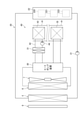
- FIG. 1 is a diagram schematically showing a schematic configuration of a vehicle according to the first embodiment.
- FIG. 2 is a block diagram showing a schematic configuration of the cooling circuit and the heat pump device of the first embodiment.
- FIG. 3 is a perspective view showing a schematic configuration of the shutter device of the first embodiment.
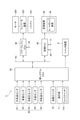
- FIG. 4 is a block diagram showing an electrical configuration of the vehicle of the first embodiment.
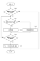
- FIG. 5 is a flowchart showing a procedure of processing executed by the thermal system ECU of the first embodiment.
- FIG. 6 is a diagram schematically showing a schematic configuration of a vehicle according to a second embodiment.
- 7 (A) and 7 (B) are diagrams schematically showing a schematic configuration of a vehicle according to a third embodiment and a fourth embodiment.
- FIG. 1 is a diagram schematically showing a schematic configuration of a vehicle according to the first embodiment.
- FIG. 2 is a block diagram showing a schematic configuration of the cooling circuit and the heat pump device of the first embodiment.
- FIG. 3 is
- FIG. 8 is a diagram schematically showing a schematic configuration of a vehicle according to a fifth embodiment.
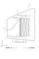
- FIG. 9 is a diagram schematically showing the front structure of the radiator of the fifth embodiment.
- FIG. 10 is a diagram schematically showing a schematic configuration of a vehicle according to a sixth embodiment.
- the vehicle C shown in FIG. 1 is a so-called electric vehicle that travels by using a motor as a power source.
- a grill opening 2 is provided in front of the body 1 of the vehicle C.
- the grill opening 2 is provided to supply the air in front of the vehicle body 1 to the radiator 5 and the outdoor heat exchanger 6.
- the air introduced from the grill opening 2 is supplied to the radiator 5 and the outdoor heat exchanger 6 through the air duct 4.
- the radiator 5 is a component of a cooling circuit for cooling the power unit of the vehicle C, and is a cooling water by exchanging heat between the cooling water circulating in the cooling circuit and the air introduced from the grill opening 2. Dissipate heat.
- the power unit includes a motor that is a power source of the vehicle C, a battery for driving the motor, an inverter device, and the like.
- the outdoor heat exchanger 6 is a component of the heat pump device provided in the air conditioner mounted on the vehicle C, and exchanges heat between the refrigerant circulating in the heat pump device and the air introduced from the grill opening 2. Operates as a condenser or heat exchanger.
- the radiator 5 is arranged in front of the vehicle with respect to the outdoor heat exchanger 6.
- a blower 7 is provided downstream of the outdoor heat exchanger 6 in the air flow direction.
- the blower 7 is provided, for example, to supply air to the radiator 5 and the outdoor heat exchanger 6 when the vehicle C is stopped.
- the radiator 5 and the outdoor heat exchanger 6 correspond to heat exchangers.
- the shutter device 8 is arranged in front of the radiator 5 so as to face each other.
- the shutter device 8 can switch between an open state in which the air introduced from the grill opening 2 can flow to the radiator 5 and the outdoor heat exchanger 6 and a closed state in which the air flow to them is blocked. It is configured in.
- the shutter device 8 improves the aerodynamic performance of the vehicle C, for example, by closing the shutter device 8 when the vehicle C travels at high speed.
- the shutter device 8 corresponds to a switchgear.
- the cooling circuit 20 is provided with a radiator 5, a pump 21, and a heating element 22.
- cooling water circulates through these elements.
- the radiator 5 cools the cooling water by exchanging heat between the cooling water flowing inside the radiator 5 and the air flowing outside the radiator 5.
- the pump 21 sucks in the cooling water cooled by the radiator 5 and discharges it to the heating element 22. Cooling water circulates in the cooling circuit 20 by driving the pump 21.
- the pump 21 is an electric pump that is driven based on the supply of electric power.
- the heating element 22 includes a motor 220, an inverter device 221, a battery 222, and the like that constitute the power unit of the vehicle C.
- the inverter device 221 converts the DC power charged in the battery 222 into AC power and supplies it to the motor 220, and also converts the AC power generated by the regenerative operation of the motor 220 into DC power to charge the battery 222. do.
- Cooling water discharged from the pump 21 flows through the motor 220, the inverter device 221 and the battery 222.
- the cooling water absorbs heat from the motor 220 and the like to cool them.
- the cooling water whose temperature has risen by absorbing the heat of the motor 220 or the like is supplied to the radiator 5 to be cooled again.
- the heat pump device 30 is a component of the air conditioner 40 of the vehicle C.
- the heat pump device 30 is provided with an outdoor heat exchanger 6, a water cooling condenser 31, and an evaporator 32.
- the refrigerant circulates through these elements.
- the heat pump device 30 cools and heats the interior of the vehicle by changing the flow state of the refrigerant depending on whether the air conditioner 40 is operating in the cooling mode or the air conditioner 40 is operating in the heating mode. To realize.
- the heat pump device 30 circulates the refrigerant through the outdoor heat exchanger 6 and the evaporator 32.
- the outdoor heat exchanger 6 operates as a capacitor. That is, the outdoor heat exchanger 6 cools the refrigerant by exchanging heat between the refrigerant flowing inside the outdoor heat exchanger 6 and the air flowing outside the outdoor heat exchanger 6.
- the high-pressure liquid-phase refrigerant generated by being cooled by the outdoor heat exchanger 6 is decompressed through a pressure reducing valve provided in the heat pump device 30 to change to a low-pressure liquid-phase refrigerant, and then is supplied to the evaporator 32.
- the evaporator 32 cools the air in the air conditioning duct 41 by exchanging heat between the refrigerant flowing inside the evaporator 32 and the air flowing in the air conditioning duct 41 of the air conditioning device 40.
- the air is blown into the vehicle interior through the air conditioning duct 41 to cool the vehicle interior.
- the low-pressure liquid-phase refrigerant transitions to the low-pressure gas-phase refrigerant by heat exchange with air.
- the low-pressure gas-phase refrigerant is compressed by a pump provided in the heat pump device 30 to transition to high-temperature and high-pressure gas-phase refrigerant, and then supplied to the outdoor heat exchanger 6 to be cooled again.
- the heat pump device 30 circulates the refrigerant through the outdoor heat exchanger 6 and the water cooling condenser 31.
- the outdoor heat exchanger 6 operates as a heat absorber. That is, the outdoor heat exchanger 6 heats the refrigerant by exchanging heat between the refrigerant flowing inside the outdoor heat exchanger 6 and the air flowing outside the refrigerant.
- the low-pressure gas-phase refrigerant generated by heating by the outdoor heat exchanger 6 is supplied to the water-cooled condenser 31 after transitioning to high-temperature and high-pressure gas-phase refrigerant through a pump provided in the heat pump device 30.
- the water-cooled condenser 31 heats the cooling water by exchanging heat between the high-temperature and high-pressure gas-phase refrigerant supplied from the heat pump device 30 and the cooling water flowing through the cooling water circuit 42 of the air conditioning device 40.
- the cooling water circuit 42 is provided with a heater core 43 of the air conditioner 40 and a pump 44.
- the pump 44 circulates the cooling water in the cooling water circuit 42.
- the heater core 43 heats the air flowing in the air conditioning duct 41 by exchanging heat between the cooling water flowing inside the heater core 43 and the air flowing in the air conditioning duct 41. The air is blown into the vehicle interior through the air conditioning duct 41 to heat the vehicle interior.
- heat exchange with the cooling water causes the high-temperature and high-pressure gas-phase refrigerant to transition to the high-pressure liquid-phase refrigerant.
- the high-pressure liquid-phase refrigerant is depressurized through a pressure reducing valve provided in the heat pump device 30 to transition to a low-pressure liquid-phase refrigerant, and then supplied to the outdoor heat exchanger 6 to be heated again.
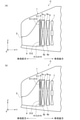
- the shutter device 8 includes a frame 50, a plurality of blades 51, and a motor 52.
- the frame 50 has a frame main body portion 500 formed in a rectangular frame shape, and a vertical frame reinforcing portion 501 and a horizontal frame reinforcing portion 502 arranged in a cross shape inside the frame main body portion 500. Air introduced from the grill opening 2 shown in FIG. 1 flows in the space inside the frame main body 500 in the direction indicated by the arrow Y.
- the longitudinal direction X of the frame main body 500 is also referred to as a left-right direction
- the lateral direction Z of the frame main body 500 is also referred to as a vertical direction
- the direction indicated by the arrow Y orthogonal to both the left-right direction X and the up-down direction Z is also referred to as "air flow direction Y”.
- the vertical frame reinforcing portion 501 is provided to reinforce the frame main body portion 500.
- the horizontal frame reinforcing portion 502 is provided to reinforce the frame main body portion 500 and hold the blade 51.
- the space inside the frame main body 500 is divided into four opening regions A11 to A14 by the vertical frame reinforcing portion 501 and the horizontal frame reinforcing portion 502.
- the two opening regions A11 and A12 arranged above the horizontal frame reinforcing portion 502 will be referred to as “upper opening regions A11 and A12", and the horizontal frame reinforcing portion will be referred to.
- the two opening regions A13 and A14 arranged below the 502 are referred to as “lower opening regions A13 and A14".
- the substantially lower halves of the lower opening regions A13 and A14 are located so as to face the grill opening 2.
- the opening area of the grill opening 2 is smaller than the front projected area of each of the radiator 5 and the outdoor heat exchanger 6.
- the lower opening regions A13 and A14 correspond to the first portion.
- the upper opening regions A11 and A12 correspond to the second portion farther from the grill opening 2 than the first portion.
- the upper portion 5a of the radiator 5 and the upper portion 6a of the outdoor heat exchanger 6 are arranged so as to face the upper opening regions A11 and A12 of the shutter device 8.
- the lower portion 5b, which is a portion of the radiator 5 excluding the upper portion 5a, and the lower portion 6b, which is a portion of the outdoor heat exchanger 6 excluding the upper portion 6a, are arranged so as to face the lower opening regions A13 and A14 of the shutter device 8. ..
- the two-dot chain line described in the radiator 5 of FIG. 1 indicates a boundary portion between the upper portion 5a and the lower portion 5b of the radiator 5.
- the two-dot chain line described in the outdoor heat exchanger 6 indicates the boundary portion between the upper portion 6a and the lower portion 6b of the outdoor heat exchanger 6.
- the plurality of blades 51 are arranged in the four opening regions A11 to A14 of the frame 50, respectively.
- the plurality of blades 51 are arranged so as to have a longitudinal direction in the vertical direction Z, and are arranged side by side in the left-right direction X.
- the blades 51 arranged in the upper opening areas A11 and A12 of the frame main body 500 are referred to as "upper blades 511", and the blades arranged in the lower opening areas A13 and A14.
- 51 is referred to as "lower blade 512".
- the blade 51 corresponds to the opening / closing portion
- the lower blade 512 corresponds to the first opening / closing portion
- the upper blade 511 corresponds to the second opening / closing portion.
- the motor 52 is fixed to one end of the upper surface of the frame main body 500 with screws or the like.
- the motor 52 rotates each of the blades 511 and 512 by applying a rotational force to the upper blades 511 and the lower blades 512 via a link mechanism (not shown).
- the shutter device 8 of the present embodiment can independently control the opening degrees of the upper blade 511 and the lower blade 512.
- the vehicle C is provided with various sensors 60 for detecting the traveling state, the state of the cooling circuit 20, the state of the heat pump device 30, the environmental state inside and outside the vehicle C, and the like. ..
- the sensor 60 includes an outside air temperature sensor 61, a vehicle speed sensor 62, a refrigerant pressure sensor 63, a water temperature sensor 64, an inside air temperature sensor 65, an outside air temperature sensor 66, and the like.
- the outside air temperature sensor 61 detects the temperature of the outside air, which is the air outside the vehicle C.
- the vehicle speed sensor 62 detects the vehicle speed, which is the traveling speed of the vehicle C.
- the refrigerant pressure sensor 63 detects the pressure of the refrigerant flowing out of the outdoor heat exchanger 6 in the heat pump device 30.
- the water temperature sensor 64 detects the temperature of the cooling water flowing out of the heating element 22 in the cooling circuit 20.
- the internal air temperature sensor 65 detects the internal air temperature, which is the temperature inside the vehicle C. Each sensor 61 to 65 outputs a signal according to the detected physical quantity.
- the vehicle C is provided with a start switch 70 that is operated when the vehicle C is started, and an operation unit 71 for operating the air conditioner 40.
- the operation unit 71 includes an A / C switch 710 that is operated when cooling or dehumidifying the vehicle interior.
- the vehicle C is further provided with a power train ECU (Electronic Control Unit) 80, an air conditioning ECU 81, and a thermal system ECU 82.
- the ECUs 80 to 82 are mainly composed of a microcomputer having a CPU, a ROM, a RAM, and the like.
- the ECUs 80 to 82 execute various controls by executing a program stored in advance in the ROM.
- Each ECU 80 to 82 can exchange various information with each other by using a network communication Nc such as CAN provided in the vehicle C.
- the power train ECU 80 is a part that comprehensively controls the running state of the vehicle C. For example, when the power train ECU 80 detects that the start switch 70 is turned on, the motor 220 is based on the accelerator position detected by the accelerator position sensor during the period until the start switch 70 is turned off. Set the target output torque. Then, the power train ECU 80 sets the target energization amount of the motor 220 based on the target output torque, and drives the inverter device 221 so that the actual energization amount of the motor 220 follows the target energization amount. The power train ECU 80 controls the traveling state of the vehicle C through such energization control of the motor 220.
- the air conditioning ECU 81 is a part that comprehensively controls the air conditioning device 40.
- the air conditioning ECU 81 captures the output signals of the internal air temperature sensor 65 and the operation unit 71, respectively.
- the air conditioning ECU 81 cools or dehumidifies the vehicle interior by operating the heat pump device 30 shown in FIG. 2 in the cooling mode.
- the air conditioning ECU 81 heats the interior of the vehicle by operating the heat pump device 30 shown in FIG. 2 in the heating mode. I do.
- the heating temperature determination value is a preset temperature, and is set to, for example, "15 [° C.]".
- the heat system ECU 82 is a part that mainly controls the air volume of air supplied to the radiator 5 and the outdoor heat exchanger 6 by driving the shutter device 8 to open and close.
- the thermal system ECU 82 incorporates the output signals of the various sensors 60, the start switch 70, and the operation unit 71.
- the thermal system ECU 82 detects various state quantities based on the output signals of the sensor 60, and also detects the operating states based on the output signals of the start switch 70 and the operation unit 71.
- the thermal system ECU 82 has a target opening degree of each of the upper blade 511 and the lower blade 512 of the shutter device 8 based on various state quantities detected by the sensor 60 and the operation states of the start switch 70 and the operation unit 71.
- the thermal system ECU 82 corresponds to the control unit that controls the shutter device 8.
- the thermal system ECU 82 repeatedly executes the process shown in FIG. 5 at a predetermined cycle.
- the thermal system ECU 82 sets the positions of the upper blade 511 and the lower blade 512 of the shutter device 8 to the initial positions when the process shown in FIG. 5 is started.
- the initial position is, for example, a position corresponding to a fully closed state.
- the thermal system ECU 82 first determines whether or not the start switch 70 has been turned on as the process of step S10. When the start switch 70 is not turned on, the thermal system ECU 82 makes a negative determination in the process of step S10, and temporarily ends the process shown in FIG.
- the thermal system ECU 82 makes a positive judgment in the process of step S10, and supplies air to the radiator 5 and the outdoor heat exchanger 6 as the process of the subsequent step S11. Determine if it is necessary. For example, the thermal system ECU 82 determines that it is not necessary to supply air to the radiator 5 and the outdoor heat exchanger 6 based on the fact that both the conditions shown in the following (a1) and (a2) are satisfied.
- (A1) When the A / C switch 710 is not turned on and the internal air temperature detected by the internal air temperature sensor 65 is higher than the heating temperature determination value. That is, when it is not necessary to operate the heat pump device 30 in either the cooling mode or the heating mode.
- (A2) When the temperature of the cooling water detected by the water temperature sensor 64 is equal to or lower than a predetermined temperature determination value. That is, when it is not necessary to cool the heating element 22.
- the temperature determination value is set in advance to a value that can determine whether or not the heating element 22 should be cooled.
- the temperature determination value is individually set for each cooling water temperature. May be set.
- the temperature determination value for the cooling water temperature of the motor 220 is set to, for example, "65 [° C.]”
- the temperature determination value for the cooling water temperature of the battery 222 is set, for example, "40 [° C.]”.
- the thermal system ECU 82 determines that it is not necessary to supply air to the radiator 5 and the outdoor heat exchanger 6, and processes in step S11. Make a negative decision.
- the thermal system ECU 82 executes a fully closed control for making the upper opening regions A11 and A12 and the lower opening regions A13 and A14 of the shutter device 8 fully closed.
- the thermal system ECU 82 drives the motor 52 so that both the upper blade 511 and the lower blade 512 are fully closed.
- the introduction of air through the grill opening 2 is blocked, so that the aerodynamic performance of the vehicle C can be improved. Therefore, the electricity cost of the vehicle C can be improved.
- the heat system ECU 82 needs to supply air to at least one of the radiator 5 and the outdoor heat exchanger 6. to decide.
- the condition (a1) when the condition (a1) is not satisfied, there are cases where the A / C switch 710 is not turned on and cases where the internal air temperature detected by the internal air temperature sensor 65 is equal to or less than the heating temperature determination value. exist.
- the heat pump device 30 since the heat pump device 30 needs to be operated in the cooling mode, it is necessary to supply air to the outdoor heat exchanger 6. Further, in the latter case, since the heat pump device 30 needs to be operated in the heating mode, it is necessary to supply air to the outdoor heat exchanger 6.
- condition (a2) is not satisfied, that is, when the temperature of the cooling water of the heating element 22 exceeds a predetermined temperature determination value, the cooling circuit 20 is driven to cool the heating element 22. Since it is necessary, it is necessary to supply air to the radiator 5.
- the thermal system ECU 82 determines that at least one of the above conditions (a1) and (a2) is not satisfied and it is necessary to supply air to at least one of the radiator 5 and the outdoor heat exchanger 6. Makes a positive judgment in the process of step S11, and executes opening degree adjustment control for adjusting the opening degree of each of the upper blade 511 and the lower blade 512 of the shutter device 8 as the subsequent process of step S13.
- both the upper blade 511 and the lower blade 512 are opened, and as shown in FIG. 1, the opening of the upper blade 511 is larger than the opening of the lower blade 512.
- the motor 52 is driven so as to be smaller.
- both the upper blade 511 and the lower blade 512 are opened, air can be supplied to the radiator 5 and the outdoor heat exchanger 6, so that the cooling circuit 20 and the heat pump device 30 can be driven. ..
- step S12 or step S13 the thermal system ECU 82 determines whether or not the start switch 70 has been turned off as the process of step S14. If the start switch 70 is not turned off, the thermal system ECU 82 makes a negative determination in the process of step S14, and returns to the process of step S11. On the other hand, when the thermal system ECU 82 makes a positive judgment in the process of step S14, that is, when the start switch 70 is turned off, the upper blade 511 and the lower blade 512 are processed in step S15. Is displaced to the initial position, and then the process shown in FIG. 5 is temporarily terminated.
- the actions and effects shown in the following (1) to (5) can be obtained.
- the shutter device 8 includes one motor 52 that operates the upper blade 511 and the lower blade 512. According to this configuration, the number of parts can be reduced as compared with the configuration in which the motor for operating the upper blade 511 and the motor for operating the lower blade 512 are separately provided.
- the shutter device 8 is arranged immediately before the radiator 5 in the air flow direction. According to this configuration, the shutter device 8 can be installed by utilizing the space provided in front of the radiator 5.
- the width H11 of the grill opening 2 in the vertical direction Z of the vehicle C is larger than the width H12 of the lower opening regions A13 and A14 of the shutter device 8 in the vertical direction Z of the vehicle C. short. If the width of the grill opening 2 is set short as in this configuration, the amount of air taken into the air guide duct 4 can be reduced, so that the aerodynamic performance of the vehicle C can be improved.
- the thermal system ECU 82 displaces the upper blade 511 and the lower blade 512 to the initial positions when the start switch 70 of the vehicle C is turned off. According to this configuration, each time the start switch 70 is turned off, the positions of the upper blade 511 and the lower blade 512 can be corrected.
- the thermal system ECU 82 controls the opening degrees of the upper blade 511 and the lower blade 512 according to the operating states of the radiator 5 and the outdoor heat exchanger 6. According to this configuration, it is possible to realize a more appropriate air flow according to the operating states of the radiator 5 and the outdoor heat exchanger 6.
- the vehicle C of the second embodiment will be described.
- the differences from the vehicle C of the first embodiment will be mainly described.
- the heat pump device 30 operates in the heating mode in an environment where the outside air temperature is low.
- the adhered water may freeze and the blades 511, 512 of the shutter device 8 may not be able to open and close.
- the indicator of the vehicle C may light up and the driver may be confused. be.
- the lower blade 512 arranged near the grill opening 2 is easily exposed to water, while the upper blade 511 arranged away from the grill opening 2 is less likely to be exposed to water.
- the lower blade 512 is kept in a closed state, while if only the upper blade 511 is opened and closed, the lower blade 512 is tentatively covered. Even if it is frozen by water, air can be supplied to the outdoor heat exchanger 6 through the upper opening regions A11 and A12. Therefore, the heat pump device 30 can be operated in the heating mode.
- the thermal system ECU 82 controls the shutter device 8 as follows.
- the heat system ECU 82 of the present embodiment acquires information on the operating state of the heat pump device 30 from the air conditioning ECU 81.
- the thermal system ECU 82 determines whether or not the heat pump device 30 is operating in the heating mode and the outside air temperature detected by the outside air temperature sensor 61 is equal to or lower than the freezing determination temperature in the process of step S13 shown in FIG. to decide.
- the freezing determination temperature is a temperature determination value for determining whether or not the water has a possibility of freezing when it adheres to the shutter device 8, and is, for example, "5 [° C.]". It is preset.
- the heat system ECU 82 determines that the outside air temperature detected by the outside air temperature sensor 61 is equal to or lower than the freezing determination temperature
- the heat system ECU 82 is on the upper side as shown in FIG.
- the motor 52 is driven so that the blade 511 is in the open state and the lower blade 512 is in the closed state.
- the heat pump device 30 can be operated in the heating mode even in an environment where the shutter device 8 is likely to freeze due to water exposure. Therefore, since the heating inside the vehicle interior can be continued, the comfort inside the vehicle interior can be ensured.
- the outdoor heat exchanger 6 is usually configured to include a plurality of tubes and tanks connected to both ends of the tubes. In the outdoor heat exchanger 6, heat exchange is performed between the refrigerant flowing inside each tube and the air flowing outside each tube. In the outdoor heat exchanger 6 having such a configuration, if frost adheres to the surface of the tube, the heat transfer area for air is substantially reduced, so that the heat exchange efficiency may be significantly reduced. Therefore, some heat pump devices 30 operate in a so-called defrosting mode in which frost is melted when frost adheres to the surface of the tube of the outdoor heat exchanger 6.
- the refrigerant is circulated in the outdoor heat exchanger 6 in a state where the supply of air to the outdoor heat exchanger 6 is cut off.
- the frost adhering to the surface of the tube can be melted by the heat of the refrigerant.
- both the upper blade 511 and the lower blade 512 of the shutter device 8 may be closed.
- air cannot be supplied to the outdoor heat exchanger 6, so that the heat pump device 30 cannot be operated in the heating mode. That is, since it is not possible to heat the interior of the vehicle, the comfort of the interior of the vehicle may be impaired.
- the heat system ECU 82 of the present embodiment acquires the information on the operating state of the heat pump device 30 from the air conditioning ECU 81, and then the heat pump device 30 operates in the defrosting mode. If it is determined that the control is present, the controls shown in (b1) and (b2) below are alternately executed at predetermined time intervals.
- the attached frost can be melted by the heat of the refrigerant in that portion. That is, the upper portion 6a functions as a defrosting area, and the lower portion 6b functions as an endothermic area. According to this configuration, the frost adhering to the upper portion 6a and the lower portion 6b of the outdoor heat exchanger 6 can be removed together, so that the deterioration of the performance of the outdoor heat exchanger 6 due to the adhesion of the frost can be avoided. can. Further, since the outdoor heat exchanger 6 can be continuously used as a heat absorber, continuous heating of the vehicle interior becomes possible.
- the heat system ECU 82 of the present embodiment further executes a drainage mode of removing water from the surface of the outdoor heat exchanger 6 after the heat pump device 30 operates in the defrosting mode.
- the thermal system ECU 82 alternately executes the controls shown in the above (b1) and (b2) at predetermined time intervals as the drainage mode.
- the control of the above (b1) is switched to the control of the above (b2)
- the lower portion 6b of the outdoor heat exchanger 6 is switched from the state in which no air is flowing to the state in which air is flowing. .. Therefore, the air volume of the air flowing through the lower portion 6b of the outdoor heat exchanger 6 can be changed rapidly.
- the heat system ECU 82 executes a drainage mode in which the air volume of the air passing through the upper portion 6a and the lower portion 6b of the outdoor heat exchanger 6 is rapidly changed after the heat pump device 30 operates in the defrosting mode. Remove the water accumulated in the outdoor heat exchanger 6. As a result, the water accumulated in the outdoor heat exchanger 6 can be removed by executing the defrosting mode, so that it is possible to avoid a decrease in heat exchange efficiency of the outdoor heat exchanger 6 and freezing cracking.
- the vehicle C of the fifth embodiment will be described.
- the differences from the vehicle C of the first embodiment will be mainly described.
- the radiator 5 and the outdoor heat exchanger 6 are thermally connected via the outer fin 9. That is, heat exchange is possible between the radiator 5 and the outdoor heat exchanger 6 via the outer fin 9.
- the outdoor heat exchanger 6 when the outdoor heat exchanger 6 is operating as a heat absorber, the waste heat of the radiator 5 can be transferred to the outdoor heat exchanger 6 via the outer fins 9, so that the vehicle C as a whole can be assured. Thermal efficiency can be increased. As a result, it becomes possible to improve the electricity cost of the vehicle C.
- the radiator 5 is configured such that the cooling water flows in a U shape from the lower portion 5b to the upper portion 5a.
- the temperature of the cooling water flowing inside the radiator 5 decreases toward the downstream side. That is, the temperature of the upper portion 5a of the radiator 5 is lower than the temperature of the lower portion 5b of the radiator 5. Therefore, the outdoor heat exchanger 6 may be able to absorb the required amount of heat from the lower portion 5b of the radiator 5, but may not be able to absorb the required amount of heat from the upper portion 5a of the radiator 5.
- the heat system ECU 82 of the present embodiment is shown in FIG. 8 when the heat absorption amount of the outdoor heat exchanger 6 is insufficient only by transferring the heat of the radiator 5 to the outdoor heat exchanger 6 via the outer fin 9.
- the motor 52 is driven so that the upper blade 511 is in the open state and the lower blade 512 is in the closed state.
- the waste heat of the radiator 5 can be absorbed through the outer fin 9 at the lower portion 6b thereof, while the insufficient amount of heat can be absorbed from the air at the upper portion 6a thereof.
- the required amount of heat absorption can be secured for the outdoor heat exchanger 6 as a whole.
- the actions and effects shown in (10) below can be obtained.
- the outdoor heat exchanger 6 When the outdoor heat exchanger 6 is operating as a heat absorber that absorbs the heat of the radiator 5 into the refrigerant via the outer fin 9, the heat system ECU 82 sets the upper blade 511 to the open state, while lowering it. Set the side blade 512 to the closed state. According to this configuration, the amount of heat absorbed by the outdoor heat exchanger 6 can be secured more accurately, so that the interior of the vehicle can be appropriately heated. Therefore, the comfort in the vehicle interior can be ensured.
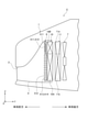
- the vehicle C of the sixth embodiment will be described.
- the differences from the vehicle C of the first embodiment will be mainly described.
- the vehicle C of the present embodiment is equipped with a multifunction heat exchanger 10 in place of the radiator 5 and a radiator 11 in place of the outdoor heat exchanger 6.
- the multifunctional heat exchanger 10 has a first heat exchange unit 10A at the lower portion thereof and a second heat exchange unit 10B at the upper portion thereof.
- the first heat exchange unit 10A is used as the outdoor heat exchanger 6 of the heat pump device 30 described above.
- the first heat exchange unit 10A is arranged so as to face the lower opening regions A13 and A14 of the shutter device 8.
- Cooling water for cooling the battery 222 flows inside the second heat exchange unit 10B.
- the second heat exchange unit 10B cools the cooling water by exchanging heat between the cooling water flowing inside the cooling water and the air flowing outside the cooling water.
- the second heat exchange unit 10B is arranged so as to face the upper opening regions A11 and A12 of the shutter device 8.
- Cooling water for cooling the motor 220 is flowing inside the radiator 11.
- the radiator 11 cools the cooling water by exchanging heat between the cooling water flowing inside the radiator 11 and the air flowing outside the radiator 11.
- the upper portion 11a of the radiator 11 is arranged so as to face the upper opening regions A11 and A12 of the shutter device 8.
- the lower portion 11b of the radiator 11 is arranged so as to face the lower opening regions A13 and A14.
- the cooling circuit for cooling the motor 220 and the cooling circuit for cooling the battery 222 are independently provided.
- the radiator 11 it is possible to cool the cooling water having a temperature higher than that of the second heat exchange unit 10B.
- the motor 220 corresponds to the first heating element and the battery 222 corresponds to the second heating element.
- the thermal system ECU 82 drives the motor 52 so that the upper blade 511 is in the closed state and the lower blade 512 is in the open state, as shown in FIG. ..
- the air introduced from the grill opening 2 flows only to the first heat exchange section 10A of the multifunction heat exchanger 10, so that it flows to both the first heat exchange section 10A and the second heat exchange section 10B.
- the air volume of the air flowing through the first heat exchange unit 10A can be increased.
- the thermal system ECU 82 may drive the motor 52 so that the upper blade 511 is in the open state and the lower blade 512 is in the closed state when the heat pump device 30 is stopped. According to the vehicle C of the present embodiment described above, the actions and effects shown in (11) below can be obtained.
- the thermal system ECU 82 sets the lower blade 512 to the open state and the upper blade 511 to the closed state when cooling of the battery 222 is not required. According to this configuration, air is not supplied to the first heat exchange section 10A of the multifunctional heat exchanger 10 that does not require heat exchange with air, and the second heat exchange of the multifunctional heat exchanger 10 is corresponding to that amount.
- the air volume of the air supplied to the portion 10B can be increased. Therefore, for example, when the first heat exchange unit 10A is used as a capacitor in the heat pump device 30, the refrigerant flowing through the first heat exchange unit 10A can be cooled more accurately, so that the cooling efficiency of the refrigerant is improved. be able to. Therefore, it is possible to reduce the size of the first heat exchange unit 10A.
- a configuration of the vehicle C of the fifth embodiment that is, a configuration in which the radiator 5 and the outdoor heat exchanger 6 are thermally connected via the outer fins 9 is applied to the vehicle C of the third embodiment. May be good.
- the heat pump device 30 utilizes the heat of the refrigerant circulating inside the outdoor heat exchanger 6 when executing the defrosting mode for removing the frost adhering to the surface of the outdoor heat exchanger 6.
- this method it is possible to use a method of utilizing the heat transferred from the radiator 5 to the outdoor heat exchanger 6 via the outer fins 9.
- the shutter device 8 is not limited to having two opening / closing portions such as an upper blade 511 and a lower blade 512, and may have three or more opening / closing portions.
- the shutter device 8 may be arranged between the radiator 5 and the outdoor heat exchanger 6 or immediately after the air flow direction with respect to the outdoor heat exchanger 6.
- the vehicle C of the first to fifth embodiments uses a shutter device 8 arranged in front of the radiator 5 as a switchgear for changing the air volume of the air supplied to the radiator 5 and the outdoor heat exchanger 6. there were.
- a shutter mechanism having the same or similar function as the shutter device 8 may be provided in the fan shroud of the blower 7.
- the shutter mechanism provided in the blower 7 corresponds to the switchgear.
- the vehicle C of the sixth embodiment uses a shutter device 8 arranged in front of the radiator 5 as a switchgear for changing the air volume of the air supplied to the radiator 5 and the outdoor heat exchanger 6.
- the thermal system ECU 82 and methods thereof according to the present disclosure are provided by configuring a processor and memory programmed to perform one or more functions embodied by a computer program. It may be realized by a plurality of dedicated computers.
- the thermal system ECU 82 and its control method described in the present disclosure may be realized by a dedicated computer provided by configuring a processor including one or more dedicated hardware logic circuits.
- the thermal system ECU 82 and its control method described in the present disclosure comprises a combination of a processor and memory programmed to perform one or more functions and a processor including one or more hardware logic circuits. It may be realized by one or more dedicated computers.
- the computer program may be stored on a computer-readable non-transitional tangible recording medium as an instruction executed by the computer.
- the dedicated hardware logic circuit and the hardware logic circuit may be realized by a digital circuit including a plurality of logic circuits or an analog circuit.
- each embodiment is not limited to electric vehicles, but can also be applied to hybrid vehicles and plug-in hybrid vehicles.
- the configurations of the second to fourth embodiments and the sixth embodiment are applicable to the hybrid vehicle.
- the configurations of the first to fourth embodiments and the sixth embodiment can be applied to the plug-in hybrid vehicle.
Abstract
L'invention concerne un véhicule (C) qui comprend des échangeurs de chaleur (5, 6) qui échangent de la chaleur avec l'air introduit à partir d'une partie d'ouverture de grille (2), un dispositif d'ouverture/fermeture (8) qui peut modifier le volume d'air de l'air fourni aux échangeurs de chaleur et une unité de commande (82) qui commande le dispositif d'ouverture/fermeture. Le dispositif d'ouverture/fermeture comprend, en tant que parties d'ouverture/fermeture, une première partie d'ouverture/fermeture (512) qui ouvre et ferme des premières parties (A13, A14) du dispositif d'ouverture/fermeture et une seconde partie d'ouverture/fermeture (511) qui ouvre et ferme des secondes parties (A11, A12) espacées davantage de la partie d'ouverture de grille que les premières parties. L'unité de commande fait fonctionner la première partie d'ouverture/fermeture et la seconde partie d'ouverture/fermeture de telle sorte que le degré d'ouverture des premières parties soit inférieur au degré d'ouverture des secondes parties.
Priority Applications (1)
| Application Number | Priority Date | Filing Date | Title |
|---|---|---|---|
| CN202180061903.9A CN116056924A (zh) | 2020-09-11 | 2021-08-17 | 车辆 |
Applications Claiming Priority (2)
| Application Number | Priority Date | Filing Date | Title |
|---|---|---|---|
| JP2020-153320 | 2020-09-11 | ||
| JP2020153320A JP2022047416A (ja) | 2020-09-11 | 2020-09-11 | 車両 |
Publications (1)
| Publication Number | Publication Date |
|---|---|
| WO2022054504A1 true WO2022054504A1 (fr) | 2022-03-17 |
Family
ID=80631519
Family Applications (1)
| Application Number | Title | Priority Date | Filing Date |
|---|---|---|---|
| PCT/JP2021/030001 WO2022054504A1 (fr) | 2020-09-11 | 2021-08-17 | Véhicule |
Country Status (3)
| Country | Link |
|---|---|
| JP (1) | JP2022047416A (fr) |
| CN (1) | CN116056924A (fr) |
| WO (1) | WO2022054504A1 (fr) |
Citations (10)
| Publication number | Priority date | Publication date | Assignee | Title |
|---|---|---|---|---|
| JP2000320331A (ja) * | 1999-03-11 | 2000-11-21 | Denso Corp | 車両用冷却装置 |
| US20110246023A1 (en) * | 2010-04-01 | 2011-10-06 | Gm Global Technoloy Operations, Inc. | Powertrain Thermal Control with Grille Airflow Shutters |
| US20140246863A1 (en) * | 2013-03-04 | 2014-09-04 | General Electric Company | System for cooling power generation system |
| JP2014223867A (ja) * | 2013-05-16 | 2014-12-04 | カルソニックカンセイ株式会社 | 車両用空調装置 |
| KR101575255B1 (ko) * | 2014-05-27 | 2015-12-07 | 현대자동차 주식회사 | 차량용 액티브 에어 플랩 |
| JP2016190533A (ja) * | 2015-03-31 | 2016-11-10 | カルソニックカンセイ株式会社 | 冷却システム |
| JP2019038275A (ja) * | 2017-08-22 | 2019-03-14 | マツダ株式会社 | エンジンの保温構造 |
| JP2019051900A (ja) * | 2017-09-19 | 2019-04-04 | 株式会社デンソー | 熱交換システム |
| JP2019214288A (ja) * | 2018-06-12 | 2019-12-19 | 株式会社デンソー | シャッター装置 |
| WO2020121923A1 (fr) * | 2018-12-14 | 2020-06-18 | 株式会社デンソー | Système d'échange de chaleur de véhicule |
-
2020
- 2020-09-11 JP JP2020153320A patent/JP2022047416A/ja active Pending
-
2021
- 2021-08-17 WO PCT/JP2021/030001 patent/WO2022054504A1/fr active Application Filing
- 2021-08-17 CN CN202180061903.9A patent/CN116056924A/zh active Pending
Patent Citations (10)
| Publication number | Priority date | Publication date | Assignee | Title |
|---|---|---|---|---|
| JP2000320331A (ja) * | 1999-03-11 | 2000-11-21 | Denso Corp | 車両用冷却装置 |
| US20110246023A1 (en) * | 2010-04-01 | 2011-10-06 | Gm Global Technoloy Operations, Inc. | Powertrain Thermal Control with Grille Airflow Shutters |
| US20140246863A1 (en) * | 2013-03-04 | 2014-09-04 | General Electric Company | System for cooling power generation system |
| JP2014223867A (ja) * | 2013-05-16 | 2014-12-04 | カルソニックカンセイ株式会社 | 車両用空調装置 |
| KR101575255B1 (ko) * | 2014-05-27 | 2015-12-07 | 현대자동차 주식회사 | 차량용 액티브 에어 플랩 |
| JP2016190533A (ja) * | 2015-03-31 | 2016-11-10 | カルソニックカンセイ株式会社 | 冷却システム |
| JP2019038275A (ja) * | 2017-08-22 | 2019-03-14 | マツダ株式会社 | エンジンの保温構造 |
| JP2019051900A (ja) * | 2017-09-19 | 2019-04-04 | 株式会社デンソー | 熱交換システム |
| JP2019214288A (ja) * | 2018-06-12 | 2019-12-19 | 株式会社デンソー | シャッター装置 |
| WO2020121923A1 (fr) * | 2018-12-14 | 2020-06-18 | 株式会社デンソー | Système d'échange de chaleur de véhicule |
Also Published As
| Publication number | Publication date |
|---|---|
| CN116056924A (zh) | 2023-05-02 |
| JP2022047416A (ja) | 2022-03-24 |
Similar Documents
| Publication | Publication Date | Title |
|---|---|---|
| JP7232638B2 (ja) | 電気自動車における温調制御システム | |
| JP7185469B2 (ja) | 車両の熱管理システム | |
| CN109383221B (zh) | 车辆的hvac系统 | |
| JP5624668B2 (ja) | 車両用空調システム | |
| WO2020031568A1 (fr) | Dispositif de climatisation de véhicule | |
| WO2020031569A1 (fr) | Dispositif de climatisation de véhicule | |
| JP2002352867A (ja) | 電気自動車のバッテリ温度制御装置 | |
| JP5817824B2 (ja) | 車両の空調装置 | |
| CN107614301B (zh) | 车辆用空调装置 | |
| JP2020055344A (ja) | 車両の熱管理システム | |
| US10562367B2 (en) | Heating, ventilation, and air conditioning system for vehicle | |
| JP2002354608A (ja) | 電気自動車のバッテリ冷却装置 | |
| JP6721007B2 (ja) | 冷却システム | |
| JP2008049876A (ja) | 車両用空調装置 | |
| JP7024537B2 (ja) | 冷却装置 | |
| JP2006120334A (ja) | バッテリ温度管理装置およびそれを備える自動車 | |
| JP5747701B2 (ja) | 組電池の温度調節装置 | |
| WO2019135334A1 (fr) | Appareil de refroidissement de véhicule | |
| CN113015638A (zh) | 车用空调装置 | |
| WO2022054504A1 (fr) | Véhicule | |
| JP2021088250A (ja) | 車両用エネルギーマネジメントシステム | |
| JP6849502B2 (ja) | 車両用冷却システム | |
| JPWO2012114426A1 (ja) | 車両用空調システム | |
| WO2018123325A1 (fr) | Module de commande | |
| WO2019021746A1 (fr) | Système de refroidissement |
Legal Events
| Date | Code | Title | Description |
|---|---|---|---|
| 121 | Ep: the epo has been informed by wipo that ep was designated in this application |
Ref document number: 21866464 Country of ref document: EP Kind code of ref document: A1 |
|
| NENP | Non-entry into the national phase |
Ref country code: DE |
|
| 122 | Ep: pct application non-entry in european phase |
Ref document number: 21866464 Country of ref document: EP Kind code of ref document: A1 |