WO2022050281A1 - プラスチック含有材料の分解方法、無機材料の回収方法、再生炭素繊維、及び再生炭素繊維の製造方法、混紡糸、当該混紡糸を含む炭素繊維強化熱可塑性樹脂ペレット、及びそれらの製造方法、炭素繊維強化熱可塑性樹脂ストランド、及びその製造方法、並びに炭素繊維強化熱可塑性ペレット - Google Patents
プラスチック含有材料の分解方法、無機材料の回収方法、再生炭素繊維、及び再生炭素繊維の製造方法、混紡糸、当該混紡糸を含む炭素繊維強化熱可塑性樹脂ペレット、及びそれらの製造方法、炭素繊維強化熱可塑性樹脂ストランド、及びその製造方法、並びに炭素繊維強化熱可塑性ペレット Download PDFInfo
- Publication number
- WO2022050281A1 WO2022050281A1 PCT/JP2021/032002 JP2021032002W WO2022050281A1 WO 2022050281 A1 WO2022050281 A1 WO 2022050281A1 JP 2021032002 W JP2021032002 W JP 2021032002W WO 2022050281 A1 WO2022050281 A1 WO 2022050281A1
- Authority
- WO
- WIPO (PCT)
- Prior art keywords
- carbon fiber
- plastic
- thermoplastic resin
- fiber
- less
- Prior art date
Links
- 229920000049 Carbon (fiber) Polymers 0.000 title claims abstract description 435
- 239000004917 carbon fiber Substances 0.000 title claims abstract description 435
- VNWKTOKETHGBQD-UHFFFAOYSA-N methane Chemical compound C VNWKTOKETHGBQD-UHFFFAOYSA-N 0.000 title claims abstract description 375
- 229920005992 thermoplastic resin Polymers 0.000 title claims abstract description 265
- 229920003023 plastic Polymers 0.000 title claims abstract description 232
- 239000004033 plastic Substances 0.000 title claims abstract description 232
- 239000000463 material Substances 0.000 title claims abstract description 229
- 238000000034 method Methods 0.000 title claims abstract description 197
- 239000004918 carbon fiber reinforced polymer Substances 0.000 title claims abstract description 188
- 239000008188 pellet Substances 0.000 title claims abstract description 125
- 238000004519 manufacturing process Methods 0.000 title claims abstract description 69
- 239000011147 inorganic material Substances 0.000 title claims abstract description 45
- 229910010272 inorganic material Inorganic materials 0.000 title claims abstract description 44
- -1 blended yarn Substances 0.000 title description 18
- 239000000835 fiber Substances 0.000 claims description 303
- 238000010438 heat treatment Methods 0.000 claims description 230
- 229910052760 oxygen Inorganic materials 0.000 claims description 165
- QVGXLLKOCUKJST-UHFFFAOYSA-N atomic oxygen Chemical compound [O] QVGXLLKOCUKJST-UHFFFAOYSA-N 0.000 claims description 163
- 239000001301 oxygen Substances 0.000 claims description 163
- 239000007789 gas Substances 0.000 claims description 102
- 229910052799 carbon Inorganic materials 0.000 claims description 101
- OKTJSMMVPCPJKN-UHFFFAOYSA-N Carbon Chemical compound [C] OKTJSMMVPCPJKN-UHFFFAOYSA-N 0.000 claims description 96
- 239000004065 semiconductor Substances 0.000 claims description 87
- 238000000354 decomposition reaction Methods 0.000 claims description 79
- 239000012298 atmosphere Substances 0.000 claims description 47
- 229920005989 resin Polymers 0.000 description 112
- 239000011347 resin Substances 0.000 description 112
- 239000000306 component Substances 0.000 description 100
- 239000000047 product Substances 0.000 description 41
- 230000000052 comparative effect Effects 0.000 description 26
- 238000011282 treatment Methods 0.000 description 26
- 239000002131 composite material Substances 0.000 description 24
- 238000011156 evaluation Methods 0.000 description 23
- 239000002994 raw material Substances 0.000 description 21
- 229920002430 Fibre-reinforced plastic Polymers 0.000 description 18
- 239000011151 fibre-reinforced plastic Substances 0.000 description 18
- 238000002411 thermogravimetry Methods 0.000 description 18
- 239000011230 binding agent Substances 0.000 description 17
- 238000000576 coating method Methods 0.000 description 17
- 230000001965 increasing effect Effects 0.000 description 17
- 230000020169 heat generation Effects 0.000 description 16
- 230000000704 physical effect Effects 0.000 description 16
- 238000009987 spinning Methods 0.000 description 16
- 238000002844 melting Methods 0.000 description 15
- 230000008018 melting Effects 0.000 description 15
- VZSRBBMJRBPUNF-UHFFFAOYSA-N 2-(2,3-dihydro-1H-inden-2-ylamino)-N-[3-oxo-3-(2,4,6,7-tetrahydrotriazolo[4,5-c]pyridin-5-yl)propyl]pyrimidine-5-carboxamide Chemical compound C1C(CC2=CC=CC=C12)NC1=NC=C(C=N1)C(=O)NCCC(N1CC2=C(CC1)NN=N2)=O VZSRBBMJRBPUNF-UHFFFAOYSA-N 0.000 description 14
- 239000011248 coating agent Substances 0.000 description 14
- 239000008358 core component Substances 0.000 description 14
- 238000005520 cutting process Methods 0.000 description 14
- 239000000805 composite resin Substances 0.000 description 13
- 238000000465 moulding Methods 0.000 description 13
- 230000001590 oxidative effect Effects 0.000 description 13
- 238000011084 recovery Methods 0.000 description 13
- MKYBYDHXWVHEJW-UHFFFAOYSA-N N-[1-oxo-1-(2,4,6,7-tetrahydrotriazolo[4,5-c]pyridin-5-yl)propan-2-yl]-2-[[3-(trifluoromethoxy)phenyl]methylamino]pyrimidine-5-carboxamide Chemical compound O=C(C(C)NC(=O)C=1C=NC(=NC=1)NCC1=CC(=CC=C1)OC(F)(F)F)N1CC2=C(CC1)NN=N2 MKYBYDHXWVHEJW-UHFFFAOYSA-N 0.000 description 12
- 238000004898 kneading Methods 0.000 description 12
- 230000008569 process Effects 0.000 description 12
- 238000012545 processing Methods 0.000 description 12
- 229920000742 Cotton Polymers 0.000 description 10
- AFCARXCZXQIEQB-UHFFFAOYSA-N N-[3-oxo-3-(2,4,6,7-tetrahydrotriazolo[4,5-c]pyridin-5-yl)propyl]-2-[[3-(trifluoromethoxy)phenyl]methylamino]pyrimidine-5-carboxamide Chemical compound O=C(CCNC(=O)C=1C=NC(=NC=1)NCC1=CC(=CC=C1)OC(F)(F)F)N1CC2=C(CC1)NN=N2 AFCARXCZXQIEQB-UHFFFAOYSA-N 0.000 description 10
- 239000004734 Polyphenylene sulfide Substances 0.000 description 10
- 238000009960 carding Methods 0.000 description 10
- 239000003822 epoxy resin Substances 0.000 description 10
- 239000007769 metal material Substances 0.000 description 10
- 229920000647 polyepoxide Polymers 0.000 description 10
- 229920000069 polyphenylene sulfide Polymers 0.000 description 10
- 230000004580 weight loss Effects 0.000 description 10
- NIPNSKYNPDTRPC-UHFFFAOYSA-N N-[2-oxo-2-(2,4,6,7-tetrahydrotriazolo[4,5-c]pyridin-5-yl)ethyl]-2-[[3-(trifluoromethoxy)phenyl]methylamino]pyrimidine-5-carboxamide Chemical compound O=C(CNC(=O)C=1C=NC(=NC=1)NCC1=CC(=CC=C1)OC(F)(F)F)N1CC2=C(CC1)NN=N2 NIPNSKYNPDTRPC-UHFFFAOYSA-N 0.000 description 9
- 229920001225 polyester resin Polymers 0.000 description 9
- 239000004645 polyester resin Substances 0.000 description 9
- CURLTUGMZLYLDI-UHFFFAOYSA-N Carbon dioxide Chemical compound O=C=O CURLTUGMZLYLDI-UHFFFAOYSA-N 0.000 description 8
- 238000000151 deposition Methods 0.000 description 8
- 230000000694 effects Effects 0.000 description 8
- 238000001746 injection moulding Methods 0.000 description 8
- 239000000203 mixture Substances 0.000 description 8
- 229920006287 phenoxy resin Polymers 0.000 description 8
- 239000013034 phenoxy resin Substances 0.000 description 8
- 229920001643 poly(ether ketone) Polymers 0.000 description 8
- 229920006122 polyamide resin Polymers 0.000 description 8
- 229920005668 polycarbonate resin Polymers 0.000 description 8
- 239000004431 polycarbonate resin Substances 0.000 description 8
- 229920005672 polyolefin resin Polymers 0.000 description 8
- 239000000155 melt Substances 0.000 description 7
- 238000005979 thermal decomposition reaction Methods 0.000 description 7
- HMUNWXXNJPVALC-UHFFFAOYSA-N 1-[4-[2-(2,3-dihydro-1H-inden-2-ylamino)pyrimidin-5-yl]piperazin-1-yl]-2-(2,4,6,7-tetrahydrotriazolo[4,5-c]pyridin-5-yl)ethanone Chemical compound C1C(CC2=CC=CC=C12)NC1=NC=C(C=N1)N1CCN(CC1)C(CN1CC2=C(CC1)NN=N2)=O HMUNWXXNJPVALC-UHFFFAOYSA-N 0.000 description 6
- IJGRMHOSHXDMSA-UHFFFAOYSA-N Atomic nitrogen Chemical compound N#N IJGRMHOSHXDMSA-UHFFFAOYSA-N 0.000 description 6
- 229920002302 Nylon 6,6 Polymers 0.000 description 6
- 239000004743 Polypropylene Substances 0.000 description 6
- 238000005452 bending Methods 0.000 description 6
- 229910001873 dinitrogen Inorganic materials 0.000 description 6
- 238000010030 laminating Methods 0.000 description 6
- 229910052751 metal Inorganic materials 0.000 description 6
- 239000002184 metal Substances 0.000 description 6
- 229920000139 polyethylene terephthalate Polymers 0.000 description 6
- 239000005020 polyethylene terephthalate Substances 0.000 description 6
- 239000004626 polylactic acid Substances 0.000 description 6
- 229920001155 polypropylene Polymers 0.000 description 6
- 238000007665 sagging Methods 0.000 description 6
- 241000209094 Oryza Species 0.000 description 5
- 235000007164 Oryza sativa Nutrition 0.000 description 5
- WGLPBDUCMAPZCE-UHFFFAOYSA-N Trioxochromium Chemical compound O=[Cr](=O)=O WGLPBDUCMAPZCE-UHFFFAOYSA-N 0.000 description 5
- 229910000423 chromium oxide Inorganic materials 0.000 description 5
- 239000006185 dispersion Substances 0.000 description 5
- 239000003365 glass fiber Substances 0.000 description 5
- 239000011159 matrix material Substances 0.000 description 5
- 230000003647 oxidation Effects 0.000 description 5
- 238000007254 oxidation reaction Methods 0.000 description 5
- 229920000747 poly(lactic acid) Polymers 0.000 description 5
- 229920013716 polyethylene resin Polymers 0.000 description 5
- 239000002861 polymer material Substances 0.000 description 5
- 235000009566 rice Nutrition 0.000 description 5
- 238000012360 testing method Methods 0.000 description 5
- 229920001169 thermoplastic Polymers 0.000 description 5
- YIWGJFPJRAEKMK-UHFFFAOYSA-N 1-(2H-benzotriazol-5-yl)-3-methyl-8-[2-[[3-(trifluoromethoxy)phenyl]methylamino]pyrimidine-5-carbonyl]-1,3,8-triazaspiro[4.5]decane-2,4-dione Chemical compound CN1C(=O)N(c2ccc3n[nH]nc3c2)C2(CCN(CC2)C(=O)c2cnc(NCc3cccc(OC(F)(F)F)c3)nc2)C1=O YIWGJFPJRAEKMK-UHFFFAOYSA-N 0.000 description 4
- UQSXHKLRYXJYBZ-UHFFFAOYSA-N Iron oxide Chemical compound [Fe]=O UQSXHKLRYXJYBZ-UHFFFAOYSA-N 0.000 description 4
- 229920002292 Nylon 6 Polymers 0.000 description 4
- XLOMVQKBTHCTTD-UHFFFAOYSA-N Zinc monoxide Chemical compound [Zn]=O XLOMVQKBTHCTTD-UHFFFAOYSA-N 0.000 description 4
- JAWMENYCRQKKJY-UHFFFAOYSA-N [3-(2,4,6,7-tetrahydrotriazolo[4,5-c]pyridin-5-ylmethyl)-1-oxa-2,8-diazaspiro[4.5]dec-2-en-8-yl]-[2-[[3-(trifluoromethoxy)phenyl]methylamino]pyrimidin-5-yl]methanone Chemical compound N1N=NC=2CN(CCC=21)CC1=NOC2(C1)CCN(CC2)C(=O)C=1C=NC(=NC=1)NCC1=CC(=CC=C1)OC(F)(F)F JAWMENYCRQKKJY-UHFFFAOYSA-N 0.000 description 4
- 239000001569 carbon dioxide Substances 0.000 description 4
- 229910002092 carbon dioxide Inorganic materials 0.000 description 4
- 239000000919 ceramic Substances 0.000 description 4
- 238000010586 diagram Methods 0.000 description 4
- 238000007599 discharging Methods 0.000 description 4
- 229920001707 polybutylene terephthalate Polymers 0.000 description 4
- 239000000843 powder Substances 0.000 description 4
- 230000003014 reinforcing effect Effects 0.000 description 4
- 239000012783 reinforcing fiber Substances 0.000 description 4
- 239000004696 Poly ether ether ketone Substances 0.000 description 3
- GWEVSGVZZGPLCZ-UHFFFAOYSA-N Titan oxide Chemical compound O=[Ti]=O GWEVSGVZZGPLCZ-UHFFFAOYSA-N 0.000 description 3
- 239000003054 catalyst Substances 0.000 description 3
- 239000011651 chromium Substances 0.000 description 3
- 238000007865 diluting Methods 0.000 description 3
- 239000012784 inorganic fiber Substances 0.000 description 3
- 150000002739 metals Chemical class 0.000 description 3
- 238000002156 mixing Methods 0.000 description 3
- 229920000515 polycarbonate Polymers 0.000 description 3
- 239000004417 polycarbonate Substances 0.000 description 3
- 229920002530 polyetherether ketone Polymers 0.000 description 3
- 229920000642 polymer Polymers 0.000 description 3
- 239000002904 solvent Substances 0.000 description 3
- 238000009864 tensile test Methods 0.000 description 3
- 229920001187 thermosetting polymer Polymers 0.000 description 3
- 239000002699 waste material Substances 0.000 description 3
- 238000004804 winding Methods 0.000 description 3
- RNFJDJUURJAICM-UHFFFAOYSA-N 2,2,4,4,6,6-hexaphenoxy-1,3,5-triaza-2$l^{5},4$l^{5},6$l^{5}-triphosphacyclohexa-1,3,5-triene Chemical compound N=1P(OC=2C=CC=CC=2)(OC=2C=CC=CC=2)=NP(OC=2C=CC=CC=2)(OC=2C=CC=CC=2)=NP=1(OC=1C=CC=CC=1)OC1=CC=CC=C1 RNFJDJUURJAICM-UHFFFAOYSA-N 0.000 description 2
- 239000004925 Acrylic resin Substances 0.000 description 2
- 229920006045 Akulon® Polymers 0.000 description 2
- 241001391944 Commicarpus scandens Species 0.000 description 2
- QPLDLSVMHZLSFG-UHFFFAOYSA-N Copper oxide Chemical compound [Cu]=O QPLDLSVMHZLSFG-UHFFFAOYSA-N 0.000 description 2
- 239000004952 Polyamide Substances 0.000 description 2
- 239000004642 Polyimide Substances 0.000 description 2
- 239000004793 Polystyrene Substances 0.000 description 2
- 239000004372 Polyvinyl alcohol Substances 0.000 description 2
- VYPSYNLAJGMNEJ-UHFFFAOYSA-N Silicium dioxide Chemical compound O=[Si]=O VYPSYNLAJGMNEJ-UHFFFAOYSA-N 0.000 description 2
- QAOWNCQODCNURD-UHFFFAOYSA-N Sulfuric acid Chemical compound OS(O)(=O)=O QAOWNCQODCNURD-UHFFFAOYSA-N 0.000 description 2
- 230000005856 abnormality Effects 0.000 description 2
- 239000004676 acrylonitrile butadiene styrene Substances 0.000 description 2
- 229920000122 acrylonitrile butadiene styrene Polymers 0.000 description 2
- 239000000853 adhesive Substances 0.000 description 2
- 230000001070 adhesive effect Effects 0.000 description 2
- 230000008901 benefit Effects 0.000 description 2
- 230000015572 biosynthetic process Effects 0.000 description 2
- 239000011304 carbon pitch Substances 0.000 description 2
- 239000003795 chemical substances by application Substances 0.000 description 2
- 239000010949 copper Substances 0.000 description 2
- 238000002788 crimping Methods 0.000 description 2
- 230000001186 cumulative effect Effects 0.000 description 2
- 230000007547 defect Effects 0.000 description 2
- 230000006866 deterioration Effects 0.000 description 2
- QDOXWKRWXJOMAK-UHFFFAOYSA-N dichromium trioxide Chemical compound O=[Cr]O[Cr]=O QDOXWKRWXJOMAK-UHFFFAOYSA-N 0.000 description 2
- 238000009826 distribution Methods 0.000 description 2
- 238000001035 drying Methods 0.000 description 2
- 238000005265 energy consumption Methods 0.000 description 2
- 230000002708 enhancing effect Effects 0.000 description 2
- JBKVHLHDHHXQEQ-UHFFFAOYSA-N epsilon-caprolactam Chemical compound O=C1CCCCCN1 JBKVHLHDHHXQEQ-UHFFFAOYSA-N 0.000 description 2
- 239000000945 filler Substances 0.000 description 2
- 239000003063 flame retardant Substances 0.000 description 2
- 238000007429 general method Methods 0.000 description 2
- 230000001771 impaired effect Effects 0.000 description 2
- 238000005259 measurement Methods 0.000 description 2
- 150000001247 metal acetylides Chemical class 0.000 description 2
- 230000003287 optical effect Effects 0.000 description 2
- 239000013618 particulate matter Substances 0.000 description 2
- 239000000049 pigment Substances 0.000 description 2
- 239000011295 pitch Substances 0.000 description 2
- 229920003229 poly(methyl methacrylate) Polymers 0.000 description 2
- 229920002647 polyamide Polymers 0.000 description 2
- 229920001083 polybutene Polymers 0.000 description 2
- 229920000728 polyester Polymers 0.000 description 2
- 229920001721 polyimide Polymers 0.000 description 2
- 239000004926 polymethyl methacrylate Substances 0.000 description 2
- 229920002451 polyvinyl alcohol Polymers 0.000 description 2
- 238000002360 preparation method Methods 0.000 description 2
- 238000000197 pyrolysis Methods 0.000 description 2
- 239000003381 stabilizer Substances 0.000 description 2
- 238000005728 strengthening Methods 0.000 description 2
- 239000000126 substance Substances 0.000 description 2
- 239000013589 supplement Substances 0.000 description 2
- 238000007725 thermal activation Methods 0.000 description 2
- 239000004416 thermosoftening plastic Substances 0.000 description 2
- OGIDPMRJRNCKJF-UHFFFAOYSA-N titanium oxide Inorganic materials [Ti]=O OGIDPMRJRNCKJF-UHFFFAOYSA-N 0.000 description 2
- 239000012855 volatile organic compound Substances 0.000 description 2
- 239000002759 woven fabric Substances 0.000 description 2
- 239000011787 zinc oxide Substances 0.000 description 2
- WSQZNZLOZXSBHA-UHFFFAOYSA-N 3,8-dioxabicyclo[8.2.2]tetradeca-1(12),10,13-triene-2,9-dione Chemical compound O=C1OCCCCOC(=O)C2=CC=C1C=C2 WSQZNZLOZXSBHA-UHFFFAOYSA-N 0.000 description 1
- 229920000178 Acrylic resin Polymers 0.000 description 1
- 229910018072 Al 2 O 3 Inorganic materials 0.000 description 1
- 238000012935 Averaging Methods 0.000 description 1
- UGFAIRIUMAVXCW-UHFFFAOYSA-N Carbon monoxide Chemical compound [O+]#[C-] UGFAIRIUMAVXCW-UHFFFAOYSA-N 0.000 description 1
- 229910004613 CdTe Inorganic materials 0.000 description 1
- 229910020599 Co 3 O 4 Inorganic materials 0.000 description 1
- 229910002515 CoAl Inorganic materials 0.000 description 1
- 239000005751 Copper oxide Substances 0.000 description 1
- MYMOFIZGZYHOMD-UHFFFAOYSA-N Dioxygen Chemical compound O=O MYMOFIZGZYHOMD-UHFFFAOYSA-N 0.000 description 1
- 241000196324 Embryophyta Species 0.000 description 1
- JOYRKODLDBILNP-UHFFFAOYSA-N Ethyl urethane Chemical compound CCOC(N)=O JOYRKODLDBILNP-UHFFFAOYSA-N 0.000 description 1
- UFHFLCQGNIYNRP-UHFFFAOYSA-N Hydrogen Chemical compound [H][H] UFHFLCQGNIYNRP-UHFFFAOYSA-N 0.000 description 1
- 206010021143 Hypoxia Diseases 0.000 description 1
- 229910001030 Iron–nickel alloy Inorganic materials 0.000 description 1
- 229920001431 Long-fiber-reinforced thermoplastic Polymers 0.000 description 1
- 239000004640 Melamine resin Substances 0.000 description 1
- 229920000877 Melamine resin Polymers 0.000 description 1
- 229910020068 MgAl Inorganic materials 0.000 description 1
- 229910000943 NiAl Inorganic materials 0.000 description 1
- 239000004677 Nylon Substances 0.000 description 1
- 229930182556 Polyacetal Natural products 0.000 description 1
- 239000004695 Polyether sulfone Substances 0.000 description 1
- 239000004697 Polyetherimide Substances 0.000 description 1
- 229920000265 Polyparaphenylene Polymers 0.000 description 1
- 229920000491 Polyphenylsulfone Polymers 0.000 description 1
- NPXOKRUENSOPAO-UHFFFAOYSA-N Raney nickel Chemical compound [Al].[Ni] NPXOKRUENSOPAO-UHFFFAOYSA-N 0.000 description 1
- 229910004298 SiO 2 Inorganic materials 0.000 description 1
- 229910006404 SnO 2 Inorganic materials 0.000 description 1
- 229910000831 Steel Inorganic materials 0.000 description 1
- 229910010413 TiO 2 Inorganic materials 0.000 description 1
- 229920001807 Urea-formaldehyde Polymers 0.000 description 1
- XHCLAFWTIXFWPH-UHFFFAOYSA-N [O-2].[O-2].[O-2].[O-2].[O-2].[V+5].[V+5] Chemical compound [O-2].[O-2].[O-2].[O-2].[O-2].[V+5].[V+5] XHCLAFWTIXFWPH-UHFFFAOYSA-N 0.000 description 1
- XECAHXYUAAWDEL-UHFFFAOYSA-N acrylonitrile butadiene styrene Chemical compound C=CC=C.C=CC#N.C=CC1=CC=CC=C1 XECAHXYUAAWDEL-UHFFFAOYSA-N 0.000 description 1
- 238000001994 activation Methods 0.000 description 1
- 230000004913 activation Effects 0.000 description 1
- 229920000180 alkyd Polymers 0.000 description 1
- 229910052782 aluminium Inorganic materials 0.000 description 1
- XAGFODPZIPBFFR-UHFFFAOYSA-N aluminium Chemical compound [Al] XAGFODPZIPBFFR-UHFFFAOYSA-N 0.000 description 1
- PNEYBMLMFCGWSK-UHFFFAOYSA-N aluminium oxide Inorganic materials [O-2].[O-2].[O-2].[Al+3].[Al+3] PNEYBMLMFCGWSK-UHFFFAOYSA-N 0.000 description 1
- 229920006020 amorphous polyamide Polymers 0.000 description 1
- 229920006231 aramid fiber Polymers 0.000 description 1
- 238000009835 boiling Methods 0.000 description 1
- CXKCTMHTOKXKQT-UHFFFAOYSA-N cadmium oxide Inorganic materials [Cd]=O CXKCTMHTOKXKQT-UHFFFAOYSA-N 0.000 description 1
- UHYPYGJEEGLRJD-UHFFFAOYSA-N cadmium(2+);selenium(2-) Chemical compound [Se-2].[Cd+2] UHYPYGJEEGLRJD-UHFFFAOYSA-N 0.000 description 1
- 238000003763 carbonization Methods 0.000 description 1
- 239000005539 carbonized material Substances 0.000 description 1
- 239000003610 charcoal Substances 0.000 description 1
- 238000006243 chemical reaction Methods 0.000 description 1
- 239000003245 coal Substances 0.000 description 1
- 229910000428 cobalt oxide Inorganic materials 0.000 description 1
- IVMYJDGYRUAWML-UHFFFAOYSA-N cobalt(ii) oxide Chemical compound [Co]=O IVMYJDGYRUAWML-UHFFFAOYSA-N 0.000 description 1
- 238000002485 combustion reaction Methods 0.000 description 1
- 239000011365 complex material Substances 0.000 description 1
- 150000001875 compounds Chemical class 0.000 description 1
- 238000011109 contamination Methods 0.000 description 1
- 238000007796 conventional method Methods 0.000 description 1
- 229910000431 copper oxide Inorganic materials 0.000 description 1
- XLJMAIOERFSOGZ-UHFFFAOYSA-M cyanate Chemical compound [O-]C#N XLJMAIOERFSOGZ-UHFFFAOYSA-M 0.000 description 1
- 230000003247 decreasing effect Effects 0.000 description 1
- 229910001882 dioxygen Inorganic materials 0.000 description 1
- 238000005868 electrolysis reaction Methods 0.000 description 1
- 238000005516 engineering process Methods 0.000 description 1
- 230000007613 environmental effect Effects 0.000 description 1
- 238000001125 extrusion Methods 0.000 description 1
- 239000003733 fiber-reinforced composite Substances 0.000 description 1
- 239000002657 fibrous material Substances 0.000 description 1
- 238000001914 filtration Methods 0.000 description 1
- 239000003546 flue gas Substances 0.000 description 1
- 239000006260 foam Substances 0.000 description 1
- PCHJSUWPFVWCPO-UHFFFAOYSA-N gold Chemical compound [Au] PCHJSUWPFVWCPO-UHFFFAOYSA-N 0.000 description 1
- 229910052737 gold Inorganic materials 0.000 description 1
- 239000010931 gold Substances 0.000 description 1
- 229920005669 high impact polystyrene Polymers 0.000 description 1
- 239000004797 high-impact polystyrene Substances 0.000 description 1
- 239000001257 hydrogen Substances 0.000 description 1
- 229910052739 hydrogen Inorganic materials 0.000 description 1
- 230000001146 hypoxic effect Effects 0.000 description 1
- 238000010191 image analysis Methods 0.000 description 1
- 239000004615 ingredient Substances 0.000 description 1
- 229910052809 inorganic oxide Inorganic materials 0.000 description 1
- XEEYBQQBJWHFJM-UHFFFAOYSA-N iron Substances [Fe] XEEYBQQBJWHFJM-UHFFFAOYSA-N 0.000 description 1
- 238000003475 lamination Methods 0.000 description 1
- YEXPOXQUZXUXJW-UHFFFAOYSA-N lead(II) oxide Inorganic materials [Pb]=O YEXPOXQUZXUXJW-UHFFFAOYSA-N 0.000 description 1
- 239000007788 liquid Substances 0.000 description 1
- 230000014759 maintenance of location Effects 0.000 description 1
- 230000007246 mechanism Effects 0.000 description 1
- 239000000113 methacrylic resin Substances 0.000 description 1
- 229910000476 molybdenum oxide Inorganic materials 0.000 description 1
- QGLKJKCYBOYXKC-UHFFFAOYSA-N nonaoxidotritungsten Chemical compound O=[W]1(=O)O[W](=O)(=O)O[W](=O)(=O)O1 QGLKJKCYBOYXKC-UHFFFAOYSA-N 0.000 description 1
- 239000004745 nonwoven fabric Substances 0.000 description 1
- 229920001778 nylon Polymers 0.000 description 1
- 238000006864 oxidative decomposition reaction Methods 0.000 description 1
- PQQKPALAQIIWST-UHFFFAOYSA-N oxomolybdenum Chemical compound [Mo]=O PQQKPALAQIIWST-UHFFFAOYSA-N 0.000 description 1
- 239000003208 petroleum Substances 0.000 description 1
- 239000005011 phenolic resin Substances 0.000 description 1
- 239000000088 plastic resin Substances 0.000 description 1
- 229920002492 poly(sulfone) Polymers 0.000 description 1
- 229920001748 polybutylene Polymers 0.000 description 1
- 229920006393 polyether sulfone Polymers 0.000 description 1
- 229920001601 polyetherimide Polymers 0.000 description 1
- 229920006324 polyoxymethylene Polymers 0.000 description 1
- 229920001955 polyphenylene ether Polymers 0.000 description 1
- 229920002223 polystyrene Polymers 0.000 description 1
- 229920005749 polyurethane resin Polymers 0.000 description 1
- 239000004800 polyvinyl chloride Substances 0.000 description 1
- 230000001737 promoting effect Effects 0.000 description 1
- 230000001172 regenerating effect Effects 0.000 description 1
- 239000011208 reinforced composite material Substances 0.000 description 1
- 239000002990 reinforced plastic Substances 0.000 description 1
- 230000002787 reinforcement Effects 0.000 description 1
- 239000011342 resin composition Substances 0.000 description 1
- 230000004044 response Effects 0.000 description 1
- 230000004043 responsiveness Effects 0.000 description 1
- 239000000377 silicon dioxide Substances 0.000 description 1
- 229910052709 silver Inorganic materials 0.000 description 1
- 238000004513 sizing Methods 0.000 description 1
- 239000007787 solid Substances 0.000 description 1
- 239000000243 solution Substances 0.000 description 1
- 125000006850 spacer group Chemical group 0.000 description 1
- 239000010959 steel Substances 0.000 description 1
- 239000000758 substrate Substances 0.000 description 1
- 229910052717 sulfur Inorganic materials 0.000 description 1
- 229920002994 synthetic fiber Polymers 0.000 description 1
- 239000012209 synthetic fiber Substances 0.000 description 1
- 239000010936 titanium Substances 0.000 description 1
- 239000004408 titanium dioxide Substances 0.000 description 1
- 238000012546 transfer Methods 0.000 description 1
- 229910001930 tungsten oxide Inorganic materials 0.000 description 1
- 229920006337 unsaturated polyester resin Polymers 0.000 description 1
- 229910001935 vanadium oxide Inorganic materials 0.000 description 1
- 229920001567 vinyl ester resin Polymers 0.000 description 1
- XLYOFNOQVPJJNP-UHFFFAOYSA-N water Substances O XLYOFNOQVPJJNP-UHFFFAOYSA-N 0.000 description 1
- 239000013585 weight reducing agent Substances 0.000 description 1
Images


Classifications
-
- B—PERFORMING OPERATIONS; TRANSPORTING
- B29—WORKING OF PLASTICS; WORKING OF SUBSTANCES IN A PLASTIC STATE IN GENERAL
- B29B—PREPARATION OR PRETREATMENT OF THE MATERIAL TO BE SHAPED; MAKING GRANULES OR PREFORMS; RECOVERY OF PLASTICS OR OTHER CONSTITUENTS OF WASTE MATERIAL CONTAINING PLASTICS
- B29B17/00—Recovery of plastics or other constituents of waste material containing plastics
- B29B17/02—Separating plastics from other materials
-
- C—CHEMISTRY; METALLURGY
- C08—ORGANIC MACROMOLECULAR COMPOUNDS; THEIR PREPARATION OR CHEMICAL WORKING-UP; COMPOSITIONS BASED THEREON
- C08J—WORKING-UP; GENERAL PROCESSES OF COMPOUNDING; AFTER-TREATMENT NOT COVERED BY SUBCLASSES C08B, C08C, C08F, C08G or C08H
- C08J11/00—Recovery or working-up of waste materials
- C08J11/04—Recovery or working-up of waste materials of polymers
- C08J11/10—Recovery or working-up of waste materials of polymers by chemically breaking down the molecular chains of polymers or breaking of crosslinks, e.g. devulcanisation
- C08J11/16—Recovery or working-up of waste materials of polymers by chemically breaking down the molecular chains of polymers or breaking of crosslinks, e.g. devulcanisation by treatment with inorganic material
-
- D—TEXTILES; PAPER
- D01—NATURAL OR MAN-MADE THREADS OR FIBRES; SPINNING
- D01F—CHEMICAL FEATURES IN THE MANUFACTURE OF ARTIFICIAL FILAMENTS, THREADS, FIBRES, BRISTLES OR RIBBONS; APPARATUS SPECIALLY ADAPTED FOR THE MANUFACTURE OF CARBON FILAMENTS
- D01F8/00—Conjugated, i.e. bi- or multicomponent, artificial filaments or the like; Manufacture thereof
- D01F8/18—Conjugated, i.e. bi- or multicomponent, artificial filaments or the like; Manufacture thereof from other substances
-
- D—TEXTILES; PAPER
- D01—NATURAL OR MAN-MADE THREADS OR FIBRES; SPINNING
- D01F—CHEMICAL FEATURES IN THE MANUFACTURE OF ARTIFICIAL FILAMENTS, THREADS, FIBRES, BRISTLES OR RIBBONS; APPARATUS SPECIALLY ADAPTED FOR THE MANUFACTURE OF CARBON FILAMENTS
- D01F9/00—Artificial filaments or the like of other substances; Manufacture thereof; Apparatus specially adapted for the manufacture of carbon filaments
- D01F9/08—Artificial filaments or the like of other substances; Manufacture thereof; Apparatus specially adapted for the manufacture of carbon filaments of inorganic material
- D01F9/12—Carbon filaments; Apparatus specially adapted for the manufacture thereof
-
- D—TEXTILES; PAPER
- D02—YARNS; MECHANICAL FINISHING OF YARNS OR ROPES; WARPING OR BEAMING
- D02G—CRIMPING OR CURLING FIBRES, FILAMENTS, THREADS, OR YARNS; YARNS OR THREADS
- D02G3/00—Yarns or threads, e.g. fancy yarns; Processes or apparatus for the production thereof, not otherwise provided for
- D02G3/02—Yarns or threads characterised by the material or by the materials from which they are made
- D02G3/04—Blended or other yarns or threads containing components made from different materials
-
- D—TEXTILES; PAPER
- D02—YARNS; MECHANICAL FINISHING OF YARNS OR ROPES; WARPING OR BEAMING
- D02G—CRIMPING OR CURLING FIBRES, FILAMENTS, THREADS, OR YARNS; YARNS OR THREADS
- D02G3/00—Yarns or threads, e.g. fancy yarns; Processes or apparatus for the production thereof, not otherwise provided for
- D02G3/02—Yarns or threads characterised by the material or by the materials from which they are made
- D02G3/16—Yarns or threads made from mineral substances
-
- B—PERFORMING OPERATIONS; TRANSPORTING
- B29—WORKING OF PLASTICS; WORKING OF SUBSTANCES IN A PLASTIC STATE IN GENERAL
- B29B—PREPARATION OR PRETREATMENT OF THE MATERIAL TO BE SHAPED; MAKING GRANULES OR PREFORMS; RECOVERY OF PLASTICS OR OTHER CONSTITUENTS OF WASTE MATERIAL CONTAINING PLASTICS
- B29B17/00—Recovery of plastics or other constituents of waste material containing plastics
- B29B17/02—Separating plastics from other materials
- B29B2017/0213—Specific separating techniques
- B29B2017/0293—Dissolving the materials in gases or liquids
-
- B—PERFORMING OPERATIONS; TRANSPORTING
- B29—WORKING OF PLASTICS; WORKING OF SUBSTANCES IN A PLASTIC STATE IN GENERAL
- B29K—INDEXING SCHEME ASSOCIATED WITH SUBCLASSES B29B, B29C OR B29D, RELATING TO MOULDING MATERIALS OR TO MATERIALS FOR MOULDS, REINFORCEMENTS, FILLERS OR PREFORMED PARTS, e.g. INSERTS
- B29K2105/00—Condition, form or state of moulded material or of the material to be shaped
- B29K2105/06—Condition, form or state of moulded material or of the material to be shaped containing reinforcements, fillers or inserts
- B29K2105/08—Condition, form or state of moulded material or of the material to be shaped containing reinforcements, fillers or inserts of continuous length, e.g. cords, rovings, mats, fabrics, strands or yarns
- B29K2105/0809—Fabrics
- B29K2105/0845—Woven fabrics
-
- B—PERFORMING OPERATIONS; TRANSPORTING
- B29—WORKING OF PLASTICS; WORKING OF SUBSTANCES IN A PLASTIC STATE IN GENERAL
- B29K—INDEXING SCHEME ASSOCIATED WITH SUBCLASSES B29B, B29C OR B29D, RELATING TO MOULDING MATERIALS OR TO MATERIALS FOR MOULDS, REINFORCEMENTS, FILLERS OR PREFORMED PARTS, e.g. INSERTS
- B29K2307/00—Use of elements other than metals as reinforcement
- B29K2307/04—Carbon
-
- C—CHEMISTRY; METALLURGY
- C08—ORGANIC MACROMOLECULAR COMPOUNDS; THEIR PREPARATION OR CHEMICAL WORKING-UP; COMPOSITIONS BASED THEREON
- C08J—WORKING-UP; GENERAL PROCESSES OF COMPOUNDING; AFTER-TREATMENT NOT COVERED BY SUBCLASSES C08B, C08C, C08F, C08G or C08H
- C08J2300/00—Characterised by the use of unspecified polymers
- C08J2300/22—Thermoplastic resins
-
- D—TEXTILES; PAPER
- D10—INDEXING SCHEME ASSOCIATED WITH SUBLASSES OF SECTION D, RELATING TO TEXTILES
- D10B—INDEXING SCHEME ASSOCIATED WITH SUBLASSES OF SECTION D, RELATING TO TEXTILES
- D10B2101/00—Inorganic fibres
- D10B2101/10—Inorganic fibres based on non-oxides other than metals
- D10B2101/12—Carbon; Pitch
-
- Y—GENERAL TAGGING OF NEW TECHNOLOGICAL DEVELOPMENTS; GENERAL TAGGING OF CROSS-SECTIONAL TECHNOLOGIES SPANNING OVER SEVERAL SECTIONS OF THE IPC; TECHNICAL SUBJECTS COVERED BY FORMER USPC CROSS-REFERENCE ART COLLECTIONS [XRACs] AND DIGESTS
- Y02—TECHNOLOGIES OR APPLICATIONS FOR MITIGATION OR ADAPTATION AGAINST CLIMATE CHANGE
- Y02W—CLIMATE CHANGE MITIGATION TECHNOLOGIES RELATED TO WASTEWATER TREATMENT OR WASTE MANAGEMENT
- Y02W30/00—Technologies for solid waste management
- Y02W30/50—Reuse, recycling or recovery technologies
- Y02W30/62—Plastics recycling; Rubber recycling
Definitions
- the first invention of the present disclosure (the first invention) relates to a method for decomposing a plastic-containing material, a method for recovering inorganic fibers including this decomposition method, a regenerated carbon fiber, and a method for producing regenerated carbon fiber.
- the second invention of the present disclosure (the second present invention) relates to a blended yarn of regenerated carbon fiber and a thermoplastic resin fiber, and a carbon fiber reinforced thermoplastic resin pellet formed from the blended yarn.
- the second invention of the present disclosure relates to a method for producing them.
- a third invention of the present disclosure (third invention) relates to a carbon fiber reinforced thermoplastic resin strand containing a blended yarn of regenerated carbon fiber and thermoplastic resin fiber, which is suitable for three-dimensional modeling.
- the third invention of the present disclosure relates to a method for producing them.
- the fourth invention of the present disclosure (fourth present invention) relates to a carbon fiber reinforced thermoplastic resin pellet containing regenerated carbon fiber produced by using a waste material of a carbon fiber reinforced resin molded product or the like.
- Patent Document 1 describes that a decomposition product such as polycarbonate is heated in the air in the presence of a semiconductor powder such as titanium dioxide.
- Patent Document 2 discloses a method for recovering glass fiber from fiber reinforced plastic. This document describes that Cr2O3 or the like as a semiconductor powder and fiber reinforced plastic were heated in an oven to recover glass fiber.
- Patent Document 3 describes a method for treating a plastic or a plastic composite material. This method involves contacting the semiconductor only with the surface of the plastic or plastic complex material to be treated and heating the object to be treated in the presence of oxygen. This document describes that an object to be treated is placed on a substrate in which a semiconductor is supported on the surface of a porous body (for example, a honeycomb-shaped support) made of ceramics or the like for processing.
- a porous body for example, a honeycomb-shaped support
- Patent Document 4 discloses a method for disassembling a plastic composite material. The method comprises contacting the plastic composite with an inorganic oxide catalyst having a bandgap of 4 eV or less in the reaction vessel.
- a plastic composite material was heat-treated under dry air using a honeycomb type denitration catalyst (a three-way catalyst of TiO 2 / V 2 O 5 / WO 3 or MoO 3 ) or the like.
- the surface temperature of the plastic composite is 480 to 650 ° C.
- Patent Document 5 discloses a method for producing recycled carbon fiber from carbon fiber reinforced plastic as a raw material.
- the method described in this document includes a step of drying carbon fiber reinforced plastic to attach fixed carbon to the surface of the carbon fiber, and a step of removing a part of the fixed carbon by heating to obtain a regenerated carbon fiber.
- Patent Document 6 discloses a method of obtaining a carbon fiber base material as a regenerated carbon fiber bundle from a carbon fiber reinforced resin. This method includes thermally decomposing the matrix resin by heating the carbon fiber reinforced resin to obtain a heat-treated product, and crushing the heat-treated product.
- Patent Document 7 discloses a method for recovering carbon fibers from a carbon fiber-containing resin.
- the method comprises exposing an object having a carbon fiber-containing resin to multiple stages of thermal decomposition under a specific range of oxygen concentrations.
- the object is a first pyrolysis region B1 performed at a predetermined temperature T (B1) and a predetermined oxygen content G (B1), followed by a predetermined temperature T (B2) and It passes through a second pyrolysis region B2 performed at a predetermined oxygen content G (B2).
- the oxygen content G (B2) is higher than the oxygen content G (B1)
- the temperature T (B2) is higher than the temperature T (B1).
- carbon fiber Since carbon fiber has excellent specific strength and specific elastic modulus and is lightweight, it is used as a reinforcing fiber for thermoplastic resin.
- the carbon fiber reinforced resin composite material (or carbon fiber reinforced plastic, CFRP) is used not only for sports / general industrial applications but also for a wide range of applications such as aeronautical / space applications and automobile applications.
- Carbon fiber reinforced resin composite material is carbon fiber reinforced thermoplastic resin pellets.
- Carbon fiber reinforced thermoplastic resin pellets are long fiber reinforced pellets produced by cutting resin strands in which continuous carbon fibers are coated with a thermoplastic resin, and a resin in which discontinuous carbon fibers are kneaded and dispersed in a thermoplastic resin.
- Patent Document 8 is a method for producing a spun yarn by blending a carbonized material containing regenerated carbon fiber obtained by heat-treating a scrap of a carbon fiber reinforced resin composite material at a temperature of 900 ° C. or higher with a thermoplastic resin fiber. Is described.
- Patent Document 9 describes not the regenerated carbon fiber recovered by the heat treatment of the carbon fiber reinforced resin composite material, but the regenerated carbon fiber containing no carbide, and the cut unused discontinuous carbon fiber is referred to as a synthetic fiber. Describes how to utilize the blended spun yarn.
- Patent Document 10 describes a method for producing a spun yarn using only carbon fiber or regenerated carbon fiber without blending with thermoplastic fiber.
- Patent Document 11 discloses a melt deposition method using a thermoplastic polymer material.
- a solid thermoplastic polymer material is supplied to a discharge head, the polymer material is melted in the discharge head, the molten polymer material is discharged from the discharge head, and the polymer material is deposited in layers. repeat.
- Thermoplastic polymers that can be used in this technology include polyethersulfone, polyetherimide, polyphenylsulfone, polyphenylene, polycarbonate, high impact polystyrene, polysulfone, polystyrene, acrylic resins, amorphous polyamide, polyester, nylon, PEEK.
- ABS are exemplified.
- polylactic acid which is a plant-derived thermoplastic polyester, is preferably used because this method can be melted and discharged at a relatively low temperature and has an advantage of having a small environmental load.
- fiber-reinforced resin compositions containing fibers in resin are used in a wide range of fields from aerospace applications to sports applications because they are lightweight and have excellent mechanical properties.
- the laminating method there is also known a technique of laminating a fibrous resin material in which a molten thermoplastic resin and a fiber are integrated on a mold material, and further laminating the fibrous resin material on the laminated fibrous resin material.
- carbon fiber is used as a reinforcing fiber for thermoplastic resin because it has excellent specific strength and specific elastic modulus and is lightweight.
- the carbon fiber reinforced resin composite material (or carbon fiber reinforced plastic, CFRP) is used not only for sports / general industrial applications but also for a wide range of applications such as aeronautical / space applications and automobile applications.
- Carbon fiber reinforced thermoplastic resin pellets are long fiber reinforced pellets produced by cutting resin strands in which continuous carbon fibers are coated with a thermoplastic resin, and discontinuous carbon fibers are kneaded into a thermoplastic resin.
- Patent Document 13 and Patent Document 14 describe a method for producing a recycled carbon fiber-containing composite from carbon fibers by melt kneading. Residual carbon, which is recovered from the waste material of the carbon fiber reinforced resin composite material by a thermal decomposition method and whose matrix component is carbonized, is attached to the carbon fiber used in this method.
- Patent Document 15 describes a carbon fiber aggregate having improved feedability by adding a fiber treatment agent to recycled carbon fiber recovered from a carbon fiber reinforced composite material and forming it into a columnar shape by an extruder granulator.
- Japanese Unexamined Patent Publication No. 2005-139440 Japanese Unexamined Patent Publication No. 2012-21123 Japanese Unexamined Patent Publication No. 2013-146649 Japanese Unexamined Patent Publication No. 2020-28850 Japanese Unexamined Patent Publication No. 2013-64219 International Publication No. 2018/212016 Japanese Unexamined Patent Publication No. 2018-109184 Japanese Unexamined Patent Publication No. 2018-35492 Japanese Unexamined Patent Publication No. 2018-12438 Japanese Unexamined Patent Publication No. 2020-90738 Japanese Patent Publication No. 2005-531439 Special Table 2016-520459 Japanese Unexamined Patent Publication No. 2020-49820 Japanese Unexamined Patent Publication No. 2019-155634 Japanese Patent Laid-Open No. 2021-55198
- the decomposition efficiency of the plastic may be insufficient or the physical properties of the recovered carbon fiber may be deteriorated by the conventional thermal decomposition method without using a semiconductor. rice field.
- the first invention provides a method for decomposing a plastic-containing material capable of stably and efficiently decomposing a plastic-containing material, and a method for recovering an inorganic material. The purpose.
- Methods for decomposing a used carbon fiber reinforced resin composite material to obtain regenerated carbon fiber include a method of decomposing the resin component by heat treatment, a method of dissolving and removing it using a solvent, and a method of electrolyzing.
- a method that has been widely used in the past there is a method of heat-treating and decomposing.
- blended yarns with thermoplastic resin fibers using recycled carbon fibers obtained by the method of heat treatment and decomposition as raw materials.
- thermoplastic resin fiber which is stably produced by using a regenerated carbon fiber obtained by a method of heat treatment and decomposition as a raw material. It is also an object of the second invention of the present disclosure to provide carbon fiber reinforced thermoplastic resin fiber pellets formed from the blended yarn.
- Methods for decomposing a used carbon fiber reinforced resin composite material to obtain regenerated carbon fiber include a method of decomposing the resin component by heat treatment, a method of dissolving and removing it using a solvent, and a method of electrolyzing.
- a method that has been widely used in the past there is a method of heat-treating and decomposing.
- the blended yarn with the thermoplastic resin fiber is manufactured from the regenerated carbon fiber obtained by the heat treatment and decomposition method, the resin in the carbon fiber reinforced resin composite material is not completely decomposed or residual carbides are produced.
- the mechanical properties of the fiber obtained after decomposition, especially the strength of the fiber, is lower than that of the fiber before decomposition, and the molding of the fiber-reinforced composite material using this fiber is difficult. There was a problem that the strength of the body was also lowered.
- the third invention of the present disclosure can stably produce recycled carbon fiber and a thermoplastic resin obtained by a method of heat treatment and decomposition as raw materials, and in particular, a three-dimensional model having excellent mechanical characteristics. It is also an object of the present invention to provide carbon fiber reinforced thermoplastic resin strands suitable for the production of carbon fiber.
- the method of decomposing the used carbon fiber reinforced resin composite material to obtain the regenerated carbon fiber is a method of decomposing the resin component by heat treatment (thermal decomposition method), a method of dissolving and removing using a solvent, and electrolysis. There are methods, etc., but as a method that has been widely used in the past, there is a method of heat treatment and decomposition.
- the fourth aspect of the present disclosure is a recycled carbon fiber reinforced thermoplastic resin pellet that can be used for producing a molded product having excellent mechanical strength using recycled carbon fiber obtained by a method of heat treatment and decomposition as a raw material.
- the purpose is to provide.
- ⁇ Aspect A1> The plastic-containing material is heated to the first surface temperature in the presence of the semiconductor material in an atmosphere in a heating furnace into which a low oxygen concentration gas having an oxygen concentration of less than 10% by volume is introduced, in the plastic-containing material.
- a low oxygen concentration gas having an oxygen concentration of less than 10% by volume Disassembling the plastic, Decomposition methods for plastic-containing materials, including.
- ⁇ Aspect A2> The decomposition method according to aspect A1, wherein the low oxygen concentration gas is introduced into the atmosphere of the heating furnace while the surface temperature of the plastic-containing material is less than 300 ° C.
- ⁇ Aspect A3> The decomposition method according to aspect A1 or A2, wherein the first surface temperature is 300 ° C to 600 ° C.
- ⁇ Aspect A4> The decomposition method according to any one of aspects A1 to A3, wherein the low oxygen concentration gas is a mixed gas of air and a diluted gas.
- ⁇ Aspect A5> The decomposition method according to embodiment A4, wherein the diluted gas contains superheated steam.
- ⁇ Aspect A6> The decomposition method according to any one of aspects A1 to A5, wherein the plastic-containing material and the semiconductor material are arranged apart from each other at a distance of 50 mm or less.
- ⁇ Aspect A7> The decomposition method according to any one of aspects A1 to A5, wherein the plastic-containing material and the semiconductor material are arranged in contact with each other.
- ⁇ Aspect A8> One of aspects A1 to A7, which comprises heating the plastic-containing material subjected to the heat treatment at the first surface temperature in the presence of a semiconductor material in an atmosphere having an oxygen concentration of 10% by volume or more. Disassembly method described in.
- ⁇ Aspect A9> The decomposition method according to any one of aspects A1 to A8, wherein the semiconductor material is an oxide semiconductor material.
- the plastic-containing material contains a plastic and an inorganic material, and the plastic in the plastic-containing material is decomposed by the decomposition method according to any one of aspects A1 to A9 to recover the inorganic material. Including doing, How to recover inorganic materials.
- the plastic-containing material is a carbon fiber reinforced plastic containing carbon fiber as the inorganic material.
- ⁇ Aspect A13> The method according to aspect A12, wherein the recovered carbon fiber has a single fiber tensile strength of 3.0 GPa or more and a Weibull shape coefficient of 6.0 or more.
- ⁇ Aspect A14> Regenerated carbon fiber having a single fiber tensile strength of 3.0 GPa or more and a Weibull shape coefficient of 6.0 or more.
- ⁇ Aspect A15> The plastic-containing material is heated to the first surface temperature in the presence of the semiconductor material in an atmosphere in a heating furnace into which a low oxygen concentration gas having an oxygen concentration of less than 10% by volume is introduced, in the plastic-containing material. Disassembling the plastic, Including Here, the plastic-containing material is a carbon fiber reinforced plastic containing carbon fiber. A method for producing a regenerated carbon fiber having a single fiber tensile strength of 3.0 GPa or more and a Weibull shape coefficient of 6.0 or more.
- ⁇ Aspect B1> A blended yarn containing regenerated carbon fiber and thermoplastic resin fiber.
- the regenerated carbon fiber has a single fiber tensile strength of 3.0 GPa or more and a wibble shape coefficient of 6.0 or more, and the regenerated carbon fiber contains a residual carbon component, and the content of the residual carbon component is as follows. It should be more than 0% by weight and 5.0% by weight or less with respect to the regenerated carbon fiber.
- thermoplastic resin fiber contained in the blended yarn is a polyolefin resin fiber, a polyester resin fiber, a polyamide resin fiber, a polyether ketone resin fiber, a polycarbonate resin fiber, a phenoxy resin fiber, a polyphenylene sulfide resin fiber, and a mixture thereof.
- ⁇ Aspect B5> It has a core-sheath structure and has a core-sheath structure.
- the blended yarn according to any one of aspects B1 to B4 is a core component, and the thermoplastic resin is a sheath component.
- Carbon fiber reinforced thermoplastic resin pellets is selected from a polyolefin resin, a polyester resin, a polyamide resin, a polyether ketone resin, a polycarbonate resin, a phenoxy resin, and a polyphenylene sulf
- ⁇ Aspect B7> The melting point T0 (° C.) of the thermoplastic resin as the sheath component is lower than the melting point T1 (° C.) of the thermoplastic resin fiber contained in the blended yarn, and T1-T0> 10 is satisfied.
- ⁇ Aspect B8> The carbon fiber reinforced thermoplastic resin pellet according to any one of aspects B5 to B7, wherein the cut length is 3 mm or more and 10 mm or less.
- ⁇ Aspect B9> Recycled carbon fiber is produced by decomposing the plastic component contained in the carbon fiber-containing plastic product by the semiconductor thermoactive method, and the regenerated carbon fiber and the thermoplastic resin fiber are blended.
- a method for manufacturing a blended yarn including.
- ⁇ Aspect B10> A method for producing carbon fiber reinforced thermoplastic resin pellets having a core-sheath structure, which comprises coating the blended yarn obtained by the method according to the aspect B9 with a thermoplastic resin.
- ⁇ Aspect C1> A carbon fiber reinforced thermoplastic resin strand containing a blended yarn containing regenerated carbon fiber and thermoplastic resin fiber.
- the regenerated carbon fiber has a single fiber tensile strength of 3.0 GPa or more and a wibble shape coefficient of 6.0 or more, and the regenerated carbon fiber contains a residual carbon component, and the content of the residual carbon component is as follows. It should be more than 0% by weight and 5.0% by weight or less with respect to the regenerated carbon fiber.
- a carbon fiber reinforced thermoplastic resin strand characterized by.
- ⁇ Aspect C2> The carbon fiber reinforced thermoplastic resin strand according to aspect C1, wherein the content of the regenerated carbon fiber is more than 50% by weight and 98% by weight or less with respect to the blended yarn.
- ⁇ Aspect C3> The carbon fiber reinforced thermoplastic resin strand according to aspect C1 or C2, wherein the regenerated carbon fiber and the thermoplastic resin fiber have an average length of 20 mm or more and 80 mm or less, respectively.
- thermoplastic resin fiber is selected from a polyolefin resin fiber, a polyester resin fiber, a polyamide resin fiber, a polyether ketone resin fiber, a polycarbonate resin fiber, a phenoxy resin fiber, a polyphenylene sulfide resin fiber, and a mixture thereof.
- ⁇ Aspect C5> It has a core-sheath structure and has a core-sheath structure.
- the blended yarn is a core component
- the thermoplastic resin is a sheath component.
- the carbon fiber reinforced thermoplastic resin strand according to any one of aspects C1 to C4.
- ⁇ Aspect C6> The melting point T0 (° C.) of the thermoplastic resin as the sheath component is lower than the melting point T1 (° C.) of the thermoplastic resin fiber contained in the blended yarn, and T1-T0> 10 is satisfied.
- ⁇ Aspect C7> Recycled carbon fiber is produced by decomposing the plastic component contained in the carbon fiber-containing plastic product by the semiconductor thermoactive method, and the blended yarn is produced by blending the regenerated carbon fiber and the thermoplastic resin fiber.
- ⁇ Aspect C8> A method for producing a three-dimensional model by a melt deposition method using the carbon fiber reinforced thermoplastic resin strand according to any one of aspects C1 to C6.
- ⁇ Aspect D1> A carbon fiber reinforced thermoplastic resin pellet containing recycled carbon fiber and a thermoplastic resin.
- the regenerated carbon fiber has a single fiber tensile strength of 3.0 GPa or more and a wible shape coefficient of 6.0 or more, and the regenerated carbon fiber contains a residual carbon component, and the content of the residual carbon component is as follows. It should be more than 0% by weight and 5.0% by weight or less with respect to the regenerated carbon fiber.
- thermoplastic resin pellet according to aspect D1 wherein the content of the regenerated carbon fiber is 5% by weight or more and less than 50% by weight with respect to the carbon fiber reinforced thermoplastic resin pellet.
- thermoplastic resin is selected from a polyolefin resin, a polyester resin, a polyamide resin, a polyether ketone resin, a polycarbonate resin, a phenoxy resin, a polyphenylene sulfide resin, and a mixture thereof. Thermoplastic resin pellets.
- ⁇ Aspect D4> The carbon fiber reinforced thermoplastic resin pellet according to any one of aspects D1 to D3, wherein the length in the longitudinal direction is 3 mm or more and 10 mm or less.
- ⁇ Aspect D5> The carbon fiber reinforced thermoplastic resin pellet according to any one of aspects D1 to D4, wherein the regenerated carbon fiber contained in the carbon fiber reinforced thermoplastic resin pellet has a residual average fiber length of 300 ⁇ m or more.
- ⁇ Aspect D7> The carbon according to any one of aspects D1 to D6, wherein the frequency of appearance of single fibers of 300 ⁇ m or less is 40% or less with respect to the regenerated carbon fibers in the carbon fiber reinforced thermoplastic resin pellets. Fiber reinforced thermoplastic resin pellets.
- the inorganic material can be efficiently recovered from the plastic composite material including the plastic and the inorganic material.
- thermoplastic resin fiber which is stably produced by using a regenerated carbon fiber obtained by a method of heat treatment and decomposition as a raw material. Further, according to the second invention of the present disclosure, it is possible to provide carbon fiber reinforced thermoplastic resin pellets formed from the blended yarn.
- the regenerated carbon fiber and the thermoplastic resin fiber obtained by the method of heat treatment and decomposition can be stably produced as raw materials, and particularly have excellent mechanical properties3. It is possible to provide carbon fiber reinforced thermoplastic resin strands suitable for the production of dimensional shaped objects.
- a regenerated carbon fiber reinforced thermoplastic resin that can be used for producing a molded product having excellent mechanical properties by using the regenerated carbon fiber obtained by the method of heat treatment and decomposition as a raw material. Pellets can be provided.
- the carbon fiber reinforced thermoplastic resin pellet according to the fourth invention of the present disclosure the carbon fiber reinforced thermoplastic resin pellet produced from virgin carbon fiber (ordinary carbon fiber that is not a regenerated carbon fiber) is used as a raw material. It is possible to manufacture a molded product having the same mechanical strength as the molded product manufactured from.
- FIG. 1 is a conceptual cross-sectional view for explaining the disassembly method according to the first invention of the present disclosure.
- FIG. 2 is a schematic cross-sectional view schematically showing one embodiment of the decomposition method according to the first invention of the present disclosure.
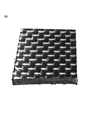
- FIG. 3 is a photograph of a CFRP plate before heat treatment.
- FIG. 4 is a photograph of the CFRP plate after undergoing the treatment according to Example 1-4.
- FIG. 5 is a photograph of the CFRP plate after undergoing the treatment according to Comparative Example 1-2.
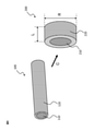
- FIG. 6 is a schematic view of the carbon fiber reinforced thermoplastic resin pellet according to the second invention of the present disclosure and the carbon fiber reinforced thermoplastic resin strand used in the process of manufacturing the pellet according to the second invention of the present disclosure. It is a schematic diagram.
- FIG. 7 is a schematic schematic diagram of a carbon fiber reinforced thermoplastic resin strand according to a third invention of the present disclosure.
- the method for decomposing a plastic-containing material according to the first invention of the present disclosure is as follows.
- the plastic-containing material is heated to the first surface temperature in the presence of the semiconductor material in an atmosphere in a heating furnace in which a low oxygen concentration gas having an oxygen concentration of less than 10% by volume is introduced, and the plastic in the plastic-containing material is heated.
- Disassembling including.
- FIG. 1 is a conceptual cross-sectional view for explaining the first disassembly method according to the present invention.
- the first decomposition mechanism of the plastic-containing material according to the present invention will be described below. There is no intention to limit the present invention by theory.
- the heat introduced for the decomposition of the plastic can be reduced as compared with the case where the semiconductor material is not used, and as a result, the energy consumption can be reduced.
- the inventors of the present invention can efficiently heat-treat the plastic while suppressing excessive oxidative heat generation by setting the oxygen concentration to a relatively low value even in the presence of the semiconductor material. I found out what I could do.
- the heat treatment is performed in the presence of the semiconductor material, good decomposition efficiency can be obtained even at a relatively low oxygen concentration, and oxygen in the heating furnace can be obtained.
- concentration By setting the concentration to a relatively low value, it is possible to suppress excessive oxidative heat generation and achieve a decomposition treatment with improved stability.
- FIG. 2 is a cross-sectional view schematically showing one embodiment of the decomposition method according to the first invention of the present disclosure.
- the heating furnace 20 shown in FIG. 2 has a heat source (heater) 23, a gas supply unit 24, an exhaust port 25, and an internal space 26.
- a porous carrier 21 is arranged in the internal space 26 of the heating furnace 20, and a semiconductor material is supported on the surface of the carrier 21.
- the plastic-containing material 22 is placed in contact with the carrier 21.
- the temperature of the atmosphere of the internal space 26 of the heating furnace 20 can be controlled via the heat source (heater) 23 of the heating furnace 20 so that the surface temperature of the plastic-containing material 22 becomes a specific temperature. ..
- the surface temperature of the plastic-containing material 22 can be measured via a temperature sensor 27 arranged within 5 mm from the surface of the plastic-containing material 22.
- a low oxygen concentration gas having an oxygen concentration of less than 10% by volume is introduced into the internal space 26 of the heating furnace 20 through the gas supply unit 24.
- the introduction rate of the low oxygen concentration gas according to the capacity in the furnace, the oxygen concentration in the atmosphere in the heating furnace 20 can be controlled.
- the low oxygen concentration gas can be pushed into the heating furnace through, for example, a gas supply unit provided in the heating furnace, or is sucked into the heating furnace by applying suction pressure to the exhaust port 25. Can be done.
- the low oxygen concentration gas is, for example, a mixed gas of air and nitrogen gas. By selecting the ratio of air and nitrogen gas, the oxygen concentration in the heating furnace can be controlled.
- the plastic-containing material is heated to a first surface temperature, for example, a first surface temperature of 300 ° C to 600 ° C, in an atmosphere in which the oxygen concentration is controlled to less than 10% by volume by introducing a low oxygen concentration gas.
- a first surface temperature for example, a first surface temperature of 300 ° C to 600 ° C
- the oxygen concentration is controlled to less than 10% by volume by introducing a low oxygen concentration gas.
- the plastic contained in the plastic-containing material 22 is decomposed into decomposition gases such as steam, carbon dioxide, and methane, and the decomposition gas is discharged from the exhaust port 25 of the heating furnace 20.
- the inorganic material contained in the plastic-containing material can be recovered after the heat treatment.
- the plastic-containing material contains plastic.
- the plastic-containing material may be a plastic material or a plastic composite material.
- plastic contained in the plastic-containing material examples include a thermoplastic resin and a thermosetting resin.
- thermoplastic resin contained in the plastic-containing material examples include polycarbonate (PC) resin, polyethylene (PE) resin, polypropylene (PP) resin, polyvinyl chloride (PVC) resin, polystyrene (PS) resin, and polyethylene terephthalate ( PET) resin, acrylonitrile-butadiene-styrene (ABS) resin, polyamide (PA) resin, polylactic acid (PLA) resin, polyimide (PI) resin, polymethylmethacrylate (PMMA) resin, methacrylic resin, polyvinyl alcohol (PVA) resin , Polyacetal resin, petroleum resin, AS resin, modified polyphenylene ether resin, polybutylene terephthalate (PBT) resin, polybutene (PB) resin, fluororesin, polyacrylate resin, polyether ether ketone (PEEK) resin, polyphenylene sulfide (PPS) Resin is mentioned.
- PC polycarbonate
- PE polyethylene
- PP polypropylene
- thermosetting resin contained in the plastic-containing material examples include phenol resin, urethane foam resin, polyurethane resin, urea resin, epoxy resin, unsaturated polyester resin, melamine resin, alkyd resin, vinyl ester resin, and cyanate resin. Can be mentioned.
- the plastic-containing material can contain at least one selected from the group consisting of the above-mentioned thermoplastic resin and thermosetting resin.
- the plastic-containing material is, in particular, a plastic composite material.
- the plastic composite material is, for example, fiber reinforced plastic (FRP).
- FRP fiber reinforced plastic
- Examples of the reinforcing fiber contained in the fiber-reinforced plastic include glass fiber (glass fiber), aramid fiber, and carbon fiber (carbon fiber).
- Carbon fiber reinforced plastic Plastic composites are, in particular, carbon fiber-containing plastic products such as carbon fiber reinforced plastics (CFRP). Carbon fiber reinforced plastic contains plastic and carbon fiber (carbon fiber material). The carbon fiber reinforced plastic may contain other members and / or materials (for example, reinforced fibers other than carbon fibers, resin molded products, metals, ceramics, etc.).
- the carbon fiber is not particularly limited, and examples thereof include PAN-based carbon fiber and pitch-based carbon fiber.
- the carbon fiber may be one kind or may be composed of two or more kinds.
- the carbon fiber contained in the carbon fiber reinforced plastic may be in any form, and may be, for example, a carbon fiber bundle, a woven fabric formed from the carbon fiber bundle, or a carbon fiber non-woven fabric.
- a low oxygen concentration gas having an oxygen concentration of less than 10% by volume is introduced into the atmosphere of the heating furnace.
- the oxygen concentration of the low oxygen concentration gas introduced into the atmosphere of the heating furnace is more than 0% by volume, 1% by volume or more, 2% by volume or more, 3% by volume or more, or 4% by volume or more, and / or. , 9% by volume or less, 8% by volume or less, or 7% by volume or less.
- the timing of introducing the low oxygen concentration gas into the heating furnace can be determined according to the type of plastic contained in the plastic-containing material, the surface temperature at which the decomposition of the plastic starts, and the like. Further, the timing of introducing the low oxygen concentration gas into the heating furnace can be determined based on the data acquired in advance regarding the self-heating of the plastic-containing material.
- a low oxygen concentration gas is applied to the atmosphere of the heating furnace while the surface temperature of the plastic-containing material held in the heating furnace is less than 300 ° C. Introduce inside.
- the oxygen concentration in the atmosphere of the heating furnace is less than 10% by volume while the surface temperature of the plastic-containing material held in the heating furnace is 250 ° C. or lower, 200 ° C. or lower, or 150 ° C. or lower. Introduce a certain low oxygen concentration gas.
- the lower limit of the surface temperature of the plastic-containing material held in the heating furnace when introducing a low oxygen concentration gas having an oxygen concentration of less than 10% by volume into the atmosphere of the heating furnace is not particularly limited, but for example. , 0 ° C or higher, 10 ° C or higher, 20 ° C or higher, or room temperature or higher.
- a low oxygen concentration gas having an oxygen concentration of less than 10% by volume is introduced into the atmosphere of the heating furnace, particularly in the atmosphere of the heating furnace holding a plastic-containing material having a surface temperature of less than 300 ° C. Introduced, thereby reducing the oxygen concentration of the atmosphere in the heating furnace to less than 10% by volume.
- a low oxygen concentration gas having an oxygen concentration of less than 10% by volume is introduced into the atmosphere of the heating furnace, particularly in the atmosphere of the heating furnace holding a plastic-containing material having a surface temperature of less than 300 ° C.
- the oxygen concentration in the atmosphere in the heating furnace is increased to more than 0% by volume, 1% by volume or more, 2% by volume or more, 3% by volume or more, or 4% by volume or more, and / or 9% by volume.
- control is performed to 8% by volume or less, or 7% by volume or less.
- the oxygen concentration in the heating furnace can be measured directly with an oxygen concentration meter (oxygen monitor), or can be determined based on the volume inside the furnace and the amount of gas introduced into the furnace.
- the oxygen concentration in the heating furnace is preferably the average oxygen concentration during the heat treatment.
- the introduction of the low oxygen concentration gas into the furnace can be performed, for example, by pushing the low oxygen concentration gas into the furnace through a gas supply unit provided in the heating furnace, or suction provided in the furnace. It can be done by sucking from the port (or exhaust port) so that the gas flows into the furnace from the gas supply unit provided at a place different from the suction port.
- the gas supply unit of the heating furnace may have, for example, an opening and / or may have a gas permeable material.
- the amount of gas introduced into the furnace can be set according to the capacity of the heating furnace, the desired oxygen concentration, etc., based on the unit resin amount of the resin to be decomposed (for example, epoxy resin).
- the amount of gas introduced into the furnace per unit amount of resin is determined in the range of 1 to 1000 (L / min) / kg or less, preferably in the range of 2 to 700 (L / min) / kg or less. Can be done.
- the time for replacing the atmosphere in the furnace with the introduced gas can be determined based on the determined gas introduction amount and the volume of the heating furnace used.
- the introduction amount of the low oxygen concentration gas is set with respect to the capacity in the furnace, whereby the atmosphere in the heating furnace is changed while the surface temperature of the plastic-containing material held in the heating furnace is less than 300 ° C. , Can be substituted by the introduced hypoxic gas.
- the low oxygen concentration gas introduced into the heating furnace can contain a diluting gas, and in particular, it is a mixed gas of air and the diluting gas.
- the diluting gas include nitrogen gas, carbon dioxide gas, steam, and superheated steam.
- the superheated steam is steam heated to a temperature equal to or higher than the boiling point. Superheated steam has the advantage of having a relatively high heat transfer property to the object to be decomposed.
- the heating furnace may be a combustion furnace or an electric furnace.
- the heating furnace is, for example, an internal space for accommodating a plastic-containing material and a semiconductor material, a heat source (heater) for heating the atmosphere in the heating furnace, and a gas supply for introducing a low oxygen concentration gas into the heating furnace. It can have a section, an exhaust port for discharging the decomposed gas, and optionally, a suction port for applying suction pressure to the inside of the heating furnace. It should be noted that one structure can also be used as an exhaust port and a suction port. As the exhaust port and / or the suction port, for example, one or more openings provided in the heating furnace can be used.
- the "surface temperature" of the plastic-containing material can be determined by measuring the temperature within 5 mm of the circumference of the plastic-containing material during the heat treatment.
- the surface temperature of the plastic-containing material can be controlled, for example, by controlling the temperature in the heating furnace via the heat source of the heating furnace, and / or introducing a low temperature gas into the heating furnace, and / Alternatively, it can be controlled by lowering the oxygen concentration and suppressing the heat generation of oxidation.
- the surface temperature of the plastic-containing material is measured via a temperature sensor located within 5 mm from the surface of the plastic-containing material, and this measured value is fed back to the heat source of the heating furnace to further increase the accuracy and surface temperature. It can also be controlled.
- data on the correlation between the temperature in the heating furnace and / or the output of the heat source and the surface temperature measured by the sensor may be acquired in advance, and the heat treatment may be performed based on this data. ..
- the method according to the first invention of the present disclosure The plastic-containing material is heated to the first surface temperature in the presence of the semiconductor material in an atmosphere in a heating furnace in which a low oxygen concentration gas having an oxygen concentration of less than 10% by volume is introduced, and the plastic in the plastic-containing material is heated. Disassembling, including.
- this heat treatment is carried out in an atmosphere where the oxygen concentration is less than 10% by volume due to the introduction of a low oxygen concentration gas having an oxygen concentration of less than 10% by volume, and in particular, more than 0% by volume and 1 Performed under an oxygen concentration of 9% by volume or more, 2% by volume or more, 3% by volume or more, or 4% by volume or more, and / or under an oxygen concentration of 9% by volume or less, 8% by volume or less, or 7% by volume or less. conduct.
- the “first surface temperature” is the surface temperature of the plastic-containing material.
- the “first surface temperature” can be determined by measuring the temperature within 5 mm around the plastic-containing material being heat-treated, similarly to the above-mentioned "surface temperature”.
- the first surface temperature may be 300 ° C. or higher, 325 ° C. or higher, or 350 ° C. or higher, and / or 600 ° C. or lower, 550 ° C. or lower, 500 ° C. or lower, or 450 ° C. or lower.
- the first surface temperature is, for example, 300 ° C. to 600 ° C., 300 ° C. to 550 ° C., 300 ° C. to 500 ° C., or 300 ° C. to 450 ° C.
- the plastic may not decompose. Further, when the first surface temperature exceeds the above range, when the plastic-containing material contains valuable resources such as carbon fibers, the valuable resources such as carbon fibers are deteriorated and / or burned down due to heating in the presence of oxygen. May be noticeable.
- the first surface temperature By setting the first surface temperature to a relatively low temperature, the effect of suppressing excessive oxidative heat generation is further enhanced.
- the first surface temperature is set to a temperature of 450 ° C. or higher during the heat treatment at an oxygen concentration of less than 10% by volume.
- the heating temperature is relatively low, the carbides formed on the surface of the plastic-containing material may suppress further decomposition of the plastic, but by setting the surface temperature to a temperature of 450 ° C or higher, the oxygen concentration is relatively relatively low. Carbide can be removed even if the temperature is low. Therefore, it is possible to further improve the decomposition efficiency of the plastic.
- the heat treatment is performed over a predetermined time under the introduction of a low oxygen concentration gas having an oxygen concentration of less than 10% by volume.
- This predetermined time may be 1 minute to 600 minutes, preferably 30 minutes to 300 minutes, and more preferably 60 minutes to 180 minutes.
- the time when the temperature of the heating furnace reaches 300 ° C. or the time when the start of decomposition of the plastic is confirmed can be set as the starting point of the above-mentioned "predetermined time".
- the semiconductor material may be placed in the heating furnace together with the plastic-containing material, or the semiconductor material may be placed in the heating furnace in advance, and then the plastic-containing material may be placed adjacent to or in contact with the semiconductor material. And may be arranged.
- the plastic-containing material and the semiconductor material to be heat-treated are arranged apart from each other at a distance of 50 mm or less.
- spacers placed between the plastic-containing material and the semiconductor material can be used.
- the lower limit of the distance is not particularly limited, but may be more than 0 mm, more than 1 mm, more than 5 mm, or more than 10 mm.
- the distance between the plastic-containing material and the semiconductor material can be measured at the place where they are closest to each other.
- the plastic-containing material and the semiconductor material to be heat-treated are arranged in contact with each other.
- the mode of contact between the plastic-containing material and the semiconductor material is not particularly limited.
- the two can be brought into contact with each other.
- the plastic-containing material may be placed on the semiconductor material supported on the surface of the carrier.
- the two can be brought into contact with each other by surrounding or covering at least a part or the whole of the plastic-containing material with the semiconductor material.
- the semiconductor material is not particularly limited as long as it is stable at the temperature and oxygen concentration of the present invention.
- the semiconductor material contains, for example, at least one selected from the group consisting of the following substances: BeO, MgO, CaO, SrO, BaO, CeO 2 , ThO 2 , UO 3 , U 3 O 8 , TIO 2 , ZrO 2 , V 2 O 5 , Y 2 O 3 , Y 2 O 2 S, Nb 2 O 5 , Ta 2 O 5 , MoO 3 , WO 3 , MnO 2 , Fe 2 O 3 , MgFe 2 O 4 , NiFe 2 O 4 , ZnFe 2 O 4 , ZnCo 2 O 4 , ZnO, CdO, Al 2 O 3 , MgAl 2 O 4 , ZnAl 2 O 4 , Tl 2 O 3 , In 2 O 3 , SiO 2 , SnO 2 , PbO 2 , UO 2 , Cr
- the semiconductor material is an oxide semiconductor material.
- oxide semiconductor materials include chromium oxide, titanium oxide, zinc oxide, vanadium oxide, tungsten oxide, molybdenum oxide, cobalt oxide, iron oxide, and copper oxide.
- the form of the semiconductor material is not particularly limited, and may be, for example, a plate shape, a granular shape, or a honeycomb shape. From the viewpoint of accelerating the decomposition of the plastic, it is preferable that the semiconductor material is supported on the surface of the carrier having breathability.
- the carrier having breathability may be a porous body made of ceramics or the like, a honeycomb-shaped support, or the like.
- the semiconductor material may be a sintered body of a semiconductor.
- the heat treatment method according to one preferred embodiment of the first invention according to the present disclosure is To heat the plastic-containing material subjected to the heat treatment at the first surface temperature in the presence of a semiconductor material in an atmosphere having an oxygen concentration of 10% by volume or more. including.
- the heat treatment at an oxygen concentration of 10% by volume or more is preferably carried out under an oxygen concentration of more than 10% by volume, 12% by volume or more, 15% by volume or more, or 20% by volume or more, and / or 30% by volume. It is carried out below or at an oxygen concentration of 25% by volume or less.
- the plastic-containing material heat-treated at a relatively low oxygen concentration is further heat-treated under an increased oxygen concentration.
- the heat treatment with the introduction of a low oxygen concentration gas having an oxygen concentration of less than 10% by volume and the heat treatment with an oxygen concentration of 10% by volume or more can be continuously performed in the same heating furnace. That is, for example, after heating the plastic-containing material to the first surface temperature, the oxygen concentration can be increased to 10% by volume or more in the same heating furnace, and further heat treatment can be performed.
- the conventional plastic decomposition method it is necessary to perform processing such as shredding of the object to be processed after batch processing, but heat treatment under the introduction of a low oxygen concentration gas having an oxygen concentration of less than 10% by volume and oxygen.
- An atmosphere having an oxygen concentration of 10% by volume or more can be formed, for example, by introducing a high oxygen concentration gas having an oxygen concentration of 10% by volume or more into the heating furnace, and in particular, air and / or oxygen gas in the heating furnace. Can be formed by introducing.
- the oxygen concentration of the high oxygen concentration gas may be more than 10% by volume, 12% by volume or more, 15% by volume or more, or 20% by volume or more, and / or 30% by volume or less, or 25% by volume or less. It's okay.
- the semiconductor material used in the heat treatment at the first surface temperature can be used.
- the plastic-containing material subjected to the heat treatment at the first surface temperature is heated to the second surface temperature in the presence of the semiconductor material in an atmosphere having an oxygen concentration of 10% by volume or more.
- the “second surface temperature” is the surface temperature of the plastic-containing material to be treated.
- the “second surface temperature” can be determined by measuring the temperature within 5 mm around the plastic-containing material being heat-treated, similarly to the above-mentioned “surface temperature” and "first surface temperature”.
- the second surface temperature may be in the range of 400 ° C to 600 ° C. More preferably, the second surface temperature is 425 ° C to 575 ° C, or 450 ° C to 550 ° C.
- the decomposition efficiency may not be improved. Further, when the second surface temperature exceeds the above range, when the plastic-containing material contains valuable resources such as carbon fibers, the valuable resources such as carbon fibers are deteriorated and / or burned down due to heating in the presence of oxygen. May be noticeable.
- the second surface temperature may be substantially the same as the first surface temperature.
- the second surface temperature may be equal to or higher than the first surface temperature, or is at least 5 ° C, at least 10 ° C, at least 25 ° C, at least 50 ° C, or at least 75 ° C higher than the first surface temperature. good.
- the upper limit of the difference between the first surface temperature and the second surface temperature is not particularly limited, but may be, for example, 200 ° C. or lower, or 100 ° C. or lower.
- the heat treatment with an oxygen concentration of 10% by volume or more can be performed over a predetermined time.
- This predetermined time may be, for example, 1 minute to 600 minutes, 60 minutes to 360 minutes, or 90 minutes to 300 minutes.
- ⁇ Use> According to the method for decomposing a plastic-containing material according to the first invention of the present disclosure, a wide range of plastics can be efficiently vaporized and decomposed. Further, the decomposition method according to the first invention of the present disclosure can be applied to volatile organic compounds (VOC), flue gas, particulate matter (PM) and the like, and can also be used for exhaust gas treatment.
- VOC volatile organic compounds
- PM particulate matter
- the first invention of the present disclosure also relates to a method for recovering an inorganic material contained in a plastic composite material.
- the plastic-containing material which is a plastic composite material, contains a plastic and an inorganic material
- this recovery method is: Disassembling the plastic in the plastic-containing material by the decomposition method according to the first aspect of the present disclosure to recover the inorganic material.
- the above description regarding the decomposition method of the plastic-containing material can be referred to.
- the plastic can be efficiently decomposed. Therefore, according to the recovery method according to the first invention of the present disclosure, the plastic contained in the plastic composite material can be efficiently and selectively decomposed, so that the inorganic material having good physical properties can be efficiently decomposed. Can be collected in.
- the inorganic material can be recovered without crushing the plastic composite material. It should be noted that crushing the plastic composite material is not particularly excluded, and crushing can be performed arbitrarily.
- the plastic-containing material as a plastic composite material is subjected to two-step heating. That is, the plastic is decomposed by subjecting the plastic composite material to heating under the introduction of a low oxygen concentration gas (oxygen concentration less than 10%) and subsequent heat treatment at an oxygen concentration of 10% by volume or more. And recover the inorganic material.
- a low oxygen concentration gas oxygen concentration less than 10%
- the plastic composite material When recovering an inorganic material, it is desirable to suppress deterioration of the physical properties of the inorganic material due to excessive oxidative heat generation, and further, it is desirable to suppress deterioration of the physical properties of the inorganic material due to carbonization of the plastic and adhesion to the inorganic material and remaining. Is preferable.
- the physical properties of the inorganic material deteriorate due to the excessive heat generation of oxidation because the oxygen concentration is relatively low at the initial stage where excessive heat generation of oxidation is likely to occur. It is suppressed.
- the heat treatment is performed after that, the oxygen concentration is increased, so that the carbonized resin remaining on the inorganic material can be efficiently removed. As a result, even better physical properties of the recovered inorganic material can be ensured by the method of recovering the inorganic material through the two-step heat treatment.
- plastic composite materials containing inorganic materials and plastics include fiber reinforced plastics (FRP), particularly carbon fiber reinforced plastics.
- FRP fiber reinforced plastics
- the inorganic material examples include inorganic fibers, for example, alumina fibers, ceramic fibers, silica fibers and the like.
- the inorganic fiber is, in particular, carbon fiber (carbon fiber material).
- the carbon fiber is not particularly limited, and examples thereof include PAN-based carbon fiber and pitch-based carbon fiber.
- the carbon fiber may be one kind or may be composed of two or more kinds.
- the carbon fiber may be in any form, and may be, for example, a carbon fiber bundle, a woven fabric formed from the carbon fiber bundle, or a non-woven carbon fiber.
- the residual carbon derived from the plastic recovered together with the inorganic material is reduced, and in particular, the residual carbon is recovered from the inorganic material. It is 5% by weight or less.
- the residual carbon is 4% by weight or less, 3% by weight or less, 2% by weight or less, 1% by weight or less, 0.9% by weight or less, 0.5% by weight or less, or It is 0.1% by weight or less. It is preferable that the residual carbon is reduced as much as possible, but the lower limit thereof may be 0.001% by weight or more.
- the amount of the residual carbon in the recovered inorganic material can be measured in the same manner as the amount of the residual carbon in the regenerated carbon fiber described later.
- the recovery method according to the first invention of the present disclosure it is possible to recover carbon fiber having better physical properties than the carbon fiber before manufacturing the carbon fiber reinforced plastic.
- carbon fiber having a single fiber tensile strength of 3.0 GPa or more and a wibble shape coefficient of 6.0 or more can be obtained as an inorganic material from carbon fiber reinforced plastic. Obtainable.
- the single fiber tensile strength is preferably 3.1 GPa or more, 3.2 GPa or more, 3.3 GPa or more, or 3.4 GPa or more.
- the upper limit of the tensile strength of the single fiber is not particularly limited, but may be 6.0 GPa or less.
- Single fiber tensile strength can be measured according to JIS R7606 as follows: At least 30 single fibers are collected from the fiber bundle and The diameter of the single fiber is measured in the side image of the single fiber taken with a digital microscope, and the cross-sectional area is calculated. The sampled single fiber is fixed to the perforated mount with an adhesive, and A mount on which a single fiber was fixed was attached to a tensile tester, and a tensile test was performed at a test length of 10 mm and a strain rate of 1 mm / min to measure the tensile breaking stress. The tensile strength is calculated from the cross-sectional area of the single fiber and the tensile breaking stress. The average of the tensile strengths of at least 30 single fibers is defined as the single fiber tensile strength.
- the Weibull shape coefficient is preferably 6.5 or more, 7.0 or more, 7.5 or more, 8.0 or more, or 8.5 or more.
- the upper limit of the Weibull shape coefficient is not particularly limited, but may be 15.0 or less.
- the high Weibull shape coefficient of the single fiber tensile strength means that the variation in the single fiber tensile strength is small.
- F is the fracture probability obtained by the symmetric sample cumulative distribution method
- ⁇ is the single fiber tensile strength (MPa)
- m is the Weibull shape coefficient
- C is a constant.
- Weibull plotting with lnln ⁇ 1 / (1-F) ⁇ and ln ⁇ can be performed, and the Weibull shape coefficient m can be obtained from the slope that is first-order approximated.
- the metal material is recovered from the plastic-containing material containing the plastic and the metal material.
- a method for recovering a metallic material including the following:
- the plastic-containing material contains the plastic and the metal material, and the plastic in the plastic-containing material is decomposed by the decomposition method according to the first aspect of the present disclosure to recover the metal material.
- metal materials include gold and rare metals.
- Examples of the metal material and the plastic composite material containing plastic include a composite material having a metal material contained in a matrix resin, and in particular, a solar cell panel, an electronic component, and an electronic circuit.
- the regenerated carbon fiber (regenerated carbon fiber material) according to the first invention of the present disclosure can be produced by recovering carbon fiber from carbon fiber reinforced plastic.
- the regenerated carbon fiber can have better physical properties than the carbon fiber before producing the carbon fiber reinforced plastic.
- the method for producing recycled carbon fiber is not particularly limited.
- the regenerated carbon fiber can be produced by recovering the regenerated carbon fiber from the carbon fiber reinforced plastic by the recovery method according to the first invention of the present disclosure.
- the regenerated carbon fiber has a single fiber tensile strength of 3.0 GPa or higher and a Weibull shape coefficient of 6.0 or higher.
- the single fiber tensile strength and the Weibull shape coefficient can be measured and determined by the methods described above.
- the single fiber tensile strength of the regenerated carbon fiber is preferably 3.1 GPa or more, 3.2 GPa or more, 3.3 GPa or more, or 3.4 GPa or more.
- the upper limit of the tensile strength of the single fiber is not particularly limited, but may be 6.0 GPa or less.
- the Weibull shape coefficient of the regenerated carbon fiber is preferably 6.5 or more, 7.0 or more, 7.5 or more, 8.0 or more, or 8.5 or more.
- the upper limit of the Weibull shape coefficient is not particularly limited, but may be 15.0 or less.
- a method for producing a regenerated carbon fiber having a single fiber tensile strength of 3.0 GPa or more and a Weibull shape coefficient of 6.0 or more is available.
- the plastic-containing material is heated to the first surface temperature in the presence of the semiconductor material in an atmosphere in a heating furnace into which a low oxygen concentration gas having an oxygen concentration of less than 10% by volume is introduced, and the plastic in the plastic-containing material is heated.
- the plastic-containing material is carbon fiber reinforced plastic containing carbon fiber.
- a method for producing a regenerated carbon fiber having a single fiber tensile strength of 3.0 GPa or more and a Weibull shape coefficient of 6.0 or more is used.
- the plastic-containing material is heated to the first surface temperature in the presence of the semiconductor material in an atmosphere in a heating furnace into which a low oxygen concentration gas having an oxygen concentration of less than 10% by volume is introduced, and the first surface temperature is concerned.
- the plastic in the plastic-containing material is decomposed.
- the plastic-containing material is carbon fiber reinforced plastic containing carbon fiber.
- a low oxygen concentration gas having an oxygen concentration of less than 10% by volume is used while the surface temperature of the plastic-containing material is less than 300 ° C. Introduce into the atmosphere of the heating furnace.
- the amount of residual carbon is reduced, and in particular, the residual carbon is 5% by weight or less with respect to the regenerated carbon fiber.
- the residual carbon is 4% by weight or less, 3% by weight or less, 2% by weight or less, 1% by weight or less, 0.9% by weight or less, 0.5% by weight or less, based on the regenerated carbon fiber. Or 0.1% by weight or less.
- the amount of residual carbon is preferably reduced as much as possible, and the lower limit thereof is not particularly limited, but may be, for example, 0.01% by weight or more with respect to the regenerated carbon fiber.
- residual carbon is a carbonized component derived from the plastic contained in the carbon fiber reinforced plastic which is a raw material for producing recycled carbon fiber.
- the amount of residual carbon (residual carbon component) in the regenerated carbon fiber can be determined by thermogravimetric analysis (TGA).
- thermogravimetric analysis can be performed by the following procedure: (I) An air supply rate of 0.2 L / min, a heating rate of 5 ° C./min, and 1/1 in a thermogravimetric analyzer for 1 to 4 mg of a sample piece obtained by crushing recycled carbon fiber. At a recording speed of 6s, Temperature rise from room temperature to 100 ° C, Holding at 100 ° C for 30 minutes, Temperature rise from 100 ° C to 400 ° C, and It has a process of holding at 400 ° C and performs thermogravimetric analysis for a total of 300 minutes.
- thermogravimetric analysis with retention at 400 ° C. for 480 minutes may be performed instead of a total of 300 minutes of thermogravimetric analysis. Further, instead of holding at 400 ° C. for 480 minutes, it may be held at a specific temperature within the range of more than 400 ° C. and 500 ° C. or lower for 480 minutes.
- the above measurement can be performed after removing the resin.
- the plastic-containing material is heated to the first surface temperature in the presence of the semiconductor material in an atmosphere in a heating furnace into which a low oxygen concentration gas having an oxygen concentration of less than 10% by volume is introduced, and the plastic in the plastic-containing material is heated.
- the plastic-containing material is carbon fiber reinforced plastic containing carbon fiber.
- the plastic-containing material is heated to the first surface temperature in the presence of the semiconductor material in an atmosphere in a heating furnace into which a low oxygen concentration gas having an oxygen concentration of less than 10% by volume is introduced, and the first surface temperature is concerned.
- the plastic in the plastic-containing material is decomposed.
- the plastic-containing material is carbon fiber reinforced plastic containing carbon fiber.
- the second invention of the present disclosure relates to a blended yarn of regenerated carbon fiber and a thermoplastic resin fiber, and a carbon fiber reinforced thermoplastic resin pellet formed from the blended yarn.
- the second invention of the present disclosure relates to a method for producing them.
- the blended yarn of the regenerated carbon fiber and the thermoplastic resin fiber according to the second invention of the present disclosure is
- the regenerated carbon fiber has a single fiber tensile strength of 3.0 GPa or more and a wibble shape coefficient of 6.0 or more, and the regenerated carbon fiber contains a residual carbon component, and the content of the residual carbon component is the regenerated carbon fiber. It should be more than 0% by weight and less than 5.0% by weight. It is characterized by.
- the blended yarn according to the second invention of the present disclosure can be produced by a general spinning method.
- This spinning method may include each step of cotton carding, kneading, and rough spinning.
- the cotton carding step may be a step of separating and unraveling an aggregate of each discontinuous fiber, opening the fiber, and orienting the mixed single fibers in one direction to produce a thick sliver
- the kneading step may be a step.
- the sliver may be a step of combining several slivers and further improving the fiber orientation while stretching the sliver
- the roving step may be a step of winding the blended yarn by further stretching and twisting the sliver.
- each fiber Since the tensile strength of the sliver is given by the frictional force due to the contact or entanglement of the single fibers, each fiber is satisfactorily opened, and the contact area or entanglement between the single fibers is increased to improve the tensile strength. It is possible to suppress a decrease in tensile strength by suppressing single fiber breakage and not increasing the number of joints between single fibers. By strengthening the twist, the contact area between the single fibers increases, so that the tensile strength is improved. Oil may be applied to each fiber or sliver as needed to supplement the frictional force.
- carbon fibers have no crimping property and high surface smoothness, so that the entanglement between single fibers is weak, and further, they have a high elastic modulus and low elongation and are hard, so that they are relatively easy to break and break. ..
- the thermoplastic resin fiber blended with the regenerated carbon fiber has an effect of enhancing the entanglement between the single fibers, and even if a small amount of the thermoplastic resin fiber is blended, the tensile strength of the sliver is greatly improved.
- the blended yarn according to the second invention of the present disclosure has a high wibble shape coefficient in the single fiber tensile strength of the regenerated carbon fiber, so that the variation in tensile strength is small and the same tensile strength is obtained. It is considered that the single fiber breakage of the regenerated carbon fiber is relatively suppressed because the number of single fibers having low tensile strength is relatively small as compared with the general unused carbon fibers having.
- the general characteristics of the regenerated carbon fiber obtained by the method of heat treatment and decomposition are that the tensile strength tends to decrease due to the formation of oxidation defects in the regenerated carbon fiber, and the carbon dioxide of the resin component is used as the residual carbon component. May be contained in recycled carbon fiber.
- the residual carbon component may firmly bind the single fibers of the regenerated carbon fiber to each other. In the production of spun yarn, the residual carbon component is considered to prevent the opening of fibers in the cotton carding process and the entanglement of single fibers.
- the blended yarn according to the second invention of the present disclosure uses recycled carbon fiber having a relatively low content of residual carbon component as a raw material, so that entanglement between single fibers can be obtained. easy.
- the blended yarn according to the second invention of the present disclosure is stably manufactured without causing yarn pull-out due to the tension of the spinning process because the frictional force due to the entanglement of the single fibers is easily obtained. It is considered that the tensile strength for this is easy to obtain.
- the second invention of the present disclosure also includes carbon fiber reinforced thermoplastic resin pellets having the above-mentioned blended yarn.
- This carbon fiber reinforced thermoplastic resin pellet is Having a core sheath structure,
- the blended yarn is the core component, and the thermoplastic resin is the sheath component. It is characterized by.
- the carbon fiber reinforced thermoplastic resin pellet according to the second invention of the present disclosure is a general long fiber reinforced pellet except that the blended yarn according to the second invention of the present disclosure is used as a substitute for continuous carbon fiber. Since it can be manufactured by cutting the resin strands obtained by coating the blended yarn with a thermoplastic resin in the same manner as the manufacturing method, the resin strands in which discontinuous carbon fibers are kneaded and dispersed in the thermoplastic resin can be obtained. It can contain regenerated carbon fiber with a relatively long fiber length as compared to the short fiber reinforced pellets produced by cutting. That is, the carbon fiber reinforced thermoplastic resin pellet according to the second invention of the present disclosure can be supplied to an injection molding machine or the like to produce a carbon fiber-containing product having excellent mechanical properties and the like.
- the recycled carbon fiber contains a carbon fiber component and a carbon component other than the carbon fiber component (particularly, a residual carbon component).
- the carbon component other than the carbon fiber component is attached to the surface of the carbon fiber component.
- the regenerated carbon fiber according to the second invention of the present disclosure has a single fiber tensile strength of 3.0 GPa or more and a wible shape coefficient of 6.0 or more, and also contains a residual carbon component, and the residual carbon component is contained.
- the amount is more than 0% by weight and 5.0% by weight or less with respect to the regenerated carbon fiber.
- the regenerating method is not particularly limited, and for example, it may be a regenerated carbon fiber obtained by heat-treating a carbon fiber-containing plastic product such as carbon fiber reinforced plastic (CFRP). ..
- the regenerated carbon fiber is a regenerated carbon fiber obtained by a semiconductor thermoactive method. That is, a particularly preferable embodiment of the present disclosure includes regenerated carbon fibers produced by decomposing a plastic component contained in a carbon fiber-containing plastic product by a semiconductor thermoactive method.
- the "semiconductor thermal activation method” is a method of decomposing a compound to be decomposed such as a polymer by utilizing the thermal activity of a semiconductor (Thermal Activation of Semi-conductors, TASC).
- the above description regarding the first invention can be referred to. That is, the second invention of the present disclosure (and the third and third below) by recovering the carbon fiber from the plastic-containing material containing the plastic and the carbon fiber by using the above-mentioned decomposition method according to the first invention.
- a regenerated carbon fiber having the characteristics according to the fourth invention can be obtained.
- the single fiber tensile strength is preferably 3.1 GPa or more, 3.2 GPa or more, 3.3 GPa or more, or 3.4 GPa or more.
- the upper limit of the tensile strength of the single fiber is not particularly limited, but may be 6.0 GPa or less.
- the single fiber tensile strength can be measured as described above with respect to the first invention in accordance with JIS R7606:
- the Weibull shape coefficient is preferably 6.5 or more, 7.0 or more, 7.5 or more, 8.0 or more, or 8.5 or more.
- the upper limit of the Weibull shape coefficient is not particularly limited, but may be 15.0 or less.
- the high Weibull shape coefficient of the single fiber tensile strength means that the variation in the single fiber tensile strength is small.
- the Weibull shape coefficient can be calculated as described above with respect to the first invention.
- the carbon fiber component in the regenerated carbon fiber is usually derived from the carbon fiber contained in the carbon fiber-containing product or the like which is the raw material of the regenerated carbon fiber.
- the carbon fiber component in the regenerated carbon fiber may be modified by undergoing heat treatment or the like in the process of producing the regenerated carbon fiber.
- the carbon fiber component in the regenerated carbon fiber may be, for example, a PAN-based carbon fiber or a pitch-based carbon fiber.
- the form of the carbon fiber component in the regenerated carbon fiber is not particularly limited, but may be the form of a carbon fiber bundle composed of a plurality of single yarns (single fibers, filaments).
- the number of filaments constituting the carbon fiber bundle may be in the range of 1,000 to 80,000 or 3,000 to 50,000.
- the diameter of the filament constituting the carbon fiber component in the regenerated carbon fiber may be 0.1 ⁇ m to 30 ⁇ m, 1 ⁇ m to 10 ⁇ m, or 3 ⁇ m to 8 ⁇ m.
- the residual carbon component contained in the regenerated carbon fiber is particularly the residual carbon derived from the resin contained in the carbon fiber-containing plastic product used as a raw material in producing the regenerated carbon fiber.
- the residual carbon component is more than 0% by weight and 5.0% by weight or less with respect to the regenerated carbon fiber. In this case, it is possible to obtain a blended yarn having improved yarn pull-out resistance to the tension of the spinning process.
- the residual carbon component is more than 0% by weight and 5.0% by weight or less, contamination due to a relatively large amount of carbon component (particularly charcoal) can be avoided, and the blended yarn is used as a material. It is possible to reduce the carbon component that can become a foreign substance when manufacturing a carbon fiber-containing product or the like.
- the residual carbon component is 4.0% by weight or less, 3.0% by weight or less, or 2.0% by weight or less with respect to the regenerated carbon fiber.
- the residual carbon component is preferably reduced as much as possible, but 0.01% by weight or more, 0.1% by weight or more, 0.2% by weight or more, 0.4% by weight or more, 0 with respect to the carbon fiber. It may be 6.6% by weight or more, 0.8% by weight or more, 1.0% by weight or more, or 1.2% by weight or more.
- the content of the residual carbon component in the regenerated carbon fiber can be measured by the thermogravimetric analysis method (TGA method) as described above with respect to the first invention.
- thermoplastic resin fibers contained in the blended yarn according to the second invention of the present disclosure include polyolefin resin fibers (for example, polypropylene resin fibers and polyethylene resin fibers), polyester resin fibers (for example, polyethylene terephthalate resin fibers, and polybutylene). (Telephthalate resin fiber and polylactic acid resin fiber), polyamide resin fiber, polyether ketone resin fiber, polycarbonate resin fiber, phenoxy resin fiber, and polyphenylene sulfide resin fiber.
- the thermoplastic resin fiber may be only one kind, or may be a mixture of two or more kinds of thermoplastic resin fibers.
- the second blended yarn according to the present invention is a spun yarn containing regenerated carbon fiber and thermoplastic resin fiber.
- the blended yarn may also include, for example, a binder applied to the regenerated carbon fiber.
- the blended yarn may be a spun yarn substantially composed of regenerated carbon fiber and thermoplastic resin fiber.
- the content of the regenerated carbon fiber contained in the blended yarn according to the second invention is preferably more than 50% by weight and 98% by weight or less with respect to the blended yarn. Particularly preferably, it may be more than 55% by weight, more than 60% by weight, more than 65% by weight, or more than 70% by weight, and / or 97% by weight or less, 96% by weight or less, 95% by weight or less, 94% by weight. % Or less, 93% by weight or less, 92% by weight or less, 91% by weight or less, or 90% by weight or less.
- the thermoplastic resin is used for the purpose of increasing the carbon fiber content when the carbon fiber reinforced thermoplastic resin pellets according to the present disclosure are produced using the regenerated carbon fiber. It is not necessary to reduce the amount of coating in the fiber, and the stability of the coating process is improved.
- the content of the regenerated carbon fiber is 98% by weight or less, the entanglement with the thermoplastic resin fiber to be blended becomes sufficient, and the yarn loss due to the tension in the spinning process is less likely to occur.
- the content of the thermoplastic resin fiber contained in the blended yarn according to the second invention may be 50% by weight or less, 40% by weight or less, or 30% by weight or less with respect to the blended yarn, and /. Alternatively, it may be more than 3% by weight, more than 4% by weight, more than 5% by weight, more than 6% by weight, more than 7% by weight, more than 8% by weight, more than 9% by weight, or more than 10% by weight.
- the regenerated carbon fiber contained in the blended yarn according to the second invention can have an average length of 20 mm or more and 80 mm or less. Fibers having a length in this range can be obtained, for example, by cutting fibers having a relatively long size.
- the average length of the regenerated carbon fiber may be 20 mm or more, 30 mm or more, or 40 mm or more, and / or 80 mm or less, 70 mm or less, or 60 mm or less.
- the thermoplastic resin fiber contained in the second blended yarn according to the present invention can have an average length of 20 mm or more and 80 mm or less. Fibers having a length in this range can be obtained, for example, by cutting fibers having a relatively long size.
- the average length of the thermoplastic resin fiber may be 20 mm or more, 30 mm or more, or 40 mm or more, and / or 80 mm or less, 70 mm or less, or 60 mm or less.
- the yarn pull-out resistance to the spinning process tension of the sliver can be improved.
- the average length of the regenerated carbon fiber and the thermoplastic resin fiber is 80 mm or less, it is possible to reduce the wrapping around the manufacturing equipment parts.
- the average lengths of the regenerated carbon fibers and the thermoplastic resin fibers are measured by measuring the lengths of 50 fibers visually with a nogis or the like, or in an image acquired with a digital camera or an optical microscope. It can be calculated by averaging the values.
- the blended yarn of the regenerated carbon fiber and the thermoplastic resin fiber according to the second invention of the present disclosure can be produced by a general spinning method. That is, in the method for producing a blended yarn according to the second invention of the present disclosure, an aggregate of discontinuous fibers is separated and opened, and the mixed single fibers are oriented in one direction to produce a thick sliver. It may include a cotton carding process, a kneading process in which several slivers are combined and stretched to further improve the degree of fiber orientation, and a crude spinning process in which the sliver is further stretched and twisted to wind up the blended yarn.
- a binder can be applied when producing the second blended yarn according to the present invention.
- the binder has, in particular, a role of promoting the binding of the regenerated carbon fiber to the thermoplastic resin fiber.
- the timing of applying the binder is not particularly limited, but it may be applied directly to the regenerated carbon fiber, or may be applied to a blended yarn containing the regenerated carbon fiber and the thermoplastic resin fiber.
- the binder may be, for example, an epoxy resin.
- the method of applying the binder is not particularly limited, and a known method can be used.
- the binder can be applied by immersing the regenerated carbon fiber or the blended yarn in a solution or dispersion of the binder and drying it. can.
- the amount of the binder may be 0.1% by weight to 25% by weight or 1% by weight to 20% by weight with respect to the regenerated carbon fiber.
- a carbon fiber reinforced thermoplastic resin pellet having a core-sheath structure which comprises a blended yarn according to the second invention of the present disclosure as a core component and a thermoplastic resin as a sheath component. .. Since the pellet according to the second invention of the present disclosure contains regenerated carbon fiber having a relatively long fiber length as compared with a short fiber reinforced pellet obtained by kneading and dispersing recycled carbon fiber in a thermoplastic resin, it is injected. By being supplied to a molding machine or the like, it is possible to manufacture a carbon fiber-containing product having excellent mechanical properties and the like.
- the carbon fiber reinforced thermoplastic resin pellet having a core-sheath structure according to the second invention of the present disclosure is to produce a carbon fiber reinforced thermoplastic resin strand by coating a blended yarn with a thermoplastic resin, and to obtain the strand. It can be produced by a method including cutting, and more specifically, as described above, except that the blended yarn according to the second invention of the present disclosure is used instead of the continuous carbon fiber, it is a general length. Similar to the method for producing fiber-reinforced pellets, it can be produced by cutting resin strands coated with a thermoplastic resin.
- the coating process in which the blended yarn that is continuously conveyed while being rewound is threaded through a die in which the thermoplastic resin melted from a supply port different from the blended yarn is continuously supplied, and the carbon fiber reinforcement discharged from the die. It can be manufactured by a method comprising a cutting step in which the thermoplastic resin strands are cut after being cooled.
- thermoplastic resin that is, the thermoplastic resin constituting the sheath component of the pellet
- the thermoplastic resin used for the coating treatment in the production of the pellet according to the second aspect of the present invention
- a polyolefin resin for example, polypropylene resin and polyethylene resin
- a polyester resin that is, a polyester resin
- polyamide resin, polyether ketone resin, polycarbonate resin, phenoxy resin, and polyphenylene sulfide resin can be mentioned.
- This thermoplastic resin may be only one kind, or may be a mixture of two or more kinds of thermoplastic resins.
- thermoplastic resin constituting the sheath component of the pellet according to the second invention may be of the same type as or different from the thermoplastic resin fiber contained in the blended yarn according to the second invention of the present disclosure. It may be a type.
- the melting point (T0 (° C.)) of the thermoplastic resin constituting the sheath component of the pellet is 10 (° C.) higher than the melting point (T1 (° C.)) of the thermoplastic resin fiber contained in the blended yarn according to the present disclosure. ) Very low is preferable. In this case, when the carbon fiber reinforced thermoplastic resin pellets according to the present disclosure are produced, the thermoplastic resin fibers contained in the blended yarn are suppressed from melting, and only the thermoplastic resin covering the blended yarn melts.
- T1-T0 The upper limit of the difference (T1-T0) between T1 and T0 is not particularly limited, but is, for example, 200 (° C.) or less, 150 (° C.) or less, 100 (° C.) or less, or 50 (° C.) or less. May be.
- thermoplastic resins used for the coating treatment include various types as long as the mechanical strength is not impaired for the purpose of improving fluidity, appearance gloss, flame retardant properties, thermal stability, weather resistance, impact resistance and the like.
- Polymers, fillers, stabilizers, pigments and the like may be blended.
- the carbon fiber reinforced thermoplastic resin pellet according to the second invention of the present disclosure cuts the carbon fiber reinforced thermoplastic resin strand obtained by coating the blended yarn according to the second invention of the present disclosure with a thermoplastic resin ( Since it is manufactured by slicing), the blended yarn is the core component and the thermoplastic resin is the sheath component.
- the thermoplastic resin as the sheath component is 50 weight by weight with respect to 100 parts by weight of the regenerated carbon fiber contained in the blended yarn.
- the amount is preferably from 100 parts by weight to 1000 parts by weight, more preferably from 100 parts by weight to 750 parts by weight, and most preferably from 250 parts by weight to 500 parts by weight.
- the cut length of the pellet according to the second invention is preferably 3 mm or more and 10 mm or less. Particularly preferably, it may be 5 mm or less.
- the cut length of the pellet corresponds, in particular, to the length of the core structure of the pellet in the axial direction.
- the cut length of the pellet is 3 mm or more, the average length of the regenerated carbon fiber becomes relatively long, so that the mechanical properties of the carbon fiber-containing product using the pellet as a molding raw material can be further improved.
- the cut length of the pellet is 10 mm or less, the regenerated carbon fiber is easily dispersed during the molding process, and the mechanical properties of the carbon fiber-containing product can be further improved.
- the diameter of the core-sheath type pellet is not particularly limited, but may be 1/10 or more and 2 times or less of the cut length of the pellet, and may be 1/4 or more and 1 time or less of the cut length of the pellet. preferable. If the diameter of the pellet is too small, some parts may not be covered. On the contrary, if the diameter of the pellet is too large, poor engagement with the molding machine may occur and molding may become difficult.
- the cut length and diameter of the pellets For the cut length and diameter of the pellets, measure the cut length or diameter of 30 or more pellets visually using a caliper or the like, or in an image acquired with a digital camera or an optical microscope, and average the measured values. By doing so, it can be calculated.
- FIG. 6 is a schematic view schematically showing a carbon fiber reinforced thermoplastic resin pellet 200 having a core-sheath structure according to the second invention of the present disclosure.
- the figure is a schematic diagram for illustration purposes and is not in scale.
- the pellet 200 having a core-sheath structure has a core component 210 and a sheath component 220. Further, the pellet 200 has a cut length L and a diameter R.
- the pellet 200 having a core-sheath structure cuts (cutting treatment, “C” in FIG. 6) a carbon fiber-reinforced thermoplastic resin strand 100 having a core-sheath structure having a core component 110 made of a blended yarn and a sheath component 120 made of a thermoplastic resin. ) Can be manufactured.
- the third invention of the present disclosure relates to a carbon fiber reinforced thermoplastic resin strand containing a blended yarn of regenerated carbon fiber and thermoplastic resin fiber, which is suitable for three-dimensional modeling.
- the third invention of the present disclosure relates to a method for producing them.
- the carbon fiber reinforced thermoplastic resin strand according to the third invention of the present disclosure has a blended yarn containing regenerated carbon fiber and thermoplastic resin fiber.
- This blended yarn of recycled carbon fiber and thermoplastic resin fiber is
- the regenerated carbon fiber has a single fiber tensile strength of 3.0 GPa or more and a wibble shape coefficient of 6.0 or more, and the regenerated carbon fiber contains a residual carbon component, and the content of the residual carbon component is the regenerated carbon. More than 0% by weight and less than 5.0% by weight with respect to the fiber, It is characterized by.
- the carbon fiber reinforced thermoplastic resin strand comprises the above-mentioned blended yarn.
- the blended yarn according to the third invention of the present disclosure is manufactured by a general spinning method, and may include each step of a cotton carding step, a kneading step, and a roving step. For each of these steps, the above description of the second invention can be referred to.
- each fiber Since the tensile strength of the sliver is given by the frictional force due to the contact or entanglement of the single fibers, each fiber is satisfactorily opened, and the contact area or entanglement between the single fibers is increased to improve the tensile strength. It is possible to suppress a decrease in tensile strength by suppressing single fiber breakage and not increasing the number of joints between single fibers. By strengthening the twist, the contact area between the single fibers increases, so that the tensile strength is improved. In order to supplement the frictional force, oil may be applied to each fiber or sliver as needed.
- carbon fibers have no crimping property and high surface smoothness, so that the entanglement between single fibers is weak, and further, they have a high elastic modulus and low elongation and are hard, so that they are relatively easy to break and break. ..
- the thermoplastic resin fiber blended with the regenerated carbon fiber has an effect of enhancing the entanglement between the single fibers, and even if a small amount of the thermoplastic resin fiber is blended, the tensile strength of the sliver is greatly improved.
- the blended yarn according to the third invention of the present disclosure has a high wibble shape coefficient in the single fiber tensile strength of the regenerated carbon fiber, so that the variation in tensile strength is small and the same tensile strength is obtained. It is considered that the single fiber breakage of the regenerated carbon fiber is relatively suppressed because there are few single fibers having low tensile strength as compared with the general unused carbon fibers having.
- the general characteristics of the regenerated carbon fiber obtained by the method of heat treatment and decomposition are that the tensile strength tends to decrease due to the formation of oxidation defects in the regenerated carbon fiber, and the carbon dioxide of the resin component is used as the residual carbon component. May be contained in recycled carbon fiber.
- the residual carbon component may firmly bind the single fibers of the regenerated carbon fiber to each other. In the production of spun yarn, the residual carbon component is considered to prevent the opening of fibers in the cotton carding process and the entanglement of single fibers.
- the blended yarn according to the third invention of the present disclosure uses recycled carbon fiber having a low content of residual carbon component as a raw material, so that entanglement between single fibers can be easily obtained.
- the blended yarn according to the third invention of the present disclosure is stably manufactured without causing yarn pull-out due to the tension of the spinning process because the frictional force due to the entanglement of the single fibers is easily obtained. It is considered that the tensile strength for this is easy to obtain.
- the carbon fiber reinforced thermoplastic resin strand has a core-sheath structure.
- the blended yarn is the core component, and the thermoplastic resin is the sheath component. It is characterized by.
- the carbon fiber reinforced thermoplastic resin strand having a core-sheath structure according to one embodiment of the third invention of the present disclosure is different from the use of the blended yarn according to the third invention of the present disclosure as a substitute for the continuous carbon fiber. Since the blended yarn can be coated with a thermoplastic resin in the same manner as a general method for producing a long fiber reinforced strand, the discontinuous carbon fiber is kneaded and dispersed in the thermoplastic resin to reinforce the short fiber. It can contain regenerated carbon fibers with a relatively long fiber length as compared to thermoplastic resin strands.
- the carbon fiber reinforced thermoplastic resin strand according to the third invention of the present disclosure is supplied to an injection molding machine or the like, a three-dimensional modeling apparatus or the like, to produce a carbon fiber-containing product having excellent mechanical properties and the like. be able to.
- thermoplastic resin fiber contained in the blended yarn according to the third invention of the present disclosure
- thermoplastic resin fiber according to the second invention can be referred to.
- the third blended yarn according to the present invention is a spun yarn containing regenerated carbon fiber and thermoplastic resin fiber.
- the blended yarn may also include, for example, a binder applied to the regenerated carbon fiber.
- the blended yarn is a spun yarn substantially composed of regenerated carbon fiber and thermoplastic resin fiber.
- the blended yarn of the regenerated carbon fiber and the thermoplastic resin fiber according to the third invention of the present disclosure can be produced by a general spinning method.
- the above description regarding the manufacturing method of the blended yarn according to the second invention can be referred to.
- a binder can be applied when manufacturing a blended yarn.
- this binder the corresponding description above for the second invention can be referred to.
- the blended yarn is a core component and the thermoplastic resin is a sheath.
- a carbon fiber reinforced thermoplastic resin strand having a core-sheath structure as an ingredient is provided.
- This strand is supplied to a three-dimensional modeling apparatus or the like because it contains regenerated carbon fiber having a relatively long fiber length as compared with a short fiber reinforced strand obtained by kneading and dispersing recycled carbon fiber in a thermoplastic resin. This makes it possible to produce a carbon fiber-containing product having particularly excellent mechanical properties and the like.
- the carbon fiber reinforced thermoplastic resin strand having a core-sheath structure according to one embodiment of the third invention of the present disclosure can be produced by coating a blended yarn with a thermoplastic resin, and more specifically, As described above, the blended yarn is made of a thermoplastic resin in the same manner as the general method for producing long fiber reinforced strands, except that the blended yarn according to the third invention of the present disclosure is used instead of the continuous carbon fiber. It can be manufactured by coating.
- the blended yarn that is continuously conveyed while being rewound is subjected to a coating process in which the molten thermoplastic resin is continuously supplied into a die that is continuously supplied from a supply port different from the blended yarn, and a discharge process in which the molten thermoplastic resin is discharged from the die. It can be manufactured by the method including.
- thermoplastic resin used for the coating treatment in the production of the above-mentioned carbon fiber reinforced thermoplastic resin strand is a polyolefin resin (for example, polypropylene).
- polyolefin resin for example, polypropylene
- polyester resin for example, polyethylene terephthalate resin, polybutylene terephthalate resin, and polylactic acid resin
- polyamide resin for example, polyether ketone resin, polycarbonate resin, phenoxy resin, and polyphenylene sulfide resin.
- This thermoplastic resin may be only one kind, or may be a mixture of two or more kinds of thermoplastic resins.
- thermoplastic resin which is the sheath component of the carbon fiber reinforced thermoplastic resin strand may be the same type as or different from the above-mentioned thermoplastic resin fiber contained in the blended yarn according to the third invention of the present disclosure. It may be a type.
- the melting point T0 (° C.) of the thermoplastic resin which is the sheath component of the carbon fiber reinforced thermoplastic resin strand is higher than the melting point of the thermoplastic resin fiber T1 (° C.) contained in the blended yarn according to the third invention of the present disclosure.
- T1-T0> 10 (° C.) the heat contained in the blended yarn when producing the carbon fiber reinforced thermoplastic resin strand according to the third invention of the present disclosure.
- the blended yarn can be coated with the thermoplastic resin melted at a temperature lower than the melting point of the plastic resin fiber, the blended yarn may be stably threaded in the die.
- the upper limit of the difference (T1-T0) between T1 and T0 is not particularly limited, but is, for example, 200 (° C.) or less, 150 (° C.) or less, 100 (° C.) or less, or 50 (° C.) or less. May be.
- thermoplastic resins used for the coating treatment include various types as long as the mechanical strength is not impaired for the purpose of improving fluidity, appearance gloss, flame retardant properties, thermal stability, weather resistance, impact resistance and the like.
- Polymers, fillers, stabilizers, pigments and the like may be blended.
- the carbon fiber reinforced thermoplastic resin strand according to one embodiment of the third invention of the present disclosure is produced by coating the above-mentioned blended yarn according to the third invention of the present disclosure with a thermoplastic resin.
- the blended yarn is the core component
- the thermoplastic resin is the sheath component.
- the carbon fiber reinforced thermoplastic resin strand according to the third invention of the present disclosure is particularly suitable for producing a three-dimensional model. Further, from the viewpoint of stability of three-dimensional modeling, the average diameter of the strands is preferably 0.7 mm or more and 2.2 mm or less, and more preferably 1.0 mm or more and 2.0 mm or less.
- FIG. 7 is a schematic schematic diagram of the carbon fiber reinforced thermoplastic resin strand 100b according to the third invention of the present disclosure.
- the drawings are schematics for illustration purposes and are not to scale.
- the strand 100b of FIG. 7 has a core-sheath structure, and has a core component 110b made of a blended yarn and a sheath component 120b made of a thermoplastic resin.
- the thermoplastic resin as the sheath component is 50 weight by weight with respect to 100 parts by weight of the regenerated carbon fiber contained in the blended yarn.
- the amount is preferably from 100 parts by weight to 1000 parts by weight, more preferably from 100 parts by weight to 750 parts by weight, and most preferably from 250 parts by weight to 500 parts by weight.
- the third invention of the present disclosure includes a method of producing a three-dimensional model by a melt deposition method using the above-mentioned carbon fiber reinforced thermoplastic resin strand according to the third invention of the present disclosure.
- three-dimensional modeling is performed by sequentially laminating resin for each cross section of the object to be modeled by cutting it on a plurality of parallel planes, and a modeled object that becomes a three-dimensional model of the object to be modeled is generated.
- a three-dimensional model can be used, for example, for prototype parts and product manufacturing.
- a melt deposition method in which a resin is melted and deposited can be used.
- the method for producing a three-dimensional model according to the third invention of the present disclosure shall be carried out according to a known melt deposition method except that the above-mentioned carbon fiber reinforced thermoplastic resin strand according to the third invention of the present disclosure is used. Can be done.
- the carbon fiber reinforced thermoplastic resin strand according to the third invention of the present disclosure is supplied to the discharge head of the melt-deposited three-dimensional modeling apparatus, and the carbon fiber reinforced thermoplastic resin is supplied in the discharge head.
- a three-dimensional model can be manufactured by repeatedly melting the strands, discharging the melted carbon fiber-reinforced thermoplastic resin strands from the discharge head, and depositing them in layers.
- the fourth invention of the present disclosure relates to carbon fiber reinforced thermoplastic resin pellets containing regenerated carbon fiber produced by using waste materials of carbon fiber reinforced resin molded products.
- the carbon fiber reinforced thermoplastic resin pellet according to the fourth invention of the present disclosure includes regenerated carbon fiber and a thermoplastic resin.
- This recycled carbon fiber It has a single fiber tensile strength of 3.0 GPa or more, a wibble shape coefficient of 6.0 or more, and contains a residual carbon component, and the content of the residual carbon component is more than 0% by weight 5.0 with respect to the regenerated carbon fiber. Must be less than% by weight, It is characterized by.
- carbon fiber reinforced thermoplastic resin pellets are obtained by melt-kneading a thermoplastic resin and carbon fiber with a twin-screw extruder or the like, but the carbon fiber is kneaded in the extruder in order to apply high shear to knead. May be crushed. If the average fiber length of the carbon fibers in the obtained pellets is less than 300 ⁇ m, the mechanical property reinforcing effect may be reduced.
- the regenerated carbon fiber according to the fourth invention of the present disclosure has a high wibble shape coefficient in the tensile strength of a single fiber, so that the variation in tensile strength is small and the regenerated carbon fiber has the same tensile strength in general. It is considered that the single fiber breakage of the regenerated carbon fiber is relatively suppressed because there are few single fibers having low tensile strength as compared with the unused carbon fibers.
- the regenerated carbon fiber of the present invention has a high wibble shape coefficient, so that the proportion of fibers crushed to 300 ⁇ m or less is small, and as a result, a large mechanical property reinforcing effect can be obtained. It is thought that it will be possible.
- a carbon fiber aggregate can be used as a supply source of the regenerated carbon fiber when producing the pellet according to the fourth invention of the present disclosure.
- Carbon fiber aggregates include regenerated carbon fibers and binders.
- the description of Japanese Patent No. 3452363 and Japanese Patent Application Laid-Open No. 2020-180421 can be referred to.
- the residual average fiber length of the regenerated carbon fibers in the carbon fiber reinforced thermoplastic resin pellets is 300 ⁇ m or more.
- the residual average fiber length of the regenerated carbon fiber is more preferably 320 ⁇ m or more, 330 ⁇ m or more, or 340 ⁇ m or more.
- the upper limit of the residual average fiber length of the regenerated carbon fiber is not particularly limited, but may be 600 ⁇ m or less, or 500 ⁇ m or less.
- the residual average fiber length of the regenerated carbon fiber in the carbon fiber reinforced thermoplastic pellet is 300 or more single fibers using a microscope after removing the base material matrix resin in the pellet by the sulfuric acid decomposition method and filtering.
- the fiber length of can be measured and calculated as a number average value.
- the frequency of appearance of single fibers of 300 ⁇ m or less is preferably 40% or less.
- the frequency of appearance of single fibers of 300 ⁇ m or less is particularly preferably 39% or less, 38% or less, 37% or less, or 36% or less.
- the lower limit of the appearance frequency of the single fiber of 300 ⁇ m or less is not particularly limited, but may be, for example, 1% or more, or 10% or more.
- the frequency of appearance of single fibers of 300 ⁇ m or less (or less than 300 ⁇ m) is the ratio of the number of fibers of 300 ⁇ m or less (or less than 300 ⁇ m) by measuring the fiber length of the single fibers in the same manner as the above-mentioned measurement of the residual average fiber length. Can be obtained by calculating.
- the residual carbon component contained in the regenerated carbon fiber is particularly the residual carbon derived from the resin contained in the carbon fiber-containing plastic product used as a raw material in producing the regenerated carbon fiber.
- the residual carbon component is 4.0% by weight or less, 3.0% by weight or less, or 2.0% by weight or less with respect to the regenerated carbon fiber.
- the residual carbon component is preferably reduced as much as possible, but 0.01% by weight or more, 0.1% by weight or more, 0.2% by weight or more, 0.4% by weight or more, 0 with respect to the carbon fiber. It may be 6.6% by weight or more, 0.8% by weight or more, 1.0% by weight or more, or 1.2% by weight or more.
- the content of the residual carbon component in the regenerated carbon fiber can be measured by the thermogravimetric analysis method (TGA method) as described above with respect to the first invention.
- thermoplastic resin contained in the carbon fiber reinforced thermoplastic resin pellet according to the fourth invention of the present disclosure examples include a polyolefin resin (for example, polypropylene resin and polyethylene resin) and a polyester resin (for example, polyethylene terephthalate resin and poly). Butylene terephthalate resin and polylactic acid resin), polyamide resin, polyether ketone resin, polycarbonate resin, phenoxy resin, and polyphenylene sulfide resin can be mentioned.
- the thermoplastic resin may be only one kind, or may be a mixture of two or more kinds of thermoplastic resins.
- the carbon fiber reinforced thermoplastic resin pellet according to the fourth invention of the present disclosure includes regenerated carbon fiber and a thermoplastic resin.
- the shape of the carbon fiber reinforced thermoplastic resin pellet according to the fourth invention of the present disclosure is not particularly limited, but the length of the pellet in the longitudinal direction is preferably 3 mm or more and 10 mm or less. Particularly preferably, it may be 5 mm or less.
- the content of the regenerated carbon fiber in the carbon fiber reinforced thermoplastic pellet according to the fourth invention of the present disclosure is preferably less than 50% by weight, 40% by weight or less, and 30% by weight with respect to the carbon fiber reinforced thermoplastic resin pellet. % Or less and / or 5% by weight or more, 7% by weight or more, or 8% by weight or more.
- the carbon fiber When the content of the regenerated carbon fiber is less than 50% by weight with respect to the carbon fiber reinforced thermoplastic resin pellet, the carbon fiber can be particularly uniformly dispersed in the pellet. Further, when the content of the regenerated carbon fiber is 5% by weight or more with respect to the carbon fiber reinforced thermoplastic resin pellet, a particularly good mechanical property reinforcing effect of the pellet can be obtained.
- the method for producing carbon fiber reinforced thermoplastic resin pellets according to the fourth invention of the present disclosure is not particularly limited, but can be obtained by, for example, a production method including the following: Providing recycled carbon fiber, To provide a thermoplastic resin, and to knead the recycled carbon fiber with the molten thermoplastic resin, here,
- the regenerated carbon fiber has a single fiber tensile strength of 3.0 GPa or more and a wibble shape coefficient of 6.0 or more, and the regenerated carbon fiber contains a residual carbon component, and the content of the residual carbon component is regenerated. It is more than 0% by weight and 5.0% by weight or less with respect to carbon fiber.
- the regenerated carbon fiber and the thermoplastic resin used for producing the carbon fiber reinforced thermoplastic resin pellet according to the fourth invention of the present disclosure relate to the carbon fiber reinforced thermoplastic resin pellet according to the fourth invention of the present disclosure.
- the above description can be referred to.
- the kneading method is not particularly limited, and a known method can be used.
- thermoplastic resin serving as a base resin via a main feeder of a twin-screw kneading extruder.
- Recycled carbon fiber is supplied from a twin-screw feeder into the resin that has been kneaded and melted in an extruder, and the extruded kneaded product is cooled in a water-cooled bath and then cut to be carbon fiber-reinforced thermoplastic.
- a molded product can be manufactured by molding the carbon fiber reinforced thermoplastic resin pellet according to the fourth invention of the present disclosure using an extrusion molding machine or the like.
- the molded article molded using the pellets according to the present disclosure exhibits good physical properties, particularly good mechanical properties.
- the molded article produced by the following method in accordance with ISO527 exhibits a tensile strength of 90 MPa or more, particularly preferably 92 MPa to 110 MPa, or 95 MPa to 100 MPa.
- the molded article produced by the following method in accordance with ISO178 exhibits a bending strength of 140 MPa or more, particularly preferably 140 MPa to 160 MPa, 140 MPa to 150 MPa, or 140 MPa to 145 MPa.
- the molded article produced by the following method in accordance with ISO178 exhibits a flexural modulus of 7100 MPa or more, particularly preferably 7100 MPa to 8000 MPa, 7100 MPa to 7500 MPa, or 7100 MPa to 7400 MPa.
- the molded product used for evaluation of tensile strength, bending strength, and flexural modulus is 170 mm long x width using an injection molding machine (cylinder temperature 300 ° C, mold temperature 100 ° C) from the pellet to be evaluated. It can be manufactured by molding a dumbbell piece having a thickness of 10 mm and a thickness of 4 mm.
- Example 1-1 was carried out as follows.
- a carrier having a honeycomb structure coated with chromium oxide (Cr 2 O 3 , purity 99% or more, manufactured by Junsei Chemical Co., Ltd.) was used.
- the carrier having a honeycomb structure was 13 cells / 25 mm.
- CFRP plate having an epoxy resin content of 41% by weight was used.
- the internal volume of the heating furnace was 9 L. Inside the heating furnace, a CFRP plate was placed on a carrier supporting chromium oxide as a semiconductor material. The carrier and the CFRP plate were placed in contact with each other.
- the surface temperature of the CFRP plate was measured by a sensor placed within 5 mm from the surface of the CFRP plate.
- Heating treatment The internal temperature of the heating furnace was controlled through the heater output of the heating furnace to raise the internal temperature of the heating furnace.
- a mixed gas of air and nitrogen gas having an oxygen concentration of 6% by volume was introduced into the heating furnace.
- suction is performed with a gas introduction amount of 70 L / min from the suction port provided in the upper part of the heating furnace, and the mixed gas is introduced from the gas supply port provided in the lower part of the heating furnace. It was done by inflowing.
- the oxygen concentration in the heating furnace was measured by an oxygen monitor.
- the heat treatment was performed for 30 minutes in an atmosphere controlled to an oxygen concentration of 6% by volume by introducing the mixed gas. During the heat treatment, the heater output of the heating furnace was adjusted to raise the surface temperature of the CFRP plate to the first surface temperature of 376 ° C.
- Example 1-2 Similar to Example 1-1, except that the carrier and the CFRP plate were placed 30 mm apart from each other in the heating furnace, and the surface temperature of the CFRP plate was raised to 377 ° C. during the heat treatment. The heat treatment and evaluation of Example 1-2 were carried out. The results are shown in Table 1.
- Example 1-3 in the same manner as in Example 1-1, except that the heat treatment time was set to 60 minutes and the surface temperature of the CFRP plate was raised to 371 ° C during the heat treatment. Was heat-treated and evaluated. The results are shown in Table 1.
- Comparative Example 1-1 The heat treatment of Comparative Example 1-1 was carried out in the same manner as in Example 1-1, except that no semiconductor material was used and the surface temperature of the CFRP plate was raised to 370 ° C during the heat treatment. And evaluation was performed. The results are shown in Table 1.
- Examples 1-1 to 1-3 heated to a surface temperature of 371 ° C to 377 ° C in the presence of a semiconductor material and in the introduction of a low oxygen concentration gas having an oxygen concentration of 6% by volume. Compared with Comparative Example 1-1 in which no semiconductor material was used, the decomposition efficiency of the plastic-containing material was high.
- Example 1-3 the treatment time was extended to 60 minutes, but the increase in the weight loss rate was limited as compared with Example 1-1 in which the treatment time was 30 minutes. It is considered that this is because the surface of the sample was covered with carbide during the heat treatment, and as a result, the decomposition efficiency was reduced.
- Example 1-4 The treatment and evaluation according to Example 1-4 were carried out in the same manner as in Example 1-1 except that the surface temperature was heated at 500 ° C. for 60 minutes. The results are shown in Table 2 below.
- Comparative Example 1-2 The treatment and evaluation according to Comparative Example 1-2 were carried out in the same manner as in Example 1-4 except that the semiconductor material was not used. The results are shown in Table 2 below.
- FIGS. 4 and 5 The photographs of the samples after the treatments according to Example 1-4 and Comparative Example 1-2 are shown in FIGS. 4 and 5, respectively. In addition, a photograph of the sample before processing is shown in FIG.
- Examples 1-5 to 1-9 according to the first aspect of the present invention >>
- a CFRP plate or a pressure vessel as a plastic-containing material was subjected to a two-step heat treatment. Then, the decomposition efficiency was evaluated, and the physical properties of the carbon fiber (carbon fiber material) obtained by the heat treatment were evaluated.
- a carrier having a honeycomb structure coated with chromium oxide (Cr 2 O 3 , purity 99% or more, manufactured by Junsei Chemical Co., Ltd.) was used.
- the carrier having a honeycomb structure was 13 cells / 25 mm.
- CFRP plate having an epoxy resin content of 41% by weight was used.
- the physical characteristics of the carbon fibers contained in the CFRP plate before the treatment are shown in Table 3 as Reference Example 1-1.
- the internal volume of the heating furnace was 0.0525 m 3 .
- a CFRP plate was placed on a carrier supporting chromium oxide as a semiconductor material. The carrier and the CFRP plate were placed in contact with each other.
- the surface temperature of the CFRP plate was measured by a sensor placed within 5 mm from the surface of the CFRP plate.
- the internal temperature of the heating furnace was controlled through the heater output of the heating furnace to raise the internal temperature of the heating furnace. Then, before the surface temperature of the CFRP plate reached 300 ° C., a mixed gas of air and nitrogen gas having an oxygen concentration of 8% by volume was introduced into the heating furnace. The mixed gas was introduced into the heating furnace by sucking at a gas introduction amount of 190 L / min and inflowing the mixed gas from the gas supply unit provided in the heating furnace.
- Example 1-5 the oxygen concentration in the heating furnace was measured by an oxygen monitor installed in the heating furnace.
- Example 1-7 to 1-9 the oxygen concentration in the furnace was calculated based on the volume in the furnace and the amount of gas introduced.
- the heat treatment was performed for 120 minutes in an atmosphere controlled to an oxygen concentration of 8% by volume by introducing the mixed gas.
- the heater output of the heating furnace was adjusted to raise the surface temperature of the CFRP plate to the first surface temperature of 450 ° C.
- Example 1-5 0.8 kg of CFRP plate was treated.
- the processing amount with respect to the volume in the furnace was 15.2 kg / m 3 .
- the amount of residual carbon derived from the plastic in the carbon fiber (regenerated carbon fiber) recovered after the heat treatment was determined by thermogravimetric analysis.
- the value of the residual carbon amount in Table 3 below represents the amount (% by weight) of the residual carbon with respect to the carbon fiber.
- thermogravimetric analysis was performed as follows: (I) For a sample piece of 1 to 4 mg obtained by crushing the recovered carbon fiber, an air supply rate of 0.2 L / min, a heating increase rate of 5 ° C./min, and 1 in a thermogravimetric analyzer. Thermogravimetric analysis with a step consisting of a temperature rise from room temperature to 100 ° C., holding at 100 ° C. for 30 minutes, a temperature rise from 100 ° C. to 400 ° C., and holding at 400 ° C. at a recording speed of / 6s.
- the fiber single yarn diameter and the single fiber tensile strength were measured, and the Weibull shape coefficient was calculated.
- Single fiber tensile strength was measured according to JIS R7606 as follows: At least 30 single fibers are collected from the fiber bundle and The diameter of the single fiber is measured in the side image of the single fiber taken with a digital microscope, and the cross-sectional area is calculated. The sampled single fiber is fixed to the perforated mount with an adhesive, and A mount on which a single fiber was fixed was attached to a tensile tester, and a tensile test was performed at a test length of 10 mm and a strain rate of 1 mm / min to measure the tensile breaking stress. The tensile strength is calculated from the cross-sectional area of the single fiber and the tensile breaking stress. The average of the tensile strengths of at least 30 single fibers was defined as the single fiber tensile strength.
- the fiber single yarn diameter is the average of the diameters of the single fibers measured for at least 30 single fibers as described above.
- Example 1-5 Except that a pressure vessel was used as the plastic-containing material, the mixed gas was sucked at a gas introduction amount of 127 L / min, and the oxygen concentration, surface temperature, and heat treatment time were set as shown in Table 3 below. Then, the treatment was carried out in the same manner as in Example 1-5.
- the pressure vessel treated in Example 1-6 has an aluminum liner and 44% by weight FRP (fiber reinforced plastic), and the FRP contains 31% by weight of reinforced fiber and 13% epoxy resin. rice field.
- the reinforcing fibers were mainly composed of carbon fibers and contained a small amount of glass fibers.
- the capacity of the pressure vessel was 2.0 L.
- the amount of FRP treated in Example 1-6 was 0.47 kg.
- the processing amount with respect to the volume in the furnace was 9.0 kg / m 3 .
- Table 3 shows the evaluation results of the plastic decomposition efficiency of Example 1-6 and the evaluation results of the physical properties of the recovered carbon fibers.
- the average oxygen concentration over 180 minutes of the secondary heat treatment was 18% by volume, and the maximum oxygen concentration was 20% by volume.
- Example 1-7 The internal volume of the heating furnace was 0.1435 m 3 , the mixed gas of superheated steam and air was introduced into the heating furnace with a gas introduction amount of 29 L / min, and the surface temperature and heat treatment time are described below.
- the heat treatment was carried out in the same manner as in Example 1-5, except that the results were as shown in Table 3.
- the internal temperature of the heating furnace and the surface temperature of the sample were controlled via the heater output of the heating furnace and the temperature of superheated steam.
- Example 1-7 1.0 kg of CFRP plate was treated.
- the processing amount with respect to the volume in the furnace was 7.0 kg / m 3 .
- Table 3 shows the evaluation results of the plastic decomposition efficiency of Example 1-7 and the evaluation results of the physical properties of the recovered carbon fibers. In the secondary heat treatment, only air was pushed into the furnace at 29 L / min.
- Example 1-8> The treatment was carried out in the same manner as in Example 1-7, except that a pressure vessel was used as the plastic-containing material and the surface temperature and heat treatment time were as shown in Table 3 below.
- the pressure vessel used in Example 1-8 is the same as the pressure vessel used in Example 1-6.
- the amount of FRP treated in Example 1-8 was 0.47 kg.
- the processing amount with respect to the volume in the furnace was 3.3 kg / m 3 .
- Table 3 shows the evaluation results of the plastic decomposition efficiency of Example 1-8 and the evaluation results of the physical properties of the recovered carbon fibers. In the secondary heat treatment, only air was pushed into the furnace at 29 L / min.
- Example 1-9 The table below shows that the internal volume of the heating furnace was 0.049 m 3 , that the mixed gas of superheated steam and air was introduced into the heating furnace with a gas introduction amount of 25 L / min, the surface temperature and the heat treatment time. The treatment was carried out in the same manner as in Example 1-7, except that the procedure was as described in 3.
- Example 1-9 a CFRP plate having an epoxy resin ratio of 38% was treated.
- the processing amount with respect to the volume in the furnace was 1.6 kg / m 3 .
- Table 3 shows the evaluation results of the plastic decomposition efficiency of Example 1-9 and the evaluation results of the physical properties of the recovered carbon fibers.
- the amount of air was increased while continuing the supply of superheated steam, and a gas having an oxygen concentration of 11% by volume was pushed into the furnace at 38 L / min.
- Table 3 shows the physical characteristics of the carbon fibers contained in the CFRP plate according to Example 1-9 before the treatment as Reference Example 1-3.
- Comparative Example 1-3 0.8 kg of CFRP plate was treated.
- the processing amount with respect to the volume in the furnace was 15.2 kg / m 3 .
- Example 1-6 The treatment was carried out in the same manner as in Example 1-6, except that no semiconductor material was used.
- the amount of FRP treated in Comparative Example 1-4 was 0.47 kg.
- the processing amount with respect to the volume in the furnace was 9.0 kg / m 3 .
- Table 3 shows the evaluation results of the physical properties of the recovered carbon fibers with respect to Comparative Example 1-4.
- the average oxygen concentration over 180 minutes of the secondary heat treatment was 18% by volume, and the maximum oxygen concentration was 20% by volume.
- Comparative Example 1-3 in which the oxygen concentration was not controlled, excessive self-heating occurred, whereas Example 1 in which a low oxygen concentration gas having an oxygen concentration of 6 to 8% by volume was introduced into the heating furnace. Excessive self-heating was not observed between -5 and 1-9.
- Comparative Example 1-3 since the decomposition treatment was started without lowering the oxygen concentration in advance, the oxygen concentration became excessive, and as a result, the decomposition temperature could not be appropriately controlled in the presence of the semiconductor material. It is thought that it was.
- the carbon fibers recovered in Examples 1-5 to 1-9 have a fiber single yarn diameter and a single fiber tension as compared with the carbon fibers before the treatment (Reference Examples 1-1 to 1-3). The strength was maintained at the same level, and the wibble shape coefficient of the single fiber tensile strength was high. That is, in Examples 1-5 to 1-9, carbon fibers having better physical properties than the carbon fibers before the production of the carbon fiber reinforced plastic were recovered.
- the carbon fibers recovered in Example 1-6 with the heat treatment under the semiconductor material are particularly single fibers as compared with the carbon fibers recovered in Comparative Example 1-4 which was heat-treated without the semiconductor material. It had excellent quality in terms of tensile strength and fiber shape coefficient.
- Example 2-1 according to the second invention of the present invention >> ⁇ Preparation of materials> (Recycled carbon fiber)
- the average length was 50 mm and the average single fiber diameter was 6.7 ⁇ m, which was regenerated by the semiconductor thermoactive method using CFRP as a raw material by the method according to the first invention of the present disclosure.
- Recycled carbon fibers having a single fiber tensile strength of 4.7 GPa, a wibble shape coefficient of 7.0, and a residual carbon content of 0.6% by weight were used.
- the Weibull shape coefficient was calculated in the same manner as in Example 1-5 above.
- thermogravimetric analysis The amount of residual carbon components in the regenerated carbon fiber was determined by thermogravimetric analysis (TGA method) as follows: (I) For a 4 mg sample piece obtained by crushing regenerated carbon fiber, a thermogravimetric analyzer showed an air supply rate of 0.2 L / min, a heating rate of 5 ° C./min, and a heating rate of 1/6 s. Thermogravimetric analysis with a step consisting of heating from room temperature to 100 ° C., holding at 100 ° C. for 30 minutes, heating from 100 ° C. to 400 ° C., and holding at 400 ° C. for 480 minutes at recording speed.
- the above regenerated carbon fiber is immersed in an aqueous dispersion of an epoxy resin, pulled up, dried in a dryer, and used as a binder with a thermoplastic resin for the regenerated carbon fiber in an amount of 2% by weight. Was applied.
- thermoplastic resin fiber In Example 2-1 as the thermoplastic resin fiber, a polyamide 66 resin fiber having an average length of 38 mm (PA66 resin fiber (manufactured by Toray Industries, Inc., 1401-1.3T-38 E9), single yarn fineness 1.3 dtex, winding). A reduced number of 17 threads / 25 mm and a melting point of 265 ° C.) were used.
- PA66 resin fiber manufactured by Toray Industries, Inc., 1401-1.3T-38 E9
- the recycled carbon fiber with a binder is mixed at a ratio of 80% by weight and the PA66 resin fiber is mixed at a ratio of 20% by weight, and the yarn is spun through the steps of cotton carding, kneading and roving at 0.86 g / m.
- a continuous blended yarn (blended yarn according to Example 2-1) could be produced. In the rough spinning process, a twist of 200 times / m was applied.
- the tensile strength was measured in accordance with ISO 527 (JIS K7161).
- the tensile strength was 200 MPa, showing excellent mechanical properties.
- the average fiber length of the regenerated carbon fibers contained in the molded body was 0.33 mm.
- the average fiber length of the regenerated carbon fibers in the molded body was evaluated as follows: A 20 mm ⁇ 10 mm test piece was cut out from the obtained molded product and heated at 550 ° C. for 1.5 hours in an aerobic atmosphere to burn off the resin component. The remaining carbon fibers were put into water and sufficiently stirred by ultrasonic vibration. The stirred dispersion was randomly collected with a measuring spoon to obtain a sample for evaluation, and the length of 3000 fibers was measured with the image analysis device Luzex AP manufactured by Nireco Corporation, the average length was calculated, and molding was performed. The average fiber length of carbon fibers in the body was calculated.
- Example 2-1 The results of Example 2-1 are shown in Table 4 below.
- Comparative Example 2-1 according to the Second Invention 2-1 An attempt was made to produce a blended yarn in the same manner as in Example 2-1 except that the recycled carbon fiber having a residual carbon content of 7.1% by weight was used. The tensile strength of the single fiber and the Weibull shape coefficient of the regenerated carbon fiber could not be evaluated because the single fibers were strongly bonded to each other due to the residual carbon and the single fibers could not be separated and collected.
- Example 3-1 according to the third invention of the present invention >> ⁇ Preparation of materials> (Recycled carbon fiber)
- the average length is 50 mm
- the average single fiber diameter is 6.7 ⁇ m
- the single fiber tensile strength is regenerated by the semiconductor heat activity method using CFRP as a raw material by the method according to the first invention of the present disclosure.
- Recycled carbon fiber having 7 GPa, a wibble shape coefficient of 7.0, and a residual carbon content of 0.6% by weight was used.
- the Weibull shape coefficient was calculated in the same manner as in Example 1-5 above.
- the amount of the residual carbon component in the regenerated carbon fiber was determined by thermogravimetric analysis (TGA method) in the same manner as in Example 2-1 above.
- thermoplastic resin fiber As the thermoplastic resin fiber, a polyamide 66 resin fiber having an average length of 38 mm (PA66 resin fiber (manufactured by Toray Industries, Inc., 1401-1.3T-38 E9), single yarn fineness 1.3 dtex, number of crimps 17 threads / 25 mm, Melting point 265 ° C.) was used.
- PA66 resin fiber manufactured by Toray Industries, Inc., 1401-1.3T-38 E9
- single yarn fineness 1.3 dtex single yarn fineness 1.3 dtex
- number of crimps 17 threads / 25 mm Melting point 265 ° C.
- Recycled carbon fiber with binder is mixed at a ratio of 80% by weight and PA66 resin fiber is mixed at a ratio of 20% by weight, and the blended yarn is continuously blended at 0.86 g / m by spinning through a cotton carding, kneading, and rough spinning process. Was able to be manufactured. In the rough spinning process, a twist of 200 times / m was applied.
- Discharge amount 100% Stacking pitch: 0.2 mm
- Laminated bed temperature 25 ° C Atmospheric temperature: 25 ° C Atmosphere Relative Humidity: 40% During the modeling, the model was not cooled by a fan or a blower.
- Sagging evaluation Two cubes with each side of 10 mm are used as bridge girders, and they are arranged parallel to the horizontal plane so that the distance between the centers of the bridge girders is 50 mm.
- a bridge-shaped 3D model of the passed shape was designed by 3D CAD, and this model was modeled under the above conditions to manufacture a 3D model.
- the plate-shaped part of the modeled three-dimensional model measured the distance Z between the part closest to the laminated bed and the laminated bed, and the amount of sagging was calculated from the following formula.
- Amount of sagging (mm) 10-Z
- the modeling was repeated 3 times to calculate the average value of the amount of sagging, and if this average value was 0 mm or more and less than 2 mm, it was excellently passed ( ⁇ ), if it was 2 mm or more and less than 4 mm, it was passed ( ⁇ ), and if it was 4 mm or more, it was rejected ( ⁇ ). ..
- the average value of the sagging amount was 3.4 mm.
- the modeling is repeated 3 times to calculate the average value of the number of modeling failures, and if this average value is 0 or more and less than 2 pieces, it is excellent pass ( ⁇ ), if it is 2 or more and less than 5 pieces, it passes ( ⁇ ), and if it is 5 or more pieces, it is not. Passed (x).
- the average value of the number of molding failures was 3.7.
- a 3D model was designed by 3D CAD in which 25 square pillars with a cross section of 10 mm and a height of 100 mm were placed upright on 5 ⁇ 5 square grid points drawn at intervals of 20 mm on a horizontal plane.
- the model was modeled under the above conditions to produce a three-dimensional model.
- the strands used for modeling sufficiently exceeded the weight of 300 g (volume 250 cm 3 , continuous length of about 104 m). If the modeling was completed without any abnormality, it was judged as pass ( ⁇ ), and if the discharge amount decreased or the discharge was stopped, it was judged as fail ( ⁇ ). When the molding stability of the obtained strand was evaluated, the molding was completed without any abnormality.
- Example 3-1 The results of Example 3-1 are shown in Table 5 below.
- Example 3-1 According to the Present Invention >> An attempt was made to produce a blended yarn in the same manner as in Example 3-1 except that the recycled carbon fiber having a residual carbon content of 7.1% by weight was used. It should be noted that the single fiber tensile strength and the Weibull shape coefficient of the regenerated carbon fiber were difficult to measure because the single fibers were strongly bonded to each other by the residual carbon.
Abstract
本開示は、プラスチック含有材料を安定的にかつ効率的に分解することができるプラスチック含有材料の分解方法、及び無機材料の回収方法、並びに再生炭素繊維及び再生炭素繊維の製造方法に関する。また、本開示は、再生炭素繊維を含む混紡糸、当該混紡糸を含む炭素繊維強化熱可塑性樹脂ペレット、及びそれらの製造方法、炭素繊維強化熱可塑性樹脂ストランド、及びその製造方法、並びに炭素繊維強化熱可塑性ペレットに関する。
Description
(第1の発明)
本開示の第1の発明(第1の本発明)は、プラスチック含有材料の分解方法、この分解方法を含む無機繊維の回収方法、再生炭素繊維、及び再生炭素繊維の製造方法に関する。
本開示の第1の発明(第1の本発明)は、プラスチック含有材料の分解方法、この分解方法を含む無機繊維の回収方法、再生炭素繊維、及び再生炭素繊維の製造方法に関する。
(第2の発明)
本開示の第2の発明(第2の本発明)は、再生炭素繊維及び熱可塑性樹脂繊維の混紡糸、並びにこの混紡糸から形成される炭素繊維強化熱可塑性樹脂ペレットに関する。また、本開示の第2の発明は、それらの製造方法に関する。
本開示の第2の発明(第2の本発明)は、再生炭素繊維及び熱可塑性樹脂繊維の混紡糸、並びにこの混紡糸から形成される炭素繊維強化熱可塑性樹脂ペレットに関する。また、本開示の第2の発明は、それらの製造方法に関する。
(第3の発明)
本開示の第3の発明(第3の本発明)は、3次元造形に適した、再生炭素繊維及び熱可塑性樹脂繊維の混紡糸を含む炭素繊維強化熱可塑性樹脂ストランドに関する。また、本開示の第3の発明はそれらの製造方法に関する。
本開示の第3の発明(第3の本発明)は、3次元造形に適した、再生炭素繊維及び熱可塑性樹脂繊維の混紡糸を含む炭素繊維強化熱可塑性樹脂ストランドに関する。また、本開示の第3の発明はそれらの製造方法に関する。
(第4の発明)
本開示の第4の発明(第4の本発明)は、炭素繊維強化樹脂成型物の廃材等を用いて製造される再生炭素繊維を含有する炭素繊維強化熱可塑性樹脂ペレットに関する。
本開示の第4の発明(第4の本発明)は、炭素繊維強化樹脂成型物の廃材等を用いて製造される再生炭素繊維を含有する炭素繊維強化熱可塑性樹脂ペレットに関する。
(第1の本発明について)
プラスチックを分解する方法、又は繊維強化プラスチック等から強化繊維等を回収する方法として、半導体の熱活性を利用する方法(TASC法)が知られている。
プラスチックを分解する方法、又は繊維強化プラスチック等から強化繊維等を回収する方法として、半導体の熱活性を利用する方法(TASC法)が知られている。
特許文献1は、ポリカーボネート等の被分解物を、二酸化チタンなどの半導体粉末の存在下で、空気中において加熱したことを記載している。
特許文献2は、繊維強化プラスチックからのグラスファイバーの回収方法を開示している。この文献は、半導体粉末としてのCr2O3等と繊維強化プラスチックとをオーブン内で加熱して、グラスファイバーを回収したことを記載している。
特許文献3は、プラスチック又はプラスチック複合体材料の処理方法を記載している。この方法は、被処理物であるプラスチック又はプラスチック複合体材料の表面にのみ半導体を接触させ、酸素存在下において被処理物を加熱することを含む。この文献は、セラミクス等からなる多孔体(例えばハニカム状支持体)の表面に半導体を担持した基板の上に被処理物を載せて処理することを記載している。
特許文献4は、プラスチック複合材の分解方法を開示している。この方法は、反応容器内でバンドギャップが4eV以下である無機酸化物の触媒とプラスチック複合材とを接触させることを含む。この文献は、ハニカム型脱硝触媒(TiO2/V2O5/WO3又はMoO3の三元触媒)等を用いて、乾燥空気下でプラスチック複合材を加熱処理したことを記載している。この文献は、プラスチック複合材の表面温度を480~650℃にすることを記載している。
炭素繊維含有プラスチック等から炭素繊維を回収する方法として、下記のような熱分解法も知られている(特許文献5~7)。
特許文献5は、炭素繊維強化プラスチックを原料として再生炭素繊維を製造する方法を開示している。この文献に記載の方法は、炭素繊維強化プラスチックを乾留し炭素繊維の表面に固定炭素を付着させる工程、及び、加熱によって固定炭素の一部を除去して再生炭素繊維を得る工程を含む。
特許文献6は、炭素繊維強化樹脂から炭素繊維基材を再生炭素繊維束として得る方法を開示している。この方法は、炭素繊維強化樹脂を加熱することによってマトリックス樹脂を熱分解して加熱処理物を得ること、及び、加熱処理物を解砕することを含む。
特許文献7は、炭素繊維含有樹脂から炭素繊維を回収する方法を開示している。この方法は、炭素繊維含有樹脂を有する対象物を、特定の範囲の酸素濃度下において複数段の熱分解にさらすことを含む。この方法では、対象物が、所定の温度T(B1)及び所定の酸素含有量G(B1)で実行される第1の熱分解領域B1、及び、それに続く、所定の温度T(B2)及び所定の酸素含有量G(B2)で実行される第2の熱分解領域B2を通過する。酸素含有量G(B2)が、酸素含有量G(B1)よりも高く、かつ、温度T(B2)が、温度T(B1)よりも高い。
(第2の本発明について)
炭素繊維は、比強度・比弾性率に優れ、軽量であるため、熱可塑性樹脂の強化繊維などとして用いられている。炭素繊維強化樹脂複合材料(又は、炭素繊維強化プラスチック、CFRP)は、スポーツ・一般産業用途だけでなく、航空・宇宙用途、自動車用途など、幅広い用途に利用される。
炭素繊維は、比強度・比弾性率に優れ、軽量であるため、熱可塑性樹脂の強化繊維などとして用いられている。炭素繊維強化樹脂複合材料(又は、炭素繊維強化プラスチック、CFRP)は、スポーツ・一般産業用途だけでなく、航空・宇宙用途、自動車用途など、幅広い用途に利用される。
炭素繊維強化樹脂複合材料の一つの形態として、炭素繊維強化熱可塑性樹脂ペレットがある。炭素繊維強化熱可塑性樹脂ペレットは、連続炭素繊維を熱可塑性樹脂で被覆処理した樹脂ストランドをカットすることで製造される長繊維強化ペレットと、不連続炭素繊維を熱可塑性樹脂に混錬分散した樹脂ストランドをカットすることで製造される短繊維強化ペレットの2つがある。長繊維強化ペレットは、短繊維強化ペレットと比較して、比較的繊維長の長い炭素繊維を含むことから、射出成形機等に供給されることで、機械物性等が優れる炭素繊維含有製品を製造することができる。
近年、使用済みの炭素繊維含有製品などから回収される再生炭素繊維への需要が高まっている。再生炭素繊維の多くは、不連続に切断された炭素繊維であり、炭素繊維強化樹脂複合材料などの炭素繊維含有製品の原料として、未使用の連続炭素繊維と同様に取り扱うために、再生炭素繊維から紡績糸を製造する方法が検討されてきた。
特許文献8は、炭素繊維強化樹脂複合材料のスクラップを900℃以上の温度にて熱処理することで得られる再生炭素繊維を含む炭化物を、熱可塑性樹脂繊維と混紡して、紡績糸を製造する方法を記載している。
特許文献9は、炭素繊維強化樹脂複合材料の熱処理で回収される再生炭素繊維ではなく、炭化物を含まない再生炭素繊維を模して、切断された未使用の不連続炭素繊維を、合成繊維と混紡した紡績糸の活用方法を記載している。
特許文献10は、熱可塑繊維と混紡せずに、炭素繊維又は再生炭素繊維のみで紡績糸を製造する方法を記載している。
(第3の本発明について)
従来から、造形対象物を平行な複数の面で切断した断面毎に樹脂を順次積層することによって立体造形を行い、造形対象物の3次元モデルとなる造形物を生成する技術が知られている。このような技術は、3次元造形と呼ばれ、部品試作および製品製造などに利用することができる。3次元造形の方法としては、光硬化性樹脂を用いる光造形法、金属や樹脂の粉末を用いる粉末積層法、樹脂を溶融させて堆積させる溶融堆積法、紙、樹脂シートまたは金属薄板を積層する薄板積層法、液状または粉末状の樹脂や金属を噴射するインクジェット法などが知られている。
従来から、造形対象物を平行な複数の面で切断した断面毎に樹脂を順次積層することによって立体造形を行い、造形対象物の3次元モデルとなる造形物を生成する技術が知られている。このような技術は、3次元造形と呼ばれ、部品試作および製品製造などに利用することができる。3次元造形の方法としては、光硬化性樹脂を用いる光造形法、金属や樹脂の粉末を用いる粉末積層法、樹脂を溶融させて堆積させる溶融堆積法、紙、樹脂シートまたは金属薄板を積層する薄板積層法、液状または粉末状の樹脂や金属を噴射するインクジェット法などが知られている。
溶融堆積法の例として、特許文献11に熱可塑性高分子材料を用いる溶融堆積法が開示されている。この技術では、固体状の熱可塑性高分子材料を吐出ヘッドに供給し、上記吐出ヘッドにおいて、上記高分子材料を溶融させ、吐出ヘッドから溶融した高分子材料を吐出し、層状に堆積させることを繰り返す。この技術において使用可能な熱可塑性高分子として、ポリエーテルスルホン、ポリエーテルイミド、ポリフェニルスルホン、ポリフェニレン、ポリカーボネート、高衝撃性ポリスチレン、ポリスルホン、ポリスチレン、アクリル系樹脂、アモルファス・ポリアミド、ポリエステル、ナイロン、PEEKおよびABSが例示されている。この方法は特に、比較的低温で溶融して吐出することが可能であり、環境負荷が小さい優位性から、植物由来の熱可塑性ポリエステルであるポリ乳酸が好適に使用される。
また、樹脂に繊維を含有させた繊維強化樹脂組成物(FRP成形品)は、軽量で機械特性に優れるため、航空宇宙用途からスポーツ用途等に至るまで幅広い分野において利用されており、前述の溶融積層法において、溶融した熱可塑性樹脂と繊維とが一体化された繊維樹脂材料を型材に積層し、積層した繊維樹脂材料上にさらに繊維樹脂材料を積層する技術も知られている。(特許文献12)
さらに、上述のとおり、近年、使用済みの炭素繊維含有製品などから回収される再生炭素繊維への需要が高まっている。再生炭素繊維の多くは、不連続に切断された炭素繊維であり、炭素繊維強化樹脂複合材料などの炭素繊維含有製品の原料として、未使用の連続炭素繊維と同様に取り扱うために、再生炭素繊維から紡績糸を製造する方法が検討されてきた(上記特許文献8~10参照)。
(第4の本発明について)
上述のとおり、炭素繊維は、比強度・比弾性率に優れ、軽量であるため、熱可塑性樹脂の強化繊維などとして用いられている。炭素繊維強化樹脂複合材料(又は、炭素繊維強化プラスチック、CFRP)は、スポーツ・一般産業用途だけでなく、航空・宇宙用途、自動車用途など、幅広い用途に利用される。
上述のとおり、炭素繊維は、比強度・比弾性率に優れ、軽量であるため、熱可塑性樹脂の強化繊維などとして用いられている。炭素繊維強化樹脂複合材料(又は、炭素繊維強化プラスチック、CFRP)は、スポーツ・一般産業用途だけでなく、航空・宇宙用途、自動車用途など、幅広い用途に利用される。
また、上述のとおり、炭素繊維強化樹脂複合材料の一つの形態として、炭素繊維強化熱可塑性樹脂ペレットがある。炭素繊維強化熱可塑性樹脂ペレットは、連続炭素繊維を熱可塑性樹脂で被覆処理した樹脂ストランドをカット(切断)することで製造される長繊維強化ペレットと、不連続炭素繊維を熱可塑性樹脂に混錬分散した樹脂ストランドをカットすることで製造される短繊維強化ペレットの2つがある。短繊維強化熱可塑性樹脂ペレットは、長繊維強化熱可塑性樹脂ペレットに対して、機械物性は劣るものの安価に製造できる方法として広く採用されている。
特許文献13及び特許文献14は、炭素繊維から溶融混錬によりリサイクル炭素繊維含有複合体を製造する方法を記載している。この方法で用いられる炭素繊維には、炭素繊維強化樹脂複合材料の廃材から熱分解法によって回収され、マトリックス成分が炭化した残留炭素が付着している。
特許文献15は、炭素繊維強化複合材料から回収したリサイクル炭素繊維に繊維処理剤を添加し、押出造粒機で円柱状とすることによりフィード性を向上した炭素繊維集合体について記載している。
(第1の本発明)
従来のプラスチック分解方法では、比較的高温で加熱処理を行うため、エネルギー消費が過大になる場合があった。
従来のプラスチック分解方法では、比較的高温で加熱処理を行うため、エネルギー消費が過大になる場合があった。
また、半導体の熱活性を用いる従来のプラスチック分解方法では、大気下で加熱処理する際に、過剰な酸化発熱が起こるおそれがあった。過剰な酸化発熱が生じると、温度の正確な制御が困難になるため、特に工業的な規模において、処理の安定性などの面で不適当である場合がある。
また、酸素濃度を比較的低濃度に制御した場合、従来の半導体を用いない熱分解法では、プラスチックの分解効率が不十分となる場合、又は回収される炭素繊維の物性が低下する場合があった。
このような背景において、本開示に係る第1の発明は、プラスチック含有材料を安定的にかつ効率的に分解することができるプラスチック含有材料の分解方法、及び無機材料の回収方法を提供することを目的とする。
(第2の本発明)
使用済みの炭素繊維強化樹脂複合材料を分解し、再生炭素繊維を得る方法には、樹脂成分を、熱処理して分解する方法、溶剤を利用して溶解除去する方法、電気分解する方法等があるが、従来広く普及している方法として、熱処理して分解する方法が挙げられる。
使用済みの炭素繊維強化樹脂複合材料を分解し、再生炭素繊維を得る方法には、樹脂成分を、熱処理して分解する方法、溶剤を利用して溶解除去する方法、電気分解する方法等があるが、従来広く普及している方法として、熱処理して分解する方法が挙げられる。
しかしながら、熱処理して分解する方法で得られる再生炭素繊維を原料として、熱可塑性樹脂繊維との混紡糸を製造できない場合があった。
本開示の第2の発明は、熱処理して分解する方法で得られる再生炭素繊維を原料として安定的に製造される、熱可塑性樹脂繊維との混紡糸を提供することも目的とする。また、本開示の第2の発明は、その混紡糸から形成される炭素繊維強化熱可塑性樹脂繊維ペレットを提供することも目的とする。
(第3の本発明)
使用済みの炭素繊維強化樹脂複合材料を分解し、再生炭素繊維を得る方法には、樹脂成分を、熱処理して分解する方法、溶剤を利用して溶解除去する方法、電気分解する方法等があるが、従来広く普及している方法として、熱処理して分解する方法が挙げられる。
使用済みの炭素繊維強化樹脂複合材料を分解し、再生炭素繊維を得る方法には、樹脂成分を、熱処理して分解する方法、溶剤を利用して溶解除去する方法、電気分解する方法等があるが、従来広く普及している方法として、熱処理して分解する方法が挙げられる。
しかしながら、熱処理して分解する方法で得られる再生炭素繊維を原料として、熱可塑性樹脂繊維との混紡糸を製造した場合、炭素繊維強化樹脂複合材料中の樹脂が完全に分解しなかったり、残留炭化物が発生して混紡糸の製造が困難であったり、分解後に得られた繊維の機械物性、特に繊維の強度が分解前の繊維に比べて低下し、この繊維を用いた繊維強化複合材料の成形体の強度も低くなるという課題があった。
本開示の第3の発明は、熱処理して分解する方法で得られる再生炭素繊維と熱可塑性樹脂とを原料として安定的に製造することができ、特には優れた機械物性を有する3次元造形物の製造に適している、炭素繊維強化熱可塑性樹脂ストランドを提供することも目的とする。
(第4の本発明)
使用済みの炭素繊維強化樹脂複合材料を分解し、再生炭素繊維を得る方法には、樹脂成分を熱処理して分解する方法(熱分解法)、溶剤を利用して溶解除去する方法、電気分解する方法等があるが、従来広く普及している方法として、熱処理して分解する方法が挙げられる。
使用済みの炭素繊維強化樹脂複合材料を分解し、再生炭素繊維を得る方法には、樹脂成分を熱処理して分解する方法(熱分解法)、溶剤を利用して溶解除去する方法、電気分解する方法等があるが、従来広く普及している方法として、熱処理して分解する方法が挙げられる。
熱処理して分解する方法で得られる従来の再生炭素繊維を用いて短繊維強化熱可塑性樹脂ペレットを製造した場合に、十分な補強性能を発揮することが難しかった。
本開示の第4の本発明は、熱処理して分解する方法で得られる再生炭素繊維を原料として、優れた機械的強度を有する成形品の製造に用いることができる再生炭素繊維強化熱可塑性樹脂ペレットを提供することを目的とする。
(第1の本発明)
本件発明者らは、第1の本発明に係る下記の<態様A1>~<態様A15>によって、第1の本発明に係る上記の課題が解決されることを見出した。
<態様A1>
プラスチック含有材料を、酸素濃度10体積%未満である低酸素濃度ガスが導入された加熱炉内の雰囲気中において、半導体材料の存在下、第1表面温度まで加熱して、前記プラスチック含有材料中のプラスチックを分解すること、
を含む、プラスチック含有材料の分解方法。
<態様A2>
前記低酸素濃度ガスを、前記プラスチック含有材料の表面温度が300℃未満である間に前記加熱炉の前記雰囲気中に導入する、態様A1に記載の分解方法。
<態様A3>
前記第1表面温度が、300℃~600℃である、態様A1又はA2に記載の分解方法。
<態様A4>
前記低酸素濃度ガスが、空気及び希釈ガスの混合ガスである、態様A1~A3のいずれか一項に記載の分解方法。
<態様A5>
前記希釈ガスが、過熱水蒸気を含む、態様A4に記載の分解方法。
<態様A6>
前記プラスチック含有材料と前記半導体材料とが、50mm以下の距離で互いに離れて配置されている、態様A1~A5のいずれか一項に記載の分解方法。
<態様A7>
前記プラスチック含有材料と前記半導体材料とが、互いに接触して配置されている、態様A1~A5のいずれか一項に記載の分解方法。
<態様A8>
前記第1表面温度での加熱処理に供された前記プラスチック含有材料を、半導体材料の存在下、酸素濃度10体積%以上の雰囲気中において加熱することを含む、態様A1~A7のいずれか一項に記載の分解方法。
<態様A9>
前記半導体材料が、酸化物半導体材料である、態様A1~A8のいずれか一項に記載の分解方法。
<態様A10>
前記プラスチック含有材料が、プラスチック及び無機材料を含有しており、かつ
態様A1~A9のいずれか一項に記載の分解方法によって前記プラスチック含有材料中の前記プラスチックを分解して、前記無機材料を回収することを含む、
無機材料の回収方法。
<態様A11>
前記無機材料と共に回収される前記プラスチック由来の残留炭素が、前記無機材料の5重量%以下である、態様A10に記載の方法。
<態様A12>
前記プラスチック含有材料が、前記無機材料として炭素繊維を含有している炭素繊維強化プラスチックである、態様A10又はA11に記載の方法。
<態様A13>
回収される前記炭素繊維が、3.0GPa以上の単繊維引張強度及び6.0以上のワイブル形状係数を有する、態様A12に記載の方法。
<態様A14>
3.0GPa以上の単繊維引張強度及び6.0以上のワイブル形状係数を有する、再生炭素繊維。
<態様A15>
プラスチック含有材料を、酸素濃度10体積%未満である低酸素濃度ガスが導入された加熱炉内の雰囲気中において、半導体材料の存在下、第1表面温度まで加熱して、前記プラスチック含有材料中のプラスチックを分解すること、
を含み、
ここで、前記プラスチック含有材料が、炭素繊維を含有している炭素繊維強化プラスチックである、
3.0GPa以上の単繊維引張強度及び6.0以上のワイブル形状係数を有する再生炭素繊維の製造方法。
(第2の本発明)
本開示の第2の発明に係る下記の<態様B1>~<態様B10>によれば、第2の本発明に係る上記の課題を解決することができる:
<態様B1>
再生炭素繊維と熱可塑性樹脂繊維とを含む混紡糸であって、
前記再生炭素繊維が、3.0GPa以上の単繊維引張強度及び6.0以上のワイブル形状係数を有すること、並びに
前記再生炭素繊維が、残留炭素成分を含み、前記残留炭素成分の含有量が、前記再生炭素繊維に対して0重量%超5.0重量%以下であること、
を特徴とする、混紡糸。
<態様B2>
前記再生炭素繊維の含有量が、前記混紡糸に対して、50重量%超98重量%以下である、態様B1に記載の混紡糸。
<態様B3>
前記再生炭素繊維及び前記熱可塑性樹脂繊維の平均長さが、それぞれ、20mm以上80mm以下である、態様B1又はB2に記載の混紡糸。
<態様B4>
前記混紡糸に含有される前記熱可塑性樹脂繊維が、ポリオレフィン樹脂繊維、ポリエステル樹脂繊維、ポリアミド樹脂繊維、ポリエーテルケトン樹脂繊維、ポリカーボネート樹脂繊維、フェノキシ樹脂繊維、及びポリフェニレンスルフィド樹脂繊維、並びにこれらの混合物から選択される、態様B1~B3のいずれか一項に記載の混紡糸。
<態様B5>
芯鞘構造を有しており、
態様B1~B4のいずれか一項に記載の前記混紡糸が芯成分であること、及び
熱可塑性樹脂が鞘成分であること、
を特徴とする、炭素繊維強化熱可塑性樹脂ペレット。
<態様B6>
前記鞘成分としての前記熱可塑性樹脂が、ポリオレフィン樹脂、ポリエステル樹脂、ポリアミド樹脂、ポリエーテルケトン樹脂、ポリカーボネート樹脂、フェノキシ樹脂、及びポリフェニレンスルフィド樹脂、並びにこれらの混合物から選択される、態様B5に記載の炭素繊維強化熱可塑性樹脂ペレット。
<態様B7>
前記鞘成分としての前記熱可塑性樹脂の融点T0(℃)が、前記混紡糸に含有される前記熱可塑性樹脂繊維の融点T1(℃)よりも低く、T1-T0>10を満たすことを特徴とする、態様B5又はB6に記載の炭素繊維強化熱可塑性樹脂ペレット。
<態様B8>
カット長が3mm以上10mm以下である、態様B5~B7のいずれか一項に記載の炭素繊維強化熱可塑性樹脂ペレット。
<態様B9>
炭素繊維含有プラスチック製品に含有されるプラスチック成分を半導体熱活性法によって分解して、再生炭素繊維を製造すること、及び
前記再生炭素繊維と熱可塑性樹脂繊維とを混紡すること、
を含む、混紡糸の製造方法。
<態様B10>
態様B9に記載の方法によって得られた混紡糸を、熱可塑性樹脂で被覆することを含む、芯鞘構造の炭素繊維強化熱可塑性樹脂ペレットの製造方法。
(第3の本発明)
本開示の第3の発明に係る下記の<態様C1>~<態様C8>によれば、第3の本発明に係る上記の課題を解決することができる:
<態様C1>
再生炭素繊維と熱可塑性樹脂繊維とを含む混紡糸を含む炭素繊維強化熱可塑性樹脂ストランドであって、
前記再生炭素繊維が、3.0GPa以上の単繊維引張強度及び6.0以上のワイブル形状係数を有すること、並びに
前記再生炭素繊維が、残留炭素成分を含み、前記残留炭素成分の含有量が、前記再生炭素繊維に対して0重量%超5.0重量%以下であること、
を特徴とする、炭素繊維強化熱可塑性樹脂ストランド。
<態様C2>
前記再生炭素繊維の含有量が、前記混紡糸に対して、50重量%超98重量%以下である、態様C1に記載の炭素繊維強化熱可塑性樹脂ストランド。
<態様C3>
前記再生炭素繊維及び前記熱可塑性樹脂繊維の平均長さが、それぞれ、20mm以上80mm以下である、態様C1又はC2に記載の炭素繊維強化熱可塑性樹脂ストランド。
<態様C4>
前記熱可塑性樹脂繊維が、ポリオレフィン樹脂繊維、ポリエステル樹脂繊維、ポリアミド樹脂繊維、ポリエーテルケトン樹脂繊維、ポリカーボネート樹脂繊維、フェノキシ樹脂繊維、及びポリフェニレンスルフィド樹脂繊維、並びにこれらの混合物から選択される、態様C1~C3のいずれか一項に記載の炭素繊維強化熱可塑性樹脂ストランド。
<態様C5>
芯鞘構造を有しており、
前記混紡糸が芯成分であること、及び
熱可塑性樹脂が鞘成分であること、
を特徴とする、態様C1~C4のいずれか一項に記載の炭素繊維強化熱可塑性樹脂ストランド。
<態様C6>
前記鞘成分としての前記熱可塑性樹脂の融点T0(℃)が、前記混紡糸に含有される前記熱可塑性樹脂繊維の融点T1(℃)よりも低く、かつ、T1-T0>10を満たすことを特徴とする、態様C5に記載の炭素繊維強化熱可塑性樹脂ストランド。
<態様C7>
炭素繊維含有プラスチック製品に含有されるプラスチック成分を半導体熱活性法によって分解して、再生炭素繊維を製造すること、及び
前記再生炭素繊維と熱可塑性樹脂繊維とを混紡することによって混紡糸を製造すること
を含む、態様C1~C6のいずれか一項に記載の炭素繊維強化熱可塑性樹脂ストランドを製造する方法。
<態様C8>
態様C1~C6のいずれか一項に記載の炭素繊維強化熱可塑性樹脂ストランドを用いて、溶融堆積法によって3次元造形物を製造する方法。
(第4の本発明)
本開示の第4の発明に係る下記の<態様D1>~<態様D7>によれば、第4の本発明に係る上記の課題を解決することができる:
〈態様D1〉
再生炭素繊維と熱可塑性樹脂とを含む炭素繊維強化熱可塑性樹脂ペレットであって、
前記再生炭素繊維が、3.0GPa以上の単繊維引張強度及び6.0以上のワイブル形状係数を有すること、並びに
前記再生炭素繊維が、残留炭素成分を含み、前記残留炭素成分の含有量が、前記再生炭素繊維に対して0重量%超5.0重量%以下であること、
を特徴とする、炭素繊維強化熱可塑性樹脂ペレット。
〈態様D2〉
前記再生炭素繊維の含有量が前記炭素繊維強化熱可塑性樹脂ペレットに対して5重量%以上50重量%未満である、態様D1に記載の炭素繊維強化熱可塑性樹脂ペレット。
〈態様D3〉
前記熱可塑性樹脂が、ポリオレフィン樹脂、ポリエステル樹脂、ポリアミド樹脂、ポリエーテルケトン樹脂、ポリカーボネート樹脂、フェノキシ樹脂、及びポリフェニレンスルフィド樹脂、並びにこれらの混合物から選択される、態様D1又はD2に記載の炭素繊維強化熱可塑性樹脂ペレット。
〈態様D4〉
長手方向の長さが3mm以上10mm以下である、態様D1~D3のいずれか一項に記載の炭素繊維強化熱可塑性樹脂ペレット。
〈態様D5〉
前記炭素繊維強化熱可塑性樹脂ペレット中に含まれる前記再生炭素繊維の残存平均繊維長が300μm以上であることを特徴とする態様D1~D4のいずれかに記載の炭素繊維強化熱可塑性樹脂ペレット。
〈態様D6〉
引張強度が90MPa以上、曲げ強度が140MPa以上、曲げ弾性率が7100MPa以上である成形品を製造するために用いられることを特徴とする、態様D1~D5のいずれか一項に記載の炭素繊維強化熱可塑性樹脂ペレット。
〈態様D7〉
前記炭素繊維強化熱可塑性樹脂ペレット中の前記再生炭素繊維に関して、300μm以下の単繊維の出現頻度が、40%以下であることを特徴とする、態様D1~D6のいずれか一項に記載の炭素繊維強化熱可塑性樹脂ペレット。
(第1の本発明)
本開示に係る第1の発明によれば、プラスチック含有材料を安定的にかつ効率的に分解することができるプラスチック含有材料の分解方法を提供することができる。
本開示に係る第1の発明によれば、プラスチック含有材料を安定的にかつ効率的に分解することができるプラスチック含有材料の分解方法を提供することができる。
また、本開示に係る第1の発明によれば、プラスチック及び無機材料を含むプラスチック複合材料から、効率的に無機材料を回収することができる。
(第2の本発明)
本開示の第2の発明によれば、熱処理して分解する方法で得られる再生炭素繊維を原料として安定的に製造される、熱可塑性樹脂繊維との混紡糸を提供することができる。また、本開示の第2の発明によれば、その混紡糸から形成される炭素繊維強化熱可塑性樹脂ペレットを提供することができる。
本開示の第2の発明によれば、熱処理して分解する方法で得られる再生炭素繊維を原料として安定的に製造される、熱可塑性樹脂繊維との混紡糸を提供することができる。また、本開示の第2の発明によれば、その混紡糸から形成される炭素繊維強化熱可塑性樹脂ペレットを提供することができる。
(第3の本発明)
本開示の第3の発明によれば、熱処理して分解する方法で得られる再生炭素繊維と熱可塑性樹脂繊維とを原料として安定的に製造することができ、特には優れた機械物性を有する3次元造形物の製造に適している、炭素繊維強化熱可塑性樹脂ストランドを提供することができる。
本開示の第3の発明によれば、熱処理して分解する方法で得られる再生炭素繊維と熱可塑性樹脂繊維とを原料として安定的に製造することができ、特には優れた機械物性を有する3次元造形物の製造に適している、炭素繊維強化熱可塑性樹脂ストランドを提供することができる。
(第4の本発明)
本開示の第4の発明によれば、熱処理して分解する方法で得られる再生炭素繊維を原料として、優れた機械的特性を有する成形品の製造に用いることができる再生炭素繊維強化熱可塑性樹脂ペレットを提供することができる。
本開示の第4の発明によれば、熱処理して分解する方法で得られる再生炭素繊維を原料として、優れた機械的特性を有する成形品の製造に用いることができる再生炭素繊維強化熱可塑性樹脂ペレットを提供することができる。
特には、本開示の第4の発明に係る炭素繊維強化熱可塑性樹脂ペレットによれば、ヴァージン炭素繊維(再生炭素繊維ではない通常の炭素繊維)を原料として製造される炭素繊維強化熱可塑性樹脂ペレットから製造される成形品と同等の機械的強度を有する成形品を、製造することができる。
(第1の本発明)
≪プラスチック含有材料の分解方法≫
本開示の第1の発明に係るプラスチック含有材料の分解方法は、
プラスチック含有材料を、酸素濃度10体積%未満である低酸素濃度ガスが導入された加熱炉内の雰囲気中において、半導体材料の存在下、第1表面温度まで加熱して、プラスチック含有材料中のプラスチックを分解すること、
を含む。
≪プラスチック含有材料の分解方法≫
本開示の第1の発明に係るプラスチック含有材料の分解方法は、
プラスチック含有材料を、酸素濃度10体積%未満である低酸素濃度ガスが導入された加熱炉内の雰囲気中において、半導体材料の存在下、第1表面温度まで加熱して、プラスチック含有材料中のプラスチックを分解すること、
を含む。
図1は、第1の本発明に係る分解方法を説明するための概念的な断面図である。第1の本発明に係るプラスチック含有材料の分解機構について、以下に説明する。なお、理論によって本発明を制限する意図はない。
酸素雰囲気下で半導体材料11を加熱すると、半導体材料11中に正孔h+及び電子e-が発生し、この電子e-が雰囲気中の酸素O2と反応してO2
-ラジカル(活性酸素)が発生すると考えられる。そして、半導体材料11に隣接して配置されているプラスチック含有材料12において、ラジカル伝播が起こり、プラスチック含有材料12が、低分子成分へと分解され、さらに、CO2、H2O、CH4等の分解ガスへと酸化分解される。ラジカルは、プラスチックから水素を引き抜くことによって、プラスチックの酸化分解を促進すると考えられる。
半導体材料を用いることによって、半導体材料を用いない場合と比較して、プラスチックの分解のために導入する熱を低減することができ、結果として、エネルギー消費量を低減することができる。
従来の半導体の熱活性に基づくプラスチック分解法は、加熱処理の過程で過剰な酸化発熱が起こる場合があった。従来の方法では、酸素濃度が制御されていない大気中で加熱処理を行っていたため、過剰なラジカルが発生し、結果として、過剰な酸化発熱が起こっていたと考えられる。
これに対して、本件発明者らは、半導体材料の存在下であっても、酸素濃度を比較的低い値とすることによって、過剰な酸化発熱を抑制しつつ効率的にプラスチックを熱処理することができることを見出した。
特に、プラスチックの加熱分解における初期段階では、プラスチックの量が比較的多いことに起因して、過剰な酸化発熱が発生するおそれが高い。これに対して、本開示の第1の発明に係る方法によれば、比較的低い酸素濃度で効率的に加熱処理を行うので、分解の初期段階であっても、過剰な酸化発熱の発生を抑制することができる。
したがって、本開示の第1の発明に係る方法によれば、半導体材料の存在下で加熱処理を行うので、比較的低い酸素濃度でも良好な分解効率を得ることができ、かつ、加熱炉における酸素濃度を比較的低い値とすることによって、過剰な酸化発熱を抑制し、安定性が向上した分解処理を達成することが可能となっている。
本開示の第1の発明に係る分解法について、例示的な実施態様を描写した図面を参照して説明する。
図2は、本開示の第1の発明に係る分解方法の1つの実施態様を模式的に示す断面図である。図2に示されている加熱炉20は、熱源(ヒーター)23、ガス供給部24、排気口25、及び内部空間26を有している。加熱炉20の内部空間26に、多孔性の担体21が配置されており、半導体材料が、担体21の表面に担持されている。図2の実施態様では、プラスチック含有材料22が、この担体21に接触して配置されている。
加熱炉20の内部空間26の雰囲気の温度を、加熱炉20の熱源(ヒーター)23を介して制御し、それにより、プラスチック含有材料22の表面温度が特定の温度になるようにすることができる。プラスチック含有材料22の表面から5mm以内に配置された温度センサー27を介して、プラスチック含有材料22の表面温度を計測することができる。
酸素濃度10体積%未満の低酸素濃度ガスを、ガス供給部24を通じて、加熱炉20の内部空間26に導入する。炉内容量に応じて低酸素濃度ガスの導入速度を設定することによって、加熱炉20内の雰囲気の酸素濃度を制御することができる。低酸素濃度ガスは、例えば、加熱炉に設けられたガス供給部を介して加熱炉内に押し込むことができ、又は、排気口25に吸引圧を適用することによって、加熱炉内に吸引することができる。
低酸素濃度ガスは、例えば、空気と窒素ガスとの混合ガスである。空気と窒素ガスとの割合を選択することによって、加熱炉内の酸素濃度を制御することができる。
低酸素濃度ガスの導入によって酸素濃度を10体積%未満に制御した雰囲気中において、プラスチック含有材料を、第1表面温度、例えば、300℃~600℃の第1表面温度まで加熱する。これによって、プラスチック含有材料22に含有されるプラスチックが、水蒸気、二酸化炭素、及びメタンなどの分解ガスへと分解され、分解ガスが、加熱炉20の排気口25から排出される。
上記の酸素濃度10体積%未満での加熱処理の後で、酸素濃度を10体積%以上に上昇させた加熱処理を、さらに行うことができる。
また、加熱処理後に、プラスチック含有材料に含まれていた無機材料を回収することができる。
以下で、本開示の第1の発明に係る分解方法についてより詳細に説明する。
<プラスチック含有材料>
プラスチック含有材料は、プラスチックを含有する。プラスチック含有材料は、プラスチック材料又はプラスチック複合材料であってよい。
プラスチック含有材料は、プラスチックを含有する。プラスチック含有材料は、プラスチック材料又はプラスチック複合材料であってよい。
プラスチック含有材料に含有されるプラスチックとしては、熱可塑性樹脂及び熱硬化性樹脂が挙げられる。
プラスチック含有材料に含有される熱可塑性樹脂としては、例えば、ポリカーボネート(PC)樹脂、ポリエチレン(PE)樹脂、ポリプロピレン(PP)樹脂、ポリ塩化ビニル(PVC)樹脂、ポリスチレン(PS)樹脂、ポリエチレンテレフタレート(PET)樹脂、アクリロニトリル-ブタジエン-スチレン(ABS)樹脂、ポリアミド(PA)樹脂、ポリ乳酸(PLA)樹脂、ポリイミド(PI)樹脂、ポリメチルメタクリレート(PMMA)樹脂、メタクリル樹脂、ポリビニルアルコール(PVA)樹脂、ポリアセタール樹脂、石油樹脂、AS樹脂、変性ポリフェニレンエーテル樹脂、ポリブチレンテレフタレート(PBT)樹脂、ポリブテン(PB)樹脂、フッ素樹脂、ポリアクリレート樹脂、ポリエーテルエーテルケトン(PEEK)樹脂、ポリフェニレンスルフィド(PPS)樹脂が挙げられる。
プラスチック含有材料に含有される熱硬化性樹脂としては、例えば、フェノール樹脂、ウレタンフォーム樹脂、ポリウレタン樹脂、ユリア樹脂、エポキシ樹脂、不飽和ポリエステル樹脂、メラミン樹脂、アルキド樹脂、ビニルエステル樹脂、シアネート樹脂が挙げられる。
プラスチック含有材料は、上記の熱可塑性樹脂及び熱硬化性樹脂からなる群から選択される少なくとも1種を含有することができる。
(プラスチック複合材料)
プラスチック含有材料は、特には、プラスチック複合材料である。プラスチック複合材料は、例えば、繊維強化プラスチック(FRP:Fiber Reinforced Platic)である。繊維強化プラスチックに含有される強化繊維としては、ガラス繊維(グラスファイバー)、アラミドファイバー、及び炭素繊維(カーボンファイバー)が挙げられる。
プラスチック含有材料は、特には、プラスチック複合材料である。プラスチック複合材料は、例えば、繊維強化プラスチック(FRP:Fiber Reinforced Platic)である。繊維強化プラスチックに含有される強化繊維としては、ガラス繊維(グラスファイバー)、アラミドファイバー、及び炭素繊維(カーボンファイバー)が挙げられる。
(炭素繊維強化プラスチック)
プラスチック複合材料は、特には、炭素繊維強化プラスチック(CFRP)などの炭素繊維含有プラスチック製品である。炭素繊維強化プラスチックは、プラスチック及び炭素繊維(炭素繊維材料)を含有する。炭素繊維強化プラスチックは、他の部材及び/又は材料(例えば、炭素繊維以外の強化繊維、樹脂成型品、金属、セラミックスなど)を含んでいてもよい。
プラスチック複合材料は、特には、炭素繊維強化プラスチック(CFRP)などの炭素繊維含有プラスチック製品である。炭素繊維強化プラスチックは、プラスチック及び炭素繊維(炭素繊維材料)を含有する。炭素繊維強化プラスチックは、他の部材及び/又は材料(例えば、炭素繊維以外の強化繊維、樹脂成型品、金属、セラミックスなど)を含んでいてもよい。
炭素繊維としては、特に限定されないが、PAN系炭素繊維、及びピッチ系炭素繊維が挙げられる。炭素繊維は、1種であってもよく、2種以上から構成されるものであってもよい。
炭素繊維強化プラスチックに含有される炭素繊維は、任意の形態であってよく、例えば、炭素繊維束、炭素繊維束から形成される織物、又は炭素繊維の不織布であってよい。
<低酸素濃度ガスの導入>
本開示の第1の発明に係る方法では、
酸素濃度10体積%未満である低酸素濃度ガスを、加熱炉の雰囲気中に導入する。
本開示の第1の発明に係る方法では、
酸素濃度10体積%未満である低酸素濃度ガスを、加熱炉の雰囲気中に導入する。
好ましくは、加熱炉の雰囲気中に導入される低酸素濃度ガスの酸素濃度が、0体積%超、1体積%以上、2体積%以上、3体積%以上、若しくは4体積%以上、かつ/又は、9体積%以下、8体積%以下、若しくは7体積%以下である。
加熱炉に低酸素濃度ガスを導入するタイミングは、プラスチック含有材料に含有されるプラスチックの種類、及び当該プラスチックの分解が開始される表面温度などに応じて決定することができる。また、加熱炉に低酸素濃度ガスを導入するタイミングは、プラスチック含有材料の自己発熱に関して事前に取得したデータに基づいて決定することができる。
本開示の第1の発明に係る好ましい1つの実施態様では、加熱炉内に保持されているプラスチック含有材料の表面温度が300℃未満である間に、低酸素濃度ガスを、加熱炉の前記雰囲気中に導入する。
さらに好ましくは、加熱炉内に保持されているプラスチック含有材料の表面温度が250℃以下、200℃以下、又は150℃以下である間に、加熱炉の雰囲気中に、酸素濃度10体積%未満である低酸素濃度ガスを、導入する。なお、加熱炉の雰囲気中に酸素濃度10体積%未満である低酸素濃度ガスを導入する際の、加熱炉内に保持されているプラスチック含有材料の表面温度の下限は、特に限定されないが、例えば、0℃以上、10℃以上、20℃以上、又は室温以上であってよい。
さらに好ましくは、酸素濃度10体積%未満である低酸素濃度ガスを、加熱炉の雰囲気中に導入し、特には表面温度が300℃未満のプラスチック含有材料を保持している加熱炉の雰囲気中に導入し、それによって、加熱炉内の雰囲気の酸素濃度を10体積%未満にする。
さらに好ましくは、酸素濃度10体積%未満である低酸素濃度ガスを、加熱炉の雰囲気中に導入し、特には表面温度が300℃未満のプラスチック含有材料を保持している加熱炉の雰囲気中に導入し、それによって、加熱炉内の雰囲気中の酸素濃度を、0体積%超、1体積%以上、2体積%以上、3体積%以上、若しくは4体積%以上、かつ/又は、9体積%以下、8体積%以下、若しくは7体積%以下に、制御する。
加熱炉内の酸素濃度は、酸素濃度計(酸素モニター)によって直接測定することもでき、又は、炉内容積及び炉内へのガス導入量に基づいて決定することもできる。加熱炉内の酸素濃度は、好ましくは、加熱処理の間にわたる平均酸素濃度である。
炉内への低酸素濃度ガスの導入は、例えば、加熱炉に設けられたガス供給部を介して低酸素濃度ガスを炉内に押し込むことによって行うことができ、又は、炉に設けられた吸引口(又は排気口)から吸引を行い、それによって、吸引口とは異なる場所に設けられたガス供給部からガスが炉内に流入するようにすることによって、行うことができる。加熱炉のガス供給部は、例えば、開口部を有してよく、かつ/又は、ガス透過性材料を有してよい。
炉内へのガスの導入量は、分解される樹脂(例えばエポキシ樹脂)の単位樹脂量に基づき、加熱炉の容量及び所望の酸素濃度などに応じて設定することができる。
例えば、単位樹脂量あたりの炉内へのガス導入量は、1~1000(L/min)/kg以下の範囲で、好ましくは2~700(L/min)/kg以下の範囲で決定することができる。また、決定されるガス導入量及び使用する加熱炉の容積に基づいて、導入されたガスによって炉内の雰囲気が置換される時間を、決定することができる。
特には、炉内容量に対する低酸素濃度ガスの導入量を設定し、それにより、加熱炉内に保持されているプラスチック含有材料の表面温度が300℃未満である間に、加熱炉内の雰囲気が、導入された低酸素濃度ガスによって置換されるようにすることができる。
加熱炉内に導入される低酸素濃度ガスは、希釈ガスを含むことができ、特には、空気と希釈ガスとの混合ガスである。希釈ガスとしては、例えば、窒素ガス、炭酸ガス、水蒸気、及び過熱水蒸気が挙げられる。なお、過熱水蒸気は、沸点以上の温度に加熱された水蒸気である。過熱水蒸気は、被分解対象物への伝熱性が比較的高いという利点を有する。
(加熱炉)
加熱炉は、燃焼炉又は電気炉であってよい。加熱炉は、例えば、プラスチック含有材料及び半導体材料を収容するための内部空間、加熱炉内の雰囲気を加熱するための熱源(ヒーター)、加熱炉内に低酸素濃度ガスを導入するためのガス供給部、分解ガスを排出するための排気口、及び、随意に、加熱炉内部に吸引圧を付与するための吸引口を有することができる。なお、1つの構造を、排気口及び吸引口として使用することもできる。排気口及び/又は吸引口として、例えば、加熱炉に設けられた1又は複数の開口部を用いることができる。
加熱炉は、燃焼炉又は電気炉であってよい。加熱炉は、例えば、プラスチック含有材料及び半導体材料を収容するための内部空間、加熱炉内の雰囲気を加熱するための熱源(ヒーター)、加熱炉内に低酸素濃度ガスを導入するためのガス供給部、分解ガスを排出するための排気口、及び、随意に、加熱炉内部に吸引圧を付与するための吸引口を有することができる。なお、1つの構造を、排気口及び吸引口として使用することもできる。排気口及び/又は吸引口として、例えば、加熱炉に設けられた1又は複数の開口部を用いることができる。
(表面温度)
プラスチック含有材料の「表面温度」は、加熱処理中のプラスチック含有材料の周囲5mm以内における温度を計測することによって、決定することができる。
プラスチック含有材料の「表面温度」は、加熱処理中のプラスチック含有材料の周囲5mm以内における温度を計測することによって、決定することができる。
プラスチック含有材料の表面温度は、例えば、加熱炉の熱源を介して加熱炉内の温度を制御することによって制御することができ、かつ/又は、低温ガスを加熱炉内に導入すること、及び/若しくは、酸素濃度を下げて酸化発熱を抑制することによって、制御することができる。
また、プラスチック含有材料の表面から5mm以内に配置された温度センサーを介してプラスチック含有材料の表面温度を計測し、この計測値を加熱炉の熱源にフィードバックすることによって、さらに精度高く、表面温度を制御することもできる。
さらには、例えば、加熱炉内の温度及び/又は熱源の出力と、センサーで計測された表面温度との相関に関するデータをあらかじめ取得しておき、このデータに基づいて、加熱処理を行ってもよい。
<加熱処理>
本開示の第1の発明に係る方法は、
プラスチック含有材料を、酸素濃度10体積%未満である低酸素濃度ガスが導入された加熱炉内の雰囲気中において、半導体材料の存在下、第1表面温度まで加熱して、プラスチック含有材料中のプラスチックを分解すること、
を含む。
本開示の第1の発明に係る方法は、
プラスチック含有材料を、酸素濃度10体積%未満である低酸素濃度ガスが導入された加熱炉内の雰囲気中において、半導体材料の存在下、第1表面温度まで加熱して、プラスチック含有材料中のプラスチックを分解すること、
を含む。
好ましくは、この加熱処理は、酸素濃度10体積%未満である低酸素濃度ガスが導入されることによって酸素濃度が10体積%未満となった雰囲気中で行い、特には、0体積%超、1体積%以上、2体積%以上、3体積%以上、若しくは4体積%以上の酸素濃度下で行い、かつ/又は、9体積%以下、8体積%以下、若しくは7体積%以下の酸素濃度下で行う。
(第1表面温度)
「第1表面温度」は、プラスチック含有材料の表面温度である。「第1表面温度」は、上記の「表面温度」と同様に、加熱処理中のプラスチック含有材料の周囲5mm以内における温度を計測することによって決定することができる。
「第1表面温度」は、プラスチック含有材料の表面温度である。「第1表面温度」は、上記の「表面温度」と同様に、加熱処理中のプラスチック含有材料の周囲5mm以内における温度を計測することによって決定することができる。
第1表面温度は、300℃以上、325℃以上、若しくは350℃以上であってよく、かつ/又は、600℃以下、550℃以下、500℃以下、若しくは450℃以下であってよい。第1表面温度は、例えば、300℃~600℃、300℃~550℃、300℃~500℃、又は300℃~450℃である。
第1表面温度が上記の範囲未満であると、プラスチックの分解が起こらないことがある。また、第1表面温度が上記の範囲を超えると、プラスチック含有材料が炭素繊維等の有価物を含有する場合に、酸素存在下での加熱に伴う炭素繊維等の有価物の劣化及び/又は焼失が顕著となることがある。第1表面温度を比較的低温とすることによって、過剰な酸化発熱を抑制する効果が、さらに高まる。
本開示の第1の発明の好ましい実施態様では、酸素濃度10体積%未満での加熱処理の間に、第1表面温度を、450℃以上の温度にする。加熱温度が比較的低い場合には、プラスチック含有材料の表面に生成した炭化物によってプラスチックのさらなる分解が抑制される場合があるが、表面温度を450℃以上の温度にすることによって、比較的酸素濃度が低くても炭化物を除去することができる。そのため、プラスチックの分解効率をさらに向上することが可能となる。
好ましくは、酸素濃度10体積%未満である低酸素濃度ガス導入下での加熱処理を、所定の時間にわたって行う。この所定の時間は、1分~600分であってよく、好ましくは30分~300分、さらに好ましくは60分~180分である。なお、加熱炉の温度が300℃に達した時点、又はプラスチックの分解の開始が確認された時点を、上記「所定の時間」の始点とすることができる。
(半導体材料)
半導体材料は、プラスチック含有材料と一緒に加熱炉内に配置してもよく、又は、あらかじめ半導体材料を加熱炉内に配置し、その後に、プラスチック含有材料を、半導体材料に隣接させて若しくは接触させて、配置してもよい。
半導体材料は、プラスチック含有材料と一緒に加熱炉内に配置してもよく、又は、あらかじめ半導体材料を加熱炉内に配置し、その後に、プラスチック含有材料を、半導体材料に隣接させて若しくは接触させて、配置してもよい。
本開示の第1の発明に係る1つの実施態様では、加熱処理を受けるプラスチック含有材料と半導体材料とを、50mm以下の距離で互いに離して配置する。この目的のために、例えば、プラスチック含有材料と半導体材料との間に配置されるスペーサを用いることができる。なお、この場合、当該距離の下限は特に限定されないが、0mm超、1mm超、5mm超、又は10mm超であってよい。
プラスチック含有材料と半導体材料との間の距離は、両者が最も近接している場所において計測することができる。
また、本開示の第1の発明に係る好ましい別の実施態様では、加熱処理を受けるプラスチック含有材料と半導体材料とを、互いに接触して配置する。
プラスチック含有材料と半導体材料との接触の様式は、特に制限されない。例えば、半導体材料の上にプラスチック含有材料を配置することによって、両者を接触させることができる。また、担体の表面に担持された半導体材料の上に、プラスチック含有材料を配置してもよい。さらには、プラスチック含有材料の少なくとも一部又は全体を半導体材料で取り囲むこと又は覆うことによって、両者を接触させることもできる。
半導体材料は、本発明の温度及び酸素濃度において安定であれば特に限定されない。半導体材料は、例えば、下記の物質からなる群から選択される少なくとも1つを含有する:
BeO,MgO,CaO,SrO,BaO,CeO2,ThO2,UO3,U3O8,TiO2,ZrO2,V2O5,Y2O3,Y2O2S,Nb2O5,Ta2O5,MoO3,WO3,MnO2,Fe2O3,MgFe2O4,NiFe2O4,ZnFe2O4,ZnCo2O4,ZnO,CdO,Al2O3,MgAl2O4,ZnAl2O4,Tl2O3,In2O3,SiO2,SnO2,PbO2,UO2,Cr2O3,MgCr2O4,FeCrO4,CoCrO4,ZnCr2O4,WO2,MnO,Mn3O4,Mn2O3,FeO,NiO,CoO,Co3O4,PdO,CuO,Cu2O,Ag2O,CoAl2O4,NiAl2O4,Tl2O,GeO,PbO,TiO,Ti2O3,VO,MoO2,IrO2,RuO2,CdS、CdSe,CdTe、Cu2O、Sb2O3、MnO3、及びCoCrO4。
BeO,MgO,CaO,SrO,BaO,CeO2,ThO2,UO3,U3O8,TiO2,ZrO2,V2O5,Y2O3,Y2O2S,Nb2O5,Ta2O5,MoO3,WO3,MnO2,Fe2O3,MgFe2O4,NiFe2O4,ZnFe2O4,ZnCo2O4,ZnO,CdO,Al2O3,MgAl2O4,ZnAl2O4,Tl2O3,In2O3,SiO2,SnO2,PbO2,UO2,Cr2O3,MgCr2O4,FeCrO4,CoCrO4,ZnCr2O4,WO2,MnO,Mn3O4,Mn2O3,FeO,NiO,CoO,Co3O4,PdO,CuO,Cu2O,Ag2O,CoAl2O4,NiAl2O4,Tl2O,GeO,PbO,TiO,Ti2O3,VO,MoO2,IrO2,RuO2,CdS、CdSe,CdTe、Cu2O、Sb2O3、MnO3、及びCoCrO4。
好ましくは、半導体材料が、酸化物半導体材料である。好ましい酸化物半導体材料としては、酸化クロム、酸化チタン、酸化亜鉛、酸化バナジウム、酸化タングステン、酸化モリブデン、酸化コバルト、酸化鉄、及び酸化銅が挙げられる。
半導体材料の形態は特に制限されず、例えば、板状、粒状、又はハニカム形状であってよい。プラスチックの分解を促進させる観点からは、半導体材料が、通気性を有する担体の表面に担持されていることが好ましい。通気性を有する担体は、セラミクス等からなる多孔体、ハニカム状支持体などであってよい。半導体材料は、半導体の焼結体であってもよい。
<二段階加熱>
本開示に係る第1の発明の1つの好ましい実施態様に係る熱処理方法は、
第1表面温度での加熱処理に供されたプラスチック含有材料を、半導体材料の存在下、酸素濃度10体積%以上の雰囲気中において加熱すること、
を含む。
本開示に係る第1の発明の1つの好ましい実施態様に係る熱処理方法は、
第1表面温度での加熱処理に供されたプラスチック含有材料を、半導体材料の存在下、酸素濃度10体積%以上の雰囲気中において加熱すること、
を含む。
酸素濃度10体積%以上での加熱処理は、好ましくは、10体積%超、12体積%以上、15体積%以上、若しくは20体積%以上の酸素濃度下で行われ、かつ/又は、30体積%以下、若しくは25体積%以下の酸素濃度で行われる。
二段階加熱としても言及されるこの態様では、比較的低い酸素濃度で加熱処理されたプラスチック含有材料に対して、増加した酸素濃度の下で、さらに加熱処理を行う。
プラスチックの加熱分解における初期段階では、プラスチックの量が比較的多いことに起因して、過剰な酸化発熱が発生するおそれが高い。これに対して、二段階加熱を伴う上記の実施態様では、比較的低い酸素濃度で行われる加熱処理の後で、酸素濃度を上昇させた加熱処理を行う。すなわち、プラスチックの分解が進んでプラスチック量が低減された段階で酸素濃度を高めた加熱を行うので、過剰な酸化発熱の発生を抑制することができる。
また、比較的低い酸素濃度での加熱処理では、プラスチックの一部が気化せずに炭化物として残留する場合がある。これに対して、二段階加熱を伴う上記の実施態様では、酸素濃度を上昇させてさらに加熱処理を行うので、残留した炭化物を効率的に分解・除去することができ、結果として、分解効率をさらに向上させることができる。
酸素濃度10体積%未満である低酸素濃度ガス導入下での加熱処理、及び酸素濃度10体積%以上での加熱処理は、同一の加熱炉内において連続的に行うことができる。すなわち、例えば、プラスチック含有材料を第1表面温度まで加熱した後で、同じ加熱炉において、酸素濃度を10体積%以上に上昇させ、さらに加熱処理を行うことができる。従来のプラスチック分解法では、バッチ処理に続いて処理対象物の細断等の処理を行う必要があったが、酸素濃度10体積%未満である低酸素濃度ガス導入下での加熱処理、及び酸素濃度10体積%以上での加熱処理を同一の加熱炉内において連続的に行うことによって、工程数を省くことが可能となる。
酸素濃度10体積%以上の雰囲気は、例えば、酸素濃度10体積%以上の高酸素濃度ガスを加熱炉内に導入することによって形成することができ、特には、加熱炉に空気及び/又は酸素ガスを導入することによって、形成することができる。高酸素濃度ガスの酸素濃度は、10体積%超、12体積%以上、15体積%以上、若しくは20体積%以上であってよく、かつ/又は、30体積%以下、若しくは25体積%以下であってよい。
酸素濃度10体積%以上での加熱処理では、第1表面温度での加熱処理で用いた半導体材料を、使用することができる。
(第2表面温度)
特には、第1表面温度での加熱処理に供されたプラスチック含有材料を、半導体材料の存在下、酸素濃度10体積%以上の雰囲気中において、第2表面温度まで加熱する。
特には、第1表面温度での加熱処理に供されたプラスチック含有材料を、半導体材料の存在下、酸素濃度10体積%以上の雰囲気中において、第2表面温度まで加熱する。
「第2表面温度」は、処理対象であるプラスチック含有材料の表面温度である。「第2表面温度」は、上記の「表面温度」及び「第1表面温度」と同様に、加熱処理中のプラスチック含有材料の周囲5mm以内における温度を計測することによって決定することができる。
第2表面温度は、400℃~600℃の範囲であってよい。さらに好ましくは、第2表面温度は、425℃~575℃、又は450℃~550℃である。
第2表面温度が上記の範囲未満であると、分解効率の向上が見られないことがある。また、第2表面温度が上記の範囲を超えると、プラスチック含有材料が炭素繊維等の有価物を含有する場合に、酸素存在下での加熱に伴う炭素繊維等の有価物の劣化及び/又は焼失が顕著となることがある。
第2表面温度は、第1表面温度と実質的に同じ温度であってよい。
また、第2表面温度が、第1表面温度以上であってもよく、又は、第1表面温度よりも、少なくとも5℃、少なくとも10℃、少なくとも25℃、少なくとも50℃、若しくは少なくとも75℃高くてよい。第1表面温度と第2表面温度との間の差の上限は、特に限定されないが、例えば、200℃以下、又は100℃以下であってよい。
酸素濃度10体積%以上での加熱処理を、所定の時間にわたって行うことができる。この所定の時間は、例えば、1分~600分、60分~360分、又は90分~300分であってよい。
<用途>
本開示の第1の発明に係るプラスチック含有材料の分解方法によれば、広範囲な種類のプラスチックを効率的に気化分解することができる。また、本開示の第1の発明に係る分解方法は、揮発性有機化合物(VOC)、排煙、粒子状物質(PM)などにも適用可能であり、排ガス処理にも利用することができる。
本開示の第1の発明に係るプラスチック含有材料の分解方法によれば、広範囲な種類のプラスチックを効率的に気化分解することができる。また、本開示の第1の発明に係る分解方法は、揮発性有機化合物(VOC)、排煙、粒子状物質(PM)などにも適用可能であり、排ガス処理にも利用することができる。
≪無機材料又は金属材料の回収方法≫
<無機材料の回収方法>
本開示の第1の発明は、プラスチック複合材料に含有される無機材料を回収する方法にも関する。
<無機材料の回収方法>
本開示の第1の発明は、プラスチック複合材料に含有される無機材料を回収する方法にも関する。
本開示の第1の発明に係る回収方法の1つの実施態様では、プラスチック複合材料であるプラスチック含有材料が、プラスチック及び無機材料を含有しており、この回収方法が、
本開示の第1の発明に係る分解方法によってプラスチック含有材料中のプラスチックを分解して、無機材料を回収すること、
を含む。
なお、本開示の第1の発明に係る回収方法で用いることができる分解方法及びその詳細については、プラスチック含有材料の分解方法に関する上記の記載を参照することができる。
本開示の第1の発明に係る分解方法によってプラスチック含有材料中のプラスチックを分解して、無機材料を回収すること、
を含む。
なお、本開示の第1の発明に係る回収方法で用いることができる分解方法及びその詳細については、プラスチック含有材料の分解方法に関する上記の記載を参照することができる。
既述のとおり、本開示の第1の発明に係る分解方法によれば、効率的にプラスチックを分解することができる。したがって、本開示の第1の発明に係る回収方法によれば、プラスチック複合材料に含有されるプラスチックを効率的にかつ選択的に分解することができるため、良好な物性を有する無機材料を効率的に回収することができる。
また、本開示の第1の発明に係る回収方法では、プラスチック複合材料を破砕することなく、無機材料を回収することができる。なお、プラスチック複合材料を破砕することは、特に排除されず、随意に破砕を行うことができる。
さらに、プラスチック複合材料から無機材料を回収する場合には、回収される無機材料の品質を維持する観点から、無機材料への加熱処理の影響をできる限り抑制する必要がある。この点、本開示の第1の発明に係る分解方法では、比較的低い酸素濃度によって過剰な酸化発熱が抑制されている。そのため、本開示の第1の発明に係る回収方法によれば、比較的良好な物性を有する無機材料を回収することが可能となる。
(二段階加熱)
本開示の第1の発明に係る回収方法の別の実施態様では、プラスチック複合材料としてのプラスチック含有材料を、二段階加熱に供する。すなわち、プラスチック複合材料を、(酸素濃度10%未満である)低酸素濃度ガス導入下での加熱、及び、それに続く、酸素濃度10体積%以上での加熱処理に供することによって、プラスチックを分解して、無機材料を回収する。
本開示の第1の発明に係る回収方法の別の実施態様では、プラスチック複合材料としてのプラスチック含有材料を、二段階加熱に供する。すなわち、プラスチック複合材料を、(酸素濃度10%未満である)低酸素濃度ガス導入下での加熱、及び、それに続く、酸素濃度10体積%以上での加熱処理に供することによって、プラスチックを分解して、無機材料を回収する。
無機材料を回収する場合には、過剰な酸化発熱による無機材料の物性劣化を抑えることが望ましく、さらに、プラスチックが炭化して無機材料に付着して残留することによる無機材料の物性劣化も抑えることが好ましい。この点、プラスチック複合材料を二段階加熱に供する態様では、過剰な酸化発熱が発生しやすい初期段階で比較的低酸素濃度にしていることで、過剰な酸化発熱に起因する無機材料の物性劣化が抑制されている。さらに、その後に、酸素濃度を上昇させた加熱処理をしているので、無機材料の上に残留した炭化樹脂を効率的に除去することができる。結果として、二段階加熱処理を介した無機材料の回収方法によって、回収される無機材料のさらに良好な物性を確保することができる。
(無機材料)
無機材料及びプラスチックを含有するプラスチック複合材料としては、繊維強化プラスチック(FRP)、特には炭素繊維強化プラスチックが挙げられる。
無機材料及びプラスチックを含有するプラスチック複合材料としては、繊維強化プラスチック(FRP)、特には炭素繊維強化プラスチックが挙げられる。
無機材料としては、無機繊維、例えば、アルミナ繊維、セラミック繊維、シリカ繊維などが挙げられる。無機繊維は、特には、炭素繊維(炭素繊維材料)である。
(炭素繊維)
炭素繊維としては、特に限定されないが、PAN系炭素繊維、及びピッチ系炭素繊維が挙げられる。炭素繊維は、1種であってもよく、2種以上から構成されるものであってもよい。
炭素繊維としては、特に限定されないが、PAN系炭素繊維、及びピッチ系炭素繊維が挙げられる。炭素繊維は、1種であってもよく、2種以上から構成されるものであってもよい。
炭素繊維は、任意の形態であってよく、例えば、炭素繊維束、炭素繊維束から形成される織物、又は炭素繊維の不織布であってよい。
(回収物)
本開示の第1の発明に係る回収方法の1つの実施態様によれば、無機材料と共に回収されるプラスチック由来の残留炭素が低減されており、特には、当該残留炭素が、回収される無機材料の5重量%以下である。好ましくは、当該残留炭素が、回収される無機材料の、4重量%以下、3重量%以下、2重量%以下、1重量%以下、0.9重量%以下、0.5重量%以下、又は0.1重量%以下である。なお、残留炭素はできるだけ低減されていることが好ましいが、その下限が0.001重量%以上であってよい。回収される無機材料における当該残留炭素の量は、後述する再生炭素繊維における残留炭素の量と同様にして計測することができる。
本開示の第1の発明に係る回収方法の1つの実施態様によれば、無機材料と共に回収されるプラスチック由来の残留炭素が低減されており、特には、当該残留炭素が、回収される無機材料の5重量%以下である。好ましくは、当該残留炭素が、回収される無機材料の、4重量%以下、3重量%以下、2重量%以下、1重量%以下、0.9重量%以下、0.5重量%以下、又は0.1重量%以下である。なお、残留炭素はできるだけ低減されていることが好ましいが、その下限が0.001重量%以上であってよい。回収される無機材料における当該残留炭素の量は、後述する再生炭素繊維における残留炭素の量と同様にして計測することができる。
さらに、本開示の第1の発明に係る回収方法によれば、炭素繊維強化プラスチックを製造する前の炭素繊維よりも優れた物性を有する炭素繊維を回収することができる。
特に、本開示の第1の発明に係る回収方法によれば、炭素繊維強化プラスチックから、無機材料として、3.0GPa以上の単繊維引張強度及び6.0以上のワイブル形状係数を有する炭素繊維を得ることができる。
(単繊維引張強度)
単繊維引張強度は、好ましくは、3.1GPa以上、3.2GPa以上、3.3GPa以上、又は3.4GPa以上である。なお、単繊維引張強度の上限は特に限定されないが、6.0GPa以下であってよい。
単繊維引張強度は、好ましくは、3.1GPa以上、3.2GPa以上、3.3GPa以上、又は3.4GPa以上である。なお、単繊維引張強度の上限は特に限定されないが、6.0GPa以下であってよい。
単繊維引張強度は、JIS R7606に準拠して、下記のとおりにして計測することができる:
繊維束から少なくとも30本の単繊維を採取し、
デジタルマイクロスコープによって撮影した単繊維の側面画像において単繊維の直径を計測して、断面積を算出し、
サンプリングした単繊維を、穴あき台紙に接着剤を用いて固定し、
単繊維を固定した台紙を、引張試験機に取り付け、試長10mm、歪速度1mm/分で引張試験を行って引張破断応力を測定し、
単繊維の断面積及び引張破断応力から引張強度を算出し、
少なくとも30本の単繊維の引張強度の平均を、単繊維引張強度とする。
繊維束から少なくとも30本の単繊維を採取し、
デジタルマイクロスコープによって撮影した単繊維の側面画像において単繊維の直径を計測して、断面積を算出し、
サンプリングした単繊維を、穴あき台紙に接着剤を用いて固定し、
単繊維を固定した台紙を、引張試験機に取り付け、試長10mm、歪速度1mm/分で引張試験を行って引張破断応力を測定し、
単繊維の断面積及び引張破断応力から引張強度を算出し、
少なくとも30本の単繊維の引張強度の平均を、単繊維引張強度とする。
(ワイブル形状係数)
ワイブル形状係数は、好ましくは、6.5以上、7.0以上、7.5以上、8.0以上、又は8.5以上である。ワイブル形状係数の上限は特に限定されないが、15.0以下であってよい。なお、単繊維引張強度のワイブル形状係数が高いことは、単繊維引張強度のばらつきが小さいことを意味している。
ワイブル形状係数は、好ましくは、6.5以上、7.0以上、7.5以上、8.0以上、又は8.5以上である。ワイブル形状係数の上限は特に限定されないが、15.0以下であってよい。なお、単繊維引張強度のワイブル形状係数が高いことは、単繊維引張強度のばらつきが小さいことを意味している。
ワイブル形状係数は、下記の式に従って算出することができる:
lnln{1/(1-F)}=m×lnσ+C
式中、Fは、対称試料累積分布法により求められる破壊確率、σは、単繊維引張強度(MPa)、mは、ワイブル形状係数、Cは、定数である。
lnln{1/(1-F)}=m×lnσ+C
式中、Fは、対称試料累積分布法により求められる破壊確率、σは、単繊維引張強度(MPa)、mは、ワイブル形状係数、Cは、定数である。
lnln{1/(1-F)}とlnσとでワイブルプロットし、1次近似した傾きから、ワイブル形状係数mを求めることができる。
<金属材料の回収方法>
本開示の第1の発明に係る回収方法の別の実施態様では、プラスチック及び金属材料を含有するプラスチック含有材料から、金属材料を回収する。
本開示の第1の発明に係る回収方法の別の実施態様では、プラスチック及び金属材料を含有するプラスチック含有材料から、金属材料を回収する。
すなわち、本開示の第1の発明に係る方法の1つの実施態様によれば、下記を含む、金属材料の回収方法が提供される:
プラスチック含有材料が、プラスチック及び金属材料を含有しており、かつ
本開示の第1の発明に係る分解方法によってプラスチック含有材料中のプラスチックを分解して、金属材料を回収すること。
プラスチック含有材料が、プラスチック及び金属材料を含有しており、かつ
本開示の第1の発明に係る分解方法によってプラスチック含有材料中のプラスチックを分解して、金属材料を回収すること。
金属材料としては、例えば、金、レアメタルなどが挙げられる。
金属材料及びプラスチックを含有するプラスチック複合材料としては、例えば、マトリックス樹脂に内包された金属材料を有する複合材料が挙げられ、特に、太陽電池パネル、電子部品、及び電子回路が挙げられる。
<用途>
本開示の第1の発明に係る回収方法によれば、例えば、繊維強化プラスチック(FRP)、太陽電池パネル、電子回路等のマトリックス樹脂のみを効率的に分解し、強化繊維及びレアメタルなどの有価物を効率的に回収することができる。
本開示の第1の発明に係る回収方法によれば、例えば、繊維強化プラスチック(FRP)、太陽電池パネル、電子回路等のマトリックス樹脂のみを効率的に分解し、強化繊維及びレアメタルなどの有価物を効率的に回収することができる。
≪再生炭素繊維(再生炭素繊維材料)≫
本開示の第1の発明に係る再生炭素繊維(再生炭素繊維材料)は、炭素繊維強化プラスチックから炭素繊維を回収することによって、製造することができる。本開示に係る第1の発明の1つの実施態様では、この再生炭素繊維は、炭素繊維強化プラスチックを製造する前の炭素繊維よりも優れた物性を有することができる。
本開示の第1の発明に係る再生炭素繊維(再生炭素繊維材料)は、炭素繊維強化プラスチックから炭素繊維を回収することによって、製造することができる。本開示に係る第1の発明の1つの実施態様では、この再生炭素繊維は、炭素繊維強化プラスチックを製造する前の炭素繊維よりも優れた物性を有することができる。
再生炭素繊維を製造する方法は、特に限定されない。例えば、再生炭素繊維は、本開示の第1の発明に係る回収方法によって炭素繊維強化プラスチックから再生炭素繊維を回収することによって、製造することができる。
1つの実施態様では、再生炭素繊維が、3.0GPa以上の単繊維引張強度及び6.0以上のワイブル形状係数を有する。単繊維引張強度及びワイブル形状係数は、既述の方法によって計測及び決定することができる。
再生炭素繊維の単繊維引張強度は、好ましくは、3.1GPa以上、3.2GPa以上、3.3GPa以上、又は3.4GPa以上である。なお、単繊維引張強度の上限は特に限定されないが、6.0GPa以下であってよい。
再生炭素繊維のワイブル形状係数は、好ましくは、6.5以上、7.0以上、7.5以上、8.0以上、又は8.5以上である。なお、ワイブル形状係数の上限は特に限定されないが、15.0以下であってよい。
(再生炭素繊維(再生炭素繊維材料)の製造方法)
特には、3.0GPa以上の単繊維引張強度及び6.0以上のワイブル形状係数を有する再生炭素繊維を製造するための方法が、
プラスチック含有材料を、酸素濃度10体積%未満である低酸素濃度ガスが導入された加熱炉内の雰囲気中において、半導体材料の存在下、第1表面温度まで加熱して、プラスチック含有材料中のプラスチックを分解すること、
を含み、
ここで、プラスチック含有材料が、炭素繊維を含有している炭素繊維強化プラスチックである。
特には、3.0GPa以上の単繊維引張強度及び6.0以上のワイブル形状係数を有する再生炭素繊維を製造するための方法が、
プラスチック含有材料を、酸素濃度10体積%未満である低酸素濃度ガスが導入された加熱炉内の雰囲気中において、半導体材料の存在下、第1表面温度まで加熱して、プラスチック含有材料中のプラスチックを分解すること、
を含み、
ここで、プラスチック含有材料が、炭素繊維を含有している炭素繊維強化プラスチックである。
また、特には、3.0GPa以上の単繊維引張強度及び6.0以上のワイブル形状係数を有する再生炭素繊維を製造する方法が、
プラスチック含有材料を、酸素濃度10体積%未満である低酸素濃度ガスが導入された加熱炉内の雰囲気中において、半導体材料の存在下、第1表面温度まで加熱し、かつ、当該第1表面温度での加熱処理に供された前記プラスチック含有材料を、半導体材料の存在下、酸素濃度10体積%以上の雰囲気中において加熱することによって、プラスチック含有材料中のプラスチックを分解すること、
を含み、
ここで、プラスチック含有材料が、炭素繊維を含有している炭素繊維強化プラスチックである。
プラスチック含有材料を、酸素濃度10体積%未満である低酸素濃度ガスが導入された加熱炉内の雰囲気中において、半導体材料の存在下、第1表面温度まで加熱し、かつ、当該第1表面温度での加熱処理に供された前記プラスチック含有材料を、半導体材料の存在下、酸素濃度10体積%以上の雰囲気中において加熱することによって、プラスチック含有材料中のプラスチックを分解すること、
を含み、
ここで、プラスチック含有材料が、炭素繊維を含有している炭素繊維強化プラスチックである。
本開示の第1の発明に係る再生炭素繊維の製造方法の好ましい1つの実施態様では、酸素濃度10体積%未満である低酸素濃度ガスを、プラスチック含有材料の表面温度が300℃未満である間に、加熱炉の雰囲気中に導入する。
(残留炭素)
好ましくは、本開示の第1の発明に係る再生炭素繊維では、残留炭素(残留炭素成分)の量が低減されており、特には、残留炭素が、再生炭素繊維に対して、5重量%以下である。さらに好ましくは、当該残留炭素が、再生炭素繊維に対して、4重量%以下、3重量%以下、2重量%以下、1重量%以下、0.9重量%以下、0.5重量%以下、又は0.1重量%以下である。残留炭素の量は、できるだけ低減されていることが好ましく、その下限は特に限定されないが、再生炭素繊維に対して、例えば0.01重量%以上であってよい。
好ましくは、本開示の第1の発明に係る再生炭素繊維では、残留炭素(残留炭素成分)の量が低減されており、特には、残留炭素が、再生炭素繊維に対して、5重量%以下である。さらに好ましくは、当該残留炭素が、再生炭素繊維に対して、4重量%以下、3重量%以下、2重量%以下、1重量%以下、0.9重量%以下、0.5重量%以下、又は0.1重量%以下である。残留炭素の量は、できるだけ低減されていることが好ましく、その下限は特に限定されないが、再生炭素繊維に対して、例えば0.01重量%以上であってよい。
なお、「残留炭素」は、再生炭素繊維を製造する際の原料である炭素繊維強化プラスチックに含有されていたプラスチックに由来する炭化成分である。
再生炭素繊維における残留炭素(残留炭素成分)の量は、熱重量分析法(TGA)によって決定することができる。
熱重量分析法による残留炭素量の決定は、下記の手順で行うことができる:
(i)再生炭素繊維を粉砕して得た1~4mgのサンプル片に対して、熱重量分析計において、0.2L/minの空気供給速度、5℃/minの加熱上昇率、及び1/6sの記録速度で、
室温から100℃への昇温、
30分間にわたる100℃での保持、
100℃から400℃への昇温、及び、
400℃での保持
の工程を有し合計300分間にわたる熱重量分析を行い、
(ii)重量減少率を時間に対してプロットしたグラフにおいて、傾きの変曲点を特定し、当該変曲点における重量減少率の値から、100℃での保持期間における重量減少率を差し引くことによって、残留炭素量を算出する。
(i)再生炭素繊維を粉砕して得た1~4mgのサンプル片に対して、熱重量分析計において、0.2L/minの空気供給速度、5℃/minの加熱上昇率、及び1/6sの記録速度で、
室温から100℃への昇温、
30分間にわたる100℃での保持、
100℃から400℃への昇温、及び、
400℃での保持
の工程を有し合計300分間にわたる熱重量分析を行い、
(ii)重量減少率を時間に対してプロットしたグラフにおいて、傾きの変曲点を特定し、当該変曲点における重量減少率の値から、100℃での保持期間における重量減少率を差し引くことによって、残留炭素量を算出する。
上記の条件で傾きの変曲点を特定できない場合には、合計300分間にわたる熱重量分析の代わりに、480分間にわたる400℃での保持を伴う合計約600分間にわたる熱重量分析を行ってもよく、さらには、400℃で480分間にわたって保持する代わりに、400℃超500℃以下の範囲内の特定の温度で、480分間にわたって保持してもよい。
なお、再生炭素繊維がサイジング剤などに由来する樹脂を有している場合には、当該樹脂を除去した後で、上記の計測を行うことができる。
なお、再生炭素繊維がサイジング剤などに由来する樹脂を有している場合には、当該樹脂を除去した後で、上記の計測を行うことができる。
特には、3.0GPa以上の単繊維引張強度及び6.0以上のワイブル形状係数を有し、かつ残留炭素成分の含有量が再生炭素繊維に対して0重量%超5.0重量%以下である再生炭素繊維を製造するための方法が、
プラスチック含有材料を、酸素濃度10体積%未満である低酸素濃度ガスが導入された加熱炉内の雰囲気中において、半導体材料の存在下、第1表面温度まで加熱して、プラスチック含有材料中のプラスチックを分解すること、
を含み、
ここで、プラスチック含有材料が、炭素繊維を含有している炭素繊維強化プラスチックである。
プラスチック含有材料を、酸素濃度10体積%未満である低酸素濃度ガスが導入された加熱炉内の雰囲気中において、半導体材料の存在下、第1表面温度まで加熱して、プラスチック含有材料中のプラスチックを分解すること、
を含み、
ここで、プラスチック含有材料が、炭素繊維を含有している炭素繊維強化プラスチックである。
また、特には、3.0GPa以上の単繊維引張強度及び6.0以上のワイブル形状係数を有し、かつ残留炭素成分の含有量が再生炭素繊維に対して0重量%超5.0重量%以下である再生炭素繊維を製造する方法が、
プラスチック含有材料を、酸素濃度10体積%未満である低酸素濃度ガスが導入された加熱炉内の雰囲気中において、半導体材料の存在下、第1表面温度まで加熱し、かつ、当該第1表面温度での加熱処理に供された前記プラスチック含有材料を、半導体材料の存在下、酸素濃度10体積%以上の雰囲気中において加熱することによって、プラスチック含有材料中のプラスチックを分解すること、
を含み、
ここで、プラスチック含有材料が、炭素繊維を含有している炭素繊維強化プラスチックである。
プラスチック含有材料を、酸素濃度10体積%未満である低酸素濃度ガスが導入された加熱炉内の雰囲気中において、半導体材料の存在下、第1表面温度まで加熱し、かつ、当該第1表面温度での加熱処理に供された前記プラスチック含有材料を、半導体材料の存在下、酸素濃度10体積%以上の雰囲気中において加熱することによって、プラスチック含有材料中のプラスチックを分解すること、
を含み、
ここで、プラスチック含有材料が、炭素繊維を含有している炭素繊維強化プラスチックである。
(第2の本発明)
本開示の第2の発明は、再生炭素繊維及び熱可塑性樹脂繊維の混紡糸、並びにこの混紡糸から形成される炭素繊維強化熱可塑性樹脂ペレットに関する。また、本開示の第2の発明は、それらの製造方法に関する。
本開示の第2の発明は、再生炭素繊維及び熱可塑性樹脂繊維の混紡糸、並びにこの混紡糸から形成される炭素繊維強化熱可塑性樹脂ペレットに関する。また、本開示の第2の発明は、それらの製造方法に関する。
本開示の第2の発明に係る再生炭素繊維及び熱可塑性樹脂繊維の混紡糸は、
再生炭素繊維が、3.0GPa以上の単繊維引張強度及び6.0以上のワイブル形状係数を有すること、並びに
再生炭素繊維が、残留炭素成分を含み、残留炭素成分の含有量が、再生炭素繊維に対して0重量%超5.0重量%以下であること、
を特徴とする。
再生炭素繊維が、3.0GPa以上の単繊維引張強度及び6.0以上のワイブル形状係数を有すること、並びに
再生炭素繊維が、残留炭素成分を含み、残留炭素成分の含有量が、再生炭素繊維に対して0重量%超5.0重量%以下であること、
を特徴とする。
本開示の第2の発明に係る混紡糸は、一般的な紡績方法で製造することができる。この紡績方法は、梳綿、練条、粗紡の各工程を含んでよい。ここで、梳綿工程は、不連続な各繊維の集合体を分けほぐして開繊し、混合した単繊維を一方向に配向させて太いスライバーを製造する工程であってよく、練条工程は、数本のスライバーを合糸して、引き伸ばしながら繊維配向度を更に向上させる工程であってよく、粗紡工程は、このスライバーを更に引き伸ばして撚りを与えることによって混紡糸を巻き取る工程でありえる。
スライバーの引張強度は、単繊維同士の接触又は絡み合いによる摩擦力で与えられるため、各繊維が良好に開繊し、単繊維同士の接触面積若しくは絡み合いが増えることで引張強度は向上し、また、単繊維切れを抑制して単繊維同士の繋ぎ目を増やさないことで引張強度の低下を抑制できる。撚りを強めることでも、単繊維同士の接触面積が増えるため、引張強度は向上する。摩擦力を補うため、必要に応じて、各繊維、又はスライバーに油剤を塗付してもよい。
一般に、炭素繊維は、捲縮性がなく、表面平滑性も高いため、単繊維同士の絡み合いは弱く、更には、高弾性率低伸度で硬いため、比較的折れて切れ易いという特徴を有する。再生炭素繊維と混紡する熱可塑性樹脂繊維は、単繊維同士の絡み合いを高める効果を担っており、少量の熱可塑性樹脂繊維を混紡することでも、スライバーの引張強度は大きく向上する。
理論によって限定する意図はないが、本開示の第2の発明に係る混紡糸は、再生炭素繊維の単繊維引張強度におけるワイブル形状係数が高いことから、引張強度のばらつきは小さく、同等の引張強度を持つ一般的な未使用の炭素繊維と比較しても、引張強度が低い単繊維が比較的少ないため、再生炭素繊維の単繊維切れが比較的に抑制されると考えられる。
また、熱処理して分解する方法で得られる再生炭素繊維の一般的な特徴として、再生炭素繊維に酸化欠陥が生成することで引張強度が低下し易いこと、及び樹脂成分の炭化物が残留炭素成分として再生炭素繊維に含まれることがある。残留炭素成分は、再生炭素繊維の単繊維同士を強固に結着することがある。紡績糸の製造において、残留炭素成分は、梳綿工程での開繊、及び単繊維同士の絡み合いを妨げると考えられる。
理論によって限定する意図はないが、本開示の第2の発明に係る混紡糸は、残留炭素成分の含有量が比較的低い再生炭素繊維を原料とすることから、単繊維同士の絡み合いが得られ易い。
上述の理由から、本開示の第2の発明に係る混紡糸は、単繊維同士の絡み合いによる摩擦力が得られ易いことにより、紡績工程張力に対する糸抜けを起こさずに、安定して製造されるための引張強度が得られ易いと考えられる。
本開示の第2の発明は、上述の混紡糸を有する炭素繊維強化熱可塑性樹脂ペレットも含む。この炭素繊維強化熱可塑性樹脂ペレットは、
芯鞘構造を有していること、
混紡糸が芯成分であること、及び
熱可塑性樹脂が鞘成分であること、
を特徴とする。
芯鞘構造を有していること、
混紡糸が芯成分であること、及び
熱可塑性樹脂が鞘成分であること、
を特徴とする。
本開示の第2の発明に係る炭素繊維強化熱可塑性樹脂ペレットは、本開示の第2の発明に係る混紡糸を連続炭素繊維の代替物として用いること以外は、一般的な長繊維強化ペレットの製造方法と同様にして、混紡糸を熱可塑性樹脂で被覆処理して得られる樹脂ストランドをカットすることで製造することができることから、不連続炭素繊維を熱可塑性樹脂に混錬分散した樹脂ストランドをカットすることで製造される短繊維強化ペレットと比較して、比較的繊維長の長い再生炭素繊維を含むことができる。すなわち、本開示の第2の発明に係る炭素繊維強化熱可塑性樹脂ペレットは、射出成形機等に供給されることで、機械物性等が優れる炭素繊維含有製品を製造することができる。
以下、本開示に係る第2の発明について、さらに詳細に説明する。
<再生炭素繊維>
再生炭素繊維(リサイクルされた炭素繊維)は、炭素繊維成分、及び炭素繊維成分以外の炭素成分(特には残留炭素成分)を含む。通常、再生炭素繊維中で、炭素繊維成分以外の炭素成分は、炭素繊維成分の表面に付着している。
再生炭素繊維(リサイクルされた炭素繊維)は、炭素繊維成分、及び炭素繊維成分以外の炭素成分(特には残留炭素成分)を含む。通常、再生炭素繊維中で、炭素繊維成分以外の炭素成分は、炭素繊維成分の表面に付着している。
本開示の第2の発明に係る再生炭素繊維は、3.0GPa以上の単繊維引張強度及び6.0以上のワイブル形状係数を有すること、並びに、残留炭素成分を含み、この残留炭素成分の含有量が、再生炭素繊維に対して0重量%超5.0重量%以下であることを、特徴とする。
当該特徴を有する再生炭素繊維であれば、再生方法は特に限定されないが、例えば、炭素繊維強化プラスチック(CFRP)などの炭素繊維含有プラスチック製品を熱処理することによって得られた再生炭素繊維であってよい。
特に好ましくは、再生炭素繊維は、半導体熱活性法によって得られた再生炭素繊維である。すなわち、本開示の特に好ましい実施態様は、炭素繊維含有プラスチック製品に含有されるプラスチック成分を、半導体熱活性法によって分解して製造された再生炭素繊維を含む。
なお、「半導体熱活性法」(TASC法)は、半導体の熱活性(Thermal Activation of Semi-conductors、TASC)を利用してポリマーなどの被分解化合物を分解する方法である。
半導体熱活性法を用いて本開示の第2の発明に係る特性を有する再生炭素繊維を得る方法については、第1の本発明に関する上記の記載を参照することができる。すなわち、第1の本発明に係る上記の分解方法を用いて、プラスチック及び炭素繊維を含有するプラスチック含有材料から炭素繊維を回収することによって、本開示の第2の発明(並びに下記の第3及び第4の発明)に係る特性を有する再生炭素繊維を得ることができる。
<単繊維引張強度>
単繊維引張強度は、好ましくは、3.1GPa以上、3.2GPa以上、3.3GPa以上、又は3.4GPa以上である。なお、単繊維引張強度の上限は特に限定されないが、6.0GPa以下であってよい。
単繊維引張強度は、好ましくは、3.1GPa以上、3.2GPa以上、3.3GPa以上、又は3.4GPa以上である。なお、単繊維引張強度の上限は特に限定されないが、6.0GPa以下であってよい。
単繊維引張強度は、JIS R7606に準拠して、第1の本発明に関して上述したとおりにして計測することができる:
<ワイブル形状係数>
ワイブル形状係数は、好ましくは、6.5以上、7.0以上、7.5以上、8.0以上、又は8.5以上である。ワイブル形状係数の上限は特に限定されないが、15.0以下であってよい。なお、単繊維引張強度のワイブル形状係数が高いことは、単繊維引張強度のばらつきが小さいことを意味している。
ワイブル形状係数は、好ましくは、6.5以上、7.0以上、7.5以上、8.0以上、又は8.5以上である。ワイブル形状係数の上限は特に限定されないが、15.0以下であってよい。なお、単繊維引張強度のワイブル形状係数が高いことは、単繊維引張強度のばらつきが小さいことを意味している。
ワイブル形状係数は、第1の本発明に関して上述したとおりにして算出することができる。
<炭素繊維成分>
再生炭素繊維中の炭素繊維成分は、通常、再生炭素繊維の原料となった炭素繊維含有製品等に含有されていた炭素繊維に由来する。再生炭素繊維中の炭素繊維成分は、再生炭素繊維の製造の過程で熱処理等を受けることによって改質されていてもよい。
再生炭素繊維中の炭素繊維成分は、通常、再生炭素繊維の原料となった炭素繊維含有製品等に含有されていた炭素繊維に由来する。再生炭素繊維中の炭素繊維成分は、再生炭素繊維の製造の過程で熱処理等を受けることによって改質されていてもよい。
再生炭素繊維中の炭素繊維成分は、例えば、PAN系炭素繊維、又はピッチ系炭素繊維であってよい。
再生炭素繊維中の炭素繊維成分の形態は、特に制限されないが、複数の単糸(単繊維、フィラメント)から構成される炭素繊維束の形態であってよい。炭素繊維束を構成するフィラメントの構成本数は、1,000本~80,000本、又は3,000本~50,000本の範囲であってよい。また、再生炭素繊維中の炭素繊維成分を構成するフィラメントの直径は、0.1μm~30μm、1μm~10μm、又は3μm~8μmであってよい。
<残留炭素成分>
再生炭素繊維に含有される残留炭素成分は、特には、再生炭素繊維を製造する際に原料として用いた炭素繊維含有プラスチック製品に含まれていた樹脂に由来する残留炭素である。
再生炭素繊維に含有される残留炭素成分は、特には、再生炭素繊維を製造する際に原料として用いた炭素繊維含有プラスチック製品に含まれていた樹脂に由来する残留炭素である。
本開示の第2の発明では、残留炭素成分が、再生炭素繊維に対して、0重量%超5.0重量%以下である。この場合には、紡績工程張力に対する糸抜け耐性が向上した混紡糸を得ることができる。
また、残留炭素成分が0重量%超5.0重量%以下である場合には、炭素成分(特には炭)が比較的多いことによる汚染を回避することができ、また、混紡糸を材料として炭素繊維含有製品等を製造する際に異物となりうる炭素成分を低減することができる。
好ましくは、残留炭素成分は、再生炭素繊維に対して、4.0重量%以下、3.0重量%以下、又は2.0重量%以下である。残留炭素成分は、できるだけ低減されていることが好ましいが、炭素繊維に対して、0.01重量%以上、0.1重量%以上、0.2重量%以上、0.4重量%以上、0.6重量%以上、0.8重量%以上、1.0重量%以上、若しくは1.2重量%以上であってもよい。
再生炭素繊維中の残留炭素成分の含有量は、第1の本発明に関して上述したとおりにして、熱重量分析法(TGA法)によって計測することができる。
<熱可塑性樹脂繊維>
本開示の第2の発明に係る混紡糸に含有される熱可塑性樹脂繊維としては、ポリオレフィン樹脂繊維(例えば、ポリプロピレン樹脂繊維及びポリエチレン樹脂繊維)、ポリエステル樹脂繊維(例えば、ポリエチレンテレフタレート樹脂繊維、ポリブチレンテレフタレート樹脂繊維、及びポリ乳酸樹脂繊維)、ポリアミド樹脂繊維、ポリエーテルケトン樹脂繊維、ポリカーボネート樹脂繊維、フェノキシ樹脂繊維、並びにポリフェニレンスルフィド樹脂繊維が挙げられる。熱可塑性樹脂繊維は、1種のみであってよく、又は、2種以上の熱可塑性樹脂繊維の混合物であってもよい。
本開示の第2の発明に係る混紡糸に含有される熱可塑性樹脂繊維としては、ポリオレフィン樹脂繊維(例えば、ポリプロピレン樹脂繊維及びポリエチレン樹脂繊維)、ポリエステル樹脂繊維(例えば、ポリエチレンテレフタレート樹脂繊維、ポリブチレンテレフタレート樹脂繊維、及びポリ乳酸樹脂繊維)、ポリアミド樹脂繊維、ポリエーテルケトン樹脂繊維、ポリカーボネート樹脂繊維、フェノキシ樹脂繊維、並びにポリフェニレンスルフィド樹脂繊維が挙げられる。熱可塑性樹脂繊維は、1種のみであってよく、又は、2種以上の熱可塑性樹脂繊維の混合物であってもよい。
≪混紡糸≫
第2の本発明に係る混紡糸は、再生炭素繊維と熱可塑性樹脂繊維とを含む紡績糸である。混紡糸は、例えば、再生炭素繊維に付与されるバインダ等を含むこともできる。また、混紡糸は、実質的に再生炭素繊維と熱可塑性樹脂繊維からなる紡績糸であってもよい。
第2の本発明に係る混紡糸は、再生炭素繊維と熱可塑性樹脂繊維とを含む紡績糸である。混紡糸は、例えば、再生炭素繊維に付与されるバインダ等を含むこともできる。また、混紡糸は、実質的に再生炭素繊維と熱可塑性樹脂繊維からなる紡績糸であってもよい。
<再生炭素繊維の含有量>
第2の本発明に係る混紡糸に含有される再生炭素繊維の含有量は、好ましくは、混紡糸に対して、50重量%超98重量%以下である。特に好ましくは、55重量%超、60重量%超、65重量%超、若しくは70重量%超であってよく、かつ/又は、97重量%以下、96重量%以下、95重量%以下、94重量%以下、93重量%以下、92重量%以下、91重量%以下、若しくは90重量%以下であってよい。
第2の本発明に係る混紡糸に含有される再生炭素繊維の含有量は、好ましくは、混紡糸に対して、50重量%超98重量%以下である。特に好ましくは、55重量%超、60重量%超、65重量%超、若しくは70重量%超であってよく、かつ/又は、97重量%以下、96重量%以下、95重量%以下、94重量%以下、93重量%以下、92重量%以下、91重量%以下、若しくは90重量%以下であってよい。
再生炭素繊維の含有量が50重量%超であれば、この再生炭素繊維を用いて本開示に係る炭素繊維強化熱可塑性樹脂ペレットを製造する際に、炭素繊維含有量を高める目的で熱可塑性樹脂での被覆量を少なくする必要がなく、被覆処理の安定性が向上する。再生炭素繊維の含有量が98重量%以下であれば、混紡する熱可塑性樹脂繊維との絡み合いが十分となり、紡績工程張力による糸抜けが起きにくくなる。
第2の本発明に係る混紡糸に含有される熱可塑性樹脂繊維の含有量は、混紡糸に対して、50重量%以下、40重量%以下、若しくは30重量%以下であってよく、かつ/又は、3重量%超、4重量%超、5重量%超、6重量%超、7重量%超、8重量%超、9重量%超、若しくは10重量%超であってよい。
<繊維の平均長さ>
第2の本発明に係る混紡糸に含有される再生炭素繊維は、20mm以上80mm以下の平均長さを有することができる。この範囲の長さを有する繊維は、例えば、比較的長い寸法を有する繊維を切断処理することによって得ることができる。再生炭素繊維の平均長さは、20mm以上、30mm以上、若しくは40mm以上であってよく、かつ/又は、80mm以下、70mm以下、若しくは60mm以下であってよい。
第2の本発明に係る混紡糸に含有される再生炭素繊維は、20mm以上80mm以下の平均長さを有することができる。この範囲の長さを有する繊維は、例えば、比較的長い寸法を有する繊維を切断処理することによって得ることができる。再生炭素繊維の平均長さは、20mm以上、30mm以上、若しくは40mm以上であってよく、かつ/又は、80mm以下、70mm以下、若しくは60mm以下であってよい。
第2の本発明に係る混紡糸に含有される熱可塑性樹脂繊維は、20mm以上80mm以下の平均長さを有することができる。この範囲の長さを有する繊維は、例えば、比較的長い寸法を有する繊維を切断処理することによって得ることができる。熱可塑性樹脂繊維の平均長さは、20mm以上、30mm以上、若しくは40mm以上であってよく、かつ/又は、80mm以下、70mm以下、若しくは60mm以下であってよい。
第2の本発明に係る混紡糸の製造において、再生炭素繊維及び熱可塑性樹脂繊維の平均長さが20mm以上の場合は、スライバーの紡績工程張力に対する糸抜け耐性を向上させることができる。再生炭素繊維及び熱可塑性樹脂繊維の平均長さが80mm以下である場合には、製造設備部品への巻き付きを低減することができる。
再生炭素繊維及び熱可塑性樹脂繊維の平均長さは、それぞれ、目視でノギス等を用いて、又はデジタルカメラ若しくは光学顕微鏡などで取得された画像において、50本の繊維の長さを計測し、計測値を平均することによって、算出することができる。
<混紡糸の製造方法>
上述のとおり、本開示の第2の発明に係る再生炭素繊維及び熱可塑性樹脂繊維の混紡糸は、一般的な紡績方法で製造することができる。すなわち、本開示の第2の発明に係る混紡糸の製造方法は、不連続な各繊維の集合体を分けほぐして開繊し、混合した単繊維を一方向に配向させて太いスライバーを製造する梳綿工程、数本のスライバーを合糸して、引き伸ばしながら繊維配向度を更に向上させる練条工程、このスライバーを更に引き伸ばして撚りを与えることによって混紡糸を巻き取る粗紡工程を含んでよい。
上述のとおり、本開示の第2の発明に係る再生炭素繊維及び熱可塑性樹脂繊維の混紡糸は、一般的な紡績方法で製造することができる。すなわち、本開示の第2の発明に係る混紡糸の製造方法は、不連続な各繊維の集合体を分けほぐして開繊し、混合した単繊維を一方向に配向させて太いスライバーを製造する梳綿工程、数本のスライバーを合糸して、引き伸ばしながら繊維配向度を更に向上させる練条工程、このスライバーを更に引き伸ばして撚りを与えることによって混紡糸を巻き取る粗紡工程を含んでよい。
第2の本発明に係る混紡糸を製造する際に、バインダを適用することができる。バインダは、特には、熱可塑性樹脂繊維に対する再生炭素繊維の結合を促進する役割を有する。バインダを適用するタイミングは特に限定されないが、再生炭素繊維に対して直接に適用してもよく、又は、再生炭素繊維及び熱可塑性樹脂繊維を含む混紡糸に対して適用してもよい。バインダは、例えば、エポキシ系樹脂であってよい。バインダの適用方法は特に限定されず公知の方法を用いることができ、例えば、バインダの溶液又は分散液中に再生炭素繊維又は混紡糸を浸漬し、乾燥することによって、バインダの適用を行うことができる。なお、バインダの量は、再生炭素繊維に対して、0.1重量%~25重量%、又は1重量%~20重量%であってよい。
≪炭素繊維強化熱可塑性樹脂ペレット≫
本開示の第2の発明によれば、本開示の第2の発明に係る混紡糸を芯成分、熱可塑性樹脂を鞘成分とする、芯鞘構造の炭素繊維強化熱可塑性樹脂ペレットが提供される。本開示の第2の発明に係るペレットは、再生炭素繊維を熱可塑性樹脂に混錬分散してなる短繊維強化ペレットと比較して、繊維長の比較的長い再生炭素繊維を含むことから、射出成形機等に供給されることで、機械物性等が優れる炭素繊維含有製品を製造することができる。
本開示の第2の発明によれば、本開示の第2の発明に係る混紡糸を芯成分、熱可塑性樹脂を鞘成分とする、芯鞘構造の炭素繊維強化熱可塑性樹脂ペレットが提供される。本開示の第2の発明に係るペレットは、再生炭素繊維を熱可塑性樹脂に混錬分散してなる短繊維強化ペレットと比較して、繊維長の比較的長い再生炭素繊維を含むことから、射出成形機等に供給されることで、機械物性等が優れる炭素繊維含有製品を製造することができる。
<炭素繊維強化熱可塑性樹脂ペレットの製造方法>
本開示の第2の発明に係る芯鞘構造の炭素繊維強化熱可塑性樹脂ペレットは、混紡糸を熱可塑性樹脂で被覆処理することによって炭素繊維強化熱可塑性樹脂ストランドを製造すること、及びこのストランドをカットすることを含む方法によって製造することができ、より具体的には、上述のとおり、連続炭素繊維の代わりに本開示の第2の発明に係る混紡糸を用いること以外は、一般的な長繊維強化ペレットの製造方法と同様に、熱可塑性樹脂で被覆処理した樹脂ストランドをカットすることで、製造することができる。すなわち、巻き返しながら連続搬送される混紡糸が、混紡糸とは別の供給口から溶融させた熱可塑性樹脂が連続供給されるダイ中に通糸される被覆工程、ダイから吐出された炭素繊維強化熱可塑性樹脂ストランドが冷却された後にカットされる切断工程を含む方法によって、製造することができる。
本開示の第2の発明に係る芯鞘構造の炭素繊維強化熱可塑性樹脂ペレットは、混紡糸を熱可塑性樹脂で被覆処理することによって炭素繊維強化熱可塑性樹脂ストランドを製造すること、及びこのストランドをカットすることを含む方法によって製造することができ、より具体的には、上述のとおり、連続炭素繊維の代わりに本開示の第2の発明に係る混紡糸を用いること以外は、一般的な長繊維強化ペレットの製造方法と同様に、熱可塑性樹脂で被覆処理した樹脂ストランドをカットすることで、製造することができる。すなわち、巻き返しながら連続搬送される混紡糸が、混紡糸とは別の供給口から溶融させた熱可塑性樹脂が連続供給されるダイ中に通糸される被覆工程、ダイから吐出された炭素繊維強化熱可塑性樹脂ストランドが冷却された後にカットされる切断工程を含む方法によって、製造することができる。
<熱可塑性樹脂>
上記第2の本発明に係るペレットの製造において被覆処理に用いる熱可塑性樹脂(すなわちペレットの鞘成分を構成する熱可塑性樹脂)としては、ポリオレフィン樹脂(例えば、ポリプロピレン樹脂及びポリエチレン樹脂)、ポリエステル樹脂(例えば、ポリエチレンテレフタレート樹脂、ポリブチレンテレフタレート樹脂、及びポリ乳酸樹脂)、ポリアミド樹脂、ポリエーテルケトン樹脂、ポリカーボネート樹脂、フェノキシ樹脂、並びにポリフェニレンスルフィド樹脂が挙げられる。この熱可塑性樹脂は、1種のみであってよく、又は、2種以上の熱可塑性樹脂の混合物であってもよい。
上記第2の本発明に係るペレットの製造において被覆処理に用いる熱可塑性樹脂(すなわちペレットの鞘成分を構成する熱可塑性樹脂)としては、ポリオレフィン樹脂(例えば、ポリプロピレン樹脂及びポリエチレン樹脂)、ポリエステル樹脂(例えば、ポリエチレンテレフタレート樹脂、ポリブチレンテレフタレート樹脂、及びポリ乳酸樹脂)、ポリアミド樹脂、ポリエーテルケトン樹脂、ポリカーボネート樹脂、フェノキシ樹脂、並びにポリフェニレンスルフィド樹脂が挙げられる。この熱可塑性樹脂は、1種のみであってよく、又は、2種以上の熱可塑性樹脂の混合物であってもよい。
また、第2の本発明に係るペレットの鞘成分を構成する熱可塑性樹脂は、本開示の第2の発明に係る混紡糸に含まれる熱可塑性樹脂繊維と同じ種類であってよく、又は、異なる種類であってもよい。特には、ペレットの鞘成分を構成する熱可塑性樹脂の融点(T0(℃))が、本開示に係る混紡糸に含まれる熱可塑性樹脂繊維の融点(T1(℃))よりも、10(℃)超低いことが好ましい。この場合は、本開示に係る炭素繊維強化熱可塑性樹脂ペレットを製造する際に、混紡糸に含まれる熱可塑性樹脂繊維が溶融することを抑制し、混紡糸を被覆する熱可塑性樹脂のみが溶融する製造条件を設定し易くなるため、混紡糸をダイ中に安定して通糸できることがある。なお、T1とT0との間の差異(T1-T0)の上限は、特に限定されないが、例えば、200(℃)以下、150(℃)以下、100(℃)以下、又は50(℃)以下であってよい。
また、被覆処理に用いる上記の熱可塑性樹脂には、流動性、外観光沢、難燃特性、熱安定性、耐候性、耐衝撃性などを向上させる目的で、機械強度を損なわない範囲で、各種ポリマー、充填剤、安定剤、顔料などを配合してもよい。
<ペレットの芯鞘構造>
本開示の第2の発明に係る炭素繊維強化熱可塑性樹脂ペレットは、本開示の第2の発明に係る混紡糸を熱可塑性樹脂で被覆処理して得られる炭素繊維強化熱可塑性樹脂ストランドをカット(輪切り)することで製造されるため、混紡糸が芯成分、熱可塑性樹脂が鞘成分となる。
本開示の第2の発明に係る炭素繊維強化熱可塑性樹脂ペレットは、本開示の第2の発明に係る混紡糸を熱可塑性樹脂で被覆処理して得られる炭素繊維強化熱可塑性樹脂ストランドをカット(輪切り)することで製造されるため、混紡糸が芯成分、熱可塑性樹脂が鞘成分となる。
芯鞘構造の炭素繊維強化熱可塑性樹脂ペレットにおける鞘成分としての熱可塑性樹脂の割合に関して、鞘成分としての熱可塑性樹脂が、混紡糸に含有される再生炭素繊維100重量部に対して、50重量部~1000重量部であることが好ましく、100重量部~750重量部であることがさらに好ましく、250重量部~500重量部であることが最も好ましい。
<ペレットのカット長>
第2の本発明に係るペレットのカット長は、好ましくは、3mm以上10mm以下である。特に好ましくは、5mm以下であってよい。なお、ペレットのカット長は、特には、ペレットの芯構造の軸方向における長さに対応する。
第2の本発明に係るペレットのカット長は、好ましくは、3mm以上10mm以下である。特に好ましくは、5mm以下であってよい。なお、ペレットのカット長は、特には、ペレットの芯構造の軸方向における長さに対応する。
ペレットのカット長が3mm以上であれば、再生炭素繊維の平均長さが比較的長くなるため、ペレットを成形原料とした炭素繊維含有製品の機械物性等がさらに向上しうる。ペレットのカット長が10mm以下であれば、成形加工時に再生炭素繊維が分散し易くなり、炭素繊維含有製品の機械物性等がさらに向上しうる。
なお、該芯鞘型ペレットの直径に特に制限はないが、ペレットのカット長の1/10以上2倍以下であってよく、ペレットのカット長の1/4以上かつ1倍以下であることが好ましい。ペレットの直径が小さすぎると、被覆ができない部分が発生することがある。逆に、ペレットの直径が大きすぎる場合、成形機への噛み込み不良が発生し、成形が難しくなることがある。
ペレットのカット長及び直径は、それぞれ、目視でノギス等を用いて、又はデジタルカメラ若しくは光学顕微鏡などで取得された画像において、30以上のペレットのカット長又は直径を計測し、計測値を平均することによって、算出することができる。
図6は、本開示の第2の発明に係る芯鞘構造の炭素繊維強化熱可塑性樹脂ペレット200を模式的に示す概略図である。図は説明のための概略図であり、縮尺どおりではない。芯鞘構造のペレット200は、芯成分210、及び鞘成分220を有する。また、ペレット200は、カット長L及び直径Rを有する。芯鞘構造のペレット200は、混紡糸からなる芯成分110及び熱可塑性樹脂からなる鞘成分120を有する芯鞘構造の炭素繊維強化熱可塑性樹脂ストランド100をカット(切断処理、図6の「C」)することによって製造することができる。
(第3の本発明)
本開示の第3の発明は、3次元造形に適した、再生炭素繊維及び熱可塑性樹脂繊維の混紡糸を含む炭素繊維強化熱可塑性樹脂ストランドに関する。また、本開示の第3の発明は、それらの製造方法に関する。
本開示の第3の発明は、3次元造形に適した、再生炭素繊維及び熱可塑性樹脂繊維の混紡糸を含む炭素繊維強化熱可塑性樹脂ストランドに関する。また、本開示の第3の発明は、それらの製造方法に関する。
本開示の第3の発明に係る炭素繊維強化熱可塑性樹脂ストランドは、再生炭素繊維と熱可塑性樹脂繊維とを含む混紡糸を有する。この再生炭素繊維及び熱可塑性樹脂繊維の混紡糸は、
再生炭素繊維が、3.0GPa以上の単繊維引張強度及び6.0以上のワイブル形状係数を有すること、並びに
再生炭素繊維が、残留炭素成分を含み、残留炭素成分の含有量が、前記再生炭素繊維に対して0重量%超5.0重量%以下であること、
を特徴とする。
再生炭素繊維が、3.0GPa以上の単繊維引張強度及び6.0以上のワイブル形状係数を有すること、並びに
再生炭素繊維が、残留炭素成分を含み、残留炭素成分の含有量が、前記再生炭素繊維に対して0重量%超5.0重量%以下であること、
を特徴とする。
本開示の第3の発明に係る1つの実施態様では、炭素繊維強化熱可塑性樹脂ストランドが、上記の混紡糸からなる。
本開示の第3の発明に係る混紡糸は、一般的な紡績方法で製造され、梳綿工程、練条工程、粗紡工程の各工程を含んでよい。これら各工程については、第2の本発明に関する上記の記載を参照することができる。
スライバーの引張強度は、単繊維同士の接触又は絡み合いによる摩擦力で与えられるため、各繊維が良好に開繊し、単繊維同士の接触面積若しくは絡み合いが増えることで引張強度は向上し、また、単繊維切れを抑制して単繊維同士の繋ぎ目を増やさないことで引張強度の低下を抑制できる。撚りを強めることでも、単繊維同士の接触面積が増えるため、引張強度は向上する。摩擦力を補うため、必要に応じて、各繊維、若しくはスライバーに油剤を塗付してもよい。
一般に、炭素繊維は、捲縮性がなく、表面平滑性も高いため、単繊維同士の絡み合いは弱く、更には、高弾性率低伸度で硬いため、比較的折れて切れ易いという特徴を有する。再生炭素繊維と混紡する熱可塑性樹脂繊維は、単繊維同士の絡み合いを高める効果を担っており、少量の熱可塑性樹脂繊維を混紡することでも、スライバーの引張強度は大きく向上する。
理論によって限定する意図はないが、本開示の第3の発明に係る混紡糸は、再生炭素繊維の単繊維引張強度におけるワイブル形状係数が高いことから、引張強度のばらつきは小さく、同等の引張強度を持つ一般的な未使用の炭素繊維と比較しても、引張強度が低い単繊維は少ないため、再生炭素繊維の単繊維切れは比較的に抑制されると考えられる。
また、熱処理して分解する方法で得られる再生炭素繊維の一般的な特徴として、再生炭素繊維に酸化欠陥が生成することで引張強度が低下し易いこと、及び樹脂成分の炭化物が残留炭素成分として再生炭素繊維に含まれることがある。残留炭素成分は、再生炭素繊維の単繊維同士を強固に結着することがある。紡績糸の製造において、残留炭素成分は、梳綿工程での開繊、及び単繊維同士の絡み合いを妨げると考えられる。
理論によって限定する意図はないが、本開示の第3の発明に係る混紡糸は、残留炭素成分の含有量が低い再生炭素繊維を原料とすることから、単繊維同士の絡み合いが得られ易い。
上述の理由から、本開示の第3の発明に係る混紡糸は、単繊維同士の絡み合いによる摩擦力が得られ易いことにより、紡績工程張力に対する糸抜けを起こさずに、安定して製造されるための引張強度が得られ易いと考えられる。
本開示の第3の発明に係る1つの実施態様では、炭素繊維強化熱可塑性樹脂ストランドが、芯鞘構造を有しており、
混紡糸が芯成分であること、及び熱可塑性樹脂が鞘成分であること、
を特徴とする。
混紡糸が芯成分であること、及び熱可塑性樹脂が鞘成分であること、
を特徴とする。
本開示の第3の発明の1つの実施態様に係る芯鞘構造の炭素繊維強化熱可塑性樹脂ストランドは、本開示の第3の発明に係る混紡糸を連続炭素繊維の代替物として用いること以外は、一般的な長繊維強化ストランドの製造方法と同様にして、混紡糸を熱可塑性樹脂で被覆処理して製造することができることから、不連続炭素繊維を熱可塑性樹脂に混錬分散した短繊維強化熱可塑性樹脂ストランドと比較して、比較的繊維長の長い再生炭素繊維を含むことができる。すなわち、本開示の第3の発明に係る炭素繊維強化熱可塑性樹脂ストランドは、射出成形機等、又は3次元造形装置等に供給されることで、機械物性等が優れる炭素繊維含有製品を製造することができる。
以下、本開示の第3の発明について、さらに詳細に説明する。
<再生炭素繊維等>
再生炭素繊維、単繊維引張強度、ワイブル形状係数、再生炭素繊維中の炭素繊維成分、及び再生炭素繊維に含有される残留炭素成分については、それぞれ、上記の第2の本発明に関する対応する記載を参照することができる。
再生炭素繊維、単繊維引張強度、ワイブル形状係数、再生炭素繊維中の炭素繊維成分、及び再生炭素繊維に含有される残留炭素成分については、それぞれ、上記の第2の本発明に関する対応する記載を参照することができる。
<熱可塑性樹脂繊維>
本開示の第3の発明に係る混紡糸に含有される熱可塑性樹脂繊維については、上記の第2の本発明に係る熱可塑性樹脂繊維に関する記載を参照することができる。
本開示の第3の発明に係る混紡糸に含有される熱可塑性樹脂繊維については、上記の第2の本発明に係る熱可塑性樹脂繊維に関する記載を参照することができる。
<混紡糸>
第3の本発明に係る混紡糸は、再生炭素繊維と熱可塑性樹脂繊維とを含む紡績糸である。混紡糸は、例えば、再生炭素繊維に付与されるバインダ等を含むこともできる。特には、混紡糸は、実質的に再生炭素繊維と熱可塑性樹脂繊維からなる紡績糸である。
第3の本発明に係る混紡糸は、再生炭素繊維と熱可塑性樹脂繊維とを含む紡績糸である。混紡糸は、例えば、再生炭素繊維に付与されるバインダ等を含むこともできる。特には、混紡糸は、実質的に再生炭素繊維と熱可塑性樹脂繊維からなる紡績糸である。
<再生炭素繊維及び熱可塑性樹脂繊維の含有量>
第3の発明に係る混紡糸に含有される再生炭素繊維及び熱可塑性樹脂繊維の含有量については、それぞれ、上記の第2の本発明に係る対応する記載を参照することができる。
第3の発明に係る混紡糸に含有される再生炭素繊維及び熱可塑性樹脂繊維の含有量については、それぞれ、上記の第2の本発明に係る対応する記載を参照することができる。
<繊維の平均長さ>
本開示の第3の発明に係る混紡糸に含有される再生炭素繊維及び熱可塑性樹脂繊維の平均長さについては、第2の本発明に関する上記の対応する記載を参照することができる。
本開示の第3の発明に係る混紡糸に含有される再生炭素繊維及び熱可塑性樹脂繊維の平均長さについては、第2の本発明に関する上記の対応する記載を参照することができる。
<混紡糸の製造方法>
上述のとおり、本開示の第3の発明に係る再生炭素繊維及び熱可塑性樹脂繊維の混紡糸は、一般的な紡績方法で製造することができる。この製造方法については、第2の本発明に係る混紡糸の製造方法に関する上記の記載を参照することができる。
上述のとおり、本開示の第3の発明に係る再生炭素繊維及び熱可塑性樹脂繊維の混紡糸は、一般的な紡績方法で製造することができる。この製造方法については、第2の本発明に係る混紡糸の製造方法に関する上記の記載を参照することができる。
混紡糸を製造する際に、バインダを適用することができる。このバインダについては、第2の本発明に関する上記の対応する記載を参照することができる。
<芯鞘構造の炭素繊維強化熱可塑性樹脂ストランド>
本開示の第3の発明の1つの実施態様によれば、本開示の第3の発明に係る上記の混紡糸を熱可塑性樹脂で被覆することにより、混紡糸を芯成分、熱可塑性樹脂を鞘成分とする、芯鞘構造の炭素繊維強化熱可塑性樹脂ストランドが提供される。このストランドは、再生炭素繊維を熱可塑性樹脂に混錬分散してなる短繊維強化ストランドと比較して、比較的繊維長の長い再生炭素繊維を含むことから、3次元造形装置等に供給されることで、機械物性等が特に優れる炭素繊維含有製品を製造することができる。
本開示の第3の発明の1つの実施態様によれば、本開示の第3の発明に係る上記の混紡糸を熱可塑性樹脂で被覆することにより、混紡糸を芯成分、熱可塑性樹脂を鞘成分とする、芯鞘構造の炭素繊維強化熱可塑性樹脂ストランドが提供される。このストランドは、再生炭素繊維を熱可塑性樹脂に混錬分散してなる短繊維強化ストランドと比較して、比較的繊維長の長い再生炭素繊維を含むことから、3次元造形装置等に供給されることで、機械物性等が特に優れる炭素繊維含有製品を製造することができる。
<芯鞘構造の炭素繊維強化熱可塑性樹脂ストランドの製造方法>
本開示の第3の発明の1つの実施態様に係る芯鞘構造の炭素繊維強化熱可塑性樹脂ストランドは、混紡糸を熱可塑性樹脂で被覆処理することによって製造することができ、より具体的には、上述のとおり、連続炭素繊維の代わりに本開示の第3の発明に係る混紡糸を用いること以外は、一般的な長繊維強化ストランドの製造方法と同様にして、混紡糸を熱可塑性樹脂で被覆処理することによって、製造することができる。すなわち、巻き返しながら連続搬送される混紡糸が、溶融した熱可塑性樹脂が混紡糸とは別の供給口から連続供給されるダイ中に通糸される被覆工程、及びダイから吐出される吐出工程を含む方法によって、製造することができる。
本開示の第3の発明の1つの実施態様に係る芯鞘構造の炭素繊維強化熱可塑性樹脂ストランドは、混紡糸を熱可塑性樹脂で被覆処理することによって製造することができ、より具体的には、上述のとおり、連続炭素繊維の代わりに本開示の第3の発明に係る混紡糸を用いること以外は、一般的な長繊維強化ストランドの製造方法と同様にして、混紡糸を熱可塑性樹脂で被覆処理することによって、製造することができる。すなわち、巻き返しながら連続搬送される混紡糸が、溶融した熱可塑性樹脂が混紡糸とは別の供給口から連続供給されるダイ中に通糸される被覆工程、及びダイから吐出される吐出工程を含む方法によって、製造することができる。
<熱可塑性樹脂>
上記の炭素繊維強化熱可塑性樹脂ストランドの製造において被覆処理に用いる熱可塑性樹脂(すなわち芯鞘構造の炭素繊維強化熱可塑性樹脂ストランドの鞘成分となる熱可塑性樹脂)としては、ポリオレフィン樹脂(例えば、ポリプロピレン樹脂及びポリエチレン樹脂)、ポリエステル樹脂(例えば、ポリエチレンテレフタレート樹脂、ポリブチレンテレフタレート樹脂、及びポリ乳酸樹脂)、ポリアミド樹脂、ポリエーテルケトン樹脂、ポリカーボネート樹脂、フェノキシ樹脂、並びにポリフェニレンスルフィド樹脂が挙げられる。この熱可塑性樹脂は、1種のみであってよく、又は、2種以上の熱可塑性樹脂の混合物であってもよい。
上記の炭素繊維強化熱可塑性樹脂ストランドの製造において被覆処理に用いる熱可塑性樹脂(すなわち芯鞘構造の炭素繊維強化熱可塑性樹脂ストランドの鞘成分となる熱可塑性樹脂)としては、ポリオレフィン樹脂(例えば、ポリプロピレン樹脂及びポリエチレン樹脂)、ポリエステル樹脂(例えば、ポリエチレンテレフタレート樹脂、ポリブチレンテレフタレート樹脂、及びポリ乳酸樹脂)、ポリアミド樹脂、ポリエーテルケトン樹脂、ポリカーボネート樹脂、フェノキシ樹脂、並びにポリフェニレンスルフィド樹脂が挙げられる。この熱可塑性樹脂は、1種のみであってよく、又は、2種以上の熱可塑性樹脂の混合物であってもよい。
また、炭素繊維強化熱可塑性樹脂ストランドの鞘成分となる熱可塑性樹脂は、本開示の第3の発明に係る混紡糸に含まれる上記の熱可塑性樹脂繊維と同じ種類であってよく、又は、異なる種類であってもよい。特に、炭素繊維強化熱可塑性樹脂ストランドの鞘成分となる熱可塑性樹脂の融点T0(℃)が、本開示の第3の発明に係る混紡糸に含まれる熱可塑性樹脂繊維T1(℃)の融点よりも低い場合(特には、T1-T0>10(℃)である場合)は、本開示の第3の発明に係る炭素繊維強化熱可塑性樹脂ストランドを製造する際に、混紡糸に含有される熱可塑性樹脂繊維の融点よりも低い温度で溶融した熱可塑性樹脂にて混紡糸を被覆できるため、混紡糸がダイ中に安定して通糸できることがある。なお、T1とT0との間の差異(T1-T0)の上限は、特に限定されないが、例えば、200(℃)以下、150(℃)以下、100(℃)以下、又は50(℃)以下であってよい。
また、被覆処理に用いる上記の熱可塑性樹脂には、流動性、外観光沢、難燃特性、熱安定性、耐候性、耐衝撃性などを向上させる目的で、機械強度を損なわない範囲で、各種ポリマー、充填剤、安定剤、顔料などを配合してもよい。
<ストランドの芯鞘構造>
本開示の第3の発明の1つの実施態様に係る炭素繊維強化熱可塑性樹脂ストランドは、本開示の第3の発明に係る上記の混紡糸を熱可塑性樹脂で被覆処理することで製造されるため、混紡糸が芯成分、熱可塑性樹脂が鞘成分となる。
本開示の第3の発明の1つの実施態様に係る炭素繊維強化熱可塑性樹脂ストランドは、本開示の第3の発明に係る上記の混紡糸を熱可塑性樹脂で被覆処理することで製造されるため、混紡糸が芯成分、熱可塑性樹脂が鞘成分となる。
本開示の第3の発明に係る炭素繊維強化熱可塑性樹脂ストランドは、特に、3次元造形物の製造に適している。また、3次元造形の安定性の観点から、ストランドの平均直径は、0.7mm以上2.2mm以下が好ましく用いられ、1.0mm以上2.0mm以下がさらに好ましく用いられる。
図7は、本開示の第3の発明に係る炭素繊維強化熱可塑性樹脂ストランド100bの模式的な概略図である。図面は説明のための概略図であり、縮尺どおりではない。図7のストランド100bは、芯鞘構造を有しており、混紡糸からなる芯成分110b、及び熱可塑性樹脂からなる鞘成分120bを有する。
芯鞘構造の炭素繊維強化熱可塑性樹脂ストランドにおける鞘成分としての熱可塑性樹脂の割合に関して、鞘成分としての熱可塑性樹脂が、混紡糸に含有される再生炭素繊維100重量部に対して、50重量部~1000重量部であることが好ましく、100重量部~750重量部であることがさらに好ましく、250重量部~500重量部であることが最も好ましい。
≪3次元造形物≫
本開示の第3の発明は、本開示の第3の発明に係る上記の炭素繊維強化熱可塑性樹脂ストランドを用いて、溶融堆積法によって3次元造形物を製造する方法を含む。
本開示の第3の発明は、本開示の第3の発明に係る上記の炭素繊維強化熱可塑性樹脂ストランドを用いて、溶融堆積法によって3次元造形物を製造する方法を含む。
3次元造形では、造形対象物を平行な複数の面で切断した断面毎に樹脂を順次積層することによって立体造形を行い、造形対象物の3次元モデルとなる造形物を生成する。このような3次元造形物は、例えば、部品試作及び製品製造などに利用することができる。3次元造形の方法として、特に、樹脂を溶融させて堆積させる溶融堆積法を用いることができる。
本開示の第3の発明に係る3次元造形物の製造方法は、本開示の第3の発明に係る上記の炭素繊維強化熱可塑性樹脂ストランドを用いること以外は、公知の溶融堆積法に従って行うことができる。
具体的には、例えば、本開示の第3の発明に係る上記の炭素繊維強化熱可塑性樹脂ストランドを、溶融堆積3次元造形装置の吐出ヘッドに供給し、上記吐出ヘッドにおいて炭素繊維強化熱可塑性樹脂ストランドを溶融させ、溶融した炭素繊維強化熱可塑性樹脂ストランドを吐出ヘッドから吐出し、層状に堆積させることを繰り返して、3次元造形物を製造することができる。
(第4の発明)
本開示の第4の発明は、炭素繊維強化樹脂成型物の廃材等を用いて製造される再生炭素繊維を含有する炭素繊維強化熱可塑性樹脂ペレットに関するものである。
本開示の第4の発明は、炭素繊維強化樹脂成型物の廃材等を用いて製造される再生炭素繊維を含有する炭素繊維強化熱可塑性樹脂ペレットに関するものである。
本開示の第4の発明に係る炭素繊維強化熱可塑性樹脂ペレットは、再生炭素繊維と熱可塑性樹脂とを含み、
この再生炭素繊維が、
3.0GPa以上の単繊維引張強度及び6.0以上のワイブル形状係数を有すること、並びに
残留炭素成分を含み、残留炭素成分の含有量が、再生炭素繊維に対して0重量%超5.0重量%以下であること、
を特徴とする。
この再生炭素繊維が、
3.0GPa以上の単繊維引張強度及び6.0以上のワイブル形状係数を有すること、並びに
残留炭素成分を含み、残留炭素成分の含有量が、再生炭素繊維に対して0重量%超5.0重量%以下であること、
を特徴とする。
一般に、炭素繊維強化熱可塑性樹脂ペレットは、2軸押出機等にて熱可塑性樹脂と炭素繊維とを溶融混練して得られるが、高いせん断をかけて混練するために、炭素繊維が押出機内で破砕されることがある。得られるペレット中の炭素繊維の平均繊維長が300μm未満となると機械物性補強効果が低下してしまうことがある。
理論によって限定する意図はないが、本開示の第4の発明に係る再生炭素繊維は、単繊維引張強度におけるワイブル形状係数が高いことから、引張強度のばらつきは小さく、同等の引張強度を持つ一般的な未使用の炭素繊維と比較しても、引張強度が低い単繊維は少ないため、再生炭素繊維の単繊維切れは比較的に抑制されると考えられる。
さらに、一般に、押出機に投入される炭素繊維の引張強度のばらつきが大きい場合、低強度の繊維がより細かく破砕されるため、ペレット中に残存する300μm以下の炭素繊維の割合が相対的に多く存在することとなる。一方、上述のとおり本発明の再生炭素繊維はワイブル形状係数が高いことから引張強度のばらつきが小さいため、300μm以下まで破砕される繊維の割合が小さくなり、結果として、機械物性補強効果が大きく得られると考えられる。
特には、本開示の第4の発明に係るペレットを製造する際の再生炭素繊維の供給源として、炭素繊維集合体を用いることができる。炭素繊維集合体は、再生炭素繊維及びバインダを含む。その製造方法については、例えば、特許第3452363、及び特開2020-180421の記載などを参照することができる。
以下、本開示の第4の発明に係る発明について、さらに詳細に説明する。
<再生炭素繊維>
再生炭素繊維については、第2の本発明に係る再生炭素繊維に関する上記の記載を参照することができる。
再生炭素繊維については、第2の本発明に係る再生炭素繊維に関する上記の記載を参照することができる。
<残存平均繊維長>
好ましくは、炭素繊維強化熱可塑性樹脂ペレット中の再生炭素繊維の残存平均繊維長(すなわち、該ペレット中に存在している再生炭素繊維の平均繊維長)が、300μm以上である。再生炭素繊維の残存平均繊維長は、より好ましくは、320μm以上、330μm以上、又は340μm以上である。再生炭素繊維の残存平均繊維長の上限は特に限定されないが、600μm以下、又は500μm以下であってよい。
好ましくは、炭素繊維強化熱可塑性樹脂ペレット中の再生炭素繊維の残存平均繊維長(すなわち、該ペレット中に存在している再生炭素繊維の平均繊維長)が、300μm以上である。再生炭素繊維の残存平均繊維長は、より好ましくは、320μm以上、330μm以上、又は340μm以上である。再生炭素繊維の残存平均繊維長の上限は特に限定されないが、600μm以下、又は500μm以下であってよい。
炭素繊維強化熱可塑性ペレット中の再生炭素繊維の残存平均繊維長は、硫酸分解法によりペレット中の母材マトリックス樹脂を除去し、ろ過を行った後、マイクロスコープを用いて300本以上の単繊維の繊維長を測定し、数平均値として算出することができる。
<300μm以下の単繊維出現頻度>
炭素繊維強化熱可塑性樹脂ペレット中の再生炭素繊維に関して、300μm以下(特には300μm未満)の単繊維の出現頻度は、好ましくは40%以下である。300μm以下(特には300μm未満)の単繊維の出現頻度は、特に好ましくは、39%以下、38%以下、37%以下、又は36%以下である。300μm以下の単繊維の出現頻度の下限は特に限定されないが、例えば、1%以上、又は10%以上であってよい。
炭素繊維強化熱可塑性樹脂ペレット中の再生炭素繊維に関して、300μm以下(特には300μm未満)の単繊維の出現頻度は、好ましくは40%以下である。300μm以下(特には300μm未満)の単繊維の出現頻度は、特に好ましくは、39%以下、38%以下、37%以下、又は36%以下である。300μm以下の単繊維の出現頻度の下限は特に限定されないが、例えば、1%以上、又は10%以上であってよい。
300μm以下(又は300μm未満)の単繊維が出現する頻度は、上記の残存平均繊維長の測定と同様にして単繊維の繊維長を測定し、300μm以下(又は300μm未満)の繊維の本数の割合を計算することによって、得ることができる。
<単繊維引張強度等>
単繊維引張強度、ワイブル形状係数、及び再生炭素繊維中の炭素繊維成分については、それぞれ、上記の第2の本発明に関する対応する記載を参照することができる。
単繊維引張強度、ワイブル形状係数、及び再生炭素繊維中の炭素繊維成分については、それぞれ、上記の第2の本発明に関する対応する記載を参照することができる。
<残留炭素成分>
再生炭素繊維に含有される残留炭素成分は、特には、再生炭素繊維を製造する際に原料として用いた炭素繊維含有プラスチック製品に含まれていた樹脂に由来する残留炭素である。
再生炭素繊維に含有される残留炭素成分は、特には、再生炭素繊維を製造する際に原料として用いた炭素繊維含有プラスチック製品に含まれていた樹脂に由来する残留炭素である。
好ましくは、残留炭素成分は、再生炭素繊維に対して、4.0重量%以下、3.0重量%以下、又は2.0重量%以下である。残留炭素成分は、できるだけ低減されていることが好ましいが、炭素繊維に対して、0.01重量%以上、0.1重量%以上、0.2重量%以上、0.4重量%以上、0.6重量%以上、0.8重量%以上、1.0重量%以上、若しくは1.2重量%以上であってもよい。
再生炭素繊維中の残留炭素成分の含有量は、第1の本発明に関して上述したとおりにして、熱重量分析法(TGA法)によって計測することができる。
<熱可塑性樹脂>
本開示の第4の発明に係る炭素繊維強化熱可塑性樹脂ペレットに含有される熱可塑性樹脂としては、例えば、ポリオレフィン樹脂(例えば、ポリプロピレン樹脂及びポリエチレン樹脂)、ポリエステル樹脂(例えば、ポリエチレンテレフタレート樹脂、ポリブチレンテレフタレート樹脂、及びポリ乳酸樹脂)、ポリアミド樹脂、ポリエーテルケトン樹脂、ポリカーボネート樹脂、フェノキシ樹脂、並びにポリフェニレンスルフィド樹脂が挙げられる。熱可塑性樹脂は、1種のみであってよく、又は、2種以上の熱可塑性樹脂の混合物であってもよい。
本開示の第4の発明に係る炭素繊維強化熱可塑性樹脂ペレットに含有される熱可塑性樹脂としては、例えば、ポリオレフィン樹脂(例えば、ポリプロピレン樹脂及びポリエチレン樹脂)、ポリエステル樹脂(例えば、ポリエチレンテレフタレート樹脂、ポリブチレンテレフタレート樹脂、及びポリ乳酸樹脂)、ポリアミド樹脂、ポリエーテルケトン樹脂、ポリカーボネート樹脂、フェノキシ樹脂、並びにポリフェニレンスルフィド樹脂が挙げられる。熱可塑性樹脂は、1種のみであってよく、又は、2種以上の熱可塑性樹脂の混合物であってもよい。
≪ペレット≫
本開示の第4の発明に係る炭素繊維強化熱可塑性樹脂ペレットは、再生炭素繊維と熱可塑性樹脂とを含む。
本開示の第4の発明に係る炭素繊維強化熱可塑性樹脂ペレットは、再生炭素繊維と熱可塑性樹脂とを含む。
本開示の第4の発明に係る炭素繊維強化熱可塑性樹脂ペレットの形状は特に限定されないが、ペレットの長手方向の長さは、好ましくは、3mm以上10mm以下である。特に好ましくは、5mm以下であってよい。
(再生炭素繊維の含有量)
本開示の第4の発明に係る炭素繊維強化熱可塑性ペレットにおける再生炭素繊維の含有量は、好ましくは、炭素繊維強化熱可塑性樹脂ペレットに対して、50重量%未満、40重量%以下、30重量%以下であり、かつ/又は、5重量%以上、7重量%以上、若しくは8重量%以上である。
本開示の第4の発明に係る炭素繊維強化熱可塑性ペレットにおける再生炭素繊維の含有量は、好ましくは、炭素繊維強化熱可塑性樹脂ペレットに対して、50重量%未満、40重量%以下、30重量%以下であり、かつ/又は、5重量%以上、7重量%以上、若しくは8重量%以上である。
再生炭素繊維の含有量が炭素繊維強化熱可塑性樹脂ペレットに対して50重量%未満であれば、ペレット中に炭素繊維を特に均一に分散させることができる。また、再生炭素繊維の含有量が炭素繊維強化熱可塑性樹脂ペレットに対して5重量%以上であれば、ペレットの特に良好な機械物性補強効果が得られる。
<ペレットの製造方法>
本開示の第4の発明に係る炭素繊維強化熱可塑性樹脂ペレットの製造方法は、特に限定されないが、例えば、下記を含む製造方法によって得ることができる:
再生炭素繊維を提供すること、
熱可塑性樹脂を提供すること、及び
再生炭素繊維と、溶融した熱可塑性樹脂とを混錬すること、
ここで、
再生炭素繊維が、3.0GPa以上の単繊維引張強度及び6.0以上のワイブル形状係数を有しており、かつ
再生炭素繊維が、残留炭素成分を含み、残留炭素成分の含有量が、再生炭素繊維に対して0重量%超5.0重量%以下である。
本開示の第4の発明に係る炭素繊維強化熱可塑性樹脂ペレットの製造方法は、特に限定されないが、例えば、下記を含む製造方法によって得ることができる:
再生炭素繊維を提供すること、
熱可塑性樹脂を提供すること、及び
再生炭素繊維と、溶融した熱可塑性樹脂とを混錬すること、
ここで、
再生炭素繊維が、3.0GPa以上の単繊維引張強度及び6.0以上のワイブル形状係数を有しており、かつ
再生炭素繊維が、残留炭素成分を含み、残留炭素成分の含有量が、再生炭素繊維に対して0重量%超5.0重量%以下である。
なお、本開示の第4の発明に係る炭素繊維強化熱可塑性樹脂ペレットの製造に用いられる再生炭素繊維及び熱可塑性樹脂については、本開示の第4の発明に係る炭素繊維強化熱可塑性樹脂ペレットに関する上述の記載を参照することができる。また、混錬の方法は特に限定されず、公知の方法で行うことができる。
本開示の第4の発明に係る炭素繊維強化熱可塑性樹脂ペレットを製造するための1つの例示的な実施態様では、二軸混錬押出機のメインフィーダーを介して母材樹脂となる熱可塑性樹脂を供給し、押出機内で混錬溶融した当該樹脂中に、二軸フィーダーより再生炭素繊維を供給し、押し出された混錬物を水冷バスにて冷却した後、カットして炭素繊維強化熱可塑性樹脂ペレットを得る。
≪成形品≫
本開示の第4の発明に係る炭素繊維強化熱可塑性樹脂ペレットを、押出成形機などを用いて成形することによって、成形品を製造することができる。本開示に係るペレットを用いて成形された成形品は、良好な物性、特には良好な機械的物性を示す。
本開示の第4の発明に係る炭素繊維強化熱可塑性樹脂ペレットを、押出成形機などを用いて成形することによって、成形品を製造することができる。本開示に係るペレットを用いて成形された成形品は、良好な物性、特には良好な機械的物性を示す。
<引張強度>
好ましくは、ISO527に準拠して、下記の方法で製造された成形品が、90MPa以上、特に好ましくは、92MPa~110MPa、又は95MPa~100MPaの引張強度を示す。
好ましくは、ISO527に準拠して、下記の方法で製造された成形品が、90MPa以上、特に好ましくは、92MPa~110MPa、又は95MPa~100MPaの引張強度を示す。
<曲げ強度>
好ましくは、ISO178に準拠して、下記の方法で製造された成形品が、140MPa以上、特に好ましくは、140MPa~160MPa、140MPa~150MPa、又は140MPa~145MPaの曲げ強度を示す。
好ましくは、ISO178に準拠して、下記の方法で製造された成形品が、140MPa以上、特に好ましくは、140MPa~160MPa、140MPa~150MPa、又は140MPa~145MPaの曲げ強度を示す。
<曲げ弾性率>
好ましくは、ISO178に準拠して、下記の方法で製造された成形品が、7100MPa以上、特に好ましくは、7100MPa~8000MPa、7100MPa~7500MPa、又は7100MPa~7400MPaの曲げ弾性率を示す。
好ましくは、ISO178に準拠して、下記の方法で製造された成形品が、7100MPa以上、特に好ましくは、7100MPa~8000MPa、7100MPa~7500MPa、又は7100MPa~7400MPaの曲げ弾性率を示す。
引張強度、曲げ強度、及び曲げ弾性率の評価に用いる成形品は、評価の対象となるペレットから、射出成型機(シリンダー温度300℃、金型温度100℃)を用いて、長さ170mm×幅10mm×厚み4mmのダンベル片を成型することによって、製造することができる。
以下で、例示としての実施例によって、本開示に係る発明をより詳細に説明する。本発明は、下記の実施例に限定されない。
(第1の本発明)
≪第1の本発明に係る実施例1-1~1-3及び比較例1-1≫
第1の本発明に係る実施例1-1~1-3及び比較例1-1では、プラスチック含有材料としての炭素繊維強化プラスチック(CFRP)板を加熱処理し、プラスチック分解効率を評価した。
≪第1の本発明に係る実施例1-1~1-3及び比較例1-1≫
第1の本発明に係る実施例1-1~1-3及び比較例1-1では、プラスチック含有材料としての炭素繊維強化プラスチック(CFRP)板を加熱処理し、プラスチック分解効率を評価した。
<実施例1-1>
実施例1-1は、下記のとおりにして行った。
実施例1-1は、下記のとおりにして行った。
(材料の提供及び配置)
半導体材料としては、ハニカム構造を有する担体の表面に酸化クロム(Cr2O3、純度99%以上、純正化学社製)を適用したものを用いた。ハニカム構造を有する担体は、13セル/25mmであった。
半導体材料としては、ハニカム構造を有する担体の表面に酸化クロム(Cr2O3、純度99%以上、純正化学社製)を適用したものを用いた。ハニカム構造を有する担体は、13セル/25mmであった。
プラスチック含有材料としては、エポキシ樹脂含有比率41重量%のCFRP板を使用した。
加熱炉の炉内容積は、9Lであった。加熱炉の内部において、半導体材料としての酸化クロムを担持している担体の上に、CFRP板を配置した。担体とCFRP板とは、互いに接触して配置した。
CFRP板の表面温度は、CFRP板の表面から5mm内に配置されたセンサーによって計測した。
(加熱処理)
加熱炉のヒーター出力を介して加熱炉の内部温度を制御して、加熱炉の内部温度を上昇させた。
加熱炉のヒーター出力を介して加熱炉の内部温度を制御して、加熱炉の内部温度を上昇させた。
CFRP板の表面温度が300℃に到達する前に、酸素濃度6体積%の空気及び窒素ガスの混合ガスを、加熱炉内に導入した。混合ガスの加熱炉内への導入は、加熱炉の上方部に設けられた吸引口からガス導入量70L/minで吸引を行い、加熱炉の下方部に設けられたガス供給口から混合ガスを流入させることによって行った。加熱炉内の酸素濃度を、酸素モニターによって計測した。
上記混合ガスの導入によって酸素濃度6体積%に制御された雰囲気下で、30分間にわたって、加熱処理を行った。加熱処理の間に、加熱炉のヒーター出力を調節して、CFRP板の表面温度を376℃の第1表面温度にまで上昇させた。
(評価)
実施例1-1に係る方法におけるプラスチック分解効率の評価は、加熱処理前のCFRP板の重量と加熱処理後のCFRP板の重量との差から重量減少率(wt%)を算出することによって行った。結果を表1に示す。
実施例1-1に係る方法におけるプラスチック分解効率の評価は、加熱処理前のCFRP板の重量と加熱処理後のCFRP板の重量との差から重量減少率(wt%)を算出することによって行った。結果を表1に示す。
<実施例1-2>
加熱炉において、担体とCFRP板とを30mmで互いに離して配置したこと、及び、加熱処理の間にCFRP板の表面温度を377℃まで上昇させたことを除いて、実施例1-1と同様にして、実施例1-2の加熱処理及び評価を行った。結果を表1に示す。
加熱炉において、担体とCFRP板とを30mmで互いに離して配置したこと、及び、加熱処理の間にCFRP板の表面温度を377℃まで上昇させたことを除いて、実施例1-1と同様にして、実施例1-2の加熱処理及び評価を行った。結果を表1に示す。
<実施例1-3>
加熱処理の時間を60分間としたこと、及び、加熱処理の間にCFRP板の表面温度を371℃まで上昇させたことを除いて、実施例1-1と同様にして、実施例1-3の加熱処理及び評価を行った。結果を表1に示す。
加熱処理の時間を60分間としたこと、及び、加熱処理の間にCFRP板の表面温度を371℃まで上昇させたことを除いて、実施例1-1と同様にして、実施例1-3の加熱処理及び評価を行った。結果を表1に示す。
<比較例1-1>
半導体材料を用いなかったこと、及び、加熱処理の間にCFRP板の表面温度を370℃まで上昇させたことを除いて、実施例1-1と同様にして、比較例1-1の加熱処理及び評価を行った。結果を表1に示す。
半導体材料を用いなかったこと、及び、加熱処理の間にCFRP板の表面温度を370℃まで上昇させたことを除いて、実施例1-1と同様にして、比較例1-1の加熱処理及び評価を行った。結果を表1に示す。

表1で見られるとおり、半導体材料の存在下、酸素濃度6体積%の低酸素濃度ガス導入下において、371℃~377℃の表面温度にまで加熱した実施例1-1~1-3は、半導体材料を用いない比較例1-1と比較して、プラスチック含有材料の分解効率が高かった。
なお、実施例1-3では、処理時間を60分間に延長したが、処理時間が30分間であった実施例1-1と比較して、重量減少率の増加は限定的であった。これは、加熱処理の間にサンプル表面が炭化物で覆われ、その結果として、分解効率が減少したものと考えられる。
≪第1の本発明に係る実施例1-4及び比較例1-2≫
<実施例1-4>
表面温度500℃で60分間の加熱を行ったこと以外は、実施例1-1と同様にして、実施例1-4に係る処理及び評価を行った。結果を下記の表2に示す。
<実施例1-4>
表面温度500℃で60分間の加熱を行ったこと以外は、実施例1-1と同様にして、実施例1-4に係る処理及び評価を行った。結果を下記の表2に示す。
<比較例1-2>
半導体材料を用いなかったこと以外は、実施例1-4と同様にして、比較例1-2に係る処理及び評価を行った。結果を下記の表2に示す。
半導体材料を用いなかったこと以外は、実施例1-4と同様にして、比較例1-2に係る処理及び評価を行った。結果を下記の表2に示す。

実施例1-4及び比較例1-2に係る処理を経た後のサンプルの写真を、それぞれ、図4及び図5に示す。また、処理前のサンプルの写真を、図3に示す。
表2で見られるように、酸素濃度6体積%の低酸素濃度ガス導入下において半導体材料下で加熱処理を行った実施例1-4は、酸素濃度6体積%の低酸素濃度ガス導入下において半導体材料なしで加熱処理を行った比較例1-2と比較して、高いプラスチック分解効率を示した。
また、図5で見られるように、比較例1-2に係る処理後のサンプルの表面には、プラスチック由来の残留炭素が塊状に付着しており、一方で、図4で見られるように、実施例1-4に係る処理後のサンプルでは、そのような残留炭素の付着は確認されず、図3に示す処理前のサンプルの表面と同様に、比較的なめらかで均一性の高い表面を有していた。
≪第1の本発明に係る実施例1-5~1-9≫
実施例1-5~1-9では、プラスチック含有材料としてのCFRP板又は圧力容器に対して、二段階加熱処理を行った。そして、分解効率を評価し、かつ、加熱処理によって得られた炭素繊維(炭素繊維材料)の物性を評価した。
実施例1-5~1-9では、プラスチック含有材料としてのCFRP板又は圧力容器に対して、二段階加熱処理を行った。そして、分解効率を評価し、かつ、加熱処理によって得られた炭素繊維(炭素繊維材料)の物性を評価した。
<実施例1-5>
実施例1-5は、下記のとおりにして行った。
実施例1-5は、下記のとおりにして行った。
(材料の提供及び配置)
半導体材料としては、ハニカム構造を有する担体の表面に酸化クロム(Cr2O3、純度99%以上、純正化学社製)を適用したものを用いた。ハニカム構造を有する担体は、13セル/25mmであった。
半導体材料としては、ハニカム構造を有する担体の表面に酸化クロム(Cr2O3、純度99%以上、純正化学社製)を適用したものを用いた。ハニカム構造を有する担体は、13セル/25mmであった。
プラスチック含有材料としては、エポキシ樹脂含有比率41重量%のCFRP板を使用した。処理前のCFRP板に含まれる炭素繊維の物性を、参考例1-1として、表3に示す。
加熱炉の炉内容積は、0.0525m3であった。加熱炉の内部で、半導体材料としての酸化クロムを担持している担体の上に、CFRP板を配置した。担体とCFRP板とは、互いに接触して配置した。
CFRP板の表面温度を、CFRP板の表面から5mm内に配置されたセンサーによって、計測した。
(加熱処理)
加熱炉のヒーター出力を介して加熱炉の内部温度を制御して、加熱炉の内部温度を上昇させた。そして、CFRP板の表面温度が300℃に到達する前に、酸素濃度8体積%の空気及び窒素ガスの混合ガスを、加熱炉内に導入した。加熱炉内への混合ガスの導入は、ガス導入量190L/minで吸引を行い、加熱炉に設けられたガス供給部から混合ガスを流入させることによって行った。
加熱炉のヒーター出力を介して加熱炉の内部温度を制御して、加熱炉の内部温度を上昇させた。そして、CFRP板の表面温度が300℃に到達する前に、酸素濃度8体積%の空気及び窒素ガスの混合ガスを、加熱炉内に導入した。加熱炉内への混合ガスの導入は、ガス導入量190L/minで吸引を行い、加熱炉に設けられたガス供給部から混合ガスを流入させることによって行った。
なお、実施例1-5、並びに下記の実施例1-6及び比較例1-4では、加熱炉内に設置した酸素モニターによって、加熱炉内の酸素濃度を測定した。実施例1-7~1-9に関しては、炉内容積及びガス導入量に基づいて炉内酸素濃度を算出した。
CFRP板の表面温度が300℃の時点で、分解ガスの発生を確認した。
上記混合ガスの導入によって酸素濃度8体積%に制御された雰囲気中で、120分間にわたって加熱処理を行った。加熱処理の間に、加熱炉のヒーター出力を調節して、CFRP板の表面温度を450℃の第1表面温度にまで上昇させた。
(二次加熱処理)
そして、ガス吸引圧は保持したままで窒素ガスの供給を停止して空気のみを供給し、加熱炉内の酸素濃度が10体積%以上になったことを確認し、さらに加熱処理を行った。260分間にわたる加熱処理の間に、CFRP板の表面温度を500℃にまで上昇させた。なお、260分間にわたる平均酸素濃度は14体積%、最大酸素濃度は18体積%であった。
そして、ガス吸引圧は保持したままで窒素ガスの供給を停止して空気のみを供給し、加熱炉内の酸素濃度が10体積%以上になったことを確認し、さらに加熱処理を行った。260分間にわたる加熱処理の間に、CFRP板の表面温度を500℃にまで上昇させた。なお、260分間にわたる平均酸素濃度は14体積%、最大酸素濃度は18体積%であった。
実施例1-5では、0.8kgのCFRP板を処理した。炉内容積に対する処理量は、15.2kg/m3であった。
(残留炭素量)
加熱処理後に回収した炭素繊維(再生炭素繊維)におけるプラスチック由来の残留炭素量を、熱重量分析によって決定した。下記の表3における残留炭素量の値は、炭素繊維に対する残留炭素の量(重量%)を表す。
加熱処理後に回収した炭素繊維(再生炭素繊維)におけるプラスチック由来の残留炭素量を、熱重量分析によって決定した。下記の表3における残留炭素量の値は、炭素繊維に対する残留炭素の量(重量%)を表す。
熱重量分析は、下記のとおりにして行った:
(i)回収した炭素繊維を粉砕して得た1~4mgのサンプル片に対して、熱重量分析計において、0.2L/minの空気供給速度、5℃/minの加熱上昇率、及び1/6sの記録速度で、室温から100℃への昇温、30分間にわたる100℃での保持、100℃から400℃への昇温、及び400℃での保持からなる工程を有する熱重量分析を、合計300分間にわたって行い、
(ii)重量減少率を時間に対してプロットしたグラフにおいて、傾きの変曲点を特定し、当該変曲点における重量減少率の値から、100℃での保持期間における重量減少率を差し引くことによって、残留炭素量を算出した。
(i)回収した炭素繊維を粉砕して得た1~4mgのサンプル片に対して、熱重量分析計において、0.2L/minの空気供給速度、5℃/minの加熱上昇率、及び1/6sの記録速度で、室温から100℃への昇温、30分間にわたる100℃での保持、100℃から400℃への昇温、及び400℃での保持からなる工程を有する熱重量分析を、合計300分間にわたって行い、
(ii)重量減少率を時間に対してプロットしたグラフにおいて、傾きの変曲点を特定し、当該変曲点における重量減少率の値から、100℃での保持期間における重量減少率を差し引くことによって、残留炭素量を算出した。
また、加熱処理の後に回収された炭素繊維について、繊維単糸径、及び単繊維引張強度を計測し、かつ、ワイブル形状係数を算出した。
(単繊維引張強度)
単繊維引張強度は、JIS R7606に準拠して、下記のとおりにして計測した:
繊維束から少なくとも30本の単繊維を採取し、
デジタルマイクロスコープによって撮影した単繊維の側面画像において単繊維の直径を計測して、断面積を算出し、
サンプリングした単繊維を、穴あき台紙に接着剤を用いて固定し、
単繊維を固定した台紙を、引張試験機に取り付け、試長10mm、歪速度1mm/分で引張試験を行って引張破断応力を測定し、
単繊維の断面積及び引張破断応力から引張強度を算出し、
少なくとも30本の単繊維の引張強度の平均を、単繊維引張強度とした。
単繊維引張強度は、JIS R7606に準拠して、下記のとおりにして計測した:
繊維束から少なくとも30本の単繊維を採取し、
デジタルマイクロスコープによって撮影した単繊維の側面画像において単繊維の直径を計測して、断面積を算出し、
サンプリングした単繊維を、穴あき台紙に接着剤を用いて固定し、
単繊維を固定した台紙を、引張試験機に取り付け、試長10mm、歪速度1mm/分で引張試験を行って引張破断応力を測定し、
単繊維の断面積及び引張破断応力から引張強度を算出し、
少なくとも30本の単繊維の引張強度の平均を、単繊維引張強度とした。
(ワイブル形状係数)
ワイブル形状係数は、下記の式に従って算出した:
lnln{1/(1-F)}=m×lnσ+C
(式中、Fは、対称試料累積分布法により求められる破壊確率、σは、単繊維引張強度(MPa)、mは、ワイブル形状係数、Cは、定数である。)
ワイブル形状係数は、下記の式に従って算出した:
lnln{1/(1-F)}=m×lnσ+C
(式中、Fは、対称試料累積分布法により求められる破壊確率、σは、単繊維引張強度(MPa)、mは、ワイブル形状係数、Cは、定数である。)
lnln{1/(1-F)}とlnσとでワイブルプロットし、1次近似した傾きから、ワイブル形状係数mを求めた。
実施例1-5に関する評価結果を、表3に示す。なお、繊維単糸径は、上記のとおりにして少なくとも30本の単繊維に関して計測した単繊維の直径の平均である。
<実施例1-6>
プラスチック含有材料として圧力容器を用いたこと、ガス導入量127L/minで混合ガスを吸引したこと、並びに、酸素濃度、表面温度、及び加熱処理の時間を下記の表3のとおりとしたことを除いて、実施例1-5と同様にして、処理を行った。
実施例1-6で処理した圧力容器は、アルミライナー及び44重量%のFRP(繊維強化プラスチック)を有しており、FRPは、31重量%の強化繊維及び13%のエポキシ樹脂を含有していた。強化繊維は、主に炭素繊維から構成され、少量のガラス繊維を含んでいた。圧力容器の容量は、2.0Lであった。
実施例1-6で処理したFRP量は、0.47kgであった。炉内容積に対する処理量は、9.0kg/m3であった。
実施例1-6に関するプラスチック分解効率の評価結果、及び、回収された炭素繊維の物性の評価結果を、表3に示す。なお、二次加熱処理180分間にわたる平均酸素濃度は18体積%、最大酸素濃度は20体積%であった。
なお、処理前の上記の圧力容器に含まれる炭素繊維の物性を、参考例1-2として、表3に示す。
<実施例1-7>
加熱炉の炉内容積が0.1435m3であったこと、過熱水蒸気と空気との混合ガスをガス導入量29L/minで加熱炉に導入したこと、並びに、表面温度及び加熱処理の時間を下記の表3のとおりとしたことを除いて、実施例1-5と同様にして、加熱処理を行った。
加熱炉の炉内容積が0.1435m3であったこと、過熱水蒸気と空気との混合ガスをガス導入量29L/minで加熱炉に導入したこと、並びに、表面温度及び加熱処理の時間を下記の表3のとおりとしたことを除いて、実施例1-5と同様にして、加熱処理を行った。
なお、加熱炉の内部温度及びサンプルの表面温度は、加熱炉のヒーター出力及び過熱水蒸気の温度を介して制御した。
実施例1-7では、1.0kgのCFRP板を処理した。炉内容積に対する処理量は、7.0kg/m3であった。
実施例1-7に関するプラスチック分解効率の評価結果、及び、回収された炭素繊維の物性の評価結果を、表3に示す。なお、二次加熱処理では、空気のみを29L/minで炉内に押し込んだ。
<実施例1-8>
プラスチック含有材料として圧力容器を用いたこと、並びに、表面温度及び加熱処理の時間を下記の表3のとおりとしたことを除いて、実施例1-7と同様にして、処理を行った。
プラスチック含有材料として圧力容器を用いたこと、並びに、表面温度及び加熱処理の時間を下記の表3のとおりとしたことを除いて、実施例1-7と同様にして、処理を行った。
実施例1-8で用いた圧力容器は、実施例1-6で用いた圧力容器と同様である。
実施例1-8で処理されたFRP量は、0.47kgであった。炉内容積に対する処理量は、3.3kg/m3であった。
実施例1-8に関するプラスチック分解効率の評価結果、及び、回収された炭素繊維の物性の評価結果を、表3に示す。なお、二次加熱処理では、空気のみを29L/minで炉内に押し込んだ。
<実施例1-9>
加熱炉の炉内容積が0.049m3であったこと、過熱水蒸気と空気との混合ガスをガス導入量25L/minで加熱炉に導入したこと、表面温度及び加熱処理の時間を下記の表3のとおりとしたことを除いて、実施例1-7と同様にして、処理を行った。
加熱炉の炉内容積が0.049m3であったこと、過熱水蒸気と空気との混合ガスをガス導入量25L/minで加熱炉に導入したこと、表面温度及び加熱処理の時間を下記の表3のとおりとしたことを除いて、実施例1-7と同様にして、処理を行った。
実施例1-9では、エポキシ樹脂比率38%のCFRP板を処理した。炉内容積に対する処理量は、1.6kg/m3であった。
実施例1-9に関するプラスチック分解効率の評価結果、及び、回収された炭素繊維の物性の評価結果を、表3に示す。なお、二次加熱処理では、過熱水蒸気の供給を継続しつつ、空気量を増やし、酸素濃度11体積%のガスを38L/minで炉内に押し込んだ。
処理前の実施例1-9に係る上記のCFRP板に含まれる炭素繊維の物性を、参考例1-3として、表3に示す。
≪第1の本発明に係る比較例1-3≫
比較例1-3では、材料の提供及び配置までは実施例1-5と同様に行い、その後に、加熱炉内の雰囲気の酸素濃度の調節を行わずに、加熱炉の内部温度を上昇させた。
比較例1-3では、材料の提供及び配置までは実施例1-5と同様に行い、その後に、加熱炉内の雰囲気の酸素濃度の調節を行わずに、加熱炉の内部温度を上昇させた。
その結果、CFRP板の表面温度が300℃に到達した時点でのヒーター出力のままで、過剰な自己発熱が発生し、CFRP板の表面の温度が485℃にまで上昇した。結果を表3に記載する。
比較例1-3では、0.8kgのCFRP板を処理した。炉内容積に対する処理量は、15.2kg/m3であった。
≪第1の本発明に係る比較例1-4≫
半導体材料を用いなかったことを除いて、実施例1-6と同様にして、処理を行った。
比較例1-4で処理されたFRP量は、0.47kgであった。炉内容積に対する処理量は、9.0kg/m3であった。
比較例1-4に関して、回収された炭素繊維の物性の評価結果を、表3に示す。二次加熱処理180分間にわたる平均酸素濃度は18体積%、最大酸素濃度は20体積%であった。

表3で見られるとおり、酸素濃度6~8体積%の低酸素濃度ガスを導入し、半導体材料の存在下で1次加熱処理を行い、そして、上昇した酸素濃度の下で2次加熱処理をさらに行った実施例1-5~1-9は、残留炭素量(残留炭素成分量)が低く、非常に優れたプラスチック分解効率を示した。
また、酸素濃度の制御を行わなかった比較例1-3では、過剰な自己発熱が生じたのに対して、酸素濃度6~8体積%の低酸素濃度ガスを加熱炉に導入した実施例1-5~1-9では、過剰な自己発熱は観察されなかった。比較例1-3では、酸素濃度をあらかじめ下げずに分解処理を開始したことで、酸素濃度が過剰となり、結果として、半導体材料の存在下での分解温度の制御を適切に行うことができなかったと考えられる。
さらに、実施例1-5~1-9で回収された炭素繊維は、処理前の炭素繊維(参考例1-1~参考例1-3)と比較して、繊維単糸径及び単繊維引張強度が同程度に保持されており、かつ、単繊維引張強度のワイブル形状係数が高くなっていた。すなわち、実施例1-5~1-9では、炭素繊維強化プラスチックを製造する前の炭素繊維よりも優れた物性を有する炭素繊維が回収された。
さらに、半導体材料下での加熱処理を伴う実施例1-6で回収された炭素繊維は、半導体材料なしで加熱処理を行った比較例1-4で回収された炭素繊維よりも、特に単繊維引張強度及びワイブル形状係数の点で、優れた品質を有していた。
≪第2の本発明に係る実施例2-1≫
<材料の調製>
(再生炭素繊維)
実施例2-1では、再生炭素繊維として、本開示の第1の発明に係る方法によって、CFRPを原料として半導体熱活性法によって再生された、平均長さ50mm、平均単繊維直径6.7μm、単繊維引張強度4.7GPa、ワイブル形状係数7.0、残留炭素量0.6重量%の再生炭素繊維を用いた。
<材料の調製>
(再生炭素繊維)
実施例2-1では、再生炭素繊維として、本開示の第1の発明に係る方法によって、CFRPを原料として半導体熱活性法によって再生された、平均長さ50mm、平均単繊維直径6.7μm、単繊維引張強度4.7GPa、ワイブル形状係数7.0、残留炭素量0.6重量%の再生炭素繊維を用いた。
(単繊維引張強度)
単繊維引張強度は、JIS R7606に準拠して、上記の実施例1-5と同様にして計測した。
単繊維引張強度は、JIS R7606に準拠して、上記の実施例1-5と同様にして計測した。
(ワイブル形状係数)
ワイブル形状係数は、上記の実施例1-5と同様にして算出した。
ワイブル形状係数は、上記の実施例1-5と同様にして算出した。
(残留炭素量)
再生炭素繊維における残留炭素成分の量は、熱重量分析(TGA法)によって、下記のとおりにして決定した:
(i)再生炭素繊維を粉砕して得た4mgのサンプル片に対して、熱重量分析計において、0.2L/minの空気供給速度、5℃/minの加熱上昇率、及び1/6sの記録速度で、室温から100℃への昇温、30分間にわたる100℃での保持、100℃から400℃への昇温、及び480分間にわたる400℃での保持からなる工程を有する熱重量分析を、合計約600分間にわたって行い、
(ii)重量減少率を時間に対してプロットしたグラフにおいて、傾きの変曲点を特定し、当該変曲点における重量減少率の値から、100℃での保持期間における重量減少率を差し引くことによって、残留炭素の量を算出した。
上記の再生炭素繊維をエポキシ系樹脂の水分散体に浸漬して引き上げた後、乾燥機中で乾燥し、再生炭素繊維に対して、熱可塑性樹脂とのバインダとして、2重量%のエポキシ系樹脂を塗付した。
(熱可塑性樹脂繊維)
実施例2-1では、熱可塑性樹脂繊維として、平均長さ38mmのポリアミド66樹脂繊維(PA66樹脂繊維(東レ株式会社製、1401-1.3T-38 E9)、単糸繊度1.3dtex、捲縮数17山/25mm、融点265℃)を用いた。
実施例2-1では、熱可塑性樹脂繊維として、平均長さ38mmのポリアミド66樹脂繊維(PA66樹脂繊維(東レ株式会社製、1401-1.3T-38 E9)、単糸繊度1.3dtex、捲縮数17山/25mm、融点265℃)を用いた。
<混紡糸の製造>
バインダを付与した上記再生炭素繊維を80重量%、上記PA66樹脂繊維を20重量%の比率で混合し、梳綿、練条、粗紡の各工程を経て紡績することによって、0.86g/mで連続する混紡糸(実施例2-1に係る混紡糸)を製造することができた。なお、粗紡工程では200回/mの撚りを与えた。
バインダを付与した上記再生炭素繊維を80重量%、上記PA66樹脂繊維を20重量%の比率で混合し、梳綿、練条、粗紡の各工程を経て紡績することによって、0.86g/mで連続する混紡糸(実施例2-1に係る混紡糸)を製造することができた。なお、粗紡工程では200回/mの撚りを与えた。
<炭素繊維強化熱可塑性樹脂ペレットの製造>
次に、上記で得られた混紡糸を、出口径3mmの電線被覆用クロスヘッドダイを用いて、ポリアミド6(DSM製:Akulon(登録商標)F-X9182、融点220℃)で被覆し、これを長さ3mmに切断し、炭素繊維含有率が17質量%(炭素繊維100質量部あたり、ポリアミド6が463質量部)、直径2.6mm、カット長3mmの、射出成形に適した芯鞘型ペレット(実施例2-1に係る炭素繊維強化熱可塑性樹脂ペレット)を得た。
次に、上記で得られた混紡糸を、出口径3mmの電線被覆用クロスヘッドダイを用いて、ポリアミド6(DSM製:Akulon(登録商標)F-X9182、融点220℃)で被覆し、これを長さ3mmに切断し、炭素繊維含有率が17質量%(炭素繊維100質量部あたり、ポリアミド6が463質量部)、直径2.6mm、カット長3mmの、射出成形に適した芯鞘型ペレット(実施例2-1に係る炭素繊維強化熱可塑性樹脂ペレット)を得た。
<射出成形評価>
得られた炭素繊維強化熱可塑性樹脂ペレットを原料として、110ton電動射出成形機(日本製鋼所製、J110AD)を用いて、シリンダー温度C1/C2/C3/C4/N=265℃/270℃/280℃/280℃/280℃(C1~C4はキャビティ、Nはノズル)にて成形サイクル40秒で射出成形し、肉厚4mmの引張試験用ダンベル(実施例2-1に係る成形体)を得た。得られた成形体は、分散不良による繊維状物質の塊や気泡は見られず、外観は良好であった。
得られた炭素繊維強化熱可塑性樹脂ペレットを原料として、110ton電動射出成形機(日本製鋼所製、J110AD)を用いて、シリンダー温度C1/C2/C3/C4/N=265℃/270℃/280℃/280℃/280℃(C1~C4はキャビティ、Nはノズル)にて成形サイクル40秒で射出成形し、肉厚4mmの引張試験用ダンベル(実施例2-1に係る成形体)を得た。得られた成形体は、分散不良による繊維状物質の塊や気泡は見られず、外観は良好であった。
得られたダンベルを試験片として、ISO 527(JIS K7161)に準拠して、引張強度の測定を行った。引張強度は200MPaと優れた機械物性を示した。
また、成形体中に含まれる再生炭素繊維の平均繊維長は、0.33mmであった。
成形体中の再生炭素繊維の平均繊維長の評価は、下記のとおりにして行った:
得られた成形体から20mm×10mmの試験片を切り出し、550℃にて1.5時間有酸素雰囲気下で加熱し樹脂成分を燃焼除去した。残った炭素繊維を水に投入し、超音波振動により十分に攪拌させた。攪拌させた分散液を計量スプーンによりランダムに採取し評価用サンプルを得て、ニレコ社製画像解析装置Luzex APにて、繊維数3000本の長さを計測し、長さ平均を算出し、成形体中における炭素繊維の平均繊維長を求めた。
得られた成形体から20mm×10mmの試験片を切り出し、550℃にて1.5時間有酸素雰囲気下で加熱し樹脂成分を燃焼除去した。残った炭素繊維を水に投入し、超音波振動により十分に攪拌させた。攪拌させた分散液を計量スプーンによりランダムに採取し評価用サンプルを得て、ニレコ社製画像解析装置Luzex APにて、繊維数3000本の長さを計測し、長さ平均を算出し、成形体中における炭素繊維の平均繊維長を求めた。
実施例2-1に係る結果を下記の表4に示す。
≪第2の本発明に係る比較例2-1≫
残留炭素量7.1重量%の再生炭素繊維を用いたこと以外は、実施例2-1と同様にして、混紡糸の製造を試みた。なお、再生炭素繊維における単繊維引張強度、ワイブル形状係数は、残留炭素による単繊維同士の結着が強固であり、単繊維を分離採取することができなかったため、評価できなかった。
残留炭素量7.1重量%の再生炭素繊維を用いたこと以外は、実施例2-1と同様にして、混紡糸の製造を試みた。なお、再生炭素繊維における単繊維引張強度、ワイブル形状係数は、残留炭素による単繊維同士の結着が強固であり、単繊維を分離採取することができなかったため、評価できなかった。
比較例2-1では、梳綿工程で、再生炭素繊維の単繊維同士の結着が十分に開繊されないこと、単繊維同士の絡み合いが少ないことが観察され、糸抜けが発生したため、連続する混紡糸を製造することはできなかった。結果を下記の表4に示す。

≪第3の本発明に係る実施例3-1≫
<材料の調製>
(再生炭素繊維)
再生炭素繊維としては、本開示の第1の発明に係る方法によって、CFRPを原料として半導体熱活性法によって再生された、平均長さ50mm、平均単繊維直径6.7μm、単繊維引張強度4.7GPa、ワイブル形状係数7.0、残留炭素量0.6重量%の再生炭素繊維を用いた。
<材料の調製>
(再生炭素繊維)
再生炭素繊維としては、本開示の第1の発明に係る方法によって、CFRPを原料として半導体熱活性法によって再生された、平均長さ50mm、平均単繊維直径6.7μm、単繊維引張強度4.7GPa、ワイブル形状係数7.0、残留炭素量0.6重量%の再生炭素繊維を用いた。
(単繊維引張強度)
単繊維引張強度は、JIS R7606に準拠して、上記の実施例1-5と同様にして計測した。
単繊維引張強度は、JIS R7606に準拠して、上記の実施例1-5と同様にして計測した。
(ワイブル形状係数)
ワイブル形状係数は、上記の実施例1-5と同様にして算出した。
ワイブル形状係数は、上記の実施例1-5と同様にして算出した。
(残留炭素量)
再生炭素繊維における残留炭素成分の量は、熱重量分析(TGA法)によって、上記の実施例2-1と同様にして決定した。
再生炭素繊維における残留炭素成分の量は、熱重量分析(TGA法)によって、上記の実施例2-1と同様にして決定した。
エポキシ系樹脂の水分散体に上記の再生炭素繊維を浸漬して引き上げた後、乾燥機中で乾燥し、再生炭素繊維に対して、熱可塑性樹脂とのバインダとして、2重量%のエポキシ系樹脂を塗付した。
(熱可塑性樹脂繊維)
熱可塑性樹脂繊維として、平均長さ38mmのポリアミド66樹脂繊維(PA66樹脂繊維(東レ株式会社製、1401-1.3T-38 E9)、単糸繊度1.3dtex、捲縮数17山/25mm、融点265℃)を用いた。
熱可塑性樹脂繊維として、平均長さ38mmのポリアミド66樹脂繊維(PA66樹脂繊維(東レ株式会社製、1401-1.3T-38 E9)、単糸繊度1.3dtex、捲縮数17山/25mm、融点265℃)を用いた。
<混紡糸の製造>
バインダを付与した再生炭素繊維を80重量%、PA66樹脂繊維を20重量%の比率で混合し、梳綿、練条、粗紡工程を経て紡績することによって、0.86g/mで連続する混紡糸を製造することができた。なお、粗紡工程では200回/mの撚りを与えた。
バインダを付与した再生炭素繊維を80重量%、PA66樹脂繊維を20重量%の比率で混合し、梳綿、練条、粗紡工程を経て紡績することによって、0.86g/mで連続する混紡糸を製造することができた。なお、粗紡工程では200回/mの撚りを与えた。
<炭素繊維強化熱可塑性樹脂ストランドの製造>
次に、上記で得られた混紡糸を、出口径2.3mmの電線被覆用クロスヘッドダイを用いて、ポリアミド6(DSM製:Akulon(登録商標)F-X9182、融点220℃)で被覆し、これをワインダーで巻き取ることで、炭素繊維含有率が17質量%(炭素繊維100質量部あたり、ポリアミド6が463質量部)、平均直径2.0mmの、芯鞘構造を有するストランド状の繊維強化プラスチック(実施例3-1に係る炭素繊維強化熱可塑性樹脂ストランド)を得た。
次に、上記で得られた混紡糸を、出口径2.3mmの電線被覆用クロスヘッドダイを用いて、ポリアミド6(DSM製:Akulon(登録商標)F-X9182、融点220℃)で被覆し、これをワインダーで巻き取ることで、炭素繊維含有率が17質量%(炭素繊維100質量部あたり、ポリアミド6が463質量部)、平均直径2.0mmの、芯鞘構造を有するストランド状の繊維強化プラスチック(実施例3-1に係る炭素繊維強化熱可塑性樹脂ストランド)を得た。
<3次元造形装置による造形>
直径の平均値2.0mmの上記のストランド状の繊維強化プラスチックを、溶融堆積3次元造形装置(ボンサイラボ株式会社製「BS01」)にセットし、吐出ヘッド温度280℃にて、下記の条件で造形テストを行った。
吐出ヘッド移動速度:30mm/分(樹脂吐出時)、130mm/分(吐出停止時)。 吐出量(倍率):100%
積層ピッチ:0.2mm
積層ベッド温度:25℃
雰囲気温度:25℃
雰囲気相対湿度:40%
造形中、ファンや送風機による造形物の冷却は行わなかった。
直径の平均値2.0mmの上記のストランド状の繊維強化プラスチックを、溶融堆積3次元造形装置(ボンサイラボ株式会社製「BS01」)にセットし、吐出ヘッド温度280℃にて、下記の条件で造形テストを行った。
吐出ヘッド移動速度:30mm/分(樹脂吐出時)、130mm/分(吐出停止時)。 吐出量(倍率):100%
積層ピッチ:0.2mm
積層ベッド温度:25℃
雰囲気温度:25℃
雰囲気相対湿度:40%
造形中、ファンや送風機による造形物の冷却は行わなかった。
(1)垂れ評価:
各辺が10mmの立方体2点を橋桁とし、この橋桁の中心間距離が50mmになるように水平面上に平行に配置し、その上に長さ60mm、幅10mm、厚さ0.2mmの板を渡した形状の橋状の3次元モデルを3次元CADで設計し、このモデルを上記条件にて造形して、3次元造形物を製造した。造形された3次元モデルの板状の部分が、積層ベッドにもっとも近づいた部分と積層ベッドとの間の距離Zを測定し、垂れ量を下記式から算出した。
垂れ量(mm)=10-Z
造形を3回繰り返して垂れ量の平均値を算出し、この平均値が0mm以上2mm未満を優秀合格(◎)、2mm以上4mm未満を合格(○)、4mm以上を不合格(×)とした。得られたストランドの垂れ評価を実施したところ、垂れ量の平均値は3.4mmであった。
(2)吐出/停止応答性の評価:
断面が1辺2mmの正方形で高さが20mmの角柱25個を、水平面上に10mm間隔で描いた5×5の正方格子点上にそれぞれ立てて配置した3次元モデルを3次元CADで設計し、このモデルを上記条件にて造形して、3次元造形物を製造した。造形された3次元モデルの寸法をノギスで測定し、角柱の断面の2辺のうち3mm以上になる部分がある角柱の数を造形失敗数とした。造形を3回繰り返して造形失敗数の平均値を算出し、この平均値が0個以上2個未満を優秀合格(◎)、2個以上5個未満を合格(○)、5個以上を不合格(×)とした。得られたストランドの吐出/停止応答性評価を実施したところ、造形失敗数の平均値は3.7であった。
断面が1辺2mmの正方形で高さが20mmの角柱25個を、水平面上に10mm間隔で描いた5×5の正方格子点上にそれぞれ立てて配置した3次元モデルを3次元CADで設計し、このモデルを上記条件にて造形して、3次元造形物を製造した。造形された3次元モデルの寸法をノギスで測定し、角柱の断面の2辺のうち3mm以上になる部分がある角柱の数を造形失敗数とした。造形を3回繰り返して造形失敗数の平均値を算出し、この平均値が0個以上2個未満を優秀合格(◎)、2個以上5個未満を合格(○)、5個以上を不合格(×)とした。得られたストランドの吐出/停止応答性評価を実施したところ、造形失敗数の平均値は3.7であった。
(3)造形の安定性の評価:
断面が10mmの正方形で高さが100mmの角柱25個を、水平面上に20mm間隔で描いた5×5の正方格子点上にそれぞれ立てて配置した3次元モデルを3次元CADで設計し、このモデルを上記条件にて造形して、3次元造形物を製造した。造形に用いたストランドは重量300g(体積250cm3、連続長さ約104m)を充分に超えるものを用いた。造形が異常なく終了した場合は合格(○)とし、途中で吐出量が減少した、あるいは吐出が停止した場合は不合格(×)とした。得られたストランドの造形安定性評価を実施したところ、造形は異常なく終了した。
断面が10mmの正方形で高さが100mmの角柱25個を、水平面上に20mm間隔で描いた5×5の正方格子点上にそれぞれ立てて配置した3次元モデルを3次元CADで設計し、このモデルを上記条件にて造形して、3次元造形物を製造した。造形に用いたストランドは重量300g(体積250cm3、連続長さ約104m)を充分に超えるものを用いた。造形が異常なく終了した場合は合格(○)とし、途中で吐出量が減少した、あるいは吐出が停止した場合は不合格(×)とした。得られたストランドの造形安定性評価を実施したところ、造形は異常なく終了した。
実施例3-1に係る結果を、下記の表5に示す。
≪第3の本発明に係る比較例3-1≫
残留炭素量7.1重量%の再生炭素繊維を用いたこと以外は、実施例3-1と同様にして、混紡糸の製造を試みた。なお、再生炭素繊維における単繊維引張強度、ワイブル形状係数は、残留炭素による単繊維同士の結着が強固であり測定は困難であった。
残留炭素量7.1重量%の再生炭素繊維を用いたこと以外は、実施例3-1と同様にして、混紡糸の製造を試みた。なお、再生炭素繊維における単繊維引張強度、ワイブル形状係数は、残留炭素による単繊維同士の結着が強固であり測定は困難であった。
比較例3-1では、梳綿工程で、再生炭素繊維の単繊維同士の結着が十分に開繊されないこと、単繊維同士の絡み合いが少ないことが観察され、糸抜けが発生したため、連続する混紡糸を製造することはできなかった。結果を下記の表5に示す。

11 半導体材料
12 プラスチック含有材料
20 加熱炉
21 半導体材料を有する担体
22 プラスチック含有材料
23 熱源(ヒーター)
24 ガス供給部
25 排気口
26 加熱炉の内部空間
27 温度センサー
100 炭素繊維強化熱可塑性樹脂ストランド
110 ストランドの芯成分
120 ストランドの鞘成分
200 炭素繊維強化熱可塑性樹脂ペレット
210 ペレットの芯成分
220 ペレットの鞘成分
L ペレットのカット長
R ペレットの直径
C 切断処理
100b 本開示に係る炭素繊維強化熱可塑性樹脂ストランド
110b 芯成分
120b 鞘成分
12 プラスチック含有材料
20 加熱炉
21 半導体材料を有する担体
22 プラスチック含有材料
23 熱源(ヒーター)
24 ガス供給部
25 排気口
26 加熱炉の内部空間
27 温度センサー
100 炭素繊維強化熱可塑性樹脂ストランド
110 ストランドの芯成分
120 ストランドの鞘成分
200 炭素繊維強化熱可塑性樹脂ペレット
210 ペレットの芯成分
220 ペレットの鞘成分
L ペレットのカット長
R ペレットの直径
C 切断処理
100b 本開示に係る炭素繊維強化熱可塑性樹脂ストランド
110b 芯成分
120b 鞘成分
Claims (15)
- プラスチック含有材料を、酸素濃度10体積%未満である低酸素濃度ガスが導入された加熱炉内の雰囲気中において、半導体材料の存在下、第1表面温度まで加熱して、前記プラスチック含有材料中のプラスチックを分解すること、
を含む、プラスチック含有材料の分解方法。 - 前記低酸素濃度ガスを、前記プラスチック含有材料の表面温度が300℃未満である間に前記加熱炉の前記雰囲気中に導入する、請求項1に記載の分解方法。
- 前記第1表面温度が、300℃~600℃である、請求項1又は2に記載の分解方法。
- 前記低酸素濃度ガスが、空気及び希釈ガスの混合ガスである、請求項1~3のいずれか一項に記載の分解方法。
- 前記プラスチック含有材料と前記半導体材料とが、50mm以下の距離で互いに離れて配置されている、請求項1~4のいずれか一項に記載の分解方法。
- 前記第1表面温度での加熱処理に供された前記プラスチック含有材料を、半導体材料の存在下、酸素濃度10体積%以上の雰囲気中において加熱することを含む、請求項1~5のいずれか一項に記載の分解方法。
- 前記プラスチック含有材料が、プラスチック及び無機材料を含有しており、かつ
請求項1~6のいずれか一項に記載の分解方法によって前記プラスチック含有材料中の前記プラスチックを分解して、前記無機材料を回収することを含む、
無機材料の回収方法。 - 前記無機材料と共に回収される前記プラスチック由来の残留炭素が、前記無機材料の5重量%以下である、請求項7に記載の方法。
- 前記プラスチック含有材料が、前記無機材料として炭素繊維を含有している炭素繊維強化プラスチックである、請求項7又は8に記載の方法。
- 回収される前記炭素繊維が、3.0GPa以上の単繊維引張強度及び6.0以上のワイブル形状係数を有する、請求項9に記載の方法。
- 3.0GPa以上の単繊維引張強度及び6.0以上のワイブル形状係数を有する、再生炭素繊維。
- 請求項11に記載の再生炭素繊維と熱可塑性樹脂繊維とを含む混紡糸であって、
前記再生炭素繊維が、残留炭素成分を含み、前記残留炭素成分の含有量が、前記再生炭素繊維に対して0重量%超5.0重量%以下であること、
を特徴とする、混紡糸。 - 請求項11に記載の再生炭素繊維と熱可塑性樹脂繊維とを含む混紡糸を含む炭素繊維強化熱可塑性樹脂ストランドであって、
前記再生炭素繊維が、残留炭素成分を含み、前記残留炭素成分の含有量が、前記再生炭素繊維に対して0重量%超5.0重量%以下であること、
を特徴とする、炭素繊維強化熱可塑性樹脂ストランド。 - 請求項11に記載の再生炭素繊維と熱可塑性樹脂とを含む炭素繊維強化熱可塑性樹脂ペレットであって、
前記再生炭素繊維が、残留炭素成分を含み、前記残留炭素成分の含有量が、前記再生炭素繊維に対して0重量%超5.0重量%以下であること、
を特徴とする、炭素繊維強化熱可塑性樹脂ペレット。 - プラスチック含有材料を、酸素濃度10体積%未満である低酸素濃度ガスが導入された加熱炉内の雰囲気中において、半導体材料の存在下、第1表面温度まで加熱して、前記プラスチック含有材料中のプラスチックを分解すること、
を含み、
ここで、前記プラスチック含有材料が、炭素繊維を含有している炭素繊維強化プラスチックである、
3.0GPa以上の単繊維引張強度及び6.0以上のワイブル形状係数を有する再生炭素繊維の製造方法。
Priority Applications (4)
| Application Number | Priority Date | Filing Date | Title |
|---|---|---|---|
| CN202180052932.9A CN116034130A (zh) | 2020-09-01 | 2021-08-31 | 含塑料材料的分解方法、无机材料的回收方法、再生碳纤维及再生碳纤维的制造方法、混纺纱、含该混纺纱的碳纤维强化热塑性树脂颗粒及它们的制造方法、碳纤维强化热塑性树脂股线及其制造方法、以及碳纤维强化热塑性颗粒 |
| US18/023,915 US20230323071A1 (en) | 2020-09-01 | 2021-08-31 | Method for decomposing plastic-containing material, method for recovering inorganic material, recycled carbon fiber, method for producing recycled carbon fiber, blended yarn, carbon fiber-reinforced thermoplastic resin pellets containing said blended yarn and method for producing same, carbon fiber-reinforced thermoplastic resin strand and method for producing same, and carbon fiber-reinforced thermoplastic pellets |
| EP21864338.5A EP4209538A1 (en) | 2020-09-01 | 2021-08-31 | Method for decomposing plastic-containing material, method for recovering inorganic material, recycled carbon fiber, method for producing recycled carbon fiber, blended yarn, carbon fiber-reinforced thermoplastic resin pellets containing said blended yarn and method for producing same, carbon fiber-reinforced thermoplastic resin strand and method for producing same, and carbon fiber-reinforced thermoplastic pellets |
| JP2022546929A JPWO2022050281A1 (ja) | 2020-09-01 | 2021-08-31 |
Applications Claiming Priority (2)
| Application Number | Priority Date | Filing Date | Title |
|---|---|---|---|
| JP2020-147123 | 2020-09-01 | ||
| JP2020147123 | 2020-09-01 |
Publications (1)
| Publication Number | Publication Date |
|---|---|
| WO2022050281A1 true WO2022050281A1 (ja) | 2022-03-10 |
Family
ID=80491022
Family Applications (1)
| Application Number | Title | Priority Date | Filing Date |
|---|---|---|---|
| PCT/JP2021/032002 WO2022050281A1 (ja) | 2020-09-01 | 2021-08-31 | プラスチック含有材料の分解方法、無機材料の回収方法、再生炭素繊維、及び再生炭素繊維の製造方法、混紡糸、当該混紡糸を含む炭素繊維強化熱可塑性樹脂ペレット、及びそれらの製造方法、炭素繊維強化熱可塑性樹脂ストランド、及びその製造方法、並びに炭素繊維強化熱可塑性ペレット |
Country Status (5)
| Country | Link |
|---|---|
| US (1) | US20230323071A1 (ja) |
| EP (1) | EP4209538A1 (ja) |
| JP (1) | JPWO2022050281A1 (ja) |
| CN (1) | CN116034130A (ja) |
| WO (1) | WO2022050281A1 (ja) |
Cited By (2)
| Publication number | Priority date | Publication date | Assignee | Title |
|---|---|---|---|---|
| WO2022210591A1 (ja) * | 2021-03-31 | 2022-10-06 | 帝人株式会社 | 紡錘形の炭素繊維含有集合体及びその製造方法、並びに、再生炭素繊維を含有する炭素繊維強化熱可塑性樹脂ペレット及びその製造方法 |
| WO2023181605A1 (ja) * | 2022-03-25 | 2023-09-28 | 帝人株式会社 | 炭素繊維含有コンクリート若しくはモルタル組成物、並びに炭素繊維強化コンクリート若しくはモルタル構造物、及びその製造方法 |
Families Citing this family (1)
| Publication number | Priority date | Publication date | Assignee | Title |
|---|---|---|---|---|
| CA3231835A1 (en) | 2021-10-29 | 2023-05-04 | Jordan Gray Harris | Fiber-containing particles with dual-tapered shape |
Citations (23)
| Publication number | Priority date | Publication date | Assignee | Title |
|---|---|---|---|---|
| JPS6387228A (ja) * | 1986-10-01 | 1988-04-18 | 株式会社トクヤマ | 複合体の製造方法 |
| JPH06298993A (ja) * | 1993-04-15 | 1994-10-25 | Kobe Steel Ltd | 炭素繊維強化複合材料の熱分解処理方法 |
| JP3452363B2 (ja) | 1994-08-05 | 2003-09-29 | アクゾ ノーベル ナムローゼ フェンノートシャップ | カーボンファイバーペレットの製造法、それから得られた高密度流線形ペレット、及び該ペレットを使用する強化熱可塑性樹脂の製造法 |
| JP2005139440A (ja) | 2003-10-17 | 2005-06-02 | Hitoshi Mizuguchi | 化合物の分解方法 |
| JP2005531439A (ja) | 2002-07-01 | 2005-10-20 | ストラッタシス, インコーポレイテッド | 三次元モデリングのための材料および方法 |
| JP2005307007A (ja) * | 2004-04-21 | 2005-11-04 | Sakai Chem Ind Co Ltd | 廃プラスチックの分解方法 |
| JP2008240170A (ja) * | 2007-03-26 | 2008-10-09 | Toho Tenax Co Ltd | 熱可塑性樹脂補強用複合糸及びそれを用いた樹脂含有ストランドの製造方法 |
| JP2011246621A (ja) * | 2010-05-27 | 2011-12-08 | Teijin Ltd | 炭素繊維の樹脂含浸ストランドおよびペレットの製造方法 |
| JP2012211223A (ja) | 2011-03-30 | 2012-11-01 | Yokohama National Univ | 繊維強化プラスチックからのグラスファイバーの回収方法 |
| JP2013064219A (ja) | 2011-08-30 | 2013-04-11 | Carbon Fiber Recycle Kogyo Co Ltd | 再生炭素繊維の製造装置及び再生炭素繊維の製造方法 |
| JP2013146649A (ja) | 2012-01-17 | 2013-08-01 | Shinshu Univ | プラスチックまたはプラスチック複合材料の処理方法及び処理装置 |
| JP2016520459A (ja) | 2013-06-05 | 2016-07-14 | マークフォージド,インコーポレーテッド | 繊維強化付加製造方法 |
| JP2018035492A (ja) | 2016-08-29 | 2018-03-08 | ロッテ アドバンスト マテリアルズ カンパニー リミテッド | 炭素繊維ステープルを含む紡績糸及びその製造方法 |
| JP2018109184A (ja) | 2013-03-28 | 2018-07-12 | イーエルジー カーボン ファイバー インターナショナル ゲーエムベーハー | リサイクル炭素繊維及びそれを具備する材料 |
| JP2018123438A (ja) | 2017-01-30 | 2018-08-09 | 国立大学法人岐阜大学 | 炭素繊維ストランドおよびそれを用いた炭素繊維強化複合材料成形体の製造方法 |
| WO2018212016A1 (ja) | 2017-05-17 | 2018-11-22 | 株式会社新菱 | 再生炭素繊維束、再生炭素繊維、再生炭素繊維ミルドの製造方法および再生炭素繊維束の製造装置、炭素繊維強化樹脂の製造方法、ならびに再生炭素繊維束 |
| JP2019155634A (ja) | 2018-03-08 | 2019-09-19 | 三菱重工業株式会社 | 複合材中間材料の製造方法 |
| JP2020028850A (ja) | 2018-08-22 | 2020-02-27 | 三菱重工業株式会社 | プラスチック複合材の分解方法 |
| JP2020049820A (ja) | 2018-09-27 | 2020-04-02 | 佐久間特殊鋼 株式会社 | リサイクル炭素繊維含有複合体の製造方法 |
| JP2020515658A (ja) * | 2017-04-01 | 2020-05-28 | ザ・ボーイング・カンパニーThe Boeing Company | 複合材料廃棄物から炭素繊維を回収する方法 |
| JP2020090738A (ja) | 2018-12-05 | 2020-06-11 | 寛 守富 | 有撚炭素繊維ステープル集束体、その製造方法及び製造装置 |
| JP2020180421A (ja) | 2019-04-25 | 2020-11-05 | カーボンファイバーリサイクル工業株式会社 | 炭素繊維集合体及びその製造方法 |
| JP2021055198A (ja) | 2019-09-27 | 2021-04-08 | カーボンファイバーリサイクル工業株式会社 | 炭素繊維集合体 |
-
2021
- 2021-08-31 JP JP2022546929A patent/JPWO2022050281A1/ja active Pending
- 2021-08-31 CN CN202180052932.9A patent/CN116034130A/zh active Pending
- 2021-08-31 US US18/023,915 patent/US20230323071A1/en active Pending
- 2021-08-31 WO PCT/JP2021/032002 patent/WO2022050281A1/ja unknown
- 2021-08-31 EP EP21864338.5A patent/EP4209538A1/en active Pending
Patent Citations (23)
| Publication number | Priority date | Publication date | Assignee | Title |
|---|---|---|---|---|
| JPS6387228A (ja) * | 1986-10-01 | 1988-04-18 | 株式会社トクヤマ | 複合体の製造方法 |
| JPH06298993A (ja) * | 1993-04-15 | 1994-10-25 | Kobe Steel Ltd | 炭素繊維強化複合材料の熱分解処理方法 |
| JP3452363B2 (ja) | 1994-08-05 | 2003-09-29 | アクゾ ノーベル ナムローゼ フェンノートシャップ | カーボンファイバーペレットの製造法、それから得られた高密度流線形ペレット、及び該ペレットを使用する強化熱可塑性樹脂の製造法 |
| JP2005531439A (ja) | 2002-07-01 | 2005-10-20 | ストラッタシス, インコーポレイテッド | 三次元モデリングのための材料および方法 |
| JP2005139440A (ja) | 2003-10-17 | 2005-06-02 | Hitoshi Mizuguchi | 化合物の分解方法 |
| JP2005307007A (ja) * | 2004-04-21 | 2005-11-04 | Sakai Chem Ind Co Ltd | 廃プラスチックの分解方法 |
| JP2008240170A (ja) * | 2007-03-26 | 2008-10-09 | Toho Tenax Co Ltd | 熱可塑性樹脂補強用複合糸及びそれを用いた樹脂含有ストランドの製造方法 |
| JP2011246621A (ja) * | 2010-05-27 | 2011-12-08 | Teijin Ltd | 炭素繊維の樹脂含浸ストランドおよびペレットの製造方法 |
| JP2012211223A (ja) | 2011-03-30 | 2012-11-01 | Yokohama National Univ | 繊維強化プラスチックからのグラスファイバーの回収方法 |
| JP2013064219A (ja) | 2011-08-30 | 2013-04-11 | Carbon Fiber Recycle Kogyo Co Ltd | 再生炭素繊維の製造装置及び再生炭素繊維の製造方法 |
| JP2013146649A (ja) | 2012-01-17 | 2013-08-01 | Shinshu Univ | プラスチックまたはプラスチック複合材料の処理方法及び処理装置 |
| JP2018109184A (ja) | 2013-03-28 | 2018-07-12 | イーエルジー カーボン ファイバー インターナショナル ゲーエムベーハー | リサイクル炭素繊維及びそれを具備する材料 |
| JP2016520459A (ja) | 2013-06-05 | 2016-07-14 | マークフォージド,インコーポレーテッド | 繊維強化付加製造方法 |
| JP2018035492A (ja) | 2016-08-29 | 2018-03-08 | ロッテ アドバンスト マテリアルズ カンパニー リミテッド | 炭素繊維ステープルを含む紡績糸及びその製造方法 |
| JP2018123438A (ja) | 2017-01-30 | 2018-08-09 | 国立大学法人岐阜大学 | 炭素繊維ストランドおよびそれを用いた炭素繊維強化複合材料成形体の製造方法 |
| JP2020515658A (ja) * | 2017-04-01 | 2020-05-28 | ザ・ボーイング・カンパニーThe Boeing Company | 複合材料廃棄物から炭素繊維を回収する方法 |
| WO2018212016A1 (ja) | 2017-05-17 | 2018-11-22 | 株式会社新菱 | 再生炭素繊維束、再生炭素繊維、再生炭素繊維ミルドの製造方法および再生炭素繊維束の製造装置、炭素繊維強化樹脂の製造方法、ならびに再生炭素繊維束 |
| JP2019155634A (ja) | 2018-03-08 | 2019-09-19 | 三菱重工業株式会社 | 複合材中間材料の製造方法 |
| JP2020028850A (ja) | 2018-08-22 | 2020-02-27 | 三菱重工業株式会社 | プラスチック複合材の分解方法 |
| JP2020049820A (ja) | 2018-09-27 | 2020-04-02 | 佐久間特殊鋼 株式会社 | リサイクル炭素繊維含有複合体の製造方法 |
| JP2020090738A (ja) | 2018-12-05 | 2020-06-11 | 寛 守富 | 有撚炭素繊維ステープル集束体、その製造方法及び製造装置 |
| JP2020180421A (ja) | 2019-04-25 | 2020-11-05 | カーボンファイバーリサイクル工業株式会社 | 炭素繊維集合体及びその製造方法 |
| JP2021055198A (ja) | 2019-09-27 | 2021-04-08 | カーボンファイバーリサイクル工業株式会社 | 炭素繊維集合体 |
Cited By (2)
| Publication number | Priority date | Publication date | Assignee | Title |
|---|---|---|---|---|
| WO2022210591A1 (ja) * | 2021-03-31 | 2022-10-06 | 帝人株式会社 | 紡錘形の炭素繊維含有集合体及びその製造方法、並びに、再生炭素繊維を含有する炭素繊維強化熱可塑性樹脂ペレット及びその製造方法 |
| WO2023181605A1 (ja) * | 2022-03-25 | 2023-09-28 | 帝人株式会社 | 炭素繊維含有コンクリート若しくはモルタル組成物、並びに炭素繊維強化コンクリート若しくはモルタル構造物、及びその製造方法 |
Also Published As
| Publication number | Publication date |
|---|---|
| CN116034130A (zh) | 2023-04-28 |
| US20230323071A1 (en) | 2023-10-12 |
| EP4209538A1 (en) | 2023-07-12 |
| JPWO2022050281A1 (ja) | 2022-03-10 |
Similar Documents
| Publication | Publication Date | Title |
|---|---|---|
| WO2022050281A1 (ja) | プラスチック含有材料の分解方法、無機材料の回収方法、再生炭素繊維、及び再生炭素繊維の製造方法、混紡糸、当該混紡糸を含む炭素繊維強化熱可塑性樹脂ペレット、及びそれらの製造方法、炭素繊維強化熱可塑性樹脂ストランド、及びその製造方法、並びに炭素繊維強化熱可塑性ペレット | |
| Pakdel et al. | Recent progress in recycling carbon fibre reinforced composites and dry carbon fibre wastes | |
| Naqvi et al. | A critical review on recycling of end-of-life carbon fibre/glass fibre reinforced composites waste using pyrolysis towards a circular economy | |
| Chen et al. | Rapid processing of whole bamboo with exposed, aligned nanofibrils toward a high-performance structural material | |
| JP6556883B2 (ja) | リサイクル炭素繊維及びそれを具備する材料 | |
| Parandoush et al. | A review on additive manufacturing of polymer-fiber composites | |
| Zhang et al. | Recent progress of 3D printed continuous fiber reinforced polymer composites based on fused deposition modeling: a review | |
| KR101931826B1 (ko) | 탄소 섬유 집합체의 제조 방법 및 탄소 섬유 강화 플라스틱의 제조 방법 | |
| KR102461416B1 (ko) | 표면 처리 탄소 섬유, 표면 처리 탄소 섬유 스트랜드 및 이들의 제조 방법 | |
| EP4316766A1 (en) | Spindle-shaped carbon fiber-containing aggregate, manufacturing method for same, carbon fiber-reinforced thermoplastic resin pellets containing recycled carbon fibers, and manufacturing method for same | |
| JP4365502B2 (ja) | 炭素繊維チョップドストランドの連続的製造方法 | |
| WO2021077848A1 (zh) | 玻璃纤维组及其制造方法、玻纤增强树脂基复合材料及其制造方法 | |
| Nayana et al. | Advanced polymeric composites via commingling for critical engineering applications | |
| Ateeq et al. | A review of 3D printing of the recycled carbon fiber reinforced polymer composites: Processing, potential, and perspectives | |
| Quan et al. | Interlaminar and intralaminar fracture resistance of recycled carbon fibre/PPS composites with tailored fibre/matrix adhesion | |
| JP2019199488A (ja) | 炭素繊維強化樹脂複合材の製造方法 | |
| JP2023020639A (ja) | 再生炭素繊維及び熱可塑性樹脂繊維の混紡糸を含む炭素繊維強化熱可塑性樹脂ストランド | |
| Connor | Characterization of recycled carbon fibers and their formation of composites using injection molding | |
| JP2023020666A (ja) | 再生炭素繊維及び熱可塑性樹脂繊維の混紡糸並びに炭素繊維強化熱可塑性樹脂ペレット | |
| Szpieg | Development and characteristics of a fully recycled CF/PP composite | |
| CN115023329B (zh) | 包含碳纤维和玻璃纤维的冷压成形体及其制造方法 | |
| JP2023020682A (ja) | 再生炭素繊維を含有する炭素繊維強化熱可塑性樹脂ペレット | |
| Nurmukhametova et al. | Carbon fiber. Overview | |
| CN112759794B (zh) | 玻璃纤维组及玻纤增强树脂基复合材料 | |
| KR102398815B1 (ko) | Ipl 조사를 이용한 탄소섬유의 표면 처리 방법 및 장치 |
Legal Events
| Date | Code | Title | Description |
|---|---|---|---|
| 121 | Ep: the epo has been informed by wipo that ep was designated in this application |
Ref document number: 21864338 Country of ref document: EP Kind code of ref document: A1 |
|
| ENP | Entry into the national phase |
Ref document number: 2022546929 Country of ref document: JP Kind code of ref document: A |
|
| NENP | Non-entry into the national phase |
Ref country code: DE |
|
| ENP | Entry into the national phase |
Ref document number: 2021864338 Country of ref document: EP Effective date: 20230403 |