WO2022050281A1 - プラスチック含有材料の分解方法、無機材料の回収方法、再生炭素繊維、及び再生炭素繊維の製造方法、混紡糸、当該混紡糸を含む炭素繊維強化熱可塑性樹脂ペレット、及びそれらの製造方法、炭素繊維強化熱可塑性樹脂ストランド、及びその製造方法、並びに炭素繊維強化熱可塑性ペレット - Google Patents
プラスチック含有材料の分解方法、無機材料の回収方法、再生炭素繊維、及び再生炭素繊維の製造方法、混紡糸、当該混紡糸を含む炭素繊維強化熱可塑性樹脂ペレット、及びそれらの製造方法、炭素繊維強化熱可塑性樹脂ストランド、及びその製造方法、並びに炭素繊維強化熱可塑性ペレット Download PDFInfo
- Publication number
- WO2022050281A1 WO2022050281A1 PCT/JP2021/032002 JP2021032002W WO2022050281A1 WO 2022050281 A1 WO2022050281 A1 WO 2022050281A1 JP 2021032002 W JP2021032002 W JP 2021032002W WO 2022050281 A1 WO2022050281 A1 WO 2022050281A1
- Authority
- WO
- WIPO (PCT)
- Prior art keywords
- carbon fiber
- plastic
- thermoplastic resin
- fiber
- less
- Prior art date
- Legal status (The legal status is an assumption and is not a legal conclusion. Google has not performed a legal analysis and makes no representation as to the accuracy of the status listed.)
- Ceased
Links
Images





Classifications
-
- B—PERFORMING OPERATIONS; TRANSPORTING
- B29—WORKING OF PLASTICS; WORKING OF SUBSTANCES IN A PLASTIC STATE IN GENERAL
- B29B—PREPARATION OR PRETREATMENT OF THE MATERIAL TO BE SHAPED; MAKING GRANULES OR PREFORMS; RECOVERY OF PLASTICS OR OTHER CONSTITUENTS OF WASTE MATERIAL CONTAINING PLASTICS
- B29B17/00—Recovery of plastics or other constituents of waste material containing plastics
- B29B17/02—Separating plastics from other materials
-
- C—CHEMISTRY; METALLURGY
- C08—ORGANIC MACROMOLECULAR COMPOUNDS; THEIR PREPARATION OR CHEMICAL WORKING-UP; COMPOSITIONS BASED THEREON
- C08J—WORKING-UP; GENERAL PROCESSES OF COMPOUNDING; AFTER-TREATMENT NOT COVERED BY SUBCLASSES C08B, C08C, C08F, C08G or C08H
- C08J11/00—Recovery or working-up of waste materials
- C08J11/04—Recovery or working-up of waste materials of polymers
- C08J11/10—Recovery or working-up of waste materials of polymers by chemically breaking down the molecular chains of polymers or breaking of crosslinks, e.g. devulcanisation
- C08J11/16—Recovery or working-up of waste materials of polymers by chemically breaking down the molecular chains of polymers or breaking of crosslinks, e.g. devulcanisation by treatment with inorganic material
-
- D—TEXTILES; PAPER
- D01—NATURAL OR MAN-MADE THREADS OR FIBRES; SPINNING
- D01F—CHEMICAL FEATURES IN THE MANUFACTURE OF ARTIFICIAL FILAMENTS, THREADS, FIBRES, BRISTLES OR RIBBONS; APPARATUS SPECIALLY ADAPTED FOR THE MANUFACTURE OF CARBON FILAMENTS
- D01F8/00—Conjugated, i.e. bi- or multicomponent, artificial filaments or the like; Manufacture thereof
- D01F8/18—Conjugated, i.e. bi- or multicomponent, artificial filaments or the like; Manufacture thereof from other substances
-
- D—TEXTILES; PAPER
- D01—NATURAL OR MAN-MADE THREADS OR FIBRES; SPINNING
- D01F—CHEMICAL FEATURES IN THE MANUFACTURE OF ARTIFICIAL FILAMENTS, THREADS, FIBRES, BRISTLES OR RIBBONS; APPARATUS SPECIALLY ADAPTED FOR THE MANUFACTURE OF CARBON FILAMENTS
- D01F9/00—Artificial filaments or the like of other substances; Manufacture thereof; Apparatus specially adapted for the manufacture of carbon filaments
- D01F9/08—Artificial filaments or the like of other substances; Manufacture thereof; Apparatus specially adapted for the manufacture of carbon filaments of inorganic material
- D01F9/12—Carbon filaments; Apparatus specially adapted for the manufacture thereof
-
- D—TEXTILES; PAPER
- D02—YARNS; MECHANICAL FINISHING OF YARNS OR ROPES; WARPING OR BEAMING
- D02G—CRIMPING OR CURLING FIBRES, FILAMENTS, THREADS, OR YARNS; YARNS OR THREADS
- D02G3/00—Yarns or threads, e.g. fancy yarns; Processes or apparatus for the production thereof, not otherwise provided for
- D02G3/02—Yarns or threads characterised by the material or by the materials from which they are made
- D02G3/04—Blended or other yarns or threads containing components made from different materials
-
- D—TEXTILES; PAPER
- D02—YARNS; MECHANICAL FINISHING OF YARNS OR ROPES; WARPING OR BEAMING
- D02G—CRIMPING OR CURLING FIBRES, FILAMENTS, THREADS, OR YARNS; YARNS OR THREADS
- D02G3/00—Yarns or threads, e.g. fancy yarns; Processes or apparatus for the production thereof, not otherwise provided for
- D02G3/02—Yarns or threads characterised by the material or by the materials from which they are made
- D02G3/16—Yarns or threads made from mineral substances
-
- B—PERFORMING OPERATIONS; TRANSPORTING
- B29—WORKING OF PLASTICS; WORKING OF SUBSTANCES IN A PLASTIC STATE IN GENERAL
- B29B—PREPARATION OR PRETREATMENT OF THE MATERIAL TO BE SHAPED; MAKING GRANULES OR PREFORMS; RECOVERY OF PLASTICS OR OTHER CONSTITUENTS OF WASTE MATERIAL CONTAINING PLASTICS
- B29B17/00—Recovery of plastics or other constituents of waste material containing plastics
- B29B17/02—Separating plastics from other materials
- B29B2017/0213—Specific separating techniques
- B29B2017/0293—Dissolving the materials in gases or liquids
-
- B—PERFORMING OPERATIONS; TRANSPORTING
- B29—WORKING OF PLASTICS; WORKING OF SUBSTANCES IN A PLASTIC STATE IN GENERAL
- B29K—INDEXING SCHEME ASSOCIATED WITH SUBCLASSES B29B, B29C OR B29D, RELATING TO MOULDING MATERIALS OR TO MATERIALS FOR MOULDS, REINFORCEMENTS, FILLERS OR PREFORMED PARTS, e.g. INSERTS
- B29K2105/00—Condition, form or state of moulded material or of the material to be shaped
- B29K2105/06—Condition, form or state of moulded material or of the material to be shaped containing reinforcements, fillers or inserts
-
- B—PERFORMING OPERATIONS; TRANSPORTING
- B29—WORKING OF PLASTICS; WORKING OF SUBSTANCES IN A PLASTIC STATE IN GENERAL
- B29K—INDEXING SCHEME ASSOCIATED WITH SUBCLASSES B29B, B29C OR B29D, RELATING TO MOULDING MATERIALS OR TO MATERIALS FOR MOULDS, REINFORCEMENTS, FILLERS OR PREFORMED PARTS, e.g. INSERTS
- B29K2105/00—Condition, form or state of moulded material or of the material to be shaped
- B29K2105/06—Condition, form or state of moulded material or of the material to be shaped containing reinforcements, fillers or inserts
- B29K2105/08—Condition, form or state of moulded material or of the material to be shaped containing reinforcements, fillers or inserts of continuous length, e.g. cords, rovings, mats, fabrics, strands or yarns
- B29K2105/0809—Fabrics
- B29K2105/0845—Woven fabrics
-
- B—PERFORMING OPERATIONS; TRANSPORTING
- B29—WORKING OF PLASTICS; WORKING OF SUBSTANCES IN A PLASTIC STATE IN GENERAL
- B29K—INDEXING SCHEME ASSOCIATED WITH SUBCLASSES B29B, B29C OR B29D, RELATING TO MOULDING MATERIALS OR TO MATERIALS FOR MOULDS, REINFORCEMENTS, FILLERS OR PREFORMED PARTS, e.g. INSERTS
- B29K2307/00—Use of elements other than metals as reinforcement
- B29K2307/04—Carbon
-
- C—CHEMISTRY; METALLURGY
- C08—ORGANIC MACROMOLECULAR COMPOUNDS; THEIR PREPARATION OR CHEMICAL WORKING-UP; COMPOSITIONS BASED THEREON
- C08J—WORKING-UP; GENERAL PROCESSES OF COMPOUNDING; AFTER-TREATMENT NOT COVERED BY SUBCLASSES C08B, C08C, C08F, C08G or C08H
- C08J2300/00—Characterised by the use of unspecified polymers
- C08J2300/22—Thermoplastic resins
-
- D—TEXTILES; PAPER
- D10—INDEXING SCHEME ASSOCIATED WITH SUBLASSES OF SECTION D, RELATING TO TEXTILES
- D10B—INDEXING SCHEME ASSOCIATED WITH SUBLASSES OF SECTION D, RELATING TO TEXTILES
- D10B2101/00—Inorganic fibres
- D10B2101/10—Inorganic fibres based on non-oxides other than metals
- D10B2101/12—Carbon; Pitch
-
- Y—GENERAL TAGGING OF NEW TECHNOLOGICAL DEVELOPMENTS; GENERAL TAGGING OF CROSS-SECTIONAL TECHNOLOGIES SPANNING OVER SEVERAL SECTIONS OF THE IPC; TECHNICAL SUBJECTS COVERED BY FORMER USPC CROSS-REFERENCE ART COLLECTIONS [XRACs] AND DIGESTS
- Y02—TECHNOLOGIES OR APPLICATIONS FOR MITIGATION OR ADAPTATION AGAINST CLIMATE CHANGE
- Y02W—CLIMATE CHANGE MITIGATION TECHNOLOGIES RELATED TO WASTEWATER TREATMENT OR WASTE MANAGEMENT
- Y02W30/00—Technologies for solid waste management
- Y02W30/50—Reuse, recycling or recovery technologies
- Y02W30/62—Plastics recycling; Rubber recycling
Definitions
- the first invention of the present disclosure (the first invention) relates to a method for decomposing a plastic-containing material, a method for recovering inorganic fibers including this decomposition method, a regenerated carbon fiber, and a method for producing regenerated carbon fiber.
- the second invention of the present disclosure (the second present invention) relates to a blended yarn of regenerated carbon fiber and a thermoplastic resin fiber, and a carbon fiber reinforced thermoplastic resin pellet formed from the blended yarn.
- the second invention of the present disclosure relates to a method for producing them.
- a third invention of the present disclosure (third invention) relates to a carbon fiber reinforced thermoplastic resin strand containing a blended yarn of regenerated carbon fiber and thermoplastic resin fiber, which is suitable for three-dimensional modeling.
- the third invention of the present disclosure relates to a method for producing them.
- the fourth invention of the present disclosure (fourth present invention) relates to a carbon fiber reinforced thermoplastic resin pellet containing regenerated carbon fiber produced by using a waste material of a carbon fiber reinforced resin molded product or the like.
- Patent Document 1 describes that a decomposition product such as polycarbonate is heated in the air in the presence of a semiconductor powder such as titanium dioxide.
- Patent Document 2 discloses a method for recovering glass fiber from fiber reinforced plastic. This document describes that Cr2O3 or the like as a semiconductor powder and fiber reinforced plastic were heated in an oven to recover glass fiber.
- Patent Document 3 describes a method for treating a plastic or a plastic composite material. This method involves contacting the semiconductor only with the surface of the plastic or plastic complex material to be treated and heating the object to be treated in the presence of oxygen. This document describes that an object to be treated is placed on a substrate in which a semiconductor is supported on the surface of a porous body (for example, a honeycomb-shaped support) made of ceramics or the like for processing.
- a porous body for example, a honeycomb-shaped support
- Patent Document 4 discloses a method for disassembling a plastic composite material. The method comprises contacting the plastic composite with an inorganic oxide catalyst having a bandgap of 4 eV or less in the reaction vessel.
- a plastic composite material was heat-treated under dry air using a honeycomb type denitration catalyst (a three-way catalyst of TiO 2 / V 2 O 5 / WO 3 or MoO 3 ) or the like.
- the surface temperature of the plastic composite is 480 to 650 ° C.
- Patent Document 5 discloses a method for producing recycled carbon fiber from carbon fiber reinforced plastic as a raw material.
- the method described in this document includes a step of drying carbon fiber reinforced plastic to attach fixed carbon to the surface of the carbon fiber, and a step of removing a part of the fixed carbon by heating to obtain a regenerated carbon fiber.
- Patent Document 6 discloses a method of obtaining a carbon fiber base material as a regenerated carbon fiber bundle from a carbon fiber reinforced resin. This method includes thermally decomposing the matrix resin by heating the carbon fiber reinforced resin to obtain a heat-treated product, and crushing the heat-treated product.
- Patent Document 7 discloses a method for recovering carbon fibers from a carbon fiber-containing resin.
- the method comprises exposing an object having a carbon fiber-containing resin to multiple stages of thermal decomposition under a specific range of oxygen concentrations.
- the object is a first pyrolysis region B1 performed at a predetermined temperature T (B1) and a predetermined oxygen content G (B1), followed by a predetermined temperature T (B2) and It passes through a second pyrolysis region B2 performed at a predetermined oxygen content G (B2).
- the oxygen content G (B2) is higher than the oxygen content G (B1)
- the temperature T (B2) is higher than the temperature T (B1).
- carbon fiber Since carbon fiber has excellent specific strength and specific elastic modulus and is lightweight, it is used as a reinforcing fiber for thermoplastic resin.
- the carbon fiber reinforced resin composite material (or carbon fiber reinforced plastic, CFRP) is used not only for sports / general industrial applications but also for a wide range of applications such as aeronautical / space applications and automobile applications.
- Carbon fiber reinforced resin composite material is carbon fiber reinforced thermoplastic resin pellets.
- Carbon fiber reinforced thermoplastic resin pellets are long fiber reinforced pellets produced by cutting resin strands in which continuous carbon fibers are coated with a thermoplastic resin, and a resin in which discontinuous carbon fibers are kneaded and dispersed in a thermoplastic resin.
- Patent Document 8 is a method for producing a spun yarn by blending a carbonized material containing regenerated carbon fiber obtained by heat-treating a scrap of a carbon fiber reinforced resin composite material at a temperature of 900 ° C. or higher with a thermoplastic resin fiber. Is described.
- Patent Document 9 describes not the regenerated carbon fiber recovered by the heat treatment of the carbon fiber reinforced resin composite material, but the regenerated carbon fiber containing no carbide, and the cut unused discontinuous carbon fiber is referred to as a synthetic fiber. Describes how to utilize the blended spun yarn.
- Patent Document 10 describes a method for producing a spun yarn using only carbon fiber or regenerated carbon fiber without blending with thermoplastic fiber.
- Patent Document 11 discloses a melt deposition method using a thermoplastic polymer material.
- a solid thermoplastic polymer material is supplied to a discharge head, the polymer material is melted in the discharge head, the molten polymer material is discharged from the discharge head, and the polymer material is deposited in layers. repeat.
- Thermoplastic polymers that can be used in this technology include polyethersulfone, polyetherimide, polyphenylsulfone, polyphenylene, polycarbonate, high impact polystyrene, polysulfone, polystyrene, acrylic resins, amorphous polyamide, polyester, nylon, PEEK.
- ABS are exemplified.
- polylactic acid which is a plant-derived thermoplastic polyester, is preferably used because this method can be melted and discharged at a relatively low temperature and has an advantage of having a small environmental load.
- fiber-reinforced resin compositions containing fibers in resin are used in a wide range of fields from aerospace applications to sports applications because they are lightweight and have excellent mechanical properties.
- the laminating method there is also known a technique of laminating a fibrous resin material in which a molten thermoplastic resin and a fiber are integrated on a mold material, and further laminating the fibrous resin material on the laminated fibrous resin material.
- carbon fiber is used as a reinforcing fiber for thermoplastic resin because it has excellent specific strength and specific elastic modulus and is lightweight.
- the carbon fiber reinforced resin composite material (or carbon fiber reinforced plastic, CFRP) is used not only for sports / general industrial applications but also for a wide range of applications such as aeronautical / space applications and automobile applications.
- Carbon fiber reinforced thermoplastic resin pellets are long fiber reinforced pellets produced by cutting resin strands in which continuous carbon fibers are coated with a thermoplastic resin, and discontinuous carbon fibers are kneaded into a thermoplastic resin.
- Patent Document 13 and Patent Document 14 describe a method for producing a recycled carbon fiber-containing composite from carbon fibers by melt kneading. Residual carbon, which is recovered from the waste material of the carbon fiber reinforced resin composite material by a thermal decomposition method and whose matrix component is carbonized, is attached to the carbon fiber used in this method.
- Patent Document 15 describes a carbon fiber aggregate having improved feedability by adding a fiber treatment agent to recycled carbon fiber recovered from a carbon fiber reinforced composite material and forming it into a columnar shape by an extruder granulator.
- Japanese Unexamined Patent Publication No. 2005-139440 Japanese Unexamined Patent Publication No. 2012-21123 Japanese Unexamined Patent Publication No. 2013-146649 Japanese Unexamined Patent Publication No. 2020-28850 Japanese Unexamined Patent Publication No. 2013-64219 International Publication No. 2018/212016 Japanese Unexamined Patent Publication No. 2018-109184 Japanese Unexamined Patent Publication No. 2018-35492 Japanese Unexamined Patent Publication No. 2018-12438 Japanese Unexamined Patent Publication No. 2020-90738 Japanese Patent Publication No. 2005-531439 Special Table 2016-520459 Japanese Unexamined Patent Publication No. 2020-49820 Japanese Unexamined Patent Publication No. 2019-155634 Japanese Patent Laid-Open No. 2021-55198
- the decomposition efficiency of the plastic may be insufficient or the physical properties of the recovered carbon fiber may be deteriorated by the conventional thermal decomposition method without using a semiconductor. rice field.
- the first invention provides a method for decomposing a plastic-containing material capable of stably and efficiently decomposing a plastic-containing material, and a method for recovering an inorganic material. The purpose.
- Methods for decomposing a used carbon fiber reinforced resin composite material to obtain regenerated carbon fiber include a method of decomposing the resin component by heat treatment, a method of dissolving and removing it using a solvent, and a method of electrolyzing.
- a method that has been widely used in the past there is a method of heat-treating and decomposing.
- blended yarns with thermoplastic resin fibers using recycled carbon fibers obtained by the method of heat treatment and decomposition as raw materials.
- thermoplastic resin fiber which is stably produced by using a regenerated carbon fiber obtained by a method of heat treatment and decomposition as a raw material. It is also an object of the second invention of the present disclosure to provide carbon fiber reinforced thermoplastic resin fiber pellets formed from the blended yarn.
- Methods for decomposing a used carbon fiber reinforced resin composite material to obtain regenerated carbon fiber include a method of decomposing the resin component by heat treatment, a method of dissolving and removing it using a solvent, and a method of electrolyzing.
- a method that has been widely used in the past there is a method of heat-treating and decomposing.
- the blended yarn with the thermoplastic resin fiber is manufactured from the regenerated carbon fiber obtained by the heat treatment and decomposition method, the resin in the carbon fiber reinforced resin composite material is not completely decomposed or residual carbides are produced.
- the mechanical properties of the fiber obtained after decomposition, especially the strength of the fiber, is lower than that of the fiber before decomposition, and the molding of the fiber-reinforced composite material using this fiber is difficult. There was a problem that the strength of the body was also lowered.
- the third invention of the present disclosure can stably produce recycled carbon fiber and a thermoplastic resin obtained by a method of heat treatment and decomposition as raw materials, and in particular, a three-dimensional model having excellent mechanical characteristics. It is also an object of the present invention to provide carbon fiber reinforced thermoplastic resin strands suitable for the production of carbon fiber.
- the method of decomposing the used carbon fiber reinforced resin composite material to obtain the regenerated carbon fiber is a method of decomposing the resin component by heat treatment (thermal decomposition method), a method of dissolving and removing using a solvent, and electrolysis. There are methods, etc., but as a method that has been widely used in the past, there is a method of heat treatment and decomposition.
- the fourth aspect of the present disclosure is a recycled carbon fiber reinforced thermoplastic resin pellet that can be used for producing a molded product having excellent mechanical strength using recycled carbon fiber obtained by a method of heat treatment and decomposition as a raw material.
- the purpose is to provide.
- ⁇ Aspect A1> The plastic-containing material is heated to the first surface temperature in the presence of the semiconductor material in an atmosphere in a heating furnace into which a low oxygen concentration gas having an oxygen concentration of less than 10% by volume is introduced, in the plastic-containing material.
- a low oxygen concentration gas having an oxygen concentration of less than 10% by volume Disassembling the plastic, Decomposition methods for plastic-containing materials, including.
- ⁇ Aspect A2> The decomposition method according to aspect A1, wherein the low oxygen concentration gas is introduced into the atmosphere of the heating furnace while the surface temperature of the plastic-containing material is less than 300 ° C.
- ⁇ Aspect A3> The decomposition method according to aspect A1 or A2, wherein the first surface temperature is 300 ° C to 600 ° C.
- ⁇ Aspect A4> The decomposition method according to any one of aspects A1 to A3, wherein the low oxygen concentration gas is a mixed gas of air and a diluted gas.
- ⁇ Aspect A5> The decomposition method according to embodiment A4, wherein the diluted gas contains superheated steam.
- ⁇ Aspect A6> The decomposition method according to any one of aspects A1 to A5, wherein the plastic-containing material and the semiconductor material are arranged apart from each other at a distance of 50 mm or less.
- ⁇ Aspect A7> The decomposition method according to any one of aspects A1 to A5, wherein the plastic-containing material and the semiconductor material are arranged in contact with each other.
- ⁇ Aspect A8> One of aspects A1 to A7, which comprises heating the plastic-containing material subjected to the heat treatment at the first surface temperature in the presence of a semiconductor material in an atmosphere having an oxygen concentration of 10% by volume or more. Disassembly method described in.
- ⁇ Aspect A9> The decomposition method according to any one of aspects A1 to A8, wherein the semiconductor material is an oxide semiconductor material.
- the plastic-containing material contains a plastic and an inorganic material, and the plastic in the plastic-containing material is decomposed by the decomposition method according to any one of aspects A1 to A9 to recover the inorganic material. Including doing, How to recover inorganic materials.
- the plastic-containing material is a carbon fiber reinforced plastic containing carbon fiber as the inorganic material.
- ⁇ Aspect A13> The method according to aspect A12, wherein the recovered carbon fiber has a single fiber tensile strength of 3.0 GPa or more and a Weibull shape coefficient of 6.0 or more.
- ⁇ Aspect A14> Regenerated carbon fiber having a single fiber tensile strength of 3.0 GPa or more and a Weibull shape coefficient of 6.0 or more.
- ⁇ Aspect A15> The plastic-containing material is heated to the first surface temperature in the presence of the semiconductor material in an atmosphere in a heating furnace into which a low oxygen concentration gas having an oxygen concentration of less than 10% by volume is introduced, in the plastic-containing material. Disassembling the plastic, Including Here, the plastic-containing material is a carbon fiber reinforced plastic containing carbon fiber. A method for producing a regenerated carbon fiber having a single fiber tensile strength of 3.0 GPa or more and a Weibull shape coefficient of 6.0 or more.
- ⁇ Aspect B1> A blended yarn containing regenerated carbon fiber and thermoplastic resin fiber.
- the regenerated carbon fiber has a single fiber tensile strength of 3.0 GPa or more and a wibble shape coefficient of 6.0 or more, and the regenerated carbon fiber contains a residual carbon component, and the content of the residual carbon component is as follows. It should be more than 0% by weight and 5.0% by weight or less with respect to the regenerated carbon fiber.
- thermoplastic resin fiber contained in the blended yarn is a polyolefin resin fiber, a polyester resin fiber, a polyamide resin fiber, a polyether ketone resin fiber, a polycarbonate resin fiber, a phenoxy resin fiber, a polyphenylene sulfide resin fiber, and a mixture thereof.
- ⁇ Aspect B5> It has a core-sheath structure and has a core-sheath structure.
- the blended yarn according to any one of aspects B1 to B4 is a core component, and the thermoplastic resin is a sheath component.
- Carbon fiber reinforced thermoplastic resin pellets is selected from a polyolefin resin, a polyester resin, a polyamide resin, a polyether ketone resin, a polycarbonate resin, a phenoxy resin, and a polyphenylene sulf
- ⁇ Aspect B7> The melting point T0 (° C.) of the thermoplastic resin as the sheath component is lower than the melting point T1 (° C.) of the thermoplastic resin fiber contained in the blended yarn, and T1-T0> 10 is satisfied.
- ⁇ Aspect B8> The carbon fiber reinforced thermoplastic resin pellet according to any one of aspects B5 to B7, wherein the cut length is 3 mm or more and 10 mm or less.
- ⁇ Aspect B9> Recycled carbon fiber is produced by decomposing the plastic component contained in the carbon fiber-containing plastic product by the semiconductor thermoactive method, and the regenerated carbon fiber and the thermoplastic resin fiber are blended.
- a method for manufacturing a blended yarn including.
- ⁇ Aspect B10> A method for producing carbon fiber reinforced thermoplastic resin pellets having a core-sheath structure, which comprises coating the blended yarn obtained by the method according to the aspect B9 with a thermoplastic resin.
- ⁇ Aspect C1> A carbon fiber reinforced thermoplastic resin strand containing a blended yarn containing regenerated carbon fiber and thermoplastic resin fiber.
- the regenerated carbon fiber has a single fiber tensile strength of 3.0 GPa or more and a wibble shape coefficient of 6.0 or more, and the regenerated carbon fiber contains a residual carbon component, and the content of the residual carbon component is as follows. It should be more than 0% by weight and 5.0% by weight or less with respect to the regenerated carbon fiber.
- a carbon fiber reinforced thermoplastic resin strand characterized by.
- ⁇ Aspect C2> The carbon fiber reinforced thermoplastic resin strand according to aspect C1, wherein the content of the regenerated carbon fiber is more than 50% by weight and 98% by weight or less with respect to the blended yarn.
- ⁇ Aspect C3> The carbon fiber reinforced thermoplastic resin strand according to aspect C1 or C2, wherein the regenerated carbon fiber and the thermoplastic resin fiber have an average length of 20 mm or more and 80 mm or less, respectively.
- thermoplastic resin fiber is selected from a polyolefin resin fiber, a polyester resin fiber, a polyamide resin fiber, a polyether ketone resin fiber, a polycarbonate resin fiber, a phenoxy resin fiber, a polyphenylene sulfide resin fiber, and a mixture thereof.
- ⁇ Aspect C5> It has a core-sheath structure and has a core-sheath structure.
- the blended yarn is a core component
- the thermoplastic resin is a sheath component.
- the carbon fiber reinforced thermoplastic resin strand according to any one of aspects C1 to C4.
- ⁇ Aspect C6> The melting point T0 (° C.) of the thermoplastic resin as the sheath component is lower than the melting point T1 (° C.) of the thermoplastic resin fiber contained in the blended yarn, and T1-T0> 10 is satisfied.
- ⁇ Aspect C7> Recycled carbon fiber is produced by decomposing the plastic component contained in the carbon fiber-containing plastic product by the semiconductor thermoactive method, and the blended yarn is produced by blending the regenerated carbon fiber and the thermoplastic resin fiber.
- ⁇ Aspect C8> A method for producing a three-dimensional model by a melt deposition method using the carbon fiber reinforced thermoplastic resin strand according to any one of aspects C1 to C6.
- ⁇ Aspect D1> A carbon fiber reinforced thermoplastic resin pellet containing recycled carbon fiber and a thermoplastic resin.
- the regenerated carbon fiber has a single fiber tensile strength of 3.0 GPa or more and a wible shape coefficient of 6.0 or more, and the regenerated carbon fiber contains a residual carbon component, and the content of the residual carbon component is as follows. It should be more than 0% by weight and 5.0% by weight or less with respect to the regenerated carbon fiber.
- thermoplastic resin pellet according to aspect D1 wherein the content of the regenerated carbon fiber is 5% by weight or more and less than 50% by weight with respect to the carbon fiber reinforced thermoplastic resin pellet.
- thermoplastic resin is selected from a polyolefin resin, a polyester resin, a polyamide resin, a polyether ketone resin, a polycarbonate resin, a phenoxy resin, a polyphenylene sulfide resin, and a mixture thereof. Thermoplastic resin pellets.
- ⁇ Aspect D4> The carbon fiber reinforced thermoplastic resin pellet according to any one of aspects D1 to D3, wherein the length in the longitudinal direction is 3 mm or more and 10 mm or less.
- ⁇ Aspect D5> The carbon fiber reinforced thermoplastic resin pellet according to any one of aspects D1 to D4, wherein the regenerated carbon fiber contained in the carbon fiber reinforced thermoplastic resin pellet has a residual average fiber length of 300 ⁇ m or more.
- ⁇ Aspect D7> The carbon according to any one of aspects D1 to D6, wherein the frequency of appearance of single fibers of 300 ⁇ m or less is 40% or less with respect to the regenerated carbon fibers in the carbon fiber reinforced thermoplastic resin pellets. Fiber reinforced thermoplastic resin pellets.
- the inorganic material can be efficiently recovered from the plastic composite material including the plastic and the inorganic material.
- thermoplastic resin fiber which is stably produced by using a regenerated carbon fiber obtained by a method of heat treatment and decomposition as a raw material. Further, according to the second invention of the present disclosure, it is possible to provide carbon fiber reinforced thermoplastic resin pellets formed from the blended yarn.
- the regenerated carbon fiber and the thermoplastic resin fiber obtained by the method of heat treatment and decomposition can be stably produced as raw materials, and particularly have excellent mechanical properties3. It is possible to provide carbon fiber reinforced thermoplastic resin strands suitable for the production of dimensional shaped objects.
- a regenerated carbon fiber reinforced thermoplastic resin that can be used for producing a molded product having excellent mechanical properties by using the regenerated carbon fiber obtained by the method of heat treatment and decomposition as a raw material. Pellets can be provided.
- the carbon fiber reinforced thermoplastic resin pellet according to the fourth invention of the present disclosure the carbon fiber reinforced thermoplastic resin pellet produced from virgin carbon fiber (ordinary carbon fiber that is not a regenerated carbon fiber) is used as a raw material. It is possible to manufacture a molded product having the same mechanical strength as the molded product manufactured from.
- FIG. 1 is a conceptual cross-sectional view for explaining the disassembly method according to the first invention of the present disclosure.
- FIG. 2 is a schematic cross-sectional view schematically showing one embodiment of the decomposition method according to the first invention of the present disclosure.
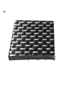
- FIG. 3 is a photograph of a CFRP plate before heat treatment.
- FIG. 4 is a photograph of the CFRP plate after undergoing the treatment according to Example 1-4.
- FIG. 5 is a photograph of the CFRP plate after undergoing the treatment according to Comparative Example 1-2.
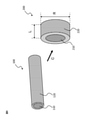
- FIG. 6 is a schematic view of the carbon fiber reinforced thermoplastic resin pellet according to the second invention of the present disclosure and the carbon fiber reinforced thermoplastic resin strand used in the process of manufacturing the pellet according to the second invention of the present disclosure. It is a schematic diagram.
- FIG. 7 is a schematic schematic diagram of a carbon fiber reinforced thermoplastic resin strand according to a third invention of the present disclosure.
- the method for decomposing a plastic-containing material according to the first invention of the present disclosure is as follows.
- the plastic-containing material is heated to the first surface temperature in the presence of the semiconductor material in an atmosphere in a heating furnace in which a low oxygen concentration gas having an oxygen concentration of less than 10% by volume is introduced, and the plastic in the plastic-containing material is heated.
- Disassembling including.
- FIG. 1 is a conceptual cross-sectional view for explaining the first disassembly method according to the present invention.
- the first decomposition mechanism of the plastic-containing material according to the present invention will be described below. There is no intention to limit the present invention by theory.
- the heat introduced for the decomposition of the plastic can be reduced as compared with the case where the semiconductor material is not used, and as a result, the energy consumption can be reduced.
- the inventors of the present invention can efficiently heat-treat the plastic while suppressing excessive oxidative heat generation by setting the oxygen concentration to a relatively low value even in the presence of the semiconductor material. I found out what I could do.
- the heat treatment is performed in the presence of the semiconductor material, good decomposition efficiency can be obtained even at a relatively low oxygen concentration, and oxygen in the heating furnace can be obtained.
- concentration By setting the concentration to a relatively low value, it is possible to suppress excessive oxidative heat generation and achieve a decomposition treatment with improved stability.
- FIG. 2 is a cross-sectional view schematically showing one embodiment of the decomposition method according to the first invention of the present disclosure.
- the heating furnace 20 shown in FIG. 2 has a heat source (heater) 23, a gas supply unit 24, an exhaust port 25, and an internal space 26.
- a porous carrier 21 is arranged in the internal space 26 of the heating furnace 20, and a semiconductor material is supported on the surface of the carrier 21.
- the plastic-containing material 22 is placed in contact with the carrier 21.
- the temperature of the atmosphere of the internal space 26 of the heating furnace 20 can be controlled via the heat source (heater) 23 of the heating furnace 20 so that the surface temperature of the plastic-containing material 22 becomes a specific temperature. ..
- the surface temperature of the plastic-containing material 22 can be measured via a temperature sensor 27 arranged within 5 mm from the surface of the plastic-containing material 22.
- a low oxygen concentration gas having an oxygen concentration of less than 10% by volume is introduced into the internal space 26 of the heating furnace 20 through the gas supply unit 24.
- the introduction rate of the low oxygen concentration gas according to the capacity in the furnace, the oxygen concentration in the atmosphere in the heating furnace 20 can be controlled.
- the low oxygen concentration gas can be pushed into the heating furnace through, for example, a gas supply unit provided in the heating furnace, or is sucked into the heating furnace by applying suction pressure to the exhaust port 25. Can be done.
- the low oxygen concentration gas is, for example, a mixed gas of air and nitrogen gas. By selecting the ratio of air and nitrogen gas, the oxygen concentration in the heating furnace can be controlled.
- the plastic-containing material is heated to a first surface temperature, for example, a first surface temperature of 300 ° C to 600 ° C, in an atmosphere in which the oxygen concentration is controlled to less than 10% by volume by introducing a low oxygen concentration gas.
- a first surface temperature for example, a first surface temperature of 300 ° C to 600 ° C
- the oxygen concentration is controlled to less than 10% by volume by introducing a low oxygen concentration gas.
- the plastic contained in the plastic-containing material 22 is decomposed into decomposition gases such as steam, carbon dioxide, and methane, and the decomposition gas is discharged from the exhaust port 25 of the heating furnace 20.
- the inorganic material contained in the plastic-containing material can be recovered after the heat treatment.
- the plastic-containing material contains plastic.
- the plastic-containing material may be a plastic material or a plastic composite material.
- plastic contained in the plastic-containing material examples include a thermoplastic resin and a thermosetting resin.
- thermoplastic resin contained in the plastic-containing material examples include polycarbonate (PC) resin, polyethylene (PE) resin, polypropylene (PP) resin, polyvinyl chloride (PVC) resin, polystyrene (PS) resin, and polyethylene terephthalate ( PET) resin, acrylonitrile-butadiene-styrene (ABS) resin, polyamide (PA) resin, polylactic acid (PLA) resin, polyimide (PI) resin, polymethylmethacrylate (PMMA) resin, methacrylic resin, polyvinyl alcohol (PVA) resin , Polyacetal resin, petroleum resin, AS resin, modified polyphenylene ether resin, polybutylene terephthalate (PBT) resin, polybutene (PB) resin, fluororesin, polyacrylate resin, polyether ether ketone (PEEK) resin, polyphenylene sulfide (PPS) Resin is mentioned.
- PC polycarbonate
- PE polyethylene
- PP polypropylene
- thermosetting resin contained in the plastic-containing material examples include phenol resin, urethane foam resin, polyurethane resin, urea resin, epoxy resin, unsaturated polyester resin, melamine resin, alkyd resin, vinyl ester resin, and cyanate resin. Can be mentioned.
- the plastic-containing material can contain at least one selected from the group consisting of the above-mentioned thermoplastic resin and thermosetting resin.
- the plastic-containing material is, in particular, a plastic composite material.
- the plastic composite material is, for example, fiber reinforced plastic (FRP).
- FRP fiber reinforced plastic
- Examples of the reinforcing fiber contained in the fiber-reinforced plastic include glass fiber (glass fiber), aramid fiber, and carbon fiber (carbon fiber).
- Carbon fiber reinforced plastic Plastic composites are, in particular, carbon fiber-containing plastic products such as carbon fiber reinforced plastics (CFRP). Carbon fiber reinforced plastic contains plastic and carbon fiber (carbon fiber material). The carbon fiber reinforced plastic may contain other members and / or materials (for example, reinforced fibers other than carbon fibers, resin molded products, metals, ceramics, etc.).
- the carbon fiber is not particularly limited, and examples thereof include PAN-based carbon fiber and pitch-based carbon fiber.
- the carbon fiber may be one kind or may be composed of two or more kinds.
- the carbon fiber contained in the carbon fiber reinforced plastic may be in any form, and may be, for example, a carbon fiber bundle, a woven fabric formed from the carbon fiber bundle, or a carbon fiber non-woven fabric.
- a low oxygen concentration gas having an oxygen concentration of less than 10% by volume is introduced into the atmosphere of the heating furnace.
- the oxygen concentration of the low oxygen concentration gas introduced into the atmosphere of the heating furnace is more than 0% by volume, 1% by volume or more, 2% by volume or more, 3% by volume or more, or 4% by volume or more, and / or. , 9% by volume or less, 8% by volume or less, or 7% by volume or less.
- the timing of introducing the low oxygen concentration gas into the heating furnace can be determined according to the type of plastic contained in the plastic-containing material, the surface temperature at which the decomposition of the plastic starts, and the like. Further, the timing of introducing the low oxygen concentration gas into the heating furnace can be determined based on the data acquired in advance regarding the self-heating of the plastic-containing material.
- a low oxygen concentration gas is applied to the atmosphere of the heating furnace while the surface temperature of the plastic-containing material held in the heating furnace is less than 300 ° C. Introduce inside.
- the oxygen concentration in the atmosphere of the heating furnace is less than 10% by volume while the surface temperature of the plastic-containing material held in the heating furnace is 250 ° C. or lower, 200 ° C. or lower, or 150 ° C. or lower. Introduce a certain low oxygen concentration gas.
- the lower limit of the surface temperature of the plastic-containing material held in the heating furnace when introducing a low oxygen concentration gas having an oxygen concentration of less than 10% by volume into the atmosphere of the heating furnace is not particularly limited, but for example. , 0 ° C or higher, 10 ° C or higher, 20 ° C or higher, or room temperature or higher.
- a low oxygen concentration gas having an oxygen concentration of less than 10% by volume is introduced into the atmosphere of the heating furnace, particularly in the atmosphere of the heating furnace holding a plastic-containing material having a surface temperature of less than 300 ° C. Introduced, thereby reducing the oxygen concentration of the atmosphere in the heating furnace to less than 10% by volume.
- a low oxygen concentration gas having an oxygen concentration of less than 10% by volume is introduced into the atmosphere of the heating furnace, particularly in the atmosphere of the heating furnace holding a plastic-containing material having a surface temperature of less than 300 ° C.
- the oxygen concentration in the atmosphere in the heating furnace is increased to more than 0% by volume, 1% by volume or more, 2% by volume or more, 3% by volume or more, or 4% by volume or more, and / or 9% by volume.
- control is performed to 8% by volume or less, or 7% by volume or less.
- the oxygen concentration in the heating furnace can be measured directly with an oxygen concentration meter (oxygen monitor), or can be determined based on the volume inside the furnace and the amount of gas introduced into the furnace.
- the oxygen concentration in the heating furnace is preferably the average oxygen concentration during the heat treatment.
- the introduction of the low oxygen concentration gas into the furnace can be performed, for example, by pushing the low oxygen concentration gas into the furnace through a gas supply unit provided in the heating furnace, or suction provided in the furnace. It can be done by sucking from the port (or exhaust port) so that the gas flows into the furnace from the gas supply unit provided at a place different from the suction port.
- the gas supply unit of the heating furnace may have, for example, an opening and / or may have a gas permeable material.
- the amount of gas introduced into the furnace can be set according to the capacity of the heating furnace, the desired oxygen concentration, etc., based on the unit resin amount of the resin to be decomposed (for example, epoxy resin).
- the amount of gas introduced into the furnace per unit amount of resin is determined in the range of 1 to 1000 (L / min) / kg or less, preferably in the range of 2 to 700 (L / min) / kg or less. Can be done.
- the time for replacing the atmosphere in the furnace with the introduced gas can be determined based on the determined gas introduction amount and the volume of the heating furnace used.
- the introduction amount of the low oxygen concentration gas is set with respect to the capacity in the furnace, whereby the atmosphere in the heating furnace is changed while the surface temperature of the plastic-containing material held in the heating furnace is less than 300 ° C. , Can be substituted by the introduced hypoxic gas.
- the low oxygen concentration gas introduced into the heating furnace can contain a diluting gas, and in particular, it is a mixed gas of air and the diluting gas.
- the diluting gas include nitrogen gas, carbon dioxide gas, steam, and superheated steam.
- the superheated steam is steam heated to a temperature equal to or higher than the boiling point. Superheated steam has the advantage of having a relatively high heat transfer property to the object to be decomposed.
- the heating furnace may be a combustion furnace or an electric furnace.
- the heating furnace is, for example, an internal space for accommodating a plastic-containing material and a semiconductor material, a heat source (heater) for heating the atmosphere in the heating furnace, and a gas supply for introducing a low oxygen concentration gas into the heating furnace. It can have a section, an exhaust port for discharging the decomposed gas, and optionally, a suction port for applying suction pressure to the inside of the heating furnace. It should be noted that one structure can also be used as an exhaust port and a suction port. As the exhaust port and / or the suction port, for example, one or more openings provided in the heating furnace can be used.
- the "surface temperature" of the plastic-containing material can be determined by measuring the temperature within 5 mm of the circumference of the plastic-containing material during the heat treatment.
- the surface temperature of the plastic-containing material can be controlled, for example, by controlling the temperature in the heating furnace via the heat source of the heating furnace, and / or introducing a low temperature gas into the heating furnace, and / Alternatively, it can be controlled by lowering the oxygen concentration and suppressing the heat generation of oxidation.
- the surface temperature of the plastic-containing material is measured via a temperature sensor located within 5 mm from the surface of the plastic-containing material, and this measured value is fed back to the heat source of the heating furnace to further increase the accuracy and surface temperature. It can also be controlled.
- data on the correlation between the temperature in the heating furnace and / or the output of the heat source and the surface temperature measured by the sensor may be acquired in advance, and the heat treatment may be performed based on this data. ..
- the method according to the first invention of the present disclosure The plastic-containing material is heated to the first surface temperature in the presence of the semiconductor material in an atmosphere in a heating furnace in which a low oxygen concentration gas having an oxygen concentration of less than 10% by volume is introduced, and the plastic in the plastic-containing material is heated. Disassembling, including.
- this heat treatment is carried out in an atmosphere where the oxygen concentration is less than 10% by volume due to the introduction of a low oxygen concentration gas having an oxygen concentration of less than 10% by volume, and in particular, more than 0% by volume and 1 Performed under an oxygen concentration of 9% by volume or more, 2% by volume or more, 3% by volume or more, or 4% by volume or more, and / or under an oxygen concentration of 9% by volume or less, 8% by volume or less, or 7% by volume or less. conduct.
- the “first surface temperature” is the surface temperature of the plastic-containing material.
- the “first surface temperature” can be determined by measuring the temperature within 5 mm around the plastic-containing material being heat-treated, similarly to the above-mentioned "surface temperature”.
- the first surface temperature may be 300 ° C. or higher, 325 ° C. or higher, or 350 ° C. or higher, and / or 600 ° C. or lower, 550 ° C. or lower, 500 ° C. or lower, or 450 ° C. or lower.
- the first surface temperature is, for example, 300 ° C. to 600 ° C., 300 ° C. to 550 ° C., 300 ° C. to 500 ° C., or 300 ° C. to 450 ° C.
- the plastic may not decompose. Further, when the first surface temperature exceeds the above range, when the plastic-containing material contains valuable resources such as carbon fibers, the valuable resources such as carbon fibers are deteriorated and / or burned down due to heating in the presence of oxygen. May be noticeable.
- the first surface temperature By setting the first surface temperature to a relatively low temperature, the effect of suppressing excessive oxidative heat generation is further enhanced.
- the first surface temperature is set to a temperature of 450 ° C. or higher during the heat treatment at an oxygen concentration of less than 10% by volume.
- the heating temperature is relatively low, the carbides formed on the surface of the plastic-containing material may suppress further decomposition of the plastic, but by setting the surface temperature to a temperature of 450 ° C or higher, the oxygen concentration is relatively relatively low. Carbide can be removed even if the temperature is low. Therefore, it is possible to further improve the decomposition efficiency of the plastic.
- the heat treatment is performed over a predetermined time under the introduction of a low oxygen concentration gas having an oxygen concentration of less than 10% by volume.
- This predetermined time may be 1 minute to 600 minutes, preferably 30 minutes to 300 minutes, and more preferably 60 minutes to 180 minutes.
- the time when the temperature of the heating furnace reaches 300 ° C. or the time when the start of decomposition of the plastic is confirmed can be set as the starting point of the above-mentioned "predetermined time".
- the semiconductor material may be placed in the heating furnace together with the plastic-containing material, or the semiconductor material may be placed in the heating furnace in advance, and then the plastic-containing material may be placed adjacent to or in contact with the semiconductor material. And may be arranged.
- the plastic-containing material and the semiconductor material to be heat-treated are arranged apart from each other at a distance of 50 mm or less.
- spacers placed between the plastic-containing material and the semiconductor material can be used.
- the lower limit of the distance is not particularly limited, but may be more than 0 mm, more than 1 mm, more than 5 mm, or more than 10 mm.
- the distance between the plastic-containing material and the semiconductor material can be measured at the place where they are closest to each other.
- the plastic-containing material and the semiconductor material to be heat-treated are arranged in contact with each other.
- the mode of contact between the plastic-containing material and the semiconductor material is not particularly limited.
- the two can be brought into contact with each other.
- the plastic-containing material may be placed on the semiconductor material supported on the surface of the carrier.
- the two can be brought into contact with each other by surrounding or covering at least a part or the whole of the plastic-containing material with the semiconductor material.
- the semiconductor material is not particularly limited as long as it is stable at the temperature and oxygen concentration of the present invention.
- the semiconductor material contains, for example, at least one selected from the group consisting of the following substances: BeO, MgO, CaO, SrO, BaO, CeO 2 , ThO 2 , UO 3 , U 3 O 8 , TIO 2 , ZrO 2 , V 2 O 5 , Y 2 O 3 , Y 2 O 2 S, Nb 2 O 5 , Ta 2 O 5 , MoO 3 , WO 3 , MnO 2 , Fe 2 O 3 , MgFe 2 O 4 , NiFe 2 O 4 , ZnFe 2 O 4 , ZnCo 2 O 4 , ZnO, CdO, Al 2 O 3 , MgAl 2 O 4 , ZnAl 2 O 4 , Tl 2 O 3 , In 2 O 3 , SiO 2 , SnO 2 , PbO 2 , UO 2 , Cr
- the semiconductor material is an oxide semiconductor material.
- oxide semiconductor materials include chromium oxide, titanium oxide, zinc oxide, vanadium oxide, tungsten oxide, molybdenum oxide, cobalt oxide, iron oxide, and copper oxide.
- the form of the semiconductor material is not particularly limited, and may be, for example, a plate shape, a granular shape, or a honeycomb shape. From the viewpoint of accelerating the decomposition of the plastic, it is preferable that the semiconductor material is supported on the surface of the carrier having breathability.
- the carrier having breathability may be a porous body made of ceramics or the like, a honeycomb-shaped support, or the like.
- the semiconductor material may be a sintered body of a semiconductor.
- the heat treatment method according to one preferred embodiment of the first invention according to the present disclosure is To heat the plastic-containing material subjected to the heat treatment at the first surface temperature in the presence of a semiconductor material in an atmosphere having an oxygen concentration of 10% by volume or more. including.
- the heat treatment at an oxygen concentration of 10% by volume or more is preferably carried out under an oxygen concentration of more than 10% by volume, 12% by volume or more, 15% by volume or more, or 20% by volume or more, and / or 30% by volume. It is carried out below or at an oxygen concentration of 25% by volume or less.
- the plastic-containing material heat-treated at a relatively low oxygen concentration is further heat-treated under an increased oxygen concentration.
- the heat treatment with the introduction of a low oxygen concentration gas having an oxygen concentration of less than 10% by volume and the heat treatment with an oxygen concentration of 10% by volume or more can be continuously performed in the same heating furnace. That is, for example, after heating the plastic-containing material to the first surface temperature, the oxygen concentration can be increased to 10% by volume or more in the same heating furnace, and further heat treatment can be performed.
- the conventional plastic decomposition method it is necessary to perform processing such as shredding of the object to be processed after batch processing, but heat treatment under the introduction of a low oxygen concentration gas having an oxygen concentration of less than 10% by volume and oxygen.
- An atmosphere having an oxygen concentration of 10% by volume or more can be formed, for example, by introducing a high oxygen concentration gas having an oxygen concentration of 10% by volume or more into the heating furnace, and in particular, air and / or oxygen gas in the heating furnace. Can be formed by introducing.
- the oxygen concentration of the high oxygen concentration gas may be more than 10% by volume, 12% by volume or more, 15% by volume or more, or 20% by volume or more, and / or 30% by volume or less, or 25% by volume or less. It's okay.
- the semiconductor material used in the heat treatment at the first surface temperature can be used.
- the plastic-containing material subjected to the heat treatment at the first surface temperature is heated to the second surface temperature in the presence of the semiconductor material in an atmosphere having an oxygen concentration of 10% by volume or more.
- the “second surface temperature” is the surface temperature of the plastic-containing material to be treated.
- the “second surface temperature” can be determined by measuring the temperature within 5 mm around the plastic-containing material being heat-treated, similarly to the above-mentioned “surface temperature” and "first surface temperature”.
- the second surface temperature may be in the range of 400 ° C to 600 ° C. More preferably, the second surface temperature is 425 ° C to 575 ° C, or 450 ° C to 550 ° C.
- the decomposition efficiency may not be improved. Further, when the second surface temperature exceeds the above range, when the plastic-containing material contains valuable resources such as carbon fibers, the valuable resources such as carbon fibers are deteriorated and / or burned down due to heating in the presence of oxygen. May be noticeable.
- the second surface temperature may be substantially the same as the first surface temperature.
- the second surface temperature may be equal to or higher than the first surface temperature, or is at least 5 ° C, at least 10 ° C, at least 25 ° C, at least 50 ° C, or at least 75 ° C higher than the first surface temperature. good.
- the upper limit of the difference between the first surface temperature and the second surface temperature is not particularly limited, but may be, for example, 200 ° C. or lower, or 100 ° C. or lower.
- the heat treatment with an oxygen concentration of 10% by volume or more can be performed over a predetermined time.
- This predetermined time may be, for example, 1 minute to 600 minutes, 60 minutes to 360 minutes, or 90 minutes to 300 minutes.
- ⁇ Use> According to the method for decomposing a plastic-containing material according to the first invention of the present disclosure, a wide range of plastics can be efficiently vaporized and decomposed. Further, the decomposition method according to the first invention of the present disclosure can be applied to volatile organic compounds (VOC), flue gas, particulate matter (PM) and the like, and can also be used for exhaust gas treatment.
- VOC volatile organic compounds
- PM particulate matter
- the first invention of the present disclosure also relates to a method for recovering an inorganic material contained in a plastic composite material.
- the plastic-containing material which is a plastic composite material, contains a plastic and an inorganic material
- this recovery method is: Disassembling the plastic in the plastic-containing material by the decomposition method according to the first aspect of the present disclosure to recover the inorganic material.
- the above description regarding the decomposition method of the plastic-containing material can be referred to.
- the plastic can be efficiently decomposed. Therefore, according to the recovery method according to the first invention of the present disclosure, the plastic contained in the plastic composite material can be efficiently and selectively decomposed, so that the inorganic material having good physical properties can be efficiently decomposed. Can be collected in.
- the inorganic material can be recovered without crushing the plastic composite material. It should be noted that crushing the plastic composite material is not particularly excluded, and crushing can be performed arbitrarily.
- the plastic-containing material as a plastic composite material is subjected to two-step heating. That is, the plastic is decomposed by subjecting the plastic composite material to heating under the introduction of a low oxygen concentration gas (oxygen concentration less than 10%) and subsequent heat treatment at an oxygen concentration of 10% by volume or more. And recover the inorganic material.
- a low oxygen concentration gas oxygen concentration less than 10%
- the plastic composite material When recovering an inorganic material, it is desirable to suppress deterioration of the physical properties of the inorganic material due to excessive oxidative heat generation, and further, it is desirable to suppress deterioration of the physical properties of the inorganic material due to carbonization of the plastic and adhesion to the inorganic material and remaining. Is preferable.
- the physical properties of the inorganic material deteriorate due to the excessive heat generation of oxidation because the oxygen concentration is relatively low at the initial stage where excessive heat generation of oxidation is likely to occur. It is suppressed.
- the heat treatment is performed after that, the oxygen concentration is increased, so that the carbonized resin remaining on the inorganic material can be efficiently removed. As a result, even better physical properties of the recovered inorganic material can be ensured by the method of recovering the inorganic material through the two-step heat treatment.
- plastic composite materials containing inorganic materials and plastics include fiber reinforced plastics (FRP), particularly carbon fiber reinforced plastics.
- FRP fiber reinforced plastics
- the inorganic material examples include inorganic fibers, for example, alumina fibers, ceramic fibers, silica fibers and the like.
- the inorganic fiber is, in particular, carbon fiber (carbon fiber material).
- the carbon fiber is not particularly limited, and examples thereof include PAN-based carbon fiber and pitch-based carbon fiber.
- the carbon fiber may be one kind or may be composed of two or more kinds.
- the carbon fiber may be in any form, and may be, for example, a carbon fiber bundle, a woven fabric formed from the carbon fiber bundle, or a non-woven carbon fiber.
- the residual carbon derived from the plastic recovered together with the inorganic material is reduced, and in particular, the residual carbon is recovered from the inorganic material. It is 5% by weight or less.
- the residual carbon is 4% by weight or less, 3% by weight or less, 2% by weight or less, 1% by weight or less, 0.9% by weight or less, 0.5% by weight or less, or It is 0.1% by weight or less. It is preferable that the residual carbon is reduced as much as possible, but the lower limit thereof may be 0.001% by weight or more.
- the amount of the residual carbon in the recovered inorganic material can be measured in the same manner as the amount of the residual carbon in the regenerated carbon fiber described later.
- the recovery method according to the first invention of the present disclosure it is possible to recover carbon fiber having better physical properties than the carbon fiber before manufacturing the carbon fiber reinforced plastic.
- carbon fiber having a single fiber tensile strength of 3.0 GPa or more and a wibble shape coefficient of 6.0 or more can be obtained as an inorganic material from carbon fiber reinforced plastic. Obtainable.
- the single fiber tensile strength is preferably 3.1 GPa or more, 3.2 GPa or more, 3.3 GPa or more, or 3.4 GPa or more.
- the upper limit of the tensile strength of the single fiber is not particularly limited, but may be 6.0 GPa or less.
- Single fiber tensile strength can be measured according to JIS R7606 as follows: At least 30 single fibers are collected from the fiber bundle and The diameter of the single fiber is measured in the side image of the single fiber taken with a digital microscope, and the cross-sectional area is calculated. The sampled single fiber is fixed to the perforated mount with an adhesive, and A mount on which a single fiber was fixed was attached to a tensile tester, and a tensile test was performed at a test length of 10 mm and a strain rate of 1 mm / min to measure the tensile breaking stress. The tensile strength is calculated from the cross-sectional area of the single fiber and the tensile breaking stress. The average of the tensile strengths of at least 30 single fibers is defined as the single fiber tensile strength.
- the Weibull shape coefficient is preferably 6.5 or more, 7.0 or more, 7.5 or more, 8.0 or more, or 8.5 or more.
- the upper limit of the Weibull shape coefficient is not particularly limited, but may be 15.0 or less.
- the high Weibull shape coefficient of the single fiber tensile strength means that the variation in the single fiber tensile strength is small.
- F is the fracture probability obtained by the symmetric sample cumulative distribution method
- ⁇ is the single fiber tensile strength (MPa)
- m is the Weibull shape coefficient
- C is a constant.
- Weibull plotting with lnln ⁇ 1 / (1-F) ⁇ and ln ⁇ can be performed, and the Weibull shape coefficient m can be obtained from the slope that is first-order approximated.
- the metal material is recovered from the plastic-containing material containing the plastic and the metal material.
- a method for recovering a metallic material including the following:
- the plastic-containing material contains the plastic and the metal material, and the plastic in the plastic-containing material is decomposed by the decomposition method according to the first aspect of the present disclosure to recover the metal material.
- metal materials include gold and rare metals.
- Examples of the metal material and the plastic composite material containing plastic include a composite material having a metal material contained in a matrix resin, and in particular, a solar cell panel, an electronic component, and an electronic circuit.
- the regenerated carbon fiber (regenerated carbon fiber material) according to the first invention of the present disclosure can be produced by recovering carbon fiber from carbon fiber reinforced plastic.
- the regenerated carbon fiber can have better physical properties than the carbon fiber before producing the carbon fiber reinforced plastic.
- the method for producing recycled carbon fiber is not particularly limited.
- the regenerated carbon fiber can be produced by recovering the regenerated carbon fiber from the carbon fiber reinforced plastic by the recovery method according to the first invention of the present disclosure.
- the regenerated carbon fiber has a single fiber tensile strength of 3.0 GPa or higher and a Weibull shape coefficient of 6.0 or higher.
- the single fiber tensile strength and the Weibull shape coefficient can be measured and determined by the methods described above.
- the single fiber tensile strength of the regenerated carbon fiber is preferably 3.1 GPa or more, 3.2 GPa or more, 3.3 GPa or more, or 3.4 GPa or more.
- the upper limit of the tensile strength of the single fiber is not particularly limited, but may be 6.0 GPa or less.
- the Weibull shape coefficient of the regenerated carbon fiber is preferably 6.5 or more, 7.0 or more, 7.5 or more, 8.0 or more, or 8.5 or more.
- the upper limit of the Weibull shape coefficient is not particularly limited, but may be 15.0 or less.
- a method for producing a regenerated carbon fiber having a single fiber tensile strength of 3.0 GPa or more and a Weibull shape coefficient of 6.0 or more is available.
- the plastic-containing material is heated to the first surface temperature in the presence of the semiconductor material in an atmosphere in a heating furnace into which a low oxygen concentration gas having an oxygen concentration of less than 10% by volume is introduced, and the plastic in the plastic-containing material is heated.
- the plastic-containing material is carbon fiber reinforced plastic containing carbon fiber.
- a method for producing a regenerated carbon fiber having a single fiber tensile strength of 3.0 GPa or more and a Weibull shape coefficient of 6.0 or more is used.
- the plastic-containing material is heated to the first surface temperature in the presence of the semiconductor material in an atmosphere in a heating furnace into which a low oxygen concentration gas having an oxygen concentration of less than 10% by volume is introduced, and the first surface temperature is concerned.
- the plastic in the plastic-containing material is decomposed.
- the plastic-containing material is carbon fiber reinforced plastic containing carbon fiber.
- a low oxygen concentration gas having an oxygen concentration of less than 10% by volume is used while the surface temperature of the plastic-containing material is less than 300 ° C. Introduce into the atmosphere of the heating furnace.
- the amount of residual carbon is reduced, and in particular, the residual carbon is 5% by weight or less with respect to the regenerated carbon fiber.
- the residual carbon is 4% by weight or less, 3% by weight or less, 2% by weight or less, 1% by weight or less, 0.9% by weight or less, 0.5% by weight or less, based on the regenerated carbon fiber. Or 0.1% by weight or less.
- the amount of residual carbon is preferably reduced as much as possible, and the lower limit thereof is not particularly limited, but may be, for example, 0.01% by weight or more with respect to the regenerated carbon fiber.
- residual carbon is a carbonized component derived from the plastic contained in the carbon fiber reinforced plastic which is a raw material for producing recycled carbon fiber.
- the amount of residual carbon (residual carbon component) in the regenerated carbon fiber can be determined by thermogravimetric analysis (TGA).
- thermogravimetric analysis can be performed by the following procedure: (I) An air supply rate of 0.2 L / min, a heating rate of 5 ° C./min, and 1/1 in a thermogravimetric analyzer for 1 to 4 mg of a sample piece obtained by crushing recycled carbon fiber. At a recording speed of 6s, Temperature rise from room temperature to 100 ° C, Holding at 100 ° C for 30 minutes, Temperature rise from 100 ° C to 400 ° C, and It has a process of holding at 400 ° C and performs thermogravimetric analysis for a total of 300 minutes.
- thermogravimetric analysis with retention at 400 ° C. for 480 minutes may be performed instead of a total of 300 minutes of thermogravimetric analysis. Further, instead of holding at 400 ° C. for 480 minutes, it may be held at a specific temperature within the range of more than 400 ° C. and 500 ° C. or lower for 480 minutes.
- the above measurement can be performed after removing the resin.
- the plastic-containing material is heated to the first surface temperature in the presence of the semiconductor material in an atmosphere in a heating furnace into which a low oxygen concentration gas having an oxygen concentration of less than 10% by volume is introduced, and the plastic in the plastic-containing material is heated.
- the plastic-containing material is carbon fiber reinforced plastic containing carbon fiber.
- the plastic-containing material is heated to the first surface temperature in the presence of the semiconductor material in an atmosphere in a heating furnace into which a low oxygen concentration gas having an oxygen concentration of less than 10% by volume is introduced, and the first surface temperature is concerned.
- the plastic in the plastic-containing material is decomposed.
- the plastic-containing material is carbon fiber reinforced plastic containing carbon fiber.
- the second invention of the present disclosure relates to a blended yarn of regenerated carbon fiber and a thermoplastic resin fiber, and a carbon fiber reinforced thermoplastic resin pellet formed from the blended yarn.
- the second invention of the present disclosure relates to a method for producing them.
- the blended yarn of the regenerated carbon fiber and the thermoplastic resin fiber according to the second invention of the present disclosure is
- the regenerated carbon fiber has a single fiber tensile strength of 3.0 GPa or more and a wibble shape coefficient of 6.0 or more, and the regenerated carbon fiber contains a residual carbon component, and the content of the residual carbon component is the regenerated carbon fiber. It should be more than 0% by weight and less than 5.0% by weight. It is characterized by.
- the blended yarn according to the second invention of the present disclosure can be produced by a general spinning method.
- This spinning method may include each step of cotton carding, kneading, and rough spinning.
- the cotton carding step may be a step of separating and unraveling an aggregate of each discontinuous fiber, opening the fiber, and orienting the mixed single fibers in one direction to produce a thick sliver
- the kneading step may be a step.
- the sliver may be a step of combining several slivers and further improving the fiber orientation while stretching the sliver
- the roving step may be a step of winding the blended yarn by further stretching and twisting the sliver.
- each fiber Since the tensile strength of the sliver is given by the frictional force due to the contact or entanglement of the single fibers, each fiber is satisfactorily opened, and the contact area or entanglement between the single fibers is increased to improve the tensile strength. It is possible to suppress a decrease in tensile strength by suppressing single fiber breakage and not increasing the number of joints between single fibers. By strengthening the twist, the contact area between the single fibers increases, so that the tensile strength is improved. Oil may be applied to each fiber or sliver as needed to supplement the frictional force.
- carbon fibers have no crimping property and high surface smoothness, so that the entanglement between single fibers is weak, and further, they have a high elastic modulus and low elongation and are hard, so that they are relatively easy to break and break. ..
- the thermoplastic resin fiber blended with the regenerated carbon fiber has an effect of enhancing the entanglement between the single fibers, and even if a small amount of the thermoplastic resin fiber is blended, the tensile strength of the sliver is greatly improved.
- the blended yarn according to the second invention of the present disclosure has a high wibble shape coefficient in the single fiber tensile strength of the regenerated carbon fiber, so that the variation in tensile strength is small and the same tensile strength is obtained. It is considered that the single fiber breakage of the regenerated carbon fiber is relatively suppressed because the number of single fibers having low tensile strength is relatively small as compared with the general unused carbon fibers having.
- the general characteristics of the regenerated carbon fiber obtained by the method of heat treatment and decomposition are that the tensile strength tends to decrease due to the formation of oxidation defects in the regenerated carbon fiber, and the carbon dioxide of the resin component is used as the residual carbon component. May be contained in recycled carbon fiber.
- the residual carbon component may firmly bind the single fibers of the regenerated carbon fiber to each other. In the production of spun yarn, the residual carbon component is considered to prevent the opening of fibers in the cotton carding process and the entanglement of single fibers.
- the blended yarn according to the second invention of the present disclosure uses recycled carbon fiber having a relatively low content of residual carbon component as a raw material, so that entanglement between single fibers can be obtained. easy.
- the blended yarn according to the second invention of the present disclosure is stably manufactured without causing yarn pull-out due to the tension of the spinning process because the frictional force due to the entanglement of the single fibers is easily obtained. It is considered that the tensile strength for this is easy to obtain.
- the second invention of the present disclosure also includes carbon fiber reinforced thermoplastic resin pellets having the above-mentioned blended yarn.
- This carbon fiber reinforced thermoplastic resin pellet is Having a core sheath structure,
- the blended yarn is the core component, and the thermoplastic resin is the sheath component. It is characterized by.
- the carbon fiber reinforced thermoplastic resin pellet according to the second invention of the present disclosure is a general long fiber reinforced pellet except that the blended yarn according to the second invention of the present disclosure is used as a substitute for continuous carbon fiber. Since it can be manufactured by cutting the resin strands obtained by coating the blended yarn with a thermoplastic resin in the same manner as the manufacturing method, the resin strands in which discontinuous carbon fibers are kneaded and dispersed in the thermoplastic resin can be obtained. It can contain regenerated carbon fiber with a relatively long fiber length as compared to the short fiber reinforced pellets produced by cutting. That is, the carbon fiber reinforced thermoplastic resin pellet according to the second invention of the present disclosure can be supplied to an injection molding machine or the like to produce a carbon fiber-containing product having excellent mechanical properties and the like.
- the recycled carbon fiber contains a carbon fiber component and a carbon component other than the carbon fiber component (particularly, a residual carbon component).
- the carbon component other than the carbon fiber component is attached to the surface of the carbon fiber component.
- the regenerated carbon fiber according to the second invention of the present disclosure has a single fiber tensile strength of 3.0 GPa or more and a wible shape coefficient of 6.0 or more, and also contains a residual carbon component, and the residual carbon component is contained.
- the amount is more than 0% by weight and 5.0% by weight or less with respect to the regenerated carbon fiber.
- the regenerating method is not particularly limited, and for example, it may be a regenerated carbon fiber obtained by heat-treating a carbon fiber-containing plastic product such as carbon fiber reinforced plastic (CFRP). ..
- the regenerated carbon fiber is a regenerated carbon fiber obtained by a semiconductor thermoactive method. That is, a particularly preferable embodiment of the present disclosure includes regenerated carbon fibers produced by decomposing a plastic component contained in a carbon fiber-containing plastic product by a semiconductor thermoactive method.
- the "semiconductor thermal activation method” is a method of decomposing a compound to be decomposed such as a polymer by utilizing the thermal activity of a semiconductor (Thermal Activation of Semi-conductors, TASC).
- the above description regarding the first invention can be referred to. That is, the second invention of the present disclosure (and the third and third below) by recovering the carbon fiber from the plastic-containing material containing the plastic and the carbon fiber by using the above-mentioned decomposition method according to the first invention.
- a regenerated carbon fiber having the characteristics according to the fourth invention can be obtained.
- the single fiber tensile strength is preferably 3.1 GPa or more, 3.2 GPa or more, 3.3 GPa or more, or 3.4 GPa or more.
- the upper limit of the tensile strength of the single fiber is not particularly limited, but may be 6.0 GPa or less.
- the single fiber tensile strength can be measured as described above with respect to the first invention in accordance with JIS R7606:
- the Weibull shape coefficient is preferably 6.5 or more, 7.0 or more, 7.5 or more, 8.0 or more, or 8.5 or more.
- the upper limit of the Weibull shape coefficient is not particularly limited, but may be 15.0 or less.
- the high Weibull shape coefficient of the single fiber tensile strength means that the variation in the single fiber tensile strength is small.
- the Weibull shape coefficient can be calculated as described above with respect to the first invention.
- the carbon fiber component in the regenerated carbon fiber is usually derived from the carbon fiber contained in the carbon fiber-containing product or the like which is the raw material of the regenerated carbon fiber.
- the carbon fiber component in the regenerated carbon fiber may be modified by undergoing heat treatment or the like in the process of producing the regenerated carbon fiber.
- the carbon fiber component in the regenerated carbon fiber may be, for example, a PAN-based carbon fiber or a pitch-based carbon fiber.
- the form of the carbon fiber component in the regenerated carbon fiber is not particularly limited, but may be the form of a carbon fiber bundle composed of a plurality of single yarns (single fibers, filaments).
- the number of filaments constituting the carbon fiber bundle may be in the range of 1,000 to 80,000 or 3,000 to 50,000.
- the diameter of the filament constituting the carbon fiber component in the regenerated carbon fiber may be 0.1 ⁇ m to 30 ⁇ m, 1 ⁇ m to 10 ⁇ m, or 3 ⁇ m to 8 ⁇ m.
- the residual carbon component contained in the regenerated carbon fiber is particularly the residual carbon derived from the resin contained in the carbon fiber-containing plastic product used as a raw material in producing the regenerated carbon fiber.
- the residual carbon component is more than 0% by weight and 5.0% by weight or less with respect to the regenerated carbon fiber. In this case, it is possible to obtain a blended yarn having improved yarn pull-out resistance to the tension of the spinning process.
- the residual carbon component is more than 0% by weight and 5.0% by weight or less, contamination due to a relatively large amount of carbon component (particularly charcoal) can be avoided, and the blended yarn is used as a material. It is possible to reduce the carbon component that can become a foreign substance when manufacturing a carbon fiber-containing product or the like.
- the residual carbon component is 4.0% by weight or less, 3.0% by weight or less, or 2.0% by weight or less with respect to the regenerated carbon fiber.
- the residual carbon component is preferably reduced as much as possible, but 0.01% by weight or more, 0.1% by weight or more, 0.2% by weight or more, 0.4% by weight or more, 0 with respect to the carbon fiber. It may be 6.6% by weight or more, 0.8% by weight or more, 1.0% by weight or more, or 1.2% by weight or more.
- the content of the residual carbon component in the regenerated carbon fiber can be measured by the thermogravimetric analysis method (TGA method) as described above with respect to the first invention.
- thermoplastic resin fibers contained in the blended yarn according to the second invention of the present disclosure include polyolefin resin fibers (for example, polypropylene resin fibers and polyethylene resin fibers), polyester resin fibers (for example, polyethylene terephthalate resin fibers, and polybutylene). (Telephthalate resin fiber and polylactic acid resin fiber), polyamide resin fiber, polyether ketone resin fiber, polycarbonate resin fiber, phenoxy resin fiber, and polyphenylene sulfide resin fiber.
- the thermoplastic resin fiber may be only one kind, or may be a mixture of two or more kinds of thermoplastic resin fibers.
- the second blended yarn according to the present invention is a spun yarn containing regenerated carbon fiber and thermoplastic resin fiber.
- the blended yarn may also include, for example, a binder applied to the regenerated carbon fiber.
- the blended yarn may be a spun yarn substantially composed of regenerated carbon fiber and thermoplastic resin fiber.
- the content of the regenerated carbon fiber contained in the blended yarn according to the second invention is preferably more than 50% by weight and 98% by weight or less with respect to the blended yarn. Particularly preferably, it may be more than 55% by weight, more than 60% by weight, more than 65% by weight, or more than 70% by weight, and / or 97% by weight or less, 96% by weight or less, 95% by weight or less, 94% by weight. % Or less, 93% by weight or less, 92% by weight or less, 91% by weight or less, or 90% by weight or less.
- the thermoplastic resin is used for the purpose of increasing the carbon fiber content when the carbon fiber reinforced thermoplastic resin pellets according to the present disclosure are produced using the regenerated carbon fiber. It is not necessary to reduce the amount of coating in the fiber, and the stability of the coating process is improved.
- the content of the regenerated carbon fiber is 98% by weight or less, the entanglement with the thermoplastic resin fiber to be blended becomes sufficient, and the yarn loss due to the tension in the spinning process is less likely to occur.
- the content of the thermoplastic resin fiber contained in the blended yarn according to the second invention may be 50% by weight or less, 40% by weight or less, or 30% by weight or less with respect to the blended yarn, and /. Alternatively, it may be more than 3% by weight, more than 4% by weight, more than 5% by weight, more than 6% by weight, more than 7% by weight, more than 8% by weight, more than 9% by weight, or more than 10% by weight.
- the regenerated carbon fiber contained in the blended yarn according to the second invention can have an average length of 20 mm or more and 80 mm or less. Fibers having a length in this range can be obtained, for example, by cutting fibers having a relatively long size.
- the average length of the regenerated carbon fiber may be 20 mm or more, 30 mm or more, or 40 mm or more, and / or 80 mm or less, 70 mm or less, or 60 mm or less.
- the thermoplastic resin fiber contained in the second blended yarn according to the present invention can have an average length of 20 mm or more and 80 mm or less. Fibers having a length in this range can be obtained, for example, by cutting fibers having a relatively long size.
- the average length of the thermoplastic resin fiber may be 20 mm or more, 30 mm or more, or 40 mm or more, and / or 80 mm or less, 70 mm or less, or 60 mm or less.
- the yarn pull-out resistance to the spinning process tension of the sliver can be improved.
- the average length of the regenerated carbon fiber and the thermoplastic resin fiber is 80 mm or less, it is possible to reduce the wrapping around the manufacturing equipment parts.
- the average lengths of the regenerated carbon fibers and the thermoplastic resin fibers are measured by measuring the lengths of 50 fibers visually with a nogis or the like, or in an image acquired with a digital camera or an optical microscope. It can be calculated by averaging the values.
- the blended yarn of the regenerated carbon fiber and the thermoplastic resin fiber according to the second invention of the present disclosure can be produced by a general spinning method. That is, in the method for producing a blended yarn according to the second invention of the present disclosure, an aggregate of discontinuous fibers is separated and opened, and the mixed single fibers are oriented in one direction to produce a thick sliver. It may include a cotton carding process, a kneading process in which several slivers are combined and stretched to further improve the degree of fiber orientation, and a crude spinning process in which the sliver is further stretched and twisted to wind up the blended yarn.
- a binder can be applied when producing the second blended yarn according to the present invention.
- the binder has, in particular, a role of promoting the binding of the regenerated carbon fiber to the thermoplastic resin fiber.
- the timing of applying the binder is not particularly limited, but it may be applied directly to the regenerated carbon fiber, or may be applied to a blended yarn containing the regenerated carbon fiber and the thermoplastic resin fiber.
- the binder may be, for example, an epoxy resin.
- the method of applying the binder is not particularly limited, and a known method can be used.
- the binder can be applied by immersing the regenerated carbon fiber or the blended yarn in a solution or dispersion of the binder and drying it. can.
- the amount of the binder may be 0.1% by weight to 25% by weight or 1% by weight to 20% by weight with respect to the regenerated carbon fiber.
- a carbon fiber reinforced thermoplastic resin pellet having a core-sheath structure which comprises a blended yarn according to the second invention of the present disclosure as a core component and a thermoplastic resin as a sheath component. .. Since the pellet according to the second invention of the present disclosure contains regenerated carbon fiber having a relatively long fiber length as compared with a short fiber reinforced pellet obtained by kneading and dispersing recycled carbon fiber in a thermoplastic resin, it is injected. By being supplied to a molding machine or the like, it is possible to manufacture a carbon fiber-containing product having excellent mechanical properties and the like.
- the carbon fiber reinforced thermoplastic resin pellet having a core-sheath structure according to the second invention of the present disclosure is to produce a carbon fiber reinforced thermoplastic resin strand by coating a blended yarn with a thermoplastic resin, and to obtain the strand. It can be produced by a method including cutting, and more specifically, as described above, except that the blended yarn according to the second invention of the present disclosure is used instead of the continuous carbon fiber, it is a general length. Similar to the method for producing fiber-reinforced pellets, it can be produced by cutting resin strands coated with a thermoplastic resin.
- the coating process in which the blended yarn that is continuously conveyed while being rewound is threaded through a die in which the thermoplastic resin melted from a supply port different from the blended yarn is continuously supplied, and the carbon fiber reinforcement discharged from the die. It can be manufactured by a method comprising a cutting step in which the thermoplastic resin strands are cut after being cooled.
- thermoplastic resin that is, the thermoplastic resin constituting the sheath component of the pellet
- the thermoplastic resin used for the coating treatment in the production of the pellet according to the second aspect of the present invention
- a polyolefin resin for example, polypropylene resin and polyethylene resin
- a polyester resin that is, a polyester resin
- polyamide resin, polyether ketone resin, polycarbonate resin, phenoxy resin, and polyphenylene sulfide resin can be mentioned.
- This thermoplastic resin may be only one kind, or may be a mixture of two or more kinds of thermoplastic resins.
- thermoplastic resin constituting the sheath component of the pellet according to the second invention may be of the same type as or different from the thermoplastic resin fiber contained in the blended yarn according to the second invention of the present disclosure. It may be a type.
- the melting point (T0 (° C.)) of the thermoplastic resin constituting the sheath component of the pellet is 10 (° C.) higher than the melting point (T1 (° C.)) of the thermoplastic resin fiber contained in the blended yarn according to the present disclosure. ) Very low is preferable. In this case, when the carbon fiber reinforced thermoplastic resin pellets according to the present disclosure are produced, the thermoplastic resin fibers contained in the blended yarn are suppressed from melting, and only the thermoplastic resin covering the blended yarn melts.
- T1-T0 The upper limit of the difference (T1-T0) between T1 and T0 is not particularly limited, but is, for example, 200 (° C.) or less, 150 (° C.) or less, 100 (° C.) or less, or 50 (° C.) or less. May be.
- thermoplastic resins used for the coating treatment include various types as long as the mechanical strength is not impaired for the purpose of improving fluidity, appearance gloss, flame retardant properties, thermal stability, weather resistance, impact resistance and the like.
- Polymers, fillers, stabilizers, pigments and the like may be blended.
- the carbon fiber reinforced thermoplastic resin pellet according to the second invention of the present disclosure cuts the carbon fiber reinforced thermoplastic resin strand obtained by coating the blended yarn according to the second invention of the present disclosure with a thermoplastic resin ( Since it is manufactured by slicing), the blended yarn is the core component and the thermoplastic resin is the sheath component.
- the thermoplastic resin as the sheath component is 50 weight by weight with respect to 100 parts by weight of the regenerated carbon fiber contained in the blended yarn.
- the amount is preferably from 100 parts by weight to 1000 parts by weight, more preferably from 100 parts by weight to 750 parts by weight, and most preferably from 250 parts by weight to 500 parts by weight.
- the cut length of the pellet according to the second invention is preferably 3 mm or more and 10 mm or less. Particularly preferably, it may be 5 mm or less.
- the cut length of the pellet corresponds, in particular, to the length of the core structure of the pellet in the axial direction.
- the cut length of the pellet is 3 mm or more, the average length of the regenerated carbon fiber becomes relatively long, so that the mechanical properties of the carbon fiber-containing product using the pellet as a molding raw material can be further improved.
- the cut length of the pellet is 10 mm or less, the regenerated carbon fiber is easily dispersed during the molding process, and the mechanical properties of the carbon fiber-containing product can be further improved.
- the diameter of the core-sheath type pellet is not particularly limited, but may be 1/10 or more and 2 times or less of the cut length of the pellet, and may be 1/4 or more and 1 time or less of the cut length of the pellet. preferable. If the diameter of the pellet is too small, some parts may not be covered. On the contrary, if the diameter of the pellet is too large, poor engagement with the molding machine may occur and molding may become difficult.
- the cut length and diameter of the pellets For the cut length and diameter of the pellets, measure the cut length or diameter of 30 or more pellets visually using a caliper or the like, or in an image acquired with a digital camera or an optical microscope, and average the measured values. By doing so, it can be calculated.
- FIG. 6 is a schematic view schematically showing a carbon fiber reinforced thermoplastic resin pellet 200 having a core-sheath structure according to the second invention of the present disclosure.
- the figure is a schematic diagram for illustration purposes and is not in scale.
- the pellet 200 having a core-sheath structure has a core component 210 and a sheath component 220. Further, the pellet 200 has a cut length L and a diameter R.
- the pellet 200 having a core-sheath structure cuts (cutting treatment, “C” in FIG. 6) a carbon fiber-reinforced thermoplastic resin strand 100 having a core-sheath structure having a core component 110 made of a blended yarn and a sheath component 120 made of a thermoplastic resin. ) Can be manufactured.
- the third invention of the present disclosure relates to a carbon fiber reinforced thermoplastic resin strand containing a blended yarn of regenerated carbon fiber and thermoplastic resin fiber, which is suitable for three-dimensional modeling.
- the third invention of the present disclosure relates to a method for producing them.
- the carbon fiber reinforced thermoplastic resin strand according to the third invention of the present disclosure has a blended yarn containing regenerated carbon fiber and thermoplastic resin fiber.
- This blended yarn of recycled carbon fiber and thermoplastic resin fiber is
- the regenerated carbon fiber has a single fiber tensile strength of 3.0 GPa or more and a wibble shape coefficient of 6.0 or more, and the regenerated carbon fiber contains a residual carbon component, and the content of the residual carbon component is the regenerated carbon. More than 0% by weight and less than 5.0% by weight with respect to the fiber, It is characterized by.
- the carbon fiber reinforced thermoplastic resin strand comprises the above-mentioned blended yarn.
- the blended yarn according to the third invention of the present disclosure is manufactured by a general spinning method, and may include each step of a cotton carding step, a kneading step, and a roving step. For each of these steps, the above description of the second invention can be referred to.
- each fiber Since the tensile strength of the sliver is given by the frictional force due to the contact or entanglement of the single fibers, each fiber is satisfactorily opened, and the contact area or entanglement between the single fibers is increased to improve the tensile strength. It is possible to suppress a decrease in tensile strength by suppressing single fiber breakage and not increasing the number of joints between single fibers. By strengthening the twist, the contact area between the single fibers increases, so that the tensile strength is improved. In order to supplement the frictional force, oil may be applied to each fiber or sliver as needed.
- carbon fibers have no crimping property and high surface smoothness, so that the entanglement between single fibers is weak, and further, they have a high elastic modulus and low elongation and are hard, so that they are relatively easy to break and break. ..
- the thermoplastic resin fiber blended with the regenerated carbon fiber has an effect of enhancing the entanglement between the single fibers, and even if a small amount of the thermoplastic resin fiber is blended, the tensile strength of the sliver is greatly improved.
- the blended yarn according to the third invention of the present disclosure has a high wibble shape coefficient in the single fiber tensile strength of the regenerated carbon fiber, so that the variation in tensile strength is small and the same tensile strength is obtained. It is considered that the single fiber breakage of the regenerated carbon fiber is relatively suppressed because there are few single fibers having low tensile strength as compared with the general unused carbon fibers having.
- the general characteristics of the regenerated carbon fiber obtained by the method of heat treatment and decomposition are that the tensile strength tends to decrease due to the formation of oxidation defects in the regenerated carbon fiber, and the carbon dioxide of the resin component is used as the residual carbon component. May be contained in recycled carbon fiber.
- the residual carbon component may firmly bind the single fibers of the regenerated carbon fiber to each other. In the production of spun yarn, the residual carbon component is considered to prevent the opening of fibers in the cotton carding process and the entanglement of single fibers.
- the blended yarn according to the third invention of the present disclosure uses recycled carbon fiber having a low content of residual carbon component as a raw material, so that entanglement between single fibers can be easily obtained.
- the blended yarn according to the third invention of the present disclosure is stably manufactured without causing yarn pull-out due to the tension of the spinning process because the frictional force due to the entanglement of the single fibers is easily obtained. It is considered that the tensile strength for this is easy to obtain.
- the carbon fiber reinforced thermoplastic resin strand has a core-sheath structure.
- the blended yarn is the core component, and the thermoplastic resin is the sheath component. It is characterized by.
- the carbon fiber reinforced thermoplastic resin strand having a core-sheath structure according to one embodiment of the third invention of the present disclosure is different from the use of the blended yarn according to the third invention of the present disclosure as a substitute for the continuous carbon fiber. Since the blended yarn can be coated with a thermoplastic resin in the same manner as a general method for producing a long fiber reinforced strand, the discontinuous carbon fiber is kneaded and dispersed in the thermoplastic resin to reinforce the short fiber. It can contain regenerated carbon fibers with a relatively long fiber length as compared to thermoplastic resin strands.
- the carbon fiber reinforced thermoplastic resin strand according to the third invention of the present disclosure is supplied to an injection molding machine or the like, a three-dimensional modeling apparatus or the like, to produce a carbon fiber-containing product having excellent mechanical properties and the like. be able to.
- thermoplastic resin fiber contained in the blended yarn according to the third invention of the present disclosure
- thermoplastic resin fiber according to the second invention can be referred to.
- the third blended yarn according to the present invention is a spun yarn containing regenerated carbon fiber and thermoplastic resin fiber.
- the blended yarn may also include, for example, a binder applied to the regenerated carbon fiber.
- the blended yarn is a spun yarn substantially composed of regenerated carbon fiber and thermoplastic resin fiber.
- the blended yarn of the regenerated carbon fiber and the thermoplastic resin fiber according to the third invention of the present disclosure can be produced by a general spinning method.
- the above description regarding the manufacturing method of the blended yarn according to the second invention can be referred to.
- a binder can be applied when manufacturing a blended yarn.
- this binder the corresponding description above for the second invention can be referred to.
- the blended yarn is a core component and the thermoplastic resin is a sheath.
- a carbon fiber reinforced thermoplastic resin strand having a core-sheath structure as an ingredient is provided.
- This strand is supplied to a three-dimensional modeling apparatus or the like because it contains regenerated carbon fiber having a relatively long fiber length as compared with a short fiber reinforced strand obtained by kneading and dispersing recycled carbon fiber in a thermoplastic resin. This makes it possible to produce a carbon fiber-containing product having particularly excellent mechanical properties and the like.
- the carbon fiber reinforced thermoplastic resin strand having a core-sheath structure according to one embodiment of the third invention of the present disclosure can be produced by coating a blended yarn with a thermoplastic resin, and more specifically, As described above, the blended yarn is made of a thermoplastic resin in the same manner as the general method for producing long fiber reinforced strands, except that the blended yarn according to the third invention of the present disclosure is used instead of the continuous carbon fiber. It can be manufactured by coating.
- the blended yarn that is continuously conveyed while being rewound is subjected to a coating process in which the molten thermoplastic resin is continuously supplied into a die that is continuously supplied from a supply port different from the blended yarn, and a discharge process in which the molten thermoplastic resin is discharged from the die. It can be manufactured by the method including.
- thermoplastic resin used for the coating treatment in the production of the above-mentioned carbon fiber reinforced thermoplastic resin strand is a polyolefin resin (for example, polypropylene).
- polyolefin resin for example, polypropylene
- polyester resin for example, polyethylene terephthalate resin, polybutylene terephthalate resin, and polylactic acid resin
- polyamide resin for example, polyether ketone resin, polycarbonate resin, phenoxy resin, and polyphenylene sulfide resin.
- This thermoplastic resin may be only one kind, or may be a mixture of two or more kinds of thermoplastic resins.
- thermoplastic resin which is the sheath component of the carbon fiber reinforced thermoplastic resin strand may be the same type as or different from the above-mentioned thermoplastic resin fiber contained in the blended yarn according to the third invention of the present disclosure. It may be a type.
- the melting point T0 (° C.) of the thermoplastic resin which is the sheath component of the carbon fiber reinforced thermoplastic resin strand is higher than the melting point of the thermoplastic resin fiber T1 (° C.) contained in the blended yarn according to the third invention of the present disclosure.
- T1-T0> 10 (° C.) the heat contained in the blended yarn when producing the carbon fiber reinforced thermoplastic resin strand according to the third invention of the present disclosure.
- the blended yarn can be coated with the thermoplastic resin melted at a temperature lower than the melting point of the plastic resin fiber, the blended yarn may be stably threaded in the die.
- the upper limit of the difference (T1-T0) between T1 and T0 is not particularly limited, but is, for example, 200 (° C.) or less, 150 (° C.) or less, 100 (° C.) or less, or 50 (° C.) or less. May be.
- thermoplastic resins used for the coating treatment include various types as long as the mechanical strength is not impaired for the purpose of improving fluidity, appearance gloss, flame retardant properties, thermal stability, weather resistance, impact resistance and the like.
- Polymers, fillers, stabilizers, pigments and the like may be blended.
- the carbon fiber reinforced thermoplastic resin strand according to one embodiment of the third invention of the present disclosure is produced by coating the above-mentioned blended yarn according to the third invention of the present disclosure with a thermoplastic resin.
- the blended yarn is the core component
- the thermoplastic resin is the sheath component.
- the carbon fiber reinforced thermoplastic resin strand according to the third invention of the present disclosure is particularly suitable for producing a three-dimensional model. Further, from the viewpoint of stability of three-dimensional modeling, the average diameter of the strands is preferably 0.7 mm or more and 2.2 mm or less, and more preferably 1.0 mm or more and 2.0 mm or less.
- FIG. 7 is a schematic schematic diagram of the carbon fiber reinforced thermoplastic resin strand 100b according to the third invention of the present disclosure.
- the drawings are schematics for illustration purposes and are not to scale.
- the strand 100b of FIG. 7 has a core-sheath structure, and has a core component 110b made of a blended yarn and a sheath component 120b made of a thermoplastic resin.
- the thermoplastic resin as the sheath component is 50 weight by weight with respect to 100 parts by weight of the regenerated carbon fiber contained in the blended yarn.
- the amount is preferably from 100 parts by weight to 1000 parts by weight, more preferably from 100 parts by weight to 750 parts by weight, and most preferably from 250 parts by weight to 500 parts by weight.
- the third invention of the present disclosure includes a method of producing a three-dimensional model by a melt deposition method using the above-mentioned carbon fiber reinforced thermoplastic resin strand according to the third invention of the present disclosure.
- three-dimensional modeling is performed by sequentially laminating resin for each cross section of the object to be modeled by cutting it on a plurality of parallel planes, and a modeled object that becomes a three-dimensional model of the object to be modeled is generated.
- a three-dimensional model can be used, for example, for prototype parts and product manufacturing.
- a melt deposition method in which a resin is melted and deposited can be used.
- the method for producing a three-dimensional model according to the third invention of the present disclosure shall be carried out according to a known melt deposition method except that the above-mentioned carbon fiber reinforced thermoplastic resin strand according to the third invention of the present disclosure is used. Can be done.
- the carbon fiber reinforced thermoplastic resin strand according to the third invention of the present disclosure is supplied to the discharge head of the melt-deposited three-dimensional modeling apparatus, and the carbon fiber reinforced thermoplastic resin is supplied in the discharge head.
- a three-dimensional model can be manufactured by repeatedly melting the strands, discharging the melted carbon fiber-reinforced thermoplastic resin strands from the discharge head, and depositing them in layers.
- the fourth invention of the present disclosure relates to carbon fiber reinforced thermoplastic resin pellets containing regenerated carbon fiber produced by using waste materials of carbon fiber reinforced resin molded products.
- the carbon fiber reinforced thermoplastic resin pellet according to the fourth invention of the present disclosure includes regenerated carbon fiber and a thermoplastic resin.
- This recycled carbon fiber It has a single fiber tensile strength of 3.0 GPa or more, a wibble shape coefficient of 6.0 or more, and contains a residual carbon component, and the content of the residual carbon component is more than 0% by weight 5.0 with respect to the regenerated carbon fiber. Must be less than% by weight, It is characterized by.
- carbon fiber reinforced thermoplastic resin pellets are obtained by melt-kneading a thermoplastic resin and carbon fiber with a twin-screw extruder or the like, but the carbon fiber is kneaded in the extruder in order to apply high shear to knead. May be crushed. If the average fiber length of the carbon fibers in the obtained pellets is less than 300 ⁇ m, the mechanical property reinforcing effect may be reduced.
- the regenerated carbon fiber according to the fourth invention of the present disclosure has a high wibble shape coefficient in the tensile strength of a single fiber, so that the variation in tensile strength is small and the regenerated carbon fiber has the same tensile strength in general. It is considered that the single fiber breakage of the regenerated carbon fiber is relatively suppressed because there are few single fibers having low tensile strength as compared with the unused carbon fibers.
- the regenerated carbon fiber of the present invention has a high wibble shape coefficient, so that the proportion of fibers crushed to 300 ⁇ m or less is small, and as a result, a large mechanical property reinforcing effect can be obtained. It is thought that it will be possible.
- a carbon fiber aggregate can be used as a supply source of the regenerated carbon fiber when producing the pellet according to the fourth invention of the present disclosure.
- Carbon fiber aggregates include regenerated carbon fibers and binders.
- the description of Japanese Patent No. 3452363 and Japanese Patent Application Laid-Open No. 2020-180421 can be referred to.
- the residual average fiber length of the regenerated carbon fibers in the carbon fiber reinforced thermoplastic resin pellets is 300 ⁇ m or more.
- the residual average fiber length of the regenerated carbon fiber is more preferably 320 ⁇ m or more, 330 ⁇ m or more, or 340 ⁇ m or more.
- the upper limit of the residual average fiber length of the regenerated carbon fiber is not particularly limited, but may be 600 ⁇ m or less, or 500 ⁇ m or less.
- the residual average fiber length of the regenerated carbon fiber in the carbon fiber reinforced thermoplastic pellet is 300 or more single fibers using a microscope after removing the base material matrix resin in the pellet by the sulfuric acid decomposition method and filtering.
- the fiber length of can be measured and calculated as a number average value.
- the frequency of appearance of single fibers of 300 ⁇ m or less is preferably 40% or less.
- the frequency of appearance of single fibers of 300 ⁇ m or less is particularly preferably 39% or less, 38% or less, 37% or less, or 36% or less.
- the lower limit of the appearance frequency of the single fiber of 300 ⁇ m or less is not particularly limited, but may be, for example, 1% or more, or 10% or more.
- the frequency of appearance of single fibers of 300 ⁇ m or less (or less than 300 ⁇ m) is the ratio of the number of fibers of 300 ⁇ m or less (or less than 300 ⁇ m) by measuring the fiber length of the single fibers in the same manner as the above-mentioned measurement of the residual average fiber length. Can be obtained by calculating.
- the residual carbon component contained in the regenerated carbon fiber is particularly the residual carbon derived from the resin contained in the carbon fiber-containing plastic product used as a raw material in producing the regenerated carbon fiber.
- the residual carbon component is 4.0% by weight or less, 3.0% by weight or less, or 2.0% by weight or less with respect to the regenerated carbon fiber.
- the residual carbon component is preferably reduced as much as possible, but 0.01% by weight or more, 0.1% by weight or more, 0.2% by weight or more, 0.4% by weight or more, 0 with respect to the carbon fiber. It may be 6.6% by weight or more, 0.8% by weight or more, 1.0% by weight or more, or 1.2% by weight or more.
- the content of the residual carbon component in the regenerated carbon fiber can be measured by the thermogravimetric analysis method (TGA method) as described above with respect to the first invention.
- thermoplastic resin contained in the carbon fiber reinforced thermoplastic resin pellet according to the fourth invention of the present disclosure examples include a polyolefin resin (for example, polypropylene resin and polyethylene resin) and a polyester resin (for example, polyethylene terephthalate resin and poly). Butylene terephthalate resin and polylactic acid resin), polyamide resin, polyether ketone resin, polycarbonate resin, phenoxy resin, and polyphenylene sulfide resin can be mentioned.
- the thermoplastic resin may be only one kind, or may be a mixture of two or more kinds of thermoplastic resins.
- the carbon fiber reinforced thermoplastic resin pellet according to the fourth invention of the present disclosure includes regenerated carbon fiber and a thermoplastic resin.
- the shape of the carbon fiber reinforced thermoplastic resin pellet according to the fourth invention of the present disclosure is not particularly limited, but the length of the pellet in the longitudinal direction is preferably 3 mm or more and 10 mm or less. Particularly preferably, it may be 5 mm or less.
- the content of the regenerated carbon fiber in the carbon fiber reinforced thermoplastic pellet according to the fourth invention of the present disclosure is preferably less than 50% by weight, 40% by weight or less, and 30% by weight with respect to the carbon fiber reinforced thermoplastic resin pellet. % Or less and / or 5% by weight or more, 7% by weight or more, or 8% by weight or more.
- the carbon fiber When the content of the regenerated carbon fiber is less than 50% by weight with respect to the carbon fiber reinforced thermoplastic resin pellet, the carbon fiber can be particularly uniformly dispersed in the pellet. Further, when the content of the regenerated carbon fiber is 5% by weight or more with respect to the carbon fiber reinforced thermoplastic resin pellet, a particularly good mechanical property reinforcing effect of the pellet can be obtained.
- the method for producing carbon fiber reinforced thermoplastic resin pellets according to the fourth invention of the present disclosure is not particularly limited, but can be obtained by, for example, a production method including the following: Providing recycled carbon fiber, To provide a thermoplastic resin, and to knead the recycled carbon fiber with the molten thermoplastic resin, here,
- the regenerated carbon fiber has a single fiber tensile strength of 3.0 GPa or more and a wibble shape coefficient of 6.0 or more, and the regenerated carbon fiber contains a residual carbon component, and the content of the residual carbon component is regenerated. It is more than 0% by weight and 5.0% by weight or less with respect to carbon fiber.
- the regenerated carbon fiber and the thermoplastic resin used for producing the carbon fiber reinforced thermoplastic resin pellet according to the fourth invention of the present disclosure relate to the carbon fiber reinforced thermoplastic resin pellet according to the fourth invention of the present disclosure.
- the above description can be referred to.
- the kneading method is not particularly limited, and a known method can be used.
- thermoplastic resin serving as a base resin via a main feeder of a twin-screw kneading extruder.
- Recycled carbon fiber is supplied from a twin-screw feeder into the resin that has been kneaded and melted in an extruder, and the extruded kneaded product is cooled in a water-cooled bath and then cut to be carbon fiber-reinforced thermoplastic.
- a molded product can be manufactured by molding the carbon fiber reinforced thermoplastic resin pellet according to the fourth invention of the present disclosure using an extrusion molding machine or the like.
- the molded article molded using the pellets according to the present disclosure exhibits good physical properties, particularly good mechanical properties.
- the molded article produced by the following method in accordance with ISO527 exhibits a tensile strength of 90 MPa or more, particularly preferably 92 MPa to 110 MPa, or 95 MPa to 100 MPa.
- the molded article produced by the following method in accordance with ISO178 exhibits a bending strength of 140 MPa or more, particularly preferably 140 MPa to 160 MPa, 140 MPa to 150 MPa, or 140 MPa to 145 MPa.
- the molded article produced by the following method in accordance with ISO178 exhibits a flexural modulus of 7100 MPa or more, particularly preferably 7100 MPa to 8000 MPa, 7100 MPa to 7500 MPa, or 7100 MPa to 7400 MPa.
- the molded product used for evaluation of tensile strength, bending strength, and flexural modulus is 170 mm long x width using an injection molding machine (cylinder temperature 300 ° C, mold temperature 100 ° C) from the pellet to be evaluated. It can be manufactured by molding a dumbbell piece having a thickness of 10 mm and a thickness of 4 mm.
- Example 1-1 was carried out as follows.
- a carrier having a honeycomb structure coated with chromium oxide (Cr 2 O 3 , purity 99% or more, manufactured by Junsei Chemical Co., Ltd.) was used.
- the carrier having a honeycomb structure was 13 cells / 25 mm.
- CFRP plate having an epoxy resin content of 41% by weight was used.
- the internal volume of the heating furnace was 9 L. Inside the heating furnace, a CFRP plate was placed on a carrier supporting chromium oxide as a semiconductor material. The carrier and the CFRP plate were placed in contact with each other.
- the surface temperature of the CFRP plate was measured by a sensor placed within 5 mm from the surface of the CFRP plate.
- Heating treatment The internal temperature of the heating furnace was controlled through the heater output of the heating furnace to raise the internal temperature of the heating furnace.
- a mixed gas of air and nitrogen gas having an oxygen concentration of 6% by volume was introduced into the heating furnace.
- suction is performed with a gas introduction amount of 70 L / min from the suction port provided in the upper part of the heating furnace, and the mixed gas is introduced from the gas supply port provided in the lower part of the heating furnace. It was done by inflowing.
- the oxygen concentration in the heating furnace was measured by an oxygen monitor.
- the heat treatment was performed for 30 minutes in an atmosphere controlled to an oxygen concentration of 6% by volume by introducing the mixed gas. During the heat treatment, the heater output of the heating furnace was adjusted to raise the surface temperature of the CFRP plate to the first surface temperature of 376 ° C.
- Example 1-2 Similar to Example 1-1, except that the carrier and the CFRP plate were placed 30 mm apart from each other in the heating furnace, and the surface temperature of the CFRP plate was raised to 377 ° C. during the heat treatment. The heat treatment and evaluation of Example 1-2 were carried out. The results are shown in Table 1.
- Example 1-3 in the same manner as in Example 1-1, except that the heat treatment time was set to 60 minutes and the surface temperature of the CFRP plate was raised to 371 ° C during the heat treatment. Was heat-treated and evaluated. The results are shown in Table 1.
- Comparative Example 1-1 The heat treatment of Comparative Example 1-1 was carried out in the same manner as in Example 1-1, except that no semiconductor material was used and the surface temperature of the CFRP plate was raised to 370 ° C during the heat treatment. And evaluation was performed. The results are shown in Table 1.
- Examples 1-1 to 1-3 heated to a surface temperature of 371 ° C to 377 ° C in the presence of a semiconductor material and in the introduction of a low oxygen concentration gas having an oxygen concentration of 6% by volume. Compared with Comparative Example 1-1 in which no semiconductor material was used, the decomposition efficiency of the plastic-containing material was high.
- Example 1-3 the treatment time was extended to 60 minutes, but the increase in the weight loss rate was limited as compared with Example 1-1 in which the treatment time was 30 minutes. It is considered that this is because the surface of the sample was covered with carbide during the heat treatment, and as a result, the decomposition efficiency was reduced.
- Example 1-4 The treatment and evaluation according to Example 1-4 were carried out in the same manner as in Example 1-1 except that the surface temperature was heated at 500 ° C. for 60 minutes. The results are shown in Table 2 below.
- Comparative Example 1-2 The treatment and evaluation according to Comparative Example 1-2 were carried out in the same manner as in Example 1-4 except that the semiconductor material was not used. The results are shown in Table 2 below.
- FIGS. 4 and 5 The photographs of the samples after the treatments according to Example 1-4 and Comparative Example 1-2 are shown in FIGS. 4 and 5, respectively. In addition, a photograph of the sample before processing is shown in FIG.
- Examples 1-5 to 1-9 according to the first aspect of the present invention >>
- a CFRP plate or a pressure vessel as a plastic-containing material was subjected to a two-step heat treatment. Then, the decomposition efficiency was evaluated, and the physical properties of the carbon fiber (carbon fiber material) obtained by the heat treatment were evaluated.
- a carrier having a honeycomb structure coated with chromium oxide (Cr 2 O 3 , purity 99% or more, manufactured by Junsei Chemical Co., Ltd.) was used.
- the carrier having a honeycomb structure was 13 cells / 25 mm.
- CFRP plate having an epoxy resin content of 41% by weight was used.
- the physical characteristics of the carbon fibers contained in the CFRP plate before the treatment are shown in Table 3 as Reference Example 1-1.
- the internal volume of the heating furnace was 0.0525 m 3 .
- a CFRP plate was placed on a carrier supporting chromium oxide as a semiconductor material. The carrier and the CFRP plate were placed in contact with each other.
- the surface temperature of the CFRP plate was measured by a sensor placed within 5 mm from the surface of the CFRP plate.
- the internal temperature of the heating furnace was controlled through the heater output of the heating furnace to raise the internal temperature of the heating furnace. Then, before the surface temperature of the CFRP plate reached 300 ° C., a mixed gas of air and nitrogen gas having an oxygen concentration of 8% by volume was introduced into the heating furnace. The mixed gas was introduced into the heating furnace by sucking at a gas introduction amount of 190 L / min and inflowing the mixed gas from the gas supply unit provided in the heating furnace.
- Example 1-5 the oxygen concentration in the heating furnace was measured by an oxygen monitor installed in the heating furnace.
- Example 1-7 to 1-9 the oxygen concentration in the furnace was calculated based on the volume in the furnace and the amount of gas introduced.
- the heat treatment was performed for 120 minutes in an atmosphere controlled to an oxygen concentration of 8% by volume by introducing the mixed gas.
- the heater output of the heating furnace was adjusted to raise the surface temperature of the CFRP plate to the first surface temperature of 450 ° C.
- Example 1-5 0.8 kg of CFRP plate was treated.
- the processing amount with respect to the volume in the furnace was 15.2 kg / m 3 .
- the amount of residual carbon derived from the plastic in the carbon fiber (regenerated carbon fiber) recovered after the heat treatment was determined by thermogravimetric analysis.
- the value of the residual carbon amount in Table 3 below represents the amount (% by weight) of the residual carbon with respect to the carbon fiber.
- thermogravimetric analysis was performed as follows: (I) For a sample piece of 1 to 4 mg obtained by crushing the recovered carbon fiber, an air supply rate of 0.2 L / min, a heating increase rate of 5 ° C./min, and 1 in a thermogravimetric analyzer. Thermogravimetric analysis with a step consisting of a temperature rise from room temperature to 100 ° C., holding at 100 ° C. for 30 minutes, a temperature rise from 100 ° C. to 400 ° C., and holding at 400 ° C. at a recording speed of / 6s.
- the fiber single yarn diameter and the single fiber tensile strength were measured, and the Weibull shape coefficient was calculated.
- Single fiber tensile strength was measured according to JIS R7606 as follows: At least 30 single fibers are collected from the fiber bundle and The diameter of the single fiber is measured in the side image of the single fiber taken with a digital microscope, and the cross-sectional area is calculated. The sampled single fiber is fixed to the perforated mount with an adhesive, and A mount on which a single fiber was fixed was attached to a tensile tester, and a tensile test was performed at a test length of 10 mm and a strain rate of 1 mm / min to measure the tensile breaking stress. The tensile strength is calculated from the cross-sectional area of the single fiber and the tensile breaking stress. The average of the tensile strengths of at least 30 single fibers was defined as the single fiber tensile strength.
- the fiber single yarn diameter is the average of the diameters of the single fibers measured for at least 30 single fibers as described above.
- Example 1-5 Except that a pressure vessel was used as the plastic-containing material, the mixed gas was sucked at a gas introduction amount of 127 L / min, and the oxygen concentration, surface temperature, and heat treatment time were set as shown in Table 3 below. Then, the treatment was carried out in the same manner as in Example 1-5.
- the pressure vessel treated in Example 1-6 has an aluminum liner and 44% by weight FRP (fiber reinforced plastic), and the FRP contains 31% by weight of reinforced fiber and 13% epoxy resin. rice field.
- the reinforcing fibers were mainly composed of carbon fibers and contained a small amount of glass fibers.
- the capacity of the pressure vessel was 2.0 L.
- the amount of FRP treated in Example 1-6 was 0.47 kg.
- the processing amount with respect to the volume in the furnace was 9.0 kg / m 3 .
- Table 3 shows the evaluation results of the plastic decomposition efficiency of Example 1-6 and the evaluation results of the physical properties of the recovered carbon fibers.
- the average oxygen concentration over 180 minutes of the secondary heat treatment was 18% by volume, and the maximum oxygen concentration was 20% by volume.
- Example 1-7 The internal volume of the heating furnace was 0.1435 m 3 , the mixed gas of superheated steam and air was introduced into the heating furnace with a gas introduction amount of 29 L / min, and the surface temperature and heat treatment time are described below.
- the heat treatment was carried out in the same manner as in Example 1-5, except that the results were as shown in Table 3.
- the internal temperature of the heating furnace and the surface temperature of the sample were controlled via the heater output of the heating furnace and the temperature of superheated steam.
- Example 1-7 1.0 kg of CFRP plate was treated.
- the processing amount with respect to the volume in the furnace was 7.0 kg / m 3 .
- Table 3 shows the evaluation results of the plastic decomposition efficiency of Example 1-7 and the evaluation results of the physical properties of the recovered carbon fibers. In the secondary heat treatment, only air was pushed into the furnace at 29 L / min.
- Example 1-8> The treatment was carried out in the same manner as in Example 1-7, except that a pressure vessel was used as the plastic-containing material and the surface temperature and heat treatment time were as shown in Table 3 below.
- the pressure vessel used in Example 1-8 is the same as the pressure vessel used in Example 1-6.
- the amount of FRP treated in Example 1-8 was 0.47 kg.
- the processing amount with respect to the volume in the furnace was 3.3 kg / m 3 .
- Table 3 shows the evaluation results of the plastic decomposition efficiency of Example 1-8 and the evaluation results of the physical properties of the recovered carbon fibers. In the secondary heat treatment, only air was pushed into the furnace at 29 L / min.
- Example 1-9 The table below shows that the internal volume of the heating furnace was 0.049 m 3 , that the mixed gas of superheated steam and air was introduced into the heating furnace with a gas introduction amount of 25 L / min, the surface temperature and the heat treatment time. The treatment was carried out in the same manner as in Example 1-7, except that the procedure was as described in 3.
- Example 1-9 a CFRP plate having an epoxy resin ratio of 38% was treated.
- the processing amount with respect to the volume in the furnace was 1.6 kg / m 3 .
- Table 3 shows the evaluation results of the plastic decomposition efficiency of Example 1-9 and the evaluation results of the physical properties of the recovered carbon fibers.
- the amount of air was increased while continuing the supply of superheated steam, and a gas having an oxygen concentration of 11% by volume was pushed into the furnace at 38 L / min.
- Table 3 shows the physical characteristics of the carbon fibers contained in the CFRP plate according to Example 1-9 before the treatment as Reference Example 1-3.
- Comparative Example 1-3 0.8 kg of CFRP plate was treated.
- the processing amount with respect to the volume in the furnace was 15.2 kg / m 3 .
- Example 1-6 The treatment was carried out in the same manner as in Example 1-6, except that no semiconductor material was used.
- the amount of FRP treated in Comparative Example 1-4 was 0.47 kg.
- the processing amount with respect to the volume in the furnace was 9.0 kg / m 3 .
- Table 3 shows the evaluation results of the physical properties of the recovered carbon fibers with respect to Comparative Example 1-4.
- the average oxygen concentration over 180 minutes of the secondary heat treatment was 18% by volume, and the maximum oxygen concentration was 20% by volume.
- Comparative Example 1-3 in which the oxygen concentration was not controlled, excessive self-heating occurred, whereas Example 1 in which a low oxygen concentration gas having an oxygen concentration of 6 to 8% by volume was introduced into the heating furnace. Excessive self-heating was not observed between -5 and 1-9.
- Comparative Example 1-3 since the decomposition treatment was started without lowering the oxygen concentration in advance, the oxygen concentration became excessive, and as a result, the decomposition temperature could not be appropriately controlled in the presence of the semiconductor material. It is thought that it was.
- the carbon fibers recovered in Examples 1-5 to 1-9 have a fiber single yarn diameter and a single fiber tension as compared with the carbon fibers before the treatment (Reference Examples 1-1 to 1-3). The strength was maintained at the same level, and the wibble shape coefficient of the single fiber tensile strength was high. That is, in Examples 1-5 to 1-9, carbon fibers having better physical properties than the carbon fibers before the production of the carbon fiber reinforced plastic were recovered.
- the carbon fibers recovered in Example 1-6 with the heat treatment under the semiconductor material are particularly single fibers as compared with the carbon fibers recovered in Comparative Example 1-4 which was heat-treated without the semiconductor material. It had excellent quality in terms of tensile strength and fiber shape coefficient.
- Example 2-1 according to the second invention of the present invention >> ⁇ Preparation of materials> (Recycled carbon fiber)
- the average length was 50 mm and the average single fiber diameter was 6.7 ⁇ m, which was regenerated by the semiconductor thermoactive method using CFRP as a raw material by the method according to the first invention of the present disclosure.
- Recycled carbon fibers having a single fiber tensile strength of 4.7 GPa, a wibble shape coefficient of 7.0, and a residual carbon content of 0.6% by weight were used.
- the Weibull shape coefficient was calculated in the same manner as in Example 1-5 above.
- thermogravimetric analysis The amount of residual carbon components in the regenerated carbon fiber was determined by thermogravimetric analysis (TGA method) as follows: (I) For a 4 mg sample piece obtained by crushing regenerated carbon fiber, a thermogravimetric analyzer showed an air supply rate of 0.2 L / min, a heating rate of 5 ° C./min, and a heating rate of 1/6 s. Thermogravimetric analysis with a step consisting of heating from room temperature to 100 ° C., holding at 100 ° C. for 30 minutes, heating from 100 ° C. to 400 ° C., and holding at 400 ° C. for 480 minutes at recording speed.
- the above regenerated carbon fiber is immersed in an aqueous dispersion of an epoxy resin, pulled up, dried in a dryer, and used as a binder with a thermoplastic resin for the regenerated carbon fiber in an amount of 2% by weight. Was applied.
- thermoplastic resin fiber In Example 2-1 as the thermoplastic resin fiber, a polyamide 66 resin fiber having an average length of 38 mm (PA66 resin fiber (manufactured by Toray Industries, Inc., 1401-1.3T-38 E9), single yarn fineness 1.3 dtex, winding). A reduced number of 17 threads / 25 mm and a melting point of 265 ° C.) were used.
- PA66 resin fiber manufactured by Toray Industries, Inc., 1401-1.3T-38 E9
- the recycled carbon fiber with a binder is mixed at a ratio of 80% by weight and the PA66 resin fiber is mixed at a ratio of 20% by weight, and the yarn is spun through the steps of cotton carding, kneading and roving at 0.86 g / m.
- a continuous blended yarn (blended yarn according to Example 2-1) could be produced. In the rough spinning process, a twist of 200 times / m was applied.
- the tensile strength was measured in accordance with ISO 527 (JIS K7161).
- the tensile strength was 200 MPa, showing excellent mechanical properties.
- the average fiber length of the regenerated carbon fibers contained in the molded body was 0.33 mm.
- the average fiber length of the regenerated carbon fibers in the molded body was evaluated as follows: A 20 mm ⁇ 10 mm test piece was cut out from the obtained molded product and heated at 550 ° C. for 1.5 hours in an aerobic atmosphere to burn off the resin component. The remaining carbon fibers were put into water and sufficiently stirred by ultrasonic vibration. The stirred dispersion was randomly collected with a measuring spoon to obtain a sample for evaluation, and the length of 3000 fibers was measured with the image analysis device Luzex AP manufactured by Nireco Corporation, the average length was calculated, and molding was performed. The average fiber length of carbon fibers in the body was calculated.
- Example 2-1 The results of Example 2-1 are shown in Table 4 below.
- Comparative Example 2-1 according to the Second Invention 2-1 An attempt was made to produce a blended yarn in the same manner as in Example 2-1 except that the recycled carbon fiber having a residual carbon content of 7.1% by weight was used. The tensile strength of the single fiber and the Weibull shape coefficient of the regenerated carbon fiber could not be evaluated because the single fibers were strongly bonded to each other due to the residual carbon and the single fibers could not be separated and collected.
- Example 3-1 according to the third invention of the present invention >> ⁇ Preparation of materials> (Recycled carbon fiber)
- the average length is 50 mm
- the average single fiber diameter is 6.7 ⁇ m
- the single fiber tensile strength is regenerated by the semiconductor heat activity method using CFRP as a raw material by the method according to the first invention of the present disclosure.
- Recycled carbon fiber having 7 GPa, a wibble shape coefficient of 7.0, and a residual carbon content of 0.6% by weight was used.
- the Weibull shape coefficient was calculated in the same manner as in Example 1-5 above.
- the amount of the residual carbon component in the regenerated carbon fiber was determined by thermogravimetric analysis (TGA method) in the same manner as in Example 2-1 above.
- thermoplastic resin fiber As the thermoplastic resin fiber, a polyamide 66 resin fiber having an average length of 38 mm (PA66 resin fiber (manufactured by Toray Industries, Inc., 1401-1.3T-38 E9), single yarn fineness 1.3 dtex, number of crimps 17 threads / 25 mm, Melting point 265 ° C.) was used.
- PA66 resin fiber manufactured by Toray Industries, Inc., 1401-1.3T-38 E9
- single yarn fineness 1.3 dtex single yarn fineness 1.3 dtex
- number of crimps 17 threads / 25 mm Melting point 265 ° C.
- Recycled carbon fiber with binder is mixed at a ratio of 80% by weight and PA66 resin fiber is mixed at a ratio of 20% by weight, and the blended yarn is continuously blended at 0.86 g / m by spinning through a cotton carding, kneading, and rough spinning process. Was able to be manufactured. In the rough spinning process, a twist of 200 times / m was applied.
- Discharge amount 100% Stacking pitch: 0.2 mm
- Laminated bed temperature 25 ° C Atmospheric temperature: 25 ° C Atmosphere Relative Humidity: 40% During the modeling, the model was not cooled by a fan or a blower.
- Sagging evaluation Two cubes with each side of 10 mm are used as bridge girders, and they are arranged parallel to the horizontal plane so that the distance between the centers of the bridge girders is 50 mm.
- a bridge-shaped 3D model of the passed shape was designed by 3D CAD, and this model was modeled under the above conditions to manufacture a 3D model.
- the plate-shaped part of the modeled three-dimensional model measured the distance Z between the part closest to the laminated bed and the laminated bed, and the amount of sagging was calculated from the following formula.
- Amount of sagging (mm) 10-Z
- the modeling was repeated 3 times to calculate the average value of the amount of sagging, and if this average value was 0 mm or more and less than 2 mm, it was excellently passed ( ⁇ ), if it was 2 mm or more and less than 4 mm, it was passed ( ⁇ ), and if it was 4 mm or more, it was rejected ( ⁇ ). ..
- the average value of the sagging amount was 3.4 mm.
- the modeling is repeated 3 times to calculate the average value of the number of modeling failures, and if this average value is 0 or more and less than 2 pieces, it is excellent pass ( ⁇ ), if it is 2 or more and less than 5 pieces, it passes ( ⁇ ), and if it is 5 or more pieces, it is not. Passed (x).
- the average value of the number of molding failures was 3.7.
- a 3D model was designed by 3D CAD in which 25 square pillars with a cross section of 10 mm and a height of 100 mm were placed upright on 5 ⁇ 5 square grid points drawn at intervals of 20 mm on a horizontal plane.
- the model was modeled under the above conditions to produce a three-dimensional model.
- the strands used for modeling sufficiently exceeded the weight of 300 g (volume 250 cm 3 , continuous length of about 104 m). If the modeling was completed without any abnormality, it was judged as pass ( ⁇ ), and if the discharge amount decreased or the discharge was stopped, it was judged as fail ( ⁇ ). When the molding stability of the obtained strand was evaluated, the molding was completed without any abnormality.
- Example 3-1 The results of Example 3-1 are shown in Table 5 below.
- Example 3-1 According to the Present Invention >> An attempt was made to produce a blended yarn in the same manner as in Example 3-1 except that the recycled carbon fiber having a residual carbon content of 7.1% by weight was used. It should be noted that the single fiber tensile strength and the Weibull shape coefficient of the regenerated carbon fiber were difficult to measure because the single fibers were strongly bonded to each other by the residual carbon.
Landscapes
- Engineering & Computer Science (AREA)
- Chemical & Material Sciences (AREA)
- Textile Engineering (AREA)
- Chemical Kinetics & Catalysis (AREA)
- Mechanical Engineering (AREA)
- General Chemical & Material Sciences (AREA)
- Health & Medical Sciences (AREA)
- Toxicology (AREA)
- Life Sciences & Earth Sciences (AREA)
- Sustainable Development (AREA)
- Medicinal Chemistry (AREA)
- Polymers & Plastics (AREA)
- Organic Chemistry (AREA)
- Environmental & Geological Engineering (AREA)
- Separation, Recovery Or Treatment Of Waste Materials Containing Plastics (AREA)
Priority Applications (4)
| Application Number | Priority Date | Filing Date | Title |
|---|---|---|---|
| CN202180052932.9A CN116034130A (zh) | 2020-09-01 | 2021-08-31 | 含塑料材料的分解方法、无机材料的回收方法、再生碳纤维及再生碳纤维的制造方法、混纺纱、含该混纺纱的碳纤维强化热塑性树脂颗粒及它们的制造方法、碳纤维强化热塑性树脂股线及其制造方法、以及碳纤维强化热塑性颗粒 |
| EP21864338.5A EP4209538A4 (en) | 2020-09-01 | 2021-08-31 | METHOD FOR DECOMPOSITION OF PLASTIC MATERIAL, CARBON FIBERS AND CARBON PELLETS |
| US18/023,915 US20230323071A1 (en) | 2020-09-01 | 2021-08-31 | Method for decomposing plastic-containing material, method for recovering inorganic material, recycled carbon fiber, method for producing recycled carbon fiber, blended yarn, carbon fiber-reinforced thermoplastic resin pellets containing said blended yarn and method for producing same, carbon fiber-reinforced thermoplastic resin strand and method for producing same, and carbon fiber-reinforced thermoplastic pellets |
| JP2022546929A JP7634546B2 (ja) | 2020-09-01 | 2021-08-31 | プラスチック含有材料の分解方法、無機材料の回収方法、再生炭素繊維、及び再生炭素繊維の製造方法、混紡糸、当該混紡糸を含む炭素繊維強化熱可塑性樹脂ペレット、及びそれらの製造方法、炭素繊維強化熱可塑性樹脂ストランド、及びその製造方法、並びに炭素繊維強化熱可塑性ペレット |
Applications Claiming Priority (2)
| Application Number | Priority Date | Filing Date | Title |
|---|---|---|---|
| JP2020-147123 | 2020-09-01 | ||
| JP2020147123 | 2020-09-01 |
Publications (1)
| Publication Number | Publication Date |
|---|---|
| WO2022050281A1 true WO2022050281A1 (ja) | 2022-03-10 |
Family
ID=80491022
Family Applications (1)
| Application Number | Title | Priority Date | Filing Date |
|---|---|---|---|
| PCT/JP2021/032002 Ceased WO2022050281A1 (ja) | 2020-09-01 | 2021-08-31 | プラスチック含有材料の分解方法、無機材料の回収方法、再生炭素繊維、及び再生炭素繊維の製造方法、混紡糸、当該混紡糸を含む炭素繊維強化熱可塑性樹脂ペレット、及びそれらの製造方法、炭素繊維強化熱可塑性樹脂ストランド、及びその製造方法、並びに炭素繊維強化熱可塑性ペレット |
Country Status (5)
| Country | Link |
|---|---|
| US (1) | US20230323071A1 (https=) |
| EP (1) | EP4209538A4 (https=) |
| JP (1) | JP7634546B2 (https=) |
| CN (1) | CN116034130A (https=) |
| WO (1) | WO2022050281A1 (https=) |
Cited By (5)
| Publication number | Priority date | Publication date | Assignee | Title |
|---|---|---|---|---|
| WO2022210591A1 (ja) * | 2021-03-31 | 2022-10-06 | 帝人株式会社 | 紡錘形の炭素繊維含有集合体及びその製造方法、並びに、再生炭素繊維を含有する炭素繊維強化熱可塑性樹脂ペレット及びその製造方法 |
| JP2022156823A (ja) * | 2021-03-31 | 2022-10-14 | 帝人株式会社 | 紡錘形の炭素繊維集合体及びその製造方法 |
| JP2022170581A (ja) * | 2021-04-28 | 2022-11-10 | 帝人株式会社 | 熱可塑性樹脂繊維及び炭素繊維の紡錘形の集合体並びにその製造方法 |
| JPWO2023181605A1 (https=) * | 2022-03-25 | 2023-09-28 | ||
| JP7723825B1 (ja) * | 2024-08-20 | 2025-08-14 | 旭化成株式会社 | メタクリル樹脂と無機フィラーとを含む組成物から無機物を回収する方法およびメタクリル樹脂と無機フィラーを含む組成物からメタクリル酸メチル含有組成物を回収する方法 |
Families Citing this family (2)
| Publication number | Priority date | Publication date | Assignee | Title |
|---|---|---|---|---|
| JP2024546365A (ja) | 2021-10-29 | 2024-12-20 | バルテガ インコーポレイテッド | デュアル先細形状の繊維含有粒子 |
| CN119119831B (zh) * | 2024-09-23 | 2025-10-31 | 华中科技大学 | 一种退役碳纤维增强树脂基复合材料中附属产物树脂的利用方法及制备的防腐涂层 |
Citations (23)
| Publication number | Priority date | Publication date | Assignee | Title |
|---|---|---|---|---|
| JPS6387228A (ja) * | 1986-10-01 | 1988-04-18 | 株式会社トクヤマ | 複合体の製造方法 |
| JPH06298993A (ja) * | 1993-04-15 | 1994-10-25 | Kobe Steel Ltd | 炭素繊維強化複合材料の熱分解処理方法 |
| JP3452363B2 (ja) | 1994-08-05 | 2003-09-29 | アクゾ ノーベル ナムローゼ フェンノートシャップ | カーボンファイバーペレットの製造法、それから得られた高密度流線形ペレット、及び該ペレットを使用する強化熱可塑性樹脂の製造法 |
| JP2005139440A (ja) | 2003-10-17 | 2005-06-02 | Hitoshi Mizuguchi | 化合物の分解方法 |
| JP2005531439A (ja) | 2002-07-01 | 2005-10-20 | ストラッタシス, インコーポレイテッド | 三次元モデリングのための材料および方法 |
| JP2005307007A (ja) * | 2004-04-21 | 2005-11-04 | Sakai Chem Ind Co Ltd | 廃プラスチックの分解方法 |
| JP2008240170A (ja) * | 2007-03-26 | 2008-10-09 | Toho Tenax Co Ltd | 熱可塑性樹脂補強用複合糸及びそれを用いた樹脂含有ストランドの製造方法 |
| JP2011246621A (ja) * | 2010-05-27 | 2011-12-08 | Teijin Ltd | 炭素繊維の樹脂含浸ストランドおよびペレットの製造方法 |
| JP2012211223A (ja) | 2011-03-30 | 2012-11-01 | Yokohama National Univ | 繊維強化プラスチックからのグラスファイバーの回収方法 |
| JP2013064219A (ja) | 2011-08-30 | 2013-04-11 | Carbon Fiber Recycle Kogyo Co Ltd | 再生炭素繊維の製造装置及び再生炭素繊維の製造方法 |
| JP2013146649A (ja) | 2012-01-17 | 2013-08-01 | Shinshu Univ | プラスチックまたはプラスチック複合材料の処理方法及び処理装置 |
| JP2016520459A (ja) | 2013-06-05 | 2016-07-14 | マークフォージド,インコーポレーテッド | 繊維強化付加製造方法 |
| JP2018035492A (ja) | 2016-08-29 | 2018-03-08 | ロッテ アドバンスト マテリアルズ カンパニー リミテッド | 炭素繊維ステープルを含む紡績糸及びその製造方法 |
| JP2018109184A (ja) | 2013-03-28 | 2018-07-12 | イーエルジー カーボン ファイバー インターナショナル ゲーエムベーハー | リサイクル炭素繊維及びそれを具備する材料 |
| JP2018123438A (ja) | 2017-01-30 | 2018-08-09 | 国立大学法人岐阜大学 | 炭素繊維ストランドおよびそれを用いた炭素繊維強化複合材料成形体の製造方法 |
| WO2018212016A1 (ja) | 2017-05-17 | 2018-11-22 | 株式会社新菱 | 再生炭素繊維束、再生炭素繊維、再生炭素繊維ミルドの製造方法および再生炭素繊維束の製造装置、炭素繊維強化樹脂の製造方法、ならびに再生炭素繊維束 |
| JP2019155634A (ja) | 2018-03-08 | 2019-09-19 | 三菱重工業株式会社 | 複合材中間材料の製造方法 |
| JP2020028850A (ja) | 2018-08-22 | 2020-02-27 | 三菱重工業株式会社 | プラスチック複合材の分解方法 |
| JP2020049820A (ja) | 2018-09-27 | 2020-04-02 | 佐久間特殊鋼 株式会社 | リサイクル炭素繊維含有複合体の製造方法 |
| JP2020515658A (ja) * | 2017-04-01 | 2020-05-28 | ザ・ボーイング・カンパニーThe Boeing Company | 複合材料廃棄物から炭素繊維を回収する方法 |
| JP2020090738A (ja) | 2018-12-05 | 2020-06-11 | 寛 守富 | 有撚炭素繊維ステープル集束体、その製造方法及び製造装置 |
| JP2020180421A (ja) | 2019-04-25 | 2020-11-05 | カーボンファイバーリサイクル工業株式会社 | 炭素繊維集合体及びその製造方法 |
| JP2021055198A (ja) | 2019-09-27 | 2021-04-08 | カーボンファイバーリサイクル工業株式会社 | 炭素繊維集合体 |
Family Cites Families (7)
| Publication number | Priority date | Publication date | Assignee | Title |
|---|---|---|---|---|
| FR2634790B1 (fr) * | 1988-07-29 | 1990-09-28 | Schappe Sa | Fils hybrides pour materiaux composites a matrice thermoplastique et leur procede d'obtention |
| JP6164581B2 (ja) * | 2013-03-14 | 2017-07-19 | 国立大学法人信州大学 | プラスチック複合材料の処理方法及び処理装置 |
| US10279336B2 (en) * | 2014-03-27 | 2019-05-07 | Rapas Corporation | Method for using titanium oxide granules to recover reinforcing material from reinforced plastic |
| JP6895241B2 (ja) * | 2016-11-22 | 2021-06-30 | 日産自動車株式会社 | 繊維強化プラスチック及び該繊維強化プラスチックの製造方法 |
| CN106750505B (zh) * | 2016-12-26 | 2019-06-21 | 南京工程学院 | 热活化氧化物半导体回收碳纤维的方法及装置 |
| CN107417963B (zh) * | 2017-06-21 | 2020-04-24 | 南京工程学院 | 一种回收碳纤维增强树脂基复合材料的装置及其方法 |
| JP7326752B2 (ja) * | 2018-01-25 | 2023-08-16 | 東レ株式会社 | リサイクル炭素繊維の製造方法 |
-
2021
- 2021-08-31 CN CN202180052932.9A patent/CN116034130A/zh active Pending
- 2021-08-31 WO PCT/JP2021/032002 patent/WO2022050281A1/ja not_active Ceased
- 2021-08-31 JP JP2022546929A patent/JP7634546B2/ja active Active
- 2021-08-31 US US18/023,915 patent/US20230323071A1/en active Pending
- 2021-08-31 EP EP21864338.5A patent/EP4209538A4/en active Pending
Patent Citations (23)
| Publication number | Priority date | Publication date | Assignee | Title |
|---|---|---|---|---|
| JPS6387228A (ja) * | 1986-10-01 | 1988-04-18 | 株式会社トクヤマ | 複合体の製造方法 |
| JPH06298993A (ja) * | 1993-04-15 | 1994-10-25 | Kobe Steel Ltd | 炭素繊維強化複合材料の熱分解処理方法 |
| JP3452363B2 (ja) | 1994-08-05 | 2003-09-29 | アクゾ ノーベル ナムローゼ フェンノートシャップ | カーボンファイバーペレットの製造法、それから得られた高密度流線形ペレット、及び該ペレットを使用する強化熱可塑性樹脂の製造法 |
| JP2005531439A (ja) | 2002-07-01 | 2005-10-20 | ストラッタシス, インコーポレイテッド | 三次元モデリングのための材料および方法 |
| JP2005139440A (ja) | 2003-10-17 | 2005-06-02 | Hitoshi Mizuguchi | 化合物の分解方法 |
| JP2005307007A (ja) * | 2004-04-21 | 2005-11-04 | Sakai Chem Ind Co Ltd | 廃プラスチックの分解方法 |
| JP2008240170A (ja) * | 2007-03-26 | 2008-10-09 | Toho Tenax Co Ltd | 熱可塑性樹脂補強用複合糸及びそれを用いた樹脂含有ストランドの製造方法 |
| JP2011246621A (ja) * | 2010-05-27 | 2011-12-08 | Teijin Ltd | 炭素繊維の樹脂含浸ストランドおよびペレットの製造方法 |
| JP2012211223A (ja) | 2011-03-30 | 2012-11-01 | Yokohama National Univ | 繊維強化プラスチックからのグラスファイバーの回収方法 |
| JP2013064219A (ja) | 2011-08-30 | 2013-04-11 | Carbon Fiber Recycle Kogyo Co Ltd | 再生炭素繊維の製造装置及び再生炭素繊維の製造方法 |
| JP2013146649A (ja) | 2012-01-17 | 2013-08-01 | Shinshu Univ | プラスチックまたはプラスチック複合材料の処理方法及び処理装置 |
| JP2018109184A (ja) | 2013-03-28 | 2018-07-12 | イーエルジー カーボン ファイバー インターナショナル ゲーエムベーハー | リサイクル炭素繊維及びそれを具備する材料 |
| JP2016520459A (ja) | 2013-06-05 | 2016-07-14 | マークフォージド,インコーポレーテッド | 繊維強化付加製造方法 |
| JP2018035492A (ja) | 2016-08-29 | 2018-03-08 | ロッテ アドバンスト マテリアルズ カンパニー リミテッド | 炭素繊維ステープルを含む紡績糸及びその製造方法 |
| JP2018123438A (ja) | 2017-01-30 | 2018-08-09 | 国立大学法人岐阜大学 | 炭素繊維ストランドおよびそれを用いた炭素繊維強化複合材料成形体の製造方法 |
| JP2020515658A (ja) * | 2017-04-01 | 2020-05-28 | ザ・ボーイング・カンパニーThe Boeing Company | 複合材料廃棄物から炭素繊維を回収する方法 |
| WO2018212016A1 (ja) | 2017-05-17 | 2018-11-22 | 株式会社新菱 | 再生炭素繊維束、再生炭素繊維、再生炭素繊維ミルドの製造方法および再生炭素繊維束の製造装置、炭素繊維強化樹脂の製造方法、ならびに再生炭素繊維束 |
| JP2019155634A (ja) | 2018-03-08 | 2019-09-19 | 三菱重工業株式会社 | 複合材中間材料の製造方法 |
| JP2020028850A (ja) | 2018-08-22 | 2020-02-27 | 三菱重工業株式会社 | プラスチック複合材の分解方法 |
| JP2020049820A (ja) | 2018-09-27 | 2020-04-02 | 佐久間特殊鋼 株式会社 | リサイクル炭素繊維含有複合体の製造方法 |
| JP2020090738A (ja) | 2018-12-05 | 2020-06-11 | 寛 守富 | 有撚炭素繊維ステープル集束体、その製造方法及び製造装置 |
| JP2020180421A (ja) | 2019-04-25 | 2020-11-05 | カーボンファイバーリサイクル工業株式会社 | 炭素繊維集合体及びその製造方法 |
| JP2021055198A (ja) | 2019-09-27 | 2021-04-08 | カーボンファイバーリサイクル工業株式会社 | 炭素繊維集合体 |
Non-Patent Citations (1)
| Title |
|---|
| See also references of EP4209538A4 |
Cited By (10)
| Publication number | Priority date | Publication date | Assignee | Title |
|---|---|---|---|---|
| WO2022210591A1 (ja) * | 2021-03-31 | 2022-10-06 | 帝人株式会社 | 紡錘形の炭素繊維含有集合体及びその製造方法、並びに、再生炭素繊維を含有する炭素繊維強化熱可塑性樹脂ペレット及びその製造方法 |
| JP2022156823A (ja) * | 2021-03-31 | 2022-10-14 | 帝人株式会社 | 紡錘形の炭素繊維集合体及びその製造方法 |
| JP7724629B2 (ja) | 2021-03-31 | 2025-08-18 | 帝人株式会社 | 紡錘形の炭素繊維集合体及びその製造方法 |
| JP2022170581A (ja) * | 2021-04-28 | 2022-11-10 | 帝人株式会社 | 熱可塑性樹脂繊維及び炭素繊維の紡錘形の集合体並びにその製造方法 |
| JP7724635B2 (ja) | 2021-04-28 | 2025-08-18 | 帝人株式会社 | 熱可塑性樹脂繊維及び炭素繊維の紡錘形の集合体並びにその製造方法 |
| JPWO2023181605A1 (https=) * | 2022-03-25 | 2023-09-28 | ||
| WO2023181605A1 (ja) * | 2022-03-25 | 2023-09-28 | 帝人株式会社 | 炭素繊維含有コンクリート若しくはモルタル組成物、並びに炭素繊維強化コンクリート若しくはモルタル構造物、及びその製造方法 |
| EP4501881A4 (en) * | 2022-03-25 | 2025-08-06 | Teijin Ltd | CONCRETE OR MORTAR COMPOSITION CONTAINING CARBON FIBERS, CONCRETE OR MORTAR STRUCTURE REINFORCED WITH CARBON FIBERS, AND PROCESS FOR PRODUCING THE SAME |
| JP7756793B2 (ja) | 2022-03-25 | 2025-10-20 | 帝人株式会社 | 炭素繊維含有コンクリート若しくはモルタル組成物、並びに炭素繊維強化コンクリート若しくはモルタル構造物、及びその製造方法 |
| JP7723825B1 (ja) * | 2024-08-20 | 2025-08-14 | 旭化成株式会社 | メタクリル樹脂と無機フィラーとを含む組成物から無機物を回収する方法およびメタクリル樹脂と無機フィラーを含む組成物からメタクリル酸メチル含有組成物を回収する方法 |
Also Published As
| Publication number | Publication date |
|---|---|
| EP4209538A1 (en) | 2023-07-12 |
| US20230323071A1 (en) | 2023-10-12 |
| JPWO2022050281A1 (https=) | 2022-03-10 |
| CN116034130A (zh) | 2023-04-28 |
| EP4209538A4 (en) | 2024-05-22 |
| JP7634546B2 (ja) | 2025-02-21 |
Similar Documents
| Publication | Publication Date | Title |
|---|---|---|
| JP7634546B2 (ja) | プラスチック含有材料の分解方法、無機材料の回収方法、再生炭素繊維、及び再生炭素繊維の製造方法、混紡糸、当該混紡糸を含む炭素繊維強化熱可塑性樹脂ペレット、及びそれらの製造方法、炭素繊維強化熱可塑性樹脂ストランド、及びその製造方法、並びに炭素繊維強化熱可塑性ペレット | |
| Chen et al. | Rapid processing of whole bamboo with exposed, aligned nanofibrils toward a high-performance structural material | |
| JP7706296B2 (ja) | 再生炭素繊維及び熱可塑性樹脂繊維の混紡糸を含む炭素繊維強化熱可塑性樹脂ストランド | |
| US20240262010A1 (en) | Spindle-shaped carbon fiber-containing aggregate, manufacturing method for same, carbon fiber-reinforced thermoplastic resin pellets containing recycled carbon fibers, and manufacturing method for same | |
| EP3231934B1 (en) | Surface-treated carbon fiber, surface-treated carbon fiber strand, and manufacturing method therefor | |
| CN112759250B (zh) | 玻璃纤维组及其制造方法、玻纤增强树脂基复合材料及其制造方法 | |
| WO2021077849A1 (zh) | 玻璃纤维组及玻纤增强树脂基复合材料 | |
| JP4365502B2 (ja) | 炭素繊維チョップドストランドの連続的製造方法 | |
| JP2023020666A (ja) | 再生炭素繊維及び熱可塑性樹脂繊維の混紡糸並びに炭素繊維強化熱可塑性樹脂ペレット | |
| Abdi et al. | Recycling, remanufacturing and applications of semi-long and long carbon fibre from waste composites: a review | |
| CN117136127A (zh) | 纺锤形的含碳纤维集合体及其制造方法、以及含有再生碳纤维的碳纤维强化热塑性树脂颗粒及其制造方法 | |
| Nurmukhametova et al. | Carbon fiber. Overview | |
| CN115023329B (zh) | 包含碳纤维和玻璃纤维的冷压成形体及其制造方法 | |
| JP2023020682A (ja) | 再生炭素繊維を含有する炭素繊維強化熱可塑性樹脂ペレット | |
| CN116034004B (zh) | 复合材料及成形体的制造方法 | |
| Wang et al. | Preparation of high-performance CCF/PEEK prepreg filaments by melt impregnation: Process optimization and performance enhancement | |
| Szpieg | Development and characteristics of a fully recycled CF/PP composite | |
| KR102398815B1 (ko) | Ipl 조사를 이용한 탄소섬유의 표면 처리 방법 및 장치 | |
| KR102321837B1 (ko) | 탄소섬유 복합소재 펠렛 제조 방법 및 제조 장치, 그리고 이를 이용하여 태양광발전 구조체, 자동차 부품, 건설 자재 부품 제조 방법 | |
| Vallack | Structure-property dependence of nonwoven veils for composite interleaves | |
| Sun et al. | Thermal Oxidation Activation for Precise Control of Interfacial Physicochemical Structures in 3D‐Printed Continuous Carbon Fiber/Polyamide Composites | |
| Ozdemir et al. | Carbon Fiber Composites Recycling Technology Enabled by the TuFF Technology. Recycling 2024, 9, 11 | |
| Yang | Understanding and Controlling Reusability, Aging Kinetics, and Sustainability of Polyamide 12 in Selective Laser Sintering | |
| Aida et al. | Fabrication Process of Bio-Composites Filament for Fused Deposition Modeling: A Review | |
| CN121047039A (zh) | 一种高温烘箱专用耐热过滤棉及其制备工艺 |
Legal Events
| Date | Code | Title | Description |
|---|---|---|---|
| 121 | Ep: the epo has been informed by wipo that ep was designated in this application |
Ref document number: 21864338 Country of ref document: EP Kind code of ref document: A1 |
|
| ENP | Entry into the national phase |
Ref document number: 2022546929 Country of ref document: JP Kind code of ref document: A |
|
| NENP | Non-entry into the national phase |
Ref country code: DE |
|
| ENP | Entry into the national phase |
Ref document number: 2021864338 Country of ref document: EP Effective date: 20230403 |