WO2022049784A1 - 基板保持ハンドおよび基板搬送ロボット - Google Patents
基板保持ハンドおよび基板搬送ロボット Download PDFInfo
- Publication number
- WO2022049784A1 WO2022049784A1 PCT/JP2020/041027 JP2020041027W WO2022049784A1 WO 2022049784 A1 WO2022049784 A1 WO 2022049784A1 JP 2020041027 W JP2020041027 W JP 2020041027W WO 2022049784 A1 WO2022049784 A1 WO 2022049784A1
- Authority
- WO
- WIPO (PCT)
- Prior art keywords
- blade
- insertion hole
- mounting member
- main surface
- fastening
- Prior art date
- Legal status (The legal status is an assumption and is not a legal conclusion. Google has not performed a legal analysis and makes no representation as to the accuracy of the status listed.)
- Ceased
Links
Images



Classifications
-
- H—ELECTRICITY
- H10—SEMICONDUCTOR DEVICES; ELECTRIC SOLID-STATE DEVICES NOT OTHERWISE PROVIDED FOR
- H10P—GENERIC PROCESSES OR APPARATUS FOR THE MANUFACTURE OR TREATMENT OF DEVICES COVERED BY CLASS H10
- H10P72/00—Handling or holding of wafers, substrates or devices during manufacture or treatment thereof
- H10P72/70—Handling or holding of wafers, substrates or devices during manufacture or treatment thereof for supporting or gripping
- H10P72/76—Handling or holding of wafers, substrates or devices during manufacture or treatment thereof for supporting or gripping using mechanical means, e.g. clamps or pinches
- H10P72/7602—Handling or holding of wafers, substrates or devices during manufacture or treatment thereof for supporting or gripping using mechanical means, e.g. clamps or pinches the wafers being placed on a robot blade or gripped by a gripper for conveyance
-
- B—PERFORMING OPERATIONS; TRANSPORTING
- B25—HAND TOOLS; PORTABLE POWER-DRIVEN TOOLS; MANIPULATORS
- B25J—MANIPULATORS; CHAMBERS PROVIDED WITH MANIPULATION DEVICES
- B25J11/00—Manipulators not otherwise provided for
- B25J11/0095—Manipulators transporting wafers
-
- B—PERFORMING OPERATIONS; TRANSPORTING
- B25—HAND TOOLS; PORTABLE POWER-DRIVEN TOOLS; MANIPULATORS
- B25J—MANIPULATORS; CHAMBERS PROVIDED WITH MANIPULATION DEVICES
- B25J15/00—Gripping heads and other end effectors
- B25J15/0014—Gripping heads and other end effectors having fork, comb or plate shaped means for engaging the lower surface on a object to be transported
-
- B—PERFORMING OPERATIONS; TRANSPORTING
- B25—HAND TOOLS; PORTABLE POWER-DRIVEN TOOLS; MANIPULATORS
- B25J—MANIPULATORS; CHAMBERS PROVIDED WITH MANIPULATION DEVICES
- B25J15/00—Gripping heads and other end effectors
- B25J15/0052—Gripping heads and other end effectors multiple gripper units or multiple end effectors
-
- H—ELECTRICITY
- H10—SEMICONDUCTOR DEVICES; ELECTRIC SOLID-STATE DEVICES NOT OTHERWISE PROVIDED FOR
- H10P—GENERIC PROCESSES OR APPARATUS FOR THE MANUFACTURE OR TREATMENT OF DEVICES COVERED BY CLASS H10
- H10P72/00—Handling or holding of wafers, substrates or devices during manufacture or treatment thereof
- H10P72/30—Handling or holding of wafers, substrates or devices during manufacture or treatment thereof for conveying, e.g. between different workstations
Definitions
- the present invention relates to a board holding hand and a board transfer robot, and relates to a board holding hand and a board transfer robot having a plurality of blades for supporting each board.
- a board holding hand having a plurality of blades for supporting each board is known.
- Such a hand is disclosed in, for example, Japanese Patent Application Laid-Open No. 2006-313865.
- the above-mentioned Japanese Unexamined Patent Publication No. 2006-313865 discloses a robot arm (board holding hand) for transporting a board.
- This robot arm is provided with a plurality (five) end effectors (blades) in the shape of a thin plate that support each of the substrates.
- the plurality of end effectors are attached to the end effector mounting plate so as to be arranged in a direction perpendicular to the main surface of the end effector.
- the conventional robot arm as described in JP-A-2006-313865 is used when the end effector is removed from the end effector mounting plate. It is considered that the end effector is sequentially removed from the end effector mounting plate from one side to the other side in the direction perpendicular to the main surface of the end effector. That is, in this conventional robot arm, if the end effector located at the end in the direction perpendicular to the main surface of the end effector is not removed from the end effector mounting plate, the intermediate end effector is removed from the end effector mounting plate. It is thought that it cannot be done.
- An object (objective) of the present invention is to remove an intermediate blade (a blade adjacent to an end blade) from a mounting member while maintaining the level (horizontal state) of the end blade, and then remove the intermediate blade (end). It is an object of the present invention to provide a board holding hand and a board transfer robot capable of performing work such as maintenance on a blade adjacent to a blade of a unit.
- the substrate holding hand comprises a frame, a plurality of blades each supporting the substrate, and a mounting member for supporting the plurality of blades and mounting the plurality of blades on the frame.
- the plurality of blades are arranged so as to be aligned in the direction perpendicular to the main surface of the blade, and the blade at the end located at the end in the direction perpendicular to the main surface of the blade is attached to the mounting member in the middle. The blade can be removed from the mounting member.
- the substrate holding hand comprises a frame, a plurality of blades each supporting the substrate, and a mounting member for supporting the plurality of blades and mounting the plurality of blades on the frame.
- Multiple blades are arranged so that they are aligned perpendicular to the main surface of the blade, with the end blades located at the ends perpendicular to the main surface of the blades and the blades adjacent to the end blades. And can be removed from the same side in the direction perpendicular to the main surface of the blade, and the blade adjacent to the blade at the end can be removed from the mounting member with the blade at the end attached to the mounting member. ..
- the substrate transfer robot includes a substrate holding hand and an arm for moving the substrate holding hand, and the substrate holding hand includes a frame, a plurality of blades for supporting the substrate, and a plurality of blades.
- a plurality of blades are arranged so as to be perpendicular to the main surface of the blade and perpendicular to the main surface of the blade, including a mounting member for supporting the blade and mounting the plurality of blades to the frame.
- the intermediate blade can be removed from the mounting member in a state where the blade at the end located at the end in the above direction is attached to the mounting member.
- the plurality of blades are intermediate blades (at the end) in a state where the blade at the end located at the end in the direction perpendicular to the main surface of the blade is attached to the mounting member. Since the blade adjacent to the blade can be removed from the mounting member, unlike the case where multiple blades need to be removed at once, the intermediate blade (end) is attached to the mounting member at the end. Since the blade adjacent to the blade at the end can be removed from the mounting member, the intermediate blade (blade adjacent to the blade at the end) can be attached to the mounting member while maintaining the level (horizontal state) of the blade at the end. It can be removed from the blade to perform work such as maintenance on the intermediate blade (blade adjacent to the blade at the end).
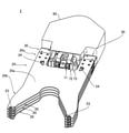
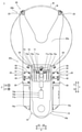
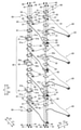
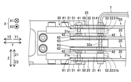
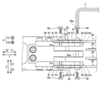
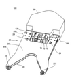
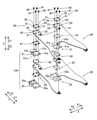
- FIG. 1 shows the structure of the substrate transfer robot by 1st Embodiment of this invention. It is a perspective view which shows the structure of the substrate holding hand by 1st Embodiment of this invention. It is a top view which shows the structure of the substrate holding hand by 1st Embodiment of this invention. It is an exploded perspective view which shows the structure of the blade and the mounting member by 1st Embodiment of this invention. It is a side view for demonstrating the structure of the blade and the mounting member by 1st Embodiment of this invention. It is a side view for demonstrating the removal of the intermediate blade from the attachment member by 1st Embodiment of this invention.
- the board transfer robot 100 includes a board holding hand 1 and an arm 2 for moving the board holding hand 1.
- the substrate holding hand 1 supports a frame 10, a plurality of (four) blades 20 each supporting a substrate (semiconductor wafer) W, and a plurality of blades 20.
- the blade 20 is provided with a mounting member 30 for mounting the blade 20 on the frame 10.
- the plurality (four) blades 20 are arranged so as to be arranged in a direction perpendicular to the main surface 20a of the blade 20 (Z direction), and end portions in a direction perpendicular to the main surface 20a of the blade 20 (Z direction).
- the intermediate blade 20 (2nd or 3rd stage blade 20) is attached to the mounting member 30. It is removable from.
- the plurality of blades 20 attach the blade 20 at the end located at the end in the direction (Z direction) perpendicular to the main surface 20a of the blade 20 to the mounting member 30. Since the intermediate blade 20 can be removed from the mounting member 30 in this state, unlike the case where a plurality of blades 20 need to be removed at once, the blade 20 at the end is mounted on the mounting member 30. Since the intermediate blade 20 can be removed from the mounting member 30, the intermediate blade 20 can be removed from the mounting member 30 while maintaining the level (horizontal state) of the blade 20 at the end, with respect to the intermediate blade 20. Work such as maintenance can be performed.
- the blade 20 at the end has an insertion hole 21 for inserting a fastening member 41 for fastening and fixing the blade 20 at the end to the mounting member 30, and an intermediate blade 20 is mounted.
- a fastening member 42 to be fastened and fixed to the member 30 is inserted, and an insertion hole portion 22 for exposing the fastening member 42 when viewed from a direction (Z direction) perpendicular to the main surface 20a of the blade 20 is included.
- the intermediate blade 20 is a tool (hexagonal) in the hexagonal hole 42a of the head of the fastening member 42 exposed via the insertion hole 22 when viewed from the direction (Z direction) perpendicular to the main surface 20a of the blade 20.
- the blade 20 at the end thereof can be removed from the mounting member 30 in a state of being attached to the mounting member 30 by the fastening member 41.
- the fastening members 41 and 42 are examples of the “first fastening member” and the “second fastening member” in the claims, respectively.
- the insertion hole portions 21 and 22 are examples of the “first insertion hole portion” and the “second insertion hole portion” in the claims, respectively.
- the insertion hole portion 22 has a size into which a tool (hexagonal wrench) T for removing the fastening member 42 can be inserted.
- the insertion hole portion 22 has a size into which the fastening member 42 can be inserted.
- the fastening member 41 is exposed in a state of being inserted into the insertion hole portion 21.
- the blade 20 at the end is removed by inserting a tool (hexagonal wrench) T into the hexagonal hole 41a of the head of the exposed fastening member 41, so that the intermediate blade 20 is attached by the fastening member 42 to the mounting member 30. It can be removed from the mounting member 30 in the state of being mounted on the mounting member 30.
- the mounting member 30 includes a first support portion 31 that supports the blade 20 at the end and a second support portion 32 that supports the blade 20 in the middle.
- the first support portion 31 is arranged at a position overlapping the insertion hole portion 21 in the direction perpendicular to the main surface 20a of the blade 20 (Z direction), and the fastening member 41 inserted through the insertion hole portion 21 is provided.
- the fastening hole portion 31a to be fastened is arranged at a position overlapping the insertion hole portion 22 in the direction perpendicular to the main surface 20a of the blade 20 (Z direction), and the fastening member 42 is inserted together with the insertion hole portion 22. It has an insertion hole portion 31b for the purpose of the insertion.
- the second support portion 32 is arranged at a position overlapping the insertion hole portion 22 and the insertion hole portion 31b in the direction perpendicular to the main surface 20a of the blade 20 (Z direction), and the fastening member 42 is fastened. It has a fastening hole portion 32a.
- the fastening hole portion 31a, the insertion hole portion 31b, and the fastening hole portion 32a are the "first fastening hole portion", the "third insertion hole portion”, and the "second fastening hole portion" in the claims, respectively. Is an example.
- the second support portion 32 commonly supports the intermediate blade 20 adjacent to the blade 20 in the direction perpendicular to the main surface 20a (Z direction).
- the insertion hole portion 21 includes a pair of insertion hole portions 21.
- the insertion hole portion 22 includes a pair of insertion hole portions 22.
- the pair of insertion hole portions 21 and the pair of insertion hole portions 22 are arranged at the corners of a rectangular shape and are arranged on different diagonal lines of the rectangle.
- the substrate holding hand 1 is arranged at a position overlapping the insertion hole portion 21 in a direction perpendicular to the main surface 20a of the blade 20 (Z direction), and also has an insertion hole portion 51 for inserting the fastening member 41.
- the plate 50 is arranged at a position overlapping with the insertion hole portion 22 in the direction perpendicular to the main surface 20a of the blade 20 (Z direction), and includes the insertion hole portion 52 for inserting the fastening member 42. Further prepared.
- the blade 20 at the end is fastened and fixed by the fastening member 41 via the plate 50.
- the plurality of blades 20 attach the blades 20 at the ends to the mounting member 30 on both sides of one side (Z1 direction side) and the other side (Z2 direction side) in the direction (Z direction) perpendicular to the main surface 20a of the blade 20.
- the intermediate blade 20 can be removed from the mounting member 30.
- the intermediate blade 20 is a blade 20 adjacent to the blade 20 at the end in the direction (Z direction) perpendicular to the main surface 20a of the blade 20.
- the arm 2 is a horizontal articulated robot arm.
- the arm 2 includes a first arm 2a and a second arm 2b.
- the first arm 2a is configured to be rotatable with respect to a base 3 described later with one end as a rotation center.
- one end of the first arm 2a is rotatably connected to the base 3 via the first joint.
- the second arm 2b is configured to be rotatable with respect to the first arm 2a with one end as the center of rotation.
- one end of the second arm 2b is rotatably connected to the other end of the first arm 2a via a second joint.
- the substrate holding hand 1 is rotatably connected to the other end of the second arm 2b via a third joint.
- the servomotor which is the drive source for rotational drive
- the rotational position sensor that detects the rotational position of the output shaft of the servomotor
- the output of the servomotor are jointed.
- a drive mechanism including a power transmission mechanism for transmitting to is provided.
- the substrate transfer robot 100 further includes a base 3 to which the arm 2 is attached and an arm elevating mechanism 4 to which the base 3 is attached.
- the base 3 is configured such that one end is connected to one end of the first arm 2a and the other end is connected to the arm elevating mechanism 4.
- the arm elevating mechanism 4 is configured to raise and lower the arm 2 by raising and lowering the base 3.
- the arm elevating mechanism 4 includes a servomotor that is a drive source for elevating and lowering, a rotation position sensor that detects the rotation position of the output shaft of the servomotor, and a power transmission mechanism that transmits the output of the servomotor to the base 3 (arm 2). And include.
- the substrate holding hand 1 is provided with a plurality (4) blades 20. That is, the substrate holding hand 1 is configured to be able to convey (hold) a plurality of (four) substrates W.
- the substrate holding hand 1 includes a frame 10, a blade 20, and a mounting member 30.
- the frame 10 is a support that supports the blade 20.
- the frame 10 includes a pair of side wall portions 10a and a base end portion 10b connecting the pair of side wall portions 10a.
- the pair of side wall portions 10a are provided apart from each other so that the wall surfaces face each other in a direction (X direction) parallel to the direction in which the pair of front support portions 23 described later of the blade 20 are arranged. Further, the pair of side wall portions 10a are provided so as to extend in a direction (Y direction) orthogonal to the direction in which the pair of front support portions 23 are arranged and parallel to the main surface 20a of the blade 20.
- the base end portion 10b connects each base end portion (a portion on the Y2 direction side) of the pair of side wall portions 10a.
- the proximal end portion 10b has a shape that is convexly curved toward the proximal end side (Y2 direction side).
- the pair of side wall portions 10a and the base end portion 10b are provided so as to form a U shape when viewed from the direction (Z direction) perpendicular to the main surface 20a of the blade 20.
- the blade 20 is a thin plate-shaped support plate that supports the substrate W.
- the blade 20 has a front support portion 23 provided on the tip portion 20b side (Y1 direction side) and a rear support portion 24 provided on the base end portion 20c side (Y2 direction side). Further, the blade 20 has a shape in which the tip portion 20b side is bifurcated.
- a pair of front support portions 23 are separately provided for each of the bifurcated portions.
- the pair of front support portions 23 have a plurality of (two) support surfaces provided at different heights from each other.
- the pair of rear support portions 24 have support surfaces provided at substantially the same height as the support surfaces on the lower side (Z2 direction side) of the pair of front support portions 23.
- the "height" means the distance from the main surface 20a of the blade 20 in the direction perpendicular to the main surface 20a of the blade 20 (Z direction).
- the pair of front support portions 23 and the pair of rear support portions 24 are provided on the main surface 20a of the blade 20.
- Each support surface of the pair of front support portions 23 and the pair of rear support portions 24 is configured to support the back surface (the surface on the Z2 direction side) of the outer peripheral edge portion of the substantially circular substrate W from below. ing.
- the blade 20 is provided with an insertion hole portion 21 and an insertion hole portion 22, and further has a fixing portion 25 to be attached to the attachment member 30.
- the fixing portion 25 is provided at the base end portion 20c of the blade 20.
- the fixing portion 25 includes a pair of fixing portions 25.
- the pair of fixing portions 25 are provided on one side (X1 direction side) and the other side (X2 direction side) in the direction (X direction) in which the pair of front support portions 23 are arranged.
- the mounting member 30 includes a pair of mounting members 30 so as to correspond to the pair of fixing portions 25.
- the pair of mounting members 30 are laterally mounted on the side wall portion 10a of the frame 10.
- the mounting member 30 on the X1 direction side is mounted on the portion of the frame 10 on the side wall portion 10a on the X1 direction side on the tip end side from the outside side (X1 direction side).
- the fixing portion 25 on the X1 direction side of the plurality of blades 20 is attached to the mounting member 30 on the X1 direction side.
- the mounting member 30 on the X2 direction side is mounted on the portion of the frame 10 on the side wall portion 10a on the X2 direction side on the tip end side from the outside side (X2 direction side).
- the fixing portion 25 on the X2 direction side of the plurality of blades 20 is attached to the mounting member 30 on the X2 direction side.
- the mounting member 30 is provided with two first support portions 31 and one second support portion 32.
- the first support portion 31 and the second support portion 32 are provided so as to extend from the frame 10 side (Y2 direction side) toward the tip portion 20b side (Y1 direction side) of the blade 20.
- the two first support portions 31 are one side (Z1 direction side) and the other side (Z2 direction side) with respect to the second support portion 32 in the direction (Z direction) perpendicular to the main surface 20a of the blade 20. It is provided in.
- the upper side (Z1 direction side) first support portion 31 supports the blade (first stage blade) 20 at the upper end portion (Z1 direction side) on the upper surface side.
- the lower side (Z2 direction side) first support portion 31 supports the blade (second stage blade) 20 at the end of the lower side (Z2 direction side) on the lower surface side.
- the second support portion 32 supports the intermediate blades (second-stage and third-stage blades) 20 on each of the upper surface side and the lower surface side.
- the middle blade (second stage blade) 20 on the upper side (Z1 direction side) is removed from the mounting member 30, the upper side (Z1 direction side) to the lower side (Z2 direction side).
- the tool T moves toward the insertion hole 22 of the blade (first stage blade) 20 at the upper end (Z1 direction side) and the first support portion 31 on the upper side (Z1 direction side) of the mounting member 30. It is inserted into the insertion hole portion 31b of. Then, the tip end portion of the tool T is inserted into the hexagonal hole 42a of the fastening member 42 in a state of being fastened to the fastening hole portion 32a of the second support portion 32 of the mounting member 30.
- the fastening member 42 Before inserting the tool T into the insertion hole portion 22 and the insertion hole portion 31b, the fastening member 42 passes through the insertion hole portion 22 and the insertion hole portion 31b when viewed from the upper side (Z1 direction side). The head is exposed so that it can be removed by the tool T.
- the fastening member 42 is placed on the lower side (the operation of loosening the fastening member 42 and removing it from the fastening hole portion 32a) via the insertion hole portion 22 and the insertion hole portion 31b. It is removed (taken out) from the Z2 direction side to the upper side (Z1 direction side). Then, in a state where the fastening member 42 releases the fastening and fixing of the intermediate blade 20 on the upper side (Z1 direction side) to the second support portion 32, the intermediate blade 20 on the upper side (Z1 direction side) is released. Moved to be pulled out.
- the procedure is the same when removing the middle blade (third stage blade) 20 on the lower side (Z2 direction side) from the mounting member 30. That is, from the lower side (Z2 direction side) to the upper side (Z1 direction side), the tool T and the insertion hole portion 22 of the blade (fourth stage blade) 20 at the end of the lower side (Z2 direction side). , Is inserted into the insertion hole portion 31b of the first support portion 31 on the lower side (Z2 direction side) of the mounting member 30. Then, the tip end portion of the tool T is inserted into the hexagonal hole 42a of the fastening member 42 in a state of being fastened to the fastening hole portion 32a of the second support portion 32 of the mounting member 30.
- the fastening member 42 Before inserting the tool T into the insertion hole portion 22 and the insertion hole portion 31b, the fastening member 42 passes through the insertion hole portion 22 and the insertion hole portion 31b when viewed from the lower side (Z2 direction side). The head of the head is exposed so that it can be removed by the tool T.
- the fastening member 42 is moved to the upper side (Z1) via the insertion hole portion 22 and the insertion hole portion 31b. It is removed (taken out) from the direction side) to the lower side (Z2 direction side). Then, in a state where the fastening member 42 is released from fastening and fixing the intermediate blade 20 on the lower side (Z2 direction side) to the second support portion 32 of the mounting member 30, the intermediate blade on the lower side (Z2 direction side) is released. 20 is moved so as to be pulled out.
- the blade (fourth stage blade) 20 at the end of the lower side (Z2 direction side) is attached to the first support portion 31 on the lower side (Z2 direction side) of the mounting member 30, the lower side (the lower side (Z2 direction side)).
- the middle blade (third-stage blade) 20 (on the Z2 direction side) is removed from the second support portion 32 of the mounting member 30.
- the second-stage blade 20 and the third-stage blade 20 can be removed independently of each other.
- the substrate holding hand 1 further includes plates 61 to 63 in addition to the plate 50.
- the plate 50 is arranged so as to be sandwiched between the head portion of the fastening member 41 and the blade 20 at the end in a direction perpendicular to the main surface 20a of the blade 20 (Z direction).
- the plate 61 is arranged so as to be sandwiched between the blade 20 at the end and the first support portion 31 of the mounting member 30 in the direction perpendicular to the main surface 20a of the blade 20 (Z direction).
- the plate 62 is arranged so as to be sandwiched between the head of the fastening member 42 and the intermediate blade 20 in the direction perpendicular to the main surface 20a of the blade 20 (Z direction).
- each plate 61 to 63 is provided with an insertion hole portion for inserting the fastening member 41 or 42.
- the substrate holding hand 1 has a movable support unit 71 that moves forward and backward to support the substrate W, and a first movable pressing unit 72 and a first movable pressing unit 72 that moves forward and backward to press the substrate W.
- the movable pressing unit 73 is further provided.
- the movable support unit 71 has a pair of support members 71a that support the substrate W, and an air cylinder 71b as an actuator for moving the pair of support members 71a forward and backward in the Y direction.
- the movable support unit 71 is configured so that a pair of support members 71a can be advanced in the Y1 direction by an air cylinder 71b and arranged at a support position that supports the substrate W.
- the movable support unit 71 is configured so that the pair of support members 71a can be retracted in the Y2 direction by the air cylinder 71b and arranged in a retracted position that does not support the substrate W.
- the pair of support members 71a have support surfaces provided at substantially the same height as the support surface on the upper side (Z1 direction side) of the pair of front support portions 23. Each support surface of the pair of support members 71a is configured to support the back surface (the surface on the Z2 direction side) of the outer peripheral edge portion of the substantially circular substrate W from below.
- the first movable pressing unit 72 has a pair of pressing members 72a for pressing the substrate W and an air cylinder 72b as an actuator for moving the pair of pressing members 72a forward and backward in the Y direction.
- the first movable pressing unit 72 is configured to be able to press the substrate W by advancing the pair of pressing members 72a in the Y1 direction by the air cylinder 72b. Further, the first movable pressing unit 72 is configured so that the pair of pressing members 72a can be retracted in the Y2 direction by the air cylinder 72b and arranged in a retracted position where the substrate W is not pressed.
- the second movable pressing unit 73 has a pair of pressing members 73a that press the substrate W, and an air cylinder 73b as an actuator for moving the pair of pressing members 73a forward and backward in the Y direction.
- the second movable pressing unit 73 is configured to be able to press the substrate W by advancing the pair of pressing members 73a in the Y1 direction by the air cylinder 73b. Further, the second movable pressing unit 73 is configured so that the pair of pressing members 73a can be retracted in the Y2 direction by the air cylinder 73b and arranged in a retracted position where the substrate W is not pressed.
- the support surface on the upper side (Z1 direction side) of the pair of front support portions 23 and the support surface of the pair of support members 71a of the movable support unit 71 are the boards W after processing (after cleaning).
- the pair of pressing members 72a of the first movable pressing unit 72 are supported by the support surface on the upper side (Z1 direction side) of the pair of front support portions 23 and the support surface of the pair of support members 71a of the movable support unit 71.
- the treated substrate W after processing (after cleaning) is pressed.
- the support surface on the lower side (Z2 direction side) of the pair of front support portions 23 and the support surface of the pair of rear support portions 24 support the substrate W before processing (before cleaning). do.
- the pair of pressing members 73a of the second movable pressing unit 73 are supported by the support surface on the lower side (Z2 direction side) of the pair of front support portions 23 and the support surface of the pair of rear support portions 24. Press the substrate W before processing (before cleaning).
- the pair of front support portions 23, the pair of rear support portions 24, the movable support unit 71, the first movable pressing unit 72, and the second movable pressing unit 73 are treated with the substrate W before processing (before cleaning). It can be used properly with the later (after cleaning) substrate W.
- the air cylinder 71b of the movable support unit 71, the air cylinder 72b of the first movable pressing unit 72, and the air cylinder 73b of the second movable pressing unit 73 are arranged inside the frame 10. Further, the air cylinder 71b of the movable support unit 71, the air cylinder 72b of the first movable pressing unit 72, and the air cylinder 73b of the second movable pressing unit 73 are formed on the main surface 20a of the blade 20 inside the frame 10. They are arranged side by side in the vertical direction (Z direction).
- the air cylinder 71b of the movable support unit 71, the air cylinder 72b of the first movable pressing unit 72, and the air cylinder 73b of the second movable pressing unit 73 are in a direction perpendicular to the main surface 20a of the blade 20. It is provided so as to overlap when viewed from (Z direction).
- the air cylinders 71b, 72b and 73b are not arranged side by side in the width direction (X direction) of the frame 10, so that the air cylinders 71b, 72b and 73b can be compactly arranged in the width direction (X direction) of the frame 10. be.
- the substrate holding hand 1 further includes a cover (casing) 80 (see FIG. 2) provided separately from the frame 10.
- the cover 80 is provided so as to cover the frame 10 and a part of the movable support unit 71, the first movable pressing unit 72, and the second movable pressing unit 73 (a portion arranged inside the frame 10).
- the plurality of blades 20 are in the middle in a state where the blade 20 at the end located at the end in the direction perpendicular to the main surface 20a of the blade 20 is attached to the mounting member 30. Since the blade 20 can be removed from the mounting member 30, unlike the case where a plurality of blades 20 need to be removed at once, the intermediate blade 20 is attached to the mounting member 30 at the end of the blade 20. Since it can be removed from the mounting member 30, the intermediate blade 20 can be removed from the mounting member 30 while maintaining the level (horizontal state) of the blade 20 at the end, and maintenance of the intermediate blade 20 can be performed. You can do the work.
- the blade 20 at the end is an insertion hole 21 for inserting the fastening member 41 for fastening and fixing the blade 20 at the end to the mounting member 30, and an intermediate blade.
- a fastening member 42 for fastening and fixing the 20 to the mounting member 30 is inserted, and an insertion hole portion 22 for exposing the fastening member 42 when viewed from a direction perpendicular to the main surface 20a of the blade 20 is included.
- the fastening member 41 is removed by removing the fastening member 42 exposed via the insertion hole portion 22 when viewed from a direction perpendicular to the main surface 20a of the blade 20 via the insertion hole portion 22.
- the blade 20 at the end can be removed from the mounting member 30 in a state of being mounted on the mounting member 30.
- the intermediate blade 20 can be easily removed from the mounting member 30 by simply removing the fastening member 42 via the insertion hole portion 22, so that work such as maintenance on the intermediate blade 20 can be easily performed. can.
- the insertion hole portion 22 has a size in which the tool T for removing the fastening member 42 can be inserted.
- the tool T for removing the fastening member 42 can be easily inserted into the insertion hole portion 22, so that the fastening member 42 can be easily removed by the tool T inserted into the insertion hole portion 22.
- the insertion hole portion 22 has a size into which the fastening member 42 can be inserted.
- the fastening member 42 can be easily inserted into the insertion hole 22 when the intermediate blade 20 is attached to the mounting member 30.
- the fastening member 42 can be easily taken out from the insertion hole portion 22.
- the intermediate blade 20 can be easily attached to the attachment member 30 and the intermediate blade 20 can be easily removed from the attachment member 30.
- the fastening member 41 is exposed in a state of being inserted into the insertion hole portion 21.
- the blade 20 at the end can be removed from the mounting member 30 in a state where the intermediate blade 20 is attached to the mounting member 30 by the fastening member 42 by removing the exposed fastening member 41.
- the blade 20 at the end can be removed from the mounting member 30 with the intermediate blade 20 attached to the mounting member 30, so that the end is maintained at the level (horizontal state) of the intermediate blade 20.
- the blade 20 of the portion can be removed from the mounting member 30, and work such as maintenance of the blade 20 at the end can be performed.
- the mounting member 30 includes a first support portion 31 that supports the blade 20 at the end portion and a second support portion 32 that supports the intermediate blade 20. Further, the first support portion 31 is arranged at a position overlapping with the insertion hole portion 21 in the direction perpendicular to the main surface 20a of the blade 20, and the fastening member 41 inserted through the insertion hole portion 21 is fastened.
- the fastening hole portion 31a is arranged at a position overlapping the insertion hole portion 22 in the direction perpendicular to the main surface 20a of the blade 20, and the insertion hole portion for inserting the fastening member 42 together with the insertion hole portion 22. 31b and.
- the second support portion 32 is arranged at a position overlapping the insertion hole portion 22 and the insertion hole portion 31b in the direction perpendicular to the main surface 20a of the blade 20, and the fastening hole 42 is fastened to the fastening member 42. It has a portion 32a.
- the fastening member 42 can be removed via the insertion hole portion 22 and the insertion hole portion 31b. Therefore, with the blade 20 at the end attached to the first support portion 31 of the attachment member 30, the intermediate blade is attached. 20 can be removed from the second support portion 32 of the mounting member 30.
- the second support portion 32 commonly supports the intermediate blade 20 adjacent to the main surface 20a of the blade 20 in the direction perpendicular to the main surface 20a.
- the support portion for supporting the intermediate blade 20 adjacent to the main surface 20a of the blade 20 is individually provided for each intermediate blade 20
- the support portion for each of the intermediate blades 20 is provided. Since it is not necessary to provide a support portion, the structure of the mounting member 30 can be simplified.
- the insertion hole portion 21 includes a pair of insertion hole portions 21.
- the insertion hole portion 22 includes a pair of insertion hole portions 22.
- the pair of insertion hole portions 21 and the pair of insertion hole portions 22 are arranged at the corners of a rectangular shape and are arranged on different diagonal lines of the rectangle.
- the pair of fastening members 41 corresponding to the pair of insertion hole portions 21 and the pair of fastening members 42 corresponding to the pair of insertion hole portions 22 are arranged at the corners of the rectangular shape, and the rectangular portions are different from each other. Since the blade 20 at the end and the blade 20 at the middle can be fastened and fixed to the mounting member 30 by arranging them diagonally, the blade 20 at the end and the blade 20 at the middle can be fastened and fixed in a well-balanced manner. can.
- the substrate holding hand 1 is arranged at a position overlapping with the insertion hole portion 21 in the direction perpendicular to the main surface 20a of the blade 20, and the fastening member 41 is provided.
- a plate 50 including the above is further provided. Further, the blade 20 at the end is fastened and fixed by the fastening member 41 via the plate 50.
- the blade 20 at the end can be fastened and fixed by the fastening member 41 via the plate 50, so that the force for fastening and fixing the fastening member 41 can be suppressed from being directly applied to the blade 20 at the end. ..
- the fastening member 42 can be removed via the insertion hole 22 and the insertion hole 52, so that the blade at the end can be removed. With the 20 attached to the attachment member 30, the intermediate blade 20 can be removed from the attachment member 30.
- the plurality of blades 20 attach the blades 20 at the ends to the mounting member 30 on one side and both sides in the direction perpendicular to the main surface 20a of the blade 20.
- the intermediate blade 20 can be removed from the mounting member 30.
- the intermediate blade 20 is removed from the mounting member 30 with the blade 20 at the end attached to the mounting member 30 on either one side or the other side in the direction perpendicular to the main surface 20a of the blade 20. Therefore, work such as maintenance on the intermediate blade 20 can be performed more easily.
- the intermediate blade 20 is a blade 20 adjacent to the blade 20 at the end in the direction perpendicular to the main surface 20a of the blade 20.
- the blade 20 adjacent to the blade 20 at the end can be removed from the mounting member 30 with the blade 20 at the end attached to the mounting member 30, so that the level (horizontal state) of the blade 20 at the end can be removed.
- the blade 20 adjacent to the blade 20 at the end can be removed from the mounting member 30 to perform work such as maintenance on the blade 20 adjacent to the blade 20 at the end.
- the substrate holding hand 101 supports a frame 10, a plurality of (two) blades 20 each supporting the substrate W, and a plurality of blades 20, and a plurality of blades 20 are attached to the frame 10. It includes a mounting member 130 for mounting.
- the plurality (two) blades 20 are arranged so that the plurality of blades 20 are arranged in a direction (Z direction) perpendicular to the main surface 20a of the blade 20 and in a direction perpendicular to the main surface 20a of the blade 20 (Z direction).
- the blade 20 at the end (first stage blade 20) located at the end in the Z direction) and the blade 20 adjacent to the blade 20 at the end (second stage blade 20) are formed on the main surface of the blade 20.
- the plurality of blades 20 attach the blade 20 at the end located at the end in the direction (Z direction) perpendicular to the main surface 20a of the blade 20 to the mounting member 130.
- the blade 20 adjacent to the blade 20 at the end can be removed from the mounting member 130, so that the blade 20 at the end is attached to the mounting member, unlike the case where a plurality of blades 20 need to be removed at once. Since the blade 20 adjacent to the blade 20 at the end can be removed from the mounting member 130 while attached to the 130, the blade 20 at the end is maintained at the level (horizontal state) of the blade 20 at the end.
- the blade 20 adjacent to the blade 20 can be removed from the mounting member 130 to perform work such as maintenance on the blade 20 adjacent to the blade 20 at the end.
- the end blade 20 has an insertion hole 21 for inserting a fastening member 41 for fastening and fixing the end blade 20 to the mounting member 130, and a blade adjacent to the end blade 20.
- a fastening member 42 for fastening and fixing the 20 to the mounting member 130 is inserted, and an insertion hole portion 22 for exposing the fastening member 42 when viewed from a direction (Z direction) perpendicular to the main surface 20a of the blade 20 is included.
- the blade 20 adjacent to the blade 20 at the end is a hexagonal hole in the head of the fastening member 42 exposed via the insertion hole 22 when viewed from the direction (Z direction) perpendicular to the main surface 20a of the blade 20.
- the blade 20 at the end can be removed from the mounting member 130 while the blade 20 at the end is attached to the mounting member 130 by the fastening member 41. be.
- the substrate holding hand 101 is provided with a plurality (two) blades 20. That is, the substrate holding hand 101 is configured to be able to convey (hold) a plurality (two) of the substrates W.
- the procedure for removing the blade (second stage blade) 20 adjacent to the end blade (first stage blade) 20 from the mounting member 130 is the same as that of the first embodiment. That is, from the upper side (Z1 direction side) to the lower side (Z2 direction side), the tool T has the insertion hole portion 22 of the blade (first stage blade) 20 at the end and the first support of the mounting member 130. It is inserted into the insertion hole portion 31b of the portion 31. Then, the tip end portion of the tool T is inserted into the hexagonal hole 42a of the fastening member 42 in a state of being fastened to the fastening hole portion 32a of the second support portion 32 of the mounting member 130.
- the fastening member 42 Before inserting the tool T into the insertion hole portion 22 and the insertion hole portion 31b, the fastening member 42 passes through the insertion hole portion 22 and the insertion hole portion 31b when viewed from the upper side (Z1 direction side). The head is exposed so that it can be removed by the tool T.
- the fastening member 42 is placed on the side (the side where the fastening member 42 is inserted through the insertion hole portion 22 and the insertion hole portion 31b. It is removed (taken out) from the Z2 direction side to the upper side (Z1 direction side). Then, the blade 20 adjacent to the blade 20 at the end is pulled out with the fastening member 130 releasing the fastening and fixing of the mounting member 130 adjacent to the blade 20 at the end to the second support portion 32. Will be moved. As a result, with the end blade (first stage blade) 20 attached to the first support portion 31 of the attachment member 130, the blade (second stage blade) 20 adjacent to the end blade 20 is attached. It is removed from the second support portion 32 of the member 130.
- the plurality of blades 20 have end portions in a state where the end blades 20 located at the end portions in the direction perpendicular to the main surface 20a of the blade 20 are attached to the mounting member 130. Since the blade 20 adjacent to the blade 20 can be removed from the mounting member 130, unlike the case where a plurality of blades 20 need to be removed at once, the blade 20 at the end is attached to the mounting member 130. Since the blade 20 adjacent to the blade 20 at the end can be removed from the mounting member 130, the blade 20 adjacent to the blade 20 at the end can be removed while maintaining the level (horizontal state) of the blade 20 at the end. It can be removed from the mounting member 130 to perform work such as maintenance on the blade 20 adjacent to the blade 20 at the end.
- the blade 20 at the end is the insertion hole 21 for inserting the fastening member 41 for fastening and fixing the blade 20 at the end to the mounting member 130, and the blade at the end.
- a fastening member 42 for fastening and fixing the blade 20 adjacent to the blade 20 to the mounting member 130 is inserted, and an insertion hole portion 22 for exposing the fastening member 42 when viewed from a direction perpendicular to the main surface 20a of the blade 20 is included. ..
- the blade 20 adjacent to the blade 20 at the end removes the fastening member 42 exposed via the insertion hole 22 when viewed from a direction perpendicular to the main surface 20a of the blade 20 via the insertion hole 22.
- the blade 20 at the end can be removed from the mounting member 130 with the fastening member 41 attached to the mounting member 130.
- the blade 20 adjacent to the blade 20 at the end can be easily removed from the mounting member 130 simply by removing the fastening member 42 via the insertion hole 22, so that the blade adjacent to the blade 20 at the end can be easily removed. Work such as maintenance for 20 can be easily performed.
- the arm is a horizontal articulated robot arm, but the present invention is not limited to this.
- the arm may be an arm other than the horizontal articulated robot arm such as a vertical articulated robot arm.
- the board holding hand may be provided with a plurality of blades other than four.
- the blade has a bifurcated shape
- the present invention is not limited to this.
- the blade may have a shape other than the bifurcated shape.
- the blades are configured to be able to support two substrates at different heights, but the present invention is not limited to this.
- the blade may be configured to support only one substrate (only one height can support the substrate).
- the example in which the movable support unit is provided is shown, but the present invention is not limited to this.
- the movable support unit may not be provided.
- the movable support unit includes a pair of support members is shown, but the present invention is not limited to this.
- the movable support unit may include one support member.
- first and second embodiments described above an example is shown in which two pressing units, a first movable pressing unit and a second movable pressing unit, are provided, but the present invention is not limited to this.
- only one movable pressing unit may be provided.
- the movable pressing unit includes a pair of pressing members, but the present invention is not limited to this.
- the movable pressing unit may include only one pressing member.
- the intermediate blade is a blade adjacent to the blade at the end (one adjacent blade) in the direction perpendicular to the main surface of the blade
- the present invention has been made.
- the intermediate blade may include a blade adjacent to the blade at the end (one adjacent blade) and two or more adjacent blades in a direction perpendicular to the main surface of the blade. That is, one adjacent blade and two or more adjacent blades are removed from the same side (for example, the upper side) in the direction perpendicular to the main surface of the blade, with the end blade attached to the mounting member. It may be possible.
- the mounting member includes a second support portion that commonly supports an intermediate blade adjacent to the main surface of the blade in a direction perpendicular to the main surface of the blade, but the present invention is limited to this. I can't.
- the mounting member may include a plurality of second supports each supporting an intermediate blade.
- an insertion hole portion for inserting a fastening member (first fastening member) for fastening and fixing the blade at the end portion and an intermediate blade are fastened.
- first insertion hole portion for inserting a fastening member (first fastening member) for fastening and fixing the blade at the end portion and an intermediate blade.
- second insertion holes for inserting a fastening member (second fastening member) to be fixed are provided, but the present invention is limited to this. I can't.
- one or three or more first insertion hole portions (first fastening member) and second insertion hole portions (second fastening member) may be provided.
- the blade at the end is fastened and fixed by a fastening member via a plate
- the present invention is not limited to this.
- the blade at the end may be fastened and fixed by a fastening member without using a plate.
- the intermediate blades are mounted in a state where the plurality of blades have the end blades attached to the mounting member on both sides of one side and the other side in the direction perpendicular to the main surface of the blades.
- An example of being removable from a member has been shown, but the present invention is not limited to this.
- multiple blades can remove the intermediate blade from the mounting member with the end blade attached to the mounting member on either one side or the other side in the direction perpendicular to the main surface of the blade. May be.
Landscapes
- Engineering & Computer Science (AREA)
- Robotics (AREA)
- Mechanical Engineering (AREA)
- Container, Conveyance, Adherence, Positioning, Of Wafer (AREA)
- Manipulator (AREA)
Abstract
Description
図1~図8を参照して、第1実施形態による基板搬送ロボット100の構成について説明する。
第1実施形態では、以下のような効果を得ることができる。
次に、図9および図10を参照して、第2実施形態による基板保持ハンド101の構成について説明する。なお、上記第1実施形態と同一の構成については、図中において同一の符号を付して詳細な説明を省略する。
第2実施形態では、以下のような効果を得ることができる。
なお、今回開示された実施形態は、すべての点で例示であって制限的なものではないと考えられるべきである。本発明の範囲は、上記した実施形態の説明ではなく請求の範囲によって示され、さらに請求の範囲と均等の意味および範囲内でのすべての変更(変形例)が含まれる。
2 アーム
10 フレーム
20 ブレード
20a 主面
21 挿通孔部(第1挿通孔部)
22 挿通孔部(第2挿通孔部)
30、130 取付部材
31 第1支持部
31a 締結孔部(第1締結孔部)
31b 挿通孔部(第3挿通孔部)
32 第2支持部
32a 締結孔部(第2締結孔部)
41 締結部材(第1締結部材)
42 締結部材(第2締結部材)
50 プレート
51 挿通孔部(第4挿通孔部)
52 挿通孔部(第5挿通孔部)
100 基板搬送ロボット
W 基板
Claims (14)
- フレームと、
基板を各々支持する複数のブレードと、
前記複数のブレードを支持するとともに、前記複数のブレードを前記フレームに取り付けるための取付部材と、を備え、
前記複数のブレードは、前記ブレードの主面に垂直な方向に並ぶように配置されており、前記ブレードの主面に垂直な方向における端部に位置する端部の前記ブレードを前記取付部材に取り付けた状態で、中間の前記ブレードを前記取付部材から取り外し可能である、基板保持ハンド。 - 前記端部のブレードは、前記端部のブレードを前記取付部材に締結固定する第1締結部材を挿通するための第1挿通孔部と、前記中間のブレードを前記取付部材に締結固定する第2締結部材を挿通するとともに、前記ブレードの主面に垂直な方向から見て前記第2締結部材を露出するための第2挿通孔部とを含み、
前記中間のブレードは、前記ブレードの主面に垂直な方向から見て前記第2挿通孔部を介して露出している前記第2締結部材を前記第2挿通孔部を介して取り外すことにより、前記第1締結部材により前記端部のブレードを前記取付部材に取り付けた状態で、前記取付部材から取り外し可能である、請求項1に記載の基板保持ハンド。 - 前記第2挿通孔部は、前記第2締結部材を取り外すための工具を挿入可能な大きさを有する、請求項2に記載の基板保持ハンド。
- 前記第2挿通孔部は、前記第2締結部材を挿入可能な大きさを有する、請求項3に記載の基板保持ハンド。
- 前記第1締結部材は、前記第1挿通孔部に挿通した状態で露出しており、
前記端部のブレードは、露出している前記第1締結部材を取り外すことにより、前記第2締結部材により前記中間のブレードを前記取付部材に取り付けた状態で、前記取付部材から取り外し可能である、請求項2に記載の基板保持ハンド。 - 前記取付部材は、前記端部のブレードを支持する第1支持部と、前記中間のブレードを支持する第2支持部と、を含み、
前記第1支持部は、前記ブレードの主面に垂直な方向において前記第1挿通孔部とオーバーラップする位置に配置されているとともに、前記第1挿通孔部に挿通された前記第1締結部材が締結される第1締結孔部と、前記ブレードの主面に垂直な方向において前記第2挿通孔部とオーバーラップする位置に配置されているとともに、前記第2挿通孔部と共に前記第2締結部材を挿通するための第3挿通孔部と、を有し、
前記第2支持部は、前記ブレードの主面に垂直な方向において前記第2挿通孔部および前記第3挿通孔部とオーバーラップする位置に配置されているとともに、前記第2締結部材が締結される第2締結孔部を有する、請求項2に記載の基板保持ハンド。 - 前記第2支持部は、前記ブレードの主面に垂直な方向に隣接する前記中間のブレードを共通に支持する、請求項6に記載の基板保持ハンド。
- 前記第1挿通孔部は、一対の第1挿通孔部を含み、
前記第2挿通孔部は、一対の第2挿通孔部を含み、
前記一対の第1挿通孔部と前記一対の第2挿通孔部とは、矩形状の角部に配置されているとともに、矩形の互いに異なる対角線上に配置されている、請求項2に記載の基板保持ハンド。 - 前記ブレードの主面に垂直な方向において前記第1挿通孔部とオーバーラップする位置に配置されているとともに、前記第1締結部材を挿通するための第4挿通孔部と、前記ブレードの主面に垂直な方向において前記第2挿通孔部とオーバーラップする位置に配置されているとともに、前記第2締結部材を挿通するための第5挿通孔部とを含むプレートをさらに備え、
前記端部のブレードは、前記プレートを介して前記第1締結部材により締結固定されている、請求項2に記載の基板保持ハンド。 - 前記複数のブレードは、前記ブレードの主面に垂直な方向における一方側および他方側の両側において、前記端部のブレードを前記取付部材に取り付けた状態で、前記中間のブレードを前記取付部材から取り外し可能である、請求項1に記載の基板保持ハンド。
- 前記中間のブレードは、前記ブレードの主面に垂直な方向において、前記端部のブレードに隣接するブレードである、請求項1に記載の基板保持ハンド。
- フレームと、
基板を各々支持する複数のブレードと、
前記複数のブレードを支持するとともに、前記複数のブレードを前記フレームに取り付けるための取付部材と、を備え、
前記複数のブレードは、前記ブレードの主面に垂直な方向に並ぶように配置されており、前記ブレードの主面に垂直な方向における端部に位置する端部の前記ブレードと、前記端部のブレードに隣接する前記ブレードとを、前記ブレードの主面に垂直な方向における同一側から取り外し可能であるとともに、前記端部のブレードを前記取付部材に取り付けた状態で、前記端部のブレードに隣接する前記ブレードを前記取付部材から取り外し可能である、基板保持ハンド。 - 前記端部のブレードは、前記端部のブレードを前記取付部材に締結固定する第1締結部材を挿通するための第1挿通孔部と前記端部のブレードに隣接する前記ブレードを前記取付部材に締結固定する第2締結部材を挿通するとともに、前記ブレードの主面に垂直な方向から見て前記第2締結部材を露出するための第2挿通孔部とを含み、
前記端部のブレードに隣接する前記ブレードは、前記ブレードの主面に垂直な方向から見て前記第2挿通孔部を介して露出している前記第2締結部材を前記第2挿通孔部を介して取り外すことにより、前記第1締結部材により前記端部のブレードを前記取付部材に取り付けた状態で、前記取付部材から取り外し可能である、請求項12に記載の基板保持ハンド。 - 基板保持ハンドと、
前記基板保持ハンドを移動させるアームと、を備え、
前記基板保持ハンドは、
フレームと、
基板を各々支持する複数のブレードと、
前記複数のブレードを支持するとともに、前記複数のブレードを前記フレームに取り付けるための取付部材と、を含み、
前記複数のブレードは、前記ブレードの主面に垂直な方向に並ぶように配置されており、前記ブレードの主面に垂直な方向における端部に位置する端部の前記ブレードを前記取付部材に取り付けた状態で、中間の前記ブレードを前記取付部材から取り外し可能である、基板搬送ロボット。
Priority Applications (4)
| Application Number | Priority Date | Filing Date | Title |
|---|---|---|---|
| JP2022546867A JP7518908B2 (ja) | 2020-09-03 | 2020-11-02 | 基板保持ハンドおよび基板搬送ロボット |
| CN202080103709.8A CN116325107B (zh) | 2020-09-03 | 2020-11-02 | 基板保持机械手和基板搬运机器人 |
| KR1020237008329A KR102711575B1 (ko) | 2020-09-03 | 2020-11-02 | 기판 유지 핸드 및 기판 반송 로봇 |
| US18/024,584 US20240025054A1 (en) | 2020-09-03 | 2020-11-02 | Substrate holding hand and substrate conveying robot |
Applications Claiming Priority (2)
| Application Number | Priority Date | Filing Date | Title |
|---|---|---|---|
| JP2020148491 | 2020-09-03 | ||
| JP2020-148491 | 2020-09-03 |
Publications (1)
| Publication Number | Publication Date |
|---|---|
| WO2022049784A1 true WO2022049784A1 (ja) | 2022-03-10 |
Family
ID=80490955
Family Applications (1)
| Application Number | Title | Priority Date | Filing Date |
|---|---|---|---|
| PCT/JP2020/041027 Ceased WO2022049784A1 (ja) | 2020-09-03 | 2020-11-02 | 基板保持ハンドおよび基板搬送ロボット |
Country Status (6)
| Country | Link |
|---|---|
| US (1) | US20240025054A1 (ja) |
| JP (1) | JP7518908B2 (ja) |
| KR (1) | KR102711575B1 (ja) |
| CN (1) | CN116325107B (ja) |
| TW (1) | TWI781473B (ja) |
| WO (1) | WO2022049784A1 (ja) |
Families Citing this family (1)
| Publication number | Priority date | Publication date | Assignee | Title |
|---|---|---|---|---|
| TWI814679B (zh) * | 2023-02-13 | 2023-09-01 | 盛詮科技股份有限公司 | 載板懸浮手臂 |
Citations (5)
| Publication number | Priority date | Publication date | Assignee | Title |
|---|---|---|---|---|
| JPH04113445A (ja) * | 1990-09-04 | 1992-04-14 | Toshiba Corp | 並列計算機 |
| US5907895A (en) * | 1997-03-03 | 1999-06-01 | Taiwan Semiconductor Manufacturing Co., Ltd. | Wafer tweezer assembling device |
| KR20100047532A (ko) * | 2008-10-29 | 2010-05-10 | 주식회사 실트론 | 웨이퍼 이송을 위한 핸드 및 이를 이용한 덤핑로봇 |
| JP2010179420A (ja) * | 2009-02-06 | 2010-08-19 | Nidec Sankyo Corp | 産業用ロボット |
| JP2018161729A (ja) * | 2017-03-27 | 2018-10-18 | 日本電産サンキョー株式会社 | 産業用ロボット |
Family Cites Families (17)
| Publication number | Priority date | Publication date | Assignee | Title |
|---|---|---|---|---|
| US4557657A (en) * | 1983-10-05 | 1985-12-10 | Advanced Semiconductor Materials America, Inc. | Article handling apparatus and method |
| JPH04113445U (ja) * | 1991-03-20 | 1992-10-05 | 株式会社日立製作所 | ウエハ移載装置のウエハ吸着板固定装置 |
| US5697748A (en) * | 1993-07-15 | 1997-12-16 | Applied Materials, Inc. | Wafer tray and ceramic blade for semiconductor processing apparatus |
| EP0634787B1 (en) * | 1993-07-15 | 1997-05-02 | Applied Materials, Inc. | Subsrate tray and ceramic blade for semiconductor processing apparatus |
| US6132165A (en) * | 1998-02-23 | 2000-10-17 | Applied Materials, Inc. | Single drive, dual plane robot |
| JP2006313865A (ja) | 2005-05-09 | 2006-11-16 | Tatsumo Kk | 基板保持装置 |
| JP2007203402A (ja) | 2006-02-01 | 2007-08-16 | Nidec Sankyo Corp | ロボット用ハンドおよび該ハンドを具備する搬送ロボット |
| CN100499063C (zh) * | 2007-01-23 | 2009-06-10 | 友达光电股份有限公司 | 基板定位装置及具有基板定位装置的机台 |
| JP5522596B2 (ja) | 2011-01-25 | 2014-06-18 | 株式会社安川電機 | 吸着装置及びロボットシステム |
| JP5755581B2 (ja) * | 2012-02-13 | 2015-07-29 | 三甲株式会社 | ワーク用支持部材 |
| CN202662653U (zh) * | 2012-04-23 | 2013-01-09 | 江苏爱多光伏科技有限公司 | 一种太阳能硅片切片机用线轴上料车 |
| JP6184667B2 (ja) * | 2012-07-26 | 2017-08-23 | 日置電機株式会社 | プローブユニット、基板検査装置およびプローブユニット製造方法 |
| CN103453872A (zh) * | 2013-08-02 | 2013-12-18 | 上海交通大学 | 多轴真空机械手轴系精度测试装置 |
| JP2015089583A (ja) | 2013-11-05 | 2015-05-11 | キヤノン株式会社 | ロボット装置 |
| JP6738740B2 (ja) * | 2015-01-24 | 2020-08-12 | 立川ブラインド工業株式会社 | 横型ブラインド |
| JP6690213B2 (ja) | 2015-12-09 | 2020-04-28 | セイコーエプソン株式会社 | ロボット、制御装置およびロボットシステム |
| JP7255205B2 (ja) | 2019-01-30 | 2023-04-11 | セイコーエプソン株式会社 | ロボットシステムおよびロボット制御装置 |
-
2020
- 2020-11-02 TW TW109138067A patent/TWI781473B/zh active
- 2020-11-02 JP JP2022546867A patent/JP7518908B2/ja active Active
- 2020-11-02 KR KR1020237008329A patent/KR102711575B1/ko active Active
- 2020-11-02 US US18/024,584 patent/US20240025054A1/en active Pending
- 2020-11-02 CN CN202080103709.8A patent/CN116325107B/zh active Active
- 2020-11-02 WO PCT/JP2020/041027 patent/WO2022049784A1/ja not_active Ceased
Patent Citations (5)
| Publication number | Priority date | Publication date | Assignee | Title |
|---|---|---|---|---|
| JPH04113445A (ja) * | 1990-09-04 | 1992-04-14 | Toshiba Corp | 並列計算機 |
| US5907895A (en) * | 1997-03-03 | 1999-06-01 | Taiwan Semiconductor Manufacturing Co., Ltd. | Wafer tweezer assembling device |
| KR20100047532A (ko) * | 2008-10-29 | 2010-05-10 | 주식회사 실트론 | 웨이퍼 이송을 위한 핸드 및 이를 이용한 덤핑로봇 |
| JP2010179420A (ja) * | 2009-02-06 | 2010-08-19 | Nidec Sankyo Corp | 産業用ロボット |
| JP2018161729A (ja) * | 2017-03-27 | 2018-10-18 | 日本電産サンキョー株式会社 | 産業用ロボット |
Also Published As
| Publication number | Publication date |
|---|---|
| KR102711575B1 (ko) | 2024-09-27 |
| CN116325107B (zh) | 2025-06-17 |
| JPWO2022049784A1 (ja) | 2022-03-10 |
| TWI781473B (zh) | 2022-10-21 |
| US20240025054A1 (en) | 2024-01-25 |
| TW202211355A (zh) | 2022-03-16 |
| CN116325107A (zh) | 2023-06-23 |
| KR20230048540A (ko) | 2023-04-11 |
| JP7518908B2 (ja) | 2024-07-18 |
Similar Documents
| Publication | Publication Date | Title |
|---|---|---|
| TWI500491B (zh) | 機械手及機械人 | |
| CN111055303A (zh) | 夹持工具以及利用该工具的改进的分拣系统 | |
| CN102105375A (zh) | 板状工件的移送设备及移送方法 | |
| JPWO2009034795A1 (ja) | 基板搬送ロボット、真空処理装置 | |
| WO2020241900A1 (ja) | 基板組立装置及び基板組立方法 | |
| JP5442226B2 (ja) | 基板処理装置 | |
| JP7518908B2 (ja) | 基板保持ハンドおよび基板搬送ロボット | |
| TWI755135B (zh) | 基板保持手及基板搬送機器人 | |
| JP4394797B2 (ja) | 基板搬送装置 | |
| TW201834801A (zh) | 機器人之教示方法 | |
| WO2022049786A1 (ja) | 基板保持ハンドおよび基板搬送ロボット | |
| JP7568729B2 (ja) | 基板保持ハンドおよび基板搬送ロボット | |
| CN111421676A (zh) | 端材去除装置 | |
| WO2022049783A1 (ja) | 基板保持ハンドおよび基板搬送ロボット | |
| TWI779382B (zh) | 基板保持手及基板搬送機器人 | |
| JPH06349933A (ja) | ウエハ移載装置 | |
| JP4569549B2 (ja) | 移載装置 | |
| HK40116847A (en) | Electron beam lithography (ebl) cooperative manipulator | |
| HK40116847B (en) | Electron beam lithography (ebl) cooperative manipulator | |
| JP2005026290A (ja) | ワーク受取装置およびそれを備えてなるロボット | |
| JP2000340634A (ja) | ワーク搬送装置 | |
| JPH10253683A (ja) | 基板の検査装置 |
Legal Events
| Date | Code | Title | Description |
|---|---|---|---|
| 121 | Ep: the epo has been informed by wipo that ep was designated in this application |
Ref document number: 20952518 Country of ref document: EP Kind code of ref document: A1 |
|
| ENP | Entry into the national phase |
Ref document number: 2022546867 Country of ref document: JP Kind code of ref document: A |
|
| WWE | Wipo information: entry into national phase |
Ref document number: 18024584 Country of ref document: US |
|
| ENP | Entry into the national phase |
Ref document number: 20237008329 Country of ref document: KR Kind code of ref document: A |
|
| NENP | Non-entry into the national phase |
Ref country code: DE |
|
| 122 | Ep: pct application non-entry in european phase |
Ref document number: 20952518 Country of ref document: EP Kind code of ref document: A1 |
|
| WWG | Wipo information: grant in national office |
Ref document number: 202080103709.8 Country of ref document: CN |