WO2022044744A1 - 手摺ベルト、乗客コンベアの移動手摺及び乗客コンベアの移動手摺の製造方法 - Google Patents
手摺ベルト、乗客コンベアの移動手摺及び乗客コンベアの移動手摺の製造方法 Download PDFInfo
- Publication number
- WO2022044744A1 WO2022044744A1 PCT/JP2021/029011 JP2021029011W WO2022044744A1 WO 2022044744 A1 WO2022044744 A1 WO 2022044744A1 JP 2021029011 W JP2021029011 W JP 2021029011W WO 2022044744 A1 WO2022044744 A1 WO 2022044744A1
- Authority
- WO
- WIPO (PCT)
- Prior art keywords
- handrail
- handrail belt
- passenger conveyor
- belt
- moving handrail
- Prior art date
- Legal status (The legal status is an assumption and is not a legal conclusion. Google has not performed a legal analysis and makes no representation as to the accuracy of the status listed.)
- Ceased
Links
Images







Classifications
-
- B—PERFORMING OPERATIONS; TRANSPORTING
- B66—HOISTING; LIFTING; HAULING
- B66B—ELEVATORS; ESCALATORS OR MOVING WALKWAYS
- B66B23/00—Component parts of escalators or moving walkways
- B66B23/22—Balustrades
- B66B23/24—Handrails
Definitions
- Patent Document 1 discloses a moving handrail of a passenger conveyor and a method for manufacturing the same. According to the manufacturing method, a marker representing a pattern is attached to a moving handrail of a passenger conveyor using an adhesive.
- Patent Document 1 the pattern described in Patent Document 1 is provided by attaching the material to the moving handrail. This requires additional material to form the pattern.
- An object of the present disclosure is to provide a handrail belt, a moving handrail of a passenger conveyor, and a method of manufacturing the same, which can reduce the material for forming a pattern.
- the handrail belt according to the present disclosure is a handrail belt used for a moving handrail of a passenger conveyor, and is provided on the wear-resistant body formed in a band shape and the wear-resistant body along the longitudinal direction of the wear-resistant body.
- a core body having a recessed patterned groove on a surface not in contact with the wear-resistant body, and a tension body provided inside the core body along the longitudinal direction of the core body were provided.
- the moving handrail of the passenger conveyor according to the present disclosure is formed in an endless shape, and is arranged along the longitudinal direction of the wear-resistant body and the wear-resistant body arranged above the balustrade of the passenger conveyor so as to face the upper surface of the balustrade.
- a wear-resistant body formed in an endless shape and arranged above the balustrade of the passenger conveyor so as to face the upper surface of the balustrade, and a wear-resistant body provided on the wear-resistant body along the longitudinal direction of the wear-resistant body.
- the method for manufacturing a moving handrail of a passenger conveyor is an extrusion molding step of extruding a handrail belt having thermoplasticity in a softened state, and a cooling step performed after the extrusion molding step to cool the handrail belt. And, a cutting step performed after the cooling step to adjust the length in the longitudinal direction of the handrail belt by cutting the handrail belt, and a cutting step performed after the cutting step, both ends of the handrail belt.
- a method for manufacturing a moving handrail of a passenger conveyor comprising a joining step of joining by heating a portion to produce an endless moving handrail, which is performed after the extrusion molding step and is in a softened state. Further provided is a transfer step of forming a recessed pattern in the shape of the first projecting body on the handrail belt by pressing the first projecting body against the surface of the handrail belt.
- the method for manufacturing a moving handrail of a passenger conveyor includes an extrusion molding step of extruding a handrail belt having thermoplasticity, a cooling step of cooling the handrail belt after the extrusion molding step, and the cooling.
- An extrusion molding step of extruding a handrail belt having thermoplasticity in a softened state, a cooling step performed after the extrusion molding step to cool the handrail belt, and a cooling step performed after the cooling step are performed to obtain the handrail belt.
- a method for manufacturing a moving handrail of a passenger conveyor comprising: By pressing the first projecting body supplied with a coloring material having a color different from that of the above, the handrail belt is formed by being recessed in the shape of the first projecting body, and the bottom surface is colored in the color of the coloring material.
- a method for manufacturing a moving handrail of a passenger conveyor comprising a step, wherein the joining step is the color of the surface of the handrail belt with respect to both ends of the handrail belt in a heated and softened state.
- the moving handrail of the passenger conveyor is provided on the wear-resistant body along the longitudinal direction of the wear-resistant body, and is provided with a core body having a concave patterned groove on the upward facing surface above the balustrade. Therefore, the material for forming the pattern can be reduced.
- FIG. 5 is a cross-sectional view showing an overall configuration of a passenger conveyor to which the moving handrail of the passenger conveyor according to the first embodiment is applied. It is a perspective view of the moving handrail of a passenger conveyor in Embodiment 1. FIG. It is sectional drawing of the moving handrail of a passenger conveyor and the guide of the upper part of a balustrade in Embodiment 1. FIG. It is a perspective view of the main part of the moving handrail of a passenger conveyor in Embodiment 1. FIG. It is a flowchart which shows the manufacturing method of the moving handrail of a passenger conveyor in Embodiment 1.
- FIG. 1 It is a schematic diagram which showed from the extrusion molding process to the cooling process of the manufacturing method of the moving handrail of a passenger conveyor in Embodiment 1. It is sectional drawing of the transfer apparatus and the handrail belt used in the manufacturing method of the moving handrail of a passenger conveyor in Embodiment 1.
- FIG. It is a perspective view of the transfer apparatus which showed the transfer process of the manufacturing method of the moving handrail of a passenger conveyor in Embodiment 1.
- FIG. It is a perspective view of the main part of the handrail belt which carried out the end processing process of the manufacturing method of the moving handrail of a passenger conveyor in Embodiment 1.
- FIG. It is sectional drawing of the press apparatus used for manufacturing the moving handrail of a passenger conveyor in Embodiment 1.
- FIG. 3 is a perspective view of an upper die of a press device used for manufacturing a moving handrail of a passenger conveyor according to the first embodiment. It is a schematic diagram of the inside of the press apparatus which showed the material replenishing process and the joining process of the manufacturing method of the moving handrail of a passenger conveyor in Embodiment 1.
- FIG. It is a perspective view of the main part of the moving handrail of a passenger conveyor in Embodiment 1.
- FIG. It is a perspective view of the main part of the moving handrail of a passenger conveyor in Embodiment 2.
- FIG. It is a schematic diagram which showed from the extrusion molding process to the cooling process of the manufacturing method of the moving handrail of a passenger conveyor in Embodiment 2.
- FIG. 1 It is a perspective view of the transfer apparatus and the coloring unit which showed the transfer process of the manufacturing method of the moving handrail of a passenger conveyor in Embodiment 2.
- FIG. It is a schematic diagram of the inside of the press apparatus which showed the joining process of the manufacturing method of the moving handrail of a passenger conveyor in Embodiment 2.
- FIG. 1 It is a schematic diagram of the inside of the press apparatus which showed the joining process of the manufacturing method of the moving handrail of a passenger conveyor in Embodiment 2.
- FIG. 1 is a cross-sectional view showing an overall configuration of a passenger conveyor to which the moving handrail of the passenger conveyor according to the first embodiment is applied.
- the passenger conveyor 1 in FIG. 1 is an escalator.
- the passenger conveyor 1 is laid between the upper floor and the lower floor of a building (not shown).
- the first entrance 2a is provided on the upper floor of the building.
- the second entrance 2b is provided on the lower floor of the building.
- the plurality of steps 3 are provided between the first entrance / exit 2a and the second entrance / exit 2b.
- the plurality of steps 3 are connected in a ring shape.
- the plurality of steps 3 are provided so as to circulate between the first entrance / exit 2a and the second entrance / exit 2b.
- the main frame 4 is hung between the first entrance / exit 2a and the second entrance / exit 2b.
- the main frame 4 includes a machine room 4a.
- the machine room 4a is provided below the first entrance / exit 2a.
- the balustrade 6 is provided between the first boarding / alighting port 2a and the second boarding / alighting port 2b.
- the balustrade 6 is provided on the upper side of the main frame 4.
- the balustrade 6 is provided on both sides of the plurality of steps 3.
- the balustrade 6 includes a guide 6a.
- the guide 6a is provided at the edge of the balustrade 6.
- the handrail drive device 7 is provided below the balustrade 6.
- the handrail drive device 7 is driven by the electric motor 5.
- the moving handrail 10 is formed in an endless shape.
- the moving handrail 10 is provided around the balustrade 6 along the guide 6a of the balustrade 6.
- the moving handrail 10 is driven by the handrail drive device 7.
- the moving handrail 10 circulates around the balustrade 6.
- FIG. 2 is a perspective view of a moving handrail of a passenger conveyor according to the first embodiment.
- the moving handrail 10 is a member in which both end portions of the band-shaped handrail belt 100 are joined.
- the moving handrail 10 is composed of a joint portion 101 and a non-joint portion 102.
- the joint portion 101 is a portion of the moving handrail 10 where both end portions of the handrail belt 100 are joined.
- the reinforcing material 101a is attached to the moving handrail 10.
- the reinforcing material 101a is a canvas. The reinforcing material 101a suppresses the moving handrail 10 from being cut at the joint portion 101.
- the non-joint portion 102 is a portion of the moving handrail 10 excluding the joint portion 101.
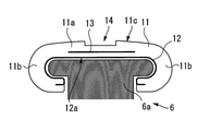
- FIG. 3 is a cross-sectional view of the moving handrail of the passenger conveyor and the guide on the upper part of the balustrade according to the first embodiment.
- the moving handrail 10 includes a core body 11, a wear-resistant body 12, a tension body 13, and a plurality of patterned grooves 14.
- the core 11 has thermoplasticity.
- the material of the core 11 is a resin having thermoplasticity.
- the resin having thermoplasticity is a single thermoplastic resin such as polyurethane-based, polyolefin-based, polystyrene-based, or a thermoplastic resin in which two or more of these are mixed.
- the cross-sectional shape of the core 11 is C-shaped.
- the core body 11 is endless.
- the main portion 11a is a flat portion of the core body 11.
- the main portion 11a is formed in a band shape along the longitudinal direction of the core body 11.
- the main portion 11a is located above the guide 6a.
- the main portion 11a has a design surface 11c.
- the pair of curved portions 11b are curved portions of the core body 11.
- the pair of curved portions 11b are formed on both sides of the main portion 11a in the cross section of the core body 11.
- each of the pair of curved portions 11b is located laterally and downwardly of the guide 6a.
- the wear resistant body 12 is a cloth.
- the material of the cloth of the wear-resistant body 12 is a natural fiber, a synthetic fiber, or a fiber in which a natural fiber and a synthetic fiber are mixed, and the like.
- the natural fibers are cotton, hemp, and the like.
- Synthetic fibers are polyester, etc.
- the wear-resistant body 12 is provided over the entire length of the moving handrail 10.
- the wear resistant body 12 is endless.
- the wear-resistant body 12 is provided on the surface of the core body 11 inside the C-shaped curved inside of the core body 11.
- the tension body 13 is a metal plate.
- the tension body 13 is provided inside the core body 11.
- the tension body 13 is provided on the main portion 11a of the core body 11.
- the tension body 13 is located between the design surface 11c and the wear resistant body 12.
- the tension body 13 is provided along the longitudinal direction of the moving handrail 10.
- the tension body 13 is provided over the entire length of the moving handrail 10.
- the tension body 13 improves the tensile strength of the moving handrail 10 in the longitudinal direction.
- the tension body 13 improves the bending strength of the moving handrail 10 in the longitudinal direction.
- the pattern groove 14 is a groove in which the design surface 11c is recessed in the main portion 11a of the core body 11.
- the distance from the design surface 11c to the bottom surface of the pattern groove 14 is shorter than the distance from the design surface 11c to the tension body 13.
- the distance from the design surface 11c to the bottom surface of the pattern groove 14 is 10 mm or less.
- the plurality of pattern grooves 14 are arranged along the longitudinal direction of the moving handrail 10.
- the plurality of pattern grooves 14 are provided over the entire length of the moving handrail 10.
- the plurality of pattern grooves 14 are arranged at the same spacing between the joint portion 101 (not shown in FIG. 4), the non-joint portion 102 (not shown in FIG. 4), and the joint portion 101 and the non-joint portion 102.
- the shape of the pattern groove 14 is the shape of an arrow.
- the plurality of pattern grooves 14 all have the same shape.
- the length of the pattern groove 14 is less than half the length of the joint portion 101.
- the length of the pattern groove 14 is equal to or less than the length of the main portion 11a of the core body 11.
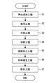
- FIG. 5 is a flowchart showing a method of manufacturing a moving handrail of a passenger conveyor according to the first embodiment.
- step S2 the transfer step is performed.
- the transfer step is a step of providing the pattern groove 14 on the handrail belt 100.
- step S3 a cooling step is performed.
- the cooling step is a step of cooling the handrail belt 100.
- the cutting step is a step of cutting continuously connected handrail belts 100 to an arbitrary length.
- the length of the handrail belt 100 becomes a length corresponding to the final specifications of the moving handrail 10.
- step S5 the end processing step is performed.
- the end processing step is a step of cutting the core 11 at the ends on both sides of the handrail belt 100.
- step S6 the material replenishment step is performed.
- the material replenishment step is a step of arranging a material having thermoplasticity at both end portions of the handrail belt 100.
- step S7 the joining step is performed.
- the joining step is a step of manufacturing the moving handrail 10 from the handrail belt 100. In the joining process, both ends of the handrail belt 100 are joined to each other. In the joining step, the pattern groove 14 is provided in the joining portion 101 of the moving handrail 10.
- FIG. 6 is a schematic view showing from the extrusion molding step to the cooling step of the method for manufacturing a moving handrail of a passenger conveyor in the first embodiment.
- the extruder 20 is used in the extrusion molding process.
- the extruder 20 heats the material of the core 11 (not shown).
- the extruder 20 melts the material of the core 11.
- the extruder 20 discharges the molten core 11 material while applying pressure.
- the cooling device 22 is used in the cooling process.
- the cooling device 22 is adjacent to the extrusion mold of the mold 21.
- the cooling device 22 sprays the refrigerant into the inside.
- the refrigerant is air, water, or the like.
- the transfer device 30 is used in the transfer process.
- the transfer device 30 is provided between the mold 21 and the cooling device 22.
- the transfer device 30 is provided above the handrail belt 100.
- the transfer device 30 provides the handrail belt 100 with a pattern groove 14.
- the material of the wear resistant body 12 and the material of the tensile strength body 13 are continuously supplied to the mold 21 from the direction indicated by the arrow A.
- the extruder 20 continuously supplies the molten core 11 material to the mold 21.
- the material of the molten core body 11, the material of the wear-resistant body 12, and the material of the tensile strength body 13 are arranged inside the formwork 21 at positions corresponding to the cross section of the handrail belt 100.
- the extruder 20 applies pressure to the inside of the mold 21 by using the material of the molten core 11.
- the handrail belt 100 is extruded from the extrusion mold of the mold 21 by the pressure applied to the inside of the mold 21 by the extruder 20.
- the handrail belt 100 is extruded so that the design surface 11c faces upward.
- the handrail belt 100 is continuously extruded in the extrusion direction.
- the handrail belt 100 is extruded in a relatively high temperature state. Therefore, the handrail belt 100 is extruded in a state where the surface is softened.
- the pattern groove 14 is provided on the handrail belt 100 in a state of being softened by the transfer device 30.
- the handrail belt 100 moves inside the cooling device 22.
- the cooling device 22 sprays the refrigerant on the handrail belt 100.
- the handrail belt 100 is cooled.
- the handrail belt 100 changes from a softened state to a hardened state.
- the molding of the handrail belt 100 is completed.
- FIG. 7 is a cross-sectional view of a handrail belt and a transfer device used in the transfer step of the method for manufacturing a moving handrail of a passenger conveyor according to the first embodiment.
- a cross section of the handrail belt 100 and a cross section of the transfer device based on the cross section are shown.
- the transfer device 30 includes a transfer body 31, a plurality of first projecting bodies 32, and a rotating body 33.
- the material of the transfer body 31 is a material that does not easily undergo thermal deformation.
- the material of the transfer body 31 is metal.
- the shape of the transfer body 31 is a shape in which the side surface of the cylinder is recessed.
- the transfer body 31 is arranged above the handrail belt 100.
- the transfer body 31 is rotatably provided.
- the rotation axis of the transfer body 31 is the central axis of the cylinder of the transfer body 31.
- the tangential direction of rotation of the transfer body 31 is the extrusion direction.
- the transfer body 31 includes a transfer surface 31a.
- the transfer surface 31a is the surface of a recessed region on the side surface of the transfer body 31.
- the transfer surface 31a is formed around the side surface of the transfer body 31.
- the shape of the transfer surface 31a is equal to the shape of the upper part of the handrail belt 100.
- the transfer surface 31a is in contact with the design surface 11c of the handrail belt 100.
- the first projecting body 32 projects with respect to the transfer surface 31a.
- the first projecting body 32 has the shape of an arrow.
- the plurality of first projecting bodies 32 are arranged so as to go around the side surface of the transfer body 31.
- the rotating body 33 is a bearing.
- the rotating body 33 is provided inside the transfer body 31.
- the rotating body 33 is provided along the central axis of the transfer body 31.
- the rotating body 33 rotatably supports the transfer body 31.
- FIG. 8 is a perspective view of a transfer device showing a transfer process of the method for manufacturing a moving handrail of a passenger conveyor according to the first embodiment.
- the rotating body 33 is given a force in the direction of the handrail belt 100.
- the rotating body 33 presses the transfer body 31 against the design surface 11c of the handrail belt 100.
- the machined groove 50 is a groove formed by cutting the core body 11.
- the machined grooves 50 are provided at both ends of the handrail belt 100.
- the machined groove 50 is provided in the main portion 11a of the core body 11.
- the length of the machined groove 50 is longer than the length of the pattern groove 14. In the width direction of the handrail belt 100, the length of the machined groove 50 is longer than the length of the pattern groove 14. The distance from the design surface 11c to the bottom surface of the machined groove 50 is longer than the distance from the design surface 11c to the bottom surface of the pattern groove 14. The distance from the design surface 11c to the machined groove 50 is shorter than the distance from the design surface 11c to the tension body 13.
- FIG. 10 is a cross-sectional view of a press device used for manufacturing a moving handrail of a passenger conveyor according to the first embodiment.
- the press device 60 is used in the material replenishment step and the joining step.
- the press device 60 includes a lower die 61 and an upper die 62.
- the lower mold 61 is a mold.
- the upper mold 62 is a mold.
- the upper mold 62 is provided above the lower mold 61.
- the upper mold 62 fits into the lower mold 61.
- the push surface 62a of the upper die 62 faces the lower die 61.
- the upper mold 62 is provided so as to be able to move up and down with respect to the lower mold 61.
- FIG. 11 is a perspective view of a main part of an upper die of a press device used for manufacturing a moving handrail of a passenger conveyor according to the first embodiment.
- the upper die 62 includes a plurality of second projecting bodies 63 on the push surface 62a.
- the second projecting body 63 projects with respect to the pushing surface 62a.
- the second projecting body 63 has the same shape as the first projecting body 32 (not shown in FIG. 11).
- each of the plurality of second protrusions 63 is in the shape of an arrow.
- the plurality of second projecting bodies 63 are arranged in the center of the push surface 62a.
- both end portions of the handrail belt 100 are arranged in the press device 60.
- the end faces on both sides of the handrail belt 100 are in contact with each other.
- the machined groove 50 faces upward.
- the tension bodies 13 are arranged so as not to overlap each other.
- the replenishment material 70 is arranged so as to cover the processing groove 50.
- the replenisher 70 has thermoplasticity.
- the material of the replenisher 70 is the same as the material of the core 11.
- the amount of the replenisher 70 is equal to or greater than the amount of the core 11 scraped off in the end processing step.
- the press device 60 heats the lower mold 61 and the upper mold 62.
- the press device 60 presses the upper mold 62 against the lower mold 61.
- the lower mold 61 and the upper mold 62 sandwich the ends on both sides of the handrail belt 100 in the mold portion 60a (not shown in FIG. 12).
- the lower mold 61 and the upper mold 62 apply pressure to both end portions of the handrail belt 100 in the mold portion 60a. Both ends of the handrail belt 100 are heated. Both ends of the handrail belt 100 are melted or softened.
- the ends on both sides of the melted handrail belt 100 are integrally molded.
- the ends on both sides of the handrail belt 100 are joined in the mold portion 60a.
- the second projecting body 63 When the ends on both sides of the handrail belt 100 are joined, the second projecting body 63 is pressed against the ends on both sides of the handrail belt 100 in a softened state.
- the second projecting body 63 is provided with a pattern groove 14 (not shown in FIG. 12) on the design surface 11c of the handrail belt 100.
- the handrail belt 100 includes a core body 11, a wear resistant body 12, and a tension body 13.
- the wear-resistant body 12 has a band shape.
- the pattern groove 14 is provided on the surface of the core body 11 where the wear resistant body 12 does not come into contact.
- the pattern groove 14 is formed by denting from the surface. Therefore, the handrail belt 100 can be provided with a pattern without using additional material.
- the moving handrail 10 includes a core body 11, a wear resistant body 12, and a tension body 13.
- the wear-resistant body 12 faces the guide 6a, which is the upper surface of the balustrade 6, above the balustrade 6.
- the pattern groove 14 is formed by denting the design surface 11c. Therefore, the moving handrail 10 can be provided with a pattern without using additional material.
- the additional material is a sealing material, an adhesive, and the like. As a result, the material for forming the pattern can be reduced.
- the second projecting body 63 is pressed against the softened joining portion 101. Therefore, in the existing joining process, the pattern groove 14 can be provided on the handrail belt 100.
- the method for manufacturing the moving handrail 10 includes a transfer step and a joining step.
- the press device 60 provides the handrail belt 100 with the pattern groove 14. Therefore, the pattern groove 14 can be provided in the joint portion 101 and the non-joint portion 102 of the moving handrail 10.
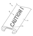
- FIG. 13 is a perspective view of a main part of a moving handrail of a passenger conveyor according to the first embodiment.
- the upper mold 62 (not shown in FIG. 13) includes a plurality of second protrusions 63 (not shown in FIG. 13) corresponding to the pattern groove 15.
- the plurality of second projecting bodies 63 corresponding to the pattern groove 15 are arranged in the center of the push surface 62a (not shown in FIG. 13).
- the length of the upper die 62 in the extrusion direction is longer than the total length of the plurality of second protrusions 63 arranged side by side.
- the passenger conveyor shown in FIG. 1 is an example, and does not specify the model of the passenger conveyor to which the moving handrail 10 of the first embodiment is applied. Further, the passenger conveyor 1 is not limited to the escalator. For example, the moving walkway 10 is applied to a moving walkway.
- the tension body 13 is not limited to the metal plate.
- the tension body 13 is a plurality of steel wires.
- the tension body 13 is a wire rod obtained by twisting a plurality of steel wires.
- the formwork 21 may extrude the handrail belt 100 so that the design surface 11c faces downward.
- the transfer device 30 is provided below the handrail belt 100.
- the transfer step may be performed during the cooling step.
- the transfer device 30 may be provided inside the cooling device 22.
- the rotating body 33 does not have to be a bearing as long as it rotatably supports the transfer body 31.
- the rotating body 33 is a rotating shaft of a motor.
- the rotating body 33 rotates the transfer body 31 by using the power of the motor.
- the transfer device 30 has a temperature control function.
- the temperature control function of the transfer device 30 changes the temperature of the transfer body 31.
- the transfer device 30 detects the surface temperature of the handrail belt 100 before passing through the transfer body 31.
- a heater or the like capable of controlling the temperature of the transfer body 31 is incorporated in the transfer body 31. The heater appropriately adjusts the difference between the surface temperature of the handrail belt 100 and the surface temperature of the transfer body 31 as a temperature control function.
- the core body 11 scraped off in the end processing step may be used as the replenishment material 70.
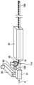
- FIG. 14 is a perspective view of a main part of a moving handrail of a passenger conveyor according to a second embodiment.
- the same or corresponding parts as those of the first embodiment are designated by the same reference numerals. The explanation of this part is omitted.
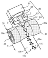
- the moving handrail 10 includes a plurality of colored pattern grooves 16 instead of the plurality of pattern grooves 14 in the first embodiment.
- FIG. 15 is a schematic view showing from the extrusion molding step to the cooling step of the method for manufacturing a moving handrail of a passenger conveyor in the second embodiment.
- the first projecting body 32 (not shown in FIG. 15) of the transfer device 30 comes into contact with the coloring unit 80 and then is pressed against the handrail belt 100.
- the coloring material 16a is supplied to the surface of the first projecting body 32.
- the first projecting body 32 is pressed against the softened handrail belt 100 to provide the handrail belt 100 with the colored pattern groove 16. In this way, the bottom surface of the colored pattern groove 16 is colored in the same color as the coloring material 16a.
- FIG. 16 is a perspective view of a transfer device and a coloring unit showing a transfer process of a method for manufacturing a moving handrail of a passenger conveyor according to a second embodiment.
- the coloring unit 80 includes a pressurizing device 81, a pair of arms 82, a rotating shaft 83, and a coloring roll 84.
- the colored roll 84 is rotatably provided on the rotation shaft 83 so that the cylindrical central axis coincides with the rotation shaft 83.
- the outer peripheral surface of the colored roll 84 is adjacent to the transfer surface 31a of the transfer body 31 and the first projecting body 32.
- the pressurizing device 81 moves the coloring roll 84 to the first position and the second position by adjusting the length of the pair of arms 82 extending from the pressurizing device 81.
- the colored roll 84 does not come into contact with the transfer body 31 at the first position.
- the colored roll 84 is in contact with the first projecting body 32 in the transfer body 31 at the second position.
- the pressurizing device 81 presses the colored roll 84 against each of the plurality of first protrusions 32 with a constant pressure in the direction of the arrow C.
- the coloring roll 84 supplies the coloring material 16a to the surfaces of the plurality of first protrusions 32 at the second position.
- FIG. 17 is a schematic view of the inside of a press device showing a joining process of a method for manufacturing a moving handrail of a passenger conveyor according to a second embodiment.
- the joining coloring unit 90 is used in the joining step of the second embodiment.
- the joining coloring unit 90 supplies the coloring material 16a to the surfaces of the plurality of second protrusions 63 in the joining step.
- the joining coloring unit 90 includes a joining rotary shaft 91 and a joining coloring roll 92.
- the rotary shaft 91 for joining is formed in the shape of a round bar.
- the joining rotary shaft 91 is supported at both ends by a joining pressurizing device (not shown).
- the coloring roll 92 for joining has the same structure as the coloring roll 84.
- an appropriate form is selected depending on the characteristics of the coloring material 16a, similarly to the form of the coloring roll 84.
- the joining colored roll 92 is rotatably provided on the joining rotation shaft 91 so that the cylindrical central axis coincides with the joining rotation shaft 91.
- the coloring roll 92 for joining is pressed against each of the plurality of second protrusions 63 before the upper mold 62 is heated. At this time, first of all, the coloring roll 92 for joining is pressed against the second protrusion 63 on the most end side of the plurality of second protrusions 63 with a constant pressure. After that, the joining rotary shaft 91 is moved to the opposite end of the plurality of second protrusions 63 in a state where the joining colored roll 92 is pressed against the second protrusion 63 with a constant pressure. .. The coloring roll 92 for joining moves together with the rotating shaft 91 for joining.
- the colored roll 92 for joining moves while rotating due to the frictional force generated between the colored roll 92 for bonding and the plurality of second projecting bodies 63. That is, the bonding colored roll 92 rolls on the surface of each of the plurality of second protrusions 63 in the direction of arrow D. The bonding coloring roll 92 rolls on the surface of each of the plurality of second protrusions 63 to supply the coloring material 16a to the surface.
- the lower mold 61 and the upper mold 62 are heated and sandwich the ends on both sides of the handrail belt 100.
- the second projecting body 63 is pressed against both end portions of the softened handrail belt 100 and the replenishing material 70.
- the second projecting body 63 to which the coloring material 16a is supplied to the surface is provided with a colored pattern groove 16 (not shown in FIG. 17) on the design surface 11c of the handrail belt 100.
- the handrail belt 100 is provided with a colored pattern groove 16 having a bottom surface colored in a color different from that of the other surfaces of the handrail belt 100.
- the colored pattern groove 16 is formed by denting from the design surface 11c of the core body 11. Therefore, the handrail belt 100 can be provided with a pattern without using an additional material other than the coloring material 16a. For example, it is possible to reduce the amount of materials such as adhesives for pattern markers. Therefore, the material for forming the pattern can be reduced. Further, the bottom surface of the colored pattern groove 16 is colored. Therefore, the handrail belt 100 can be provided with a pattern groove that is easily recognized by the user.
- the coloring material 16a is supplied to the surface of the first projecting body 32.
- the first projecting body 32 is pressed against the handrail belt 100 to provide the handrail belt 100 with a colored pattern groove 16. Therefore, the colored pattern groove 16 can be provided on the moving handrail 10 without adding a material other than the coloring material 16a. As a result, the material for forming the pattern can be reduced.
- the coloring material 16a is supplied to the surface of the second projecting body 63.
- the second projecting body 63 is pressed against the ends on both sides of the handrail belt 100 to provide the handrail belt 100 with the colored pattern groove 16. Therefore, the colored pattern groove 16 can be provided on the moving handrail 10 without adding a material other than the coloring material 16a. As a result, the material for forming the pattern can be reduced.
- the method for manufacturing the moving handrail 10 in the second embodiment includes a transfer step and a joining step.
- the press device 60 provides the handrail belt 100 with a colored pattern groove 16. Therefore, the colored pattern groove 16 can be provided in the joint portion 101 and the non-joint portion 102 of the moving handrail 10.
- a wiping process may be performed between the transfer process and the cooling process.
- the cloth-like cleaning body is pressed against the handrail belt 100. Wipe off the surface of the handrail belt 100 other than the coloring material 16a adhering to the inside of the colored pattern groove 16. Therefore, only the bottom surface of the colored pattern groove 16 can be colored.
- the coloring roll 84 may supply the coloring material 16a to the surface of the handrail belt 100 before passing through the transfer device 30 instead of the first projecting body 32.
- the transfer device 30 may provide the colored pattern groove 16 whose bottom surface is colored by pressing the first projecting body 32 against the handrail belt 100 to which the coloring material 16a is supplied to the surface.
- the pressurizing device 81 presses the colored roll 84 against the lower handrail belt 100.
- a cylinder having a larger radius may be selected as the coloring roll 84.
- the width of the colored roll 84 is equal to or larger than the width of the first protrusion.
- the shape of the colored pattern groove 16 is not limited to the shape described in the second embodiment, and may be any shape.
- the colored pattern groove 16 is an illustration. The illustration calls attention to the user as if he / she grabs the moving handrail 10.
- the colored pattern groove 16 is a logo mark of a company or a product. The logo mark has the effect of advertising.
- the handrail belt 100 in which a place other than the bottom surface of the colored pattern groove 16 is colored may be manufactured.
- the coloring roll 84 of the coloring unit 80 is in contact with the first projecting body 32 and the transfer surface 31a.
- the configuration of the coloring unit 80 and the bonding coloring unit 90 is not limited to the configuration described in the second embodiment as long as the coloring material 16a can be supplied to the surface of the projecting body.
- the pressurizing device 81 changes the position of the colored roll 84 to the first position or the second position at an arbitrary timing in the transfer step, so that both the colored pattern groove 16 and the uncolored pattern groove 14 are used. May be formed on the handrail belt 100 in any pattern.
- the first projecting body 32 to which the coloring material 16a is supplied and the first projecting body 32 to which the coloring material 16a is not supplied are alternately arranged.
- the colored pattern groove 16 and the uncolored pattern groove 14 are arranged alternately.
- the heating mechanism in the coloring unit 80 may be provided on the rotating shaft 83.
- the bonding coloring roll 92 may be rolled on the surface of each of the plurality of second protrusions 63 after the upper mold 62 is heated in the bonding step. .. In this case, the coloring material 16a may be heated to a temperature having an appropriate viscosity by the upper mold 62.
- the material of the colored roll 84 a material that can obtain the frictional force required for the rotation of the colored roll 84 with the first projecting body 32 is selected.
- the joining colored roll 92 may be pressed against each of the plurality of second protrusions 63 by an operator instead of the joining pressurizing device.
- the handrail belt and the moving handrail of the passenger conveyor according to the present disclosure can be used for the passenger conveyor.
- the method for manufacturing a moving handrail of a passenger conveyor can be used for manufacturing a moving handrail of a passenger conveyor.
Landscapes
- Escalators And Moving Walkways (AREA)
Abstract
模様を形成するための材料を削減することができる手摺ベルト、乗客コンベアの移動手摺およびその製造方法を提供する。本開示に係る乗客コンベアの移動手摺は、無端状に形成され、乗客コンベアの欄干の上方において前記欄干の上面に対向するように配置された耐摩耗体と、前記耐摩耗体の長手方向に沿って前記耐摩耗体に設けられ、前記欄干の上方において上を向く面に窪んだ模様溝を有する芯体と、前記芯体の長手方向に沿って前記芯体の内部に設けられた抗張体と、を備えた。
Description
本開示は、手摺ベルト、乗客コンベアの移動手摺及び乗客コンベアの移動手摺の製造方法に関する。
特許文献1は、乗客コンベアの移動手摺及びその製造方法を開示する。当該製造方法によれば、模様を表すマーカーが、接着剤を用いて乗客コンベアの移動手摺に貼り付けられる。
しかしながら、特許文献1に記載の模様は、材料が移動手摺に貼り付けられることで設けられる。このため、模様を形成するために追加の材料が必要となる。
本開示は、上述の課題を解決するためになされた。本開示の目的は、模様を形成するための材料を削減することができる手摺ベルト、乗客コンベアの移動手摺およびその製造方法を提供することである。
本開示に係る手摺ベルトは、乗客コンベアの移動手摺に用いられる手摺ベルトであって、帯状に形成された耐摩耗体と、前記耐摩耗体の長手方向に沿って前記耐摩耗体に設けられ、前記耐摩耗体が接しない面に窪んだ模様溝を有する芯体と、前記芯体の長手方向に沿って前記芯体の内部に設けられた抗張体と、を備えた。
本開示に係る乗客コンベアの移動手摺は、無端状に形成され、乗客コンベアの欄干の上方において前記欄干の上面に対向するように配置された耐摩耗体と、前記耐摩耗体の長手方向に沿って前記耐摩耗体に設けられ、前記欄干の上方において上を向く面に窪んだ模様溝を有する芯体と、前記芯体の長手方向に沿って前記芯体の内部に設けられた抗張体と、を備えた。
無端状に形成され、乗客コンベアの欄干の上方において前記欄干の上面に対向するように配置された耐摩耗体と、前記耐摩耗体の長手方向に沿って前記耐摩耗体に設けられ、前記欄干の上方において上を向く面が窪んで形成され且つ底面が他の面とは異なる色に着色された模様溝を有する芯体と、前記芯体の長手方向に沿って前記芯体の内部に設けられた抗張体と、を備えた乗客コンベアの移動手摺。
本開示に係る乗客コンベアの移動手摺の製造方法は、熱可塑性を有する手摺ベルトを軟化した状態で押出成形する押出成形工程と、前記押出成形工程の後に行われ、前記手摺ベルトを冷却する冷却工程と、前記冷却工程の後に行われ、前記手摺ベルトを切断することで、前記手摺ベルトの長手方向の長さを調節する切断工程と、前記切断工程の後に行われ、前記手摺ベルトの両側の端部を加熱することで接合し、無端状の移動手摺を作製する接合工程と、を備えた乗客コンベアの移動手摺の製造方法であって、前記押出成形工程の後に行われ、軟化した状態の前記手摺ベルトの表面に第1突出体を押し当てることで、前記手摺ベルトに前記第1突出体の形に窪んだ模様を設ける転写工程、を更に備えた。
本開示に係る乗客コンベアの移動手摺の製造方法は、熱可塑性を有する手摺ベルトを押出成形する押出成形工程と、前記押出成形工程の後に行われ、前記手摺ベルトを冷却する冷却工程と、前記冷却工程の後に行われ、前記手摺ベルトを切断することで、前記手摺ベルトの長手方向の長さを調節する切断工程と、前記切断工程の後に行われ、前記手摺ベルトの両側の端部を加熱することで接合し、無端状の移動手摺を作製する接合工程と、を備えた乗客コンベアの移動手摺の製造方法であって、前記接合工程は、加熱されて軟化した状態の前記手摺ベルトの両端の端部に第2突出体を押し当てることで、前記手摺ベルトの両端の端部を接合するとともに前記第2突出体の形に窪んだ模様を前記移動手摺の接合された部分に設ける。
熱可塑性を有する手摺ベルトを軟化した状態で押出成形する押出成形工程と、前記押出成形工程の後に行われ、前記手摺ベルトを冷却する冷却工程と、前記冷却工程の後に行われ、前記手摺ベルトを切断することで、前記手摺ベルトの長手方向の長さを調節する切断工程と、前記切断工程の後に行われ、前記手摺ベルトの両側の端部を加熱することで接合し、無端状の移動手摺を作製する接合工程と、を備えた乗客コンベアの移動手摺の製造方法であって、前記押出成形工程の後に行われ、軟化した状態の前記手摺ベルトの表面に対して前記手摺ベルトの表面の色とは異なる色の着色材が供給された第1突出体を押し当てることで、前記手摺ベルトに前記第1突出体の形に窪んで形成され且つ底面が前記着色材の色に着色された模様を設ける転写工程、を更に備えた乗客コンベアの移動手摺の製造方法。
熱可塑性を有する手摺ベルトを押出成形する押出成形工程と、前記押出成形工程の後に行われ、前記手摺ベルトを冷却する冷却工程と、前記冷却工程の後に行われ、前記手摺ベルトを切断することで、前記手摺ベルトの長手方向の長さを調節する切断工程と、前記切断工程の後に行われ、前記手摺ベルトの両側の端部を加熱することで接合し、無端状の移動手摺を作製する接合工程と、を備えた乗客コンベアの移動手摺の製造方法であって、前記接合工程は、加熱されて軟化した状態の前記手摺ベルトの両端の端部に対して前記手摺ベルトの表面の色とは異なる色の着色材が供給された第2突出体を押し当てることで、前記手摺ベルトの両端の端部を接合するとともに前記第2突出体の形に窪んで形成され且つ底面が前記着色材の色に着色された模様を前記移動手摺の接合された部分に設ける乗客コンベアの移動手摺の製造方法。
本開示によれば、乗客コンベアの移動手摺は、耐摩耗体の長手方向に沿って耐摩耗体に設けられ、欄干の上方において上を向く面に窪んだ模様溝を有する芯体を備えた。このため、模様を形成するための材料を削減することができる。
本開示を実施するための形態について添付の図面に従って説明する。なお、各図中、同一または相当する部分には同一の符号が付される。当該部分の重複説明は適宜に簡略化ないし省略される。
実施の形態1.
図1は実施の形態1における乗客コンベアの移動手摺が適用される乗客コンベアの全体構成を示す断面図ある。
図1は実施の形態1における乗客コンベアの移動手摺が適用される乗客コンベアの全体構成を示す断面図ある。
図1の乗客コンベア1は、エスカレーターである。乗客コンベア1は、図示されない建築物の上階と下階との間に掛け渡される。
第1乗降口2aは、建築物の上階に設けられる。第2乗降口2bは、建築物の下階に設けられる。
複数のステップ3は、第1乗降口2aと第2乗降口2bとの間に設けられる。複数のステップ3は、リング状に連結される。複数のステップ3は、第1乗降口2aと第2乗降口2bとの間を循環移動するよう設けられる。
主枠4は、第1乗降口2aと第2乗降口2bとの間に掛け渡される。主枠4は、機械室4aを備える。機械室4aは、第1乗降口2aの下方に設けられる。
電動機5は、機械室4aに設けられる。電動機5は、複数のステップ3を駆動する。
欄干6は、第1乗降口2aと第2乗降口2bとの間に設けられる。欄干6は、主枠4の上側に設けられる。欄干6は、複数のステップ3の両側に設けられる。欄干6は、ガイド6aを備える。ガイド6aは、欄干6の縁部に設けられる。
手摺駆動装置7は、欄干6の下方に設けられる。手摺駆動装置7は、電動機5に駆動される。
移動手摺10は、無端状に形成される。移動手摺10は、欄干6のガイド6aに沿って、欄干6の周囲に設けられる。
移動手摺10は、手摺駆動装置7に駆動される。移動手摺10は、欄干6の周囲を循環移動する。
図2は実施の形態1における乗客コンベアの移動手摺の斜視図である。
図2に示されるように、移動手摺10は、帯状の手摺ベルト100の両側の端部を接合した部材である。移動手摺10は、接合部101と非接合部102とからなる。
接合部101は、移動手摺10において、手摺ベルト100の両側の端部が接合された部分である。例えば、接合部101において、補強材101aは、移動手摺10に貼り付けられる。例えば、補強材101aは、帆布である。補強材101aは、移動手摺10が接合部101において切断されることを抑制する。
非接合部102は、接合部101を除いた移動手摺10の部分である。
次に、図3を用いて、移動手摺10の構成を説明する。
図3は実施の形態1における乗客コンベアの移動手摺と欄干の上部のガイドとの横断面図である。
図3は実施の形態1における乗客コンベアの移動手摺と欄干の上部のガイドとの横断面図である。
図3に示されるように、移動手摺10は、芯体11と耐摩耗体12と抗張体13と複数の模様溝14とを備える。
芯体11は、熱可塑性を有する。例えば、芯体11の材料は、熱可塑性を有する樹脂である。具体的には、熱可塑性を有する樹脂は、ポリウレタン系、ポリオレフィン系、ポリスチレン系、等の単体の熱可塑性樹脂またはこれらの2種類以上が混合された熱可塑性樹脂である。芯体11の横断面の形状は、C字状である。芯体11は、無端状である。
芯体11は、主部11aと一対の湾曲部11bとを有する。芯体11は、主部11aと湾曲部11bとの境界において、横断面の形状の曲率が大きく変化する。
主部11aは、芯体11の扁平な部分である。主部11aは、芯体11の長手方向に沿って帯状に形成される。例えば、主部11aは、ガイド6aの上方に位置する。主部11aは、意匠面11cを有する。
意匠面11cは、主部11aにおけるガイド6aと反対の側の面である。意匠面11cは、欄干6の上部において、上方を向く。
一対の湾曲部11bは、芯体11の湾曲した部分である。一対の湾曲部11bは、芯体11の横断面において、主部11aの両側に形成される。例えば、一対の湾曲部11bの各々は、ガイド6aの側方から下方にわたって位置する。
耐摩耗体12は、布である。例えば、耐摩耗体12の布の素材は、天然繊維、合成繊維、または天然繊維と合成繊維とが混合された繊維、等である。具体的には、天然繊維は、木綿、麻、等である。合成繊維は、ポリエステル、等である。耐摩耗体12は、移動手摺10の全長にわたって設けられる。耐摩耗体12は、無端状である。耐摩耗体12は、芯体11のC字状に湾曲した内側において、芯体11の表面に設けられる。
耐摩耗体12は、転送面12aを有する。転送面12aは、欄干6の上方において、ガイド6aに対向する。
例えば、抗張体13は、金属板である。抗張体13は、芯体11の内部に設けられる。抗張体13は、芯体11の主部11aに設けられる。抗張体13は、意匠面11cと耐摩耗体12との間に位置する。抗張体13は、移動手摺10の長手方向に沿って設けられる。抗張体13は、移動手摺10の全長にわたって設けられる。抗張体13は、移動手摺10の長手方向の引っ張り強度を向上させる。抗張体13は、移動手摺10の長手方向の曲げ強度を向上させる。
模様溝14は、芯体11の主部11aにおいて、意匠面11cが窪んだ溝である。意匠面11cから模様溝14の底面までの距離は、意匠面11cから抗張体13までの距離よりも短い。例えば、意匠面11cから模様溝14の底面までの距離は、10ミリメートル以下である。
次に、図4を用いて、模様溝14の配置を説明する。
図4は実施の形態1における乗客コンベアの移動手摺の要部の斜視図である。
図4は実施の形態1における乗客コンベアの移動手摺の要部の斜視図である。
図4に示されるように、複数の模様溝14は、移動手摺10の長手方向に沿って並ぶ。例えば、複数の模様溝14は、移動手摺10の全長にわたって設けられる。例えば、複数の模様溝14は、図4には図示されない接合部101、図4には図示されない非接合部102、および接合部101と非接合部102との間において同じ間隔で並ぶ。
例えば、模様溝14の形状は、矢印の形状である。例えば、複数の模様溝14は、全て同じ形状である。移動手摺10の長手方向において、模様溝14の長さは、接合部101の長さの半分以下である。移動手摺10の幅方向において、模様溝14の長さは、芯体11の主部11aの長さ以下である。
例えば、矢印の形状の模様溝14は、図4には図示されない乗客コンベア1の進行方向を表す。例えば、模様溝14は、利用者が誤った方向の乗客コンベア1に乗車することを抑制する。例えば、模様溝14は、利用者が意図しない方向の乗客コンベア1に乗車することで転倒することを抑制する。
次に、図5を用いて、移動手摺10の製造方法における製造工程の概要を説明する。
図5は実施の形態1における乗客コンベアの移動手摺の製造方法を表すフローチャートである。
図5は実施の形態1における乗客コンベアの移動手摺の製造方法を表すフローチャートである。
図5に示されるように、移動手摺10の製造方法のステップS1において、押出成形工程が行われる。押出成形工程は、手摺ベルト100を連続的に押出成形する工程である。
その後、ステップS2において、転写工程が行われる。転写工程は、手摺ベルト100に模様溝14を設ける工程である。
その後、ステップS3において、冷却工程が行われる。冷却工程は、手摺ベルト100を冷却する工程である。
その後、ステップS4において、切断工程が行われる。切断工程は、連続的に繋がった手摺ベルト100を任意の長さに切断する工程である。例えば、切断工程において、手摺ベルト100の長さは、移動手摺10の最終的な仕様に対応した長さになる。
その後、ステップS5において、端部加工工程が行われる。端部加工工程は、手摺ベルト100の両側の端部における芯体11を切削する工程である。
その後、ステップS6において、材料補充工程が行われる。材料補充工程は、手摺ベルト100の両側の端部に、熱可塑性を有する材料を配置する工程である。
その後、ステップS7において、接合工程が行われる。接合工程は、手摺ベルト100から移動手摺10を作製する工程である。接合工程において、手摺ベルト100の両端は、互いに接合される。接合工程において、模様溝14は、移動手摺10の接合部101に設けられる。
次に、図6を用いて、押出成形工程から冷却工程までの工程において用いられる装置について説明する。
図6は実施の形態1における乗客コンベアの移動手摺の製造方法の押出成形工程から冷却工程までを表した概要図である。
図6は実施の形態1における乗客コンベアの移動手摺の製造方法の押出成形工程から冷却工程までを表した概要図である。
図6に示されるように、押出装置20は、押出成形工程において用いられる。押出装置20は、図示されない芯体11の材料を加熱する。押出装置20は、芯体11の材料を溶融させる。押出装置20は、溶融した芯体11の材料を、圧力を与えながら排出する。
型枠21は、押出成形工程において用いられる。型枠21は、手摺ベルト100の横断面の形状の押出金型を備える。
冷却装置22は、冷却工程において用いられる。冷却装置22は、型枠21の押出金型に隣接する。冷却装置22は、内部に冷媒を噴きつける。具体的には、冷媒は、空気、水、等である。
転写装置30は、転写工程において用いられる。例えば、転写装置30は、型枠21と冷却装置22との間に設けられる。転写装置30は、手摺ベルト100の上方に設けられる。転写装置30は、手摺ベルト100に模様溝14を設ける。
押出成形工程において、耐摩耗体12の材料と抗張体13の材料とは、矢印Aで示される方向から、型枠21に連続的に供給される。押出装置20は、型枠21に溶融した芯体11の材料を連続的に供給する。溶融した芯体11の材料と耐摩耗体12の材料と抗張体13の材料とは、型枠21に内部において、手摺ベルト100の横断面に対応した位置に配置される。押出装置20は、溶融した芯体11の材料を用いて、型枠21の内部に圧力を与える。手摺ベルト100は、押出装置20が型枠21の内部に与える圧力によって、型枠21の押出金型から押し出される。例えば、手摺ベルト100は、意匠面11cが上方を向くように押し出される。手摺ベルト100は、連続的に押出方向へ押し出される。手摺ベルト100は、比較的温度が高い状態で押し出される。このため、手摺ベルト100は、表面が軟化した状態で押し出される。
転写工程において、模様溝14は、転写装置30によって軟化した状態の手摺ベルト100に設けられる。
冷却工程において、手摺ベルト100は、冷却装置22の内部を移動する。冷却装置22は、手摺ベルト100に冷媒を吹き付ける。手摺ベルト100は、冷却される。手摺ベルト100は、冷却された場合、軟化した状態から硬化した状態に変化する。冷却工程において、手摺ベルト100の成形は完了する。
次に、図7を用いて、転写装置30の構成について説明する。
図7は実施の形態1における乗客コンベアの移動手摺の製造方法の転写工程で使用される転写装置と手摺ベルトとの断面図である。図7において、手摺ベルト100の横断面と当該横断面による転写装置の断面とが示される。
図7は実施の形態1における乗客コンベアの移動手摺の製造方法の転写工程で使用される転写装置と手摺ベルトとの断面図である。図7において、手摺ベルト100の横断面と当該横断面による転写装置の断面とが示される。
図7に示されるように、転写装置30は、転写体31と複数の第1突出体32と回転体33とを備える。
転写体31の材質は、容易に熱変形しない材質である。例えば、転写体31の材質は、金属である。例えば、転写体31の形状は、円柱の側面が窪んだ形状である。例えば、転写体31は、手摺ベルト100の上方に配置される。転写体31は、回転自在に設けられる。転写体31の回転軸は、転写体31の円柱の中心軸である。転写体31の回転の接線方向は、押出方向である。転写体31は、転写面31aを備える。
転写面31aは、転写体31の側面において、窪んだ領域の表面である。転写面31aは、転写体31の側面に一周にわたって形成される。転写体31の回転軸を通る断面において、転写面31aの形状は、手摺ベルト100の上部の形状に等しい。転写面31aは、手摺ベルト100の意匠面11cに接する。
第1突出体32は、転写面31aに対して突出する。例えば、第1突出体32は、矢印の形状である。例えば、複数の第1突出体32は、転写体31の側面を一周するように並べられる。
例えば、回転体33は、軸受である。回転体33は、転写体31の内部に設けられる。例えば、回転体33は、転写体31の中心軸に沿って設けられる。例えば、回転体33は、転写体31を回転自在に支持する。
次に、図8を用いて、転写工程について説明する。
図8は実施の形態1における乗客コンベアの移動手摺の製造方法の転写工程を表した転写装置の斜視図である。
図8は実施の形態1における乗客コンベアの移動手摺の製造方法の転写工程を表した転写装置の斜視図である。
図8に示されるように、転写工程において、回転体33は、手摺ベルト100の方向への力を与えられる。回転体33は、転写体31を手摺ベルト100の意匠面11cに押し当てる。
転写面31aと第1突出体32とは、意匠面11cに押し当てられる。第1突出体32は、意匠面11cに、模様溝14を設ける。模様溝14の形状は、第1突出体32の形状と同じである。
例えば、転写体31と手摺ベルト100との間に摩擦力が発生する。例えば、転写体31は、当該摩擦力を駆動力として回転する。転写体31の回転運動は、押出方向Bへ向かう手摺ベルト100の移動に同期する。複数の第1突出体32は、並んだ順番に意匠面11cに押し当てられる。転写装置30は、手摺ベルト100に、連続的に模様溝14を設ける。
次に、図9を用いて、端部加工工程について説明する。
図9は実施の形態1における乗客コンベアの移動手摺の製造方法の端部加工工程が行われた手摺ベルトの要部の斜視図である。
図9は実施の形態1における乗客コンベアの移動手摺の製造方法の端部加工工程が行われた手摺ベルトの要部の斜視図である。
図9に示されるように、端部加工工程において、芯体11は、切削加工される。
加工溝50は、芯体11が切削加工されてできた溝である。加工溝50は、手摺ベルト100の両側の端部に設けられる。加工溝50は、芯体11の主部11aに設けられる。
手摺ベルト100の長手方向において、加工溝50の長さは、模様溝14の長さより長い。手摺ベルト100の幅方向において、加工溝50の長さは、模様溝14の長さより長い。意匠面11cから加工溝50の底面までの距離は、意匠面11cから模様溝14の底面までの距離よりも長い。意匠面11cから加工溝50までの距離は、意匠面11cから抗張体13までの距離よりも短い。
次に、図10を用いて、材料補充工程と接合工程とにおいて用いられるプレス装置60について説明する。
図10は実施の形態1における乗客コンベアの移動手摺の製造に用いられるプレス装置の断面図である。
図10は実施の形態1における乗客コンベアの移動手摺の製造に用いられるプレス装置の断面図である。
図10に示されるように、材料補充工程と接合工程とにおいて、プレス装置60が用いられる。プレス装置60は、下型61と上型62とを備える。
例えば、下型61は、金型である。
例えば、上型62は、金型である。上型62は、下型61の上方に設けられる。上型62は、下型61に嵌まり合う。上型62の押面62aは、下型61に対向する。例えば、上型62は、下型61に対して上下に移動し得るよう設けられる。
上型62が下型61に嵌まり合う場合、下型61と上型62とは、型部60aを形成する。型部60aは、空洞の領域である。型部60aの横断面の形状は、図示されない手摺ベルト100の横断面の形状と同じである。
次に、図11を用いて、プレス装置60の上型62について説明する。
図11は実施の形態1における乗客コンベアの移動手摺の製造に用いられるプレス装置の上型の要部の斜視図である。
図11は実施の形態1における乗客コンベアの移動手摺の製造に用いられるプレス装置の上型の要部の斜視図である。
図11に示されるように、上型62は、押面62aにおいて複数の第2突出体63を備える。
第2突出体63は、押面62aに対して突出する。第2突出体63は、図11には図示されない第1突出体32と同じ形状である。例えば、複数の第2突出体63の各々は、矢印の形状である。複数の第2突出体63は、押面62aの中央に並べられる。
次に、図12を用いて、材料補充工程と接合工程とについて説明する。
図12は実施の形態1における乗客コンベアの移動手摺の製造方法の材料補充工程と接合工程とを表したプレス装置の内部の概要図である。
図12は実施の形態1における乗客コンベアの移動手摺の製造方法の材料補充工程と接合工程とを表したプレス装置の内部の概要図である。
図12に示されるように、材料補充工程において、手摺ベルト100の両側の端部は、プレス装置60に配置される。手摺ベルト100の両側の端面は、互いに接する。例えば、加工溝50は、上方を向く。手摺ベルト100の両側の端部において、図12には図示されない抗張体13は、互いに重ならないように配置される。
材料補充工程において、補充材70は、加工溝50を覆うように配置される。補充材70は、熱可塑性を有する。例えば、補充材70の材料は、芯体11の材料と同じである。補充材70の量は、端部加工工程で削ぎ落された芯体11の量以上である。
接合工程において、プレス装置60は、下型61と上型62とを加熱する。プレス装置60は、上型62を下型61に押し当てる。下型61と上型62とは、図12には図示されない型部60aにおいて、手摺ベルト100の両側の端部を挟む。下型61と上型62とは、型部60aにおいて、手摺ベルト100の両側の端部に圧力を加える。手摺ベルト100の両側の端部は、加熱される。手摺ベルト100の両側の端部は、溶融または軟化する。
その後、溶融した手摺ベルト100の両側の端部は、一体に成形される。手摺ベルト100の両側の端部は、型部60aにおいて、接合される。
手摺ベルト100の両側の端部が接合されるとき、第2突出体63は、軟化した状態の手摺ベルト100の両側の端部に押し当てられる。第2突出体63は、図12には図示されない模様溝14を手摺ベルト100の意匠面11cに設ける。
以上で説明した実施の形態1によれば、手摺ベルト100は、芯体11と耐摩耗体12と抗張体13とを備える。手摺ベルト100において、耐摩耗体12は、帯状である。模様溝14は、芯体11の耐摩耗体12が接しない面に設けられる。模様溝14は、当該面から窪むことで形成される。このため、手摺ベルト100は、追加の材料を用いることなく模様を備えることができる。
また、移動手摺10は、芯体11と耐摩耗体12と抗張体13を備える。耐摩耗体12は、欄干6の上方において、欄干6の上面であるガイド6aに対向する。模様溝14は、意匠面11cが窪むことで形成される。このため、移動手摺10は、追加の材料を用いることなく模様を備えることができる。具体的には、追加の材料は、シール材、接着剤、等である。その結果、模様を形成するための材料を削減することができる。
また、移動手摺10の製造方法において、押出成形工程の後に転写工程が行われる。転写工程において、軟化した状態の手摺ベルト100に第1突出体32を押し当てる。このため、材料を追加することなく、移動手摺10に模様溝14を設けることができる。
また、移動手摺10の製造方法の転写工程は、冷却工程の前に行われる。このため、手摺ベルト100を再加熱することなく、手摺ベルト100に模様溝14を設けることができる。手摺ベルト100に模様を形成するための追加の加工を行うことを抑制できる。その結果、移動手摺10の製造時間を短縮することができる。
なお、移動手摺10の製造方法の転写工程は、冷却工程の途中に行われても良い。この場合、転写工程は、軟化した状態の手摺ベルト100が冷却されることで硬化した状態になるまでに行われる。このため、手摺ベルト100を再加熱することなく、手摺ベルト100に模様溝14を設けることができる。手摺ベルト100に模様を形成するための追加の加工を行うことを抑制できる。その結果、移動手摺10の製造時間を短縮することができる。
また、移動手摺10の製造方法の接合工程において、第2突出体63を軟化した状態の接合部101に押し当てる。このため、既存の接合工程において、手摺ベルト100に模様溝14を設けることができる。
また、移動手摺10の製造方法は、転写工程と接合工程とを備える。接合工程において、プレス装置60は、手摺ベルト100に模様溝14を設ける。このため、模様溝14は、移動手摺10の接合部101と非接合部102とに設けることができる。
なお、模様溝14の形状は、矢印の形状に限らない。模様溝14の形状は、任意の形状を取り得る。例えば、模様溝14は、イラストである。当該イラストは、利用者に移動手摺10を掴むような注意を喚起する。例えば、模様溝14は、企業または商品のロゴマークである。当該ロゴマークは、広告宣伝の効果を持つ。
次に、図13を用いて、複数の種類の模様溝14が組み合わされる例を説明する。
図13は実施の形態1における乗客コンベアの移動手摺の要部の斜視図である。
図13に示されるように、模様溝15は、意匠面11cに設けられる。模様溝15は、複数の種類の模様溝の組み合わせである。例えば、模様溝15である「CAUTION!」は、アルファベットと記号との組み合わせである。
図13には図示されない転写体31は、模様溝15に対応した図13には図示されない複数の第1突出体32を備える。模様溝15に対応した複数の第1突出体32は、転写体31の側面を一周するように並べられる。転写体31の側面の円周は、並べられた複数の第1突出体32の全長より長い。
図13には図示されない上型62は、模様溝15に対応した図13には図示されない複数の第2突出体63を備える。模様溝15に対応した複数の第2突出体63は、図13には図示されない押面62aの中央に並べられる。上型62の押出方向の長さは、並べられた複数の第2突出体63の全長より長い。
以上で説明した例によれば、移動手摺10は、模様溝15を備える。このため、移動手摺10は、追加の材料を用いることなく模様を備えることができる。その結果、模様の形成に必要なコストおよび資源を削減することができる。
なお、模様溝15は、図13に示した例に限らない。移動手摺10において、任意の種類の文字の組み合わせが設けられる。移動手摺10において、任意の数の模様の組み合わせが設けられる。このため、模様溝15が表す内容の自由度は向上する。例えば、模様溝15は、利用者に注意を喚起する英単語である。例えば、模様溝15は、広告宣伝の効果を持つ単語またはロゴである。
なお、図1に示す乗客コンベアは一例であり、実施の形態1の移動手摺10が適用される乗客コンベアの機種を特定するものではない。また、乗客コンベア1はエスカレーターに限らない。例えば、移動手摺10は、動く歩道に適用される。
なお、芯体11の材料は、熱可塑性を有するエラストマーでもよい。具体的には、熱可塑性を有するエラストマーは、ポリウレタン系、ポリオレフィン系、ポリスチレン系、等の単体の熱可塑性エラストマーまたはこれらの2種類以上が混合された熱可塑性エラストマーである。
なお、抗張体13は、金属板に限らない。例えば、抗張体13は、複数の鋼線である。例えば、抗張体13は、複数の鋼線をより合わせた線材である。
なお、複数の模様溝14の間隔は、移動手摺10の接合部101、非接合部102、または接合部101と非接合部102との間において同じ間隔で並ばなくてもよい。
なお、型枠21は、意匠面11cが下方を向くように手摺ベルト100を押し出してもよい。意匠面11cが下方を向く場合、転写装置30は、手摺ベルト100の下方に設けられる。
なお、軟化した状態の手摺ベルト100に第1突出体32を押し当てるならば、転写工程は、冷却工程の途中に行われてもよい。例えば、転写装置30は、冷却装置22の内部に設けられてもよい。
なお、冷却装置22の後に、引取装置を設けてもよい。例えば、引取装置は、手摺ベルト100を把持しながら押出方向に移動させる。引取装置は、手摺ベルト100が受ける張力の大きさを調整する。当該張力の大きさが変化する場合、手摺ベルト100における意匠面11cの変形のしやすさが変化する。
なお、回転体33は、転写体31を回転自在に支持すれば、軸受でなくてもよい。例えば、回転体33は、モータの回転軸である。例えば、回転体33は、モータの動力を用いて転写体31を回転させる。
なお、転写装置30は、圧力調整装置を備えることが望ましい。例えば、圧力調整装置は、回転体33に設けられる。圧力調整装置は、回転体33が転写体31を押す力を調整する。このため、転写面31aが手摺ベルト100に与える圧力は、一定の値になる。例えば、転写装置30は、転写工程において手摺ベルト100が上下に揺れた際に、揺れに対応して手摺ベルト100と転写体31とが接触する圧力を油圧または空圧等によって微調整する機能を備える。
なお、転写装置30は、温度調節機能を備えることが望ましい。転写装置30の温度調節機能は、転写体31の温度を変化させる。転写装置30が温度調節機能を備える場合、転写装置30に設けられる模様溝14の形状の精度は、向上する。例えば、転写装置30は、転写体31を通過する前に、手摺ベルト100の表面温度を検出する。例えば、転写体31の温度を制御することが可能なヒーター等が転写体31に組み込まれる。当該ヒーターは、温度調節機能として、手摺ベルト100の表面温度と転写体31の表面温度との差を適正に調整する。
なお、転写装置30は、第1突出体を手摺ベルト100に押し当てる装置であれば、実施の形態1で説明された形態に限らない。
なお、材料補充工程において、補充材70は、端部加工工程で削ぎ落された芯体11を用いてもよい。
なお、プレス装置60は、型部60aの形状が上下方向に反転した構造でもよい。例えば、手摺ベルト100の両側の端部は、上型62に配置される。意匠面11cは、下方を向く。補充材70は、加工溝50に仮接着される。下型61は、下方から手摺ベルト100の両側の端部を挟む。
なお、手摺ベルト100を無端状に接合する方法は、実施の形態1で説明された方法に限らない。端部加工工程、材料補充工程、または接合工程以外の工程によって、手摺ベルト100から移動手摺10を製造してもよい。
実施の形態2.
図14は実施の形態2における乗客コンベアの移動手摺の要部の斜視図である。なお、実施の形態1の部分と同一又は相当部分には同一符号が付される。当該部分の説明は省略される。
図14は実施の形態2における乗客コンベアの移動手摺の要部の斜視図である。なお、実施の形態1の部分と同一又は相当部分には同一符号が付される。当該部分の説明は省略される。
実施の形態2において、移動手摺10は、実施の形態1における複数の模様溝14ではなく、複数の着色模様溝16を備える。
着色模様溝16の形状は、実施の形態1における模様溝14と同じ形状である。着色模様溝16の底面は、芯体11の表面の色とは異なる色に着色されている。例えば、着色模様溝16の底面は、着色材16aによって着色される。
着色材16aは、芯体11の表面とは異なる色の樹脂である。具体的には、例えば、着色材16aは、着色用の顔料を内部に分散させた熱可塑性樹脂である。なお、着色材16aは、芯体11の材料と同じ種類の熱可塑性樹脂の内部に着色用の顔料を分散させた樹脂であってもよい。また、着色材16aは、着色用の顔料を内部に分散させた熱硬化性樹脂、無機顔料、有機顔料、等であってもよい。
次に、図15を用いて、実施の形態2における移動手摺10の製造方法を説明する。
図15は実施の形態2における乗客コンベアの移動手摺の製造方法の押出成形工程から冷却工程までを表した概要図である。
図15は実施の形態2における乗客コンベアの移動手摺の製造方法の押出成形工程から冷却工程までを表した概要図である。
図15に示されるように、実施の形態2において、着色ユニット80は、転写装置30に隣接して設けられる。具体的には、例えば、着色ユニット80は、型枠21と転写装置30との間において、手摺ベルト100の上方に配置される。着色ユニット80は、転写工程において用いられる。着色ユニット80は、転写装置30の表面に図15には図示されない着色材16aを供給し得る。
転写工程において、転写装置30の図15には図示されない第1突出体32は、着色ユニット80に接した後、手摺ベルト100に押し当てられる。第1突出体32が着色ユニット80に接した時、着色材16aは、当該第1突出体32の表面に供給される。その後、第1突出体32は、軟化した状態の手摺ベルト100に押し当てられることで、手摺ベルト100に着色模様溝16を設ける。このようにして、着色模様溝16の底面は、着色材16aと同じの色に着色される。
冷却工程において、冷却装置22は、着色材16aの種類に対応した冷却速度で手摺ベルト100を冷却する。この際、冷却装置22における冷媒は、目標の冷却速度に対応した種類の冷媒が選択される。具体的には、例えば、着色材16aとして未硬化状態の熱硬化樹脂が転写装置30に供給される場合、冷却装置22は、着色材16aとして熱可塑性樹脂が用いられる場合よりも遅い冷却速度で手摺ベルト100を冷却する。これは、熱硬化性樹脂を硬化させるために、長い時間、手摺ベルト100の温度を比較的高い状態に保つ必要があるからである。この場合、冷媒として、空気などの熱容量が小さい流体が選択される。
次に、図16を用いて、着色ユニット80を説明する。
図16は実施の形態2における乗客コンベアの移動手摺の製造方法の転写工程を示した転写装置と着色ユニットの斜視図である。
図16は実施の形態2における乗客コンベアの移動手摺の製造方法の転写工程を示した転写装置と着色ユニットの斜視図である。
図16に示されるように、着色ユニット80は、加圧装置81と一対のアーム82と回転軸83と着色ロール84とを備える。
加圧装置81は、転写体31よりも図16には図示されない型枠21の側において、転写体31に隣接して配置される。一対のアーム82の各々は、加圧装置81から転写体31に向かって伸びる。例えば、回転軸83は丸棒状に形成される。回転軸83の両端部は、一対のアーム82の加圧装置81とは反対側の端部にそれぞれ固定される。
着色ロール84は、円筒状に形成される。着色ロール84は、着色材16aを内部から外周部へ供給し得る。着色ロール84の形態は、着色材16aの特性によって適切な形態が選択される。例えば、着色ロール84の形態は、着色材16aが熱可塑性樹脂および熱硬化性樹脂のいずれであるかに応じて異なる。
着色材16aが熱可塑性樹脂である場合、着色ロール84は、図示されない加熱機構を有する。着色ロール84の加熱機構は、熱可塑性樹脂である着色材16aを加熱する。着色材16aの粘度は、加熱されることで、第1突出体32へ供給され得る粘度まで低下する。
着色材16aが熱硬化性樹脂である場合、着色ロール84の素材は、未硬化の熱硬化性樹脂を内部に蓄えるスポンジ状であることが望ましい。この場合、着色ロール84は、着色ユニット80に取り付けられる前に、未硬化の熱硬化性樹脂である着色材16aに浸され、十分な量の着色材16aを内部に蓄える。この状態において着色ロール84の表面に圧力が加えられることで、着色材16aは、着色ロール84の内部から外部へと染み出し得る。
着色ロール84は、円筒形の中心軸が回転軸83と一致するよう、回転軸83に回転可能に設けられる。着色ロール84の外周面は、転写体31の転写面31aおよび第1突出体32に隣接する。
加圧装置81は、一対のアーム82が加圧装置81から伸びる長さを調整することで、着色ロール84を第1位置と第2位置とに移動させる。着色ロール84は、第1位置において、転写体31とは接しない。着色ロール84は、第2位置において、転写体31における第1突出体32に接する。着色ロール84が第2位置に存在する場合、加圧装置81は、着色ロール84を複数の第1突出体32の各々に一定の圧力で矢印Cの方向へ押し当てる。着色ロール84は、第2位置において、複数の第1突出体32の表面に着色材16aを供給する。
転写工程において、表面に着色材16aが供給された第1突出体32は、手摺ベルト100に押し当てられることで、手摺ベルト100に着色模様溝16を設ける。この際、転写体31は、手摺ベルト100と同期して回転する。着色ロール84は、転写体31との間に発生する摩擦力によって、転写体31と同期して回転する。この状態において、着色ロール84は、複数の第1突出体32の各々の表面に連続的に着色材16aを供給する。
次に、図17を用いて、実施の形態2における接合工程を説明する。
図17は実施の形態2における乗客コンベアの移動手摺の製造方法の接合工程を示したプレス装置の内部の概要図である。
図17は実施の形態2における乗客コンベアの移動手摺の製造方法の接合工程を示したプレス装置の内部の概要図である。
図17に示されるように、実施の形態2の接合工程において、接合用着色ユニット90が用いられる。接合用着色ユニット90は、接合工程において、複数の第2突出体63の表面に着色材16aを供給する。接合用着色ユニット90は、接合用回転軸91と接合用着色ロール92とを備える。
接合用回転軸91は、丸棒状に形成される。例えば、接合用回転軸91は、図示されない接合用加圧装置に両端を支持される。接合用着色ロール92は、着色ロール84と同様の構成を有する。接合用着色ロール92の形態は、着色ロール84の形態と同様に、着色材16aの特性によって適切な形態が選択される。接合用着色ロール92は、円筒形の中心軸が接合用回転軸91と一致するよう、接合用回転軸91に回転可能に設けられる。
接合工程において、上型62が加熱される前に、接合用着色ロール92は、複数の第2突出体63の各々に押し当てられる。この際、まず初めに、接合用着色ロール92は、複数の第2突出体63のうち最も端側の第2突出体63に一定の圧力で押し当てられる。その後、接合用着色ロール92が第2突出体63に対して一定の圧力で押し当てられた状態で、接合用回転軸91は、複数の第2突出体63の反対側の端へ移動される。接合用着色ロール92は、接合用回転軸91と共に移動する。この際、接合用着色ロール92は、複数の第2突出体63との間に発生する摩擦力によって、回転しながら移動する。即ち、接合用着色ロール92は、矢印D方向へ複数の第2突出体63の各々の表面を転がる。接合用着色ロール92は、複数の第2突出体63の各々の表面を転がることで、当該表面に着色材16aを供給する。
その後、下型61と上型62とは、加熱され、手摺ベルト100の両側の端部を挟む。この際、第2突出体63は、軟化した状態の手摺ベルト100の両側の端部と補充材70とに押し当てられる。表面に着色材16aが供給された第2突出体63は、図17には図示されない着色模様溝16を手摺ベルト100の意匠面11cに設ける。
以上で説明した実施の形態2によれば、手摺ベルト100には、手摺ベルト100の他の面とは異なる色に着色された底面をもつ着色模様溝16が設けられる。着色模様溝16は、芯体11の意匠面11cから窪むことで形成される。このため、手摺ベルト100は、着色材16a以外の追加の材料を用いることなく模様を備えることができる。例えば、模様マーカーの接着剤等の材料を削減することができる。このため、模様を形成するための材料を削減することができる。また、着色模様溝16の底面は、着色される。このため、手摺ベルト100には、利用者に認識されやすい模様溝を設けることができる。
また、移動手摺の転写工程において、第1突出体32の表面には、着色材16aが供給される。第1突出体32は、手摺ベルト100に押し当てられることで手摺ベルト100に着色模様溝16を設ける。このため、着色材16a以外の材料を追加することなく、移動手摺10に着色模様溝16を設けることができる。その結果、模様を形成するための材料を削減することができる。
また、移動手摺の接合工程において、第2突出体63の表面には、着色材16aが供給される。第2突出体63は、手摺ベルト100の両側の端部に押し当てられることで手摺ベルト100に着色模様溝16を設ける。このため、着色材16a以外の材料を追加することなく、移動手摺10に着色模様溝16を設けることができる。その結果、模様を形成するための材料を削減することができる。
また、実施の形態2における移動手摺10の製造方法は、転写工程と接合工程とを備える。接合工程において、プレス装置60は、手摺ベルト100に着色模様溝16を設ける。このため、着色模様溝16を移動手摺10の接合部101と非接合部102とに設けることができる。
なお、転写工程と冷却工程との間に拭取り工程が行われてもよい。拭取り工程において、布状の清掃体は、手摺ベルト100に押し当てられる。手摺ベルト100の表面のうち着色模様溝16の内側に付着した着色材16a以外を拭き取る。このため、着色模様溝16の底面のみが着色され得る。
なお、転写工程において、着色ロール84は、第1突出体32ではなく、転写装置30を通過する前の手摺ベルト100の表面に着色材16aを供給してもよい。転写装置30は、表面に着色材16aが供給された手摺ベルト100に対して第1突出体32を押し当てることで、底面が着色された着色模様溝16を設けてもよい。この場合、加圧装置81は、下方の手摺ベルト100に着色ロール84を押し当てる。例えば、着色ロール84として、より半径が大きい円筒が選択されてもよい。着色ロール84の幅は、第1突出体の幅と同じまたは当該幅よりも大きい。
なお、着色模様溝16の形状は、実施の形態2に記載された形状に限らず、任意の形状であってもよい。例えば、着色模様溝16は、イラストである。当該イラストは、利用者に移動手摺10を掴むような注意を喚起する。例えば、着色模様溝16は、企業または商品のロゴマークである。当該ロゴマークは、広告宣伝の効果を持つ。
なお、着色模様溝16の底面以外の場所が着色された手摺ベルト100が製造されてもよい。この場合、着色ユニット80の着色ロール84は、第1突出体32と転写面31aとに接する。
なお、着色ユニット80および接合用着色ユニット90の構成は、突出体の表面に着色材16aを供給することができれば、実施の形態2に記載された構成に限定されない。
なお、加圧装置81は、転写工程において、着色ロール84の位置を第1位置または第2位置へ任意のタイミングで変化させることで、着色模様溝16と着色されていない模様溝14との両方を任意のパターンで手摺ベルト100に形成してもよい。例えば、着色材16aが供給された第1突出体32と着色材16aが供給されていない第1突出体32とが交互に並ぶ。この場合、着色模様溝16と着色されていない模様溝14とが交互に並ぶ。
なお、着色材16aが熱可塑性樹脂である場合に着色ユニット80における加熱機構は、回転軸83に設けられてもよい。
なお、着色材16aが熱可塑性樹脂である場合、接合工程において、接合用着色ロール92は、上型62が加熱された後に複数の第2突出体63の各々の表面を転がされてもよい。この場合、着色材16aは、上型62によって適切な粘度となる温度まで加熱されてもよい。
なお、着色ロール84の材料は、第1突出体32との間で着色ロール84の回転に必要な摩擦力が得られる材料が選択される。
なお、接合用着色ロール92は、接合用加圧装置ではなく、作業員によって複数の第2突出体63の各々に押し当てられてもよい。
以上のように、本開示に係る手摺ベルト及び乗客コンベアの移動手摺は、乗客コンベアに利用できる。乗客コンベアの移動手摺の製造方法は、乗客コンベアの移動手摺の製造に利用できる。
1 乗客コンベア、 2a 第1乗降口、 3 ステップ、 4 主枠、 4a 機械室、 5 電動機、 6 欄干、 6a ガイド、 7 手摺駆動装置、 10 移動手摺、 11 芯体、 11a 主部、 11b 湾曲部、 11c 意匠面、 12 耐摩耗体、 12a 転送面、 13 抗張体、 14 模様溝、 15 模様溝、 16 着色模様溝、 16a 着色材、 20 押出装置、 21 型枠、 22 冷却装置、 30 転写装置、 31 転写体、 31a 転写面、 32 第1突出体、 33 回転体、 50 加工溝、 60 プレス装置、 60a 型部、 61 下型、 62 上型、 62a 押面、 63 第2突出体、 70 補充材、 80 着色ユニット、 81 加圧装置、 82 アーム、 83 回転軸、 84 着色ロール、 90 接合用着色ユニット、 91 接合用回転軸、 92 接合用着色ロール、 100 手摺ベルト、 101a 補強材、 101 接合部、 102 非接合部
Claims (12)
- 乗客コンベアの移動手摺に用いられる手摺ベルトであって、
帯状に形成された耐摩耗体と、
前記耐摩耗体の長手方向に沿って前記耐摩耗体に設けられ、前記耐摩耗体が接しない面に窪んだ模様溝を有する芯体と、
前記芯体の長手方向に沿って前記芯体の内部に設けられた抗張体と、
を備えた手摺ベルト。 - 無端状に形成され、乗客コンベアの欄干の上方において前記欄干の上面に対向するように配置された耐摩耗体と、
前記耐摩耗体の長手方向に沿って前記耐摩耗体に設けられ、前記欄干の上方において上を向く面に窪んだ模様溝を有する芯体と、
前記芯体の長手方向に沿って前記芯体の内部に設けられた抗張体と、
を備えた乗客コンベアの移動手摺。 - 前記芯体の前記模様溝は、複数の種類の模様の組み合わせである請求項2に記載の乗客コンベアの移動手摺。
- 無端状に形成され、乗客コンベアの欄干の上方において前記欄干の上面に対向するように配置された耐摩耗体と、
前記耐摩耗体の長手方向に沿って前記耐摩耗体に設けられ、前記欄干の上方において上を向く面が窪んで形成され且つ底面が他の面とは異なる色に着色された模様溝を有する芯体と、
前記芯体の長手方向に沿って前記芯体の内部に設けられた抗張体と、
を備えた乗客コンベアの移動手摺。 - 熱可塑性を有する手摺ベルトを軟化した状態で押出成形する押出成形工程と、
前記押出成形工程の後に行われ、前記手摺ベルトを冷却する冷却工程と、
前記冷却工程の後に行われ、前記手摺ベルトを切断することで、前記手摺ベルトの長手方向の長さを調節する切断工程と、
前記切断工程の後に行われ、前記手摺ベルトの両側の端部を加熱することで接合し、無端状の移動手摺を作製する接合工程と、
を備えた乗客コンベアの移動手摺の製造方法であって、
前記押出成形工程の後に行われ、軟化した状態の前記手摺ベルトの表面に第1突出体を押し当てることで、前記手摺ベルトに前記第1突出体の形に窪んだ模様を設ける転写工程、
を更に備えた乗客コンベアの移動手摺の製造方法。 - 前記転写工程は、前記冷却工程の前に行われる請求項5に記載の乗客コンベアの移動手摺の製造方法。
- 前記転写工程は、前記冷却工程の途中で、軟化した状態の前記手摺ベルトが、冷却されることで硬化した状態になるまでに行われる請求項5に記載の乗客コンベアの移動手摺の製造方法。
- 前記接合工程は、加熱されて軟化した状態の前記手摺ベルトの両側の端部に第2突出体を押し当てることで、前記手摺ベルトの両側の端部を接合するとともに前記第2突出体の形に窪んだ模様を前記移動手摺の接合された部分に設ける請求項5から請求項7のいずれか一項に記載の乗客コンベアの移動手摺の製造方法。
- 熱可塑性を有する手摺ベルトを押出成形する押出成形工程と、
前記押出成形工程の後に行われ、前記手摺ベルトを冷却する冷却工程と、
前記冷却工程の後に行われ、前記手摺ベルトを切断することで、前記手摺ベルトの長手方向の長さを調節する切断工程と、
前記切断工程の後に行われ、前記手摺ベルトの両側の端部を加熱することで接合し、無端状の移動手摺を作製する接合工程と、
を備えた乗客コンベアの移動手摺の製造方法であって、
前記接合工程は、加熱されて軟化した状態の前記手摺ベルトの両端の端部に第2突出体を押し当てることで、前記手摺ベルトの両端の端部を接合するとともに前記第2突出体の形に窪んだ模様を前記移動手摺の接合された部分に設ける乗客コンベアの移動手摺の製造方法。 - 熱可塑性を有する手摺ベルトを軟化した状態で押出成形する押出成形工程と、
前記押出成形工程の後に行われ、前記手摺ベルトを冷却する冷却工程と、
前記冷却工程の後に行われ、前記手摺ベルトを切断することで、前記手摺ベルトの長手方向の長さを調節する切断工程と、
前記切断工程の後に行われ、前記手摺ベルトの両側の端部を加熱することで接合し、無端状の移動手摺を作製する接合工程と、
を備えた乗客コンベアの移動手摺の製造方法であって、
前記押出成形工程の後に行われ、軟化した状態の前記手摺ベルトの表面に対して前記手摺ベルトの表面の色とは異なる色の着色材が供給された第1突出体を押し当てることで、前記手摺ベルトに前記第1突出体の形に窪んで形成され且つ底面が前記着色材の色に着色された模様を設ける転写工程、
を更に備えた乗客コンベアの移動手摺の製造方法。 - 前記接合工程は、加熱されて軟化した状態の前記手摺ベルトの両端の端部に対して前記手摺ベルトの表面の色とは異なる色の着色材が供給された第2突出体を押し当てることで、前記手摺ベルトの両端の端部を接合するとともに前記第2突出体の形に窪んで形成され且つ底面が前記着色材の色に着色された模様を前記移動手摺の接合された部分に設ける請求項10に記載の乗客コンベアの移動手摺の製造方法。
- 熱可塑性を有する手摺ベルトを押出成形する押出成形工程と、
前記押出成形工程の後に行われ、前記手摺ベルトを冷却する冷却工程と、
前記冷却工程の後に行われ、前記手摺ベルトを切断することで、前記手摺ベルトの長手方向の長さを調節する切断工程と、
前記切断工程の後に行われ、前記手摺ベルトの両側の端部を加熱することで接合し、無端状の移動手摺を作製する接合工程と、
を備えた乗客コンベアの移動手摺の製造方法であって、
前記接合工程は、加熱されて軟化した状態の前記手摺ベルトの両端の端部に対して前記手摺ベルトの表面の色とは異なる色の着色材が供給された第2突出体を押し当てることで、前記手摺ベルトの両端の端部を接合するとともに前記第2突出体の形に窪んで形成され且つ底面が前記着色材の色に着色された模様を前記移動手摺の接合された部分に設ける乗客コンベアの移動手摺の製造方法。
Priority Applications (1)
| Application Number | Priority Date | Filing Date | Title |
|---|---|---|---|
| JP2022545603A JP7409516B2 (ja) | 2020-08-24 | 2021-08-04 | 乗客コンベアの移動手摺の製造方法 |
Applications Claiming Priority (2)
| Application Number | Priority Date | Filing Date | Title |
|---|---|---|---|
| JP2020141192 | 2020-08-24 | ||
| JP2020-141192 | 2020-08-24 |
Publications (1)
| Publication Number | Publication Date |
|---|---|
| WO2022044744A1 true WO2022044744A1 (ja) | 2022-03-03 |
Family
ID=80355051
Family Applications (1)
| Application Number | Title | Priority Date | Filing Date |
|---|---|---|---|
| PCT/JP2021/029011 Ceased WO2022044744A1 (ja) | 2020-08-24 | 2021-08-04 | 手摺ベルト、乗客コンベアの移動手摺及び乗客コンベアの移動手摺の製造方法 |
Country Status (2)
| Country | Link |
|---|---|
| JP (1) | JP7409516B2 (ja) |
| WO (1) | WO2022044744A1 (ja) |
Families Citing this family (2)
| Publication number | Priority date | Publication date | Assignee | Title |
|---|---|---|---|---|
| KR20260031117A (ko) * | 2024-08-28 | 2026-03-09 | (주)동남테크 | 핸드레일 제조금형 |
| KR20260031114A (ko) * | 2024-08-28 | 2026-03-09 | (주)동남테크 | 표시부가 형성된 핸드레일 및 그 제조방법 |
Citations (6)
| Publication number | Priority date | Publication date | Assignee | Title |
|---|---|---|---|---|
| JPS4844194U (ja) * | 1971-09-29 | 1973-06-08 | ||
| JPS48101387U (ja) * | 1972-03-01 | 1973-11-29 | ||
| JP2003276976A (ja) * | 2002-03-27 | 2003-10-02 | Create:Kk | エスカレータ移動手摺及びエスカレータ |
| JP2016074518A (ja) * | 2014-10-07 | 2016-05-12 | 日立金属株式会社 | ハンドレールに形成されたマーク構造とその製造方法 |
| JP2018154456A (ja) * | 2017-03-17 | 2018-10-04 | 日立金属株式会社 | ハンドレール |
| WO2019215941A1 (ja) * | 2018-05-09 | 2019-11-14 | 三菱電機株式会社 | 移動手摺製造方法 |
Family Cites Families (1)
| Publication number | Priority date | Publication date | Assignee | Title |
|---|---|---|---|---|
| JP2003327380A (ja) | 2002-05-09 | 2003-11-19 | Mitsubishi Electric Corp | 乗客コンベア用移動手摺およびその製造方法 |
-
2021
- 2021-08-04 JP JP2022545603A patent/JP7409516B2/ja active Active
- 2021-08-04 WO PCT/JP2021/029011 patent/WO2022044744A1/ja not_active Ceased
Patent Citations (6)
| Publication number | Priority date | Publication date | Assignee | Title |
|---|---|---|---|---|
| JPS4844194U (ja) * | 1971-09-29 | 1973-06-08 | ||
| JPS48101387U (ja) * | 1972-03-01 | 1973-11-29 | ||
| JP2003276976A (ja) * | 2002-03-27 | 2003-10-02 | Create:Kk | エスカレータ移動手摺及びエスカレータ |
| JP2016074518A (ja) * | 2014-10-07 | 2016-05-12 | 日立金属株式会社 | ハンドレールに形成されたマーク構造とその製造方法 |
| JP2018154456A (ja) * | 2017-03-17 | 2018-10-04 | 日立金属株式会社 | ハンドレール |
| WO2019215941A1 (ja) * | 2018-05-09 | 2019-11-14 | 三菱電機株式会社 | 移動手摺製造方法 |
Also Published As
| Publication number | Publication date |
|---|---|
| JP7409516B2 (ja) | 2024-01-09 |
| JPWO2022044744A1 (ja) | 2022-03-03 |
Similar Documents
| Publication | Publication Date | Title |
|---|---|---|
| EP2790902B1 (en) | System and method of making open-ended thermoplastic belting | |
| US11014279B2 (en) | Machine and method for forming articles | |
| WO2022044744A1 (ja) | 手摺ベルト、乗客コンベアの移動手摺及び乗客コンベアの移動手摺の製造方法 | |
| RU2497671C2 (ru) | Способ и устройство для экструдирования поручня из термопластмассы | |
| JP5098958B2 (ja) | マンコンベアの移動手摺装置、並びに、マンコンベア用手摺及びその製造方法 | |
| EP1818307B1 (en) | Device and method for repairing moving handrail of passenger conveyor | |
| JP4647423B2 (ja) | 乗客コンベア用移動手摺の加熱加圧装置及びその接続方法 | |
| NL2022493B1 (en) | Belt calender and method for manufacturing preimpregnated composites | |
| JPH0318822B2 (ja) | ||
| KR102750298B1 (ko) | 재활용 밀드 섬유를 이용하는 3d 프린팅 시스템 및 방법 | |
| JP6553222B1 (ja) | 手摺りベルトの製造方法 | |
| JP2006069770A (ja) | 乗客コンベアの移動手摺 | |
| EP1988052A1 (en) | Moving handrail repair device for passenger conveyor | |
| RU2827371C2 (ru) | Поручень и способ изготовления поручня | |
| JPH0747583A (ja) | 乗客コンベア用ハンドベルトの製造装置 | |
| JP2006327763A (ja) | 乗客コンベア用移動手摺接続装置及びその接続方法 | |
| JPS63126707A (ja) | 長尺タイミングベルトの製造方法 | |
| JP2006117329A (ja) | 乗客コンベア用移動手摺 | |
| JP6341117B2 (ja) | ガイド装置、マンコンベア及びマンコンベアの改修方法 | |
| KR19990006722A (ko) | 성형장치 | |
| JP2006327763A5 (ja) | ||
| JP5687144B2 (ja) | 乗客コンベア用移動手摺の仕上げ加工装置 | |
| IT202300022080A1 (it) | Procedimento per la produzione di nastri trasportatori rinforzati | |
| JPS63165275A (ja) | 複合材料ワインデイング装置 | |
| JP2006027116A (ja) | ゴム被覆コードの製造装置 |
Legal Events
| Date | Code | Title | Description |
|---|---|---|---|
| 121 | Ep: the epo has been informed by wipo that ep was designated in this application |
Ref document number: 21861172 Country of ref document: EP Kind code of ref document: A1 |
|
| ENP | Entry into the national phase |
Ref document number: 2022545603 Country of ref document: JP Kind code of ref document: A |
|
| NENP | Non-entry into the national phase |
Ref country code: DE |
|
| 122 | Ep: pct application non-entry in european phase |
Ref document number: 21861172 Country of ref document: EP Kind code of ref document: A1 |