WO2022044530A1 - 室内空調システム - Google Patents
室内空調システム Download PDFInfo
- Publication number
- WO2022044530A1 WO2022044530A1 PCT/JP2021/024525 JP2021024525W WO2022044530A1 WO 2022044530 A1 WO2022044530 A1 WO 2022044530A1 JP 2021024525 W JP2021024525 W JP 2021024525W WO 2022044530 A1 WO2022044530 A1 WO 2022044530A1
- Authority
- WO
- WIPO (PCT)
- Prior art keywords
- control unit
- indoor
- humidifier
- conditioning system
- unit
- Prior art date
Links
Images


Classifications
-
- F—MECHANICAL ENGINEERING; LIGHTING; HEATING; WEAPONS; BLASTING
- F24—HEATING; RANGES; VENTILATING
- F24F—AIR-CONDITIONING; AIR-HUMIDIFICATION; VENTILATION; USE OF AIR CURRENTS FOR SCREENING
- F24F1/00—Room units for air-conditioning, e.g. separate or self-contained units or units receiving primary air from a central station
- F24F1/0007—Indoor units, e.g. fan coil units
- F24F1/0087—Indoor units, e.g. fan coil units with humidification means
-
- F—MECHANICAL ENGINEERING; LIGHTING; HEATING; WEAPONS; BLASTING
- F24—HEATING; RANGES; VENTILATING
- F24F—AIR-CONDITIONING; AIR-HUMIDIFICATION; VENTILATION; USE OF AIR CURRENTS FOR SCREENING
- F24F11/00—Control or safety arrangements
- F24F11/30—Control or safety arrangements for purposes related to the operation of the system, e.g. for safety or monitoring
- F24F11/49—Control or safety arrangements for purposes related to the operation of the system, e.g. for safety or monitoring ensuring correct operation, e.g. by trial operation or configuration checks
-
- F—MECHANICAL ENGINEERING; LIGHTING; HEATING; WEAPONS; BLASTING
- F24—HEATING; RANGES; VENTILATING
- F24F—AIR-CONDITIONING; AIR-HUMIDIFICATION; VENTILATION; USE OF AIR CURRENTS FOR SCREENING
- F24F11/00—Control or safety arrangements
- F24F11/50—Control or safety arrangements characterised by user interfaces or communication
- F24F11/52—Indication arrangements, e.g. displays
-
- F—MECHANICAL ENGINEERING; LIGHTING; HEATING; WEAPONS; BLASTING
- F24—HEATING; RANGES; VENTILATING
- F24F—AIR-CONDITIONING; AIR-HUMIDIFICATION; VENTILATION; USE OF AIR CURRENTS FOR SCREENING
- F24F11/00—Control or safety arrangements
- F24F11/62—Control or safety arrangements characterised by the type of control or by internal processing, e.g. using fuzzy logic, adaptive control or estimation of values
- F24F11/63—Electronic processing
- F24F11/65—Electronic processing for selecting an operating mode
-
- F—MECHANICAL ENGINEERING; LIGHTING; HEATING; WEAPONS; BLASTING
- F24—HEATING; RANGES; VENTILATING
- F24F—AIR-CONDITIONING; AIR-HUMIDIFICATION; VENTILATION; USE OF AIR CURRENTS FOR SCREENING
- F24F13/00—Details common to, or for air-conditioning, air-humidification, ventilation or use of air currents for screening
- F24F13/22—Means for preventing condensation or evacuating condensate
-
- F—MECHANICAL ENGINEERING; LIGHTING; HEATING; WEAPONS; BLASTING
- F24—HEATING; RANGES; VENTILATING
- F24F—AIR-CONDITIONING; AIR-HUMIDIFICATION; VENTILATION; USE OF AIR CURRENTS FOR SCREENING
- F24F6/00—Air-humidification, e.g. cooling by humidification
Definitions
- the present disclosure provides an air conditioner capable of ensuring the humidity required for cleaning the heat exchanger.
- the indoor air conditioning system of the first aspect includes an air conditioning indoor unit, a humidifier, a control unit, and a notification unit.
- the air-conditioning indoor unit performs a cleaning operation for cleaning the indoor heat exchanger.
- the indoor heat exchanger functions as an evaporator, and the moisture contained in the indoor air is condensed in the indoor heat exchanger to clean the indoor heat exchanger.
- the humidifier humidifies the room.
- the control unit has an implementation decision unit that determines the implementation of the cleaning operation. When it is decided to carry out the washing operation, the control unit notifies the user about the stored water of the humidifier via the notification unit.
- the cleaning operation includes an operation of performing a freezing operation in which the surface temperature of the indoor heat exchanger is kept below the freezing point, and thawing after the freezing operation is completed to clean the indoor heat exchanger.
- the indoor air-conditioning system of the second viewpoint is the indoor air-conditioning system of the first viewpoint, and the humidifier has a tank for storing water for humidification.
- the control unit notifies the user that the cleaning operation is to be performed via the notification unit, and / or notifies the user to confirm the remaining water amount in the tank.
- the indoor air-conditioning system of the third viewpoint is the indoor air-conditioning system of the first viewpoint, and the humidifier has a tank for storing water for humidification.
- the control unit notifies the user that the cleaning operation is to be performed via the notification unit, and / or notifies the user to supply water to the tank.
- the indoor air-conditioning system of the fourth aspect is any one of the indoor air-conditioning systems of the first aspect to the third aspect, and the humidifier has a tank for storing water for humidification.
- the humidifier detects or estimates the amount of residual water in the tank, and when it is determined that the amount of residual water is equal to or less than the first predetermined amount, the humidifier notifies the user via the notification unit to urge the user to supply water to the tank.
- the indoor air-conditioning system of the fifth viewpoint is the indoor air-conditioning system of the fourth viewpoint, and the control unit further has a history acquisition unit.
- the history acquisition unit acquires the operation history of the humidifier and the water supply history to the tank.
- the control unit estimates the amount of residual water based on the operating time of the humidifier that has elapsed since the water was supplied to the tank.
- the indoor air-conditioning system of the sixth viewpoint is the indoor air-conditioning system of the second to fifth viewpoints, and the control unit waits for the cleaning operation until there is a response to the notification.
- the indoor air-conditioning system of the seventh viewpoint is the indoor air-conditioning system of the sixth viewpoint, and further includes an operation unit capable of inputting an instruction to start the cleaning operation.
- the control unit starts the cleaning operation when a signal for starting the cleaning operation is input from the operation unit to the notification.
- the indoor air-conditioning system of the eighth viewpoint is the indoor air-conditioning system of the fourth viewpoint, and when the control unit determines that the residual water amount is larger than the first predetermined amount and is equal to or more than the second predetermined amount, the washing operation is performed. Start.
- FIG. 1 is a conceptual diagram showing an example of the configuration of the indoor air conditioning system 1 according to the first embodiment.
- the indoor air conditioning system 1 includes an air conditioner 10 and a humidifier 106 with an air purifying function (hereinafter referred to as a humidifier 106).
- the indoor unit 2 of the air conditioner 10 and the humidifier 106 are connected to each other via a wireless LAN router 210.
- a wireless LAN adapter 85 is connected to the indoor control unit 81 (see FIG. 2) of the indoor unit 2.
- the wireless LAN adapter 85 may be built in the indoor unit 2.
- the humidifier control unit 89 (see FIG. 2) of the humidifier 106 has a built-in wireless LAN adapter function.
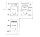
- FIG. 2 is a block diagram for explaining the configuration of the indoor air conditioning system 1 of FIG.
- the indoor air conditioning system 1 including the air conditioner 10 and the humidifier 106 includes a control unit 8.
- the humidifier 106 is instructed to operate by the indoor control unit 81 via the wireless LAN router 210 and the wireless LAN adapter 85.
- the control unit 8 has an indoor control unit 81, an outdoor control unit 86, and a humidifier control unit 89.
- the indoor air conditioning system 1 can instruct the air conditioner 10 and the humidifier 106 by using a communication terminal 230 such as a smartphone.
- a communication terminal 230 such as a smartphone.
- an instruction output from a communication terminal 230 such as a smartphone is transmitted to the air conditioner 10 and the humidifier 106 via the wireless LAN router 210 or via the Internet 240, the broadband router 220, and the wireless LAN router 210. ..
- FIG. 3 is a conceptual diagram showing an example of the air conditioner 10.
- the air conditioner 10 has an indoor unit 2, an outdoor unit 4, and a remote controller 15.
- the indoor unit 2 and the outdoor unit 4 are connected by refrigerant connecting pipes 11 and 12.
- the indoor unit 2, the outdoor unit 4, and the refrigerant connecting pipes 11 and 12 form a refrigerant circuit.
- the indoor unit 2 and the outdoor unit 4 are controlled by the control unit 8.
- the steam compression refrigeration cycle is repeated during the cooling operation, the heating operation, and the dehumidifying operation.
- the indoor unit 2 is installed in the room RM and performs air conditioning in the room RM.
- the indoor unit 2 is attached to the wall WL of the room RM.
- the indoor unit 2 is not limited to the type installed on the wall WL of the room RM.
- the indoor unit 2 may be installed on the ceiling CE or the floor FL, for example.
- FIG. 4 is a cross-sectional view showing an example of the configuration of the indoor unit 2 of the air conditioner 10.
- FIG. 5 is a diagram for explaining a refrigerant circuit of the air conditioner 10.
- the indoor unit 2 has an indoor heat exchanger 21. The indoor unit 2 exchanges heat with the indoor air by passing the indoor air (air in the room RM) through the indoor heat exchanger 21.
- the control unit 8 controls the indoor unit 2 so as to perform a cleaning operation, which is an operation for cleaning the indoor heat exchanger 21.
- a cleaning operation which is an operation for cleaning the indoor heat exchanger 21.
- the control unit 8 controls the humidifier 106 so as to raise the humidity in the room, and cleans the surface of the indoor heat exchanger 21 by generating dew condensation water on the surface of the indoor heat exchanger 21. ..
- the humidifier 6 may be started before the operation of the air conditioner 10 or at the same time as the operation of the air conditioner 10.
- control unit 8 first controls the humidifier 106 so that the humidity in the room reaches a predetermined humidity in the washing operation. In this case, after the room is brought to a predetermined humidity by the humidifier 106, the control unit 8 causes dew condensation water to be generated on the surface of the room heat exchanger 21 to clean the surface.
- the surface of the indoor heat exchanger 21 referred to here includes heat transfer fins 21a.
- the control unit 8 is realized by, for example, a microcomputer. For example, in the cleaning operation, the control unit 8 causes the humidifier 106 to perform a humidifying operation, and then causes the indoor unit 2 to perform a cleaning operation.
- the indoor air conditioning system 1 can raise the humidity in the room to a predetermined humidity by humidifying the washing operation.
- the indoor air conditioning system 1 can perform a cleaning operation in a state where the humidity in the room has risen to a predetermined humidity.
- the indoor air conditioning system 1 can clean the surface of the indoor heat exchanger 21 by causing sufficient dew condensation without being affected by indoor drying due to weather conditions and the like.
- the indoor unit 2 includes an indoor heat exchanger 21, an indoor fan 22, a casing 23, an air filter 24, a drain pan 26, a horizontal flap 27, and a vertical flap. (Not shown) and a discharge unit 29 are provided. Further, the indoor unit 2 includes an indoor temperature sensor 31, an indoor humidity sensor 32, a duct temperature sensor 33, a duct humidity sensor 34, and an indoor heat exchanger temperature sensor 35.
- the casing 23 has a suction port 23a at the upper portion and an outlet 23b at the lower portion.
- the indoor unit 2 drives the indoor fan 22 to suck in the indoor air from the suction port 23a and blow out the air that has passed through the indoor heat exchanger 21 from the air outlet 23b.
- the indoor fan 22 is arranged at a substantially central portion in the casing 23.
- the indoor fan 22 is, for example, a cross-flow fan.
- the indoor heat exchanger 21 is arranged upstream of the indoor fan 22 in the air flow path from the suction port 23a to the air outlet 23b.
- the indoor heat exchanger 21 has a plurality of heat transfer fins 21a and a plurality of heat transfer tubes 21b.
- the indoor air passes between the plurality of heat transfer fins 21a. Further, during heat exchange, air passes between the plurality of heat transfer fins 21a, and at the same time, the refrigerant flows through the heat transfer tube 21b.
- the heat transfer tube 21b is folded a plurality of times and penetrates one heat transfer fin 21a a plurality of times.
- the indoor heat exchanger 21 has a shape that opens downward so as to cover the upper part of the indoor fan 22 when viewed in the extending direction of the heat transfer tube 21b.
- a shape is referred to as a substantially ⁇ shape.
- the indoor heat exchanger 21 has a first heat exchange unit 21F far from the wall WL and a second heat exchange unit 21R close to the wall WL.
- the drain pan 26 is arranged under the front lower part and the rear lower part of the indoor heat exchanger 21 having a substantially ⁇ shape.
- the dew condensation generated in the first heat exchange section 21F of the indoor heat exchanger 21 is received by the drain pan 26 arranged in the lower front part of the indoor heat exchanger 21.
- the dew condensation generated in the second heat exchange unit 21R of the indoor heat exchanger 21 is received by the drain pan 26 arranged in the lower rear part of the indoor heat exchanger 21.
- Horizontal flap 27 A horizontal flap 27 and a vertical flap are arranged at the outlet 23b.
- the horizontal flap 27 changes the wind direction of the air blown from the outlet 23b up and down. Therefore, the horizontal flap 27 is configured so that the angle formed with the horizontal direction can be changed by the motor 27m.
- Air filter 24 An air filter 24 is arranged downstream of the suction port 23a in the casing 23 and upstream of the indoor heat exchanger 21.
- the air filter 24 is installed in the casing 23 so that substantially all the indoor air supplied to the indoor heat exchanger 21 passes through the air filter 24.
- the discharge unit 29 (see FIG. 2) is an active species generating device having a discharge unit inside.
- the discharge unit includes, for example, a needle-shaped electrode and a counter electrode, and a streamer discharge, which is a type of plasma discharge, is generated by applying a high voltage.
- Active species with high oxidative decomposition power are produced when a discharge occurs. These active species include, for example, fast electrons, ions, hydroxide radicals and excited oxygen molecules.
- the active species decomposes harmful components and odorous components in the air composed of small organic molecules such as ammonia, aldehydes and nitrogen oxides.
- the discharge unit 29 is arranged, for example, upstream of the air filter 24 or upstream of the indoor heat exchanger 21.
- (2-1-7) Indoor control unit 81 An indoor control unit 81, which is a component of the control unit 8, is arranged in the indoor unit 2. As shown in FIGS. 2 and 5, the indoor control unit 81 is connected to the motor 22 m of the indoor fan 22, the motor 27 m of the horizontal flap 27, and the reheat dehumidifying valve 28.
- the indoor control unit 81 can control the rotation speed of the motor 22m of the indoor fan 22, the rotation angle of the motor 27m of the horizontal flap 27, and the on / off of the reheat dehumidifying valve 28.
- FIG. 6 is a block diagram for explaining the configuration of the control unit 8.
- the room control unit 81 includes a processor 81a and a memory 81b.
- the processor 81a reads the control program for each operation stored in the memory 81b, and outputs a command required for each device.
- the memory 81b stores the instruction value from the outdoor control unit 86 at any time in addition to the control program for each operation.
- the processor 81a reads the data or the requested value stored in the memory 81b and calculates the necessary control value. Further, the processor 81a has a timer 83 inside.
- a CPU or GPU is adopted as the processor 81a.
- the above description is an example and is not limited to the above description.
- the indoor control unit 81 is connected to the motor 22 m of the indoor fan 22 shown in FIGS. 2 and 5, the motor 27 m of the horizontal flap 27, the reheat dehumidifying valve 28, and the speaker 82.
- the indoor control unit 81 is also connected to the outdoor control unit 86 arranged in the outdoor unit 4.
- the indoor control unit 81 receives a signal from the remote controller 15 and receives an instruction input from the remote controller 15.
- the remote controller 15 has a display screen 15a.
- the indoor control unit 81 can display various information on the display screen 15a of the remote controller 15.
- the indoor control unit 81 can use, for example, the display screen 15a to notify that the cleaning operation cannot be performed.
- the indoor control unit 81 can also notify via the speaker 82 that the cleaning operation cannot be performed.
- FIGS. 2 and 5 show an indoor temperature sensor 31, an indoor humidity sensor 32, and an indoor heat exchanger temperature sensor 35 among the sensors included in the indoor unit 2. These sensors are connected to the indoor control unit 81.
- the indoor control unit 81 detects the temperature of the indoor air by the indoor temperature sensor 31, and detects the relative humidity of the indoor air by the indoor humidity sensor 32.
- the indoor control unit 81 can detect the temperature of the refrigerant flowing in a specific place of the indoor heat exchanger 21 by the indoor heat exchanger temperature sensor 35.
- This specific location is, for example, the location of the heat transfer tube 21b to which the indoor heat exchanger temperature sensor 35 is attached.
- the indoor heat exchanger 21 has a reheat dehumidifying valve 28.
- the first heat exchange unit 21F and the second heat exchange unit 21R are connected via a reheat dehumidifying valve 28.
- the reheat dehumidifying valve 28 is fully opened during cooling operation, heating operation, and weak cooling / dehumidifying operation to allow the refrigerant to flow without depressurization, and close during reheat dehumidification to reduce the pressure of the refrigerant.
- valve mechanisms There are two types of valve mechanisms: a case where a decompression means is provided inside the valve body and a case where a decompression means such as a capillary tube is arranged in parallel with the valve.
- Outdoor unit 4 functions as a heat source unit that supplies heat energy to the indoor unit 2. As shown in FIGS. 2 and 5, the outdoor unit 4 includes a compressor 41, a four-way valve 42, an accumulator 43, an outdoor heat exchanger 44, an outdoor expansion valve 45, an outdoor fan 46, and a casing 47.
- the compressor 41, the four-way valve 42, the accumulator 43, the outdoor heat exchanger 44, the outdoor expansion valve 45, and the outdoor fan 46 are housed in the casing 47.
- the casing 47 has a suction port 47a (see FIG. 5) for sucking in outdoor air and an outlet 47b (see FIGS. 3 and 5) for blowing out the air after heat exchange.
- the suction port 47a is arranged on the rear side of the casing 47.
- the compressor 41 sucks in the gas refrigerant, compresses it, and discharges it.
- the compressor 41 is, for example, a variable displacement compressor whose operating capacity can be changed by adjusting the operating frequency of the motor 41 m with an inverter. The larger the operating frequency, the larger the operating capacity of the compressor 41.
- the four-way valve 42 switches the direction of the flow of the refrigerant in the refrigerant circuit 13.
- the four-way valve 42 has four ports.
- the first port P1 of the four-way valve 42 is connected to the discharge port of the compressor 41.
- the second port P2 of the four-way valve 42 is connected to the first inlet / outlet 44x of the outdoor heat exchanger 44.
- the third port P3 of the four-way valve 42 is connected to the accumulator 43.
- the fourth port P4 of the four-way valve 42 is connected to the second inlet / outlet 21y of the indoor heat exchanger 21.
- Outdoor heat exchanger 44 connects the second inlet / outlet 44y to the first inlet / outlet 45x of the outdoor expansion valve 45.
- the outdoor heat exchanger 44 exchanges heat between the refrigerant flowing into the inside from the first inlet / outlet 44x or the second inlet / outlet 44y and the outdoor air.
- Outdoor expansion valve 45 The outdoor expansion valve 45 connects the second inlet / outlet 45y to the first inlet / outlet 21x of the indoor heat exchanger 21.
- Outdoor control unit 86 In the outdoor unit 4, an outdoor control unit 86 constituting the control unit 8 is arranged. As shown in FIG. 6, the outdoor control unit 86 includes a control device 86a, a storage device 86b, and an arithmetic unit 86c.
- the control device 86a reads the control program stored in the storage device 86b and outputs a command required for each device.
- the storage device 86b stores the requested value from the indoor control unit 81 at any time in addition to each control program.
- the arithmetic unit 86c reads the data or the required value stored in the storage device 86b according to the command of the control device 86a, and calculates the necessary control value.
- a processor such as a CPU or GPU is adopted as the control device 86a and the arithmetic unit 86c.
- the above description is an example and is not limited to the above description.
- the outdoor control unit 86 is connected to the indoor control unit 81. Further, the outdoor control unit 86 is connected to the motor 41 m of the compressor 41, the four-way valve 42, and the motor 46 m of the outdoor fan 46.
- the outdoor control unit 86 can control the operating frequency of the motor 41 m of the compressor 41, the opening degree of the four-way valve 42, and the rotation speed of the motor 46 m of the outdoor fan 46.
- FIGS. 2 and 5 show an outside air temperature sensor 51, a discharge pipe temperature sensor 52, and an outdoor heat exchanger temperature sensor 53 among the sensors included in the outdoor unit 4. These sensors are connected to the outdoor control unit 86.
- the outdoor control unit 86 can detect the temperature of the outdoor air by the outside air temperature sensor 51. Further, the control unit 8 can detect the temperature of the refrigerant flowing through the discharge pipe (the refrigerant pipe connected to the discharge port of the compressor 41) by the discharge pipe temperature sensor 52, and the outdoor heat exchanger 53 by the outdoor heat exchanger 53. The temperature of the refrigerant flowing in 44 specific places can be detected.
- the outdoor control unit 86 monitors the state of the refrigerant in the refrigerant circuit 13 by means of a discharge pipe temperature sensor 52, an outdoor heat exchanger temperature sensor 53, an indoor heat exchanger temperature sensor 35, and the like.
- the refrigerant circuit 13 includes a compressor 41, a four-way valve 42, an accumulator 43, an outdoor heat exchanger 44, an outdoor expansion valve 45, and an indoor heat exchanger 21.
- Refrigerant circulates in the refrigerant circuit 13.
- the refrigerant include fluorocarbons such as R32 refrigerant and R410 refrigerant, carbon dioxide and the like.
- the refrigerant In the steam compression refrigeration cycle, the refrigerant is compressed by the compressor 41 to raise the temperature, and then the refrigerant dissipates heat in the outdoor heat exchanger 44 or the indoor heat exchanger 21. Further, in the steam compression type refrigeration cycle, the refrigerant is decompressed and expanded by the outdoor expansion valve 45, and then the refrigerant is endothermic by the indoor heat exchanger 21 or the outdoor heat exchanger 44.
- FIG. 7 is an exploded perspective view showing a configuration example of the humidifier 106 of FIG.
- the humidifier 106 includes a casing 110, a pre-filter 121, a dust collecting filter 122, a deodorizing filter 123, a blower fan 130, a humidifying filter unit 140, a water tray 150, and a tank 160.
- the casing 110 includes a main body 111 and a front panel 112.
- FIG. 8 is a perspective view showing the appearance of the humidifier 106 of FIG.
- the humidifier 106 has a suction port 113 at the boundary between the front panel 112 and the main body 111.
- the suction port 113 is provided on the lower portion and both sides of the front panel 112.
- the outlet 114 is provided on the upper part of the main body 111.
- An operation panel 115 is provided on the top surface of the main body 111.
- the operation panel 115 is provided with a plurality of operation buttons.
- the pre-filter 121 mainly removes large dust from the passing air.
- the dust collecting filter 122 mainly removes fine dust from the passing air.
- the deodorizing filter 123 contains, for example, activated carbon. The deodorizing filter 123 mainly removes odorous components from the passing air.
- the humidifying filter unit 140 has a humidifying rotor 141 including a humidifying filter 142.
- the humidifying rotor 141 is rotated by a motor 143 (see FIG. 2).
- the humidifying filter 142 receives the supply of water stored in the water tray 150 by rotating together with the humidifying rotor 141.
- the humidifying filter 142 that has been supplied with water supplies water to the passing air.
- the humidifying filter unit 140 stops humidification.
- the water tray 150 replenishes the water supplied to the humidifying filter 142 by receiving the water supply from the tank 160.
- the user replenishes the tank 160 with water.
- the humidifier control unit 89 includes a processor 89a and a memory 89b.
- the processor 89a reads the control program stored in the memory 89b and outputs a command required for each device.
- the memory 89b stores the requested value from the indoor control unit 81 at any time in addition to each control program.
- the processor 89a reads the data or the requested value stored in the memory 89b and calculates the necessary control value.
- processor 89a a processor such as a CPU or GPU is adopted.
- the above description is an example and is not limited to the above description.
- the control unit 8 can control the motor 143 via the humidifier control unit 89. Therefore, the control unit 8 can make the humidifier 106 perform the humidifying operation by turning on the motor 143, and stop the humidifying operation on the humidifier 106 by turning off the motor 143.
- the humidifier 106 includes an indoor temperature sensor 171, an indoor humidity sensor 172, and a water supply sensor 173.
- the indoor temperature sensor 171 and the indoor humidity sensor 172 and the water supply sensor 173 are connected to the humidifier control unit 89.
- control unit 8 can detect the temperature of the room air and the relative humidity by the room temperature sensor 171 and the room humidity sensor 172 via the humidifier control unit 89.
- the control unit 8 of the first embodiment may use the indoor temperature sensor 31 and the indoor humidity sensor 32 or the indoor temperature sensor 171 and the indoor humidity sensor 172 for control.
- the control unit 8 may use both sensors at the same time for control, for example, using the average value of the indoor temperature sensors 31 and 171 as the temperature of the indoor air. Further, the control unit 8 may use both sensors at the same time for control, for example, using the average value of the indoor humidity sensors 32 and 172 as the relative humidity of the indoor air.
- the normal operation of the indoor air conditioning system 1 includes, for example, cooling operation, heating operation, dehumidifying operation, ventilation operation, and air cleaning operation.
- the normal operation is an operation other than the washing operation.
- the normal operation is not limited to the above-mentioned cooling operation and heating operation.
- control unit 8 Before the start of the cooling operation, the control unit 8 is instructed by, for example, the remote controller 15 to perform the cooling operation and the target temperature. During the cooling operation, the control unit 8 switches the four-way valve 42 to the state shown by the solid line in FIG.
- the four-way valve 42 causes the refrigerant to flow between the first port P1 and the second port P2, and the refrigerant to flow between the third port P3 and the fourth port P4.
- the four-way valve 42 during the cooling operation causes the high-temperature and high-pressure gas refrigerant discharged from the compressor 41 to flow through the outdoor heat exchanger 44.
- the outdoor heat exchanger 44 heat is exchanged between the refrigerant and the outdoor air supplied by the outdoor fan 46.
- the refrigerant radiated by the outdoor heat exchanger 44 is decompressed by the outdoor expansion valve 45 and flows into the indoor heat exchanger 21.
- the indoor heat exchanger 21 heat exchange is performed between the refrigerant and the indoor air supplied by the indoor fan 22.
- the refrigerant absorbed by the heat exchange in the indoor heat exchanger 21 is sucked into the compressor 41 via the four-way valve 42 and the accumulator 43.
- the indoor air cooled by the indoor heat exchanger 21 is blown out from the indoor unit 2 to the room RM to cool the room.
- the indoor heat exchanger 21 functions as a refrigerant evaporator to warm the indoor air in the room RM, and the outdoor heat exchanger 44 functions as a refrigerant radiator.
- control unit 8 Before the start of the heating operation, the control unit 8 is instructed by, for example, the remote controller 15 to perform the heating operation and the target temperature. During the heating operation, the control unit 8 switches the four-way valve 42 to the state shown by the broken line in FIG.
- the four-way valve 42 causes the refrigerant to flow between the first port P1 and the fourth port P4, and the refrigerant to flow between the second port P2 and the third port P3.
- the four-way valve 42 during the heating operation causes the high-temperature and high-pressure gas refrigerant discharged from the compressor 41 to flow through the indoor heat exchanger 21.
- the indoor heat exchanger 21 heat exchange is performed between the refrigerant and the indoor air supplied by the indoor fan 22.
- the refrigerant radiated by the indoor heat exchanger 21 is decompressed by the outdoor expansion valve 45 and flows into the outdoor heat exchanger 44.
- the outdoor heat exchanger 44 heat is exchanged between the refrigerant and the indoor air supplied by the outdoor fan 46.
- the refrigerant absorbed by the heat exchange in the outdoor heat exchanger 44 is sucked into the compressor 41 via the four-way valve 42 and the accumulator 43.
- the indoor air heated by the indoor heat exchanger 21 is blown out from the indoor unit 2 to the room RM to heat the room.
- the indoor heat exchanger 21 functions as a refrigerant radiator to warm the indoor air in the room RM
- the outdoor heat exchanger 44 functions as a refrigerant evaporator.
- the first dehumidification operation is performed so that substantially the entire indoor heat exchanger 21 is in the evaporation area.
- a second dehumidification operation is performed in which at least a part of the windward side of the indoor heat exchanger 21 is set as an evaporation area, while the remaining part of the indoor heat exchanger 21 is set as a superheat area.
- the portion upstream of the reheat dehumidification valve 28 is the condensation region, while the portion downstream of the reheat dehumidification valve 28 is the evaporation region. Is done.
- control unit 8 switches the four-way valve 42 to the state shown by the solid line in FIG.
- the four-way valve 42 causes the refrigerant to flow between the first port P1 and the second port P2, and the refrigerant to flow between the third port P3 and the fourth port P4. Therefore, in the refrigerant circuit 13, the direction in which the refrigerant flows is the same during the dehumidifying operation and the cooling operation.
- the refrigeration cycle is also carried out in the refrigerant circuit 13 of the dehumidifying operation.
- the first dehumidifying operation has a high sensible heat capacity, which is the ability to change the room temperature.
- an evaporation region is not only when the entire indoor heat exchanger 21 is made into an evaporation region, but also only a part of the indoor heat exchanger 21 except for a part. Including when making the evaporation area.
- At least a part of the windward side of the first heat exchange section 21F is set as an evaporation region, while the remaining portion of the first heat exchange section 21F and the second heat exchange section 21R are set as a superheat zone.
- the control unit 8 controls the compressor 41 and the outdoor expansion valve 45 so that the evaporation area becomes a predetermined volume (for example, 2/3 of the total volume of the indoor heat exchanger 21) or less during the second dehumidification operation.
- the opening degree of the outdoor expansion valve 45 is usually smaller than the opening degree of the outdoor expansion valve 45 during the first dehumidifying operation.
- the sensible heat capacity of the second dehumidifying operation is lower than that of the first dehumidifying operation, it is possible to dehumidify the room while suppressing a decrease in room temperature when the heat load in the room is neither high nor low.
- the pressure is reduced by closing the reheat dehumidification valve 28.
- the first heat exchange unit 21F is set to the condensation region, while the second heat exchange unit 21R is set to the evaporation region.
- the first heat exchange unit 21F functions as a condensed region, it is possible to dehumidify the room while suppressing a decrease in room temperature as compared with the second dehumidification operation.
- control unit 8 Before the start of the blower operation, the control unit 8 is instructed to perform the blower operation, for example, from the remote controller 15. During the blowing operation, the control unit 8 stops the compressor 41 and stops the refrigerating cycle in the refrigerant circuit 13.
- the remote controller 15 may instruct the target air volume, or the indoor unit 2 may automatically select the target air volume.
- the control unit 8 controls the motor 22m of the indoor fan 22 so that the target air volume is reached.
- control unit 8 is configured to be able to increase the rotation speed in the order of the L tap, the M tap, and the H tap from the LL tap having the lowest rotation speed.
- the indoor air conditioning system 1 of the first embodiment performs an air cleaning operation using the discharge unit 29.
- the air cleaning operation is an operation of suppressing harmful components and / or odor components in the air.
- the air cleaning operation is, for example, an operation in which harmful components and / or odor components are suppressed by the decomposing power of streamer discharge.
- the first humidification operation is an operation of humidifying at the same time as heating.
- the control unit 8 controls the air conditioner 10 and the humidifier 106 so that the heating operation for the room RM by the air conditioner 10 and the humidification operation for the room RM by the humidifier 106 are simultaneously performed. ..
- the second humidification operation is an operation in which the heating operation in the first humidification operation is stopped and only the humidification operation is performed.
- the control unit 8 controls the air conditioner 10 and the humidifier 106 so that the room RM is humidified by the humidification operation of the humidifier 106.
- the heating operation is not performed, but the air conditioner 10 is used to blow air.
- the indoor air conditioning system 1 performs a cleaning operation using the humidifier 106.
- the humidifier 106 sucks in the indoor air from the suction port 113, moisturizes the indoor air, and blows it out into the room RM from the outlet 114.
- the indoor air conditioning system 1 performs the first humidification operation by using the air conditioner 10 and the humidifier 106.
- the control unit 8 causes the air conditioner 10 to perform the heating operation of the room RM, and at the same time causes the humidifier 106 to humidify the room RM.
- the control unit 8 stops the operation of the air conditioner 10 and causes the humidifier 106 to humidify.
- FIG. 9 is a flowchart for explaining the operation of the indoor air conditioning system 1.
- the control unit 8 is instructed to start the washing operation (in the case of manual start), and the control unit 8 automatically determines the start of the washing operation (automatically). In case of start).
- the indoor air conditioning system 1 of the first embodiment corresponds to both the case of manual start and the case of automatic start.
- the indoor air conditioning system 1 can also be configured to support either the manual start case or the automatic start case.
- Step S1 the control unit 8 determines whether or not there is an instruction for cleaning operation. When the control unit 8 determines that there is an instruction for the cleaning operation, the control unit 8 proceeds to step S2.
- the washing operation start button for instructing the washing operation of the remote controller 15 may be pressed.
- control unit 8 determines that there is no instruction for cleaning operation, the control unit 8 proceeds to step S11.
- Step S2 the control unit 8 controls the motor 27m so as to open the horizontal flap 27 and fix it at a predetermined angle in order to start the washing operation.
- the angle of the horizontal flap 27 is preferably an angle at which the air blown from the indoor unit 2 does not directly hit the person even if there is a person in the room RM.
- control unit 8 controls the discharge unit 29 so as to start the streamer discharge. If the horizontal flap 27 has already been opened before the process of step S2, it is maintained. Further, before the process of step S2, when the streamer discharge has already started, the state in which the streamer discharge is being performed is maintained. The streamer discharge ends when the cleaning operation ends.
- the indoor air conditioning system 1 can clean the indoor heat exchanger 21.
- the indoor air conditioning system 1 can also be configured so as to stop the discharge of the discharge unit 29 and perform the cleaning operation.
- step S3 the control unit 8 determines whether or not the humidity of the air in the room RM has reached the predetermined value AH1.
- the control unit 8 determines that the indoor humidity value has reached the predetermined value AH1 (predetermined humidity) not only when the indoor humidity value is the predetermined value AH1 but also when the indoor humidity value exceeds the predetermined value AH1. do.
- AH1 predetermined humidity
- the humidity absolute humidity may be used, but relative humidity may be substituted. When substituting with relative humidity, the detected value of relative humidity may be adjusted according to the atmospheric temperature, if necessary.
- the control unit 8 detects the indoor temperature by the indoor temperature sensor 31 and detects the relative humidity in the room by the indoor humidity sensor 32.
- the control unit 8 uses the air temperature value MT detected by the indoor temperature sensor 31 and the air relative humidity value MRH detected by the indoor humidity sensor 32 in the room RM.
- the absolute humidity of the air inside can be calculated.
- control unit 8 determines that the humidity in the room has reached the predetermined value AH1, the control unit 8 proceeds to step S4.
- control unit 8 determines that the humidity in the room has not reached the predetermined value AH1, the control unit 8 proceeds to step S31.
- Step S4 the control unit 8 starts the cleaning operation in step S4.
- the air conditioner 10 operates the indoor heat exchanger 21 as an evaporator, as in the cooling operation or the dehumidifying operation.
- the control unit 8 controls the air conditioner 10 so as to perform the same operation as the first dehumidifying operation.
- the control unit 8 has started counting by the timer 83 from the start of the washing operation.
- Step S5 the control unit 8 determines whether or not the predetermined time tt2 has elapsed since the washing operation was started.
- the control unit 8 determines that "a predetermined time tt2 has elapsed since the start of the washing operation"
- the control unit 8 ends the first dehumidifying operation and proceeds to step S6.
- control unit 8 determines that "the predetermined time tt2 has not elapsed since the start of the cleaning operation"
- the control unit 8 returns to step S4 and continues the cleaning operation.
- Step S6 The control unit 8 ends the cleaning operation in step S6.
- Step S11 Steps S1 to S6 are the main flow of operation. On the other hand, if the control unit 8 determines in step S1 that there is no instruction for the cleaning operation, the control unit 8 determines in step S11 whether or not the condition for starting the cleaning operation is satisfied.
- control unit 8 determines that "the conditions for starting the cleaning operation are satisfied"
- the control unit 8 proceeds to step S2.
- the conditions for shifting to the washing operation in step S11 will be described later in "(3-3) Conditions for shifting to the washing operation".
- control unit 8 determines that "the condition for starting the cleaning operation is not satisfied"
- the control unit 8 returns to step S1.
- Step S31 Further, if the control unit 8 determines in step S3 that the humidity in the room has not reached the predetermined value AH1, the control unit 8 determines in step S31 whether it is the first humidification operation or the first humidification operation based on the temperature in the room. 2 In order to select the humidification operation, it is determined whether or not the temperature detected by the room temperature sensor 31 is equal to or higher than the predetermined temperature T1.
- Step S32A If the control unit 8 determines in the previous step S31 that "the temperature detected by the indoor temperature sensor 31 is not equal to or higher than the predetermined temperature T1", the control unit 8 performs the above-mentioned first humidification operation in the step S32A.
- Step S32B If the control unit 8 determines in the previous step S31 that "the temperature detected by the indoor temperature sensor 31 is equal to or higher than the predetermined temperature T1", the control unit 8 performs the above-mentioned second humidification operation in the step S32B.
- the humidification operation by the humidifier 106 is performed.
- the humidification capacity is set to be equal to or higher than the maximum value of the humidification capacity that appears in the humidification operation in the normal operation.
- the washing operation the comfort of the room RM is not emphasized, but rather, the priority is given to finishing the washing operation quickly.
- the first humidification operation or the second humidification operation is performed with the maximum value or more of the humidification capacity appearing in the humidification operation of the normal operation so that the humidity in the room reaches the predetermined value AH1 quickly.
- the H tap is selected in the first humidification operation and the second humidification operation. ..
- the control unit 8 controls the air conditioner 10 together with the humidifier 106 so that the heating operation is performed at the same time as the humidification operation.
- the control unit 8 controls the air conditioner 10 so as to reach a target temperature preset for the cleaning operation.
- the heating operation performed by the air conditioner 10 in the washing operation is the same as the operation of the air conditioner 10 in the heating operation in the normal operation, so the description thereof is omitted here.
- Step S33 the control unit 8 determines in step S33 whether or not a predetermined time tt1 has elapsed from the start of humidification in either the first humidification operation or the second humidification operation. ..
- control unit 8 determines that the predetermined time tt1 has not elapsed, the control unit 8 returns to step S3 and continues the first humidification operation or the second humidification operation until the humidity in the room reaches the predetermined value AH1.
- control unit 8 determines that the predetermined time tt1 has elapsed, the control unit 8 proceeds to step S34.
- Step S34 If the control unit 8 determines in step S33 that "the predetermined time tt1 has elapsed", the control unit 8 notifies the abnormality in step S34 and returns to step S6.
- control unit 8 automatically determines whether or not to shift to the cleaning operation in step S11 of FIG.
- FIG. 10 is a flowchart showing an operation example of the control unit when automatically shifting to the cleaning operation. The process of the control unit 8 for determining the transition condition of the washing operation will be described with reference to FIG.
- step S41 the control unit 8 determines whether or not the operation mode is an operation other than the cleaning operation.
- the control unit 8 determines that "the operation mode is not an operation other than the cleaning operation (the operation mode is the cleaning operation)"
- the process proceeds to step S48 and the integrated drive time is reset.
- control unit 8 determines that the operation mode is an operation other than the cleaning operation, the control unit 8 proceeds to step S42.
- step S42 the control unit 8 determines whether or not the operation mode is an operation other than the cooling operation and the dehumidifying operation.
- the control unit 8 determines that "the indoor air conditioning system 1 is performing an operation other than the cooling operation and the dehumidifying operation", in other words, the indoor air conditioning system 1 performs a heating operation, a blowing operation, or an air cleaning operation. If so, the process proceeds to step S43.
- control unit 8 determines that "the indoor air conditioning system 1 is performing an operation other than the cooling operation and the dehumidifying operation" If the control unit 8 does not determine that "the indoor air conditioning system 1 is performing an operation other than the cooling operation and the dehumidifying operation", the process proceeds to step S421.
- Step S43 The control unit 8 counts the drive time of the indoor fan 22 in step S43.
- the processor 81a counts the drive time of the indoor fan 22, for example, by using the timer 83.
- the processor 81a stores the counted drive time in the memory 81b.
- the drive time of the indoor fan 22 is counted until the current operation is completed.
- the drive time of the indoor fan 22 is not counted.
- the drive time of the indoor fan 22 is counted in the first drive time and the second drive time.
- the first drive time is the drive time of the indoor fan 22 during the heating operation of the indoor unit 2.
- the second drive time is the drive time of the indoor fan 22 during the ventilation operation and the air purification operation.
- Step S421 On the other hand, if the control unit 8 does not determine that the indoor air conditioning system 1 is "operating other than the cooling operation or the dehumidifying operation" in the previous step S42, in other words, the indoor air conditioning system 1 is in the cooling operation or the dehumidifying operation. In this step S421, it is determined whether or not the operation time of the cooling operation or the dehumidifying operation is tt3 or more for the predetermined time.
- the operating time of the cooling operation or the dehumidifying operation is counted by the processor 81a using, for example, the timer 83.
- the processor 81a stores the counted operation time in the memory 81b.
- control unit 8 determines that "the operation time of the cooling operation or the dehumidification operation is tt3 or more for the predetermined time"
- the control unit 8 proceeds to step S48 and resets the integrated drive time of the indoor fan 22.
- the control unit 8 resets the integrated drive time when the indoor unit 2 that causes dew condensation is cooled or dehumidified by the indoor heat exchanger 21.
- control unit 8 determines that the operation time of the cooling operation and the dehumidification operation is less than the predetermined time tt3, the control unit 8 proceeds to step S44 without counting the drive time of the indoor fan 22.
- step S44 the control unit 8 determines whether or not the current operation has been completed. In other words, the control unit 8 controls so that the drive time of the indoor fan 22 when the indoor unit 2 is operating to cause dew condensation on the indoor heat exchanger 21 in normal operation is not included in the integrated drive time.
- control unit 8 determines that the current operation has ended, the control unit 8 proceeds to step S45.
- Step S45 The control unit 8 calculates the integrated drive time of the indoor fan 22 in step S45.
- the control unit 8 integrates the drive times stored in the memory 81b to calculate the integrated drive time.
- the integrated drive time is calculated by totaling the drive times of the indoor fans 22 for the heating operation, the ventilation operation, and the air cleaning operation.
- the method of calculating the integrated drive time is not limited to the method of simply summing the drive times of each operation.
- the control unit 8 can be configured to calculate the integrated drive time by weighting each type of operation.
- step S46 the control unit 8 determines whether or not the integrated drive time is equal to or longer than the predetermined drive time CT1. When the control unit 8 determines that the integrated drive time is equal to or longer than the predetermined drive time CT1, the control unit 8 proceeds to step S47.
- step S47 in FIG. 10 is an example of the determination in step S11 in FIG.
- the integrated drive time is equal to or longer than the predetermined drive time CT1, it is determined that the condition for shifting to the cleaning operation is satisfied.
- condition for shifting to the cleaning operation does not necessarily have to be that the integrated drive time is equal to or longer than the predetermined drive time CT1.
- a condition for shifting to the washing operation for example, a condition that the normal operation is stopped may be added.
- the control unit 8 returns to step S41 and repeats the step for integrating the integrated drive time when it is determined that the integrated drive time is less than the predetermined drive time CT1.
- Step S47 the control unit 8 sets a flag indicating that the transition condition to the washing operation is satisfied and stores it in the memory 81b.
- Step S48 The control unit 8 resets the integrated drive time in step S48.
- Step S49 If the indoor air conditioning system 1 is not stopped in step S49, the control unit 8 returns to step S41 and repeats the step for integrating the integrated drive time.
- step S41, step S48 and step S49 are repeated, so that the integrated drive time is not counted even if the indoor fan 22 is driven.
- Humidifier control in the washing operation Humidification operation by the humidifier 106 is performed in both the first humidification operation and the second humidification operation.
- the humidification operation performed in the first humidification operation and the second humidification operation is set so as to be equal to or more than the maximum value of the humidification capacity appearing in the humidification operation of the normal operation.
- FIG. 11A is an operation flowchart of the humidifier control in the washing operation.
- the flow after step S321 shows the control operation of the control unit 8 performed inside the steps S32A and S32B of FIG.
- step S321 the control unit 8 determines whether or not there is a humidification operation start command for the humidifier 106.
- the control unit 8 proceeds to step S322 when there is a command to start the humidifying operation of the humidifier 106.
- Step S322 the control unit 8 gives a notification prompting confirmation of the amount of residual water in the tank 160.
- the purpose of the notification is to prevent the tank 160 of the humidifier 106 from running out of water during the washing operation by prompting the confirmation of the amount of residual water in the tank 160 of the humidifier 106 when the indoor heat exchanger 21 is washed. This is to secure the condensed water (condensed water) required for cleaning.
- the control unit 8 displays a message prompting water supply to the tank 160 via the display screen 15a of the remote controller 15, or emits a voice message prompting water supply to the tank 160 via the speaker 82. , Etc. are adopted.
- Step S323 The control unit 8 determines in step S323 whether or not the cleaning operation start button is turned on. As a response from the user to the notification in step S322, the control unit 8 waits for the washing operation until the washing operation start button is turned on.
- the "washing operation start button" is provided on the remote controller 15, but instead, an instruction to start the washing operation can be given from a communication terminal 230 such as a smartphone.
- control unit 8 determines that the cleaning operation start button has been turned on.
- the control unit 8 proceeds to step S324.
- the control unit 8 waits for the cleaning operation.
- Step S324 The control unit 8 starts the operation of the humidifier 106 in step S324.
- the humidifying capacity of the humidifier 106 is set to L tap, M tap, and H tap in ascending order, and the H tap is selected in the first humidifying operation and the second humidifying operation during the washing operation.
- Step S325) the control unit 8 determines whether or not there is a stop command for the washing operation. This is because the user may want to stop the washing operation, and in such a case, it is necessary to forcibly end the washing operation even during the humidifying operation.
- control unit 8 When the control unit 8 is instructed to stop the cleaning operation, the control unit 8 proceeds to step S6 in FIG.
- the control unit 8 may notify the stop of the washing operation via a communication terminal 230 such as a smartphone or a remote controller 15.
- control unit 8 proceeds to step S33 in FIG. 9 when there is no stop command for the cleaning operation.
- step S32A of FIG. 9 As described above, in the first humidification operation of step S32A of FIG. 9 and the second humidification operation of step S32B, the controls of steps S321 to S325 are executed.
- step S322 of the flowchart of FIG. 11A a notification prompting confirmation of the residual water amount of the tank 160 is performed. It is not limited to.
- FIG. 11B is an operation flowchart of the humidifier control in the cleaning operation of the indoor air conditioning system according to the first modification.
- step S322 in FIG. 11A is replaced with step S322x.
- step S322x Since the other steps are the same as in FIG. 11A, only step S322x will be described here, and the description of the other steps will be omitted.
- Step S322x the control unit 8 gives a notification prompting water supply to the tank 160.
- the notification means is performed via the display screen 15a of the remote controller 15 or the speaker 82.
- the tank 160 may run out of water during the cleaning operation, and a satisfactory cleaning operation may not be performed. There is.
- step S323 of the flowchart of FIG. 11A it is determined whether or not the washing operation start button is turned on, but the present invention is not limited to this.
- FIG. 11C is an operation flowchart of the humidifier control in the cleaning operation of the indoor air conditioning system according to the second modification.
- step S322 in FIG. 11A is replaced by step S322y
- step S323 in FIG. 11A is replaced by step 323x.
- Step S322y the control unit 8 gives a notification prompting water supply to the tank 160, and at the same time, starts timing.
- the notification means is performed via the display screen 15a of the remote controller 15 or the speaker 82.
- Timekeeping is performed by a timer 83 built in the processor 81a of the indoor control unit 81.
- Step S323x the control unit 8 determines whether or not a predetermined time has elapsed after the notification in step 322y.
- the timer 83 activated in the previous step S322y performs the measurement of the predetermined time.
- the predetermined time can be set arbitrarily, but the initial setting is 5 minutes.
- the 5 minutes are assumed to be the time required for the user to supply water to the tank 160 after the notification prompting the water supply to the tank 160 is given.
- the control unit 8 proceeds to step 324 and starts the humidification operation when 5 minutes have elapsed after notifying the tank 160 to supply water.
- the tank 160 is urged to supply water, and then the user waits for the water to be supplied to the tank 160 to prevent the tank 160 from running out during the washing operation. ..
- FIG. 12 is an operation flowchart of the humidifier control in the cleaning operation of the indoor air conditioning system according to the third modification.
- the flow after step S51 shows the control operation of the control unit 8 performed inside the steps S352A and S32B of FIG.
- step S51 the control unit 8 determines whether or not there is a humidification operation start command for the humidifier 106.
- the control unit 8 proceeds to step S52 when there is a humidification operation start command for the humidifier 106.
- Step S52 The control unit 8 detects or estimates the amount of residual water in the tank 160 in step S52.
- the control unit 8 detects the residual water amount in the tank 160 by the water amount sensor.
- the control unit 8 estimates the amount of residual water in the tank 160 based on the operation history of the humidifier 106 and the water supply history to the tank 160.
- the processor 89a counts the water supply time to the tank 160 and the humidification operation time performed after the latest water supply, and stores them in the memory 89b.
- the processor 89a reads the humidification operation time from the memory 89b, calculates the amount of water consumed in the tank 160 from the humidification operation time, and further calculates the amount of residual water in the tank 160.
- the control unit 8 detects or estimates the amount of residual water in the tank 160, and then proceeds to step S53.
- step S53 the control unit 8 determines whether or not the amount of residual water in the tank 160 is less than the first predetermined amount.
- the process proceeds to step S54, and when it is determined that the residual water amount in the tank 160 is equal to or more than the first predetermined amount, the step S54 is performed. Proceed to S57.
- Step S54 the control unit 8 gives a notification to encourage water supply to the tank 160.
- the control unit 8 displays a message prompting water supply to the tank 160 via the display screen 15a of the remote controller 15, or emits a voice message prompting water supply to the tank 160 via the speaker 82. , Etc. are adopted.
- Step S55 the control unit 8 again detects or estimates the amount of residual water in the tank 160.
- the control unit 8 detects the residual water amount in the tank 160 by the water amount sensor.
- the control unit 8 estimates the amount of residual water in the tank 160 by the following method.
- the humidifier 106 has a switch mechanism in which the contacts are turned on by the gravity of the supplied tank 160.
- the on / off signal of the switch mechanism is input to the humidifier control unit 89 of the humidifier 106, the on / off operation of the switch mechanism can be detected by the humidifier control unit 89. Therefore, when the switch mechanism is switched on and off after the notification prompting the water supply to the tank 160, it can be estimated that the water supply to the tank 160 has been performed to the full water level (second predetermined amount or more).
- the control unit 8 detects or estimates the amount of residual water in the tank 160, and then proceeds to step S53.
- step S56 the control unit 8 determines whether or not the amount of residual water in the tank 160 is equal to or greater than the second predetermined amount.
- the second predetermined amount is set to a value larger than the first predetermined amount. This is because if the second predetermined amount and the first predetermined amount have the same value, the determination of less than that value and more than that value becomes unstable.
- step S57 When the control unit 8 determines that the amount of residual water in the tank 160 is equal to or greater than the second predetermined amount, the process proceeds to step S57, and when it is determined that the amount of residual water in the tank 160 is less than the second predetermined amount, the step S57 is performed. Return to S54.
- Step S57 The control unit 8 starts the humidification operation by the humidifier 106 in step S57.
- the humidifying capacity of the humidifier 106 is set to L tap, M tap, and H tap in ascending order, and the H tap is selected in the first humidifying operation and the second humidifying operation during the washing operation.
- Step S58 the control unit 8 determines whether or not there is a stop command for the washing operation. This is because the user may want to stop the washing operation, and in such a case, it is necessary to forcibly end the washing operation even during the humidifying operation.
- control unit 8 When the control unit 8 is instructed to stop the cleaning operation, the control unit 8 proceeds to step S6 in FIG.
- the control unit 8 may notify the stop of the washing operation via a communication terminal 230 such as a smartphone or a remote controller 15.
- control unit 8 proceeds to step S33 in FIG. 9 when there is no stop command for the cleaning operation.
- step S51 to S58 is executed in the first humidification operation of step S32A of FIG. 9 and the second humidification operation of step S32B.
- the control unit 8 has a second predetermined amount or more in which the residual water amount of the tank 160 is larger than the first predetermined amount.
- the washing operation may be started by omitting the notification for confirming the residual water amount of the tank 160 and the notification for prompting the water supply to the tank 160.
- the control unit 8 has an indoor control unit 81 that determines the execution of the cleaning operation.
- the control unit 8 notifies the user via the display screen 15a of the remote controller 15 or the speaker 82 that the cleaning operation is performed, and the rest of the tank 160.
- At least one of the notification prompting the confirmation of the amount of water and the notification prompting the water supply to the tank 160 is performed.
- the humidifier 106 detects or estimates the residual water amount of the tank 160 and determines that the residual water amount is equal to or less than the first predetermined amount, the humidifier 106 passes through the display screen 15a of the remote controller 15 or the speaker 82. The user is notified to urge the user to supply water to the tank 160.
- the control unit 8 estimates the residual water amount of the tank 160 based on the operation history of the humidifier 106 acquired by the humidifier control unit 89 and the water supply history to the tank 160, so that the residual water amount detecting means can be used. It is possible to adopt a humidifier that does not exist.
- control unit 8 starts the cleaning operation when a signal for starting the cleaning operation is input from the remote controller 15 in response to the notification.
- the humidifier 106 is instructed to operate by the indoor control unit 81 of the air conditioner 10 via the wireless LAN router 210 and the wireless LAN adapter 85. Met.
- FIG. 13 is a flowchart for explaining the operation of the indoor air conditioning system 1 according to the second embodiment. Hereinafter, the cleaning operation will be described with reference to the flowchart of FIG.
- steps S31 to S34 in FIG. 9 are replaced with steps S131 to S134.
- steps S1 to S6 will be omitted, and steps S131 to S134 will be described.
- Step S131 If the control unit 8 determines in step S3 that the humidity in the room has not reached the predetermined value AH1, the control unit 8 activates the counter in step S131 to set the number of notifications N for prompting humidification. Count.
- step S1 0 if the process proceeds from step S1 to step S131 in a state where the notification for prompting humidification has not been performed yet.
- step S132 the control unit 8 determines whether or not the number of times N of the notifications for prompting humidification has reached the predetermined number of times X.
- the control unit 8 proceeds to step S133.
- control unit 8 determines that the number of times N of notifications has reached the predetermined number of times X, the control unit 8 proceeds to step S6 to stop the washing operation.
- Step S133 the control unit 8 gives a notification to encourage humidification via the display screen 15a of the remote controller 15 or the speaker 82.
- the notification prompting humidification includes a notification prompting "start the humidifier 206 to perform humidification operation" and a notification prompting "operate to increase the humidifying capacity of the humidifier 206".
- the control unit 8 cannot grasp whether or not the humidifier 206 is operating.
- the message B "Please increase the humidifying capacity of the humidifier because the cleaning operation is performed" may be notified.
- the message C "Please restore the humidifying capacity of the humidifier because the cleaning operation is performed.” Is notified. You may.
- the message D "Since the cleaning operation is performed, please humidify for ⁇ hours.” May be notified.
- the ⁇ time is the time required for the washing operation.
- step S134 the control unit 8 determines whether or not a predetermined time ts1 has elapsed since the notification for prompting humidification was performed.
- the control unit 8 determines that the predetermined time ts1 has elapsed, the control unit 8 returns to step S3.
- the notification waits for the elapse of the predetermined time ts1 with the expectation that the user is performing the humidification operation by the humidifier 206. Then, it is determined by returning to step S3 whether or not the humidification operation is actually performed.
- control unit 8 repeats the routine of notifying the humidification prompt and waiting for the lapse of the predetermined time ts1 N times, and if the humidity in the room still does not reach the predetermined value AH1, the control unit 8 does not reach the predetermined value AH1.
- Reference numeral 8 presumes that the humidifier 206 is in a stopped state, and stops the washing operation.
- the control unit 8 may notify the stop of the washing operation via a communication terminal 230 such as a smartphone or a remote controller 15.
- the control unit 8 has an indoor control unit 81 that determines the execution of the cleaning operation.
- the control unit 8 notifies the user via the display screen 15a of the remote controller 15 or the speaker 82 that the cleaning operation is performed, and the rest of the tank 160.
- At least one of the notification prompting the confirmation of the amount of water and the notification prompting the water supply to the tank 160 is performed.
- control unit 8 starts the cleaning operation when a signal for starting the cleaning operation is input from the remote controller 15 in response to the notification.
- the indoor heat exchanger 21 functions as an evaporator and the moisture contained in the indoor air is condensed in the indoor heat exchanger 21 to condense the indoor heat exchanger 21.
- the explanation is based on the assumption that the dirt adhering to the surface is washed away.
- the cleaning operation is not limited to this, and the cleaning operation includes an operation of performing a freezing operation in which the surface temperature of the indoor heat exchanger 21 is set below the freezing point, and thawing after the freezing operation is completed to clean the indoor heat exchanger. Is done.
Landscapes
- Engineering & Computer Science (AREA)
- Chemical & Material Sciences (AREA)
- Combustion & Propulsion (AREA)
- Mechanical Engineering (AREA)
- General Engineering & Computer Science (AREA)
- Signal Processing (AREA)
- Physics & Mathematics (AREA)
- Fuzzy Systems (AREA)
- Mathematical Physics (AREA)
- Human Computer Interaction (AREA)
- Air Conditioning Control Device (AREA)
- Devices For Blowing Cold Air, Devices For Blowing Warm Air, And Means For Preventing Water Condensation In Air Conditioning Units (AREA)
- Air Humidification (AREA)
Priority Applications (1)
| Application Number | Priority Date | Filing Date | Title |
|---|---|---|---|
| CN202180052988.4A CN115968434B (zh) | 2020-08-28 | 2021-06-29 | 室内空调系统 |
Applications Claiming Priority (2)
| Application Number | Priority Date | Filing Date | Title |
|---|---|---|---|
| JP2020144802A JP7116335B2 (ja) | 2020-08-28 | 2020-08-28 | 室内空調システム |
| JP2020-144802 | 2020-08-28 |
Publications (1)
| Publication Number | Publication Date |
|---|---|
| WO2022044530A1 true WO2022044530A1 (ja) | 2022-03-03 |
Family
ID=80354962
Family Applications (1)
| Application Number | Title | Priority Date | Filing Date |
|---|---|---|---|
| PCT/JP2021/024525 WO2022044530A1 (ja) | 2020-08-28 | 2021-06-29 | 室内空調システム |
Country Status (3)
| Country | Link |
|---|---|
| JP (1) | JP7116335B2 (zh) |
| CN (1) | CN115968434B (zh) |
| WO (1) | WO2022044530A1 (zh) |
Citations (2)
| Publication number | Priority date | Publication date | Assignee | Title |
|---|---|---|---|---|
| JP6498374B1 (ja) * | 2018-10-05 | 2019-04-10 | 日立ジョンソンコントロールズ空調株式会社 | 空気調和機、空気調和機の制御方法およびプログラム |
| CN109916001A (zh) * | 2019-03-21 | 2019-06-21 | 青岛海尔空调器有限总公司 | 空调器自清洁加湿控制方法 |
Family Cites Families (10)
| Publication number | Priority date | Publication date | Assignee | Title |
|---|---|---|---|---|
| JP3469802B2 (ja) * | 1999-02-12 | 2003-11-25 | 三洋電機株式会社 | 洗浄機 |
| JP6513441B2 (ja) * | 2015-03-19 | 2019-05-15 | 三菱電機株式会社 | 空気調和システムおよび空気調和制御方法 |
| CN106247556B (zh) * | 2016-08-22 | 2019-10-01 | 青岛海尔空调器有限总公司 | 空调自清洁控制方法 |
| CN106969467A (zh) * | 2017-04-01 | 2017-07-21 | 青岛海尔空调器有限总公司 | 一种空调自清洁控制方法及装置 |
| CN107525216A (zh) * | 2017-07-26 | 2017-12-29 | 青岛海尔空调器有限总公司 | 具有自清洁功能的空调器及其控制方法 |
| CN107514682A (zh) * | 2017-07-26 | 2017-12-26 | 青岛海尔空调器有限总公司 | 具有自清洁功能的空调器室内机 |
| CN107525220B (zh) * | 2017-07-31 | 2020-11-27 | 青岛海尔空调器有限总公司 | 空调器及其室外机自清洁控制方法 |
| JP3216411U (ja) * | 2018-03-13 | 2018-05-31 | 隆慈 酒井 | 温度湿度調整システム |
| CN109916002B (zh) * | 2019-03-21 | 2020-11-03 | 青岛海尔空调器有限总公司 | 空调器自清洁加湿控制方法 |
| JP7078856B2 (ja) * | 2019-09-02 | 2022-06-01 | ダイキン工業株式会社 | 空調システム |
-
2020
- 2020-08-28 JP JP2020144802A patent/JP7116335B2/ja active Active
-
2021
- 2021-06-29 CN CN202180052988.4A patent/CN115968434B/zh active Active
- 2021-06-29 WO PCT/JP2021/024525 patent/WO2022044530A1/ja active Application Filing
Patent Citations (2)
| Publication number | Priority date | Publication date | Assignee | Title |
|---|---|---|---|---|
| JP6498374B1 (ja) * | 2018-10-05 | 2019-04-10 | 日立ジョンソンコントロールズ空調株式会社 | 空気調和機、空気調和機の制御方法およびプログラム |
| CN109916001A (zh) * | 2019-03-21 | 2019-06-21 | 青岛海尔空调器有限总公司 | 空调器自清洁加湿控制方法 |
Also Published As
| Publication number | Publication date |
|---|---|
| JP2022039665A (ja) | 2022-03-10 |
| CN115968434B (zh) | 2024-01-30 |
| CN115968434A (zh) | 2023-04-14 |
| JP7116335B2 (ja) | 2022-08-10 |
Similar Documents
| Publication | Publication Date | Title |
|---|---|---|
| JP6922954B2 (ja) | 空調システム | |
| WO2020070892A1 (ja) | 空気調和機、空気調和機の制御方法およびプログラム | |
| JP7078856B2 (ja) | 空調システム | |
| JP7148808B2 (ja) | 空調システム | |
| WO2022044530A1 (ja) | 室内空調システム | |
| JP2022039664A (ja) | 暖房システム | |
| JP2021103053A (ja) | 空気調和装置 | |
| JP2021081100A (ja) | 空気調和装置 | |
| JP6963199B1 (ja) | 室内空調システム | |
| JP2023035932A (ja) | 空気調和装置 | |
| JP2002349930A (ja) | 浴室乾燥装置 | |
| JP2022066704A (ja) | 室内空調システム | |
| JP7064153B2 (ja) | 空調室内機 | |
| WO2022049873A1 (ja) | 空気調和装置 | |
| JP7022286B2 (ja) | 空気調和装置 | |
| JP7041366B2 (ja) | 空気調和装置 | |
| JP2022028549A (ja) | 情報報知システム | |
| JP2022028550A (ja) | 情報報知システム | |
| JP2021103052A (ja) | 空気調和装置 | |
| CN115855555A (zh) | 空调器和空调器的湿膜失效检测方法 | |
| JP2022041712A (ja) | 空気調和装置 |
Legal Events
| Date | Code | Title | Description |
|---|---|---|---|
| 121 | Ep: the epo has been informed by wipo that ep was designated in this application |
Ref document number: 21860960 Country of ref document: EP Kind code of ref document: A1 |
|
| NENP | Non-entry into the national phase |
Ref country code: DE |
|
| 122 | Ep: pct application non-entry in european phase |
Ref document number: 21860960 Country of ref document: EP Kind code of ref document: A1 |