WO2022044530A1 - 室内空調システム - Google Patents
室内空調システム Download PDFInfo
- Publication number
- WO2022044530A1 WO2022044530A1 PCT/JP2021/024525 JP2021024525W WO2022044530A1 WO 2022044530 A1 WO2022044530 A1 WO 2022044530A1 JP 2021024525 W JP2021024525 W JP 2021024525W WO 2022044530 A1 WO2022044530 A1 WO 2022044530A1
- Authority
- WO
- WIPO (PCT)
- Prior art keywords
- control unit
- indoor
- humidifier
- conditioning system
- unit
- Prior art date
Links
Images


Classifications
-
- F—MECHANICAL ENGINEERING; LIGHTING; HEATING; WEAPONS; BLASTING
- F24—HEATING; RANGES; VENTILATING
- F24F—AIR-CONDITIONING; AIR-HUMIDIFICATION; VENTILATION; USE OF AIR CURRENTS FOR SCREENING
- F24F1/00—Room units for air-conditioning, e.g. separate or self-contained units or units receiving primary air from a central station
- F24F1/0007—Indoor units, e.g. fan coil units
- F24F1/0087—Indoor units, e.g. fan coil units with humidification means
-
- F—MECHANICAL ENGINEERING; LIGHTING; HEATING; WEAPONS; BLASTING
- F24—HEATING; RANGES; VENTILATING
- F24F—AIR-CONDITIONING; AIR-HUMIDIFICATION; VENTILATION; USE OF AIR CURRENTS FOR SCREENING
- F24F11/00—Control or safety arrangements
- F24F11/30—Control or safety arrangements for purposes related to the operation of the system, e.g. for safety or monitoring
- F24F11/49—Control or safety arrangements for purposes related to the operation of the system, e.g. for safety or monitoring ensuring correct operation, e.g. by trial operation or configuration checks
-
- F—MECHANICAL ENGINEERING; LIGHTING; HEATING; WEAPONS; BLASTING
- F24—HEATING; RANGES; VENTILATING
- F24F—AIR-CONDITIONING; AIR-HUMIDIFICATION; VENTILATION; USE OF AIR CURRENTS FOR SCREENING
- F24F11/00—Control or safety arrangements
- F24F11/50—Control or safety arrangements characterised by user interfaces or communication
- F24F11/52—Indication arrangements, e.g. displays
-
- F—MECHANICAL ENGINEERING; LIGHTING; HEATING; WEAPONS; BLASTING
- F24—HEATING; RANGES; VENTILATING
- F24F—AIR-CONDITIONING; AIR-HUMIDIFICATION; VENTILATION; USE OF AIR CURRENTS FOR SCREENING
- F24F11/00—Control or safety arrangements
- F24F11/62—Control or safety arrangements characterised by the type of control or by internal processing, e.g. using fuzzy logic, adaptive control or estimation of values
- F24F11/63—Electronic processing
- F24F11/65—Electronic processing for selecting an operating mode
-
- F—MECHANICAL ENGINEERING; LIGHTING; HEATING; WEAPONS; BLASTING
- F24—HEATING; RANGES; VENTILATING
- F24F—AIR-CONDITIONING; AIR-HUMIDIFICATION; VENTILATION; USE OF AIR CURRENTS FOR SCREENING
- F24F13/00—Details common to, or for air-conditioning, air-humidification, ventilation or use of air currents for screening
- F24F13/22—Means for preventing condensation or evacuating condensate
-
- F—MECHANICAL ENGINEERING; LIGHTING; HEATING; WEAPONS; BLASTING
- F24—HEATING; RANGES; VENTILATING
- F24F—AIR-CONDITIONING; AIR-HUMIDIFICATION; VENTILATION; USE OF AIR CURRENTS FOR SCREENING
- F24F6/00—Air-humidification, e.g. cooling by humidification
Definitions
- the present disclosure provides an air conditioner capable of ensuring the humidity required for cleaning the heat exchanger.
- the indoor air conditioning system of the first aspect includes an air conditioning indoor unit, a humidifier, a control unit, and a notification unit.
- the air-conditioning indoor unit performs a cleaning operation for cleaning the indoor heat exchanger.
- the indoor heat exchanger functions as an evaporator, and the moisture contained in the indoor air is condensed in the indoor heat exchanger to clean the indoor heat exchanger.
- the humidifier humidifies the room.
- the control unit has an implementation decision unit that determines the implementation of the cleaning operation. When it is decided to carry out the washing operation, the control unit notifies the user about the stored water of the humidifier via the notification unit.
- the cleaning operation includes an operation of performing a freezing operation in which the surface temperature of the indoor heat exchanger is kept below the freezing point, and thawing after the freezing operation is completed to clean the indoor heat exchanger.
- the indoor air-conditioning system of the second viewpoint is the indoor air-conditioning system of the first viewpoint, and the humidifier has a tank for storing water for humidification.
- the control unit notifies the user that the cleaning operation is to be performed via the notification unit, and / or notifies the user to confirm the remaining water amount in the tank.
- the indoor air-conditioning system of the third viewpoint is the indoor air-conditioning system of the first viewpoint, and the humidifier has a tank for storing water for humidification.
- the control unit notifies the user that the cleaning operation is to be performed via the notification unit, and / or notifies the user to supply water to the tank.
- the indoor air-conditioning system of the fourth aspect is any one of the indoor air-conditioning systems of the first aspect to the third aspect, and the humidifier has a tank for storing water for humidification.
- the humidifier detects or estimates the amount of residual water in the tank, and when it is determined that the amount of residual water is equal to or less than the first predetermined amount, the humidifier notifies the user via the notification unit to urge the user to supply water to the tank.
- the indoor air-conditioning system of the fifth viewpoint is the indoor air-conditioning system of the fourth viewpoint, and the control unit further has a history acquisition unit.
- the history acquisition unit acquires the operation history of the humidifier and the water supply history to the tank.
- the control unit estimates the amount of residual water based on the operating time of the humidifier that has elapsed since the water was supplied to the tank.
- the indoor air-conditioning system of the sixth viewpoint is the indoor air-conditioning system of the second to fifth viewpoints, and the control unit waits for the cleaning operation until there is a response to the notification.
- the indoor air-conditioning system of the seventh viewpoint is the indoor air-conditioning system of the sixth viewpoint, and further includes an operation unit capable of inputting an instruction to start the cleaning operation.
- the control unit starts the cleaning operation when a signal for starting the cleaning operation is input from the operation unit to the notification.
- the indoor air-conditioning system of the eighth viewpoint is the indoor air-conditioning system of the fourth viewpoint, and when the control unit determines that the residual water amount is larger than the first predetermined amount and is equal to or more than the second predetermined amount, the washing operation is performed. Start.
- FIG. 1 is a conceptual diagram showing an example of the configuration of the indoor air conditioning system 1 according to the first embodiment.
- the indoor air conditioning system 1 includes an air conditioner 10 and a humidifier 106 with an air purifying function (hereinafter referred to as a humidifier 106).
- the indoor unit 2 of the air conditioner 10 and the humidifier 106 are connected to each other via a wireless LAN router 210.
- a wireless LAN adapter 85 is connected to the indoor control unit 81 (see FIG. 2) of the indoor unit 2.
- the wireless LAN adapter 85 may be built in the indoor unit 2.
- the humidifier control unit 89 (see FIG. 2) of the humidifier 106 has a built-in wireless LAN adapter function.
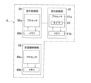
- FIG. 2 is a block diagram for explaining the configuration of the indoor air conditioning system 1 of FIG.
- the indoor air conditioning system 1 including the air conditioner 10 and the humidifier 106 includes a control unit 8.
- the humidifier 106 is instructed to operate by the indoor control unit 81 via the wireless LAN router 210 and the wireless LAN adapter 85.
- the control unit 8 has an indoor control unit 81, an outdoor control unit 86, and a humidifier control unit 89.
- the indoor air conditioning system 1 can instruct the air conditioner 10 and the humidifier 106 by using a communication terminal 230 such as a smartphone.
- a communication terminal 230 such as a smartphone.
- an instruction output from a communication terminal 230 such as a smartphone is transmitted to the air conditioner 10 and the humidifier 106 via the wireless LAN router 210 or via the Internet 240, the broadband router 220, and the wireless LAN router 210. ..
- FIG. 3 is a conceptual diagram showing an example of the air conditioner 10.
- the air conditioner 10 has an indoor unit 2, an outdoor unit 4, and a remote controller 15.
- the indoor unit 2 and the outdoor unit 4 are connected by refrigerant connecting pipes 11 and 12.
- the indoor unit 2, the outdoor unit 4, and the refrigerant connecting pipes 11 and 12 form a refrigerant circuit.
- the indoor unit 2 and the outdoor unit 4 are controlled by the control unit 8.
- the steam compression refrigeration cycle is repeated during the cooling operation, the heating operation, and the dehumidifying operation.
- the indoor unit 2 is installed in the room RM and performs air conditioning in the room RM.
- the indoor unit 2 is attached to the wall WL of the room RM.
- the indoor unit 2 is not limited to the type installed on the wall WL of the room RM.
- the indoor unit 2 may be installed on the ceiling CE or the floor FL, for example.
- FIG. 4 is a cross-sectional view showing an example of the configuration of the indoor unit 2 of the air conditioner 10.
- FIG. 5 is a diagram for explaining a refrigerant circuit of the air conditioner 10.
- the indoor unit 2 has an indoor heat exchanger 21. The indoor unit 2 exchanges heat with the indoor air by passing the indoor air (air in the room RM) through the indoor heat exchanger 21.
- the control unit 8 controls the indoor unit 2 so as to perform a cleaning operation, which is an operation for cleaning the indoor heat exchanger 21.
- a cleaning operation which is an operation for cleaning the indoor heat exchanger 21.
- the control unit 8 controls the humidifier 106 so as to raise the humidity in the room, and cleans the surface of the indoor heat exchanger 21 by generating dew condensation water on the surface of the indoor heat exchanger 21. ..
- the humidifier 6 may be started before the operation of the air conditioner 10 or at the same time as the operation of the air conditioner 10.
- control unit 8 first controls the humidifier 106 so that the humidity in the room reaches a predetermined humidity in the washing operation. In this case, after the room is brought to a predetermined humidity by the humidifier 106, the control unit 8 causes dew condensation water to be generated on the surface of the room heat exchanger 21 to clean the surface.
- the surface of the indoor heat exchanger 21 referred to here includes heat transfer fins 21a.
- the control unit 8 is realized by, for example, a microcomputer. For example, in the cleaning operation, the control unit 8 causes the humidifier 106 to perform a humidifying operation, and then causes the indoor unit 2 to perform a cleaning operation.
- the indoor air conditioning system 1 can raise the humidity in the room to a predetermined humidity by humidifying the washing operation.
- the indoor air conditioning system 1 can perform a cleaning operation in a state where the humidity in the room has risen to a predetermined humidity.
- the indoor air conditioning system 1 can clean the surface of the indoor heat exchanger 21 by causing sufficient dew condensation without being affected by indoor drying due to weather conditions and the like.
- the indoor unit 2 includes an indoor heat exchanger 21, an indoor fan 22, a casing 23, an air filter 24, a drain pan 26, a horizontal flap 27, and a vertical flap. (Not shown) and a discharge unit 29 are provided. Further, the indoor unit 2 includes an indoor temperature sensor 31, an indoor humidity sensor 32, a duct temperature sensor 33, a duct humidity sensor 34, and an indoor heat exchanger temperature sensor 35.
- the casing 23 has a suction port 23a at the upper portion and an outlet 23b at the lower portion.
- the indoor unit 2 drives the indoor fan 22 to suck in the indoor air from the suction port 23a and blow out the air that has passed through the indoor heat exchanger 21 from the air outlet 23b.
- the indoor fan 22 is arranged at a substantially central portion in the casing 23.
- the indoor fan 22 is, for example, a cross-flow fan.
- the indoor heat exchanger 21 is arranged upstream of the indoor fan 22 in the air flow path from the suction port 23a to the air outlet 23b.
- the indoor heat exchanger 21 has a plurality of heat transfer fins 21a and a plurality of heat transfer tubes 21b.
- the indoor air passes between the plurality of heat transfer fins 21a. Further, during heat exchange, air passes between the plurality of heat transfer fins 21a, and at the same time, the refrigerant flows through the heat transfer tube 21b.
- the heat transfer tube 21b is folded a plurality of times and penetrates one heat transfer fin 21a a plurality of times.
- the indoor heat exchanger 21 has a shape that opens downward so as to cover the upper part of the indoor fan 22 when viewed in the extending direction of the heat transfer tube 21b.
- a shape is referred to as a substantially ⁇ shape.
- the indoor heat exchanger 21 has a first heat exchange unit 21F far from the wall WL and a second heat exchange unit 21R close to the wall WL.
- the drain pan 26 is arranged under the front lower part and the rear lower part of the indoor heat exchanger 21 having a substantially ⁇ shape.
- the dew condensation generated in the first heat exchange section 21F of the indoor heat exchanger 21 is received by the drain pan 26 arranged in the lower front part of the indoor heat exchanger 21.
- the dew condensation generated in the second heat exchange unit 21R of the indoor heat exchanger 21 is received by the drain pan 26 arranged in the lower rear part of the indoor heat exchanger 21.
- Horizontal flap 27 A horizontal flap 27 and a vertical flap are arranged at the outlet 23b.
- the horizontal flap 27 changes the wind direction of the air blown from the outlet 23b up and down. Therefore, the horizontal flap 27 is configured so that the angle formed with the horizontal direction can be changed by the motor 27m.
- Air filter 24 An air filter 24 is arranged downstream of the suction port 23a in the casing 23 and upstream of the indoor heat exchanger 21.
- the air filter 24 is installed in the casing 23 so that substantially all the indoor air supplied to the indoor heat exchanger 21 passes through the air filter 24.
- the discharge unit 29 (see FIG. 2) is an active species generating device having a discharge unit inside.
- the discharge unit includes, for example, a needle-shaped electrode and a counter electrode, and a streamer discharge, which is a type of plasma discharge, is generated by applying a high voltage.
- Active species with high oxidative decomposition power are produced when a discharge occurs. These active species include, for example, fast electrons, ions, hydroxide radicals and excited oxygen molecules.
- the active species decomposes harmful components and odorous components in the air composed of small organic molecules such as ammonia, aldehydes and nitrogen oxides.
- the discharge unit 29 is arranged, for example, upstream of the air filter 24 or upstream of the indoor heat exchanger 21.
- (2-1-7) Indoor control unit 81 An indoor control unit 81, which is a component of the control unit 8, is arranged in the indoor unit 2. As shown in FIGS. 2 and 5, the indoor control unit 81 is connected to the motor 22 m of the indoor fan 22, the motor 27 m of the horizontal flap 27, and the reheat dehumidifying valve 28.
- the indoor control unit 81 can control the rotation speed of the motor 22m of the indoor fan 22, the rotation angle of the motor 27m of the horizontal flap 27, and the on / off of the reheat dehumidifying valve 28.
- FIG. 6 is a block diagram for explaining the configuration of the control unit 8.
- the room control unit 81 includes a processor 81a and a memory 81b.
- the processor 81a reads the control program for each operation stored in the memory 81b, and outputs a command required for each device.
- the memory 81b stores the instruction value from the outdoor control unit 86 at any time in addition to the control program for each operation.
- the processor 81a reads the data or the requested value stored in the memory 81b and calculates the necessary control value. Further, the processor 81a has a timer 83 inside.
- a CPU or GPU is adopted as the processor 81a.
- the above description is an example and is not limited to the above description.
- the indoor control unit 81 is connected to the motor 22 m of the indoor fan 22 shown in FIGS. 2 and 5, the motor 27 m of the horizontal flap 27, the reheat dehumidifying valve 28, and the speaker 82.
- the indoor control unit 81 is also connected to the outdoor control unit 86 arranged in the outdoor unit 4.
- the indoor control unit 81 receives a signal from the remote controller 15 and receives an instruction input from the remote controller 15.
- the remote controller 15 has a display screen 15a.
- the indoor control unit 81 can display various information on the display screen 15a of the remote controller 15.
- the indoor control unit 81 can use, for example, the display screen 15a to notify that the cleaning operation cannot be performed.
- the indoor control unit 81 can also notify via the speaker 82 that the cleaning operation cannot be performed.
- FIGS. 2 and 5 show an indoor temperature sensor 31, an indoor humidity sensor 32, and an indoor heat exchanger temperature sensor 35 among the sensors included in the indoor unit 2. These sensors are connected to the indoor control unit 81.
- the indoor control unit 81 detects the temperature of the indoor air by the indoor temperature sensor 31, and detects the relative humidity of the indoor air by the indoor humidity sensor 32.
- the indoor control unit 81 can detect the temperature of the refrigerant flowing in a specific place of the indoor heat exchanger 21 by the indoor heat exchanger temperature sensor 35.
- This specific location is, for example, the location of the heat transfer tube 21b to which the indoor heat exchanger temperature sensor 35 is attached.
- the indoor heat exchanger 21 has a reheat dehumidifying valve 28.
- the first heat exchange unit 21F and the second heat exchange unit 21R are connected via a reheat dehumidifying valve 28.
- the reheat dehumidifying valve 28 is fully opened during cooling operation, heating operation, and weak cooling / dehumidifying operation to allow the refrigerant to flow without depressurization, and close during reheat dehumidification to reduce the pressure of the refrigerant.
- valve mechanisms There are two types of valve mechanisms: a case where a decompression means is provided inside the valve body and a case where a decompression means such as a capillary tube is arranged in parallel with the valve.
- Outdoor unit 4 functions as a heat source unit that supplies heat energy to the indoor unit 2. As shown in FIGS. 2 and 5, the outdoor unit 4 includes a compressor 41, a four-way valve 42, an accumulator 43, an outdoor heat exchanger 44, an outdoor expansion valve 45, an outdoor fan 46, and a casing 47.
- the compressor 41, the four-way valve 42, the accumulator 43, the outdoor heat exchanger 44, the outdoor expansion valve 45, and the outdoor fan 46 are housed in the casing 47.
- the casing 47 has a suction port 47a (see FIG. 5) for sucking in outdoor air and an outlet 47b (see FIGS. 3 and 5) for blowing out the air after heat exchange.
- the suction port 47a is arranged on the rear side of the casing 47.
- the compressor 41 sucks in the gas refrigerant, compresses it, and discharges it.
- the compressor 41 is, for example, a variable displacement compressor whose operating capacity can be changed by adjusting the operating frequency of the motor 41 m with an inverter. The larger the operating frequency, the larger the operating capacity of the compressor 41.
- the four-way valve 42 switches the direction of the flow of the refrigerant in the refrigerant circuit 13.
- the four-way valve 42 has four ports.
- the first port P1 of the four-way valve 42 is connected to the discharge port of the compressor 41.
- the second port P2 of the four-way valve 42 is connected to the first inlet / outlet 44x of the outdoor heat exchanger 44.
- the third port P3 of the four-way valve 42 is connected to the accumulator 43.
- the fourth port P4 of the four-way valve 42 is connected to the second inlet / outlet 21y of the indoor heat exchanger 21.
- Outdoor heat exchanger 44 connects the second inlet / outlet 44y to the first inlet / outlet 45x of the outdoor expansion valve 45.
- the outdoor heat exchanger 44 exchanges heat between the refrigerant flowing into the inside from the first inlet / outlet 44x or the second inlet / outlet 44y and the outdoor air.
- Outdoor expansion valve 45 The outdoor expansion valve 45 connects the second inlet / outlet 45y to the first inlet / outlet 21x of the indoor heat exchanger 21.
- Outdoor control unit 86 In the outdoor unit 4, an outdoor control unit 86 constituting the control unit 8 is arranged. As shown in FIG. 6, the outdoor control unit 86 includes a control device 86a, a storage device 86b, and an arithmetic unit 86c.
- the control device 86a reads the control program stored in the storage device 86b and outputs a command required for each device.
- the storage device 86b stores the requested value from the indoor control unit 81 at any time in addition to each control program.
- the arithmetic unit 86c reads the data or the required value stored in the storage device 86b according to the command of the control device 86a, and calculates the necessary control value.
- a processor such as a CPU or GPU is adopted as the control device 86a and the arithmetic unit 86c.
- the above description is an example and is not limited to the above description.
- the outdoor control unit 86 is connected to the indoor control unit 81. Further, the outdoor control unit 86 is connected to the motor 41 m of the compressor 41, the four-way valve 42, and the motor 46 m of the outdoor fan 46.
- the outdoor control unit 86 can control the operating frequency of the motor 41 m of the compressor 41, the opening degree of the four-way valve 42, and the rotation speed of the motor 46 m of the outdoor fan 46.
- FIGS. 2 and 5 show an outside air temperature sensor 51, a discharge pipe temperature sensor 52, and an outdoor heat exchanger temperature sensor 53 among the sensors included in the outdoor unit 4. These sensors are connected to the outdoor control unit 86.
- the outdoor control unit 86 can detect the temperature of the outdoor air by the outside air temperature sensor 51. Further, the control unit 8 can detect the temperature of the refrigerant flowing through the discharge pipe (the refrigerant pipe connected to the discharge port of the compressor 41) by the discharge pipe temperature sensor 52, and the outdoor heat exchanger 53 by the outdoor heat exchanger 53. The temperature of the refrigerant flowing in 44 specific places can be detected.
- the outdoor control unit 86 monitors the state of the refrigerant in the refrigerant circuit 13 by means of a discharge pipe temperature sensor 52, an outdoor heat exchanger temperature sensor 53, an indoor heat exchanger temperature sensor 35, and the like.
- the refrigerant circuit 13 includes a compressor 41, a four-way valve 42, an accumulator 43, an outdoor heat exchanger 44, an outdoor expansion valve 45, and an indoor heat exchanger 21.
- Refrigerant circulates in the refrigerant circuit 13.
- the refrigerant include fluorocarbons such as R32 refrigerant and R410 refrigerant, carbon dioxide and the like.
- the refrigerant In the steam compression refrigeration cycle, the refrigerant is compressed by the compressor 41 to raise the temperature, and then the refrigerant dissipates heat in the outdoor heat exchanger 44 or the indoor heat exchanger 21. Further, in the steam compression type refrigeration cycle, the refrigerant is decompressed and expanded by the outdoor expansion valve 45, and then the refrigerant is endothermic by the indoor heat exchanger 21 or the outdoor heat exchanger 44.
- FIG. 7 is an exploded perspective view showing a configuration example of the humidifier 106 of FIG.
- the humidifier 106 includes a casing 110, a pre-filter 121, a dust collecting filter 122, a deodorizing filter 123, a blower fan 130, a humidifying filter unit 140, a water tray 150, and a tank 160.
- the casing 110 includes a main body 111 and a front panel 112.
- FIG. 8 is a perspective view showing the appearance of the humidifier 106 of FIG.
- the humidifier 106 has a suction port 113 at the boundary between the front panel 112 and the main body 111.
- the suction port 113 is provided on the lower portion and both sides of the front panel 112.
- the outlet 114 is provided on the upper part of the main body 111.
- An operation panel 115 is provided on the top surface of the main body 111.
- the operation panel 115 is provided with a plurality of operation buttons.
- the pre-filter 121 mainly removes large dust from the passing air.
- the dust collecting filter 122 mainly removes fine dust from the passing air.
- the deodorizing filter 123 contains, for example, activated carbon. The deodorizing filter 123 mainly removes odorous components from the passing air.
- the humidifying filter unit 140 has a humidifying rotor 141 including a humidifying filter 142.
- the humidifying rotor 141 is rotated by a motor 143 (see FIG. 2).
- the humidifying filter 142 receives the supply of water stored in the water tray 150 by rotating together with the humidifying rotor 141.
- the humidifying filter 142 that has been supplied with water supplies water to the passing air.
- the humidifying filter unit 140 stops humidification.
- the water tray 150 replenishes the water supplied to the humidifying filter 142 by receiving the water supply from the tank 160.
- the user replenishes the tank 160 with water.
- the humidifier control unit 89 includes a processor 89a and a memory 89b.
- the processor 89a reads the control program stored in the memory 89b and outputs a command required for each device.
- the memory 89b stores the requested value from the indoor control unit 81 at any time in addition to each control program.
- the processor 89a reads the data or the requested value stored in the memory 89b and calculates the necessary control value.
- processor 89a a processor such as a CPU or GPU is adopted.
- the above description is an example and is not limited to the above description.
- the control unit 8 can control the motor 143 via the humidifier control unit 89. Therefore, the control unit 8 can make the humidifier 106 perform the humidifying operation by turning on the motor 143, and stop the humidifying operation on the humidifier 106 by turning off the motor 143.
- the humidifier 106 includes an indoor temperature sensor 171, an indoor humidity sensor 172, and a water supply sensor 173.
- the indoor temperature sensor 171 and the indoor humidity sensor 172 and the water supply sensor 173 are connected to the humidifier control unit 89.
- control unit 8 can detect the temperature of the room air and the relative humidity by the room temperature sensor 171 and the room humidity sensor 172 via the humidifier control unit 89.
- the control unit 8 of the first embodiment may use the indoor temperature sensor 31 and the indoor humidity sensor 32 or the indoor temperature sensor 171 and the indoor humidity sensor 172 for control.
- the control unit 8 may use both sensors at the same time for control, for example, using the average value of the indoor temperature sensors 31 and 171 as the temperature of the indoor air. Further, the control unit 8 may use both sensors at the same time for control, for example, using the average value of the indoor humidity sensors 32 and 172 as the relative humidity of the indoor air.
- the normal operation of the indoor air conditioning system 1 includes, for example, cooling operation, heating operation, dehumidifying operation, ventilation operation, and air cleaning operation.
- the normal operation is an operation other than the washing operation.
- the normal operation is not limited to the above-mentioned cooling operation and heating operation.
- control unit 8 Before the start of the cooling operation, the control unit 8 is instructed by, for example, the remote controller 15 to perform the cooling operation and the target temperature. During the cooling operation, the control unit 8 switches the four-way valve 42 to the state shown by the solid line in FIG.
- the four-way valve 42 causes the refrigerant to flow between the first port P1 and the second port P2, and the refrigerant to flow between the third port P3 and the fourth port P4.
- the four-way valve 42 during the cooling operation causes the high-temperature and high-pressure gas refrigerant discharged from the compressor 41 to flow through the outdoor heat exchanger 44.
- the outdoor heat exchanger 44 heat is exchanged between the refrigerant and the outdoor air supplied by the outdoor fan 46.
- the refrigerant radiated by the outdoor heat exchanger 44 is decompressed by the outdoor expansion valve 45 and flows into the indoor heat exchanger 21.
- the indoor heat exchanger 21 heat exchange is performed between the refrigerant and the indoor air supplied by the indoor fan 22.
- the refrigerant absorbed by the heat exchange in the indoor heat exchanger 21 is sucked into the compressor 41 via the four-way valve 42 and the accumulator 43.
- the indoor air cooled by the indoor heat exchanger 21 is blown out from the indoor unit 2 to the room RM to cool the room.
- the indoor heat exchanger 21 functions as a refrigerant evaporator to warm the indoor air in the room RM, and the outdoor heat exchanger 44 functions as a refrigerant radiator.
- control unit 8 Before the start of the heating operation, the control unit 8 is instructed by, for example, the remote controller 15 to perform the heating operation and the target temperature. During the heating operation, the control unit 8 switches the four-way valve 42 to the state shown by the broken line in FIG.
- the four-way valve 42 causes the refrigerant to flow between the first port P1 and the fourth port P4, and the refrigerant to flow between the second port P2 and the third port P3.
- the four-way valve 42 during the heating operation causes the high-temperature and high-pressure gas refrigerant discharged from the compressor 41 to flow through the indoor heat exchanger 21.
- the indoor heat exchanger 21 heat exchange is performed between the refrigerant and the indoor air supplied by the indoor fan 22.
- the refrigerant radiated by the indoor heat exchanger 21 is decompressed by the outdoor expansion valve 45 and flows into the outdoor heat exchanger 44.
- the outdoor heat exchanger 44 heat is exchanged between the refrigerant and the indoor air supplied by the outdoor fan 46.
- the refrigerant absorbed by the heat exchange in the outdoor heat exchanger 44 is sucked into the compressor 41 via the four-way valve 42 and the accumulator 43.
- the indoor air heated by the indoor heat exchanger 21 is blown out from the indoor unit 2 to the room RM to heat the room.
- the indoor heat exchanger 21 functions as a refrigerant radiator to warm the indoor air in the room RM
- the outdoor heat exchanger 44 functions as a refrigerant evaporator.
- the first dehumidification operation is performed so that substantially the entire indoor heat exchanger 21 is in the evaporation area.
- a second dehumidification operation is performed in which at least a part of the windward side of the indoor heat exchanger 21 is set as an evaporation area, while the remaining part of the indoor heat exchanger 21 is set as a superheat area.
- the portion upstream of the reheat dehumidification valve 28 is the condensation region, while the portion downstream of the reheat dehumidification valve 28 is the evaporation region. Is done.
- control unit 8 switches the four-way valve 42 to the state shown by the solid line in FIG.
- the four-way valve 42 causes the refrigerant to flow between the first port P1 and the second port P2, and the refrigerant to flow between the third port P3 and the fourth port P4. Therefore, in the refrigerant circuit 13, the direction in which the refrigerant flows is the same during the dehumidifying operation and the cooling operation.
- the refrigeration cycle is also carried out in the refrigerant circuit 13 of the dehumidifying operation.
- the first dehumidifying operation has a high sensible heat capacity, which is the ability to change the room temperature.
- an evaporation region is not only when the entire indoor heat exchanger 21 is made into an evaporation region, but also only a part of the indoor heat exchanger 21 except for a part. Including when making the evaporation area.
- At least a part of the windward side of the first heat exchange section 21F is set as an evaporation region, while the remaining portion of the first heat exchange section 21F and the second heat exchange section 21R are set as a superheat zone.
- the control unit 8 controls the compressor 41 and the outdoor expansion valve 45 so that the evaporation area becomes a predetermined volume (for example, 2/3 of the total volume of the indoor heat exchanger 21) or less during the second dehumidification operation.
- the opening degree of the outdoor expansion valve 45 is usually smaller than the opening degree of the outdoor expansion valve 45 during the first dehumidifying operation.
- the sensible heat capacity of the second dehumidifying operation is lower than that of the first dehumidifying operation, it is possible to dehumidify the room while suppressing a decrease in room temperature when the heat load in the room is neither high nor low.
- the pressure is reduced by closing the reheat dehumidification valve 28.
- the first heat exchange unit 21F is set to the condensation region, while the second heat exchange unit 21R is set to the evaporation region.
- the first heat exchange unit 21F functions as a condensed region, it is possible to dehumidify the room while suppressing a decrease in room temperature as compared with the second dehumidification operation.
- control unit 8 Before the start of the blower operation, the control unit 8 is instructed to perform the blower operation, for example, from the remote controller 15. During the blowing operation, the control unit 8 stops the compressor 41 and stops the refrigerating cycle in the refrigerant circuit 13.
- the remote controller 15 may instruct the target air volume, or the indoor unit 2 may automatically select the target air volume.
- the control unit 8 controls the motor 22m of the indoor fan 22 so that the target air volume is reached.
- control unit 8 is configured to be able to increase the rotation speed in the order of the L tap, the M tap, and the H tap from the LL tap having the lowest rotation speed.
- the indoor air conditioning system 1 of the first embodiment performs an air cleaning operation using the discharge unit 29.
- the air cleaning operation is an operation of suppressing harmful components and / or odor components in the air.
- the air cleaning operation is, for example, an operation in which harmful components and / or odor components are suppressed by the decomposing power of streamer discharge.
- the first humidification operation is an operation of humidifying at the same time as heating.
- the control unit 8 controls the air conditioner 10 and the humidifier 106 so that the heating operation for the room RM by the air conditioner 10 and the humidification operation for the room RM by the humidifier 106 are simultaneously performed. ..
- the second humidification operation is an operation in which the heating operation in the first humidification operation is stopped and only the humidification operation is performed.
- the control unit 8 controls the air conditioner 10 and the humidifier 106 so that the room RM is humidified by the humidification operation of the humidifier 106.
- the heating operation is not performed, but the air conditioner 10 is used to blow air.
- the indoor air conditioning system 1 performs a cleaning operation using the humidifier 106.
- the humidifier 106 sucks in the indoor air from the suction port 113, moisturizes the indoor air, and blows it out into the room RM from the outlet 114.
- the indoor air conditioning system 1 performs the first humidification operation by using the air conditioner 10 and the humidifier 106.
- the control unit 8 causes the air conditioner 10 to perform the heating operation of the room RM, and at the same time causes the humidifier 106 to humidify the room RM.
- the control unit 8 stops the operation of the air conditioner 10 and causes the humidifier 106 to humidify.
- FIG. 9 is a flowchart for explaining the operation of the indoor air conditioning system 1.
- the control unit 8 is instructed to start the washing operation (in the case of manual start), and the control unit 8 automatically determines the start of the washing operation (automatically). In case of start).
- the indoor air conditioning system 1 of the first embodiment corresponds to both the case of manual start and the case of automatic start.
- the indoor air conditioning system 1 can also be configured to support either the manual start case or the automatic start case.
- Step S1 the control unit 8 determines whether or not there is an instruction for cleaning operation. When the control unit 8 determines that there is an instruction for the cleaning operation, the control unit 8 proceeds to step S2.
- the washing operation start button for instructing the washing operation of the remote controller 15 may be pressed.
- control unit 8 determines that there is no instruction for cleaning operation, the control unit 8 proceeds to step S11.
- Step S2 the control unit 8 controls the motor 27m so as to open the horizontal flap 27 and fix it at a predetermined angle in order to start the washing operation.
- the angle of the horizontal flap 27 is preferably an angle at which the air blown from the indoor unit 2 does not directly hit the person even if there is a person in the room RM.
- control unit 8 controls the discharge unit 29 so as to start the streamer discharge. If the horizontal flap 27 has already been opened before the process of step S2, it is maintained. Further, before the process of step S2, when the streamer discharge has already started, the state in which the streamer discharge is being performed is maintained. The streamer discharge ends when the cleaning operation ends.
- the indoor air conditioning system 1 can clean the indoor heat exchanger 21.
- the indoor air conditioning system 1 can also be configured so as to stop the discharge of the discharge unit 29 and perform the cleaning operation.
- step S3 the control unit 8 determines whether or not the humidity of the air in the room RM has reached the predetermined value AH1.
- the control unit 8 determines that the indoor humidity value has reached the predetermined value AH1 (predetermined humidity) not only when the indoor humidity value is the predetermined value AH1 but also when the indoor humidity value exceeds the predetermined value AH1. do.
- AH1 predetermined humidity
- the humidity absolute humidity may be used, but relative humidity may be substituted. When substituting with relative humidity, the detected value of relative humidity may be adjusted according to the atmospheric temperature, if necessary.
- the control unit 8 detects the indoor temperature by the indoor temperature sensor 31 and detects the relative humidity in the room by the indoor humidity sensor 32.
- the control unit 8 uses the air temperature value MT detected by the indoor temperature sensor 31 and the air relative humidity value MRH detected by the indoor humidity sensor 32 in the room RM.
- the absolute humidity of the air inside can be calculated.
- control unit 8 determines that the humidity in the room has reached the predetermined value AH1, the control unit 8 proceeds to step S4.
- control unit 8 determines that the humidity in the room has not reached the predetermined value AH1, the control unit 8 proceeds to step S31.
- Step S4 the control unit 8 starts the cleaning operation in step S4.
- the air conditioner 10 operates the indoor heat exchanger 21 as an evaporator, as in the cooling operation or the dehumidifying operation.
- the control unit 8 controls the air conditioner 10 so as to perform the same operation as the first dehumidifying operation.
- the control unit 8 has started counting by the timer 83 from the start of the washing operation.
- Step S5 the control unit 8 determines whether or not the predetermined time tt2 has elapsed since the washing operation was started.
- the control unit 8 determines that "a predetermined time tt2 has elapsed since the start of the washing operation"
- the control unit 8 ends the first dehumidifying operation and proceeds to step S6.
- control unit 8 determines that "the predetermined time tt2 has not elapsed since the start of the cleaning operation"
- the control unit 8 returns to step S4 and continues the cleaning operation.
- Step S6 The control unit 8 ends the cleaning operation in step S6.
- Step S11 Steps S1 to S6 are the main flow of operation. On the other hand, if the control unit 8 determines in step S1 that there is no instruction for the cleaning operation, the control unit 8 determines in step S11 whether or not the condition for starting the cleaning operation is satisfied.
- control unit 8 determines that "the conditions for starting the cleaning operation are satisfied"
- the control unit 8 proceeds to step S2.
- the conditions for shifting to the washing operation in step S11 will be described later in "(3-3) Conditions for shifting to the washing operation".
- control unit 8 determines that "the condition for starting the cleaning operation is not satisfied"
- the control unit 8 returns to step S1.
- Step S31 Further, if the control unit 8 determines in step S3 that the humidity in the room has not reached the predetermined value AH1, the control unit 8 determines in step S31 whether it is the first humidification operation or the first humidification operation based on the temperature in the room. 2 In order to select the humidification operation, it is determined whether or not the temperature detected by the room temperature sensor 31 is equal to or higher than the predetermined temperature T1.
- Step S32A If the control unit 8 determines in the previous step S31 that "the temperature detected by the indoor temperature sensor 31 is not equal to or higher than the predetermined temperature T1", the control unit 8 performs the above-mentioned first humidification operation in the step S32A.
- Step S32B If the control unit 8 determines in the previous step S31 that "the temperature detected by the indoor temperature sensor 31 is equal to or higher than the predetermined temperature T1", the control unit 8 performs the above-mentioned second humidification operation in the step S32B.
- the humidification operation by the humidifier 106 is performed.
- the humidification capacity is set to be equal to or higher than the maximum value of the humidification capacity that appears in the humidification operation in the normal operation.
- the washing operation the comfort of the room RM is not emphasized, but rather, the priority is given to finishing the washing operation quickly.
- the first humidification operation or the second humidification operation is performed with the maximum value or more of the humidification capacity appearing in the humidification operation of the normal operation so that the humidity in the room reaches the predetermined value AH1 quickly.
- the H tap is selected in the first humidification operation and the second humidification operation. ..
- the control unit 8 controls the air conditioner 10 together with the humidifier 106 so that the heating operation is performed at the same time as the humidification operation.
- the control unit 8 controls the air conditioner 10 so as to reach a target temperature preset for the cleaning operation.
- the heating operation performed by the air conditioner 10 in the washing operation is the same as the operation of the air conditioner 10 in the heating operation in the normal operation, so the description thereof is omitted here.
- Step S33 the control unit 8 determines in step S33 whether or not a predetermined time tt1 has elapsed from the start of humidification in either the first humidification operation or the second humidification operation. ..
- control unit 8 determines that the predetermined time tt1 has not elapsed, the control unit 8 returns to step S3 and continues the first humidification operation or the second humidification operation until the humidity in the room reaches the predetermined value AH1.
- control unit 8 determines that the predetermined time tt1 has elapsed, the control unit 8 proceeds to step S34.
- Step S34 If the control unit 8 determines in step S33 that "the predetermined time tt1 has elapsed", the control unit 8 notifies the abnormality in step S34 and returns to step S6.
- control unit 8 automatically determines whether or not to shift to the cleaning operation in step S11 of FIG.
- FIG. 10 is a flowchart showing an operation example of the control unit when automatically shifting to the cleaning operation. The process of the control unit 8 for determining the transition condition of the washing operation will be described with reference to FIG.
- step S41 the control unit 8 determines whether or not the operation mode is an operation other than the cleaning operation.
- the control unit 8 determines that "the operation mode is not an operation other than the cleaning operation (the operation mode is the cleaning operation)"
- the process proceeds to step S48 and the integrated drive time is reset.
- control unit 8 determines that the operation mode is an operation other than the cleaning operation, the control unit 8 proceeds to step S42.
- step S42 the control unit 8 determines whether or not the operation mode is an operation other than the cooling operation and the dehumidifying operation.
- the control unit 8 determines that "the indoor air conditioning system 1 is performing an operation other than the cooling operation and the dehumidifying operation", in other words, the indoor air conditioning system 1 performs a heating operation, a blowing operation, or an air cleaning operation. If so, the process proceeds to step S43.
- control unit 8 determines that "the indoor air conditioning system 1 is performing an operation other than the cooling operation and the dehumidifying operation" If the control unit 8 does not determine that "the indoor air conditioning system 1 is performing an operation other than the cooling operation and the dehumidifying operation", the process proceeds to step S421.
- Step S43 The control unit 8 counts the drive time of the indoor fan 22 in step S43.
- the processor 81a counts the drive time of the indoor fan 22, for example, by using the timer 83.
- the processor 81a stores the counted drive time in the memory 81b.
- the drive time of the indoor fan 22 is counted until the current operation is completed.
- the drive time of the indoor fan 22 is not counted.
- the drive time of the indoor fan 22 is counted in the first drive time and the second drive time.
- the first drive time is the drive time of the indoor fan 22 during the heating operation of the indoor unit 2.
- the second drive time is the drive time of the indoor fan 22 during the ventilation operation and the air purification operation.
- Step S421 On the other hand, if the control unit 8 does not determine that the indoor air conditioning system 1 is "operating other than the cooling operation or the dehumidifying operation" in the previous step S42, in other words, the indoor air conditioning system 1 is in the cooling operation or the dehumidifying operation. In this step S421, it is determined whether or not the operation time of the cooling operation or the dehumidifying operation is tt3 or more for the predetermined time.
- the operating time of the cooling operation or the dehumidifying operation is counted by the processor 81a using, for example, the timer 83.
- the processor 81a stores the counted operation time in the memory 81b.
- control unit 8 determines that "the operation time of the cooling operation or the dehumidification operation is tt3 or more for the predetermined time"
- the control unit 8 proceeds to step S48 and resets the integrated drive time of the indoor fan 22.
- the control unit 8 resets the integrated drive time when the indoor unit 2 that causes dew condensation is cooled or dehumidified by the indoor heat exchanger 21.
- control unit 8 determines that the operation time of the cooling operation and the dehumidification operation is less than the predetermined time tt3, the control unit 8 proceeds to step S44 without counting the drive time of the indoor fan 22.
- step S44 the control unit 8 determines whether or not the current operation has been completed. In other words, the control unit 8 controls so that the drive time of the indoor fan 22 when the indoor unit 2 is operating to cause dew condensation on the indoor heat exchanger 21 in normal operation is not included in the integrated drive time.
- control unit 8 determines that the current operation has ended, the control unit 8 proceeds to step S45.
- Step S45 The control unit 8 calculates the integrated drive time of the indoor fan 22 in step S45.
- the control unit 8 integrates the drive times stored in the memory 81b to calculate the integrated drive time.
- the integrated drive time is calculated by totaling the drive times of the indoor fans 22 for the heating operation, the ventilation operation, and the air cleaning operation.
- the method of calculating the integrated drive time is not limited to the method of simply summing the drive times of each operation.
- the control unit 8 can be configured to calculate the integrated drive time by weighting each type of operation.
- step S46 the control unit 8 determines whether or not the integrated drive time is equal to or longer than the predetermined drive time CT1. When the control unit 8 determines that the integrated drive time is equal to or longer than the predetermined drive time CT1, the control unit 8 proceeds to step S47.
- step S47 in FIG. 10 is an example of the determination in step S11 in FIG.
- the integrated drive time is equal to or longer than the predetermined drive time CT1, it is determined that the condition for shifting to the cleaning operation is satisfied.
- condition for shifting to the cleaning operation does not necessarily have to be that the integrated drive time is equal to or longer than the predetermined drive time CT1.
- a condition for shifting to the washing operation for example, a condition that the normal operation is stopped may be added.
- the control unit 8 returns to step S41 and repeats the step for integrating the integrated drive time when it is determined that the integrated drive time is less than the predetermined drive time CT1.
- Step S47 the control unit 8 sets a flag indicating that the transition condition to the washing operation is satisfied and stores it in the memory 81b.
- Step S48 The control unit 8 resets the integrated drive time in step S48.
- Step S49 If the indoor air conditioning system 1 is not stopped in step S49, the control unit 8 returns to step S41 and repeats the step for integrating the integrated drive time.
- step S41, step S48 and step S49 are repeated, so that the integrated drive time is not counted even if the indoor fan 22 is driven.
- Humidifier control in the washing operation Humidification operation by the humidifier 106 is performed in both the first humidification operation and the second humidification operation.
- the humidification operation performed in the first humidification operation and the second humidification operation is set so as to be equal to or more than the maximum value of the humidification capacity appearing in the humidification operation of the normal operation.
- FIG. 11A is an operation flowchart of the humidifier control in the washing operation.
- the flow after step S321 shows the control operation of the control unit 8 performed inside the steps S32A and S32B of FIG.
- step S321 the control unit 8 determines whether or not there is a humidification operation start command for the humidifier 106.
- the control unit 8 proceeds to step S322 when there is a command to start the humidifying operation of the humidifier 106.
- Step S322 the control unit 8 gives a notification prompting confirmation of the amount of residual water in the tank 160.
- the purpose of the notification is to prevent the tank 160 of the humidifier 106 from running out of water during the washing operation by prompting the confirmation of the amount of residual water in the tank 160 of the humidifier 106 when the indoor heat exchanger 21 is washed. This is to secure the condensed water (condensed water) required for cleaning.
- the control unit 8 displays a message prompting water supply to the tank 160 via the display screen 15a of the remote controller 15, or emits a voice message prompting water supply to the tank 160 via the speaker 82. , Etc. are adopted.
- Step S323 The control unit 8 determines in step S323 whether or not the cleaning operation start button is turned on. As a response from the user to the notification in step S322, the control unit 8 waits for the washing operation until the washing operation start button is turned on.
- the "washing operation start button" is provided on the remote controller 15, but instead, an instruction to start the washing operation can be given from a communication terminal 230 such as a smartphone.
- control unit 8 determines that the cleaning operation start button has been turned on.
- the control unit 8 proceeds to step S324.
- the control unit 8 waits for the cleaning operation.
- Step S324 The control unit 8 starts the operation of the humidifier 106 in step S324.
- the humidifying capacity of the humidifier 106 is set to L tap, M tap, and H tap in ascending order, and the H tap is selected in the first humidifying operation and the second humidifying operation during the washing operation.
- Step S325) the control unit 8 determines whether or not there is a stop command for the washing operation. This is because the user may want to stop the washing operation, and in such a case, it is necessary to forcibly end the washing operation even during the humidifying operation.
- control unit 8 When the control unit 8 is instructed to stop the cleaning operation, the control unit 8 proceeds to step S6 in FIG.
- the control unit 8 may notify the stop of the washing operation via a communication terminal 230 such as a smartphone or a remote controller 15.
- control unit 8 proceeds to step S33 in FIG. 9 when there is no stop command for the cleaning operation.
- step S32A of FIG. 9 As described above, in the first humidification operation of step S32A of FIG. 9 and the second humidification operation of step S32B, the controls of steps S321 to S325 are executed.
- step S322 of the flowchart of FIG. 11A a notification prompting confirmation of the residual water amount of the tank 160 is performed. It is not limited to.
- FIG. 11B is an operation flowchart of the humidifier control in the cleaning operation of the indoor air conditioning system according to the first modification.
- step S322 in FIG. 11A is replaced with step S322x.
- step S322x Since the other steps are the same as in FIG. 11A, only step S322x will be described here, and the description of the other steps will be omitted.
- Step S322x the control unit 8 gives a notification prompting water supply to the tank 160.
- the notification means is performed via the display screen 15a of the remote controller 15 or the speaker 82.
- the tank 160 may run out of water during the cleaning operation, and a satisfactory cleaning operation may not be performed. There is.
- step S323 of the flowchart of FIG. 11A it is determined whether or not the washing operation start button is turned on, but the present invention is not limited to this.
- FIG. 11C is an operation flowchart of the humidifier control in the cleaning operation of the indoor air conditioning system according to the second modification.
- step S322 in FIG. 11A is replaced by step S322y
- step S323 in FIG. 11A is replaced by step 323x.
- Step S322y the control unit 8 gives a notification prompting water supply to the tank 160, and at the same time, starts timing.
- the notification means is performed via the display screen 15a of the remote controller 15 or the speaker 82.
- Timekeeping is performed by a timer 83 built in the processor 81a of the indoor control unit 81.
- Step S323x the control unit 8 determines whether or not a predetermined time has elapsed after the notification in step 322y.
- the timer 83 activated in the previous step S322y performs the measurement of the predetermined time.
- the predetermined time can be set arbitrarily, but the initial setting is 5 minutes.
- the 5 minutes are assumed to be the time required for the user to supply water to the tank 160 after the notification prompting the water supply to the tank 160 is given.
- the control unit 8 proceeds to step 324 and starts the humidification operation when 5 minutes have elapsed after notifying the tank 160 to supply water.
- the tank 160 is urged to supply water, and then the user waits for the water to be supplied to the tank 160 to prevent the tank 160 from running out during the washing operation. ..
- FIG. 12 is an operation flowchart of the humidifier control in the cleaning operation of the indoor air conditioning system according to the third modification.
- the flow after step S51 shows the control operation of the control unit 8 performed inside the steps S352A and S32B of FIG.
- step S51 the control unit 8 determines whether or not there is a humidification operation start command for the humidifier 106.
- the control unit 8 proceeds to step S52 when there is a humidification operation start command for the humidifier 106.
- Step S52 The control unit 8 detects or estimates the amount of residual water in the tank 160 in step S52.
- the control unit 8 detects the residual water amount in the tank 160 by the water amount sensor.
- the control unit 8 estimates the amount of residual water in the tank 160 based on the operation history of the humidifier 106 and the water supply history to the tank 160.
- the processor 89a counts the water supply time to the tank 160 and the humidification operation time performed after the latest water supply, and stores them in the memory 89b.
- the processor 89a reads the humidification operation time from the memory 89b, calculates the amount of water consumed in the tank 160 from the humidification operation time, and further calculates the amount of residual water in the tank 160.
- the control unit 8 detects or estimates the amount of residual water in the tank 160, and then proceeds to step S53.
- step S53 the control unit 8 determines whether or not the amount of residual water in the tank 160 is less than the first predetermined amount.
- the process proceeds to step S54, and when it is determined that the residual water amount in the tank 160 is equal to or more than the first predetermined amount, the step S54 is performed. Proceed to S57.
- Step S54 the control unit 8 gives a notification to encourage water supply to the tank 160.
- the control unit 8 displays a message prompting water supply to the tank 160 via the display screen 15a of the remote controller 15, or emits a voice message prompting water supply to the tank 160 via the speaker 82. , Etc. are adopted.
- Step S55 the control unit 8 again detects or estimates the amount of residual water in the tank 160.
- the control unit 8 detects the residual water amount in the tank 160 by the water amount sensor.
- the control unit 8 estimates the amount of residual water in the tank 160 by the following method.
- the humidifier 106 has a switch mechanism in which the contacts are turned on by the gravity of the supplied tank 160.
- the on / off signal of the switch mechanism is input to the humidifier control unit 89 of the humidifier 106, the on / off operation of the switch mechanism can be detected by the humidifier control unit 89. Therefore, when the switch mechanism is switched on and off after the notification prompting the water supply to the tank 160, it can be estimated that the water supply to the tank 160 has been performed to the full water level (second predetermined amount or more).
- the control unit 8 detects or estimates the amount of residual water in the tank 160, and then proceeds to step S53.
- step S56 the control unit 8 determines whether or not the amount of residual water in the tank 160 is equal to or greater than the second predetermined amount.
- the second predetermined amount is set to a value larger than the first predetermined amount. This is because if the second predetermined amount and the first predetermined amount have the same value, the determination of less than that value and more than that value becomes unstable.
- step S57 When the control unit 8 determines that the amount of residual water in the tank 160 is equal to or greater than the second predetermined amount, the process proceeds to step S57, and when it is determined that the amount of residual water in the tank 160 is less than the second predetermined amount, the step S57 is performed. Return to S54.
- Step S57 The control unit 8 starts the humidification operation by the humidifier 106 in step S57.
- the humidifying capacity of the humidifier 106 is set to L tap, M tap, and H tap in ascending order, and the H tap is selected in the first humidifying operation and the second humidifying operation during the washing operation.
- Step S58 the control unit 8 determines whether or not there is a stop command for the washing operation. This is because the user may want to stop the washing operation, and in such a case, it is necessary to forcibly end the washing operation even during the humidifying operation.
- control unit 8 When the control unit 8 is instructed to stop the cleaning operation, the control unit 8 proceeds to step S6 in FIG.
- the control unit 8 may notify the stop of the washing operation via a communication terminal 230 such as a smartphone or a remote controller 15.
- control unit 8 proceeds to step S33 in FIG. 9 when there is no stop command for the cleaning operation.
- step S51 to S58 is executed in the first humidification operation of step S32A of FIG. 9 and the second humidification operation of step S32B.
- the control unit 8 has a second predetermined amount or more in which the residual water amount of the tank 160 is larger than the first predetermined amount.
- the washing operation may be started by omitting the notification for confirming the residual water amount of the tank 160 and the notification for prompting the water supply to the tank 160.
- the control unit 8 has an indoor control unit 81 that determines the execution of the cleaning operation.
- the control unit 8 notifies the user via the display screen 15a of the remote controller 15 or the speaker 82 that the cleaning operation is performed, and the rest of the tank 160.
- At least one of the notification prompting the confirmation of the amount of water and the notification prompting the water supply to the tank 160 is performed.
- the humidifier 106 detects or estimates the residual water amount of the tank 160 and determines that the residual water amount is equal to or less than the first predetermined amount, the humidifier 106 passes through the display screen 15a of the remote controller 15 or the speaker 82. The user is notified to urge the user to supply water to the tank 160.
- the control unit 8 estimates the residual water amount of the tank 160 based on the operation history of the humidifier 106 acquired by the humidifier control unit 89 and the water supply history to the tank 160, so that the residual water amount detecting means can be used. It is possible to adopt a humidifier that does not exist.
- control unit 8 starts the cleaning operation when a signal for starting the cleaning operation is input from the remote controller 15 in response to the notification.
- the humidifier 106 is instructed to operate by the indoor control unit 81 of the air conditioner 10 via the wireless LAN router 210 and the wireless LAN adapter 85. Met.
- FIG. 13 is a flowchart for explaining the operation of the indoor air conditioning system 1 according to the second embodiment. Hereinafter, the cleaning operation will be described with reference to the flowchart of FIG.
- steps S31 to S34 in FIG. 9 are replaced with steps S131 to S134.
- steps S1 to S6 will be omitted, and steps S131 to S134 will be described.
- Step S131 If the control unit 8 determines in step S3 that the humidity in the room has not reached the predetermined value AH1, the control unit 8 activates the counter in step S131 to set the number of notifications N for prompting humidification. Count.
- step S1 0 if the process proceeds from step S1 to step S131 in a state where the notification for prompting humidification has not been performed yet.
- step S132 the control unit 8 determines whether or not the number of times N of the notifications for prompting humidification has reached the predetermined number of times X.
- the control unit 8 proceeds to step S133.
- control unit 8 determines that the number of times N of notifications has reached the predetermined number of times X, the control unit 8 proceeds to step S6 to stop the washing operation.
- Step S133 the control unit 8 gives a notification to encourage humidification via the display screen 15a of the remote controller 15 or the speaker 82.
- the notification prompting humidification includes a notification prompting "start the humidifier 206 to perform humidification operation" and a notification prompting "operate to increase the humidifying capacity of the humidifier 206".
- the control unit 8 cannot grasp whether or not the humidifier 206 is operating.
- the message B "Please increase the humidifying capacity of the humidifier because the cleaning operation is performed" may be notified.
- the message C "Please restore the humidifying capacity of the humidifier because the cleaning operation is performed.” Is notified. You may.
- the message D "Since the cleaning operation is performed, please humidify for ⁇ hours.” May be notified.
- the ⁇ time is the time required for the washing operation.
- step S134 the control unit 8 determines whether or not a predetermined time ts1 has elapsed since the notification for prompting humidification was performed.
- the control unit 8 determines that the predetermined time ts1 has elapsed, the control unit 8 returns to step S3.
- the notification waits for the elapse of the predetermined time ts1 with the expectation that the user is performing the humidification operation by the humidifier 206. Then, it is determined by returning to step S3 whether or not the humidification operation is actually performed.
- control unit 8 repeats the routine of notifying the humidification prompt and waiting for the lapse of the predetermined time ts1 N times, and if the humidity in the room still does not reach the predetermined value AH1, the control unit 8 does not reach the predetermined value AH1.
- Reference numeral 8 presumes that the humidifier 206 is in a stopped state, and stops the washing operation.
- the control unit 8 may notify the stop of the washing operation via a communication terminal 230 such as a smartphone or a remote controller 15.
- the control unit 8 has an indoor control unit 81 that determines the execution of the cleaning operation.
- the control unit 8 notifies the user via the display screen 15a of the remote controller 15 or the speaker 82 that the cleaning operation is performed, and the rest of the tank 160.
- At least one of the notification prompting the confirmation of the amount of water and the notification prompting the water supply to the tank 160 is performed.
- control unit 8 starts the cleaning operation when a signal for starting the cleaning operation is input from the remote controller 15 in response to the notification.
- the indoor heat exchanger 21 functions as an evaporator and the moisture contained in the indoor air is condensed in the indoor heat exchanger 21 to condense the indoor heat exchanger 21.
- the explanation is based on the assumption that the dirt adhering to the surface is washed away.
- the cleaning operation is not limited to this, and the cleaning operation includes an operation of performing a freezing operation in which the surface temperature of the indoor heat exchanger 21 is set below the freezing point, and thawing after the freezing operation is completed to clean the indoor heat exchanger. Is done.
Landscapes
- Engineering & Computer Science (AREA)
- Chemical & Material Sciences (AREA)
- Combustion & Propulsion (AREA)
- Mechanical Engineering (AREA)
- General Engineering & Computer Science (AREA)
- Signal Processing (AREA)
- Physics & Mathematics (AREA)
- Fuzzy Systems (AREA)
- Mathematical Physics (AREA)
- Human Computer Interaction (AREA)
- Air Conditioning Control Device (AREA)
- Devices For Blowing Cold Air, Devices For Blowing Warm Air, And Means For Preventing Water Condensation In Air Conditioning Units (AREA)
- Air Humidification (AREA)
Abstract
本開示が解決しようとする課題は、洗浄運転に必要な結露量を確保することである。室内空調システム(1)では、制御部(8)は、洗浄運転の実施を決める室内制御部(81)を有している。室内空調システム(1)では、制御部(8)は、洗浄運転の実施が決まった場合に、リモートコントローラ(15)の表示画面(15a)またはスピーカ(82)を介してユーザーに洗浄運転が実施される旨の報知、タンク(160)の残水量の確認を促す報知、およびタンク(160)への給水を促す報知の、少なくとも1つを行う。その結果、洗浄運転中に加湿機の水切れを抑制し、洗浄に必要な凝縮水(結露水)を確保することができる。
Description
室内熱交換器の洗浄を行うための洗浄運転を行う室内空調システムに関する。
近年、室内機の室内熱交換器を自動で洗浄することができる空調機が市場に投入されるようになった。例えば、特許文献1(特開2010-014288号公報)に記載の空気調和機では、室内熱交換器のフィンの少なくも一部を着霜させる着霜運転を行い、その後除霜運転により除霜水を発生させてフィン表面に付着した汚れを除去する手段を備えている。
本開示は、熱交換器の洗浄に必要な湿度を確保し得る空気調和機を提供するものである。
第1観点の室内空調システムは、空調室内機と、加湿機と、制御部と、報知部とを備えている。空調室内機は、室内熱交換器を洗浄する洗浄運転を行う。洗浄運転は、室内熱交換器を蒸発器として機能させ室内空気に含まれる水分を室内熱交換器に凝縮させて室内熱交換器を洗浄する。加湿機は、室内の加湿を行う。制御部は、洗浄運転の実施を決める実施決定部を有している。制御部は、洗浄運転の実施が決まった場合に、報知部を介してユーザーに加湿機の貯留水に関する報知を行う。
この室内空調システムでは、室内熱交換器の洗浄運転を行う際に、加湿機の貯水量に関する報知を行うようにしたので、洗浄運転中に加湿機の水切れを抑制し、洗浄に必要な凝縮水(結露水)を確保することができる。
洗浄運転には、室内熱交換器の表面温度を氷点下にする凍結運転を行い、凍結運転の終了後に解凍させて室内熱交換器を洗浄する動作が含まれる。
第2観点の室内空調システムは、第1観点の室内空調システムであって、加湿機が、加湿用の水を貯留するタンクを有している。制御部は、洗浄運転の実施が決まった場合に、報知部を介してユーザーに洗浄運転が実施される旨の報知、および/またはタンクの残水量の確認を促す報知を行う。
第3観点の室内空調システムは、第1観点の室内空調システムであって、加湿機が、加湿用の水を貯留するタンクを有している。制御部は、洗浄運転の実施が決まった場合に、報知部を介してユーザーに洗浄運転が実施される旨の報知、および/またはタンクへの給水を促す報知を行う。
第4観点の室内空調システムは、第1観点から第3観点のいずれか1つの室内空調システムであって、加湿機が、加湿用の水を貯留するタンクを有している。加湿機は、タンクの残水量を検知または推定して、残水量が第1所定量以下であると判断したとき、報知部を介してユーザーにタンクへの給水を促す報知を行う。
この室内空調システムでは、残水量を正確に把握することができる。
第5観点の室内空調システムは、第4観点の室内空調システムであって、制御部が、履歴取得部をさらに有している。履歴取得部は、加湿機の運転履歴とタンクへの給水履歴とを取得する。制御部は、タンクに給水してから経過した加湿機の運転時間に基づき、残水量を推定する。
この室内空調システムでは、残水量検知手段がない加湿機の採用が可能となる。
第6観点の室内空調システムは、第2観点から第5観点の室内空調システムであって、制御部が、報知に対する応答があるまで洗浄運転を待機する。
この室内空調システムでは、洗浄に必要な凝縮水(結露水)が不足した状態で洗浄運転が開始されるのを抑制できる。
第7観点の室内空調システムは、第6観点の室内空調システムであって、洗浄運転の開始の指示を入力可能な操作部をさらに備えている。制御部は、報知に対して、操作部から洗浄運転を開始する信号が入力されたとき、洗浄運転を開始する。
第8観点の室内空調システムは、第4観点の室内空調システムであって、制御部が、残水量が第1所定量よりも大きい第2所定量以上であると判断したときは、洗浄運転を開始する。
<第1実施形態>
(1)全体構成
図1は、第1実施形態に係る室内空調システム1の構成の一例を示す概念図である。図1において、室内空調システム1は、空気調和機10と、空気清浄機能付き加湿機106(以後、加湿機106という。)を備えている。
(1)全体構成
図1は、第1実施形態に係る室内空調システム1の構成の一例を示す概念図である。図1において、室内空調システム1は、空気調和機10と、空気清浄機能付き加湿機106(以後、加湿機106という。)を備えている。
図1に示されているように、空気調和機10の室内機2と加湿機106とは、無線LANルータ210を介して接続されている。室内機2の室内制御部81(図2参照)には無線LANアダプタ85が接続されている。
ここでは、無線LANアダプタ85が室内機2に外付けされている場合が示されている。しかし、無線LANアダプタ85が室内機2に内蔵されてもよい。加湿機106の加湿機制御部89(図2参照)には、無線LANアダプタの機能が内蔵されている。
図2は、図1の室内空調システム1の構成を説明するためのブロック図である。図1および図2において、空気調和機10と加湿機106とからなる室内空調システム1は、制御部8を備えている。洗浄運転が行われるとき、加湿機106は、無線LANルータ210及び無線LANアダプタ85を介して、室内制御部81から動作を指示される。
制御部8は、室内制御部81と、室外制御部86と、加湿機制御部89とを有している。図1に示されているように、室内空調システム1は、スマートフォンなどの通信端末230を用いて、空気調和機10および加湿機106に指示することができる。例えば、スマートフォンなどの通信端末230から出力される指示は、無線LANルータ210を介してまたはインターネット240とブロードバンドルータ220と無線LANルータ210を介して、空気調和機10および加湿機106に送信される。
(2)空気調和機10
図3は、空気調和機10の一例を示す概念図である。図3において、空気調和機10は、室内機2と室外機4とリモートコントローラ15とを有している。室内機2と室外機4とは、冷媒連絡管11,12で接続されている。室内機2と室外機4と冷媒連絡管11,12とは冷媒回路を構成している。
図3は、空気調和機10の一例を示す概念図である。図3において、空気調和機10は、室内機2と室外機4とリモートコントローラ15とを有している。室内機2と室外機4とは、冷媒連絡管11,12で接続されている。室内機2と室外機4と冷媒連絡管11,12とは冷媒回路を構成している。
室内機2と室外機4は、制御部8により制御される。冷媒回路では、例えば、冷房運転、暖房運転及び除湿運転の際に、蒸気圧縮式冷凍サイクルが繰り返される。
室内機2は、部屋RMに設置され、部屋RMの中の空気調和を行う。第1実施形態では、室内機2が部屋RMの壁WLに取り付けられている。しかし、室内機2は、部屋RMの壁WLに設置されるタイプに限られるものではない。室内機2は、例えば、天井CEまたは床FLに設置されるものであってもよい。
図4は、空気調和機10の室内機2の構成の一例を示す断面図である。また、図5は、空気調和機10の冷媒回路を説明するための図である。図4および図5において、室内機2は、室内熱交換器21を有している。室内機2は、室内熱交換器21に室内空気(部屋RMの中の空気)を通して室内空気の熱交換を行う。
制御部8は、室内熱交換器21を洗浄する運転である洗浄運転を行うように室内機2を制御する。制御部8は、洗浄運転において、室内の湿度を上昇させるように加湿機106を制御すると共に、室内熱交換器21の表面で結露水を生じさせることによって室内熱交換器21の表面を洗浄する。加湿機6の起動は、空気調和機10の運転の前に行われても良いし、空気調和機10の運転と同時に行われてもよい。
制御部8は、洗浄運転において、先に、室内の湿度が所定湿度に達するように加湿機106を制御することが好ましい。この場合には、加湿機106で室内を所定湿度にした後に、制御部8は、室内熱交換器21の表面で結露水を生じさせて当該表面を洗浄する。ここでいう室内熱交換器21の表面には、伝熱フィン21aが含まれる。
制御部8は、例えば、マイクロコンピュータにより実現されるものである。制御部8は、例えば、洗浄運転では、先ず加湿機106に加湿動作を行わせ、次に室内機2に洗浄動作を行わせる。
気象条件などによって室内が乾燥した場合、室内が乾燥したままでは室内熱交換器21の表面に結露を生じさせて室内熱交換器21の表面を洗浄することが難しくなる。
しかし、気象条件などによって室内がもし乾燥していても、室内空調システム1は、洗浄運転の加湿で室内の湿度を所定湿度まで上げることができる。
室内空調システム1は、室内の湿度が所定湿度まで上がった状態で、洗浄動作を行うことができる。
このように、室内空調システム1は、気象条件などによる室内の乾燥に左右されず、室内熱交換器21の表面に十分な結露を生じさせて表面を洗浄することができる。
(2-1)室内機2
図2乃至図5に示されているように、室内機2は、室内熱交換器21と、室内ファン22と、ケーシング23と、エアフィルタ24と、ドレンパン26と、水平フラップ27と、垂直フラップ(図示せず)と、放電ユニット29とを備えている。また、室内機2は、室内温度センサ31と、室内湿度センサ32と、ダクト用温度センサ33と、ダクト用湿度センサ34と、室内熱交換器温度センサ35とを含む。
図2乃至図5に示されているように、室内機2は、室内熱交換器21と、室内ファン22と、ケーシング23と、エアフィルタ24と、ドレンパン26と、水平フラップ27と、垂直フラップ(図示せず)と、放電ユニット29とを備えている。また、室内機2は、室内温度センサ31と、室内湿度センサ32と、ダクト用温度センサ33と、ダクト用湿度センサ34と、室内熱交換器温度センサ35とを含む。
方向を説明する場合、図3及び図4に矢印で示されている向きに従って、「上」、「下」、「前」、「後」という表現を用いる。
(2-1-1)ケーシング23
ケーシング23は、上部に吸込口23aを有し、下部に吹出口23bを有している。室内機2は、室内ファン22を駆動して、室内の空気を吸込口23aから吸込み、室内熱交換器21を通過した空気を吹出口23bから吹き出す。
ケーシング23は、上部に吸込口23aを有し、下部に吹出口23bを有している。室内機2は、室内ファン22を駆動して、室内の空気を吸込口23aから吸込み、室内熱交換器21を通過した空気を吹出口23bから吹き出す。
(2-1-2)室内ファン22
室内ファン22は、図4に示すように、ケーシング23の中の略中央部分に配置されている。室内ファン22は、例えば、クロスフローファンである。吸込口23aから吹出口23bに向う空気流路において、室内ファン22の上流に室内熱交換器21が配置されている。
室内ファン22は、図4に示すように、ケーシング23の中の略中央部分に配置されている。室内ファン22は、例えば、クロスフローファンである。吸込口23aから吹出口23bに向う空気流路において、室内ファン22の上流に室内熱交換器21が配置されている。
(2-1-3)室内熱交換器21
室内熱交換器21は、複数の伝熱フィン21aと複数の伝熱管21bとを有している。室内空気は、複数の伝熱フィン21aの間を通過する。また、熱交換の際には、複数の伝熱フィン21aの間を空気が通過すると同時に、伝熱管21bの中を冷媒が流れる。伝熱管21bは、複数折り返されていて1つの伝熱フィン21aを複数回貫通する。
室内熱交換器21は、複数の伝熱フィン21aと複数の伝熱管21bとを有している。室内空気は、複数の伝熱フィン21aの間を通過する。また、熱交換の際には、複数の伝熱フィン21aの間を空気が通過すると同時に、伝熱管21bの中を冷媒が流れる。伝熱管21bは、複数折り返されていて1つの伝熱フィン21aを複数回貫通する。
室内熱交換器21は、伝熱管21bの延びる方向に見て、室内ファン22の上方を覆うように、下に向って開いた形状である。ここでは、このような形状を略Λ形状と呼ぶ。室内熱交換器21は、壁WLから遠い第1熱交換部21Fと壁WLに近い第2熱交換部21Rを有している。
略Λ形状を持つ室内熱交換器21の前方下部及び後方下部の下に、ドレンパン26が配置されている。室内熱交換器21のうちの第1熱交換部21Fで発生した結露は、室内熱交換器21の前方下部に配置されているドレンパン26で受け止められる。室内熱交換器21のうちの第2熱交換部21Rで発生した結露は、室内熱交換器21の後方下部に配置されているドレンパン26で受け止められる。
(2-1-4)水平フラップ27
吹出口23bには、水平フラップ27及び垂直フラップが配置されている。水平フラップ27は、吹出口23bから吹出される空気の風向を上下に変更する。そのため、水平フラップ27は、モータ27mにより、水平方向とのなす角を変更することができるように構成されている。
吹出口23bには、水平フラップ27及び垂直フラップが配置されている。水平フラップ27は、吹出口23bから吹出される空気の風向を上下に変更する。そのため、水平フラップ27は、モータ27mにより、水平方向とのなす角を変更することができるように構成されている。
(2-1-5)エアフィルタ24
ケーシング23の中の吸込口23aの下流且つ室内熱交換器21の上流には、エアフィルタ24が配置されている。室内熱交換器21に供給される室内空気が実質的に全てエアフィルタ24を通過するように、エアフィルタ24は、ケーシング23に設置されている。
ケーシング23の中の吸込口23aの下流且つ室内熱交換器21の上流には、エアフィルタ24が配置されている。室内熱交換器21に供給される室内空気が実質的に全てエアフィルタ24を通過するように、エアフィルタ24は、ケーシング23に設置されている。
したがって、エアフィルタ24の網目よりも大きな塵埃は、エアフィルタ24で除去されるので室内熱交換器21には到達しない。しかし、エアフィルタ24の網目よりも細かい塵埃及びオイルミストなど、エアフィルタ24を通過するものは室内熱交換器21に到達する。
(2-1-6)放電ユニット29
放電ユニット29(図2参照)は、内部に放電部を有する活性種生成装置である。放電部は、例えば、針状電極と対向電極とを備え、高電圧を印加することによりプラズマ放電の一種であるストリーマ放電を発生させる。酸化分解力の高い活性種は、放電発生の際に生成される。これらの活性種には、例えば、高速電子、イオン、水酸化ラジカル及び励起酸素分子が含まれる。活性種は、例えば、アンモニア類、アルデヒド類、窒素酸化物等の小さな有機分子からなる空気中の有害成分及び臭気成分を分解する。放電ユニット29は、例えば、エアフィルタ24の上流、または室内熱交換器21の上流に配置される。
放電ユニット29(図2参照)は、内部に放電部を有する活性種生成装置である。放電部は、例えば、針状電極と対向電極とを備え、高電圧を印加することによりプラズマ放電の一種であるストリーマ放電を発生させる。酸化分解力の高い活性種は、放電発生の際に生成される。これらの活性種には、例えば、高速電子、イオン、水酸化ラジカル及び励起酸素分子が含まれる。活性種は、例えば、アンモニア類、アルデヒド類、窒素酸化物等の小さな有機分子からなる空気中の有害成分及び臭気成分を分解する。放電ユニット29は、例えば、エアフィルタ24の上流、または室内熱交換器21の上流に配置される。
(2-1-7)室内制御部81
室内機2の中には、制御部8の構成要素である室内制御部81が配置されている。図2および図5に示されているように、室内制御部81は、室内ファン22のモータ22m、水平フラップ27のモータ27m及び再熱除湿弁28に接続されている。
室内機2の中には、制御部8の構成要素である室内制御部81が配置されている。図2および図5に示されているように、室内制御部81は、室内ファン22のモータ22m、水平フラップ27のモータ27m及び再熱除湿弁28に接続されている。
室内制御部81は、室内ファン22のモータ22mの回転数、水平フラップ27のモータ27mの回転角度及び再熱除湿弁28のオンオフを制御することができる。
図6は、制御部8の構成を説明するためのブロック図である。図6において、室内制御部81は、プロセッサ81aと、メモリ81bとを含む。
プロセッサ81aは、メモリ81bに記憶されている各運転の制御プログラムを読み取り、各機器に必要な指令を出力する。
メモリ81bは、各運転の制御プログラムの他、室外制御部86からの指示値を随時記憶する。
また、プロセッサ81aは、メモリ81bに記憶されたデータまたは要求値を読み取り、必要な制御値を演算する。さらに、プロセッサ81aは、内部にタイマ83を有している。
プロセッサ81aとして、CPUまたはGPUが採用される。上記の記載は、一例であって、上記記載内容に限定されるものではない。
室内制御部81は、図2および図5に記載されている室内ファン22のモータ22m、水平フラップ27のモータ27m、再熱除湿弁28の他、スピーカ82とも接続されている。また、室内制御部81は、室外機4の中に配置されている室外制御部86とも接続されている。
室内制御部81は、リモートコントローラ15からの信号を受信して、リモートコントローラ15から入力される指示を受け取る。リモートコントローラ15は、表示画面15aを有している。
室内制御部81は、リモートコントローラ15の表示画面15aに種々の情報を表示することができる。室内制御部81は、例えば、表示画面15aを使って、洗浄動作ができないことを報知することができる。
また、室内制御部81は、スピーカ82を介して洗浄動作ができないことを報知することもできる。
図2および図5には、室内機2が有するセンサのうち、室内温度センサ31と、室内湿度センサ32と、室内熱交換器温度センサ35が示されている。これらのセンサは、室内制御部81に接続されている。
室内制御部81は、室内温度センサ31により室内の空気の温度を検知し、室内湿度センサ32により室内の空気の相対湿度を検知する。
また、室内制御部81は、室内熱交換器温度センサ35により室内熱交換器21の特定の場所を流れる冷媒の温度を検知できる。この特定の場所は、例えば室内熱交換器温度センサ35が取り付けられている伝熱管21bの箇所である。
(2-1-8)再熱除湿弁28
図5に示されているように、室内熱交換器21は、再熱除湿弁28を有している。第1熱交換部21Fと第2熱交換部21Rは、再熱除湿弁28を介して接続されている。
図5に示されているように、室内熱交換器21は、再熱除湿弁28を有している。第1熱交換部21Fと第2熱交換部21Rは、再熱除湿弁28を介して接続されている。
再熱除湿弁28は、冷房運転、暖房運転、および弱冷房・除湿運転時には全開となり減圧することなく冷媒を流し、再熱除湿時には閉じることで冷媒を減圧する。
弁機構としては、弁本体内部に減圧手段を設けている場合と、弁と並列にキャピラリーチューブなどの減圧手段を配置している場合の2タイプがある。
(2-2)室外機4
室外機4は、室内機2に熱エネルギーを供給する熱源ユニットとして機能する。室外機4は、図2および図5に示されているように、圧縮機41と四方弁42とアキュムレータ43と室外熱交換器44と室外膨張弁45と室外ファン46とケーシング47とを含む。
室外機4は、室内機2に熱エネルギーを供給する熱源ユニットとして機能する。室外機4は、図2および図5に示されているように、圧縮機41と四方弁42とアキュムレータ43と室外熱交換器44と室外膨張弁45と室外ファン46とケーシング47とを含む。
圧縮機41と四方弁42とアキュムレータ43と室外熱交換器44と室外膨張弁45と室外ファン46とは、ケーシング47の中に収納されている。
(2-2-1)ケーシング47
ケーシング47は、室外の空気を吸い込む吸込口47a(図5参照)と、熱交換後の空気を吹き出す吹出口47b(図3および図5参照)とを有している。吸込口47aは、ケーシング47の後側に配置されている。
ケーシング47は、室外の空気を吸い込む吸込口47a(図5参照)と、熱交換後の空気を吹き出す吹出口47b(図3および図5参照)とを有している。吸込口47aは、ケーシング47の後側に配置されている。
(2-2-2)圧縮機41
圧縮機41は、ガス冷媒を吸入して圧縮して吐出する。圧縮機41は、例えば、モータ41mの運転周波数をインバータにより調整することで運転容量を変更することができる可変容量圧縮機である。運転周波数が大きいほど圧縮機41の運転容量が大きくなる。
圧縮機41は、ガス冷媒を吸入して圧縮して吐出する。圧縮機41は、例えば、モータ41mの運転周波数をインバータにより調整することで運転容量を変更することができる可変容量圧縮機である。運転周波数が大きいほど圧縮機41の運転容量が大きくなる。
(2-2-3)四方弁42
四方弁42は、冷媒回路13における冷媒の流れの向きを切り換える。四方弁42は、4つのポートを有している。四方弁42の第1ポートP1は、圧縮機41の吐出口に接続されている。四方弁42の第2ポートP2は、室外熱交換器44の第1出入口44xに接続されている。四方弁42の第3ポートP3は、アキュムレータ43に接続されている。四方弁42の第4ポートP4は、室内熱交換器21の第2出入口21yに接続されている。
四方弁42は、冷媒回路13における冷媒の流れの向きを切り換える。四方弁42は、4つのポートを有している。四方弁42の第1ポートP1は、圧縮機41の吐出口に接続されている。四方弁42の第2ポートP2は、室外熱交換器44の第1出入口44xに接続されている。四方弁42の第3ポートP3は、アキュムレータ43に接続されている。四方弁42の第4ポートP4は、室内熱交換器21の第2出入口21yに接続されている。
(2-2-4)アキュムレータ43
アキュムレータ43は、四方弁42の第3ポートP3と圧縮機41の吸入口との間に接続されている。アキュムレータ43では、圧縮機41に吸入される冷媒の気液分離が行われる。
アキュムレータ43は、四方弁42の第3ポートP3と圧縮機41の吸入口との間に接続されている。アキュムレータ43では、圧縮機41に吸入される冷媒の気液分離が行われる。
(2-2-5)室外熱交換器44
室外熱交換器44は、第2出入口44yを室外膨張弁45の第1出入口45xに接続している。室外熱交換器44は、第1出入口44xまたは第2出入口44yから内部に流入した冷媒と、室外の空気との間で熱交換を行う。
室外熱交換器44は、第2出入口44yを室外膨張弁45の第1出入口45xに接続している。室外熱交換器44は、第1出入口44xまたは第2出入口44yから内部に流入した冷媒と、室外の空気との間で熱交換を行う。
(2-2-6)室外膨張弁45
室外膨張弁45は、第2出入口45yを室内熱交換器21の第1出入口21xに接続している。
室外膨張弁45は、第2出入口45yを室内熱交換器21の第1出入口21xに接続している。
(2-2-7)室外制御部86
室外機4の中には、制御部8を構成している室外制御部86が配置されている。図6に示すように、室外制御部86は、制御装置86aと、記憶装置86bと、演算装置86cを含む。
室外機4の中には、制御部8を構成している室外制御部86が配置されている。図6に示すように、室外制御部86は、制御装置86aと、記憶装置86bと、演算装置86cを含む。
制御装置86aは、記憶装置86bに記憶されている制御プログラムを読み取り、各機器に必要な指令を出力する。
記憶装置86bは、各制御プログラムの他、室内制御部81からの要求値を随時記憶する。
演算装置86cは、制御装置86aの指令に従がって、記憶装置86bに記憶されたデータまたは要求値を読み取り、必要な制御値を演算する。
制御装置86a、演算装置86cとして、CPUまたはGPUといったプロセッサが採用される。上記の記載は、一例であって、上記記載内容に限定されるものではない。
室外制御部86は、室内制御部81と接続されている。また、室外制御部86は、圧縮機41のモータ41m、四方弁42及び室外ファン46のモータ46mと接続されている。
室外制御部86は、圧縮機41のモータ41mの運転周波数、四方弁42の開度及び室外ファン46のモータ46mの回転数を制御することができる。
図2および図5には、室外機4が有するセンサのうち、外気温度センサ51と、吐出管温度センサ52と、室外熱交換器温度センサ53とが示されている。これらのセンサは、室外制御部86に接続されている。
室外制御部86は、外気温度センサ51により室外の空気の温度を検知することができる。また、制御部8は、吐出管温度センサ52により吐出管(圧縮機41の吐出口に接続された冷媒配管)を流れる冷媒の温度を検知でき、室外熱交換器温度センサ53により室外熱交換器44の特定の場所を流れる冷媒の温度を検知できる。
室外制御部86は、冷凍サイクルの制御を行う際に、吐出管温度センサ52、室外熱交換器温度センサ53及び室内熱交換器温度センサ35などにより冷媒回路13の冷媒の状態を監視する。
冷媒回路13には、圧縮機41と、四方弁42と、アキュムレータ43と、室外熱交換器44と、室外膨張弁45と、室内熱交換器21とが含まれている。冷媒回路13には、冷媒が循環している。冷媒としては、例えば、R32冷媒及びR410冷媒などのフロン類、並びに二酸化炭素などがある。
蒸気圧縮式冷凍サイクルでは、冷媒が圧縮機41で圧縮されて昇温され、その後、室外熱交換器44または室内熱交換器21で冷媒が放熱する。また、蒸気圧縮式冷凍サイクルでは、室外膨張弁45で冷媒が減圧膨張され、その後、室内熱交換器21または室外熱交換器44で冷媒が吸熱する。
(3)加湿機106の構成
図7は、図1の加湿機106の構成例を示す分解斜視図である。図7において、加湿機106は、ケーシング110と、プレフィルタ121と、集塵フィルタ122と、脱臭フィルタ123と、送風ファン130と、加湿フィルタユニット140と、水トレー150と、タンク160とを備えている。ケーシング110は、本体部111と前面パネル112とを含んでいる。
図7は、図1の加湿機106の構成例を示す分解斜視図である。図7において、加湿機106は、ケーシング110と、プレフィルタ121と、集塵フィルタ122と、脱臭フィルタ123と、送風ファン130と、加湿フィルタユニット140と、水トレー150と、タンク160とを備えている。ケーシング110は、本体部111と前面パネル112とを含んでいる。
図8は、図1の加湿機106の外観を示す斜視図である。図8において、加湿機106は、前面パネル112と本体部111との境界に吸込口113を有している。吸込口113は、前面パネル112の下部と両サイドに設けられている。吹出口114は、本体部111の上部に設けられている。
図7および図8において、送風ファン130が駆動されると、吸込口113から吸い込まれた室内の空気は、プレフィルタ121、集塵フィルタ122、脱臭フィルタ123及び加湿フィルタユニット140を通過して、吹出口114から吹出される。
本体部111の天面には、操作パネル115が設けられている。操作パネル115には、複数の操作ボタンが設けられている。
プレフィルタ121は、通過する空気から、主に大きな塵埃を取り除く。集塵フィルタ122は、通過する空気から、主に微細な塵埃を取り除く。脱臭フィルタ123は、例えば、活性炭を含んでいる。脱臭フィルタ123は、通過する空気から、主に臭い成分を除去する。
加湿フィルタユニット140は、加湿フィルタ142を含む加湿ロータ141を有している。加湿ロータ141は、モータ143(図2参照)により回転させられる。加湿フィルタ142は、加湿ロータ141とともに回転することにより、水トレー150に溜められている水の供給を受ける。
水の供給を受けた加湿フィルタ142は、通過する空気に対して水分を供給する。モータ143が停止して加湿ロータ141の回転が止まると、加湿フィルタユニット140は加湿を停止する。
水トレー150は、タンク160から水の供給を受けることにより、加湿フィルタ142に供給する水の補充を行う。タンク160には、利用者が水を補給する。
図6に示すように、加湿機制御部89は、プロセッサ89aと、メモリ89bとを含む。
プロセッサ89aは、メモリ89bに記憶されている制御プログラムを読み取り、各機器に必要な指令を出力する。
メモリ89bは、各制御プログラムの他、室内制御部81からの要求値を随時記憶する。
また、プロセッサ89aは、メモリ89bに記憶されたデータまたは要求値を読み取り、必要な制御値を演算する。
プロセッサ89aとして、CPUまたはGPUといったプロセッサが採用される。上記の記載は、一例であって、上記記載内容に限定されるものではない。
制御部8は、加湿機制御部89を介して、モータ143を制御することができる。従って、制御部8は、モータ143をオンすることにより加湿機106に加湿動作を行わせ、モータ143をオフすることにより加湿機106に加湿動作を停止させることができる。
加湿機106は、図2に示されているように、室内温度センサ171と室内湿度センサ172と給水センサ173とを備えている。室内温度センサ171と室内湿度センサ172と給水センサ173とは、加湿機制御部89に接続されている。
従って、制御部8は、加湿機制御部89を介して、室内温度センサ171と室内湿度センサ172により、室内空気の温度と相対湿度とを検知することができる。第1実施形態の制御部8は、制御に室内温度センサ31と室内湿度センサ32若しくは室内温度センサ171と室内湿度センサ172を用いてもよい。
制御部8は、制御に、例えば室内温度センサ31,171の平均値を室内空気の温度として用いるなど、両センサを同時に用いてもよい。また、制御部8は、制御に、例えば室内湿度センサ32,172の平均値を室内空気の相対湿度として用いるなど、両センサを同時に用いてもよい。
(4)室内空調システム1の動作
(4-1)通常運転
室内空調システム1の通常運転には、例えば、冷房運転、暖房運転、除湿運転、送風運転、及び空気清浄運転がある。ここでは、通常運転が、洗浄運転以外の運転である。通常運転は、上述の冷房運転及び暖房運転などに限られるものではない。
(4-1)通常運転
室内空調システム1の通常運転には、例えば、冷房運転、暖房運転、除湿運転、送風運転、及び空気清浄運転がある。ここでは、通常運転が、洗浄運転以外の運転である。通常運転は、上述の冷房運転及び暖房運転などに限られるものではない。
(4-1-1)冷房運転
冷房運転の開始前に、制御部8には、例えば、リモートコントローラ15から冷房運転が指示されるとともに目標温度が指示される。冷房運転時には、制御部8は、四方弁42を、図5において実線で示されている状態に切り換える。
冷房運転の開始前に、制御部8には、例えば、リモートコントローラ15から冷房運転が指示されるとともに目標温度が指示される。冷房運転時には、制御部8は、四方弁42を、図5において実線で示されている状態に切り換える。
冷房運転時には、四方弁42は、第1ポートP1と第2ポートP2の間で冷媒を流し、第3ポートP3と第4ポートP4の間で冷媒を流す。冷房運転時の四方弁42は、圧縮機41から吐出される高温高圧のガス冷媒を室外熱交換器44に流す。
室外熱交換器44では、冷媒と、室外ファン46により供給される室外の空気との間で熱交換が行われる。室外熱交換器44で放熱した冷媒は、室外膨張弁45で減圧されて室内熱交換器21に流れ込む。
室内熱交換器21では、冷媒と室内ファン22により供給される室内の空気との間で熱交換が行われる。室内熱交換器21での熱交換により吸熱した冷媒は、四方弁42及びアキュムレータ43を経由して、圧縮機41に吸入される。
室内熱交換器21で冷やされた室内の空気が室内機2から部屋RMに吹出されることで、室内の冷房が行われる。
この空気調和機10では、冷房運転において、室内熱交換器21が冷媒の蒸発器として機能して部屋RMの中の室内空気を温め、室外熱交換器44が冷媒の放熱器として機能する。
(4-1-2)暖房運転
暖房運転の開始前に、制御部8には、例えば、リモートコントローラ15から暖房運転が指示されるとともに目標温度が指示される。暖房運転時には、制御部8は、四方弁42を、図5において破線で示されている状態に切り換える。
暖房運転の開始前に、制御部8には、例えば、リモートコントローラ15から暖房運転が指示されるとともに目標温度が指示される。暖房運転時には、制御部8は、四方弁42を、図5において破線で示されている状態に切り換える。
暖房運転時に、四方弁42は、第1ポートP1と第4ポートP4の間で冷媒を流し、第2ポートP2と第3ポートP3の間で冷媒を流す。暖房運転時の四方弁42は、圧縮機41から吐出される高温高圧のガス冷媒を室内熱交換器21に流す。
室内熱交換器21では、冷媒と、室内ファン22により供給される室内の空気との間で熱交換が行われる。室内熱交換器21で放熱した冷媒は、室外膨張弁45で減圧されて室外熱交換器44に流れ込む。
室外熱交換器44では、冷媒と室外ファン46により供給される室内の空気との間で熱交換が行われる。室外熱交換器44での熱交換により吸熱した冷媒は、四方弁42及びアキュムレータ43を経由して、圧縮機41に吸入される。
室内熱交換器21で温められた室内の空気が室内機2から部屋RMに吹出されることで、室内の暖房が行われる。
この空気調和機10では、暖房運転においては、室内熱交換器21が冷媒の放熱器として機能して部屋RMの中の室内空気を温め、室外熱交換器44が冷媒の蒸発器として機能する。
(4-1-3)除湿運転
除湿運転の開始前に、制御部8には、例えば、リモートコントローラ15から除湿運転が指示される。ここでは、除湿運転において複数のモードを選択できる場合について説明する。
除湿運転の開始前に、制御部8には、例えば、リモートコントローラ15から除湿運転が指示される。ここでは、除湿運転において複数のモードを選択できる場合について説明する。
制御部8には、リモートコントローラ15から、第1除湿モードと第2除湿モードと第3除湿モードの中のどのモードを選択したかの情報が送信される。
第1除湿モードでは、室内熱交換器21の実質的に全部を蒸発域にする第1除湿運転が行われる。
第2除湿モードでは、室内熱交換器21の風上側の少なくとも一部を蒸発域にする一方、室内熱交換器21の残りの部分を過熱域にする第2除湿運転が行われる。
第3除湿モードでは、室内熱交換器21において再熱除湿弁28よりも上流側の部分を凝縮域とする一方、再熱除湿弁28よりも下流側の部分を蒸発域とする第3除湿運転が行われる。
除湿運転時には、制御部8は、四方弁42を、図5において実線で示されている状態に切り換える。
除湿運転時には、四方弁42は、第1ポートP1と第2ポートP2の間で冷媒を流し、第3ポートP3と第4ポートP4の間で冷媒を流す。そのため、冷媒回路13において、除湿運転時と冷房運転時とで、冷媒の流れる向きは同じになる。除湿運転の冷媒回路13においても冷凍サイクルが実施される。
(4-1-3-1)第1除湿運転
第1除湿運転では、冷媒が冷媒回路13を循環するとき、制御部8は、再熱除湿弁28を全開にし、圧縮機41の運転周波数と室外膨張弁45の開度とを調整する。第1除湿運転では、室内熱交換器21の実質的に全部を蒸発域とする。
第1除湿運転では、冷媒が冷媒回路13を循環するとき、制御部8は、再熱除湿弁28を全開にし、圧縮機41の運転周波数と室外膨張弁45の開度とを調整する。第1除湿運転では、室内熱交換器21の実質的に全部を蒸発域とする。
これにより、第1除湿運転は、室内温度を変化させるための能力である顕熱能力が高くなる。
ここで、室内熱交換器21の実質的に全部を蒸発域にするとは、室内熱交換器21の全部を蒸発域にするときだけでなく、室内熱交換器21において一部を除いた部分だけを蒸発域にするときも含む。
この一部(例えば、室内熱交換器21の全容積の1/3以下の部分)だけが蒸発域とならないときとしては、例えば、室内環境などによって、室内熱交換器21の冷媒出口近傍の部分が過熱域となるときなどがある。
(4-1-3-2)第2除湿運転
第2除湿運転では、冷媒が冷媒回路13を循環するとき、制御部8は、再熱除湿弁28を全開にし、圧縮機41の運転周波数と室外膨張弁45の開度とを調整する。
第2除湿運転では、冷媒が冷媒回路13を循環するとき、制御部8は、再熱除湿弁28を全開にし、圧縮機41の運転周波数と室外膨張弁45の開度とを調整する。
第2除湿運転では、第1熱交換部21Fの風上側の少なくとも一部を蒸発域にする一方、第1熱交換部21Fの残りの部分及び第2熱交換部21Rを過熱域にする。
制御部8は、第2除湿運転中、蒸発域が所定容積(例えば、室内熱交換器21の全容積の2/3)以下となるように、圧縮機41および室外膨張弁45を制御する。
このとき、室外膨張弁45の開度は、通常、第1除湿運転中の室外膨張弁45の開度よりも小さくなる。
このとき、室外膨張弁45の開度は、通常、第1除湿運転中の室外膨張弁45の開度よりも小さくなる。
第2除湿運転は、第1除湿運転によりも顕熱能力が低くなるので、室内の熱負荷が高くも低くもないとき、室温の低下を抑制しつつ、室内の除湿を行える。
(4-1-3-3)第3除湿運転(再熱除湿運転)
第3除湿運転では、冷媒が冷媒回路13を循環するとき、制御部8は、再熱除湿弁28を閉じ、圧縮機41の運転周波数を調整すると共に、室外膨張弁45の開度を全開にする。
第3除湿運転では、冷媒が冷媒回路13を循環するとき、制御部8は、再熱除湿弁28を閉じ、圧縮機41の運転周波数を調整すると共に、室外膨張弁45の開度を全開にする。
第3除湿運転では、再熱除湿弁28を閉じることで減圧する。
第3除湿運転では、第1熱交換部21Fを凝縮域にする一方、第2熱交換部21Rを蒸発域にする。
第3除湿運転は、第1熱交換部21Fが凝縮域として機能するため、第2除湿運転よりも、室温の低下を抑制しつつ、室内の除湿を行える。
(4-1-4)送風運転
送風運転の開始前に、制御部8には、例えば、リモートコントローラ15から送風運転が指示される。送風運転時には、制御部8が、圧縮機41を停止させ、冷媒回路13における冷凍サイクルを停止させる。
送風運転の開始前に、制御部8には、例えば、リモートコントローラ15から送風運転が指示される。送風運転時には、制御部8が、圧縮機41を停止させ、冷媒回路13における冷凍サイクルを停止させる。
送風運転では、リモートコントローラ15から目標風量が指示される場合と、室内機2に目標風量を自動で選択させる場合がある。制御部8は、目標風量になるように、室内ファン22のモータ22mを制御する。
例えば、通常運転では、制御部8は、最も回転数の小さいLLタップから、Lタップ、Mタップ、Hタップの順に回転数を大きくすることができるように構成されている。
(4-1-5)空気清浄運転
第1実施形態の室内空調システム1は、放電ユニット29を用いて空気清浄運転を行う。ここで、空気清浄運転とは、空気中の有害成分及び/または臭気成分を抑制する運転である。
第1実施形態の室内空調システム1は、放電ユニット29を用いて空気清浄運転を行う。ここで、空気清浄運転とは、空気中の有害成分及び/または臭気成分を抑制する運転である。
空気清浄運転は、例えば、ストリーマ放電の分解力で有害成分及び/または臭気成分を抑える運転である。
(4-2)加湿運転
この室内空調システム1の場合には、加湿機106による水分の供給には、2つの方法が設定されている。制御部8は、第1加湿動作及び第2加湿動作の中から適切な運転を選択する。
この室内空調システム1の場合には、加湿機106による水分の供給には、2つの方法が設定されている。制御部8は、第1加湿動作及び第2加湿動作の中から適切な運転を選択する。
第1加湿動作は、暖房と同時に加湿をする運転である。第1加湿動作では、制御部8は、空気調和機10による部屋RMに対する暖房動作と加湿機106による部屋RMに対する加湿動作とを同時に行うように、空気調和機10と加湿機106とを制御する。
第2加湿動作は、第1加湿動作における暖房動作を止めて加湿動作だけをする運転である。第2加湿動作では、制御部8は、加湿機106の加湿動作によって部屋RMに対する加湿を行うように、空気調和機10と加湿機106とを制御する。第2加湿動作では、暖房動作は行われないが、空気調和機10による送風動作が行われる。
(4-3)洗浄運転
室内空調システム1は、加湿機106を用いて、洗浄運転を行う。室内空調システム1では、加湿機106が室内の空気を吸込口113から吸込み、室内の空気に水分を付与して吹出口114から部屋RMの中に吹き出す。
室内空調システム1は、加湿機106を用いて、洗浄運転を行う。室内空調システム1では、加湿機106が室内の空気を吸込口113から吸込み、室内の空気に水分を付与して吹出口114から部屋RMの中に吹き出す。
室内空調システム1は、空気調和機10と加湿機106を用いて第1加湿動作を行う。第1加湿動作において、制御部8は、空気調和機10に部屋RMの暖房運転を行わせ、同時に加湿機106に部屋RMに対する加湿を行わせる。室内空調システム1の第2加湿動作では、制御部8が、空気調和機10の運転を停止させ、加湿機106に加湿を行わせる。
図9は、室内空調システム1の動作を説明するためのフローチャートである。以下、洗浄運転を図9のフローチャートに沿って説明する。洗浄運転が開始される場合には、制御部8が洗浄運転を開始するように指示される場合(手動開始の場合)と、制御部8が洗浄運転の開始を自動的に判断する場合(自動開始の場合)がある。
第1実施形態の室内空調システム1は、手動開始の場合と自動開始の場合の両方に対応する。しかし、室内空調システム1を、手動開始の場合と自動開始の場合のうちのいずれか一方に対応するように構成することもできる。
(ステップS1)
制御部8は、ステップS1において、洗浄運転の指示の有無を判断する。制御部8は、洗浄運転の指示が有りと判断した場合、ステップS2へ進む。
制御部8は、ステップS1において、洗浄運転の指示の有無を判断する。制御部8は、洗浄運転の指示が有りと判断した場合、ステップS2へ進む。
手動開始の場合として、例えば、リモートコントローラ15の洗浄運転を指示するための洗浄運転開始ボタンが押される場合がある。
また、制御部8は、洗浄運転の指示が無いと判断した場合ステップS11へ進む。
(ステップS2)
制御部8は、ステップS2において、洗浄運転を開始するために、水平フラップ27を開いて所定の角度に固定するように、モータ27mを制御する。水平フラップ27の角度は、部屋RMに人が居たとしても、人に直接室内機2から吹出される空気が当たらない角度が好ましい。
制御部8は、ステップS2において、洗浄運転を開始するために、水平フラップ27を開いて所定の角度に固定するように、モータ27mを制御する。水平フラップ27の角度は、部屋RMに人が居たとしても、人に直接室内機2から吹出される空気が当たらない角度が好ましい。
また、制御部8は、ストリーマ放電を開始するように放電ユニット29を制御する。ステップS2の処理前に、既に水平フラップ27が開放されている場合にはそれを維持する。また、ステップS2の処理前に、既にストリーマ放電が開始されているときにはストリーマ放電を行っている状態を維持する。ストリーマ放電は、洗浄運転の終了によって終了する。
洗浄運転でストリーマ放電を行う場合には、室内空調システム1は、室内熱交換器21の清浄を行うことができる。ただし、放電ユニット29の放電を停止して洗浄動作を行うように、室内空調システム1を構成することもできる。
(ステップS3)
制御部8は、ステップS3において、部屋RMの中の空気の湿度が所定値AH1に達しているか否かを判断する。制御部8は、室内の湿度の値が所定値AH1である場合だけでなく、所定値AH1を超えている場合も、室内の湿度の値が所定値AH1(所定湿度)に達していると判断する。湿度は、絶対湿度を使用してもよいが、相対湿度で代用してもよい。相対湿度で代用する際は必要に応じて相対湿度の検出値を雰囲気温度に合わせて調整してもよい。
制御部8は、ステップS3において、部屋RMの中の空気の湿度が所定値AH1に達しているか否かを判断する。制御部8は、室内の湿度の値が所定値AH1である場合だけでなく、所定値AH1を超えている場合も、室内の湿度の値が所定値AH1(所定湿度)に達していると判断する。湿度は、絶対湿度を使用してもよいが、相対湿度で代用してもよい。相対湿度で代用する際は必要に応じて相対湿度の検出値を雰囲気温度に合わせて調整してもよい。
制御部8は、室内温度センサ31により室内の温度を検知し、室内湿度センサ32により室内の相対湿度を検知する。湿度に絶対湿度を使用する場合は、制御部8は、室内温度センサ31により検知した空気の温度の値MTと、室内湿度センサ32により検知した空気の相対湿度の値MRHとから、部屋RMの中の空気の絶対湿度を算出することができる。
制御部8は、室内の湿度が所定値AH1に達していると判断した場合、ステップS4に進む。
制御部8は、室内の湿度が所定値AH1に達していないと判断した場合、ステップS31に進む。
(ステップS4)
次に、制御部8は、ステップS4において、洗浄動作を開始する。洗浄動作では、空気調和機10は、冷房運転または除湿運転と同じく、室内熱交換器21を蒸発器として機能させる動作を行う。第1実施形態の室内空調システム1では、制御部8が、第1除湿運転と同じ動作を行うように空気調和機10を制御する。
次に、制御部8は、ステップS4において、洗浄動作を開始する。洗浄動作では、空気調和機10は、冷房運転または除湿運転と同じく、室内熱交換器21を蒸発器として機能させる動作を行う。第1実施形態の室内空調システム1では、制御部8が、第1除湿運転と同じ動作を行うように空気調和機10を制御する。
制御部8は、洗浄運転の開始から、タイマ83によりカウントを開始している。
(ステップS5)
次に、制御部8は、ステップS5において、洗浄運転を開始してから所定時間tt2が経過したか否かを判断する。制御部8は、「洗浄運転を開始してから所定時間tt2が経過した」と判断した場合、第1除湿運転を終了して、ステップS6へ進む。
次に、制御部8は、ステップS5において、洗浄運転を開始してから所定時間tt2が経過したか否かを判断する。制御部8は、「洗浄運転を開始してから所定時間tt2が経過した」と判断した場合、第1除湿運転を終了して、ステップS6へ進む。
制御部8は、「洗浄運転を開始してから所定時間tt2が経過していない」と判断した場合、ステップS4へ戻って、洗浄動作を継続する。
(ステップS6)
制御部8は、ステップS6において、洗浄運転を終了する。
制御部8は、ステップS6において、洗浄運転を終了する。
(ステップS11)
ステップS1からステップS6が動作のメインフローである。一方、先のステップS1において、制御部8が洗浄運転の指示が無いと判断した場合、制御部8は、ステップS11において、洗浄運転を開始する条件が満たされたか否かを判断する。
ステップS1からステップS6が動作のメインフローである。一方、先のステップS1において、制御部8が洗浄運転の指示が無いと判断した場合、制御部8は、ステップS11において、洗浄運転を開始する条件が満たされたか否かを判断する。
制御部8は、「洗浄運転を開始する条件が満たされている」と判断した場合、ステップS2へ進む。ステップS11の洗浄運転への移行条件については、後の「(3-3)洗浄運転への移行条件」で説明する。
また、制御部8は、「洗浄運転を開始する条件が満たされていない」と判断した場合、ステップS1に戻る。
(ステップS31)
また、先のステップS3において、制御部8が室内の湿度が所定値AH1に達していないと判断した場合、制御部8は、ステップS31において、室内の温度に基づいて、第1加湿動作か第2加湿動作かを選択するために、室内温度センサ31で検知された温度が所定温度T1以上であるか否かを判断する。
また、先のステップS3において、制御部8が室内の湿度が所定値AH1に達していないと判断した場合、制御部8は、ステップS31において、室内の温度に基づいて、第1加湿動作か第2加湿動作かを選択するために、室内温度センサ31で検知された温度が所定温度T1以上であるか否かを判断する。
(ステップS32A)
先のステップS31において、制御部8が「室内温度センサ31で検知された温度が所定温度T1以上ではない」と判断した場合、制御部8はステップS32Aにおいて、上述の第1加湿動作を行う。
先のステップS31において、制御部8が「室内温度センサ31で検知された温度が所定温度T1以上ではない」と判断した場合、制御部8はステップS32Aにおいて、上述の第1加湿動作を行う。
(ステップS32B)
先のステップS31において、制御部8が「室内温度センサ31で検知された温度が所定温度T1以上である」と判断した場合、制御部8はステップS32Bにおいて、上述の第2加湿動作を行う。
先のステップS31において、制御部8が「室内温度センサ31で検知された温度が所定温度T1以上である」と判断した場合、制御部8はステップS32Bにおいて、上述の第2加湿動作を行う。
第1加湿動作でも、第2加湿動作でも、加湿機106による加湿の動作が行われる。第1加湿動作及び第2加湿動作で行われる加湿動作では、通常運転の加湿運転で出現する加湿能力の最大値以上になるように設定されている。洗浄運転では、部屋RMの快適性を重要視しておらず、むしろ、洗浄運転を速く終了することを優先している。
そのため、洗浄運転では、室内の湿度が所定値AH1に早く到達するように、通常運転の加湿運転で出現する加湿能力の最大値以上で、第1加湿動作または第2加湿動作が行われる。
例えば、通常運転の加湿運転の加湿能力が低い方から順に、Lタップ、Mタップ、Hタップと設定されている場合には、第1加湿動作及び第2加湿動作では、Hタップが選択される。
第1加湿動作では、制御部8は、加湿動作と同時に暖房動作をするように、加湿機106とともに空気調和機10を制御する。制御部8は、洗浄運転のために予め設定されている目標温度になるように空気調和機10を制御する。
洗浄運転で空気調和機10が行う暖房動作は、通常運転の暖房運転での空気調和機10の動作と同じであるので、ここでは説明を省略する。
(ステップS33)
次に、制御部8は、第1加湿動作、および2加湿動作のいずれの動作であっても、ステップS33において、加湿の開始から所定時間tt1が経過したか否かを制御部8が判断する。
次に、制御部8は、第1加湿動作、および2加湿動作のいずれの動作であっても、ステップS33において、加湿の開始から所定時間tt1が経過したか否かを制御部8が判断する。
制御部8は、所定時間tt1が経過していないと判断した場合、ステップS3に戻って、室内の湿度が所定値AH1に達するまで、第1加湿動作または第2加湿動作を継続する。
制御部8は、所定時間tt1が経過していると判断した場合、ステップS34へ進む。
(ステップS34)
先のステップS33において、制御部8が「所定時間tt1が経過している」と判断した場合、制御部8は、ステップS34において、異常を報知してステップS6へ戻る。
先のステップS33において、制御部8が「所定時間tt1が経過している」と判断した場合、制御部8は、ステップS34において、異常を報知してステップS6へ戻る。
(洗浄運転への移行条件)
室内空調システム1は、制御部8が、図9のステップS11において、自動的に、洗浄運転へ移行するか否かの判断を行う。
室内空調システム1は、制御部8が、図9のステップS11において、自動的に、洗浄運転へ移行するか否かの判断を行う。
図10は、洗浄運転に自動的に移行する際の制御部の動作例を示すフローチャートである。洗浄運転の移行条件を判断するための制御部8の処理について、図10に沿って説明する。
(ステップS41)
制御部8は、ステップS41において、運転モードが洗浄運転以外の運転か否かの判断を行う。制御部8は、「運転モードが洗浄運転以外の運転でない(運転モードが洗浄運転である)」と判断した場合は、ステップS48へ進み、積算駆動時間をリセットする。
制御部8は、ステップS41において、運転モードが洗浄運転以外の運転か否かの判断を行う。制御部8は、「運転モードが洗浄運転以外の運転でない(運転モードが洗浄運転である)」と判断した場合は、ステップS48へ進み、積算駆動時間をリセットする。
制御部8は、「運転モードが洗浄運転以外の運転である」と判断場合には、制御部8は、ステップS42へ進む。
(ステップS42)
次に、制御部8は、ステップS42において、運転モードが冷房運転および除湿運転以外の運転であるか否かの判断を行う。制御部8は、「室内空調システム1が冷房運転および除湿運転以外の運転を行っている」と判断した場合、言い換えれば、室内空調システム1が暖房運転、送風運転、または空気清浄運転を行っている場合には、ステップS43に進む。
次に、制御部8は、ステップS42において、運転モードが冷房運転および除湿運転以外の運転であるか否かの判断を行う。制御部8は、「室内空調システム1が冷房運転および除湿運転以外の運転を行っている」と判断した場合、言い換えれば、室内空調システム1が暖房運転、送風運転、または空気清浄運転を行っている場合には、ステップS43に進む。
また、制御部8は、「室内空調システム1が冷房運転および除湿運転以外の運転を行っている」と判断しない場合、ステップS421へ進む。
(ステップS43)
制御部8は、ステップS43において、室内ファン22の駆動時間をカウントする。
制御部8は、ステップS43において、室内ファン22の駆動時間をカウントする。
室内ファン22の駆動時間のカウントは、例えば、タイマ83を用いてプロセッサ81aが行う。プロセッサ81aは、カウントした駆動時間をメモリ81bに記憶させる。現在の運転が終了するまで、室内ファン22の駆動時間のカウントが行われる。
例えば、暖房運転中であっても、部屋RMの温度が目標温度に達していて、圧縮機41及び室内ファン22などが停止しているときは、室内ファン22の駆動時間のカウントを行わない。
室内ファン22の駆動時間のカウントが行われるのは、第1駆動時間と第2駆動時間である。第1駆動時間は、室内機2の暖房運転のときの室内ファン22の駆動時間である。
第2駆動時間は、送風運転、及び空気清浄運転のときの室内ファン22の駆動時間である。
(ステップS421)
一方、先のステップS42において、制御部8が、室内空調システム1が「冷房運転または除湿運転以外の運転を行っている」と判断しない場合、言い換えれば、室内空調システム1が冷房運転または除湿運転を行っている場合には、このステップS421において、冷房運転または除湿運転の運転時間が所定時間tt3以上になっているか否かの判断を行う。
一方、先のステップS42において、制御部8が、室内空調システム1が「冷房運転または除湿運転以外の運転を行っている」と判断しない場合、言い換えれば、室内空調システム1が冷房運転または除湿運転を行っている場合には、このステップS421において、冷房運転または除湿運転の運転時間が所定時間tt3以上になっているか否かの判断を行う。
冷房運転または除湿運転の運転時間は、例えば、タイマ83を用いてプロセッサ81aがカウントする。プロセッサ81aは、カウントした運転時間をメモリ81bに記憶させる。
制御部8は、「冷房運転または除湿運転の運転時間が所定時間tt3以上である」と判断した場合、制御部8は、ステップS48に進み、室内ファン22の積算駆動時間をリセットする。制御部8は、室内熱交換器21で結露を生じる室内機2の冷房運転または除湿運転をした場合に、積算駆動時間をリセットする。
また、制御部8は、冷房運転および除湿運転の運転時間が所定時間tt3未満であると判断した場合、制御部8は、室内ファン22の駆動時間のカウントを行わずに、ステップS44へ進む。
(ステップS44)
制御部8は、ステップS44において、現在の運転が終了したか否かを判断する。言い換えると、制御部8は、通常運転で室内機2が室内熱交換器21で結露を生じる運転をしているときの室内ファン22の駆動時間を、積算駆動時間に算入しない制御をする。
制御部8は、ステップS44において、現在の運転が終了したか否かを判断する。言い換えると、制御部8は、通常運転で室内機2が室内熱交換器21で結露を生じる運転をしているときの室内ファン22の駆動時間を、積算駆動時間に算入しない制御をする。
制御部8は、現在の運転が終了したと判断した場合、制御部8は、ステップS45へ進む。
(ステップS45)
制御部8は、ステップS45において、室内ファン22の積算駆動時間を算出する。制御部8は、メモリ81bに記憶されている駆動時間を積算して積算駆動時間を算出する。
制御部8は、ステップS45において、室内ファン22の積算駆動時間を算出する。制御部8は、メモリ81bに記憶されている駆動時間を積算して積算駆動時間を算出する。
ここでは、暖房運転、送風運転、及び空気清浄運転の室内ファン22の各駆動時間を合計して積算駆動時間を算出する。しかし、積算駆動時間の算出方法は、単に各運転の駆動時間を合計する方法に限られない。例えば、運転の種類ごとに重み付けを行って積算駆動時間を算出するように、制御部8を構成することもできる。
(ステップS46)
制御部8は、ステップS46において、積算駆動時間が所定駆動時間CT1以上になっているか否かを判断する。制御部8は、「積算駆動時間が所定駆動時間CT1以上になっていると判断した場合、制御部8は、ステップS47に進む。
制御部8は、ステップS46において、積算駆動時間が所定駆動時間CT1以上になっているか否かを判断する。制御部8は、「積算駆動時間が所定駆動時間CT1以上になっていると判断した場合、制御部8は、ステップS47に進む。
図10のステップS47の決定は、図9のステップS11の判断の一例である。ここでは、積算駆動時間が所定駆動時間CT1以上になっていれば、洗浄運転への移行条件が満たされたと判断している。
しかし、洗浄運転への移行条件は、積算駆動時間が所定駆動時間CT1以上になっていることに限らなくてもよい。洗浄運転への移行条件として、例えば、通常運転が停止されているという条件が加えられてもよい。
制御部8は、「積算駆動時間が所定駆動時間CT1未満であると判断した場合、ステップS41に戻って、積算駆動時間の積算のためのステップを繰り返す。
(ステップS47)
制御部8は、ステップS47において、洗浄運転への移行条件が満たされたことを示すフラグをたて、メモリ81bに記憶する。
制御部8は、ステップS47において、洗浄運転への移行条件が満たされたことを示すフラグをたて、メモリ81bに記憶する。
(ステップS48)
制御部8は、ステップS48において、積算駆動時間をリセットする。
制御部8は、ステップS48において、積算駆動時間をリセットする。
(ステップS49)
制御部8は、ステップS49において、室内空調システム1が停止していなければ、ステップS41に戻って、積算駆動時間の積算のためのステップを繰り返す。
制御部8は、ステップS49において、室内空調システム1が停止していなければ、ステップS41に戻って、積算駆動時間の積算のためのステップを繰り返す。
洗浄運転の場合には、ステップS41、ステップS48およびステップS49を繰り返すので、たとえ室内ファン22が駆動されても積算駆動時間はカウントされない。
(4-4)洗浄運転における加湿機制御
第1加湿動作でも、第2加湿動作でも、加湿機106による加湿の動作が行われる。第1加湿動作および第2加湿動作で行われる加湿動作は、通常運転の加湿運転で出現する加湿能力の最大値以上になるように設定されている。
第1加湿動作でも、第2加湿動作でも、加湿機106による加湿の動作が行われる。第1加湿動作および第2加湿動作で行われる加湿動作は、通常運転の加湿運転で出現する加湿能力の最大値以上になるように設定されている。
図11Aは、洗浄運転における加湿機制御の動作フローチャートである。図11Aにおいて、ステップS321以降のフローは、図9のステップS32AおよびステップS32Bの内部で行われている制御部8の制御動作を示している。
(ステップS321)
制御部8は、ステップS321において、加湿機106の加湿運転開始指令の有無を判断する。制御部8は、加湿機106の加湿運転開始指令が有るときは、ステップS322へ進む。
制御部8は、ステップS321において、加湿機106の加湿運転開始指令の有無を判断する。制御部8は、加湿機106の加湿運転開始指令が有るときは、ステップS322へ進む。
(ステップS322)
制御部8は、ステップS322において、タンク160の残水量の確認を促す報知を行う。
制御部8は、ステップS322において、タンク160の残水量の確認を促す報知を行う。
報知の目的は、室内熱交換器21の洗浄運転を行う際に、加湿機106のタンク160の残水量の確認を促すことによって、洗浄運転中に加湿機106のタンク160の水切れを抑制し、洗浄に必要な凝縮水(結露水)を確保するためである。
報知の手段としては、制御部8がリモートコントローラ15の表示画面15aを介してタンク160への給水を促すメッセージを表示する、或いは、スピーカ82を介してタンク160への給水を促す音声メッセージを発する、などの手段が採用される。
(ステップS323)
制御部8は、ステップS323において、洗浄運転開始ボタンがオンしたか否かを判断する。制御部8は、ステップS322の報知に対するユーザーからの応答として、洗浄運転開始ボタンがオンするまで洗浄運転を待機している。「洗浄運転開始ボタン」は、リモートコントローラ15に設けられるが、それに替えて、スマートフォンなどの通信端末230から洗浄運転開始の指示をすることもできる。
制御部8は、ステップS323において、洗浄運転開始ボタンがオンしたか否かを判断する。制御部8は、ステップS322の報知に対するユーザーからの応答として、洗浄運転開始ボタンがオンするまで洗浄運転を待機している。「洗浄運転開始ボタン」は、リモートコントローラ15に設けられるが、それに替えて、スマートフォンなどの通信端末230から洗浄運転開始の指示をすることもできる。
制御部8は、洗浄運転開始ボタンがオンしたと判断したときはステップS324へ進む。一方、制御部8は、洗浄運転開始ボタンがオンしていないと判断したときは、洗浄運転を待機する。
(ステップS324)
制御部8は、ステップS324において、加湿機106の運転を開始する。加湿機106の加湿能力は低い方から順に、Lタップ、Mタップ、Hタップと設定されており、洗浄運転時における第1加湿動作および第2加湿動作では、Hタップが選択される。
制御部8は、ステップS324において、加湿機106の運転を開始する。加湿機106の加湿能力は低い方から順に、Lタップ、Mタップ、Hタップと設定されており、洗浄運転時における第1加湿動作および第2加湿動作では、Hタップが選択される。
(ステップS325)
制御部8は、ステップS325において、洗浄運転の停止指令の有無を判断する。ユーザーが、洗浄運転を停止したい場合もあるので、かかる場合、洗浄運転の加湿動作中であっても強制的に終了する必要があるからである。
制御部8は、ステップS325において、洗浄運転の停止指令の有無を判断する。ユーザーが、洗浄運転を停止したい場合もあるので、かかる場合、洗浄運転の加湿動作中であっても強制的に終了する必要があるからである。
制御部8は、洗浄運転の停止指令があるときは、図9のステップS6へ進む。制御部8は、洗浄運転の停止を、スマートフォンなどの通信端末230、またはリモートコントローラ15を介して報知してもよい。
また、制御部8は、洗浄運転の停止指令がないときは、図9のステップS33へ進む。
以上のように、図9のステップS32Aの第1加湿動作、およびステップS32Bの第2加湿動作では、ステップS321~ステップS325の制御が実行される。
(4-5)加湿制御の変形例
(4-5-1)加湿制御の第1変形例
図11AのフローチャートのステップS322では、タンク160の残水量の確認を促す報知を行っているが、これに限定されるものではない。
(4-5-1)加湿制御の第1変形例
図11AのフローチャートのステップS322では、タンク160の残水量の確認を促す報知を行っているが、これに限定されるものではない。
図11Bは、第1変形例に係る室内空調システムの洗浄運転における加湿機制御の動作フローチャートである。
図11Bにおいて、図11Aと図11Bとの違いは、図11AのステップS322がステップS322xに置き換わっている。
他のステップについては、図11Aと同じであるので、ここではステップS322xについてのみ説明し、他のステップの説明を省略する。
(ステップS322x)
制御部8は、ステップS322xにおいて、タンク160への給水を促す報知を行う。報知手段は、第1実施形態のステップS322で説明したように、リモートコントローラ15の表示画面15aまたはスピーカ82を介して行われる。
制御部8は、ステップS322xにおいて、タンク160への給水を促す報知を行う。報知手段は、第1実施形態のステップS322で説明したように、リモートコントローラ15の表示画面15aまたはスピーカ82を介して行われる。
例えば、ユーザーが、タンク160内の水が不足していることに気付かずに、洗浄運転開始ボタンをオンにすると、洗浄運転途中でタンク160の水切れが発生し、満足な洗浄運転が実施されないおそれがある。
それゆえ、室内熱交換器21の洗浄運転を行う際に、タンク160への給水を促すことによって、洗浄運転中に加湿機106のタンク160の水切れを抑制し、洗浄に必要な凝縮水(結露水)を確保する。
(4-5-2)加湿制御の第2変形例
図11AのフローチャートのステップS323では、洗浄運転開始ボタンがオンしたか否かを判断しているが、これに限定されるものではない。
図11AのフローチャートのステップS323では、洗浄運転開始ボタンがオンしたか否かを判断しているが、これに限定されるものではない。
図11Cは、第2変形例に係る室内空調システムの洗浄運転における加湿機制御の動作フローチャートである。
図11Cにおいて、図11Aと図11Cとの違いは、図11AのステップS322がステップS322yに置き換わり、さらに、図11AのステップS323がステップ323xに置き換わっている。
他のステップについては、図11Aと同じであるので、ここではステップS322yおよび323xについてのみ説明し、他のステップの説明を省略する。
(ステップS322y)
制御部8は、ステップS322yにおいて、タンク160への給水を促す報知を行い、同時に計時を開始する。
制御部8は、ステップS322yにおいて、タンク160への給水を促す報知を行い、同時に計時を開始する。
報知手段は、第1実施形態のステップS322で説明したように、リモートコントローラ15の表示画面15aまたはスピーカ82を介して行われる。
計時は、室内制御部81のプロセッサ81aに内蔵されているタイマ83によって行われる。
(ステップS323x)
制御部8は、ステップS323xにおいて、先のステップ322yの報知の後、所定時間が経過したか否かを判断する。所定時間の計測は、先のステップS322yで起動したタイマ83が行っている。
制御部8は、ステップS323xにおいて、先のステップ322yの報知の後、所定時間が経過したか否かを判断する。所定時間の計測は、先のステップS322yで起動したタイマ83が行っている。
所定時間は、任意に設定することができるが、初期設定は5分間である。当該5分間は、タンク160への給水を促す報知が行われた後、ユーザーがタンク160へ給水するまでに要する時間を想定したものである。
制御部8は、タンク160への給水を促す報知を行った後、5分間が経過した時点でステップ324へ進み、加湿運転を開始する。
上記の通り、室内熱交換器21の洗浄運転を行う際に、タンク160への給水を促した後、ユーザーによるタンク160への給水を待つことによって、洗浄運転中のタンク160の水切れを抑制する。
(4-5-3)加湿制御の第3変形例
図12は、第3変形例に係る室内空調システムの洗浄運転における加湿機制御の動作フローチャートである。図12において、ステップS51以降のフローは、図9のステップS352AおよびステップS32Bの内部で行われている制御部8の制御動作を示している。
図12は、第3変形例に係る室内空調システムの洗浄運転における加湿機制御の動作フローチャートである。図12において、ステップS51以降のフローは、図9のステップS352AおよびステップS32Bの内部で行われている制御部8の制御動作を示している。
(ステップS51)
制御部8は、ステップS51において、加湿機106の加湿運転開始指令の有無を判断する。制御部8は、加湿機106の加湿運転開始指令が有るときは、ステップS52へ進む。
制御部8は、ステップS51において、加湿機106の加湿運転開始指令の有無を判断する。制御部8は、加湿機106の加湿運転開始指令が有るときは、ステップS52へ進む。
(ステップS52)
制御部8は、ステップS52において、タンク160の残水量の検知または推定を行う。加湿機106が水量センサを備えている場合には、制御部8は、当該水量センサによってタンク160の残水量を検知する。
制御部8は、ステップS52において、タンク160の残水量の検知または推定を行う。加湿機106が水量センサを備えている場合には、制御部8は、当該水量センサによってタンク160の残水量を検知する。
加湿機106が水量センサを備えていない場合には、制御部8は、加湿機106の運転履歴とタンク160への給水履歴に基づいてタンク160の残水量を推定する。
具体的には、加湿機106の加湿機制御部89において、プロセッサ89aがタンク160への給水時刻、直近の給水後に行われた加湿運転時間をカウントし、メモリ89bに記憶させる。
プロセッサ89aは、メモリ89bから加湿運転時間を読み込み、加湿運転時間からタンク160内の水の消費量を演算し、さらにタンク160内の残水量を演算する。
制御部8は、タンク160内の残水量を検知または推定した後、ステップS53へ進む。
(ステップS53)
制御部8は、ステップS53において、タンク160内の残水量が、第1所定量未満であるか否かを判断する。制御部8は、タンク160内の残水量が第1所定量未満であると判断したときはステップS54へ進み、タンク160内の残水量が第1所定量以上であると判断したときは、ステップS57へ進む。
制御部8は、ステップS53において、タンク160内の残水量が、第1所定量未満であるか否かを判断する。制御部8は、タンク160内の残水量が第1所定量未満であると判断したときはステップS54へ進み、タンク160内の残水量が第1所定量以上であると判断したときは、ステップS57へ進む。
(ステップS54)
制御部8は、ステップS54において、タンク160への給水を促す報知を行う。報知の手段としては、制御部8がリモートコントローラ15の表示画面15aを介してタンク160への給水を促すメッセージを表示する、或いは、スピーカ82を介してタンク160への給水を促す音声メッセージを発する、などの手段が採用される。
制御部8は、ステップS54において、タンク160への給水を促す報知を行う。報知の手段としては、制御部8がリモートコントローラ15の表示画面15aを介してタンク160への給水を促すメッセージを表示する、或いは、スピーカ82を介してタンク160への給水を促す音声メッセージを発する、などの手段が採用される。
(ステップS55)
制御部8は、ステップS55において、再び、タンク160の残水量の検知または推定を行う。加湿機106が水量センサを備えている場合には、制御部8は、当該水量センサによってタンク160の残水量を検知する。
制御部8は、ステップS55において、再び、タンク160の残水量の検知または推定を行う。加湿機106が水量センサを備えている場合には、制御部8は、当該水量センサによってタンク160の残水量を検知する。
加湿機106が水量センサを備えていない場合には、制御部8は、以下の方法でタンク160の残水量を推定する。加湿機106は、給水されたタンク160の重力によって接点がオンするスイッチ機構を有している。
スイッチ機構のオンオフ信号は加湿機106の加湿機制御部89に入力されるので、スイッチ機構のオンオフ動作は加湿機制御部89によって検知可能である。したがって、タンク160への給水を促す報知後にスイッチ機構のオンオフが切り替わる動作があったときは、タンク160へ満水レベル(第2所定量以上)まで給水が行われたと推定することができる。
制御部8は、タンク160内の残水量を検知または推定した後、ステップS53へ進む。
(ステップS56)
制御部8は、ステップS56において、タンク160内の残水量が、第2所定量以上であるか否かを判断する。
制御部8は、ステップS56において、タンク160内の残水量が、第2所定量以上であるか否かを判断する。
第2所定量は、第1所定量よりも大きい値に設定されている。なぜなら、第2所定量と第1所定量とを同じ値にすると、その値未満とその値以上の判定が不安定になるからである。
制御部8は、タンク160内の残水量が第2所定量以上であると判断したときはステップS57へ進み、タンク160内の残水量が第2所定量未満であると判断したときは、ステップS54へ戻る。
(ステップS57)
制御部8は、ステップS57において、加湿機106による加湿運転を開始する。加湿機106の加湿能力は低い方から順に、Lタップ、Mタップ、Hタップと設定されており、洗浄運転時における第1加湿動作および第2加湿動作では、Hタップが選択される。
制御部8は、ステップS57において、加湿機106による加湿運転を開始する。加湿機106の加湿能力は低い方から順に、Lタップ、Mタップ、Hタップと設定されており、洗浄運転時における第1加湿動作および第2加湿動作では、Hタップが選択される。
(ステップS58)
制御部8は、ステップS58において、洗浄運転の停止指令の有無を判断する。ユーザーが、洗浄運転を停止したい場合もあるので、かかる場合、洗浄運転の加湿動作中であっても強制的に終了する必要があるからである。
制御部8は、ステップS58において、洗浄運転の停止指令の有無を判断する。ユーザーが、洗浄運転を停止したい場合もあるので、かかる場合、洗浄運転の加湿動作中であっても強制的に終了する必要があるからである。
制御部8は、洗浄運転の停止指令があるときは、図9のステップS6へ進む。制御部8は、洗浄運転の停止を、スマートフォンなどの通信端末230、またはリモートコントローラ15を介して報知してもよい。
また、制御部8は、洗浄運転の停止指令がないときは、図9のステップS33へ進む。
以上のように、第3変形例に係る室内空調システムにおいて、図9のステップS32Aの第1加湿動作、およびステップS32Bの第2加湿動作では、ステップS51~ステップS58の制御が実行される。
(4-5-4)加湿制御の第4変形例
加湿機106が水量センサを備えている場合において、制御部8が、タンク160の残水量が第1所定量よりも大きい第2所定量以上であると判断したときは、タンク160の残水量を確認する報知、タンク160への給水を促す報知を省いて、洗浄運転を開始してもよい。
加湿機106が水量センサを備えている場合において、制御部8が、タンク160の残水量が第1所定量よりも大きい第2所定量以上であると判断したときは、タンク160の残水量を確認する報知、タンク160への給水を促す報知を省いて、洗浄運転を開始してもよい。
(5)第1実施形態の特徴
(5-1)
室内空調システム1では、制御部8は、洗浄運転の実施を決める室内制御部81を有している。室内空調システム1では、制御部8は、洗浄運転の実施が決まった場合に、リモートコントローラ15の表示画面15aまたはスピーカ82を介してユーザーに洗浄運転が実施される旨の報知、タンク160の残水量の確認を促す報知、およびタンク160への給水を促す報知の、少なくとも1つを行う。その結果、洗浄運転中に加湿機の水切れを抑制し、洗浄に必要な凝縮水(結露水)を確保することができる。
(5-1)
室内空調システム1では、制御部8は、洗浄運転の実施を決める室内制御部81を有している。室内空調システム1では、制御部8は、洗浄運転の実施が決まった場合に、リモートコントローラ15の表示画面15aまたはスピーカ82を介してユーザーに洗浄運転が実施される旨の報知、タンク160の残水量の確認を促す報知、およびタンク160への給水を促す報知の、少なくとも1つを行う。その結果、洗浄運転中に加湿機の水切れを抑制し、洗浄に必要な凝縮水(結露水)を確保することができる。
(5-2)
室内空調システム1では、加湿機106が、タンク160の残水量を検知または推定して、残水量が第1所定量以下であると判断したとき、リモートコントローラ15の表示画面15aまたはスピーカ82を介してユーザーにタンク160への給水を促す報知を行う。
室内空調システム1では、加湿機106が、タンク160の残水量を検知または推定して、残水量が第1所定量以下であると判断したとき、リモートコントローラ15の表示画面15aまたはスピーカ82を介してユーザーにタンク160への給水を促す報知を行う。
(5-3)
室内空調システム1では、制御部8は、加湿機制御部89が取得した加湿機106の運転履歴とタンク160への給水履歴に基づき、タンク160の残水量を推定するので、残水量検知手段がない加湿機の採用が可能となる。
室内空調システム1では、制御部8は、加湿機制御部89が取得した加湿機106の運転履歴とタンク160への給水履歴に基づき、タンク160の残水量を推定するので、残水量検知手段がない加湿機の採用が可能となる。
(5-4)
室内空調システム1では、制御部8は、報知に対して、リモートコントローラ15から洗浄運転を開始する信号が入力されたとき、洗浄運転を開始する。
室内空調システム1では、制御部8は、報知に対して、リモートコントローラ15から洗浄運転を開始する信号が入力されたとき、洗浄運転を開始する。
(5-5)
室内空調システム1では、制御部8が、残水量が第1所定量よりも大きい第2所定量以上であると判断したときは、洗浄運転を開始することができる。
室内空調システム1では、制御部8が、残水量が第1所定量よりも大きい第2所定量以上であると判断したときは、洗浄運転を開始することができる。
<第2実施形態>
第1実施形態では、図1に示されているように、加湿機106は、無線LANルータ210及び無線LANアダプタ85を介して、空気調和機10の室内制御部81から動作を指示される構成であった。
第1実施形態では、図1に示されているように、加湿機106は、無線LANルータ210及び無線LANアダプタ85を介して、空気調和機10の室内制御部81から動作を指示される構成であった。
第2実施形態では、空気調和機10が加湿機と連動しない場合の洗浄運転について、説明する。
ユーザーがどのような加湿機を使用するのか不明なため、ここでは加湿機機能のみを有する加湿機206を想定する。
(1)洗浄運転
図13は、第2実施形態に係る室内空調システム1の動作を説明するためのフローチャートである。以下、洗浄運転を図13のフローチャートに沿って説明する。
図13は、第2実施形態に係る室内空調システム1の動作を説明するためのフローチャートである。以下、洗浄運転を図13のフローチャートに沿って説明する。
図13において、第1実施形態の図9との違いは、図9のステップS31~ステップS34が、ステップS131~ステップS134に置き換わったことである。
したがって、ここでは、ステップS1~ステップS6の説明は省略し、ステップS131~ステップS134について説明する。
(ステップS131)
先のステップS3において、制御部8が、室内の湿度が所定値AH1に達していないと判断した場合、制御部8は、ステップS131において、カウンタを起動して、加湿を促す報知の回数Nをカウントする。
先のステップS3において、制御部8が、室内の湿度が所定値AH1に達していないと判断した場合、制御部8は、ステップS131において、カウンタを起動して、加湿を促す報知の回数Nをカウントする。
未だ一度も加湿を促す報知を行っていない状態で、ステップS1からステップS131に進んできた場合は、N=0である。
(ステップS132)
次に、制御部8は、ステップS132において、加湿を促す報知を行った回数Nが所定回数Xに到達していないか否かを判断する。制御部8は、報知を行った回数Nが所定回数Xに到達していないと判断した場合、ステップS133へ進む。
次に、制御部8は、ステップS132において、加湿を促す報知を行った回数Nが所定回数Xに到達していないか否かを判断する。制御部8は、報知を行った回数Nが所定回数Xに到達していないと判断した場合、ステップS133へ進む。
一方、制御部8は、報知を行った回数Nが所定回数Xに到達したと判断した場合、ステップS6に進んで洗浄運転を停止する。
(ステップS133)
制御部8は、ステップS133において、リモートコントローラ15の表示画面15aまたはスピーカ82を介して、加湿を促す報知を行う。
制御部8は、ステップS133において、リモートコントローラ15の表示画面15aまたはスピーカ82を介して、加湿を促す報知を行う。
加湿を促す報知には、「加湿機206を起動して加湿運転を行う」ことを促す報知、「加湿機206の加湿能力を上げる操作を行う」ことを促す報知が含まれる。
第2実施形態の場合、加湿機206は空気調和機10と連動していないので、制御部8は、加湿機206が動作しているか否か把握することができない。
それゆえ、具体的な報知の内容としては、加湿機206が停止していることを想定して、「洗浄運転をしますので、加湿機で加湿して下さい。」というメッセージAを報知してもよい。
また、加湿機206は動作しているが加湿能力が低い場合を想定して、「洗浄運転をしますので、加湿機の加湿能力を上げて下さい。」というメッセージBを報知してもよい。
さらに、加湿機206は動作しているがユーザーが加湿能力を下げた場合を想定して、「洗浄運転をしますので、加湿機の加湿能力を回復させて下さい。」というメッセージCを報知してもよい。
また、冷房による熱交換器洗浄運転時間を想定して、「洗浄運転をしますので、α時間加湿して下さい。」というメッセージDを報知してもよい。α時間は、洗浄運転に要する時間である。
また、各メッセージA、B、C、Dの後に、タンク160の残水量の確認を促す報知、およびタンク160への給水を促す報知のいずれかを行うことが好ましい。
(ステップS134)
次に、制御部8は、ステップS134において、加湿を促す報知を行ってから所定時間ts1が経過したか否かを制御部8が判断する。制御部8は、所定時間ts1が経過していると判断した場合、ステップS3へ戻る。
次に、制御部8は、ステップS134において、加湿を促す報知を行ってから所定時間ts1が経過したか否かを制御部8が判断する。制御部8は、所定時間ts1が経過していると判断した場合、ステップS3へ戻る。
ここでは、報知によって、ユーザーが加湿機206による加湿運転を行っているという期待を込めて所定時間ts1の経過を待っている。そして、実際に加湿運転が行われたか否かは、ステップS3へ戻って判断する。
以上のように、制御部8は、加湿を促す報知を行って、所定時間ts1の経過を待つというルーティンをN回繰り返して、それでも室内の湿度が所定値AH1に達していなかった場合、制御部8は、加湿機206は停止した状態であると推定し、洗浄運転を停止する。
制御部8は、洗浄運転の停止を、スマートフォンなどの通信端末230、またはリモートコントローラ15を介して報知してもよい。
(2)第2実施形態の特徴
(2-1)
室内空調システム1では、制御部8は、洗浄運転の実施を決める室内制御部81を有している。室内空調システム1では、制御部8は、洗浄運転の実施が決まった場合に、リモートコントローラ15の表示画面15aまたはスピーカ82を介してユーザーに洗浄運転が実施される旨の報知、タンク160の残水量の確認を促す報知、およびタンク160への給水を促す報知の、少なくとも1つを行う。その結果、洗浄運転中に加湿機の水切れを抑制し、洗浄に必要な凝縮水(結露水)を確保することができる。
(2-1)
室内空調システム1では、制御部8は、洗浄運転の実施を決める室内制御部81を有している。室内空調システム1では、制御部8は、洗浄運転の実施が決まった場合に、リモートコントローラ15の表示画面15aまたはスピーカ82を介してユーザーに洗浄運転が実施される旨の報知、タンク160の残水量の確認を促す報知、およびタンク160への給水を促す報知の、少なくとも1つを行う。その結果、洗浄運転中に加湿機の水切れを抑制し、洗浄に必要な凝縮水(結露水)を確保することができる。
(2-2)
室内空調システム1では、制御部8は、報知に対して、リモートコントローラ15から洗浄運転を開始する信号が入力されたとき、洗浄運転を開始する。
室内空調システム1では、制御部8は、報知に対して、リモートコントローラ15から洗浄運転を開始する信号が入力されたとき、洗浄運転を開始する。
<その他の実施形態>
第1実施形態および第2実施形態で、説明した洗浄運転は、室内熱交換器21を蒸発器として機能させ室内空気に含まれる水分を室内熱交換器21に凝縮させて室内熱交換器21の表面に付着した汚れを洗い流す運転を想定して、説明している。
第1実施形態および第2実施形態で、説明した洗浄運転は、室内熱交換器21を蒸発器として機能させ室内空気に含まれる水分を室内熱交換器21に凝縮させて室内熱交換器21の表面に付着した汚れを洗い流す運転を想定して、説明している。
しかしながら、それに限定されるものではなく、洗浄運転には、室内熱交換器21の表面温度を氷点下にする凍結運転を行い、凍結運転の終了後に解凍させて室内熱交換器を洗浄する動作も含まれる。
以上、本開示の実施形態を説明したが、特許請求の範囲に記載された本開示の趣旨及び範囲から逸脱することなく、形態や詳細の多様な変更が可能なことが理解されるであろう。
1 室内空調システム
2 室内機(空調室内機)
8 制御部
15 リモートコントローラ(操作部)
15a 表示画面(報知部)
21 室内熱交換器
81 室内制御部81(実施決定部)
82 スピーカ(報知部)
89 加湿機制御部(履歴取得部)
106 加湿機
160 タンク
206 加湿機
2 室内機(空調室内機)
8 制御部
15 リモートコントローラ(操作部)
15a 表示画面(報知部)
21 室内熱交換器
81 室内制御部81(実施決定部)
82 スピーカ(報知部)
89 加湿機制御部(履歴取得部)
106 加湿機
160 タンク
206 加湿機
Claims (8)
- 室内熱交換器(21)を蒸発器として機能させ室内空気に含まれる水分を前記室内熱交換器(21)に凝縮させて前記室内熱交換器(21)を洗浄する洗浄運転を行う空調室内機(2)と、
加湿用の水を貯留するタンク(160)を有し、室内の加湿を行う加湿機(106)と、
制御部(8)と、
報知部(82)と、
を備え、
前記制御部(8)は、前記洗浄運転の実施を決める実施決定部(81)を有し、
前記制御部(8)は、前記洗浄運転の実施が決まった場合に、前記報知部(82)を介してユーザーに前記タンク(160)に貯留される水に関する報知を行う、
室内空調システム(1)。 - 前記制御部(8)は、前記洗浄運転の実施が決まった場合に、前記報知部(82)を介してユーザーに前記タンク(160)の残水量の確認を促す報知を行う、
請求項1に記載の室内空調システム(1)。 - 前記制御部(8)は、前記洗浄運転の実施が決まった場合に、前記報知部(82)を介してユーザーに前記タンク(160)への給水を促す報知を行う、
請求項1に記載の室内空調システム(1)。 - 前記加湿機(106)は、前記タンクの残水量を検知または推定して、前記残水量が第1所定量以下であると判断したとき、前記報知部(82)を介してユーザーに前記タンク(160)への給水を促す報知を行う、
請求項1から請求項3のいずれか1項に記載の室内空調システム(1)。 - 前記制御部(8)は、前記加湿機(106)の運転履歴と前記タンク(160)への給水履歴とを取得する履歴取得部(89)をさらに有し、
前記制御部(8)は、前記タンク(160)に給水してから経過した前記加湿機(106)の運転時間に基づき、前記残水量を推定する、
請求項4に記載の室内空調システム(1)。 - 前記制御部(8)は、前記報知に対する応答があるまで前記洗浄運転を待機する、
請求項2から請求項5のいずれか1項に記載の室内空調システム(1)。 - 前記洗浄運転の開始の指示を入力可能な操作部(15)をさらに備え、
前記制御部(8)は、前記報知に対して、前記操作部(15)から前記洗浄運転を開始する信号が入力されたとき、前記洗浄運転を開始する、
請求項6に記載の室内空調システム(1)。 - 前記制御部(8)は、前記給水を促す報知の後に前記残水量が前記第1所定量よりも大きい第2所定量以上であると判断したときは、前記洗浄運転を開始する、
請求項4に記載の室内空調システム(1)。
Priority Applications (1)
| Application Number | Priority Date | Filing Date | Title |
|---|---|---|---|
| CN202180052988.4A CN115968434B (zh) | 2020-08-28 | 2021-06-29 | 室内空调系统 |
Applications Claiming Priority (2)
| Application Number | Priority Date | Filing Date | Title |
|---|---|---|---|
| JP2020144802A JP7116335B2 (ja) | 2020-08-28 | 2020-08-28 | 室内空調システム |
| JP2020-144802 | 2020-08-28 |
Publications (1)
| Publication Number | Publication Date |
|---|---|
| WO2022044530A1 true WO2022044530A1 (ja) | 2022-03-03 |
Family
ID=80354962
Family Applications (1)
| Application Number | Title | Priority Date | Filing Date |
|---|---|---|---|
| PCT/JP2021/024525 WO2022044530A1 (ja) | 2020-08-28 | 2021-06-29 | 室内空調システム |
Country Status (3)
| Country | Link |
|---|---|
| JP (1) | JP7116335B2 (ja) |
| CN (1) | CN115968434B (ja) |
| WO (1) | WO2022044530A1 (ja) |
Citations (2)
| Publication number | Priority date | Publication date | Assignee | Title |
|---|---|---|---|---|
| JP6498374B1 (ja) * | 2018-10-05 | 2019-04-10 | 日立ジョンソンコントロールズ空調株式会社 | 空気調和機、空気調和機の制御方法およびプログラム |
| CN109916001A (zh) * | 2019-03-21 | 2019-06-21 | 青岛海尔空调器有限总公司 | 空调器自清洁加湿控制方法 |
Family Cites Families (10)
| Publication number | Priority date | Publication date | Assignee | Title |
|---|---|---|---|---|
| JP3469802B2 (ja) * | 1999-02-12 | 2003-11-25 | 三洋電機株式会社 | 洗浄機 |
| JP6513441B2 (ja) * | 2015-03-19 | 2019-05-15 | 三菱電機株式会社 | 空気調和システムおよび空気調和制御方法 |
| CN106247556B (zh) * | 2016-08-22 | 2019-10-01 | 青岛海尔空调器有限总公司 | 空调自清洁控制方法 |
| CN106969467A (zh) * | 2017-04-01 | 2017-07-21 | 青岛海尔空调器有限总公司 | 一种空调自清洁控制方法及装置 |
| CN107525216A (zh) * | 2017-07-26 | 2017-12-29 | 青岛海尔空调器有限总公司 | 具有自清洁功能的空调器及其控制方法 |
| CN107514682A (zh) * | 2017-07-26 | 2017-12-26 | 青岛海尔空调器有限总公司 | 具有自清洁功能的空调器室内机 |
| CN107525220B (zh) * | 2017-07-31 | 2020-11-27 | 青岛海尔空调器有限总公司 | 空调器及其室外机自清洁控制方法 |
| JP3216411U (ja) * | 2018-03-13 | 2018-05-31 | 隆慈 酒井 | 温度湿度調整システム |
| CN109916002B (zh) * | 2019-03-21 | 2020-11-03 | 青岛海尔空调器有限总公司 | 空调器自清洁加湿控制方法 |
| JP7078856B2 (ja) * | 2019-09-02 | 2022-06-01 | ダイキン工業株式会社 | 空調システム |
-
2020
- 2020-08-28 JP JP2020144802A patent/JP7116335B2/ja active Active
-
2021
- 2021-06-29 CN CN202180052988.4A patent/CN115968434B/zh active Active
- 2021-06-29 WO PCT/JP2021/024525 patent/WO2022044530A1/ja active Application Filing
Patent Citations (2)
| Publication number | Priority date | Publication date | Assignee | Title |
|---|---|---|---|---|
| JP6498374B1 (ja) * | 2018-10-05 | 2019-04-10 | 日立ジョンソンコントロールズ空調株式会社 | 空気調和機、空気調和機の制御方法およびプログラム |
| CN109916001A (zh) * | 2019-03-21 | 2019-06-21 | 青岛海尔空调器有限总公司 | 空调器自清洁加湿控制方法 |
Also Published As
| Publication number | Publication date |
|---|---|
| JP2022039665A (ja) | 2022-03-10 |
| CN115968434B (zh) | 2024-01-30 |
| CN115968434A (zh) | 2023-04-14 |
| JP7116335B2 (ja) | 2022-08-10 |
Similar Documents
| Publication | Publication Date | Title |
|---|---|---|
| JP6922954B2 (ja) | 空調システム | |
| WO2020070892A1 (ja) | 空気調和機、空気調和機の制御方法およびプログラム | |
| JP7078856B2 (ja) | 空調システム | |
| JP7148808B2 (ja) | 空調システム | |
| WO2022044530A1 (ja) | 室内空調システム | |
| JP2022039664A (ja) | 暖房システム | |
| JP2021103053A (ja) | 空気調和装置 | |
| JP2021081100A (ja) | 空気調和装置 | |
| JP6963199B1 (ja) | 室内空調システム | |
| JP2023035932A (ja) | 空気調和装置 | |
| JP2002349930A (ja) | 浴室乾燥装置 | |
| JP2022066704A (ja) | 室内空調システム | |
| JP7064153B2 (ja) | 空調室内機 | |
| WO2022049873A1 (ja) | 空気調和装置 | |
| JP7022286B2 (ja) | 空気調和装置 | |
| JP7041366B2 (ja) | 空気調和装置 | |
| JP2022028549A (ja) | 情報報知システム | |
| JP2022028550A (ja) | 情報報知システム | |
| JP2021103052A (ja) | 空気調和装置 | |
| CN115855555A (zh) | 空调器和空调器的湿膜失效检测方法 | |
| JP2022041712A (ja) | 空気調和装置 |
Legal Events
| Date | Code | Title | Description |
|---|---|---|---|
| 121 | Ep: the epo has been informed by wipo that ep was designated in this application |
Ref document number: 21860960 Country of ref document: EP Kind code of ref document: A1 |
|
| NENP | Non-entry into the national phase |
Ref country code: DE |
|
| 122 | Ep: pct application non-entry in european phase |
Ref document number: 21860960 Country of ref document: EP Kind code of ref document: A1 |