WO2022044488A1 - チューブステント - Google Patents
チューブステント Download PDFInfo
- Publication number
- WO2022044488A1 WO2022044488A1 PCT/JP2021/022447 JP2021022447W WO2022044488A1 WO 2022044488 A1 WO2022044488 A1 WO 2022044488A1 JP 2021022447 W JP2021022447 W JP 2021022447W WO 2022044488 A1 WO2022044488 A1 WO 2022044488A1
- Authority
- WO
- WIPO (PCT)
- Prior art keywords
- tube stent
- outer diameter
- edge
- distal end
- tube
- Prior art date
- Legal status (The legal status is an assumption and is not a legal conclusion. Google has not performed a legal analysis and makes no representation as to the accuracy of the status listed.)
- Ceased
Links
Images

Classifications
-
- A—HUMAN NECESSITIES
- A61—MEDICAL OR VETERINARY SCIENCE; HYGIENE
- A61F—FILTERS IMPLANTABLE INTO BLOOD VESSELS; PROSTHESES; DEVICES PROVIDING PATENCY TO, OR PREVENTING COLLAPSING OF, TUBULAR STRUCTURES OF THE BODY, e.g. STENTS; ORTHOPAEDIC, NURSING OR CONTRACEPTIVE DEVICES; FOMENTATION; TREATMENT OR PROTECTION OF EYES OR EARS; BANDAGES, DRESSINGS OR ABSORBENT PADS; FIRST-AID KITS
- A61F2/00—Filters implantable into blood vessels; Prostheses, i.e. artificial substitutes or replacements for parts of the body; Appliances for connecting them with the body; Devices providing patency to, or preventing collapsing of, tubular structures of the body, e.g. stents
- A61F2/82—Devices providing patency to, or preventing collapsing of, tubular structures of the body, e.g. stents
- A61F2/848—Devices providing patency to, or preventing collapsing of, tubular structures of the body, e.g. stents having means for fixation to the vessel wall, e.g. barbs
Definitions
- the present invention relates to a tube stent for in vivo placement having a flap.
- Tube stents such as in-vivo indwelling tubes, especially stents for bile ducts or pancreatic ducts, have various types of biliary obstruction, jaundice, biliary tract cancer, etc. It is a medical device for treating various diseases.
- a tube stent is placed in a living lumen for the purpose of draining bile from the bile duct to the duodenal side and maintaining the inner diameter of the lumen by expanding the lesion at the site of stenosis or occlusion from the inside.
- tissue of a lesion such as cancer cells enters the lumen of a tube stent and the lumen of the tube is occluded or narrowed, it is necessary to replace the tube.
- Tube stents are made of metal material and some are made of resin material.
- In-vivo indwelling tubes made of resin material may be used in the treatments described above.
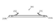
- the tube stent 201 made of a resin material has a distal end 210a and a proximal end 210b and extends in the longitudinal direction.
- the tube 201 has a distal flap 231 formed by making a notch in the outer surface on the distal side, and a proximal flap 232 formed by making a notch in the outer surface on the proximal side.
- a proximal flap 232 formed by making a notch in the outer surface on the proximal side There are (for example, Patent Documents 1 and 2).
- the proximal flap 232 and the distal flap 231 have the function of fixing the tube stent 201 in place in the in vivo lumen.
- the distal flap 231 is located distal to the stenosis (obstruction) of the bile duct and proximal to prevent the tube stent 201 from falling off the duodenum from the bile duct.
- the flap 232 is placed near the papilla of the duodenum outside the bile duct to prevent the tube stent 201 from entering the bile duct.
- the purpose of the tube stent is to perform bile drainage on the narrowed part of the bile duct.
- flaps prevent the tube stent from being displaced from a predetermined position in the bile duct.
- the effect of preventing the displacement due to the flap is not sufficient, and the current situation is that the tube stent is displaced.
- the tube stent disclosed in Patent Document 1 includes a magnetic element and a stopper member on the tube.
- the outer diameter of the stopper member is larger than the outer diameter of the portion from the end of the tube to the end of the stopper member, and the magnetic element and the stopper member protrude from the tube surface, so that it is difficult to deliver to the desired indwelling site. was there.
- the tube stent disclosed in Patent Document 2 has a plurality of grooves formed on the outer surface of the tube body along the longitudinal direction. These grooves ensure the flow of body fluids on the outside of the tube and are stochastically intended to be used longer than conventional ones. However, these grooves are not provided for the purpose of preventing the position of the narrowed portion in the living body from being displaced, and there is a problem that some means is required to prevent the position from being displaced after placement. there were.
- the present invention has been made in view of the above circumstances, and an object thereof is to prevent the tube stent from moving without making the outer diameter of the tube stent indwelling too large, and to prevent the tube stent from moving, and to prevent the tube stent from moving. It is an object of the present invention to provide a tube stent capable of facilitating passage through a lesion.
- the tube stent that was able to solve the above-mentioned problems is made of a resin material, has a distal end and a proximal end, and has a first part, a second part, and a third part in order from the distal end in the longitudinal direction.
- a tube having a portion having a first edge at the proximal end of the first portion and a second edge at the proximal end of the second portion, the thickness of the proximal end of the first portion being second. It is thicker than the wall thickness of the distal end of the part, the wall thickness of the second part is thicker from the distal end side to the proximal end side, and the wall thickness of the distal end of the third part is the thickness of the second part. It is thinner than the wall thickness at the proximal end.
- the tube stent of the present invention preferably has a plurality of second portions in the longitudinal direction. It is preferable that the first edge and the second edge are provided on the entire circumference of the outer surface of the tube.
- the difference between the maximum outer diameter and the minimum outer diameter of the tube is preferably 30% or less.
- the outer diameter of the proximal end of the first part or the outer diameter of the proximal end of the second part is the maximum outer diameter
- the outer diameter of the distal end of the first part or the outer diameter of the distal end of the second part is The minimum outer diameter is preferable.
- the outer diameter of any part of the third part is the maximum outer diameter
- the outer diameter of the distal end of the first part or the outer diameter of the distal end of the second part is the minimum outer diameter. ..
- the wall thickness of the proximal end of the first part is thicker than the wall thickness of the distal end of the second part, and the wall thickness of the second part is from the distal end side to the proximal end side.
- the wall thickness is thicker toward, and the wall thickness at the distal end of the third part is thinner than the wall thickness at the proximal end of the second part, so that the outer diameter of the tube stent placed in the living body is increased. It is possible to impart an edge that is caught in the narrowed portion without being too much. Therefore, it is possible to prevent the tube stent from moving after indwelling and to facilitate passage to a lesion such as a stenosis.
- the tube stent is used by attaching it to a delivery system (transport device) such as a catheter having a site where the tube stent is installed in order to transport the tube stent to the lesion.
- a delivery system transport device
- transport device such as a catheter having a site where the tube stent is installed in order to transport the tube stent to the lesion.
- the proximal end refers to the direction on the hand side of the user (operator) with respect to the extending direction of the tube stent, and the direction opposite to the distal end on the proximal side (that is, the direction toward the treatment target side). ). Further, the direction from the proximal end side to the distal end side of the tube stent is referred to as a longitudinal direction.
- the tube stent 1 of the present invention has a distal end 10a and a proximal end 10b, and the first part 21, the second part 22, and the third part 23 are in order from the distal end 10a. It is a tube having.
- the distal end 10a is the distal end of the delivery system and the proximal end 10b is located proximally. In the living body, the distal end 10a is arranged in the deep part of the body.
- the tube stent 1 is made of a resin material.
- the resin material include polyamide-based resin, polyester-based resin, polyurethane-based resin, polyolefin-based resin, fluororesin, vinyl chloride-based resin, silicone-based resin, and natural rubber. Only one of these may be used, or two or more thereof may be used in combination.
- a polyamide-based resin, a polyurethane-based resin, a polyolefin-based resin, and a fluorine-based resin are preferably used.
- the tube stent 1 has at least one of a polyamide-based resin, a polyurethane-based resin, a polyolefin-based resin, and a fluororesin, the biocompatibility and flexibility of the tube stent 1 can be achieved at the same time.
- the length of the tube stent 1 in the longitudinal direction is not particularly limited, but is preferably 3 cm or more and 18 cm or less. Of the total length of the tube stent 1 in the longitudinal direction, it is preferable that the first part 21 is 10 mm to 20 mm, the second part 22 is 1 mm to 5 mm, and the third part 23 is the rest. Although not shown, flaps may be provided in the first part 21 and the third part 23, and the length of the flaps is preferably 5 mm to 15 mm. A plurality of second parts 22 may be repeatedly provided. It is desirable that the length of the second part 22 is shorter than that of the first part 21 and the third part 23, because if the length is too long, kink is likely to occur.
- the first edge 11 is located at the proximal end of the first part 21, and the second edge 12 is located at the proximal end of the second part 22.
- the first edge 11 is an edge of the first part 21 formed by making the wall thickness of the proximal end of the first part 21 thicker than the wall thickness of the distal end of the second part 22.
- the second edge 12 is an edge of the second part 22 formed by making the wall thickness of the proximal end of the second part 22 thicker than the wall thickness of the distal end of the third part 23.
- the first edge 11 may be formed over the entire outer circumference of the tube stent 1, or may be formed on a part of the outer circumference of the tube stent 1.
- the total thickness of the proximal end of the first part 21 is thicker than the total thickness of the distal end of the second part 22. ..
- the meat at the proximal end of the first part 21 is formed.
- At least a portion of the thickness is thicker than at least a portion of the wall thickness at the distal end of Part 2.22. That is, part or all of the wall thickness at the proximal end of Part 1 21 is thicker than part or all of the wall thickness at the distal end of Part 2.
- the tube stent 1 by providing the tube stent 1 with a plurality of edges such as the first edge 11 and the second edge 12, these edges are effectively caught in the narrowed portion, and the tube stent 1 moves to cause misalignment. Can be prevented. Further, if the edge is caught in the lumen in the living body during the transportation of the tube stent 1, it becomes difficult to transport the tube stent 1 to the target site.
- the first edge 11 and the second edge 12 of the present invention are the tube stent 1. Since the wall thickness of the tube stent 1 is once thinned and then thickened at the edge portion, the first edge 11 and the second edge 12 are less likely to be caught in the lumen of the living body when the tube stent 1 is transported. ing.
- the wall thickness of the second part 22 becomes thicker from the distal end side to the proximal end side.
- the second edge 12 is formed by forming the protrusion into a tapered shape and providing the second edge 12 on the second portion 22, the second edge 12 is caught on the stenosis portion when the tube stent 1 is transported (when the stenosis is breached). It's getting harder.
- the wall thickness at the distal end of the third part 23 is thinner than the wall thickness at the proximal end of the second part 22. As a result, the second edge 12 is formed at the proximal end of the second part 22.
- the present invention by providing a plurality of edges on the main body of the tube stent 1, it is possible to prevent the tube stent 1 from moving with respect to the narrowed portion and shifting its position. If a protrusion or the like is directly applied to the tube stent body in order to prevent the position of the tube stent from being displaced as in the conventional case, the protrusion protrudes from the surface of the tube stent, and the outer diameter of the portion where the protrusion is provided becomes large. Therefore, the conventional tube stent has a problem that it is difficult to deliver to a desired indwelling site.
- the first edge 11 and the second edge 12 are provided so as to prevent the tube stent 1 from moving without increasing the outer diameter of the main body too much.
- Having a plurality of second edges 12 means that a plurality of tapered structures such as the second portion 22 are provided in the longitudinal axis direction. That is, by providing a plurality of the second portions 22, the number of the second edges 12 can be a plurality. Due to the plurality of second edges 12, when the tube stent 1 is placed at an arbitrary position, even if it is a lesion having a plurality of stenosis or a lesion such as a soft and slippery new intima. , The plurality of second edges 12 can prevent the tube stent 1 from moving.
- the first edge 11 and the second edge 12 may be provided on the entire circumference of the outer surface of the tube stent 1. Since the first edge 11 and the second edge 12 are located all around the outer surface of the tube stent 1, the tube stent 1 is located regardless of the position of the lesion in the radial direction of the in vivo lumen. The tube stent 1 can be prevented from moving by the first edge 11 and the second edge 12 present on the entire circumference of the outer surface of the tube.
- the first edge 11 and the second edge 12 may be provided on a part of the outer circumference of the tube stent 1. In this case, a plurality of first edges 11 and second edges 12 may be arranged so as to be arranged on the outer periphery of the tube stent 1 to form streaky first edges 11 and second edges 12 in the longitudinal direction.
- the first edge 11 and the first edge are the first.
- the two edges 12 are likely to be caught in the lesion, and the effect of preventing the tube stent 1 from moving is enhanced. It is desirable that the wall thickness difference between the first edge 11 and the distal end of the second part 22 and the wall thickness difference between the second edge 12 and the distal end of the third part 23 are large.
- the first edge 11 is formed by making the wall thickness of the proximal end of the first part 21 thicker than the wall thickness of the distal end of the second part 22.
- the second edge 12 has a tapered shape, so that when the tube stent 1 is transported (when the stenosis is breached), The second edge 12 is less likely to be caught in the narrowed portion.
- the wall thickness at the distal end of the third part 23 is thinner than the wall thickness at the proximal end of the second part 22 to form the second edge 12, and the distal ends of the second edge 12 and the third part 23.
- the difference between the maximum outer diameter and the minimum outer diameter of the tube stent 1 is 30% or less.
- the difference between the maximum outer diameter and the minimum outer diameter of the tube stent 1 is 30% or less, the difference in the outer diameter between the distal ends of the first edge 11 and the second part 22 and the difference between the second edge 12 and the third part 23
- the difference in outer diameter at the distal end of the tube stent 1 can be increased, and the effect of preventing the tube stent 1 from moving can be enhanced.
- the difference between the maximum outer diameter and the minimum outer diameter of the tube stent 1 is large, but if the outer diameter difference exceeds 30%, it is between the distal end of the first edge 11 and the second part 22, or the second edge.
- Kink is likely to occur between 12 and the distal end of Part 3 23, so 30% or less is desirable.
- the lower limit of the difference between the maximum outer diameter and the minimum outer diameter of the tube stent 1 is preferably 10% or more, more preferably 13% or more, and further preferably 15% or more.
- the outer diameter of the proximal end of the first part 21 or the outer diameter of the proximal end of the second part 22 is the maximum outer diameter, and the outer diameter of the distal end of the first part 21 or the distal end of the second part 22. It is preferable that the outer diameter of is the minimum outer diameter.
- the maximum outer diameter of the tube stent 1 is the outer diameter of the proximal end of the first part 21 or the outer diameter of the proximal end of the second part 22, and the minimum outer diameter of the tube stent 1 is the distal end of the first part 21.
- the outer diameter of the tube stent 1 or the outer diameter of the distal end of the second part 22 can be used to balance the overall rigidity of the tube stent 1.
- the outer diameter of any part of the third part 23 is the maximum outer diameter, and the outer diameter of the distal end of the first part 21 or the outer diameter of the distal end of the second part 22 is the minimum outer diameter. Is preferable.
- the maximum outer diameter of the tube stent 1 is the outer diameter of any part of the third part 23, and the minimum outer diameter of the tube stent 1 is the outer diameter of the distal end of the first part 21 or the distal of the second part 22. Due to the outer diameter of the end, the tube stent 1 having a well-balanced overall rigidity can be obtained.
- the edge of the tube stent 1 of the present invention can be formed by various methods.
- the outer surface of the tube can be tapered or edged by heating the tube and shaping it using a mold.
- the tube stent 1 of the present invention can be formed by connecting short tubes provided with a taper or an edge.
- a taper or edge can be provided by scraping or cutting the outer surface of the tube with a cutting tool. Since it is preferable that the outer surface and the inner surface of the edge portion of the tube stent 1 do not communicate with each other, it is preferable to process the tube stent 1 after passing a core material or the like through the lumen of the tube.
- Tube stent 10a Distal end 10b: Proximal end 11: First edge 12: Second edge 21: Part 1 22: Part 2 23: Part 3 201: Tube stent 210a: Distal end 210b: Proximal end 231: Distal flap 232: Proximal flap
Landscapes
- Health & Medical Sciences (AREA)
- Engineering & Computer Science (AREA)
- Biomedical Technology (AREA)
- Cardiology (AREA)
- Oral & Maxillofacial Surgery (AREA)
- Transplantation (AREA)
- Heart & Thoracic Surgery (AREA)
- Vascular Medicine (AREA)
- Life Sciences & Earth Sciences (AREA)
- Animal Behavior & Ethology (AREA)
- General Health & Medical Sciences (AREA)
- Public Health (AREA)
- Veterinary Medicine (AREA)
- Media Introduction/Drainage Providing Device (AREA)
Priority Applications (1)
| Application Number | Priority Date | Filing Date | Title |
|---|---|---|---|
| JP2022545462A JP7651582B2 (ja) | 2020-08-28 | 2021-06-14 | チューブステント |
Applications Claiming Priority (2)
| Application Number | Priority Date | Filing Date | Title |
|---|---|---|---|
| JP2020-144582 | 2020-08-28 | ||
| JP2020144582 | 2020-08-28 |
Publications (1)
| Publication Number | Publication Date |
|---|---|
| WO2022044488A1 true WO2022044488A1 (ja) | 2022-03-03 |
Family
ID=80353059
Family Applications (1)
| Application Number | Title | Priority Date | Filing Date |
|---|---|---|---|
| PCT/JP2021/022447 Ceased WO2022044488A1 (ja) | 2020-08-28 | 2021-06-14 | チューブステント |
Country Status (2)
| Country | Link |
|---|---|
| JP (1) | JP7651582B2 (https=) |
| WO (1) | WO2022044488A1 (https=) |
Citations (5)
| Publication number | Priority date | Publication date | Assignee | Title |
|---|---|---|---|---|
| JP2000316979A (ja) * | 1999-05-10 | 2000-11-21 | Fuji Systems Kk | ステント |
| US20100100170A1 (en) * | 2008-10-22 | 2010-04-22 | Boston Scientific Scimed, Inc. | Shape memory tubular stent with grooves |
| US20170014247A1 (en) * | 2015-07-15 | 2017-01-19 | Cook Medical Technologies Llc | Stent Anti-Migration Mechanism |
| WO2018230435A1 (ja) * | 2017-06-13 | 2018-12-20 | 株式会社カネカ | 生体内留置チューブ |
| JP2020072872A (ja) * | 2012-04-06 | 2020-05-14 | ボストン サイエンティフィック サイムド,インコーポレイテッドBoston Scientific Scimed,Inc. | 内部人工器官 |
-
2021
- 2021-06-14 JP JP2022545462A patent/JP7651582B2/ja active Active
- 2021-06-14 WO PCT/JP2021/022447 patent/WO2022044488A1/ja not_active Ceased
Patent Citations (5)
| Publication number | Priority date | Publication date | Assignee | Title |
|---|---|---|---|---|
| JP2000316979A (ja) * | 1999-05-10 | 2000-11-21 | Fuji Systems Kk | ステント |
| US20100100170A1 (en) * | 2008-10-22 | 2010-04-22 | Boston Scientific Scimed, Inc. | Shape memory tubular stent with grooves |
| JP2020072872A (ja) * | 2012-04-06 | 2020-05-14 | ボストン サイエンティフィック サイムド,インコーポレイテッドBoston Scientific Scimed,Inc. | 内部人工器官 |
| US20170014247A1 (en) * | 2015-07-15 | 2017-01-19 | Cook Medical Technologies Llc | Stent Anti-Migration Mechanism |
| WO2018230435A1 (ja) * | 2017-06-13 | 2018-12-20 | 株式会社カネカ | 生体内留置チューブ |
Also Published As
| Publication number | Publication date |
|---|---|
| JP7651582B2 (ja) | 2025-03-26 |
| JPWO2022044488A1 (https=) | 2022-03-03 |
Similar Documents
| Publication | Publication Date | Title |
|---|---|---|
| US11766542B2 (en) | Catheter | |
| US20170028170A1 (en) | Guide catheter extension device and methods of use for cardiology procedures | |
| CA2695963A1 (en) | Deployment system for soft stents | |
| WO2018054275A1 (zh) | 一种可扩导管鞘和介入器械输送装置 | |
| EP3811899B1 (en) | Stent for bypass between hollow organs and stent delivery system including stent for bypass between hollow organs | |
| JP2024141523A (ja) | 医療用長尺体 | |
| JP6415541B2 (ja) | ステントデリバリーシステム及び内視鏡システム | |
| JP6125633B2 (ja) | ずれ防止胆管ステント | |
| CN112714659B (zh) | 医疗用管状体运送装置 | |
| JP7410990B2 (ja) | 生体内留置チューブ | |
| JP7378459B2 (ja) | 医療用管状体搬送装置およびその製造方法 | |
| JP7378460B2 (ja) | 医療用管状体搬送装置およびその製造方法 | |
| WO2022044488A1 (ja) | チューブステント | |
| WO2024043219A1 (ja) | ステントキット、ステントキットを有するステントシステム、およびステントキットの製造方法 | |
| JP2011255001A (ja) | カテーテル補助具およびカテーテルユニット | |
| JP6633513B2 (ja) | カテーテル及びカテーテルセット | |
| JP7849983B2 (ja) | 胆管用チューブステント | |
| CN113556992A (zh) | 医疗用管状体输送装置 | |
| JP7329042B2 (ja) | 医療用管状体搬送装置 | |
| WO2022209351A1 (ja) | 医療用管状体搬送装置およびその製造方法 | |
| WO2024172101A1 (ja) | 医療用具 | |
| WO2025074843A1 (ja) | 医療用具 | |
| JP2018201575A (ja) | カテーテルおよびその製造方法 | |
| WO2025150326A1 (ja) | 医療用具 | |
| WO2025177936A1 (ja) | 生体内留置具 |
Legal Events
| Date | Code | Title | Description |
|---|---|---|---|
| 121 | Ep: the epo has been informed by wipo that ep was designated in this application |
Ref document number: 21860919 Country of ref document: EP Kind code of ref document: A1 |
|
| ENP | Entry into the national phase |
Ref document number: 2022545462 Country of ref document: JP Kind code of ref document: A |
|
| NENP | Non-entry into the national phase |
Ref country code: DE |
|
| 122 | Ep: pct application non-entry in european phase |
Ref document number: 21860919 Country of ref document: EP Kind code of ref document: A1 |