WO2022038915A1 - アタッチメントの目標軌跡変更システム - Google Patents
アタッチメントの目標軌跡変更システム Download PDFInfo
- Publication number
- WO2022038915A1 WO2022038915A1 PCT/JP2021/025698 JP2021025698W WO2022038915A1 WO 2022038915 A1 WO2022038915 A1 WO 2022038915A1 JP 2021025698 W JP2021025698 W JP 2021025698W WO 2022038915 A1 WO2022038915 A1 WO 2022038915A1
- Authority
- WO
- WIPO (PCT)
- Prior art keywords
- target
- change
- attachment
- point
- target point
- Prior art date
Links
- 230000036544 posture Effects 0.000 description 59
- 230000000694 effects Effects 0.000 description 26
- 239000004576 sand Substances 0.000 description 9
- 238000004891 communication Methods 0.000 description 7
- 238000010586 diagram Methods 0.000 description 7
- 238000000034 method Methods 0.000 description 5
- 238000009412 basement excavation Methods 0.000 description 4
- 230000001133 acceleration Effects 0.000 description 3
- XEEYBQQBJWHFJM-UHFFFAOYSA-N Iron Chemical compound [Fe] XEEYBQQBJWHFJM-UHFFFAOYSA-N 0.000 description 2
- 230000008602 contraction Effects 0.000 description 2
- 238000001514 detection method Methods 0.000 description 2
- 230000004048 modification Effects 0.000 description 2
- 238000012986 modification Methods 0.000 description 2
- 238000005070 sampling Methods 0.000 description 2
- 230000000007 visual effect Effects 0.000 description 2
- 241000030361 Girellinae Species 0.000 description 1
- 230000003247 decreasing effect Effects 0.000 description 1
- 229910052742 iron Inorganic materials 0.000 description 1
- 230000003252 repetitive effect Effects 0.000 description 1
- 239000002689 soil Substances 0.000 description 1
Images


Classifications
-
- E—FIXED CONSTRUCTIONS
- E02—HYDRAULIC ENGINEERING; FOUNDATIONS; SOIL SHIFTING
- E02F—DREDGING; SOIL-SHIFTING
- E02F9/00—Component parts of dredgers or soil-shifting machines, not restricted to one of the kinds covered by groups E02F3/00 - E02F7/00
- E02F9/26—Indicating devices
- E02F9/264—Sensors and their calibration for indicating the position of the work tool
-
- E—FIXED CONSTRUCTIONS
- E02—HYDRAULIC ENGINEERING; FOUNDATIONS; SOIL SHIFTING
- E02F—DREDGING; SOIL-SHIFTING
- E02F9/00—Component parts of dredgers or soil-shifting machines, not restricted to one of the kinds covered by groups E02F3/00 - E02F7/00
- E02F9/26—Indicating devices
- E02F9/261—Surveying the work-site to be treated
- E02F9/262—Surveying the work-site to be treated with follow-up actions to control the work tool, e.g. controller
-
- E—FIXED CONSTRUCTIONS
- E02—HYDRAULIC ENGINEERING; FOUNDATIONS; SOIL SHIFTING
- E02F—DREDGING; SOIL-SHIFTING
- E02F3/00—Dredgers; Soil-shifting machines
- E02F3/04—Dredgers; Soil-shifting machines mechanically-driven
- E02F3/28—Dredgers; Soil-shifting machines mechanically-driven with digging tools mounted on a dipper- or bucket-arm, i.e. there is either one arm or a pair of arms, e.g. dippers, buckets
- E02F3/36—Component parts
- E02F3/42—Drives for dippers, buckets, dipper-arms or bucket-arms
- E02F3/43—Control of dipper or bucket position; Control of sequence of drive operations
- E02F3/435—Control of dipper or bucket position; Control of sequence of drive operations for dipper-arms, backhoes or the like
- E02F3/437—Control of dipper or bucket position; Control of sequence of drive operations for dipper-arms, backhoes or the like providing automatic sequences of movements, e.g. linear excavation, keeping dipper angle constant
-
- E—FIXED CONSTRUCTIONS
- E02—HYDRAULIC ENGINEERING; FOUNDATIONS; SOIL SHIFTING
- E02F—DREDGING; SOIL-SHIFTING
- E02F3/00—Dredgers; Soil-shifting machines
- E02F3/04—Dredgers; Soil-shifting machines mechanically-driven
- E02F3/28—Dredgers; Soil-shifting machines mechanically-driven with digging tools mounted on a dipper- or bucket-arm, i.e. there is either one arm or a pair of arms, e.g. dippers, buckets
- E02F3/36—Component parts
- E02F3/42—Drives for dippers, buckets, dipper-arms or bucket-arms
- E02F3/43—Control of dipper or bucket position; Control of sequence of drive operations
- E02F3/435—Control of dipper or bucket position; Control of sequence of drive operations for dipper-arms, backhoes or the like
- E02F3/439—Automatic repositioning of the implement, e.g. automatic dumping, auto-return
-
- E—FIXED CONSTRUCTIONS
- E02—HYDRAULIC ENGINEERING; FOUNDATIONS; SOIL SHIFTING
- E02F—DREDGING; SOIL-SHIFTING
- E02F9/00—Component parts of dredgers or soil-shifting machines, not restricted to one of the kinds covered by groups E02F3/00 - E02F7/00
- E02F9/20—Drives; Control devices
- E02F9/2025—Particular purposes of control systems not otherwise provided for
- E02F9/2045—Guiding machines along a predetermined path
-
- E—FIXED CONSTRUCTIONS
- E02—HYDRAULIC ENGINEERING; FOUNDATIONS; SOIL SHIFTING
- E02F—DREDGING; SOIL-SHIFTING
- E02F9/00—Component parts of dredgers or soil-shifting machines, not restricted to one of the kinds covered by groups E02F3/00 - E02F7/00
- E02F9/24—Safety devices, e.g. for preventing overload
-
- E—FIXED CONSTRUCTIONS
- E02—HYDRAULIC ENGINEERING; FOUNDATIONS; SOIL SHIFTING
- E02F—DREDGING; SOIL-SHIFTING
- E02F9/00—Component parts of dredgers or soil-shifting machines, not restricted to one of the kinds covered by groups E02F3/00 - E02F7/00
- E02F9/26—Indicating devices
- E02F9/261—Surveying the work-site to be treated
-
- E—FIXED CONSTRUCTIONS
- E02—HYDRAULIC ENGINEERING; FOUNDATIONS; SOIL SHIFTING
- E02F—DREDGING; SOIL-SHIFTING
- E02F9/00—Component parts of dredgers or soil-shifting machines, not restricted to one of the kinds covered by groups E02F3/00 - E02F7/00
- E02F9/26—Indicating devices
- E02F9/264—Sensors and their calibration for indicating the position of the work tool
- E02F9/265—Sensors and their calibration for indicating the position of the work tool with follow-up actions (e.g. control signals sent to actuate the work tool)
-
- G—PHYSICS
- G06—COMPUTING; CALCULATING OR COUNTING
- G06F—ELECTRIC DIGITAL DATA PROCESSING
- G06F3/00—Input arrangements for transferring data to be processed into a form capable of being handled by the computer; Output arrangements for transferring data from processing unit to output unit, e.g. interface arrangements
- G06F3/01—Input arrangements or combined input and output arrangements for interaction between user and computer
- G06F3/048—Interaction techniques based on graphical user interfaces [GUI]
- G06F3/0484—Interaction techniques based on graphical user interfaces [GUI] for the control of specific functions or operations, e.g. selecting or manipulating an object, an image or a displayed text element, setting a parameter value or selecting a range
- G06F3/04845—Interaction techniques based on graphical user interfaces [GUI] for the control of specific functions or operations, e.g. selecting or manipulating an object, an image or a displayed text element, setting a parameter value or selecting a range for image manipulation, e.g. dragging, rotation, expansion or change of colour
-
- G—PHYSICS
- G06—COMPUTING; CALCULATING OR COUNTING
- G06F—ELECTRIC DIGITAL DATA PROCESSING
- G06F3/00—Input arrangements for transferring data to be processed into a form capable of being handled by the computer; Output arrangements for transferring data from processing unit to output unit, e.g. interface arrangements
- G06F3/01—Input arrangements or combined input and output arrangements for interaction between user and computer
- G06F3/048—Interaction techniques based on graphical user interfaces [GUI]
- G06F3/0484—Interaction techniques based on graphical user interfaces [GUI] for the control of specific functions or operations, e.g. selecting or manipulating an object, an image or a displayed text element, setting a parameter value or selecting a range
- G06F3/04847—Interaction techniques to control parameter settings, e.g. interaction with sliders or dials
-
- E—FIXED CONSTRUCTIONS
- E02—HYDRAULIC ENGINEERING; FOUNDATIONS; SOIL SHIFTING
- E02F—DREDGING; SOIL-SHIFTING
- E02F3/00—Dredgers; Soil-shifting machines
- E02F3/04—Dredgers; Soil-shifting machines mechanically-driven
- E02F3/28—Dredgers; Soil-shifting machines mechanically-driven with digging tools mounted on a dipper- or bucket-arm, i.e. there is either one arm or a pair of arms, e.g. dippers, buckets
- E02F3/30—Dredgers; Soil-shifting machines mechanically-driven with digging tools mounted on a dipper- or bucket-arm, i.e. there is either one arm or a pair of arms, e.g. dippers, buckets with a dipper-arm pivoted on a cantilever beam, i.e. boom
- E02F3/32—Dredgers; Soil-shifting machines mechanically-driven with digging tools mounted on a dipper- or bucket-arm, i.e. there is either one arm or a pair of arms, e.g. dippers, buckets with a dipper-arm pivoted on a cantilever beam, i.e. boom working downwardly and towards the machine, e.g. with backhoes
-
- E—FIXED CONSTRUCTIONS
- E02—HYDRAULIC ENGINEERING; FOUNDATIONS; SOIL SHIFTING
- E02F—DREDGING; SOIL-SHIFTING
- E02F3/00—Dredgers; Soil-shifting machines
- E02F3/04—Dredgers; Soil-shifting machines mechanically-driven
- E02F3/28—Dredgers; Soil-shifting machines mechanically-driven with digging tools mounted on a dipper- or bucket-arm, i.e. there is either one arm or a pair of arms, e.g. dippers, buckets
- E02F3/36—Component parts
- E02F3/42—Drives for dippers, buckets, dipper-arms or bucket-arms
- E02F3/43—Control of dipper or bucket position; Control of sequence of drive operations
- E02F3/435—Control of dipper or bucket position; Control of sequence of drive operations for dipper-arms, backhoes or the like
- E02F3/436—Control of dipper or bucket position; Control of sequence of drive operations for dipper-arms, backhoes or the like for keeping the dipper in the horizontal position, e.g. self-levelling
-
- G—PHYSICS
- G06—COMPUTING; CALCULATING OR COUNTING
- G06F—ELECTRIC DIGITAL DATA PROCESSING
- G06F3/00—Input arrangements for transferring data to be processed into a form capable of being handled by the computer; Output arrangements for transferring data from processing unit to output unit, e.g. interface arrangements
- G06F3/01—Input arrangements or combined input and output arrangements for interaction between user and computer
- G06F3/048—Interaction techniques based on graphical user interfaces [GUI]
- G06F3/0484—Interaction techniques based on graphical user interfaces [GUI] for the control of specific functions or operations, e.g. selecting or manipulating an object, an image or a displayed text element, setting a parameter value or selecting a range
- G06F3/04842—Selection of displayed objects or displayed text elements
-
- G—PHYSICS
- G06—COMPUTING; CALCULATING OR COUNTING
- G06F—ELECTRIC DIGITAL DATA PROCESSING
- G06F3/00—Input arrangements for transferring data to be processed into a form capable of being handled by the computer; Output arrangements for transferring data from processing unit to output unit, e.g. interface arrangements
- G06F3/01—Input arrangements or combined input and output arrangements for interaction between user and computer
- G06F3/048—Interaction techniques based on graphical user interfaces [GUI]
- G06F3/0487—Interaction techniques based on graphical user interfaces [GUI] using specific features provided by the input device, e.g. functions controlled by the rotation of a mouse with dual sensing arrangements, or of the nature of the input device, e.g. tap gestures based on pressure sensed by a digitiser
- G06F3/0488—Interaction techniques based on graphical user interfaces [GUI] using specific features provided by the input device, e.g. functions controlled by the rotation of a mouse with dual sensing arrangements, or of the nature of the input device, e.g. tap gestures based on pressure sensed by a digitiser using a touch-screen or digitiser, e.g. input of commands through traced gestures
Definitions
- the present invention relates to a target trajectory changing system for attachments, which changes the target trajectory of a specific part of the attachment of a work machine.
- Patent Document 1 there is a technique for making the excavator automatically perform a series of repetitive operations based on the excavation position and the soil discharge position taught in advance.
- a specific part of the attachment for example, the tip of the bucket
- a target trajectory for example, depending on the situation at the work site, it may be desired to change a part of the target trajectory. In this case, it is inefficient to reset all the target trajectories by resetting the teaching.
- An object of the present invention is to provide a target trajectory changing system for an attachment, which can improve the work efficiency of the work of changing the target trajectory of a specific part of the attachment.
- the target trajectory changing system of the attachment is used for a work machine having a lower traveling body, an upper turning body rotatably attached to the upper part of the lower traveling body, and an attachment attached to the upper turning body.
- the target locus changing system of the attachment includes a target point setting means, a display device, a target point selection means, a range setting means, a target point moving means, and a target locus resetting means.
- the target point setting means sets a target point at a specific interval on a target locus of a specific portion of the attachment.
- the display device displays the target locus and the target point.
- the target point selection means causes an operator to select any one of the plurality of target points as a change target point.
- the range setting means sets a movable range, which is a range in which the change target point can be moved.
- the target point moving means moves the change target point to the worker within the movable range.
- the target locus resetting means resets the target locus from the change start point to the change end point so that the target locus passes through the change target point after movement, which is the change target point after movement. do.
- the change start point is the target point located in front of the change target point.
- the change end point is the target point located behind the change target point.
- the target locus change system 1 of the attachment 30 changes the target locus 71 (see FIG. 3) of a specific portion of the attachment 30 of the work machine 2 shown in FIG.
- the target trajectory changing system 1 has a work machine 2, a mobile terminal 3, and a camera 4 (surrounding condition acquisition device).
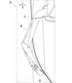
- the work machine 2 is a machine that performs work with the attachment 30, and is, for example, a hydraulic excavator.
- the work machine 2 includes a lower traveling body 21, an upper swivel body 22, a swivel device 24, an attachment 30, a cylinder 40, an operation lever 51 (see FIG. 2), a swivel angle sensor 52, and an inclination angle sensor 60. And have.
- the lower traveling body 21 is a part for traveling the work machine 2, and is provided with, for example, a crawler.
- the upper swivel body 22 is rotatably attached to the upper part of the lower traveling body 21.
- the upper swivel body 22 has a cab 23 (driver's cab) provided at the front portion of the upper swivel body 22.
- the swivel device 24 can swivel the upper swivel body 22 with respect to the lower traveling body 21.
- the attachment 30 is attached to the upper swing body 22 so as to be rotatable in the vertical direction.
- the attachment 30 includes a boom 31, an arm 32, and a bucket 33 (tip attachment).
- the boom 31 is attached to the upper swing body 22 so as to be rotatable in the vertical direction.
- the arm 32 is attached to the boom 31 so as to be rotatable in the vertical direction.
- the bucket 33 is attached to the arm 32 so as to be rotatable in the vertical direction.
- the bucket 33 is a part of a work target (earth and sand, etc.) for excavating, holding, dropping, leveling, scooping, and the like.
- the bucket 33 is an example of a tip attachment attached to the arm 32, and the tip attachment is not limited to this, and may be a nibbler, a clamp arm, or the like. Further, the work target of the bucket 33 may be earth and sand, gravel, rubble, iron scraps, and the like.
- the directions in which the tip of the bucket 33 can be moved are the front-rear direction of the upper swivel body 22 and the vertical direction of the upper swivel body 22.
- the attachment 30 expands and contracts in the front-rear direction of the upper swing body 22. Further, the attachment 30 rotates in the vertical direction of the upper swing body 22.
- the cylinder 40 can rotate the attachment 30 hydraulically.
- the cylinder 40 is a hydraulic telescopic cylinder.
- the cylinder 40 includes a boom cylinder 41, an arm cylinder 42, and a bucket cylinder 43 (tip attachment cylinder).
- the boom cylinder 41 rotationally drives the boom 31 with respect to the upper swing body 22.
- the base end portion of the boom cylinder 41 is rotatably attached to the upper swing body 22.
- the tip of the boom cylinder 41 is rotatably attached to the boom 31.
- the arm cylinder 42 rotates and drives the arm 32 with respect to the boom 31.
- the base end portion of the arm cylinder 42 is rotatably attached to the boom 31.
- the tip of the arm cylinder 42 is rotatably attached to the arm 32.
- the bucket cylinder 43 (tip attachment cylinder) rotationally drives the bucket 33 with respect to the arm 32.
- the base end portion of the bucket cylinder 43 is rotatably attached to the arm 32.
- the tip of the bucket cylinder 43 is rotatably attached to the link member 34 rotatably attached to the bucket 33.
- the operation lever 51 is operated by an operator to operate the swivel device 24 and the attachment 30.
- the operation lever 51 is provided in, for example, the cab 23.
- the operation lever 51 is provided outside the work machine 2.
- the turning angle sensor 52 detects the turning angle ⁇ (see FIG. 12) of the upper turning body 22 with respect to the lower traveling body 21.
- the turning angle sensor 52 is, for example, an encoder, a resolver, a gyro sensor, or the like.
- the turning angle ⁇ of the upper turning body 22 when the front of the upper turning body 22 coincides with the front of the lower traveling body 21 is set to 0 °.
- the tilt angle sensor 60 detects the posture of the attachment 30.
- the tilt angle sensor 60 includes a boom tilt angle sensor 61, an arm tilt angle sensor 62, and a bucket tilt angle sensor 63.
- the boom tilt angle sensor 61 detects the posture of the boom 31.
- the boom tilt angle sensor 61 may be a sensor that acquires the tilt angle of the boom 31 with respect to the horizon, and specifically, for example, a tilt (acceleration) sensor or the like.
- the boom tilt angle sensor 61 is attached to the boom 31.
- the boom tilt angle sensor 61 may be a rotation angle sensor that detects the rotation angle of the boom foot pin (boom base end) or a stroke sensor that detects the stroke amount of the boom cylinder 41.
- the arm tilt angle sensor 62 detects the posture of the arm 32.
- the arm tilt angle sensor 62 may be a sensor that acquires the tilt angle of the arm 32 with respect to the horizon, and specifically, for example, a tilt (acceleration) sensor or the like.
- the arm tilt angle sensor 62 is attached to the arm 32.
- the arm tilt angle sensor 62 may be a rotation angle sensor that detects the rotation angle of the arm connecting pin (arm base end) or a stroke sensor that detects the stroke amount of the arm cylinder 42.
- the bucket tilt angle sensor 63 detects the posture of the bucket 33.
- the bucket tilt angle sensor 63 may be a sensor that acquires the tilt angle of the bucket 33 with respect to the horizon, and specifically, for example, a tilt (acceleration) sensor or the like.
- the bucket tilt angle sensor 63 may be attached to the link member 34 or may be attached to the bucket 33.
- the bucket tilt angle sensor 63 may be a rotation angle sensor that detects the rotation angle of the bucket connecting pin (bucket base end) or a stroke sensor that detects the stroke amount of the bucket cylinder 43.
- the mobile terminal 3 is a terminal operated by a worker (for example, a worker at a work site).
- the mobile terminal 3 may be, for example, a tablet terminal, a smartphone or the like.
- the mobile terminal 3 can communicate with the work machine 2.
- the camera 4 (surrounding condition acquisition device) acquires the surrounding condition 76 (see FIG. 3) of the work machine 2.
- the camera 4 is arranged at a position where the surrounding condition 76 of the attachment 30 can be acquired from the rear of the attachment 30.
- the camera 4 is an example of a surrounding condition acquisition device, and the surrounding condition acquisition device is not limited to this, and may be a lidar (LIDAR; Light Detection and Ranging) or the like. Further, the camera 4 may be installed in the work machine 2 or may be installed in a place away from the work machine 2.
- LIDAR Light Detection and Ranging
- the work machine 2 includes a controller 11, a work machine side communication device 12, and a storage device 13.
- the controller 11 functions as a target point setting means, a target trajectory resetting means, and a specific interval changing means (described later).
- the controller 11 sets the target locus 71 (see FIG. 3) of the specific portion of the attachment 30 (see FIG. 1).
- the specific portion of the attachment 30 shown in FIG. 1 may be, for example, the tip of the bucket 33, the tip of the arm 32, or the like. Hereinafter, a case where the specific portion of the attachment 30 is the tip of the bucket 33 will be mainly described.
- the controller 11 (target point setting means) shown in FIG. 2 sets the target points 72 at specific intervals on the target locus 71 (see FIG. 3).
- the controller 11 sets the target point 72 at each specific interval as information associated with the posture of the attachment 30 (see FIG. 1).
- the posture of the attachment 30 also includes the turning angle ⁇ (see FIG. 12) of the upper turning body 22.
- the specific interval may be a specific time interval (specific time) or a specific distance interval. In this embodiment, the specific interval is a specific time. In this embodiment, the specific time is 1 second.
- the target locus 71 (see FIG. 3) is set by the teaching that actually operates the work machine 2 (see FIG. 1) (online teaching). Specifically, the operator operates the operating lever 51 to operate the swivel device 24 and the attachment 30. The turning angle ⁇ (see FIG. 12) of the upper turning body 22 at this time is detected by the turning angle sensor 52. Further, the posture of the attachment 30 at this time is detected by the tilt angle sensor 60. The controller 11 sets the target locus 71 (see FIG. 3) based on the detected turning angle ⁇ of the upper swing body 22 (see FIG. 1) and the detected posture of the attachment 30.
- the specific interval (more specifically, the specific time) here is the sampling interval (more specifically, the sampling time) of the detection values of the turning angle sensor 52 and the tilt angle sensor 60.
- the target locus 71 (see FIG. 12) by inputting the information on the turning angle ⁇ (see FIG. 12) of the upper turning body 22 and the information on the posture of the attachment 30 to the controller 11 without actually operating the work machine 2. (See FIG. 3) may be set (offline teaching). In this case, for example, the target locus 71 (see FIG. 3) is set by inputting information for each specific interval to the controller 11.
- the controller 11 generates an automatic operation command based on the target locus 71 (see FIG. 4) and the target point 72 (see FIG. 4).
- the automatic operation command is a command for automatically operating the turning device 24 and the attachment 30. Then, the controller 11 can automatically operate the turning device 24 and the attachment 30 based on the automatic operation command.
- the work machine 2 will be automatically operated based on the automatic operation command.
- the work machine side communication device 12 can communicate with the mobile terminal 3 (more specifically, the mobile terminal side communication device 16 described later).
- the storage device 13 can store the target locus 71 (see FIG. 4) and the target point 72 (see FIG. 4) set by the controller 11.
- the mobile terminal 3 has a mobile terminal side controller 15, a mobile terminal side communication device 16, a mobile terminal side storage device 17, a touch panel 18, a display device 19, and a warning device 20.
- the mobile terminal side controller 15 has a target point selection means, a range setting means, a target point moving means, a change start point selection means, a change end point selection means, a first target point moving means, a second target point moving means, and a target attachment selection. It functions as a means and a means for changing the target posture (described later).
- the mobile terminal side communication device 16 can communicate with the work machine side communication device 12 of the work machine 2.
- the mobile terminal side controller 15 receives the target locus 71 (see FIG. 4) and the target point 72 (see FIG. 4) from the work machine 2 via the mobile terminal side communication device 16.
- FIG. 3 which is a diagram showing the display screen of the display device 19
- the display device 19 displays the target locus 71 and the target point 72 (see FIG. 4).
- the display device 19 is, for example, a display of a mobile terminal 3. Note that FIG. 3 does not show the target point 72 (see FIG. 4).
- the display device 19 superimposes and displays the surrounding situation 76 acquired by the camera 4 (see FIG. 1) on the target locus 71 and the target point 72 (see FIG. 4).
- the target locus 71 shown in FIG. 3 is for a lift turn, but is not limited to this, and may be a return turn or the like.
- the lifting swivel is an operation in which the upper swivel body 22 swivels while the work target (earth and sand or the like) scooped by the bucket 33 is held by the bucket 33.
- the return turning is an operation in which the upper swivel body 22 swivels after the work target (earth and sand or the like) held in the bucket 33 is discharged from the bucket 33, and the bucket 33 returns to the excavation position.
- the mobile terminal side storage device 17 can store the target locus 71 (see FIG. 4) and the target point 72 (see FIG. 4) received from the work machine 2.
- the touch panel 18 receives input from an operator.
- the touch panel 18 is an example of an input device, and the input device is not limited to this, and may be, for example, a keyboard or the like.
- the warning device 20 outputs (generates) a warning when the distance between the obstacle included in the surrounding situation 76 shown in FIG. 3 and the target locus 71 is equal to or less than a predetermined value. For example, when the surrounding condition 76 is updated, the warning device 20 outputs a warning when the distance between the newly appearing obstacle and the target locus 71 is equal to or less than a predetermined value.
- the warning device 20 may be a speaker that outputs a warning by voice, a vibrating vibrator, or a device that gives a warning by the display of the display device 19.
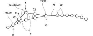
- FIG. 4 shows the target locus 71 and the target point 72 displayed on the display device 19.
- the operator may want to change a part of the target locus 71.
- the worker may want to change a part of the target locus 71 to one suitable for the work site for reasons such as avoiding obstacles.
- the change mode is activated on the mobile terminal 3 (see FIG. 2).
- the mobile terminal side controller 15 target point selection means
- the mobile terminal side controller 15 causes the operator to select one of the plurality of target points 72 as the change target point 73.
- the warning from the warning device 20 prompts the operator to move the target point 72 that is likely to come into contact with an obstacle.
- the operator operates the touch panel 18 (see FIG. 2) to select the change target point 73. Specifically, the operator touches the portion of the touch panel 18 on which the target point 72 to be changed as the target point 73 is displayed. In FIG. 4, the target point 72 indicated by the arrow A is selected as the change target point 73.
- the mobile terminal side controller 15 (change start point selection means) (see FIG. 2) causes the operator to select one of the plurality of target points 72 located in front of the change target point 73 as the change start point 74. ..
- the operator operates the touch panel 18 (see FIG. 2) to select the change start point 74. More specifically, the selection of the change start point 74 is performed by touching the portion of the touch panel 18 superimposed on the desired target point 72 displayed on the display device 19. In FIG. 4, the target point 72 immediately adjacent to the change target point 73 indicated by the arrow B is selected as the change start point 74.
- the mobile terminal side controller 15 (change end point selection means) (see FIG. 2) causes the operator to select one of the plurality of target points 72 located behind the change target point 73 as the change end point 75. ..
- the operator operates the touch panel 18 (see FIG. 2) to select the change end point 75. More specifically, the selection of the change end point 75 is performed by touching the portion of the touch panel 18 superimposed on the desired target point 72 displayed on the display device 19.
- the target point 72 immediately adjacent to the change target point 73 indicated by the arrow C is selected as the change end point 75.
- the mobile terminal side controller 15 sets the movable range of the change target point 73 as the movable range E.
- the movable range E is set based on the posture information of the attachment 30 (see FIG. 2) at at least one of the change target point 73, the change start point 74, and the change end point 75.
- the posture information of the attachment 30 "at the change start point 74" is the posture information of the attachment 30 when it is assumed that the specific portion of the attachment 30 is arranged at the change start point 74 (change target point 73 and the change target point 73 and).
- the movable range E may be set based on the direction with respect to the upper swing body 22 (see the third embodiment).
- a case where the movable range E is set based on the posture information of the attachment 30 at at least one of the change target point 73, the change start point 74, and the change end point 75 will be described.
- the target points 72 are located in front of and behind the change target point 73 indicated by the arrow A, respectively.
- the movable range E is set based on the posture information of the attachment 30 at both the change start point 74 and the change end point 75.
- the change target point 73 is a target point 72 located at either end of the target locus 71
- the target point 72 is located only in front of or behind the target point 72.
- the movable range E is set based on the posture information of the attachment 30 (see FIG. 2) at either the change start point 74 or the change end point 75.
- the movable range E is set based on the posture that the attachment 30 can take (more specifically, the posture that can be physically taken) when it is assumed that the specific portion of the attachment 30 is arranged at the change target point 73. May be good.
- a specific example of the movable range E when the movable range E is set based on the posture information of the attachment 30 is as follows. As described above, in the present embodiment, the specific time is 1 second. Therefore, the posture of the attachment 30 (see FIG. 2) changes from the posture of the change start point 74 to the posture of the change target point 73 after movement in 1 second, and then changes from the posture of the change target point 73 after movement. It is necessary to change to the posture of the end point 75 in 1 second. Under such restrictions, the range in which the change target point 73 can be moved is the movable range E. Specifically, the movable range E includes the expansion / contraction speed of the rod of the cylinder 40 (see FIG. 1), the turning speed of the upper swing body 22 (see FIG.
- the mobile terminal side controller 15 (target point moving means) (see FIG. 2) moves the change target point 73 to the operator within the movable range E. Specific examples of this movement are as follows.
- the display device 19 displays an image including the target locus 71 and the target point 72 as shown in FIG.
- the operator may select the change target point 73 from the target point 72 and move the change target point 73 by performing an operation such as the touch panel 18 (see FIG. 2) (see FIG. 5). ).
- the change target point 73 may be moved from within the movable range E to outside the movable range E by the operation of the operator. In this case, it is preferable to make the operator intuitively recognize that the change target point 73 is about to be moved from the movable range E to the outside of the movable range E.
- the mobile terminal side controller 15 changes the display mode of the image of the display device 19 (see FIG. 2).
- the display device 19 may display characters, figures, and the like.
- the display device 19 may change the display mode of the target locus 71 and the change target point 73.
- the display device 19 may display the change target point 73 semi-transparently, change the color of the change target point 73, or change the display mode of the target locus 71.
- the display device 19 displays an image including the attachment 30 (see FIG. 1) and the target locus 71.
- the operator moves the image of the attachment 30 (see FIG. 1) by performing an operation.
- the change target point 73 may be changed as the image moves.
- the details of the specific example 2 are as follows, for example.
- the mobile terminal side controller 15 causes the operator to select at least one of the boom 31, arm 32, and bucket 33 shown in FIG. 1 as the target attachment.
- the operator operates the touch panel 18 (see FIG. 2) to select the target attachment.
- the bucket 33 holding the work target (earth and sand or the like) is rotated in the vertical direction, the work target may spill. Therefore, in FIG. 3, the arm image 78 corresponding to the arm 32 (see FIG. 1) is selected, so that the arm 32 is selected as the target attachment.
- the boom 31 corresponds to the boom image 77
- the bucket 33 corresponds to the bucket image 79 (tip attachment image).
- the display device 19 When at least one of the boom 31, arm 32, and bucket 33 shown in FIG. 1 is selected as the target attachment, information about the selected target attachment is displayed on the display device 19 shown in FIG. For example, a case where the arm 32 is selected as the target attachment will be described. On the display screen of the display device 19, a character image 81 indicating that the target attachment is the arm 32 is displayed. A numerical image 82 showing a numerical value of the currently set arm angle is displayed on the display device 19. In FIG. 3, the numerical value of the arm angle is "100". Further, the display device 19 displays an increase button image 83 for increasing the numerical value of the arm angle and a decrease button image 84 for decreasing the numerical value of the arm angle.
- the mobile terminal side controller 15 moves the change target point 73 shown in FIG. 4 by causing the worker to change the target posture of the target attachment. More specifically, the controller 15 on the mobile terminal side causes the worker to change the target posture of the target attachment (function as a target posture changing means), and moves the change target point 73 based on the change of the target posture (target point movement). Function as a means). Specifically, for example, the operator touches the increase button image 83 or the decrease button image 84 shown in FIG. 3 to change the numerical value of the arm angle. As a result of changing the target posture of the target attachment, the change target point 73 shown in FIG. 4 moves.
- the position of the specific part of the attachment 30 may be moved from the movable range E to the outside of the movable range E.
- the mobile terminal side controller 15 may change the display mode of the attachment 30, the display mode of the target attachment may be changed, or the display mode of the change target point 73 may be changed.
- the display mode of the target locus 71 may be changed.
- the mobile terminal side controller 15 may change the display of the target attachment semi-transparently.
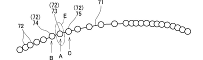
- FIG. 5 shows the target locus 71 and the target point 72 displayed on the display device 19 (see FIG. 3) after the change target point 73 has been moved.
- a part of the target locus 71 is reset (changed).
- the controller 11 of the work machine 2 receives the change target point 73, the change start point 74, and the change end point 75 after the movement from the mobile terminal 3.
- the controller 11 (target locus resetting means) resets the target locus 71 between the change start point 74 and the change end point 75 so that the target locus 71 passes through the change target point 73 after movement (re-setting). See the set target trajectory 71a).
- the target locus 71 and the target point 72 displayed on the display device 19 are shown in FIG.
- a plurality of (for example, two) target points 72 before the change target point 73 are selected as the change start points 74, and a plurality of (for example, two) target points 72 after the change target point 73 are changed.
- it is selected as the end point 75.
- the target point 72 near the front or rear of the change target point 73 is selected as the change start point 74 or the change end point 75 (Case A)
- the target point 72 far from the change target point 73 forward or backward is the change start point.
- case B the time required to move from the change start point 74 to the change end point 75 via the change target point 73 is longer than in case A. The longer this time is, the wider the movable range E of the change target point 73 becomes. Therefore, as the target point 72 selected as the change start point 74 or the change end point 75 is farther forward or backward from the change target point 73, the movable range E of the change target point 73 can be widened.
- FIG. 8 is a flowchart of the target trajectory changing process. In the following, steps S1 to S13 of the flowchart will be described with reference to FIG.
- the mobile terminal side controller 15 of the mobile terminal 3 shown in FIG. 2 activates the change mode (step S1).
- the target locus 71 (see FIG. 4) and the target point 72 (see FIG. 4) received from the work machine 2 are stored in the mobile terminal side storage device 17 of the mobile terminal 3.
- the mobile terminal side controller 15 causes the display device 19 to display the target locus 71 and the target point 72 (step S2).
- the surrounding situation 76 is superimposed and displayed on the display device 19.
- the mobile terminal side controller 15 shown in FIG. 2 determines whether or not the distance between the obstacle included in the surrounding situation 76 (see FIG. 3) and the target locus 71 (see FIG. 3) is equal to or less than a predetermined value. (Step S3).
- step S3 When the mobile terminal side controller 15 determines in step S3 that the distance between the obstacle included in the surrounding condition 76 (see FIG. 3) and the target locus 71 (see FIG. 3) is equal to or less than a predetermined value (S3). : YES), a warning is generated from the warning device 20 (step S4). Then, the mobile terminal side controller 15 proceeds to step S5. On the other hand, when the mobile terminal side controller 15 determines in step S3 that the distance between the obstacle included in the surrounding condition 76 (see FIG. 3) and the target locus 71 (see FIG. 3) is not equal to or less than a predetermined value (see FIG. 3). S3: NO), the process proceeds to step S5.
- step S5 the mobile terminal side controller 15 causes the operator to select the change target point 73 (see FIG. 4) (step S5).
- step S6 the mobile terminal side controller 15 causes the operator to select the change start point 74 (see FIG. 4) and the change end point 75 (see FIG. 4) (step S6).
- the mobile terminal side controller 15 sets the movable range E (step S7). Next, the mobile terminal side controller 15 causes the operator to select the target attachment (step S8). Then, the mobile terminal side controller 15 causes the worker to change the target posture of the target attachment (step S9).
- the mobile terminal side controller 15 determines whether or not the target posture of the changed target attachment is within the movable range E (see FIG. 4) (step S10).
- the mobile terminal side controller 15 determines in step S10 that the target posture of the changed target attachment is not within the movable range E (S10: NO)
- the mobile terminal side controller 15 returns to step S8 (may return to step S9).
- the worker will further change the target posture of the target attachment so that the changed target posture of the target attachment is within the movable range E.
- the target posture of the target attachment is changed to be within the movable range E after being changed to the outside of the movable range E, but the target posture of the target attachment is within the movable range E. Only may be changeable.
- step S10 determines in step S10 that the target posture of the changed target attachment is within the movable range E (see FIG. 4) (S10: YES)
- the process proceeds to step S11. ..
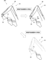
- the mobile terminal side controller 15 causes the display device 19 to display a moving image in which the attachment 30 moves while the tip of the bucket 33 is positioned on the target locus 71 (step S11).
- step S12 determines whether or not the operator has instructed the end of the change of the target locus 71 (see FIG. 3) (step S12). If it is determined in step S12 that the operator has not instructed the end of the change, the mobile terminal side controller 15 returns to step S8 (S12: NO). On the other hand, when the mobile terminal side controller 15 determines in step S12 that the operator has instructed the end of the change (S12: YES), the change content is saved in the mobile terminal side storage device 17 (step S13). , End this flow.
- the effects of the target trajectory changing system 1 of the attachment 30 shown in FIG. 1 are as follows.
- the target trajectory changing system 1 is used for the work machine 2.
- the work machine 2 has a lower traveling body 21, an upper swivel body 22, and an attachment 30.
- the upper swivel body 22 is rotatably attached to the upper part of the lower traveling body 21.
- the attachment 30 is attached to the upper swing body 22.
- the target locus changing system 1 includes a target point setting means, a display device 19 shown in FIG. 3, a target point selection means, a range setting means, a target point moving means, and a target locus resetting means.
- the target point setting means (for example, the controller 11 (see FIG. 2)) sets the target points 72 (see FIG. 4) at specific intervals on the target locus 71 of the specific portion of the attachment 30 (see FIG. 1).
- the display device 19 displays the target locus 71 and the target point 72 (see FIG. 4).
- the target point selection means (for example, the mobile terminal side controller 15 (see FIG. 2)) causes the operator to select one of the plurality of target points 72 shown in FIG. 4 as the change target point 73.
- the range setting means (for example, the controller 15 on the mobile terminal side) sets the movable range E, which is the range in which the change target point 73 can be moved.
- the target point moving means (for example, the mobile terminal side controller 15) moves the change target point 73 to the operator within the movable range E.
- the target locus resetting means (for example, the controller 15 on the mobile terminal side) has a target locus between the change start point 74 and the change end point 75 so that the target locus 71 passes through the post-movement change target point 73a shown in FIG. Reset 71 (see the reset target trajectory 71a).
- the change target point 73a after movement is the change target point 73 after movement.
- the change start point 74 is a target point 72 located in front of the change target point 73.
- the change end point 75 is a target point 72 located behind the change target point 73.
- the above [Structure 1] has the following effects.
- the worker wants to change a part of the target locus 71 at the tip of the bucket 33 (see FIG. 1) (for example, when he / she wants to change the target locus 71 to suit the work site)
- the worker may perform a plurality of work as shown in FIG.
- One of the target points 72 is selected as the change target point 73.
- the worker moves the change target point 73 within the movable range E.
- the target locus 71 is reset (changed) so as to pass through the change target point 73a after the movement (see the reset target locus 71a). ..
- the target point setting means (for example, the controller 11 (see FIG. 2)) sets the target point 72 shown in FIG. 4 as information associated with the posture of the attachment 30 (see FIG. 1).
- the range setting means (for example, the controller 15 on the mobile terminal side (see FIG. 2)) is based on the information on the posture of the attachment 30 at at least one of the change start point 74, the change end point 75, and the change target point 73. Set the movable range E.
- the movable range of the change target point 73 is based on the posture information of the attachment 30 (see FIG. 1) at at least one of the change start point 74, the change end point 75, and the change target point 73. E is set. Therefore, the movable range E can be appropriately limited as compared with the case where the change target point 73 can be moved (for example, to an arbitrary position) without being based on the posture information of the attachment 30. Specifically, for example, the position of the change target point 73 that causes the attachment 30 to have a posture that cannot be physically taken may be set so as not to be included in the movable range E. For example, by appropriately limiting the movable range E, the sudden movement of the attachment 30 may be suppressed.
- the target trajectory changing system 1 has a change start point selection means and a change end point selection means.
- the change start point selection means (for example, the mobile terminal side controller 15 (see FIG. 2)) informs the operator that any of the plurality of target points 72 located in front of the change target point 73 shown in FIG. 7 is set as the change start point 74. Let me choose.
- the change end point selection means (for example, the mobile terminal side controller 15) causes the operator to select one of the plurality of target points 72 located behind the change target point 73 as the change end point 75.
- the operator can arbitrarily select the change start point 74 and the change end point 75. Therefore, the range of the reset target locus 71 (see the reset target locus 71a) can be easily changed.
- the movable range E is set based on the posture information of the attachment 30 at at least one of the change start point 74, the change end point 75, and the change target point 73.
- the movable range E is set based on the posture that the attachment 30 can take when the specific portion of the attachment 30 is arranged at the change target point 73.
- the target point 72 near the front or the rear of the change target point 73 is selected as the change start point 74 or the change end point 75 (case A), the target point 72 far from the change target point 73 forward or backward.
- the target trajectory changing system 1 has a first target point moving means and a second target point moving means.
- the first target point moving means (for example, the mobile terminal side controller 15 (see FIG. 2)) performs the following processing when the target point 72 is between the change start point 74 and the post-movement change target point 73a.
- the first target point moving means shifts the target point 72 between the change start point 74 and the post-movement change target point 73a on the line connecting the change start point 74 and the post-movement change target point 73a.
- the second target point moving means (for example, the mobile terminal side controller 15) performs the following processing when the target point 72 is between the change end point 75 and the post-movement change target point 73a.
- the second target point moving means shifts the target point 72 between the change end point 75 and the post-movement change target point 73a on the line connecting the change end point 75 and the post-movement change target point 73a.
- the target point 72 is on the line connecting the change start point 74 and the change target point 73 after movement. Be staggered. The same applies when the target point 72 is located between the change target point 73 and the change end point 75. As a result, it is possible to save the worker the trouble of moving the target point 72 between the change target point 73 and the change start point 74 and the target point 72 between the change target point 73 and the change end point 75. ..
- the attachment 30 has a boom 31, an arm 32, and a bucket 33 (tip attachment).
- the boom 31 is attached to the upper swing body 22 so as to be rotatable in the vertical direction.
- the arm 32 is attached to the boom 31 so as to be rotatable in the vertical direction.
- the bucket 33 is rotatably attached to the arm 32.
- the target point moving means (for example, the mobile terminal side controller 15 (see FIG. 2)) has a target attachment selection means and a target posture changing means.
- the target attachment selection means (for example, the mobile terminal side controller 15) causes the operator to select at least one of the boom 31, the arm 32, and the bucket 33 as the target attachment.
- the target posture changing means (for example, the controller 15 on the mobile terminal side) moves the change target point 73 (see FIG. 4) by causing the operator to change the target posture of the target attachment.
- At least one of the boom 31, arm 32, and bucket 33 shown in FIG. 1 is selected by the operator as the target attachment (see FIG. 3). Then, the change target point 73 (see FIG. 5) moves by changing the target posture of the target attachment by the worker. In this way, the change target point 73 can be moved by changing the target posture of the target attachment desired by the operator.
- the target trajectory changing system 1 has a camera 4 (surrounding condition acquisition device) that acquires the surrounding condition 76 (see FIG. 3) of the work machine 2.
- the display device 19 superimposes and displays the surrounding situation 76 acquired by the camera 4 (see FIG. 1) on the target locus 71 and the target point 72 (see FIG. 4).
- the operator can easily grasp the relative position between the target locus 71 and the surrounding situation 76 from the display in which the target locus 71 and the surrounding situation 76 are superimposed as shown in FIG. As a result, the operator can easily find, for example, the target point 72 (see FIG. 4) where the attachment 30 is likely to come into contact with the obstacle.
- the target trajectory changing system 1 has a warning device 20.
- the warning device 20 outputs a warning when the distance between the obstacle included in the surrounding situation 76 shown in FIG. 3 and the target locus 71 is equal to or less than a predetermined value.
- the display device 19 displays a moving image in which the attachment 30 moves while the specific portion is positioned on the target locus 71.
- the operator can confirm the movement of the attachment 30 moving along the changed target locus 71 with a moving image. can. As a result, the operator can confirm how the movement result of the change target point 73 (see FIG. 4) affects the movement of the attachment 30.
- the target trajectory changing system 1 has a mobile terminal 3 capable of communicating with the work machine 2.
- the mobile terminal 3 has a display device 19, a target point selection means (see the above [configuration 1]), and a target point moving means (see the above [configuration 1]).
- the target locus 71 and the target point 72 shown in FIG. 4 are displayed on the mobile terminal 3.
- the target locus 71 at the tip of the bucket 33 (see FIG. 1) can be confirmed on the mobile terminal 3 (see FIG. 1) located away from the work machine 2 (see FIG. 1).
- the operator operates the mobile terminal 3 to select the change target point 73, and moves the change target point 73 within the movable range E.
- a part of the target locus 71 can be changed on the mobile terminal 3 located at a place away from the work machine 2, for example.
- the target trajectory changing system 201 of the second embodiment will be described with reference to the drawings.
- the common points with the first embodiment common configuration and effects produced by the common configuration
- the points different from the first embodiment will be mainly described (third embodiment to be described later).
- the same members of the target trajectory changing system 201 of the second embodiment the same members as those of the first embodiment are designated by the same reference numerals as those of the first embodiment (the same applies to the third embodiment described later).
- FIG. 9 is a diagram showing a display screen of the display device 19 of the mobile terminal 3 (see FIG. 2)
- the display device 19 is the tip of the bucket 33 (attachment 30).
- the image in which the specific part) is located at the change target point 73 is displayed.
- the display device 19 displays so that the position of the tip of the bucket 33 in the image moves according to the operation of the operator on the touch panel 18 (see FIG. 2).
- this display is a display when the movement of the change target point 73 by the operator's operation is within the movable range E.
- the mobile terminal side controller 15 (see FIG. 2) of the mobile terminal 3 (see FIG. 2) moves the change target point 73 according to the position of the tip of the moved bucket 33. As a result, the operator can intuitively move the change target point 73 based on the visual change of the image.
- the display device 19 changes the display mode of the image when the position of the tip of the bucket 33 in the image moves from within the movable range E to outside the movable range E.
- the image of the attachment 30 may be displayed in a semi-transparent manner, and the line indicating the attachment 30 may be changed (for example, the line may be thinned). It may be displayed (for example, by changing from a solid line to a broken line).
- the controller 11 (specific interval changing means) (see FIG. 2) of the work machine 2 (see FIG. 2) causes the operator to change the specific interval (for example, a specific time).
- the mobile terminal side controller 15 may allow the operator to change the specific interval.
- the change of the specific interval may be performed by, for example, an input device and a monitor (not shown) included in the work machine 2, or may be performed by the touch panel 18 and the display device 19 of the mobile terminal 3 (see FIG. 2). ..
- FIG. 10 shows a target locus 71 and a target point 72 displayed on the display device 19. A specific example will be described when the specific interval is a specific time. As shown in FIG.
- the specific time when the specific time is changed from 1 second to 0.5 seconds, the number of target points 72 in a fixed time is doubled (see FIGS. 4 and 10). In this way, if the specific time is shortened, the number of target points 72 in a certain time increases, so that the target locus 71 can be finely (detailed) changed.
- FIG. 11 shows a target locus 71 and a target point 72 displayed on the display device 19.
- the specific time is changed from 1 second to 2 seconds, the number of target points 72 in a fixed time is halved (see FIGS. 4 and 11).
- the specific time is lengthened, the time to move from the change start point 74 to the change end point 75 via the change target point 73 becomes longer.
- the longer this time is, the wider the movable range E of the change target point 73 becomes. Therefore, by lengthening the specific time, the movable range E of the change target point 73 can be widened.
- the specific interval is a distance
- the target trajectory 71 can be finely set by setting the specific interval short. Further, by setting a long specific interval, the movable range E can be widened.
- the target trajectory changing system 201 shown in FIG. 2 has a specific interval changing means (for example, a mobile terminal side controller 15) that causes an operator to change a specific interval.
- a specific interval changing means for example, a mobile terminal side controller 15
- the specific interval is changed by the operator. As shown in FIG. 10, if the specific interval is shortened, the number of target points 72 at a certain time or a certain distance increases (see FIGS. 4 and 10), so that the target locus 71 can be finely changed. Further, if the specific interval is lengthened, as shown in FIG. 11, it takes a long time to move from the change start point 74 to the change end point 75 via the change target point 73. The longer this time is, the wider the movable range E of the change target point 73 becomes. Therefore, by lengthening the specific interval, the movable range E of the change target point 73 can be widened.
- the display device 19 displays an image in which the tip end (specific portion) of the bucket 33 of the attachment 30 is located at the change target point 73.
- the display device 19 displays the position of the tip end (specific portion) of the bucket 33 in the image so as to move according to the operation of the operator.
- the target point moving means (for example, the mobile terminal side controller 15 (see FIG. 2)) moves the change target point 73 according to the position of the tip of the moved bucket 33 in the image.
- the operator can intuitively move the change target point 73 based on the visual change of the image.
- the display device 19 changes the display mode of the image when the position of the tip (specific portion) of the bucket 33 in the image moves from within the movable range E (see FIG. 4) to outside the movable range E. Let me.
- the operator can intuitively recognize that the position of the tip of the bucket 33 in the image has moved from the movable range E (see FIG. 4) to the outside of the movable range E.
- the difference between the target trajectory changing system 301 of the third embodiment and the target trajectory changing system 301 of the first embodiment will be mainly described.
- the main differences are as follows.
- the movable range E shown in FIG. 4 is set based on the posture of the attachment 30 shown in FIG.
- the movable range E shown in FIG. 12 is set based on the direction with respect to the upper swivel body 22.
- the movable range E is a range extending in the front-rear direction (X direction) of the upper swivel body 22 and a range extending in the vertical direction (Z direction) of the upper swivel body 22 as shown in FIG. At least one.
- the movable range E does not extend in the direction of the turning angle ⁇ . The details of the differences are as follows.
- the target trajectory changing system 301 has a dump truck D shown in FIG.
- the dump truck D has a truck cab Da and a loading platform Db.
- a work target (earth and sand, etc.) held by the work machine 2 is dropped on the loading platform Db of the dump truck D.
- the controller 11 (target locus setting means) (see FIG. 2) sets the target locus 71 between the target start point 71s and the target end point 71e.
- the target start point 71s is the target point 72 at which the attachment 30 starts to operate.
- the target end point 71e is a target point 72 at which the attachment 30 ends its operation.
- the target start point 71s and the target end point 71e are illustrated by black circles ( ⁇ ), and the other target points 72 are illustrated by white circles ( ⁇ ).
- the target locus 71 shown in FIG. 12 is for a return turn, but the target locus 71 is not limited to this and may be for a lift turn.
- the return turning is an operation in which the upper turning body 22 turns after the work target held by the bucket 33 is discharged, and the bucket 33 is returned to, for example, an excavation point.
- the lifting and turning is an operation in which the upper turning body 22 turns while the bucket 33 holds the work target (for example, the work target scooped at the excavation point).
- the work target is earth and sand
- the target point 72 farthest from the earth and sand mountain 100 is the target start point 71s for starting the return turning operation, and the target point 72 closest to the earth and sand mountain 100 is.
- a dump truck D (see FIG. 1) (see FIG. 1), which is not shown in FIG. 12, is located on the right side of the work machine 2 in FIG. 12 (the same applies to FIGS. 13 and 14).
- FIG. 12 the target locus 71 when the work machine 2 is viewed from the side and the target locus 71 when the work machine 2 is viewed from above are shown in two dimensions, respectively.
- the display device 19 displays the target locus 71 and the target point 72 in two dimensions.
- the display form of the display device 19 is as shown in FIG.
- the mobile terminal side controller 15 causes the operator to select one of the plurality of target points 72 as the change target point 73. Then, the mobile terminal side controller 15 (target point moving means) moves the change target point 73 to at least one of the front-rear direction of the upper swivel body 22 and the vertical direction of the upper swivel body 22 by the operation of the operator (FIG. FIG. 12 and FIG. 14). More specifically, in the present embodiment, the mobile terminal side controller 15 (range setting means) can move the change target point 73 to at least one of the front-rear direction of the upper swivel body 22 and the vertical direction of the upper swivel body 22. Set the movable range E to.
- the movable range E may be a range extending in the front-rear direction of the upper swivel body 22 from the change target point 73 before the movement.
- the movable range E may be a range extending in the vertical direction of the upper swivel body 22 from the change target point 73 before the movement (see FIG. 14).
- the mobile terminal side controller 15 sets the movable range E so that the change target point 73 cannot be moved in a direction other than the front-back direction and the up-down direction of the upper swing body 22 (see FIGS. 12 and 14). ..
- the origin is the turning center of the upper turning body 22, and the three-dimensional coordinates of the change target point 73 are (Xn, Zn, ⁇ n).
- Xn is the distance in the X direction from the origin to the change target point 73.
- the X direction is the front-rear direction of the upper swivel body 22 when it is assumed that the tip of the bucket 33 is arranged at the change target point 73 (not shown).
- Zn is the distance in the Z direction from the bottom surface (for example, the ground) of the lower traveling body 21 to the change target point 73.
- the Z direction is the vertical direction of the upper swivel body 22. When the work machine 2 is arranged on a horizontal plane, the Z direction is the vertical direction.
- ⁇ n is an angle in the ⁇ direction from the front surface of the upper swing body 22 to the axis in the X direction.
- the movable range E is a range extending in the X direction from the change target point 73 before the movement.
- the display device 19 (see FIG. 2) displays as shown in FIG. At this time, the display device 19 displays a two-dimensional image when the work machine 2 is viewed from above, as shown in the lower portion of FIG. In this display, the operator operates (for example, traces) the touch panel 18 (see FIG. 2) to move the change target point 73 in the X direction.
- FIG. 12 shows the change target point 73 after movement (change target point 73a after movement) as a white triangle ( ⁇ ).
- the mobile terminal side controller 15 may set the movable range E based on the posture information of the attachment 30 when it is assumed that the tip of the bucket 33 is arranged at the change target point 73 (see FIG. 2). See first embodiment).
- the size (length) of the movable range E in the X direction may be set based on the posture information of the attachment 30 assuming that the tip of the bucket 33 is arranged at the change target point 73.
- the mobile terminal side controller 15 limits the range in which the change target point 73 can be moved by the operator's operation within the movable range E.
- the mobile terminal side controller 15 causes the operator to select one of the plurality of target points 72 as the change start point 74 and the change end point 75 (similar to the first embodiment).
- the target start point 71s is selected as the change start point 74.
- the target end point 71e is selected as the change end point 75.
- the controller 11 (target locus resetting means) of the work machine 2 (see FIG. 2) sets a target between the change start point 74 and the change end point 75 so that the target locus 71 passes through the change target point 73a after movement.
- the locus 71 is reset (similar to the first embodiment).
- the reset target trajectory 71a is shown in FIG. Note that FIG. 12 illustrates the reset target locus 71a when the change target point 73a after movement is ⁇ on the left side of the figure.
- the controller 11 (see FIG. 2) resets the target locus 71 so that the change start point 74, the change end point 75, and the change target point 73a after movement are connected by a line.
- This line is, for example, a curve, and specifically, it may be a quadratic curve or a curve other than a quadratic curve (such as an arc).
- This line may be a straight line or a polygonal line.
- the display device 19 displays the target locus 71 before resetting and the reset target locus 71a in two dimensions.
- the display device 19 superimposes and displays the target locus 71 before resetting and the reset target locus 71a.
- At least one of the target locus 71 before resetting and the reset target locus 71a may be displayed three-dimensionally. For example, when the operator is asked to confirm the reset target locus 71a, the reset target locus 71a or the like may be displayed three-dimensionally.
- FIG. 13 is a diagram showing the target locus 71 at the tip of the bucket 33 (see FIG. 1)
- any target point 72 other than the target start point 71s which is located in front of the change target point 73, is a target point 72. It may be selected as the change start point 74.
- any target point 72 other than the target end point 71e located behind the change target point 73 may be selected as the change end point 75.
- the target locus 71 is reset between the change start point 74 and the change end point 75.
- FIG. 13 illustrates the reset target locus 71a when the change target point 73a after movement is ⁇ on the left side of the figure.
- FIG. 14 is a diagram showing the target locus 71 at the tip of the bucket 33 (see FIG. 1). ..
- the operator operates (for example, traces) the touch panel 18 (see FIG. 2) in the two-dimensional image when the work machine 2 is viewed from the side.
- the change target point 73 is moved in the Z direction.
- the movable range E is a range extending in the Z direction from the change target point 73 before the movement.
- FIG. 14 shows the change target point 73a after movement as a white triangle ( ⁇ ).
- the range in which the change target point 73 can be moved by the operator's operation is limited to the movable range E. Further, the worker selects the change start point 74 and the change end point 75. In FIG. 14, the target start point 71s is selected as the change start point 74, and the target end point 71e is selected as the change end point 75.
- the controller 11 of the work machine 2 (see FIG. 2) is changed so that the target locus 71 passes through the change target point 73a after the movement.
- the target locus 71 is reset between the start point 74 and the change end point 75.
- the reset target trajectory 71a is shown in FIG. Note that FIG. 14 illustrates the reset target locus 71a when the change target point 73a after movement is ⁇ at the upper side in the figure.
- the reset target locus 71a may be a curved line, a straight line, or a polygonal line.
- the change target point 73 may be moved in both the front-rear direction (X direction) of the upper swivel body 22 and the vertical direction (Z direction) of the upper swivel body 22. In the present embodiment, the change target point 73 cannot be moved to the turning angle ⁇ .
- the movable range E is not set to extend in the direction of the turning angle ⁇ .
- the change target point 73 may be movable to the turning angle ⁇ .
- the range setting means (for example, the mobile terminal side controller 15 (see FIG. 2)) can move the change target point 73 to at least one of the front-rear direction of the upper swivel body 22 and the vertical direction of the upper swivel body 22. As such, the movable range E is set.
- the movable direction of the change target point 73 is at least one of the front-rear direction of the upper swivel body 22 and the vertical direction of the upper swivel body 22. Therefore, the movement of the change target point 73 for the operator is compared with the case where the change target point 73 can be moved in a direction other than the front-back direction and the up-down direction of the upper swivel body 22 (when the change target point 73 can be moved in any direction). Can be made easy to understand.
- the target locus resetting means (for example, the controller 11 (see FIG. 2)) has a target locus 71 so that the change start point 74, the change end point 75, and the change target point 73a after movement are connected by a curve. To reset.
- the sudden movement of the attachment 30 can be suppressed, so that the transported object may fall (for example, spill) from the attachment 30 or the attachment 30 may move inefficiently. It can be suppressed. As a result, the work efficiency of the work machine 2 can be improved.
- the display device 19 (see FIG. 2) superimposes and displays the target locus 71 before resetting and the reset target locus 71a.
- the display device 19 (see FIG. 2) allows the operator to confirm the target locus 71 before resetting and the reset target locus 71a.
- the display device 19 displays the target locus 71 before resetting and the reset target locus 71a in two dimensions.
- the above embodiment may be variously modified.
- the components of different embodiments may be combined.
- the configuration of each component eg, arrangement, shape, etc.
- the connection of each component shown in FIG. 2 may be changed.
- the order of the steps in the flowchart shown in FIG. 8 may be changed, or a part of the steps may not be performed.
- the value, range, etc. (specifically, for example, the "predetermined value" of the distance between the obstacle and the target locus 71 (see FIG. 3)) may be constant, may be changed by manual operation, or something. It may be changed automatically according to the conditions.
- the number of components may be changed and some of the components may not be provided.
- fixing or connecting components may be direct or indirect.
- what has been described as a plurality of members or parts different from each other may be regarded as one member or part.
- what has been described as one member or part may be provided separately in a plurality of different members or parts.
- what the mobile terminal side controller 15 shown in FIG. 2 has done may be performed by the controller 11 of the work machine 2 or a controller (for example, a server) not shown. What the controller of the work machine 2 has done in the above embodiment may be performed by the controller 15 on the mobile terminal side or a controller (not shown). Specifically, for example, in the above embodiment, the mobile terminal side controller 15 sets the movable range E (see FIG. 3), but the movable range E is set by the controller 11 of the work machine 2 or a server (not shown). Etc. may go. Further, in the above embodiment, the controller 11 of the work machine 2 sets the target locus 71 (see FIG. 3) and resets the target locus 71 (see FIG.
- the controller 15 on the mobile terminal side or a controller (server or the like) may be performed by the controller 15 on the mobile terminal side or a controller (server or the like) (not shown).
- the mobile terminal side controller 15 of the mobile terminal 3 selects the change target point 73, the change start point 74, and the change end point 75 shown in FIG. 3, moves the change target point 73, and changes the change target.
- the movable range E of the point 73 was set. These may be performed by a controller 11 (see FIG. 2) or a controller (such as a server) (not shown).
- the display device 19 shown in FIG. 2 is provided in the mobile terminal 3, but may be provided in the cab 23 of the work machine 2 shown in FIG. 1, and a server (not shown). It may be a monitor or the like connected to the above. Only one display device 19 may be provided, or a plurality of display devices 19 may be provided.
- the device that receives various inputs from the operator is the touch panel 18 of the mobile terminal 3 shown in FIG. 2 in the above embodiment, but the device provided in the cab 23 of the work machine 2 shown in FIG. 1 or A device (for example, a keyboard) connected to a server (not shown) may be used.
- Target trajectory change system 1,201,301 Target trajectory change system 2 Work machine 3 Mobile terminal 4 Camera (surrounding condition acquisition device) 11 Controller (target point setting means, target trajectory resetting means, specific interval changing means) 15 Mobile terminal side controller (target point selection means, range setting means, target point moving means, change start point selection means, change end point selection means, first target point moving means, second target point moving means, target attachment selection means , Target posture change means) 19 Display device 20 Warning device 21 Lower traveling body 22 Upper swivel body 30 Attachment 31 Boom 32 Arm 33 Bucket (tip attachment) 71 Target locus 71a Reset target locus 72 Target point 73 Change target point 73a Change target point after movement 74 Change start point 75 Change end point E Movable range X direction Front and rear direction of upper swivel body 22 Z direction Upper swivel body 22 Up and down
Priority Applications (3)
| Application Number | Priority Date | Filing Date | Title |
|---|---|---|---|
| EP21858064.5A EP4202129A1 (de) | 2020-08-19 | 2021-07-07 | Zielwegänderungssystem für befestigung |
| CN202180050902.4A CN115943236A (zh) | 2020-08-19 | 2021-07-07 | 用于附属设备的目标路径改变系统 |
| US18/041,907 US20240026658A1 (en) | 2020-08-19 | 2021-07-07 | Target path changing system for attachment |
Applications Claiming Priority (4)
| Application Number | Priority Date | Filing Date | Title |
|---|---|---|---|
| JP2020138452A JP2022034650A (ja) | 2020-08-19 | 2020-08-19 | アタッチメントの目標軌跡変更システム |
| JP2020-138452 | 2020-08-19 | ||
| JP2020-172462 | 2020-10-13 | ||
| JP2020172462A JP2022064000A (ja) | 2020-10-13 | 2020-10-13 | アタッチメントの目標軌跡変更システム |
Publications (2)
| Publication Number | Publication Date |
|---|---|
| WO2022038915A1 true WO2022038915A1 (ja) | 2022-02-24 |
| WO2022038915A8 WO2022038915A8 (ja) | 2023-03-09 |
Family
ID=80350314
Family Applications (1)
| Application Number | Title | Priority Date | Filing Date |
|---|---|---|---|
| PCT/JP2021/025698 WO2022038915A1 (ja) | 2020-08-19 | 2021-07-07 | アタッチメントの目標軌跡変更システム |
Country Status (4)
| Country | Link |
|---|---|
| US (1) | US20240026658A1 (de) |
| EP (1) | EP4202129A1 (de) |
| CN (1) | CN115943236A (de) |
| WO (1) | WO2022038915A1 (de) |
Cited By (1)
| Publication number | Priority date | Publication date | Assignee | Title |
|---|---|---|---|---|
| WO2024057959A1 (ja) * | 2022-09-15 | 2024-03-21 | 株式会社小松製作所 | 作業機械を含むシステム、作業機械のコントローラ、および作業機械の制御方法 |
Citations (5)
| Publication number | Priority date | Publication date | Assignee | Title |
|---|---|---|---|---|
| JPS6150159U (de) * | 1984-08-31 | 1986-04-04 | ||
| JPH101968A (ja) * | 1996-06-18 | 1998-01-06 | Hitachi Constr Mach Co Ltd | 油圧建設機械の自動軌跡制御装置 |
| JP2001182091A (ja) | 1999-12-28 | 2001-07-03 | Hitachi Constr Mach Co Ltd | 自動運転ショベルおよびショベルの自動運転方法 |
| JP2008095307A (ja) * | 2006-10-06 | 2008-04-24 | Hitachi Constr Mach Co Ltd | 作業機械の周囲監視装置 |
| JP2019039279A (ja) * | 2017-08-29 | 2019-03-14 | 株式会社小松製作所 | 作業車両の制御システム、方法、及び作業車両 |
-
2021
- 2021-07-07 US US18/041,907 patent/US20240026658A1/en active Pending
- 2021-07-07 WO PCT/JP2021/025698 patent/WO2022038915A1/ja active Application Filing
- 2021-07-07 EP EP21858064.5A patent/EP4202129A1/de active Pending
- 2021-07-07 CN CN202180050902.4A patent/CN115943236A/zh active Pending
Patent Citations (5)
| Publication number | Priority date | Publication date | Assignee | Title |
|---|---|---|---|---|
| JPS6150159U (de) * | 1984-08-31 | 1986-04-04 | ||
| JPH101968A (ja) * | 1996-06-18 | 1998-01-06 | Hitachi Constr Mach Co Ltd | 油圧建設機械の自動軌跡制御装置 |
| JP2001182091A (ja) | 1999-12-28 | 2001-07-03 | Hitachi Constr Mach Co Ltd | 自動運転ショベルおよびショベルの自動運転方法 |
| JP2008095307A (ja) * | 2006-10-06 | 2008-04-24 | Hitachi Constr Mach Co Ltd | 作業機械の周囲監視装置 |
| JP2019039279A (ja) * | 2017-08-29 | 2019-03-14 | 株式会社小松製作所 | 作業車両の制御システム、方法、及び作業車両 |
Cited By (1)
| Publication number | Priority date | Publication date | Assignee | Title |
|---|---|---|---|---|
| WO2024057959A1 (ja) * | 2022-09-15 | 2024-03-21 | 株式会社小松製作所 | 作業機械を含むシステム、作業機械のコントローラ、および作業機械の制御方法 |
Also Published As
| Publication number | Publication date |
|---|---|
| WO2022038915A8 (ja) | 2023-03-09 |
| EP4202129A1 (de) | 2023-06-28 |
| CN115943236A (zh) | 2023-04-07 |
| US20240026658A1 (en) | 2024-01-25 |
Similar Documents
| Publication | Publication Date | Title |
|---|---|---|
| JP6987186B2 (ja) | 表示システム、建設機械、及び表示方法 | |
| WO2020080538A1 (ja) | ショベル | |
| JP6872945B2 (ja) | 建設機械 | |
| JP2023076446A (ja) | 周辺監視システム及び周辺監視方法 | |
| JP2014055407A (ja) | 操作支援装置 | |
| CN113272499A (zh) | 安全装置以及工程机械 | |
| WO2022038915A1 (ja) | アタッチメントの目標軌跡変更システム | |
| EP3739131B1 (de) | Baumaschine | |
| CN114207220B (zh) | 动作示教系统 | |
| JP7413949B2 (ja) | アタッチメントの目標速度変更システム | |
| WO2022070606A1 (ja) | アタッチメントの目標軌跡設定システム | |
| JP7449314B2 (ja) | ショベル、遠隔操作支援装置 | |
| JP7404280B2 (ja) | ショベル | |
| JP2023040971A (ja) | 遠隔操作支援装置、遠隔操作支援システムおよび遠隔操作支援方法 | |
| WO2022049987A1 (ja) | アタッチメントの目標軌跡設定システム | |
| JPH093978A (ja) | 作業機械 | |
| JP2022064000A (ja) | アタッチメントの目標軌跡変更システム | |
| JP2022034650A (ja) | アタッチメントの目標軌跡変更システム | |
| JP2021067174A (ja) | ショベル、ショベルのシステム | |
| WO2022070852A1 (ja) | 掘削位置決定システム、掘削制御システムおよび作業機械 | |
| JP2022056134A (ja) | 積込ポイント決定システム | |
| JP2023083245A (ja) | 画像表示システム、遠隔操作支援システムおよび画像表示方法 | |
| JP2023122359A (ja) | 遠隔操作システム | |
| JPS62220696A (ja) | 自動掘削機 |
Legal Events
| Date | Code | Title | Description |
|---|---|---|---|
| 121 | Ep: the epo has been informed by wipo that ep was designated in this application |
Ref document number: 21858064 Country of ref document: EP Kind code of ref document: A1 |
|
| WWE | Wipo information: entry into national phase |
Ref document number: 18041907 Country of ref document: US |
|
| NENP | Non-entry into the national phase |
Ref country code: DE |
|
| ENP | Entry into the national phase |
Ref document number: 2021858064 Country of ref document: EP Effective date: 20230320 |