WO2022038915A1 - Attachment target trajectory changing system - Google Patents
Attachment target trajectory changing system Download PDFInfo
- Publication number
- WO2022038915A1 WO2022038915A1 PCT/JP2021/025698 JP2021025698W WO2022038915A1 WO 2022038915 A1 WO2022038915 A1 WO 2022038915A1 JP 2021025698 W JP2021025698 W JP 2021025698W WO 2022038915 A1 WO2022038915 A1 WO 2022038915A1
- Authority
- WO
- WIPO (PCT)
- Prior art keywords
- target
- change
- attachment
- point
- target point
- Prior art date
Links
- 230000036544 posture Effects 0.000 description 59
- 230000000694 effects Effects 0.000 description 26
- 239000004576 sand Substances 0.000 description 9
- 238000004891 communication Methods 0.000 description 7
- 238000010586 diagram Methods 0.000 description 7
- 238000000034 method Methods 0.000 description 5
- 238000009412 basement excavation Methods 0.000 description 4
- 230000001133 acceleration Effects 0.000 description 3
- XEEYBQQBJWHFJM-UHFFFAOYSA-N Iron Chemical compound [Fe] XEEYBQQBJWHFJM-UHFFFAOYSA-N 0.000 description 2
- 230000008602 contraction Effects 0.000 description 2
- 238000001514 detection method Methods 0.000 description 2
- 230000004048 modification Effects 0.000 description 2
- 238000012986 modification Methods 0.000 description 2
- 238000005070 sampling Methods 0.000 description 2
- 230000000007 visual effect Effects 0.000 description 2
- 241000030361 Girellinae Species 0.000 description 1
- 230000003247 decreasing effect Effects 0.000 description 1
- 229910052742 iron Inorganic materials 0.000 description 1
- 230000003252 repetitive effect Effects 0.000 description 1
- 239000002689 soil Substances 0.000 description 1
Images


Classifications
-
- E—FIXED CONSTRUCTIONS
- E02—HYDRAULIC ENGINEERING; FOUNDATIONS; SOIL SHIFTING
- E02F—DREDGING; SOIL-SHIFTING
- E02F9/00—Component parts of dredgers or soil-shifting machines, not restricted to one of the kinds covered by groups E02F3/00 - E02F7/00
- E02F9/26—Indicating devices
- E02F9/264—Sensors and their calibration for indicating the position of the work tool
-
- E—FIXED CONSTRUCTIONS
- E02—HYDRAULIC ENGINEERING; FOUNDATIONS; SOIL SHIFTING
- E02F—DREDGING; SOIL-SHIFTING
- E02F9/00—Component parts of dredgers or soil-shifting machines, not restricted to one of the kinds covered by groups E02F3/00 - E02F7/00
- E02F9/26—Indicating devices
- E02F9/261—Surveying the work-site to be treated
- E02F9/262—Surveying the work-site to be treated with follow-up actions to control the work tool, e.g. controller
-
- E—FIXED CONSTRUCTIONS
- E02—HYDRAULIC ENGINEERING; FOUNDATIONS; SOIL SHIFTING
- E02F—DREDGING; SOIL-SHIFTING
- E02F3/00—Dredgers; Soil-shifting machines
- E02F3/04—Dredgers; Soil-shifting machines mechanically-driven
- E02F3/28—Dredgers; Soil-shifting machines mechanically-driven with digging tools mounted on a dipper- or bucket-arm, i.e. there is either one arm or a pair of arms, e.g. dippers, buckets
- E02F3/36—Component parts
- E02F3/42—Drives for dippers, buckets, dipper-arms or bucket-arms
- E02F3/43—Control of dipper or bucket position; Control of sequence of drive operations
- E02F3/435—Control of dipper or bucket position; Control of sequence of drive operations for dipper-arms, backhoes or the like
- E02F3/437—Control of dipper or bucket position; Control of sequence of drive operations for dipper-arms, backhoes or the like providing automatic sequences of movements, e.g. linear excavation, keeping dipper angle constant
-
- E—FIXED CONSTRUCTIONS
- E02—HYDRAULIC ENGINEERING; FOUNDATIONS; SOIL SHIFTING
- E02F—DREDGING; SOIL-SHIFTING
- E02F3/00—Dredgers; Soil-shifting machines
- E02F3/04—Dredgers; Soil-shifting machines mechanically-driven
- E02F3/28—Dredgers; Soil-shifting machines mechanically-driven with digging tools mounted on a dipper- or bucket-arm, i.e. there is either one arm or a pair of arms, e.g. dippers, buckets
- E02F3/36—Component parts
- E02F3/42—Drives for dippers, buckets, dipper-arms or bucket-arms
- E02F3/43—Control of dipper or bucket position; Control of sequence of drive operations
- E02F3/435—Control of dipper or bucket position; Control of sequence of drive operations for dipper-arms, backhoes or the like
- E02F3/439—Automatic repositioning of the implement, e.g. automatic dumping, auto-return
-
- E—FIXED CONSTRUCTIONS
- E02—HYDRAULIC ENGINEERING; FOUNDATIONS; SOIL SHIFTING
- E02F—DREDGING; SOIL-SHIFTING
- E02F9/00—Component parts of dredgers or soil-shifting machines, not restricted to one of the kinds covered by groups E02F3/00 - E02F7/00
- E02F9/20—Drives; Control devices
- E02F9/2025—Particular purposes of control systems not otherwise provided for
- E02F9/2045—Guiding machines along a predetermined path
-
- E—FIXED CONSTRUCTIONS
- E02—HYDRAULIC ENGINEERING; FOUNDATIONS; SOIL SHIFTING
- E02F—DREDGING; SOIL-SHIFTING
- E02F9/00—Component parts of dredgers or soil-shifting machines, not restricted to one of the kinds covered by groups E02F3/00 - E02F7/00
- E02F9/24—Safety devices, e.g. for preventing overload
-
- E—FIXED CONSTRUCTIONS
- E02—HYDRAULIC ENGINEERING; FOUNDATIONS; SOIL SHIFTING
- E02F—DREDGING; SOIL-SHIFTING
- E02F9/00—Component parts of dredgers or soil-shifting machines, not restricted to one of the kinds covered by groups E02F3/00 - E02F7/00
- E02F9/26—Indicating devices
- E02F9/261—Surveying the work-site to be treated
-
- E—FIXED CONSTRUCTIONS
- E02—HYDRAULIC ENGINEERING; FOUNDATIONS; SOIL SHIFTING
- E02F—DREDGING; SOIL-SHIFTING
- E02F9/00—Component parts of dredgers or soil-shifting machines, not restricted to one of the kinds covered by groups E02F3/00 - E02F7/00
- E02F9/26—Indicating devices
- E02F9/264—Sensors and their calibration for indicating the position of the work tool
- E02F9/265—Sensors and their calibration for indicating the position of the work tool with follow-up actions (e.g. control signals sent to actuate the work tool)
-
- G—PHYSICS
- G06—COMPUTING; CALCULATING OR COUNTING
- G06F—ELECTRIC DIGITAL DATA PROCESSING
- G06F3/00—Input arrangements for transferring data to be processed into a form capable of being handled by the computer; Output arrangements for transferring data from processing unit to output unit, e.g. interface arrangements
- G06F3/01—Input arrangements or combined input and output arrangements for interaction between user and computer
- G06F3/048—Interaction techniques based on graphical user interfaces [GUI]
- G06F3/0484—Interaction techniques based on graphical user interfaces [GUI] for the control of specific functions or operations, e.g. selecting or manipulating an object, an image or a displayed text element, setting a parameter value or selecting a range
- G06F3/04845—Interaction techniques based on graphical user interfaces [GUI] for the control of specific functions or operations, e.g. selecting or manipulating an object, an image or a displayed text element, setting a parameter value or selecting a range for image manipulation, e.g. dragging, rotation, expansion or change of colour
-
- G—PHYSICS
- G06—COMPUTING; CALCULATING OR COUNTING
- G06F—ELECTRIC DIGITAL DATA PROCESSING
- G06F3/00—Input arrangements for transferring data to be processed into a form capable of being handled by the computer; Output arrangements for transferring data from processing unit to output unit, e.g. interface arrangements
- G06F3/01—Input arrangements or combined input and output arrangements for interaction between user and computer
- G06F3/048—Interaction techniques based on graphical user interfaces [GUI]
- G06F3/0484—Interaction techniques based on graphical user interfaces [GUI] for the control of specific functions or operations, e.g. selecting or manipulating an object, an image or a displayed text element, setting a parameter value or selecting a range
- G06F3/04847—Interaction techniques to control parameter settings, e.g. interaction with sliders or dials
-
- E—FIXED CONSTRUCTIONS
- E02—HYDRAULIC ENGINEERING; FOUNDATIONS; SOIL SHIFTING
- E02F—DREDGING; SOIL-SHIFTING
- E02F3/00—Dredgers; Soil-shifting machines
- E02F3/04—Dredgers; Soil-shifting machines mechanically-driven
- E02F3/28—Dredgers; Soil-shifting machines mechanically-driven with digging tools mounted on a dipper- or bucket-arm, i.e. there is either one arm or a pair of arms, e.g. dippers, buckets
- E02F3/30—Dredgers; Soil-shifting machines mechanically-driven with digging tools mounted on a dipper- or bucket-arm, i.e. there is either one arm or a pair of arms, e.g. dippers, buckets with a dipper-arm pivoted on a cantilever beam, i.e. boom
- E02F3/32—Dredgers; Soil-shifting machines mechanically-driven with digging tools mounted on a dipper- or bucket-arm, i.e. there is either one arm or a pair of arms, e.g. dippers, buckets with a dipper-arm pivoted on a cantilever beam, i.e. boom working downwardly and towards the machine, e.g. with backhoes
-
- E—FIXED CONSTRUCTIONS
- E02—HYDRAULIC ENGINEERING; FOUNDATIONS; SOIL SHIFTING
- E02F—DREDGING; SOIL-SHIFTING
- E02F3/00—Dredgers; Soil-shifting machines
- E02F3/04—Dredgers; Soil-shifting machines mechanically-driven
- E02F3/28—Dredgers; Soil-shifting machines mechanically-driven with digging tools mounted on a dipper- or bucket-arm, i.e. there is either one arm or a pair of arms, e.g. dippers, buckets
- E02F3/36—Component parts
- E02F3/42—Drives for dippers, buckets, dipper-arms or bucket-arms
- E02F3/43—Control of dipper or bucket position; Control of sequence of drive operations
- E02F3/435—Control of dipper or bucket position; Control of sequence of drive operations for dipper-arms, backhoes or the like
- E02F3/436—Control of dipper or bucket position; Control of sequence of drive operations for dipper-arms, backhoes or the like for keeping the dipper in the horizontal position, e.g. self-levelling
-
- G—PHYSICS
- G06—COMPUTING; CALCULATING OR COUNTING
- G06F—ELECTRIC DIGITAL DATA PROCESSING
- G06F3/00—Input arrangements for transferring data to be processed into a form capable of being handled by the computer; Output arrangements for transferring data from processing unit to output unit, e.g. interface arrangements
- G06F3/01—Input arrangements or combined input and output arrangements for interaction between user and computer
- G06F3/048—Interaction techniques based on graphical user interfaces [GUI]
- G06F3/0484—Interaction techniques based on graphical user interfaces [GUI] for the control of specific functions or operations, e.g. selecting or manipulating an object, an image or a displayed text element, setting a parameter value or selecting a range
- G06F3/04842—Selection of displayed objects or displayed text elements
-
- G—PHYSICS
- G06—COMPUTING; CALCULATING OR COUNTING
- G06F—ELECTRIC DIGITAL DATA PROCESSING
- G06F3/00—Input arrangements for transferring data to be processed into a form capable of being handled by the computer; Output arrangements for transferring data from processing unit to output unit, e.g. interface arrangements
- G06F3/01—Input arrangements or combined input and output arrangements for interaction between user and computer
- G06F3/048—Interaction techniques based on graphical user interfaces [GUI]
- G06F3/0487—Interaction techniques based on graphical user interfaces [GUI] using specific features provided by the input device, e.g. functions controlled by the rotation of a mouse with dual sensing arrangements, or of the nature of the input device, e.g. tap gestures based on pressure sensed by a digitiser
- G06F3/0488—Interaction techniques based on graphical user interfaces [GUI] using specific features provided by the input device, e.g. functions controlled by the rotation of a mouse with dual sensing arrangements, or of the nature of the input device, e.g. tap gestures based on pressure sensed by a digitiser using a touch-screen or digitiser, e.g. input of commands through traced gestures
Abstract
Provided is an attachment target trajectory changing system that can improve the work efficiency of work to change a target trajectory of a specific part of an attachment. An object point selection means (15) allows an operator to select one of a plurality of target points (72) as a change object point (73). A range setting means (15) sets a movable range (E) that is a range where the change object point (73) is movable. An object point moving means (15) allows the operator to move the change object point (73) within the movable range (E). A target trajectory resetting means (15) resets a target trajectory (71a) between a change start point (74) and a change end point (75) so that the target trajectory (71) passes through a post-movement change object point (73a).
Description
本発明は、作業機械のアタッチメントの特定部位の目標軌跡を変更する、アタッチメントの目標軌跡変更システムに関する。
The present invention relates to a target trajectory changing system for attachments, which changes the target trajectory of a specific part of the attachment of a work machine.
特許文献1に開示されているように、予め教示した掘削位置と放土位置とに基づいて、ショベルに一連の繰り返し動作を自動で行わせる技術がある。
As disclosed in Patent Document 1, there is a technique for making the excavator automatically perform a series of repetitive operations based on the excavation position and the soil discharge position taught in advance.
作業機械の自動運転では、アタッチメントの特定部位(例えば、バケットの先端)が、目標軌跡を描くように繰り返し動作される。しかし、例えば作業現場の状況などによっては、目標軌跡の一部を変更したい場合がある。この場合に、ティーチングし直すなどして、目標軌跡のすべてを設定し直すのは、作業効率が悪い。
In the automatic operation of the work machine, a specific part of the attachment (for example, the tip of the bucket) is repeatedly operated so as to draw a target trajectory. However, for example, depending on the situation at the work site, it may be desired to change a part of the target trajectory. In this case, it is inefficient to reset all the target trajectories by resetting the teaching.
本発明の目的は、アタッチメントの特定部位の目標軌跡を変更する作業の作業効率を向上させることが可能なアタッチメントの目標軌跡変更システムを提供することである。
An object of the present invention is to provide a target trajectory changing system for an attachment, which can improve the work efficiency of the work of changing the target trajectory of a specific part of the attachment.
アタッチメントの目標軌跡変更システムは、下部走行体と、前記下部走行体の上部に旋回可能に取り付けられた上部旋回体と、前記上部旋回体に取り付けられたアタッチメントと、を有する作業機械に用いられる。アタッチメントの目標軌跡変更システムは、目標点設定手段と、表示装置と、対象点選択手段と、範囲設定手段と、対象点移動手段と、目標軌跡再設定手段と、を有する。前記目標点設定手段は、前記アタッチメントの特定部位の目標軌跡上の、特定間隔毎の目標点を設定する。前記表示装置は、前記目標軌跡および前記目標点を表示する。前記対象点選択手段は、複数の前記目標点のいずれかを変更対象点として作業者に選択させる。前記範囲設定手段は、前記変更対象点を移動可能な範囲である移動可能範囲を設定する。前記対象点移動手段は、前記移動可能範囲内において前記変更対象点を前記作業者に移動させる。前記目標軌跡再設定手段は、移動後の前記変更対象点である移動後変更対象点を前記目標軌跡が通るように、変更開始点から、変更終了点までの間で、前記目標軌跡を再設定する。前記変更開始点は、前記変更対象点の前方に位置する前記目標点である。前記変更終了点は、前記変更対象点の後方に位置する前記目標点である。
The target trajectory changing system of the attachment is used for a work machine having a lower traveling body, an upper turning body rotatably attached to the upper part of the lower traveling body, and an attachment attached to the upper turning body. The target locus changing system of the attachment includes a target point setting means, a display device, a target point selection means, a range setting means, a target point moving means, and a target locus resetting means. The target point setting means sets a target point at a specific interval on a target locus of a specific portion of the attachment. The display device displays the target locus and the target point. The target point selection means causes an operator to select any one of the plurality of target points as a change target point. The range setting means sets a movable range, which is a range in which the change target point can be moved. The target point moving means moves the change target point to the worker within the movable range. The target locus resetting means resets the target locus from the change start point to the change end point so that the target locus passes through the change target point after movement, which is the change target point after movement. do. The change start point is the target point located in front of the change target point. The change end point is the target point located behind the change target point.
上記構成により、アタッチメントの特定部位の目標軌跡を変更する作業の作業効率を向上させることができる。
With the above configuration, it is possible to improve the work efficiency of the work of changing the target trajectory of a specific part of the attachment.
以下、本発明の実施の形態について、図面を参照しつつ説明する。
Hereinafter, embodiments of the present invention will be described with reference to the drawings.
(第1実施形態)
(目標軌跡変更システム1の構成)
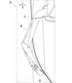
本発明の第1実施形態によるアタッチメント30の目標軌跡変更システム1は、図1に示す作業機械2のアタッチメント30の特定部位の目標軌跡71(図3参照)を変更するものである。目標軌跡変更システム1は、作業機械2と、携帯端末3と、カメラ4(周囲状況取得装置)と、を有している。 (First Embodiment)
(Configuration of target trajectory change system 1)
The targetlocus change system 1 of the attachment 30 according to the first embodiment of the present invention changes the target locus 71 (see FIG. 3) of a specific portion of the attachment 30 of the work machine 2 shown in FIG. The target trajectory changing system 1 has a work machine 2, a mobile terminal 3, and a camera 4 (surrounding condition acquisition device).
(目標軌跡変更システム1の構成)
本発明の第1実施形態によるアタッチメント30の目標軌跡変更システム1は、図1に示す作業機械2のアタッチメント30の特定部位の目標軌跡71(図3参照)を変更するものである。目標軌跡変更システム1は、作業機械2と、携帯端末3と、カメラ4(周囲状況取得装置)と、を有している。 (First Embodiment)
(Configuration of target trajectory change system 1)
The target
(作業機械の構成)
作業機械2は、アタッチメント30で作業を行う機械であり、例えば油圧ショベルである。作業機械2は、下部走行体21と、上部旋回体22と、旋回装置24と、アタッチメント30と、シリンダ40と、操作レバー51(図2参照)と、旋回角度センサ52と、傾斜角センサ60と、を有している。 (Structure of work machine)
Thework machine 2 is a machine that performs work with the attachment 30, and is, for example, a hydraulic excavator. The work machine 2 includes a lower traveling body 21, an upper swivel body 22, a swivel device 24, an attachment 30, a cylinder 40, an operation lever 51 (see FIG. 2), a swivel angle sensor 52, and an inclination angle sensor 60. And have.
作業機械2は、アタッチメント30で作業を行う機械であり、例えば油圧ショベルである。作業機械2は、下部走行体21と、上部旋回体22と、旋回装置24と、アタッチメント30と、シリンダ40と、操作レバー51(図2参照)と、旋回角度センサ52と、傾斜角センサ60と、を有している。 (Structure of work machine)
The
下部走行体21は、作業機械2を走行させる部分であり、例えばクローラを備える。上部旋回体22は、下部走行体21の上部に旋回可能に取り付けられる。上部旋回体22は、上部旋回体22の前部に設けられるキャブ23(運転室)を有している。旋回装置24は、下部走行体21に対して上部旋回体22を旋回させることが可能である。
The lower traveling body 21 is a part for traveling the work machine 2, and is provided with, for example, a crawler. The upper swivel body 22 is rotatably attached to the upper part of the lower traveling body 21. The upper swivel body 22 has a cab 23 (driver's cab) provided at the front portion of the upper swivel body 22. The swivel device 24 can swivel the upper swivel body 22 with respect to the lower traveling body 21.
アタッチメント30は、上下方向に回動可能に上部旋回体22に取り付けられる。アタッチメント30は、ブーム31と、アーム32と、バケット33(先端アタッチメント)と、を備える。ブーム31は、上下方向に回動可能に上部旋回体22に取り付けられる。アーム32は、上下方向に回動可能にブーム31に取り付けられる。バケット33は、上下方向に回動可能にアーム32に取り付けられる。バケット33は、作業対象(土砂など)の、掘削、保持、投下、ならし、すくい、などの作業を行う部分である。なお、バケット33は、アーム32に取り付けられる先端アタッチメントの一例であり、先端アタッチメントはこれに限定されず、ニブラやクランプアーム等であってもよい。また、バケット33の作業対象は、土砂でもよく、砂利でもよく、瓦礫や鉄屑などでもよい。バケット33の先端が移動可能な方向は、上部旋回体22の前後方向、および、上部旋回体22の上下方向である。アタッチメント30は、上部旋回体22の前後方向に伸縮する。また、アタッチメント30は、上部旋回体22の上下方向に回動する。
The attachment 30 is attached to the upper swing body 22 so as to be rotatable in the vertical direction. The attachment 30 includes a boom 31, an arm 32, and a bucket 33 (tip attachment). The boom 31 is attached to the upper swing body 22 so as to be rotatable in the vertical direction. The arm 32 is attached to the boom 31 so as to be rotatable in the vertical direction. The bucket 33 is attached to the arm 32 so as to be rotatable in the vertical direction. The bucket 33 is a part of a work target (earth and sand, etc.) for excavating, holding, dropping, leveling, scooping, and the like. The bucket 33 is an example of a tip attachment attached to the arm 32, and the tip attachment is not limited to this, and may be a nibbler, a clamp arm, or the like. Further, the work target of the bucket 33 may be earth and sand, gravel, rubble, iron scraps, and the like. The directions in which the tip of the bucket 33 can be moved are the front-rear direction of the upper swivel body 22 and the vertical direction of the upper swivel body 22. The attachment 30 expands and contracts in the front-rear direction of the upper swing body 22. Further, the attachment 30 rotates in the vertical direction of the upper swing body 22.
シリンダ40は、アタッチメント30を油圧で回動させることが可能である。シリンダ40は、油圧式の伸縮シリンダである。シリンダ40は、ブームシリンダ41と、アームシリンダ42と、バケットシリンダ43(先端アタッチメントシリンダ)と、を備える。
The cylinder 40 can rotate the attachment 30 hydraulically. The cylinder 40 is a hydraulic telescopic cylinder. The cylinder 40 includes a boom cylinder 41, an arm cylinder 42, and a bucket cylinder 43 (tip attachment cylinder).
ブームシリンダ41は、上部旋回体22に対してブーム31を回転駆動させる。ブームシリンダ41の基端部は、上部旋回体22に回動可能に取り付けられる。ブームシリンダ41の先端部は、ブーム31に回動可能に取り付けられる。
The boom cylinder 41 rotationally drives the boom 31 with respect to the upper swing body 22. The base end portion of the boom cylinder 41 is rotatably attached to the upper swing body 22. The tip of the boom cylinder 41 is rotatably attached to the boom 31.
アームシリンダ42は、ブーム31に対してアーム32を回転駆動させる。アームシリンダ42の基端部は、ブーム31に回動可能に取り付けられる。アームシリンダ42の先端部は、アーム32に回動可能に取り付けられる。
The arm cylinder 42 rotates and drives the arm 32 with respect to the boom 31. The base end portion of the arm cylinder 42 is rotatably attached to the boom 31. The tip of the arm cylinder 42 is rotatably attached to the arm 32.
バケットシリンダ43(先端アタッチメントシリンダ)は、アーム32に対してバケット33を回転駆動させる。バケットシリンダ43の基端部は、アーム32に回動可能に取り付けられる。バケットシリンダ43の先端部は、バケット33に回動可能に取り付けられたリンク部材34に、回動可能に取り付けられる。
The bucket cylinder 43 (tip attachment cylinder) rotationally drives the bucket 33 with respect to the arm 32. The base end portion of the bucket cylinder 43 is rotatably attached to the arm 32. The tip of the bucket cylinder 43 is rotatably attached to the link member 34 rotatably attached to the bucket 33.
操作レバー51は、旋回装置24およびアタッチメント30を動作させるためにオペレータにより操作される。操作レバー51は、例えばキャブ23内に設けられている。作業機械2が遠隔操縦される場合には、操作レバー51は、作業機械2の外部に設けられる。
The operation lever 51 is operated by an operator to operate the swivel device 24 and the attachment 30. The operation lever 51 is provided in, for example, the cab 23. When the work machine 2 is remotely controlled, the operation lever 51 is provided outside the work machine 2.
旋回角度センサ52は、下部走行体21に対する上部旋回体22の旋回角度θ(図12参照)を検出する。旋回角度センサ52は、例えば、エンコーダ、レゾルバ、又は、ジャイロセンサなどである。本実施形態では、上部旋回体22の前方が下部走行体21の前方と一致するときの上部旋回体22の旋回角度θを0°としている。
The turning angle sensor 52 detects the turning angle θ (see FIG. 12) of the upper turning body 22 with respect to the lower traveling body 21. The turning angle sensor 52 is, for example, an encoder, a resolver, a gyro sensor, or the like. In the present embodiment, the turning angle θ of the upper turning body 22 when the front of the upper turning body 22 coincides with the front of the lower traveling body 21 is set to 0 °.
傾斜角センサ60は、アタッチメント30の姿勢を検出する。傾斜角センサ60は、ブーム傾斜角センサ61と、アーム傾斜角センサ62と、バケット傾斜角センサ63と、を有している。
The tilt angle sensor 60 detects the posture of the attachment 30. The tilt angle sensor 60 includes a boom tilt angle sensor 61, an arm tilt angle sensor 62, and a bucket tilt angle sensor 63.
ブーム傾斜角センサ61は、ブーム31の姿勢を検出する。例えば、ブーム傾斜角センサ61は、水平線に対するブーム31の傾斜角度を取得するセンサでもよく、具体的には例えば傾斜(加速度)センサ等でもよい。この場合、ブーム傾斜角センサ61は、ブーム31に取り付けられる。ブーム傾斜角センサ61は、ブームフットピン(ブーム基端)の回転角度を検出する回転角度センサや、ブームシリンダ41のストローク量を検出するストロークセンサであってもよい。
The boom tilt angle sensor 61 detects the posture of the boom 31. For example, the boom tilt angle sensor 61 may be a sensor that acquires the tilt angle of the boom 31 with respect to the horizon, and specifically, for example, a tilt (acceleration) sensor or the like. In this case, the boom tilt angle sensor 61 is attached to the boom 31. The boom tilt angle sensor 61 may be a rotation angle sensor that detects the rotation angle of the boom foot pin (boom base end) or a stroke sensor that detects the stroke amount of the boom cylinder 41.
アーム傾斜角センサ62は、アーム32の姿勢を検出する。例えば、アーム傾斜角センサ62は、水平線に対するアーム32の傾斜角度を取得するセンサでもよく、具体的には例えば傾斜(加速度)センサ等でもよい。この場合、アーム傾斜角センサ62は、アーム32に取り付けられる。アーム傾斜角センサ62は、アーム連結ピン(アーム基端)の回転角度を検出する回転角度センサや、アームシリンダ42のストローク量を検出するストロークセンサであってもよい。
The arm tilt angle sensor 62 detects the posture of the arm 32. For example, the arm tilt angle sensor 62 may be a sensor that acquires the tilt angle of the arm 32 with respect to the horizon, and specifically, for example, a tilt (acceleration) sensor or the like. In this case, the arm tilt angle sensor 62 is attached to the arm 32. The arm tilt angle sensor 62 may be a rotation angle sensor that detects the rotation angle of the arm connecting pin (arm base end) or a stroke sensor that detects the stroke amount of the arm cylinder 42.
バケット傾斜角センサ63(先端アタッチメント傾斜角センサ)は、バケット33の姿勢を検出する。例えば、バケット傾斜角センサ63は、水平線に対するバケット33の傾斜角度を取得するセンサでもよく、具体的には例えば傾斜(加速度)センサ等でもよい。この場合、バケット傾斜角センサ63は、リンク部材34に取り付けられてもよく、バケット33に取り付けられてもよい。バケット傾斜角センサ63は、バケット連結ピン(バケット基端)の回転角度を検出する回転角度センサや、バケットシリンダ43のストローク量を検出するストロークセンサであってもよい。
The bucket tilt angle sensor 63 (tip attachment tilt angle sensor) detects the posture of the bucket 33. For example, the bucket tilt angle sensor 63 may be a sensor that acquires the tilt angle of the bucket 33 with respect to the horizon, and specifically, for example, a tilt (acceleration) sensor or the like. In this case, the bucket tilt angle sensor 63 may be attached to the link member 34 or may be attached to the bucket 33. The bucket tilt angle sensor 63 may be a rotation angle sensor that detects the rotation angle of the bucket connecting pin (bucket base end) or a stroke sensor that detects the stroke amount of the bucket cylinder 43.
(携帯端末の構成)
携帯端末3は、作業者(例えば作業現場にいる作業者)により操作される端末である。携帯端末3は、例えばタブレット端末でもよく、スマートフォン等でもよい。携帯端末3は、作業機械2と相互に通信可能である。 (Configuration of mobile terminal)
Themobile terminal 3 is a terminal operated by a worker (for example, a worker at a work site). The mobile terminal 3 may be, for example, a tablet terminal, a smartphone or the like. The mobile terminal 3 can communicate with the work machine 2.
携帯端末3は、作業者(例えば作業現場にいる作業者)により操作される端末である。携帯端末3は、例えばタブレット端末でもよく、スマートフォン等でもよい。携帯端末3は、作業機械2と相互に通信可能である。 (Configuration of mobile terminal)
The
(カメラの構成)
図1に示すように、カメラ4(周囲状況取得装置)は、作業機械2の周囲状況76(図3参照)を取得するものである。本実施形態において、カメラ4は、アタッチメント30の後方から、アタッチメント30の周囲状況76を取得できる位置に配置されている。なお、カメラ4は周囲状況取得装置の一例であり、周囲状況取得装置はこれに限定されず、ライダ(LIDAR;Light Detection and Ranging)等であってもよい。また、カメラ4は、作業機械2に設けられていてもよいし、作業機械2から離れた場所に設置されていてもよい。 (Camera configuration)
As shown in FIG. 1, the camera 4 (surrounding condition acquisition device) acquires the surrounding condition 76 (see FIG. 3) of thework machine 2. In the present embodiment, the camera 4 is arranged at a position where the surrounding condition 76 of the attachment 30 can be acquired from the rear of the attachment 30. The camera 4 is an example of a surrounding condition acquisition device, and the surrounding condition acquisition device is not limited to this, and may be a lidar (LIDAR; Light Detection and Ranging) or the like. Further, the camera 4 may be installed in the work machine 2 or may be installed in a place away from the work machine 2.
図1に示すように、カメラ4(周囲状況取得装置)は、作業機械2の周囲状況76(図3参照)を取得するものである。本実施形態において、カメラ4は、アタッチメント30の後方から、アタッチメント30の周囲状況76を取得できる位置に配置されている。なお、カメラ4は周囲状況取得装置の一例であり、周囲状況取得装置はこれに限定されず、ライダ(LIDAR;Light Detection and Ranging)等であってもよい。また、カメラ4は、作業機械2に設けられていてもよいし、作業機械2から離れた場所に設置されていてもよい。 (Camera configuration)
As shown in FIG. 1, the camera 4 (surrounding condition acquisition device) acquires the surrounding condition 76 (see FIG. 3) of the
(目標軌跡変更システムの回路構成)
目標軌跡変更システム1の回路図である図2に示すように、作業機械2は、コントローラ11と、作業機械側通信装置12と、記憶装置13と、を有している。コントローラ11は、目標点設定手段、目標軌跡再設定手段、および特定間隔変更手段として機能する(後述)。 (Circuit configuration of target trajectory change system)
As shown in FIG. 2, which is a circuit diagram of the targetlocus change system 1, the work machine 2 includes a controller 11, a work machine side communication device 12, and a storage device 13. The controller 11 functions as a target point setting means, a target trajectory resetting means, and a specific interval changing means (described later).
目標軌跡変更システム1の回路図である図2に示すように、作業機械2は、コントローラ11と、作業機械側通信装置12と、記憶装置13と、を有している。コントローラ11は、目標点設定手段、目標軌跡再設定手段、および特定間隔変更手段として機能する(後述)。 (Circuit configuration of target trajectory change system)
As shown in FIG. 2, which is a circuit diagram of the target
コントローラ11は、アタッチメント30(図1参照)の特定部位の目標軌跡71(図3参照)を設定する。図1に示すアタッチメント30の特定部位は、例えば、バケット33の先端でもよく、アーム32の先端等であってもよい。以下では、主に、アタッチメント30の特定部位がバケット33の先端である場合について説明する。また、図2に示すコントローラ11(目標点設定手段)は、目標軌跡71(図3参照)上の、特定間隔毎の目標点72を設定する。コントローラ11は、特定間隔毎の目標点72を、アタッチメント30(図1参照)の姿勢に関連付けた情報として設定する。ここで、アタッチメント30の姿勢には、上部旋回体22の旋回角度θ(図12参照)も含まれる。特定間隔は、特定の時間間隔(特定時間)であってもよいし、特定の距離間隔であってもよい。本実施形態では、特定間隔は、特定時間である。本実施形態において、特定時間は1秒である。
The controller 11 sets the target locus 71 (see FIG. 3) of the specific portion of the attachment 30 (see FIG. 1). The specific portion of the attachment 30 shown in FIG. 1 may be, for example, the tip of the bucket 33, the tip of the arm 32, or the like. Hereinafter, a case where the specific portion of the attachment 30 is the tip of the bucket 33 will be mainly described. Further, the controller 11 (target point setting means) shown in FIG. 2 sets the target points 72 at specific intervals on the target locus 71 (see FIG. 3). The controller 11 sets the target point 72 at each specific interval as information associated with the posture of the attachment 30 (see FIG. 1). Here, the posture of the attachment 30 also includes the turning angle θ (see FIG. 12) of the upper turning body 22. The specific interval may be a specific time interval (specific time) or a specific distance interval. In this embodiment, the specific interval is a specific time. In this embodiment, the specific time is 1 second.
ここで、本実施形態では、実際に作業機械2(図1参照)を動作させるティーチングにより、目標軌跡71(図3参照)が設定される(オンラインティーチング)。具体的には、オペレータが操作レバー51を操作することで、旋回装置24およびアタッチメント30を動作させる。このときの上部旋回体22の旋回角度θ(図12参照)が、旋回角度センサ52により検出される。また、このときのアタッチメント30の姿勢が、傾斜角センサ60により検出される。コントローラ11は、検出した上部旋回体22(図1参照)の旋回角度θ、および、検出したアタッチメント30の姿勢に基づいて、目標軌跡71(図3参照)を設定する。ここでの特定間隔(さらに詳しくは特定時間)は、旋回角度センサ52および傾斜角センサ60の検出値のサンプリング間隔(さらに詳しくはサンプリング時間)である。
Here, in the present embodiment, the target locus 71 (see FIG. 3) is set by the teaching that actually operates the work machine 2 (see FIG. 1) (online teaching). Specifically, the operator operates the operating lever 51 to operate the swivel device 24 and the attachment 30. The turning angle θ (see FIG. 12) of the upper turning body 22 at this time is detected by the turning angle sensor 52. Further, the posture of the attachment 30 at this time is detected by the tilt angle sensor 60. The controller 11 sets the target locus 71 (see FIG. 3) based on the detected turning angle θ of the upper swing body 22 (see FIG. 1) and the detected posture of the attachment 30. The specific interval (more specifically, the specific time) here is the sampling interval (more specifically, the sampling time) of the detection values of the turning angle sensor 52 and the tilt angle sensor 60.
なお、作業機械2が実際に動作させられることなく、上部旋回体22の旋回角度θ(図12参照)の情報およびアタッチメント30の姿勢の情報がコントローラ11に入力されることで、目標軌跡71(図3参照)が設定されてもよい(オフラインティーチング)。この場合、例えば、特定間隔毎の情報がコントローラ11に入力されることで、目標軌跡71(図3参照)が設定される。
The target locus 71 (see FIG. 12) by inputting the information on the turning angle θ (see FIG. 12) of the upper turning body 22 and the information on the posture of the attachment 30 to the controller 11 without actually operating the work machine 2. (See FIG. 3) may be set (offline teaching). In this case, for example, the target locus 71 (see FIG. 3) is set by inputting information for each specific interval to the controller 11.
コントローラ11は、目標軌跡71(図4参照)および目標点72(図4参照)に基づいて、自動運転指令を生成する。自動運転指令は、旋回装置24およびアタッチメント30を自動で動作させるための指令である。そして、コントローラ11は、自動運転指令に基づいて、旋回装置24およびアタッチメント30を自動で動作させることが可能である。作業機械2は、自動運転指令に基づいて自動運転されることになる。
The controller 11 generates an automatic operation command based on the target locus 71 (see FIG. 4) and the target point 72 (see FIG. 4). The automatic operation command is a command for automatically operating the turning device 24 and the attachment 30. Then, the controller 11 can automatically operate the turning device 24 and the attachment 30 based on the automatic operation command. The work machine 2 will be automatically operated based on the automatic operation command.
作業機械側通信装置12は、携帯端末3(さらに詳しくは後述する携帯端末側通信装置16)と通信可能である。記憶装置13は、コントローラ11が設定した目標軌跡71(図4参照)および目標点72(図4参照)を記憶可能である。
The work machine side communication device 12 can communicate with the mobile terminal 3 (more specifically, the mobile terminal side communication device 16 described later). The storage device 13 can store the target locus 71 (see FIG. 4) and the target point 72 (see FIG. 4) set by the controller 11.
携帯端末3は、携帯端末側コントローラ15と、携帯端末側通信装置16と、携帯端末側記憶装置17と、タッチパネル18と、表示装置19と、警告装置20と、を有している。携帯端末側コントローラ15は、対象点選択手段、範囲設定手段、対象点移動手段、変更開始点選択手段、変更終了点選択手段、第1目標点移動手段、第2目標点移動手段、対象アタッチメント選択手段、および目標姿勢変更手段として機能する(後述)。
The mobile terminal 3 has a mobile terminal side controller 15, a mobile terminal side communication device 16, a mobile terminal side storage device 17, a touch panel 18, a display device 19, and a warning device 20. The mobile terminal side controller 15 has a target point selection means, a range setting means, a target point moving means, a change start point selection means, a change end point selection means, a first target point moving means, a second target point moving means, and a target attachment selection. It functions as a means and a means for changing the target posture (described later).
携帯端末側通信装置16は、作業機械2の作業機械側通信装置12と通信可能である。携帯端末側コントローラ15は、携帯端末側通信装置16を介して、作業機械2から目標軌跡71(図4参照)および目標点72(図4参照)を受信する。表示装置19の表示画面を示す図である図3に示すように、表示装置19は、目標軌跡71および目標点72(図4参照)を表示する。表示装置19は、例えば携帯端末3のディスプレイなどである。なお、図3では、目標点72(図4参照)を図示していない。また、図3に示すように、表示装置19は、カメラ4(図1参照)が取得した周囲状況76を、目標軌跡71および目標点72(図4参照)に重畳させて表示する。
The mobile terminal side communication device 16 can communicate with the work machine side communication device 12 of the work machine 2. The mobile terminal side controller 15 receives the target locus 71 (see FIG. 4) and the target point 72 (see FIG. 4) from the work machine 2 via the mobile terminal side communication device 16. As shown in FIG. 3, which is a diagram showing the display screen of the display device 19, the display device 19 displays the target locus 71 and the target point 72 (see FIG. 4). The display device 19 is, for example, a display of a mobile terminal 3. Note that FIG. 3 does not show the target point 72 (see FIG. 4). Further, as shown in FIG. 3, the display device 19 superimposes and displays the surrounding situation 76 acquired by the camera 4 (see FIG. 1) on the target locus 71 and the target point 72 (see FIG. 4).
なお、図3に示す目標軌跡71は、持ち上げ旋回時のものであるが、これに限定されず、復帰旋回時のもの等であってもよい。持ち上げ旋回とは、バケット33に掬われた作業対象(土砂等)がバケット33に保持された状態で、上部旋回体22が旋回する動作である。復帰旋回とは、バケット33に保持されていた作業対象(土砂等)がバケット33から排出された後に、上部旋回体22が旋回し、バケット33が掘削位置に復帰する動作である。
Note that the target locus 71 shown in FIG. 3 is for a lift turn, but is not limited to this, and may be a return turn or the like. The lifting swivel is an operation in which the upper swivel body 22 swivels while the work target (earth and sand or the like) scooped by the bucket 33 is held by the bucket 33. The return turning is an operation in which the upper swivel body 22 swivels after the work target (earth and sand or the like) held in the bucket 33 is discharged from the bucket 33, and the bucket 33 returns to the excavation position.
図2に戻って、携帯端末側記憶装置17は、作業機械2から受信した目標軌跡71(図4参照)および目標点72(図4参照)を記憶可能である。タッチパネル18(入力装置)は、作業者からの入力を受け付ける。なお、タッチパネル18は、入力装置の一例であり、入力装置はこれに限定されず、例えば、キーボード等であってもよい。
Returning to FIG. 2, the mobile terminal side storage device 17 can store the target locus 71 (see FIG. 4) and the target point 72 (see FIG. 4) received from the work machine 2. The touch panel 18 (input device) receives input from an operator. The touch panel 18 is an example of an input device, and the input device is not limited to this, and may be, for example, a keyboard or the like.
警告装置20は、図3に示す周囲状況76に含まれる障害物と目標軌跡71との距離が所定値以下の場合に、警告を出力する(発生させる)。例えば、周囲状況76が更新された際に、新たに出現した障害物と目標軌跡71との距離が所定値以下の場合に、警告装置20は、警告を出力する。警告装置20は、音声で警告を出力するスピーカでもよく、振動するバイブレータでもよく、表示装置19の表示によって警告を行なうものであってもよい。
The warning device 20 outputs (generates) a warning when the distance between the obstacle included in the surrounding situation 76 shown in FIG. 3 and the target locus 71 is equal to or less than a predetermined value. For example, when the surrounding condition 76 is updated, the warning device 20 outputs a warning when the distance between the newly appearing obstacle and the target locus 71 is equal to or less than a predetermined value. The warning device 20 may be a speaker that outputs a warning by voice, a vibrating vibrator, or a device that gives a warning by the display of the display device 19.
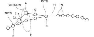
表示装置19に表示された目標軌跡71および目標点72を図4に示す。上記のように、例えばティーチングなどによって目標軌跡71が設定されるところ、作業者が、目標軌跡71の一部を変更したい場合がある。例えば、作業現場によっては、障害物を避ける等の理由によって、目標軌跡71の一部を、その作業現場に即したものに、作業者が変更したい場合がある。
FIG. 4 shows the target locus 71 and the target point 72 displayed on the display device 19. As described above, where the target locus 71 is set by, for example, teaching, the operator may want to change a part of the target locus 71. For example, depending on the work site, the worker may want to change a part of the target locus 71 to one suitable for the work site for reasons such as avoiding obstacles.
このような場合、携帯端末3に(図2参照)おいて、変更モードが起動される。この変更モードにおいて、携帯端末側コントローラ15(対象点選択手段)(図2参照)は、複数の目標点72のいずれかを変更対象点73として作業者に選択させる。警告装置20(図2参照)からの警告により、障害物に接触しそうな目標点72の移動が、作業者に促される。作業者は、タッチパネル18(図2参照)を操作して、変更対象点73を選択する。具体的には、作業者は、変更対象点73としたい目標点72が表示されたタッチパネル18の部位をタッチする。図4においては、矢印Aで示す目標点72が変更対象点73として選択されている。
In such a case, the change mode is activated on the mobile terminal 3 (see FIG. 2). In this change mode, the mobile terminal side controller 15 (target point selection means) (see FIG. 2) causes the operator to select one of the plurality of target points 72 as the change target point 73. The warning from the warning device 20 (see FIG. 2) prompts the operator to move the target point 72 that is likely to come into contact with an obstacle. The operator operates the touch panel 18 (see FIG. 2) to select the change target point 73. Specifically, the operator touches the portion of the touch panel 18 on which the target point 72 to be changed as the target point 73 is displayed. In FIG. 4, the target point 72 indicated by the arrow A is selected as the change target point 73.
次に、携帯端末側コントローラ15(変更開始点選択手段)(図2参照)は、変更対象点73の前方に位置する複数の目標点72のいずれかを変更開始点74として作業者に選択させる。作業者は、タッチパネル18(図2参照)を操作して、変更開始点74を選択する。さらに詳しくは、変更開始点74の選択は、表示装置19に表示されている所望の目標点72に重畳するタッチパネル18の部位をタッチすることで行われる。図4においては、矢印Bで示す、変更対象点73の1つ隣の目標点72が変更開始点74として選択されている。
Next, the mobile terminal side controller 15 (change start point selection means) (see FIG. 2) causes the operator to select one of the plurality of target points 72 located in front of the change target point 73 as the change start point 74. .. The operator operates the touch panel 18 (see FIG. 2) to select the change start point 74. More specifically, the selection of the change start point 74 is performed by touching the portion of the touch panel 18 superimposed on the desired target point 72 displayed on the display device 19. In FIG. 4, the target point 72 immediately adjacent to the change target point 73 indicated by the arrow B is selected as the change start point 74.
次に、携帯端末側コントローラ15(変更終了点選択手段)(図2参照)は、変更対象点73の後方に位置する複数の目標点72のいずれかを変更終了点75として作業者に選択させる。作業者は、タッチパネル18(図2参照)を操作して、変更終了点75を選択する。さらに詳しくは、変更終了点75の選択は、表示装置19に表示されている所望の目標点72に重畳するタッチパネル18の部位をタッチすることで行われる。図4においては、矢印Cで示す、変更対象点73のすぐ隣の目標点72が変更終了点75として選択されている。
Next, the mobile terminal side controller 15 (change end point selection means) (see FIG. 2) causes the operator to select one of the plurality of target points 72 located behind the change target point 73 as the change end point 75. .. The operator operates the touch panel 18 (see FIG. 2) to select the change end point 75. More specifically, the selection of the change end point 75 is performed by touching the portion of the touch panel 18 superimposed on the desired target point 72 displayed on the display device 19. In FIG. 4, the target point 72 immediately adjacent to the change target point 73 indicated by the arrow C is selected as the change end point 75.
次に、携帯端末側コントローラ15(範囲設定手段)(図2参照)は、変更対象点73を移動可能な範囲を移動可能範囲Eとして設定する。移動可能範囲Eは、変更対象点73、変更開始点74、および変更終了点75の少なくともいずれかにおけるアタッチメント30(図2参照)の姿勢の情報に基づいて設定される。例えば「変更開始点74における」アタッチメント30の姿勢の情報とは、アタッチメント30の特定部位が変更開始点74に配置されたと仮定したときの、アタッチメント30の姿勢の情報である(変更対象点73および変更終了点75についても同様)。移動可能範囲Eは、上部旋回体22に関する方向に基づいて設定されてもよい(第3実施形態を参照)。ここでは、移動可能範囲Eが、変更対象点73、変更開始点74、および変更終了点75の少なくともいずれかにおけるアタッチメント30の姿勢の情報に基づいて設定される場合について説明する。
Next, the mobile terminal side controller 15 (range setting means) (see FIG. 2) sets the movable range of the change target point 73 as the movable range E. The movable range E is set based on the posture information of the attachment 30 (see FIG. 2) at at least one of the change target point 73, the change start point 74, and the change end point 75. For example, the posture information of the attachment 30 "at the change start point 74" is the posture information of the attachment 30 when it is assumed that the specific portion of the attachment 30 is arranged at the change start point 74 (change target point 73 and the change target point 73 and). The same applies to the change end point 75). The movable range E may be set based on the direction with respect to the upper swing body 22 (see the third embodiment). Here, a case where the movable range E is set based on the posture information of the attachment 30 at at least one of the change target point 73, the change start point 74, and the change end point 75 will be described.
図4に示す例では、矢印Aで示す変更対象点73の前方および後方にそれぞれ目標点72がある。この例では、移動可能範囲Eは、変更開始点74および変更終了点75の両方におけるアタッチメント30の姿勢の情報に基づいて設定される。一方、変更対象点73が、目標軌跡71の両端のどちらかに位置する目標点72である場合、目標点72の前方および後方のどちらかにしか目標点72がない。この場合、移動可能範囲Eは、変更開始点74および変更終了点75のどちらか一方におけるアタッチメント30(図2参照)の姿勢の情報に基づいて設定される。例えば、移動可能範囲Eは、アタッチメント30の特定部位が変更対象点73に配置されたと仮定したときに、アタッチメント30が取り得る姿勢(さらに詳しくは物理的に取り得る姿勢)に基づいて設定されてもよい。
In the example shown in FIG. 4, the target points 72 are located in front of and behind the change target point 73 indicated by the arrow A, respectively. In this example, the movable range E is set based on the posture information of the attachment 30 at both the change start point 74 and the change end point 75. On the other hand, when the change target point 73 is a target point 72 located at either end of the target locus 71, the target point 72 is located only in front of or behind the target point 72. In this case, the movable range E is set based on the posture information of the attachment 30 (see FIG. 2) at either the change start point 74 or the change end point 75. For example, the movable range E is set based on the posture that the attachment 30 can take (more specifically, the posture that can be physically taken) when it is assumed that the specific portion of the attachment 30 is arranged at the change target point 73. May be good.
アタッチメント30の姿勢の情報に基づいて移動可能範囲Eが設定される場合の、移動可能範囲Eの具体例は、次の通りである。上述したように、本実施形態では、特定時間は1秒である。そのため、アタッチメント30(図2参照)の姿勢は、変更開始点74の姿勢から、移動後の変更対象点73の姿勢に1秒で変化した後に、移動後の変更対象点73の姿勢から、変更終了点75の姿勢に1秒で変化する必要がある。このような制約の上で、変更対象点73を移動させることが可能な範囲が、移動可能範囲Eである。具体的には、移動可能範囲Eは、変更開始点74および変更終了点75における、シリンダ40(図1参照)のロッドの伸縮速度や、上部旋回体22(図1参照)の旋回速度、シリンダ40のロッドの可動範囲に基づいて設定される。さらに詳しくは、変更開始点74および変更終了点75におけるシリンダ40のロッドの伸縮速度などに基づいて、変更対象点73における、アタッチメント30の取り得る姿勢が算出され、この姿勢に基づいて移動可能範囲Eが設定される。
A specific example of the movable range E when the movable range E is set based on the posture information of the attachment 30 is as follows. As described above, in the present embodiment, the specific time is 1 second. Therefore, the posture of the attachment 30 (see FIG. 2) changes from the posture of the change start point 74 to the posture of the change target point 73 after movement in 1 second, and then changes from the posture of the change target point 73 after movement. It is necessary to change to the posture of the end point 75 in 1 second. Under such restrictions, the range in which the change target point 73 can be moved is the movable range E. Specifically, the movable range E includes the expansion / contraction speed of the rod of the cylinder 40 (see FIG. 1), the turning speed of the upper swing body 22 (see FIG. 1), and the cylinder at the change start point 74 and the change end point 75. It is set based on the movable range of 40 rods. More specifically, the possible posture of the attachment 30 at the change target point 73 is calculated based on the expansion / contraction speed of the rod of the cylinder 40 at the change start point 74 and the change end point 75, and the movable range is calculated based on this posture. E is set.
次に、携帯端末側コントローラ15(対象点移動手段)(図2参照)は、移動可能範囲E内において変更対象点73を作業者に移動させる。この移動の具体例は、次の通りである。
Next, the mobile terminal side controller 15 (target point moving means) (see FIG. 2) moves the change target point 73 to the operator within the movable range E. Specific examples of this movement are as follows.
[具体例1]表示装置19は、図4に示すような目標軌跡71および目標点72を含む画像を表示する。この表示において、作業者は、例えばタッチパネル18(図2参照)などの操作を行うことにより、目標点72から変更対象点73を選択し、変更対象点73を移動させてもよい(図5参照)。
[Specific example 1] The display device 19 displays an image including the target locus 71 and the target point 72 as shown in FIG. In this display, the operator may select the change target point 73 from the target point 72 and move the change target point 73 by performing an operation such as the touch panel 18 (see FIG. 2) (see FIG. 5). ).
作業者の操作により、移動可能範囲E内から移動可能範囲E外に変更対象点73が移動させられようとする場合がある。この場合、移動可能範囲E内から移動可能範囲E外に変更対象点73が移動させられようとしていることを、作業者に直感的に認識させることが好ましい。具体的には、この場合、携帯端末側コントローラ15(図2参照)は、表示装置19(図2参照)の画像の表示態様を変化させる。具体的には例えば、表示装置19は、文字や図形などを表示してもよい。例えば、表示装置19は、目標軌跡71や変更対象点73の表示態様を変化させてもよい。例えば、表示装置19は、変更対象点73を半透明に表示してもよく、変更対象点73の色彩を変更してもよく、目標軌跡71の表示態様を変化させてもよい。
The change target point 73 may be moved from within the movable range E to outside the movable range E by the operation of the operator. In this case, it is preferable to make the operator intuitively recognize that the change target point 73 is about to be moved from the movable range E to the outside of the movable range E. Specifically, in this case, the mobile terminal side controller 15 (see FIG. 2) changes the display mode of the image of the display device 19 (see FIG. 2). Specifically, for example, the display device 19 may display characters, figures, and the like. For example, the display device 19 may change the display mode of the target locus 71 and the change target point 73. For example, the display device 19 may display the change target point 73 semi-transparently, change the color of the change target point 73, or change the display mode of the target locus 71.
[具体例2]図3に示すように、表示装置19(図3参照)は、アタッチメント30(図1参照)および目標軌跡71を含む画像を表示する。作業者は、操作を行うことで、アタッチメント30(図1参照)の画像を移動させる。この画像の移動に伴って、変更対象点73が変更されてもよい。この具体例2の詳細は、例えば次の通りである。
[Specific Example 2] As shown in FIG. 3, the display device 19 (see FIG. 3) displays an image including the attachment 30 (see FIG. 1) and the target locus 71. The operator moves the image of the attachment 30 (see FIG. 1) by performing an operation. The change target point 73 may be changed as the image moves. The details of the specific example 2 are as follows, for example.
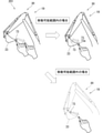
まず、携帯端末側コントローラ15(対象アタッチメント選択手段)(図2参照)は、図1に示すブーム31、アーム32、および、バケット33の少なくとも1つを対象アタッチメントとして作業者に選択させる。作業者は、タッチパネル18(図2参照)を操作して、対象アタッチメントを選択する。ここで、持ち上げ旋回においては、作業対象(土砂等)を保持した状態のバケット33を上下方向に回動させると、作業対象がこぼれる恐れがある。そこで、図3においては、アーム32(図1参照)に対応するアーム画像78が選択されることで、アーム32が対象アタッチメントとして選択されている。なお、ブーム31(図1参照)にはブーム画像77が対応し、バケット33(図1参照)にはバケット画像79(先端アタッチメント画像)が対応している。
First, the mobile terminal side controller 15 (target attachment selection means) (see FIG. 2) causes the operator to select at least one of the boom 31, arm 32, and bucket 33 shown in FIG. 1 as the target attachment. The operator operates the touch panel 18 (see FIG. 2) to select the target attachment. Here, in the lifting and turning, if the bucket 33 holding the work target (earth and sand or the like) is rotated in the vertical direction, the work target may spill. Therefore, in FIG. 3, the arm image 78 corresponding to the arm 32 (see FIG. 1) is selected, so that the arm 32 is selected as the target attachment. The boom 31 (see FIG. 1) corresponds to the boom image 77, and the bucket 33 (see FIG. 1) corresponds to the bucket image 79 (tip attachment image).
図1に示すブーム31、アーム32、および、バケット33の少なくとも1つが対象アタッチメントとして選択されると、選択された対象アタッチメントに関する情報が、図3に示す表示装置19に表示される。例えば、アーム32が対象アタッチメントとして選択された場合について説明する。表示装置19の表示画面に、対象アタッチメントがアーム32であることを示す文字画像81が表示される。表示装置19に、現在設定されているアーム角度の数値を示す数値画像82が表示される。図3においては、アーム角度の数値は「100」である。また、表示装置19に、アーム角度の数値を増加させるための増加ボタン画像83と、アーム角度の数値を減少させるための減少ボタン画像84と、が表示される。
When at least one of the boom 31, arm 32, and bucket 33 shown in FIG. 1 is selected as the target attachment, information about the selected target attachment is displayed on the display device 19 shown in FIG. For example, a case where the arm 32 is selected as the target attachment will be described. On the display screen of the display device 19, a character image 81 indicating that the target attachment is the arm 32 is displayed. A numerical image 82 showing a numerical value of the currently set arm angle is displayed on the display device 19. In FIG. 3, the numerical value of the arm angle is "100". Further, the display device 19 displays an increase button image 83 for increasing the numerical value of the arm angle and a decrease button image 84 for decreasing the numerical value of the arm angle.
次に、携帯端末側コントローラ15(目標姿勢変更手段)(図2参照)は、対象アタッチメントの目標姿勢を作業者に変更させることで、図4に示す変更対象点73を移動させる。さらに詳しくは、携帯端末側コントローラ15は、対象アタッチメントの目標姿勢を作業者に変更させ(目標姿勢変更手段としての機能)、目標姿勢の変更に基づいて変更対象点73を移動させる(対象点移動手段としての機能)。具体的には例えば、作業者は、図3に示す増加ボタン画像83や減少ボタン画像84をタッチして、アーム角度の数値を変更する。対象アタッチメントの目標姿勢が変更される結果、図4に示す変更対象点73が移動する。
Next, the mobile terminal side controller 15 (target posture changing means) (see FIG. 2) moves the change target point 73 shown in FIG. 4 by causing the worker to change the target posture of the target attachment. More specifically, the controller 15 on the mobile terminal side causes the worker to change the target posture of the target attachment (function as a target posture changing means), and moves the change target point 73 based on the change of the target posture (target point movement). Function as a means). Specifically, for example, the operator touches the increase button image 83 or the decrease button image 84 shown in FIG. 3 to change the numerical value of the arm angle. As a result of changing the target posture of the target attachment, the change target point 73 shown in FIG. 4 moves.
作業者により、対象アタッチメントの目標姿勢が変更されたときに、アタッチメント30の特定部位の位置が移動可能範囲E内から移動可能範囲E外に移動させられようとする場合がある。この場合、特定部位の位置が移動可能範囲E内から移動可能範囲E外に移動したことを、作業者に直感的に認識させることが好ましい。具体的には、この場合、携帯端末側コントローラ15は、アタッチメント30の表示態様を変化させてもよく、対象アタッチメントの表示態様を変化させてもよく、変更対象点73の表示態様を変化させてもよく、目標軌跡71の表示態様を変化させてもよい。具体的には例えば、携帯端末側コントローラ15は、対象アタッチメントの表示を半透明に変化させてもよい。
When the target posture of the target attachment is changed by the worker, the position of the specific part of the attachment 30 may be moved from the movable range E to the outside of the movable range E. In this case, it is preferable to make the operator intuitively recognize that the position of the specific portion has moved from the movable range E to the outside of the movable range E. Specifically, in this case, the mobile terminal side controller 15 may change the display mode of the attachment 30, the display mode of the target attachment may be changed, or the display mode of the change target point 73 may be changed. Alternatively, the display mode of the target locus 71 may be changed. Specifically, for example, the mobile terminal side controller 15 may change the display of the target attachment semi-transparently.
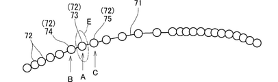
変更対象点73が移動された後における、表示装置19(図3参照)に表示された目標軌跡71および目標点72を図5に示す。変更対象点73が移動された結果、目標軌跡71の一部が再設定(変更)される。さらに詳しくは、作業機械2のコントローラ11は、移動後の変更対象点73、変更開始点74、および、変更終了点75を、携帯端末3から受信する。コントローラ11(目標軌跡再設定手段)は、移動後の変更対象点73を目標軌跡71が通るように、変更開始点74から変更終了点75までの間で、目標軌跡71を再設定する(再設定された目標軌跡71aを参照)。
FIG. 5 shows the target locus 71 and the target point 72 displayed on the display device 19 (see FIG. 3) after the change target point 73 has been moved. As a result of moving the change target point 73, a part of the target locus 71 is reset (changed). More specifically, the controller 11 of the work machine 2 receives the change target point 73, the change start point 74, and the change end point 75 after the movement from the mobile terminal 3. The controller 11 (target locus resetting means) resets the target locus 71 between the change start point 74 and the change end point 75 so that the target locus 71 passes through the change target point 73 after movement (re-setting). See the set target trajectory 71a).
ここで、表示装置19に表示された目標軌跡71および目標点72を、図7に示す。図7に示すように、変更対象点73から複数(例えば2つ)前の目標点72が変更開始点74として選択され、変更対象点73から複数(例えば2つ)後ろの目標点72が変更終了点75として選択された場合を考える。
Here, the target locus 71 and the target point 72 displayed on the display device 19 are shown in FIG. As shown in FIG. 7, a plurality of (for example, two) target points 72 before the change target point 73 are selected as the change start points 74, and a plurality of (for example, two) target points 72 after the change target point 73 are changed. Consider the case where it is selected as the end point 75.
変更対象点73の前方や後方に近い目標点72を変更開始点74や変更終了点75として選択する場合(場合A)と、変更対象点73から前方や後方に遠い目標点72を変更開始点74や変更終了点75として選択する場合(場合B)とを比べる。場合Aに比べ、場合Bの方が、変更開始点74から変更対象点73を経由して変更終了点75まで移動する時間が長くなる。この時間が長いほど、変更対象点73の移動可能範囲Eが広くなる。よって、変更開始点74や変更終了点75として選択される目標点72が変更対象点73から前方や後方に遠いほど、変更対象点73の移動可能範囲Eを広くすることができる。
When the target point 72 near the front or rear of the change target point 73 is selected as the change start point 74 or the change end point 75 (Case A), the target point 72 far from the change target point 73 forward or backward is the change start point. Compare with the case of selecting 74 or the change end point 75 (case B). In case B, the time required to move from the change start point 74 to the change end point 75 via the change target point 73 is longer than in case A. The longer this time is, the wider the movable range E of the change target point 73 becomes. Therefore, as the target point 72 selected as the change start point 74 or the change end point 75 is farther forward or backward from the change target point 73, the movable range E of the change target point 73 can be widened.
(目標軌跡変更システムの動作)
次に、目標軌跡変更処理のフローチャートである図8を用いて、目標軌跡変更システム1(図2参照)の動作を説明する。以下では、フローチャートのステップS1~S13については図8を参照して説明する。 (Operation of target trajectory change system)
Next, the operation of the target trajectory changing system 1 (see FIG. 2) will be described with reference to FIG. 8, which is a flowchart of the target trajectory changing process. In the following, steps S1 to S13 of the flowchart will be described with reference to FIG.
まず、図2に示す携帯端末3の携帯端末側コントローラ15は、変更モードを起動させる(ステップS1)。携帯端末3の携帯端末側記憶装置17には、作業機械2から受信した目標軌跡71(図4参照)および目標点72(図4参照)が記憶されている。次に、携帯端末側コントローラ15は、目標軌跡71および目標点72を表示装置19に表示させる(ステップS2)。このとき、図3に示すように、表示装置19には、周囲状況76が重畳されて表示される。次に、図2に示す携帯端末側コントローラ15は、周囲状況76(図3参照)に含まれる障害物と目標軌跡71(図3参照)との距離が所定値以下であるか否かを判定する(ステップS3)。
First, the mobile terminal side controller 15 of the mobile terminal 3 shown in FIG. 2 activates the change mode (step S1). The target locus 71 (see FIG. 4) and the target point 72 (see FIG. 4) received from the work machine 2 are stored in the mobile terminal side storage device 17 of the mobile terminal 3. Next, the mobile terminal side controller 15 causes the display device 19 to display the target locus 71 and the target point 72 (step S2). At this time, as shown in FIG. 3, the surrounding situation 76 is superimposed and displayed on the display device 19. Next, the mobile terminal side controller 15 shown in FIG. 2 determines whether or not the distance between the obstacle included in the surrounding situation 76 (see FIG. 3) and the target locus 71 (see FIG. 3) is equal to or less than a predetermined value. (Step S3).
携帯端末側コントローラ15は、ステップS3において、周囲状況76(図3参照)に含まれる障害物と目標軌跡71(図3参照)との距離が所定値以下であると判定した場合には(S3:YES)、警告装置20から警告を発生させる(ステップS4)。そして、携帯端末側コントローラ15は、ステップS5に進む。一方、携帯端末側コントローラ15は、ステップS3において、周囲状況76(図3参照)に含まれる障害物と目標軌跡71(図3参照)との距離が所定値以下でないと判定した場合には(S3:NO)、ステップS5に進む。
When the mobile terminal side controller 15 determines in step S3 that the distance between the obstacle included in the surrounding condition 76 (see FIG. 3) and the target locus 71 (see FIG. 3) is equal to or less than a predetermined value (S3). : YES), a warning is generated from the warning device 20 (step S4). Then, the mobile terminal side controller 15 proceeds to step S5. On the other hand, when the mobile terminal side controller 15 determines in step S3 that the distance between the obstacle included in the surrounding condition 76 (see FIG. 3) and the target locus 71 (see FIG. 3) is not equal to or less than a predetermined value (see FIG. 3). S3: NO), the process proceeds to step S5.
ステップS5では、携帯端末側コントローラ15は、変更対象点73(図4参照)を作業者に選択させる(ステップS5)。次に、携帯端末側コントローラ15は、変更開始点74(図4参照)および変更終了点75(図4参照)を作業者に選択させる(ステップS6)。
In step S5, the mobile terminal side controller 15 causes the operator to select the change target point 73 (see FIG. 4) (step S5). Next, the mobile terminal side controller 15 causes the operator to select the change start point 74 (see FIG. 4) and the change end point 75 (see FIG. 4) (step S6).
次に、携帯端末側コントローラ15は、移動可能範囲Eを設定する(ステップS7)。次に、携帯端末側コントローラ15は、対象アタッチメントを作業者に選択させる(ステップS8)。そして、携帯端末側コントローラ15は、対象アタッチメントの目標姿勢を作業者に変更させる(ステップS9)。
Next, the mobile terminal side controller 15 sets the movable range E (step S7). Next, the mobile terminal side controller 15 causes the operator to select the target attachment (step S8). Then, the mobile terminal side controller 15 causes the worker to change the target posture of the target attachment (step S9).
次に、携帯端末側コントローラ15は、変更後の対象アタッチメントの目標姿勢が移動可能範囲E(図4参照)内であるか否かを判定する(ステップS10)。携帯端末側コントローラ15は、ステップS10において、変更後の対象アタッチメントの目標姿勢が移動可能範囲E内でないと判定した場合には(S10:NO)、ステップS8に戻る(ステップS9に戻ってもよい)。作業者は、変更後の対象アタッチメントの目標姿勢が移動可能範囲E内に収まるように、対象アタッチメントの目標姿勢をさらに変更することになる。なお、この例では、対象アタッチメントの目標姿勢は、移動可能範囲E外に変更された後、移動可能範囲E内に収まるように変えられるが、対象アタッチメントの目標姿勢は、移動可能範囲E内にのみ変更可能とされてもよい。
Next, the mobile terminal side controller 15 determines whether or not the target posture of the changed target attachment is within the movable range E (see FIG. 4) (step S10). When the mobile terminal side controller 15 determines in step S10 that the target posture of the changed target attachment is not within the movable range E (S10: NO), the mobile terminal side controller 15 returns to step S8 (may return to step S9). ). The worker will further change the target posture of the target attachment so that the changed target posture of the target attachment is within the movable range E. In this example, the target posture of the target attachment is changed to be within the movable range E after being changed to the outside of the movable range E, but the target posture of the target attachment is within the movable range E. Only may be changeable.
一方、携帯端末側コントローラ15は、ステップS10において、変更後の対象アタッチメントの目標姿勢が移動可能範囲E(図4参照)内であると判定した場合には(S10:YES)、ステップS11に進む。次に、携帯端末側コントローラ15は、図6に示すように、バケット33の先端を目標軌跡71上に位置させながらアタッチメント30が動く動画を表示装置19に表示させる(ステップS11)。
On the other hand, if the mobile terminal side controller 15 determines in step S10 that the target posture of the changed target attachment is within the movable range E (see FIG. 4) (S10: YES), the process proceeds to step S11. .. Next, as shown in FIG. 6, the mobile terminal side controller 15 causes the display device 19 to display a moving image in which the attachment 30 moves while the tip of the bucket 33 is positioned on the target locus 71 (step S11).
次に、図2に示す携帯端末側コントローラ15は、目標軌跡71(図3参照)の変更の終了を作業者が指示したか否かを判定する(ステップS12)。携帯端末側コントローラ15は、ステップS12において、変更の終了を作業者が指示していないと判定した場合には(S12:NO)、ステップS8に戻る。一方、携帯端末側コントローラ15は、ステップS12において、変更の終了を作業者が指示したと判定した場合には(S12:YES)、変更内容を携帯端末側記憶装置17に保存し(ステップS13)、本フローを終了する。
Next, the mobile terminal side controller 15 shown in FIG. 2 determines whether or not the operator has instructed the end of the change of the target locus 71 (see FIG. 3) (step S12). If it is determined in step S12 that the operator has not instructed the end of the change, the mobile terminal side controller 15 returns to step S8 (S12: NO). On the other hand, when the mobile terminal side controller 15 determines in step S12 that the operator has instructed the end of the change (S12: YES), the change content is saved in the mobile terminal side storage device 17 (step S13). , End this flow.
(第1の発明の効果)
図1に示すアタッチメント30の目標軌跡変更システム1による効果は、次の通りである。目標軌跡変更システム1は、作業機械2に用いられる。作業機械2は、下部走行体21と、上部旋回体22と、アタッチメント30と、を有する。上部旋回体22は、下部走行体21の上部に旋回可能に取り付けられる。アタッチメント30は、上部旋回体22に取り付けられる。目標軌跡変更システム1は、目標点設定手段と、図3に示す表示装置19と、対象点選択手段と、範囲設定手段と、対象点移動手段と、目標軌跡再設定手段と、を備える。目標点設定手段(例えばコントローラ11(図2参照))は、アタッチメント30(図1参照)の特定部位の目標軌跡71上の、特定間隔毎の目標点72(図4参照)を設定する。表示装置19は、目標軌跡71および目標点72(図4参照)を表示する。 (Effect of the first invention)
The effects of the targettrajectory changing system 1 of the attachment 30 shown in FIG. 1 are as follows. The target trajectory changing system 1 is used for the work machine 2. The work machine 2 has a lower traveling body 21, an upper swivel body 22, and an attachment 30. The upper swivel body 22 is rotatably attached to the upper part of the lower traveling body 21. The attachment 30 is attached to the upper swing body 22. The target locus changing system 1 includes a target point setting means, a display device 19 shown in FIG. 3, a target point selection means, a range setting means, a target point moving means, and a target locus resetting means. The target point setting means (for example, the controller 11 (see FIG. 2)) sets the target points 72 (see FIG. 4) at specific intervals on the target locus 71 of the specific portion of the attachment 30 (see FIG. 1). The display device 19 displays the target locus 71 and the target point 72 (see FIG. 4).
図1に示すアタッチメント30の目標軌跡変更システム1による効果は、次の通りである。目標軌跡変更システム1は、作業機械2に用いられる。作業機械2は、下部走行体21と、上部旋回体22と、アタッチメント30と、を有する。上部旋回体22は、下部走行体21の上部に旋回可能に取り付けられる。アタッチメント30は、上部旋回体22に取り付けられる。目標軌跡変更システム1は、目標点設定手段と、図3に示す表示装置19と、対象点選択手段と、範囲設定手段と、対象点移動手段と、目標軌跡再設定手段と、を備える。目標点設定手段(例えばコントローラ11(図2参照))は、アタッチメント30(図1参照)の特定部位の目標軌跡71上の、特定間隔毎の目標点72(図4参照)を設定する。表示装置19は、目標軌跡71および目標点72(図4参照)を表示する。 (Effect of the first invention)
The effects of the target
[構成1]対象点選択手段(例えば携帯端末側コントローラ15(図2参照))は、図4に示す複数の目標点72のいずれかを変更対象点73として作業者に選択させる。範囲設定手段(例えば携帯端末側コントローラ15)は、変更対象点73を移動可能な範囲である移動可能範囲Eを設定する。対象点移動手段(例えば携帯端末側コントローラ15)は、移動可能範囲E内において変更対象点73を作業者に移動させる。目標軌跡再設定手段(例えば携帯端末側コントローラ15)は、図5に示す移動後変更対象点73aを目標軌跡71が通るように、変更開始点74から変更終了点75までの間で、目標軌跡71を再設定する(再設定された目標軌跡71aを参照)。移動後変更対象点73aは、移動後の変更対象点73である。変更開始点74は、変更対象点73の前方に位置する目標点72である。変更終了点75は、変更対象点73の後方に位置する目標点72である。
[Structure 1] The target point selection means (for example, the mobile terminal side controller 15 (see FIG. 2)) causes the operator to select one of the plurality of target points 72 shown in FIG. 4 as the change target point 73. The range setting means (for example, the controller 15 on the mobile terminal side) sets the movable range E, which is the range in which the change target point 73 can be moved. The target point moving means (for example, the mobile terminal side controller 15) moves the change target point 73 to the operator within the movable range E. The target locus resetting means (for example, the controller 15 on the mobile terminal side) has a target locus between the change start point 74 and the change end point 75 so that the target locus 71 passes through the post-movement change target point 73a shown in FIG. Reset 71 (see the reset target trajectory 71a). The change target point 73a after movement is the change target point 73 after movement. The change start point 74 is a target point 72 located in front of the change target point 73. The change end point 75 is a target point 72 located behind the change target point 73.
上記[構成1]により、次の効果が得られる。作業者が、バケット33(図1参照)の先端の目標軌跡71の一部を変更したい場合(例えば作業現場に即したものに変更したい場合など)に、作業者は、図4に示す複数の目標点72のいずれかを変更対象点73として選択する。そして、作業者は、移動可能範囲E内において変更対象点73を移動させる。図5に示すように、変更対象点73が移動されると、移動後変更対象点73aを通るように、目標軌跡71が再設定(変更)される(再設定された目標軌跡71aを参照)。よって、目標軌跡71の一部のみを変更するために、目標軌跡71のすべてを設定し直さなくて済む(すなわち目標軌跡71の一部のみ設定すれば済む)。したがって、アタッチメント30(図3参照)の特定部位の目標軌跡71を変更する作業の作業効率を向上させることができる。
The above [Structure 1] has the following effects. When the worker wants to change a part of the target locus 71 at the tip of the bucket 33 (see FIG. 1) (for example, when he / she wants to change the target locus 71 to suit the work site), the worker may perform a plurality of work as shown in FIG. One of the target points 72 is selected as the change target point 73. Then, the worker moves the change target point 73 within the movable range E. As shown in FIG. 5, when the change target point 73 is moved, the target locus 71 is reset (changed) so as to pass through the change target point 73a after the movement (see the reset target locus 71a). .. Therefore, in order to change only a part of the target locus 71, it is not necessary to reset all of the target locus 71 (that is, it is sufficient to set only a part of the target locus 71). Therefore, it is possible to improve the work efficiency of the work of changing the target locus 71 of the specific portion of the attachment 30 (see FIG. 3).
(第2の発明の効果)
[構成2]目標点設定手段(例えばコントローラ11(図2参照))は、図4に示す目標点72を、アタッチメント30(図1参照)の姿勢に関連付けた情報として設定する。そして、範囲設定手段(例えば携帯端末側コントローラ15(図2参照))は、変更開始点74、変更終了点75、および変更対象点73の少なくともいずれかにおけるアタッチメント30の姿勢の情報に基づいて、移動可能範囲Eを設定する。 (Effect of the second invention)
[Structure 2] The target point setting means (for example, the controller 11 (see FIG. 2)) sets thetarget point 72 shown in FIG. 4 as information associated with the posture of the attachment 30 (see FIG. 1). Then, the range setting means (for example, the controller 15 on the mobile terminal side (see FIG. 2)) is based on the information on the posture of the attachment 30 at at least one of the change start point 74, the change end point 75, and the change target point 73. Set the movable range E.
[構成2]目標点設定手段(例えばコントローラ11(図2参照))は、図4に示す目標点72を、アタッチメント30(図1参照)の姿勢に関連付けた情報として設定する。そして、範囲設定手段(例えば携帯端末側コントローラ15(図2参照))は、変更開始点74、変更終了点75、および変更対象点73の少なくともいずれかにおけるアタッチメント30の姿勢の情報に基づいて、移動可能範囲Eを設定する。 (Effect of the second invention)
[Structure 2] The target point setting means (for example, the controller 11 (see FIG. 2)) sets the
上記[構成2]では、変更開始点74、変更終了点75、および変更対象点73の少なくともいずれかにおけるアタッチメント30(図1参照)の姿勢の情報に基づいて、変更対象点73の移動可能範囲Eが設定される。よって、アタッチメント30の姿勢の情報に基づくことなく(例えば任意の位置に)変更対象点73を移動可能である場合に比べ、移動可能範囲Eを適切に制限することができる。具体的には例えば、アタッチメント30が物理的に取り得ない姿勢になるような変更対象点73の位置を、移動可能範囲Eに含めないように設定することができてもよい。例えば、移動可能範囲Eを適切に制限することで、アタッチメント30の急激な動きを抑制することができてもよい。
In the above [configuration 2], the movable range of the change target point 73 is based on the posture information of the attachment 30 (see FIG. 1) at at least one of the change start point 74, the change end point 75, and the change target point 73. E is set. Therefore, the movable range E can be appropriately limited as compared with the case where the change target point 73 can be moved (for example, to an arbitrary position) without being based on the posture information of the attachment 30. Specifically, for example, the position of the change target point 73 that causes the attachment 30 to have a posture that cannot be physically taken may be set so as not to be included in the movable range E. For example, by appropriately limiting the movable range E, the sudden movement of the attachment 30 may be suppressed.
(第4の発明の効果)
[構成4]目標軌跡変更システム1(図2参照)は、変更開始点選択手段と、変更終了点選択手段と、を有する。変更開始点選択手段(例えば携帯端末側コントローラ15(図2参照))は、図7に示す変更対象点73の前方に位置する複数の目標点72のいずれかを変更開始点74として作業者に選択させる。変更終了点選択手段(例えば携帯端末側コントローラ15)は、変更対象点73の後方に位置する複数の目標点72のいずれかを変更終了点75として作業者に選択させる。 (Effect of the Fourth Invention)
[Structure 4] The target trajectory changing system 1 (see FIG. 2) has a change start point selection means and a change end point selection means. The change start point selection means (for example, the mobile terminal side controller 15 (see FIG. 2)) informs the operator that any of the plurality of target points 72 located in front of thechange target point 73 shown in FIG. 7 is set as the change start point 74. Let me choose. The change end point selection means (for example, the mobile terminal side controller 15) causes the operator to select one of the plurality of target points 72 located behind the change target point 73 as the change end point 75.
[構成4]目標軌跡変更システム1(図2参照)は、変更開始点選択手段と、変更終了点選択手段と、を有する。変更開始点選択手段(例えば携帯端末側コントローラ15(図2参照))は、図7に示す変更対象点73の前方に位置する複数の目標点72のいずれかを変更開始点74として作業者に選択させる。変更終了点選択手段(例えば携帯端末側コントローラ15)は、変更対象点73の後方に位置する複数の目標点72のいずれかを変更終了点75として作業者に選択させる。 (Effect of the Fourth Invention)
[Structure 4] The target trajectory changing system 1 (see FIG. 2) has a change start point selection means and a change end point selection means. The change start point selection means (for example, the mobile terminal side controller 15 (see FIG. 2)) informs the operator that any of the plurality of target points 72 located in front of the
上記[構成4]により、変更開始点74および変更終了点75を作業者が任意に選択することができる。よって、再設定される目標軌跡71(再設定された目標軌跡71aを参照)の範囲を容易に変更することができる。
According to the above [configuration 4], the operator can arbitrarily select the change start point 74 and the change end point 75. Therefore, the range of the reset target locus 71 (see the reset target locus 71a) can be easily changed.
目標軌跡変更システム1が、上記[構成4]および上記[構成2]を備える場合は、次の効果が得られてもよい。上記[構成2]では、変更開始点74、変更終了点75、および変更対象点73の少なくともいずれかにおけるアタッチメント30の姿勢の情報に基づいて、移動可能範囲Eが設定される。ここでは、アタッチメント30の特定部位が変更対象点73に配置されたときに、アタッチメント30が取り得る姿勢に基づいて、移動可能範囲Eが設定されるとする。この場合、変更対象点73の前方や後方に近い目標点72が変更開始点74や変更終了点75として選択される場合(場合A)と、変更対象点73から前方や後方に遠い目標点72が変更開始点74や変更終了点75として選択される場合(場合B)と、を比べる。上記の場合Aに比べ、上記の場合Bの方が、変更開始点74から変更対象点73を経由して変更終了点75まで移動する時間が長くなる。この時間が長いほど、アタッチメント30の特定部位が変更対象点73に配置されたときにアタッチメント30が取り得る姿勢の範囲が広くなり、変更対象点73の移動可能範囲Eが広くなる。よって、変更開始点74や変更終了点75として選択される目標点72が変更対象点73から前方や後方に遠いほど、変更対象点73の移動可能範囲Eを広くすることができる。
When the target trajectory changing system 1 includes the above [configuration 4] and the above [configuration 2], the following effects may be obtained. In the above [configuration 2], the movable range E is set based on the posture information of the attachment 30 at at least one of the change start point 74, the change end point 75, and the change target point 73. Here, it is assumed that the movable range E is set based on the posture that the attachment 30 can take when the specific portion of the attachment 30 is arranged at the change target point 73. In this case, when the target point 72 near the front or the rear of the change target point 73 is selected as the change start point 74 or the change end point 75 (case A), the target point 72 far from the change target point 73 forward or backward. Is selected as the change start point 74 or the change end point 75 (case B). In the above case B, the time required to move from the change start point 74 to the change end point 75 via the change target point 73 is longer than in the above case A. The longer this time is, the wider the range of postures that the attachment 30 can take when the specific portion of the attachment 30 is arranged at the change target point 73, and the wider the movable range E of the change target point 73. Therefore, as the target point 72 selected as the change start point 74 or the change end point 75 is farther forward or backward from the change target point 73, the movable range E of the change target point 73 can be widened.
(第5の発明の効果)
[構成5]目標軌跡変更システム1(図2参照)は、第1目標点移動手段と、第2目標点移動手段と、を有する。第1目標点移動手段(例えば携帯端末側コントローラ15(図2参照))は、変更開始点74と移動後変更対象点73aとの間に目標点72がある場合に、次の処理を行う。この場合、第1目標点移動手段は、変更開始点74と移動後変更対象点73aとの間の目標点72を、変更開始点74と移動後変更対象点73aとを結ぶ線上にずらす。第2目標点移動手段(例えば携帯端末側コントローラ15)は、変更終了点75と移動後変更対象点73aとの間に目標点72がある場合に、次の処理を行う。この場合、第2目標点移動手段は、変更終了点75と移動後変更対象点73aとの間の目標点72を、変更終了点75と移動後変更対象点73aとを結ぶ線上にずらす。 (Effect of the fifth invention)
[Structure 5] The target trajectory changing system 1 (see FIG. 2) has a first target point moving means and a second target point moving means. The first target point moving means (for example, the mobile terminal side controller 15 (see FIG. 2)) performs the following processing when thetarget point 72 is between the change start point 74 and the post-movement change target point 73a. In this case, the first target point moving means shifts the target point 72 between the change start point 74 and the post-movement change target point 73a on the line connecting the change start point 74 and the post-movement change target point 73a. The second target point moving means (for example, the mobile terminal side controller 15) performs the following processing when the target point 72 is between the change end point 75 and the post-movement change target point 73a. In this case, the second target point moving means shifts the target point 72 between the change end point 75 and the post-movement change target point 73a on the line connecting the change end point 75 and the post-movement change target point 73a.
[構成5]目標軌跡変更システム1(図2参照)は、第1目標点移動手段と、第2目標点移動手段と、を有する。第1目標点移動手段(例えば携帯端末側コントローラ15(図2参照))は、変更開始点74と移動後変更対象点73aとの間に目標点72がある場合に、次の処理を行う。この場合、第1目標点移動手段は、変更開始点74と移動後変更対象点73aとの間の目標点72を、変更開始点74と移動後変更対象点73aとを結ぶ線上にずらす。第2目標点移動手段(例えば携帯端末側コントローラ15)は、変更終了点75と移動後変更対象点73aとの間に目標点72がある場合に、次の処理を行う。この場合、第2目標点移動手段は、変更終了点75と移動後変更対象点73aとの間の目標点72を、変更終了点75と移動後変更対象点73aとを結ぶ線上にずらす。 (Effect of the fifth invention)
[Structure 5] The target trajectory changing system 1 (see FIG. 2) has a first target point moving means and a second target point moving means. The first target point moving means (for example, the mobile terminal side controller 15 (see FIG. 2)) performs the following processing when the
上記[構成5]により、変更開始点74と変更対象点73との間に目標点72がある場合は、この目標点72は、変更開始点74と移動後の変更対象点73とを結ぶ線上にずらされる。変更対象点73と変更終了点75との間に目標点72がある場合も同様である。これにより、変更対象点73と変更開始点74との間の目標点72や、変更対象点73と変更終了点75との間の目標点72を、作業者が移動させる手間を省くことができる。
If there is a target point 72 between the change start point 74 and the change target point 73 according to the above [configuration 5], the target point 72 is on the line connecting the change start point 74 and the change target point 73 after movement. Be staggered. The same applies when the target point 72 is located between the change target point 73 and the change end point 75. As a result, it is possible to save the worker the trouble of moving the target point 72 between the change target point 73 and the change start point 74 and the target point 72 between the change target point 73 and the change end point 75. ..
(第9の発明の効果)
[構成9]図3に示す表示装置19は、移動可能範囲E内から移動可能範囲E外に変更対象点73が対象点移動手段(例えば携帯端末側コントローラ15)により移動させられようとした場合に、表示装置19の表示態様を変化させる。 (Effect of Ninth Invention)
[Structure 9] In thedisplay device 19 shown in FIG. 3, when the change target point 73 is to be moved from the movable range E to the outside of the movable range E by the target point moving means (for example, the controller 15 on the mobile terminal side). The display mode of the display device 19 is changed.
[構成9]図3に示す表示装置19は、移動可能範囲E内から移動可能範囲E外に変更対象点73が対象点移動手段(例えば携帯端末側コントローラ15)により移動させられようとした場合に、表示装置19の表示態様を変化させる。 (Effect of Ninth Invention)
[Structure 9] In the
上記[構成9]により、表示装置19の表示態様が変化されることで、移動可能範囲E外に変更対象点73を作業者が移動させようとしていることを、作業者に直感的に認識させることができる。
By changing the display mode of the display device 19 according to the above [configuration 9], the operator intuitively recognizes that the operator is trying to move the change target point 73 out of the movable range E. be able to.
(第10の発明の効果)
図1に示すように、アタッチメント30は、ブーム31と、アーム32と、バケット33(先端アタッチメント)と、を有する。ブーム31は、上下方向に回動可能に上部旋回体22に取り付けられる。アーム32は、上下方向に回動可能にブーム31に取り付けられる。バケット33は、アーム32に回動可能に取り付けられる。 (Effect of the tenth invention)
As shown in FIG. 1, theattachment 30 has a boom 31, an arm 32, and a bucket 33 (tip attachment). The boom 31 is attached to the upper swing body 22 so as to be rotatable in the vertical direction. The arm 32 is attached to the boom 31 so as to be rotatable in the vertical direction. The bucket 33 is rotatably attached to the arm 32.
図1に示すように、アタッチメント30は、ブーム31と、アーム32と、バケット33(先端アタッチメント)と、を有する。ブーム31は、上下方向に回動可能に上部旋回体22に取り付けられる。アーム32は、上下方向に回動可能にブーム31に取り付けられる。バケット33は、アーム32に回動可能に取り付けられる。 (Effect of the tenth invention)
As shown in FIG. 1, the
[構成10]対象点移動手段(例えば携帯端末側コントローラ15(図2参照))は、対象アタッチメント選択手段と、目標姿勢変更手段と、を有する。対象アタッチメント選択手段(例えば携帯端末側コントローラ15)は、ブーム31、アーム32、および、バケット33の少なくとも1つを対象アタッチメントとして作業者に選択させる。目標姿勢変更手段(例えば携帯端末側コントローラ15)は、対象アタッチメントの目標姿勢を作業者に変更させることで、変更対象点73(図4参照)を移動させる。
[Structure 10] The target point moving means (for example, the mobile terminal side controller 15 (see FIG. 2)) has a target attachment selection means and a target posture changing means. The target attachment selection means (for example, the mobile terminal side controller 15) causes the operator to select at least one of the boom 31, the arm 32, and the bucket 33 as the target attachment. The target posture changing means (for example, the controller 15 on the mobile terminal side) moves the change target point 73 (see FIG. 4) by causing the operator to change the target posture of the target attachment.
上記[構成10]により、図1に示すブーム31、アーム32、および、バケット33の少なくとも1つが対象アタッチメントとして作業者により選択される(図3参照)。そして、作業者により、対象アタッチメントの目標姿勢が変更されることで、変更対象点73(図5参照)が移動する。このように、作業者が所望する対象アタッチメントの目標姿勢を変更することで、変更対象点73を移動させることができる。
According to the above [configuration 10], at least one of the boom 31, arm 32, and bucket 33 shown in FIG. 1 is selected by the operator as the target attachment (see FIG. 3). Then, the change target point 73 (see FIG. 5) moves by changing the target posture of the target attachment by the worker. In this way, the change target point 73 can be moved by changing the target posture of the target attachment desired by the operator.
(第13の発明の効果)
[構成13]図1に示すように、目標軌跡変更システム1は、作業機械2の周囲状況76(図3参照)を取得するカメラ4(周囲状況取得装置)を有する。図3に示すように、表示装置19は、カメラ4(図1参照)に取得された周囲状況76を、目標軌跡71および目標点72(図4参照)に重畳させて表示する。 (Effect of the thirteenth invention)
[Structure 13] As shown in FIG. 1, the targettrajectory changing system 1 has a camera 4 (surrounding condition acquisition device) that acquires the surrounding condition 76 (see FIG. 3) of the work machine 2. As shown in FIG. 3, the display device 19 superimposes and displays the surrounding situation 76 acquired by the camera 4 (see FIG. 1) on the target locus 71 and the target point 72 (see FIG. 4).
[構成13]図1に示すように、目標軌跡変更システム1は、作業機械2の周囲状況76(図3参照)を取得するカメラ4(周囲状況取得装置)を有する。図3に示すように、表示装置19は、カメラ4(図1参照)に取得された周囲状況76を、目標軌跡71および目標点72(図4参照)に重畳させて表示する。 (Effect of the thirteenth invention)
[Structure 13] As shown in FIG. 1, the target
上記[構成13]により、作業者は、図3に示す目標軌跡71と周囲状況76とが重畳した表示から、目標軌跡71と周囲状況76との相対位置を容易に把握することができる。その結果、作業者は、例えばアタッチメント30が障害物に接触しそうな目標点72(図4参照)を、容易に見つけることができる。
According to the above [configuration 13], the operator can easily grasp the relative position between the target locus 71 and the surrounding situation 76 from the display in which the target locus 71 and the surrounding situation 76 are superimposed as shown in FIG. As a result, the operator can easily find, for example, the target point 72 (see FIG. 4) where the attachment 30 is likely to come into contact with the obstacle.
(第14の発明の効果)
[構成14]図2に示すように、目標軌跡変更システム1は、警告装置20を有する。警告装置20は、図3に示す周囲状況76に含まれる障害物と目標軌跡71との距離が所定値以下の場合に、警告を出力する。 (Effect of the 14th invention)
[Structure 14] As shown in FIG. 2, the targettrajectory changing system 1 has a warning device 20. The warning device 20 outputs a warning when the distance between the obstacle included in the surrounding situation 76 shown in FIG. 3 and the target locus 71 is equal to or less than a predetermined value.
[構成14]図2に示すように、目標軌跡変更システム1は、警告装置20を有する。警告装置20は、図3に示す周囲状況76に含まれる障害物と目標軌跡71との距離が所定値以下の場合に、警告を出力する。 (Effect of the 14th invention)
[Structure 14] As shown in FIG. 2, the target
上記[構成14]により、障害物と目標軌跡71との距離が所定値以下であることを作業者に警告することができる。その結果、アタッチメント30が障害物に接触しそうな目標点72(図4参照)の移動を、作業者に促すことができる。
With the above [configuration 14], it is possible to warn the operator that the distance between the obstacle and the target locus 71 is equal to or less than a predetermined value. As a result, the operator can be urged to move the target point 72 (see FIG. 4) where the attachment 30 is likely to come into contact with the obstacle.
(第15の発明の効果)
[構成15]図6に示すように、表示装置19は、特定部位を目標軌跡71上に位置させながらアタッチメント30が動く動画を表示する。 (Effect of the Fifteenth Invention)
[Structure 15] As shown in FIG. 6, thedisplay device 19 displays a moving image in which the attachment 30 moves while the specific portion is positioned on the target locus 71.
[構成15]図6に示すように、表示装置19は、特定部位を目標軌跡71上に位置させながらアタッチメント30が動く動画を表示する。 (Effect of the Fifteenth Invention)
[Structure 15] As shown in FIG. 6, the
上記[構成15]により、変更対象点73(図5参照)が移動させられた場合には、作業者は、変更後の目標軌跡71に沿って動くアタッチメント30の動きを動画で確認することができる。これにより、作業者は、変更対象点73(図4参照)の移動結果がアタッチメント30の動きにどのように影響するのかを確認することができる。
When the change target point 73 (see FIG. 5) is moved by the above [configuration 15], the operator can confirm the movement of the attachment 30 moving along the changed target locus 71 with a moving image. can. As a result, the operator can confirm how the movement result of the change target point 73 (see FIG. 4) affects the movement of the attachment 30.
(第18の発明の効果)
[構成18]図2に示すように、目標軌跡変更システム1は、作業機械2と相互に通信可能な携帯端末3を有する。携帯端末3は、表示装置19と、対象点選択手段(上記[構成1]を参照)と、対象点移動手段(上記[構成1]を参照)と、を有する。 (Effect of the 18th invention)
[Structure 18] As shown in FIG. 2, the targettrajectory changing system 1 has a mobile terminal 3 capable of communicating with the work machine 2. The mobile terminal 3 has a display device 19, a target point selection means (see the above [configuration 1]), and a target point moving means (see the above [configuration 1]).
[構成18]図2に示すように、目標軌跡変更システム1は、作業機械2と相互に通信可能な携帯端末3を有する。携帯端末3は、表示装置19と、対象点選択手段(上記[構成1]を参照)と、対象点移動手段(上記[構成1]を参照)と、を有する。 (Effect of the 18th invention)
[Structure 18] As shown in FIG. 2, the target
上記[構成18]により、携帯端末3に、図4に示す目標軌跡71および目標点72が表示される。これにより、例えば作業機械2(図1参照)から離れた場所などにある携帯端末3(図1参照)で、バケット33(図1参照)の先端の目標軌跡71を確認することができる。作業者は、携帯端末3を操作して、変更対象点73を選択し、移動可能範囲E内において変更対象点73を移動させる。これにより、例えば作業機械2から離れた場所などにある携帯端末3で、目標軌跡71の一部を変更することができる。
According to the above [configuration 18], the target locus 71 and the target point 72 shown in FIG. 4 are displayed on the mobile terminal 3. Thereby, for example, the target locus 71 at the tip of the bucket 33 (see FIG. 1) can be confirmed on the mobile terminal 3 (see FIG. 1) located away from the work machine 2 (see FIG. 1). The operator operates the mobile terminal 3 to select the change target point 73, and moves the change target point 73 within the movable range E. As a result, a part of the target locus 71 can be changed on the mobile terminal 3 located at a place away from the work machine 2, for example.
(第2実施形態)
次に、第2実施形態の目標軌跡変更システム201について、図面を参照しつつ説明する。なお、第1実施形態との共通点(共通する構成およびそれにより奏される効果など)については説明を省略し、主に、第1実施形態と異なる点について説明する(後述する第3実施形態も同様)。なお、第2実施形態の目標軌跡変更システム201の部材のうち、第1実施形態と同じ部材については、第1実施形態と同じ符号を付している(後述する第3実施形態も同様)。 (Second Embodiment)
Next, the targettrajectory changing system 201 of the second embodiment will be described with reference to the drawings. The common points with the first embodiment (common configuration and effects produced by the common configuration) will be omitted, and the points different from the first embodiment will be mainly described (third embodiment to be described later). The same applies). Of the members of the target trajectory changing system 201 of the second embodiment, the same members as those of the first embodiment are designated by the same reference numerals as those of the first embodiment (the same applies to the third embodiment described later).
次に、第2実施形態の目標軌跡変更システム201について、図面を参照しつつ説明する。なお、第1実施形態との共通点(共通する構成およびそれにより奏される効果など)については説明を省略し、主に、第1実施形態と異なる点について説明する(後述する第3実施形態も同様)。なお、第2実施形態の目標軌跡変更システム201の部材のうち、第1実施形態と同じ部材については、第1実施形態と同じ符号を付している(後述する第3実施形態も同様)。 (Second Embodiment)
Next, the target
(目標軌跡変更システム201の構成)
第1実施形態の目標軌跡変更システム1では、図3に示すように、対象アタッチメントを作業者に選択させ、その目標姿勢を作業者に変更させることで、目標軌跡71の一部が変更された。 (Configuration of target trajectory changing system 201)
In the targetlocus change system 1 of the first embodiment, as shown in FIG. 3, a part of the target locus 71 is changed by having the worker select the target attachment and let the worker change the target posture. ..
第1実施形態の目標軌跡変更システム1では、図3に示すように、対象アタッチメントを作業者に選択させ、その目標姿勢を作業者に変更させることで、目標軌跡71の一部が変更された。 (Configuration of target trajectory changing system 201)
In the target
携帯端末3(図2参照)の表示装置19の表示画面を示す図である図9に示すように、本実施形態の目標軌跡変更システム201では、表示装置19は、バケット33の先端(アタッチメント30の特定部位)が変更対象点73に位置する画像を表示する。そして、表示装置19は、作業者のタッチパネル18(図2参照)への操作に応じて、その画像におけるバケット33の先端の位置が移動するように表示する。図9においては、バケット33の先端の位置が右に移動するように作業者に操作されると、画像におけるバケット33の先端の位置が右に移動されて表示される。ただし、この表示は、作業者の操作による変更対象点73の移動が、移動可能範囲E内での移動の場合の表示である。
As shown in FIG. 9, which is a diagram showing a display screen of the display device 19 of the mobile terminal 3 (see FIG. 2), in the target trajectory changing system 201 of the present embodiment, the display device 19 is the tip of the bucket 33 (attachment 30). The image in which the specific part) is located at the change target point 73 is displayed. Then, the display device 19 displays so that the position of the tip of the bucket 33 in the image moves according to the operation of the operator on the touch panel 18 (see FIG. 2). In FIG. 9, when the operator operates so that the position of the tip of the bucket 33 moves to the right, the position of the tip of the bucket 33 in the image is moved to the right and displayed. However, this display is a display when the movement of the change target point 73 by the operator's operation is within the movable range E.
携帯端末3(図2参照)の携帯端末側コントローラ15(図2参照)は、移動されたバケット33の先端の位置に応じて、変更対象点73を移動させる。これにより、作業者は、画像の視覚的変化に基づいて、直感的に変更対象点73を移動させることができる。
The mobile terminal side controller 15 (see FIG. 2) of the mobile terminal 3 (see FIG. 2) moves the change target point 73 according to the position of the tip of the moved bucket 33. As a result, the operator can intuitively move the change target point 73 based on the visual change of the image.
ここで、表示装置19は、画像におけるバケット33の先端の位置が移動可能範囲E内から移動可能範囲E外に移動した場合に、画像の表示態様を変化させる。例えば、バケット33の先端の位置が移動可能範囲E外に移動した場合に、アタッチメント30の画像を半透明にして表示してもよく、アタッチメント30を示す線を変えて(例えば線を細くする、実線から破線に変えるなどして)表示してもよい。表示装置19に表示された画像の表示態様が変化することにより、この位置に変更対象点73を移動できないことを、作業者に直感的に認識させることができる。
Here, the display device 19 changes the display mode of the image when the position of the tip of the bucket 33 in the image moves from within the movable range E to outside the movable range E. For example, when the position of the tip of the bucket 33 moves out of the movable range E, the image of the attachment 30 may be displayed in a semi-transparent manner, and the line indicating the attachment 30 may be changed (for example, the line may be thinned). It may be displayed (for example, by changing from a solid line to a broken line). By changing the display mode of the image displayed on the display device 19, the operator can intuitively recognize that the change target point 73 cannot be moved to this position.
また、作業機械2(図2参照)のコントローラ11(特定間隔変更手段)(図2参照)は、特定間隔(例えば特定時間)を作業者に変更させる。携帯端末側コントローラ15(図2参照)が、特定間隔を作業者に変更させてもよい。特定間隔の変更は、例えば、作業機械2が有する入力装置およびモニタなど(図示なし)により行われてもよく、携帯端末3(図2参照)のタッチパネル18および表示装置19により行われてもよい。図10に、表示装置19に表示された目標軌跡71および目標点72を示す。特定間隔が特定時間である場合の具体例を説明する。図10に示すように、例えば、特定時間が1秒から0.5秒に変更された場合、一定時間における目標点72の数が2倍になる(図4および図10参照)。このように、特定時間を短くすれば、一定時間における目標点72の数が増加するので、目標軌跡71を細かく(詳細に)変更することができる。
Further, the controller 11 (specific interval changing means) (see FIG. 2) of the work machine 2 (see FIG. 2) causes the operator to change the specific interval (for example, a specific time). The mobile terminal side controller 15 (see FIG. 2) may allow the operator to change the specific interval. The change of the specific interval may be performed by, for example, an input device and a monitor (not shown) included in the work machine 2, or may be performed by the touch panel 18 and the display device 19 of the mobile terminal 3 (see FIG. 2). .. FIG. 10 shows a target locus 71 and a target point 72 displayed on the display device 19. A specific example will be described when the specific interval is a specific time. As shown in FIG. 10, for example, when the specific time is changed from 1 second to 0.5 seconds, the number of target points 72 in a fixed time is doubled (see FIGS. 4 and 10). In this way, if the specific time is shortened, the number of target points 72 in a certain time increases, so that the target locus 71 can be finely (detailed) changed.
また、図11に、表示装置19に表示された目標軌跡71および目標点72を示す。例えば、特定時間が1秒から2秒に変更された場合、一定時間における目標点72の数が半分になる(図4および図11参照)。このように、特定時間を長くすれば、変更開始点74から変更対象点73を経由して変更終了点75まで移動する時間が長くなる。この時間が長いほど、変更対象点73の移動可能範囲Eが広くなる。よって、特定時間を長くすることで、変更対象点73の移動可能範囲Eを広くすることができる。なお、例えば特定間隔が距離である場合も、特定間隔が短く設定されることで、目標軌跡71を細かく設定することができる。また、特定間隔が長く設定されることで、移動可能範囲Eを広くすることができる。
Further, FIG. 11 shows a target locus 71 and a target point 72 displayed on the display device 19. For example, when the specific time is changed from 1 second to 2 seconds, the number of target points 72 in a fixed time is halved (see FIGS. 4 and 11). In this way, if the specific time is lengthened, the time to move from the change start point 74 to the change end point 75 via the change target point 73 becomes longer. The longer this time is, the wider the movable range E of the change target point 73 becomes. Therefore, by lengthening the specific time, the movable range E of the change target point 73 can be widened. Even when the specific interval is a distance, for example, the target trajectory 71 can be finely set by setting the specific interval short. Further, by setting a long specific interval, the movable range E can be widened.
(効果)
本実施形態の目標軌跡変更システム201によれば、次の効果が得られる。 (effect)
According to the targettrajectory changing system 201 of the present embodiment, the following effects can be obtained.
本実施形態の目標軌跡変更システム201によれば、次の効果が得られる。 (effect)
According to the target
(第5の発明の効果)
[構成6]図2に示す目標軌跡変更システム201は、特定間隔を作業者に変更させる特定間隔変更手段(例えば携帯端末側コントローラ15)を有する。 (Effect of the fifth invention)
[Structure 6] The targettrajectory changing system 201 shown in FIG. 2 has a specific interval changing means (for example, a mobile terminal side controller 15) that causes an operator to change a specific interval.
[構成6]図2に示す目標軌跡変更システム201は、特定間隔を作業者に変更させる特定間隔変更手段(例えば携帯端末側コントローラ15)を有する。 (Effect of the fifth invention)
[Structure 6] The target
上記[構成6]では、作業者により特定間隔が変更される。図10に示すように、特定間隔が短くされれば、一定時間や一定距離における目標点72の数が増加するので(図4および図10参照)、目標軌跡71を細かく変更することができる。また、特定間隔が長くされれば、図11に示すように、変更開始点74から変更対象点73を経由して変更終了点75まで移動する時間が長くなる。この時間が長いほど、変更対象点73の移動可能範囲Eが広くなる。よって、特定間隔を長くすることで、変更対象点73の移動可能範囲Eを広くすることができる。
In the above [configuration 6], the specific interval is changed by the operator. As shown in FIG. 10, if the specific interval is shortened, the number of target points 72 at a certain time or a certain distance increases (see FIGS. 4 and 10), so that the target locus 71 can be finely changed. Further, if the specific interval is lengthened, as shown in FIG. 11, it takes a long time to move from the change start point 74 to the change end point 75 via the change target point 73. The longer this time is, the wider the movable range E of the change target point 73 becomes. Therefore, by lengthening the specific interval, the movable range E of the change target point 73 can be widened.
(第11の発明の効果)
[構成11]図9に示すように、表示装置19は、アタッチメント30のバケット33の先端(特定部位)が変更対象点73に位置する画像を表示する。表示装置19は、画像におけるバケット33の先端(特定部位)の位置が作業者の操作に応じて移動するように表示する。対象点移動手段(例えば携帯端末側コントローラ15(図2参照))は、移動されたバケット33の先端の画像における位置に応じて、変更対象点73を移動させる。 (Effect of the eleventh invention)
[Structure 11] As shown in FIG. 9, thedisplay device 19 displays an image in which the tip end (specific portion) of the bucket 33 of the attachment 30 is located at the change target point 73. The display device 19 displays the position of the tip end (specific portion) of the bucket 33 in the image so as to move according to the operation of the operator. The target point moving means (for example, the mobile terminal side controller 15 (see FIG. 2)) moves the change target point 73 according to the position of the tip of the moved bucket 33 in the image.
[構成11]図9に示すように、表示装置19は、アタッチメント30のバケット33の先端(特定部位)が変更対象点73に位置する画像を表示する。表示装置19は、画像におけるバケット33の先端(特定部位)の位置が作業者の操作に応じて移動するように表示する。対象点移動手段(例えば携帯端末側コントローラ15(図2参照))は、移動されたバケット33の先端の画像における位置に応じて、変更対象点73を移動させる。 (Effect of the eleventh invention)
[Structure 11] As shown in FIG. 9, the
上記[構成11]により、作業者は、画像の視覚的変化に基づいて、直感的に変更対象点73を移動させることができる。
According to the above [configuration 11], the operator can intuitively move the change target point 73 based on the visual change of the image.
(第12の発明の効果)
[構成12]表示装置19は、画像におけるバケット33の先端(特定部位)の位置が移動可能範囲E(図4参照)内から移動可能範囲E外に移動した場合に、画像の表示態様を変化させる。 (Effect of the 12th Invention)
[Structure 12] Thedisplay device 19 changes the display mode of the image when the position of the tip (specific portion) of the bucket 33 in the image moves from within the movable range E (see FIG. 4) to outside the movable range E. Let me.
[構成12]表示装置19は、画像におけるバケット33の先端(特定部位)の位置が移動可能範囲E(図4参照)内から移動可能範囲E外に移動した場合に、画像の表示態様を変化させる。 (Effect of the 12th Invention)
[Structure 12] The
上記[構成12]により、画像におけるバケット33の先端の位置が移動可能範囲E(図4参照)内から移動可能範囲E外に移動したことを、作業者に直感的に認識させることができる。
According to the above [configuration 12], the operator can intuitively recognize that the position of the tip of the bucket 33 in the image has moved from the movable range E (see FIG. 4) to the outside of the movable range E.
(第3実施形態)
第3実施形態の目標軌跡変更システム301について、主に、第1実施形態との相違点を説明する。主な相違点は次の通りである。第1実施形態では、図4に示す移動可能範囲Eは、図1に示すアタッチメント30の姿勢に基づいて設定された。一方、本実施形態の目標軌跡変更システム301では、図12に示す移動可能範囲Eは、上部旋回体22に関する方向に基づいて設定される。具体的には、移動可能範囲Eは、上部旋回体22の前後方向(X方向)に延びる範囲、および、図14に示すように上部旋回体22の上下方向(Z方向)に延びる範囲、の少なくとも一方である。移動可能範囲Eは、旋回角度θの方向には延びていない。相違点の詳細は、以下の通りである。 (Third Embodiment)
The difference between the targettrajectory changing system 301 of the third embodiment and the target trajectory changing system 301 of the first embodiment will be mainly described. The main differences are as follows. In the first embodiment, the movable range E shown in FIG. 4 is set based on the posture of the attachment 30 shown in FIG. On the other hand, in the target trajectory changing system 301 of the present embodiment, the movable range E shown in FIG. 12 is set based on the direction with respect to the upper swivel body 22. Specifically, the movable range E is a range extending in the front-rear direction (X direction) of the upper swivel body 22 and a range extending in the vertical direction (Z direction) of the upper swivel body 22 as shown in FIG. At least one. The movable range E does not extend in the direction of the turning angle θ. The details of the differences are as follows.
第3実施形態の目標軌跡変更システム301について、主に、第1実施形態との相違点を説明する。主な相違点は次の通りである。第1実施形態では、図4に示す移動可能範囲Eは、図1に示すアタッチメント30の姿勢に基づいて設定された。一方、本実施形態の目標軌跡変更システム301では、図12に示す移動可能範囲Eは、上部旋回体22に関する方向に基づいて設定される。具体的には、移動可能範囲Eは、上部旋回体22の前後方向(X方向)に延びる範囲、および、図14に示すように上部旋回体22の上下方向(Z方向)に延びる範囲、の少なくとも一方である。移動可能範囲Eは、旋回角度θの方向には延びていない。相違点の詳細は、以下の通りである。 (Third Embodiment)
The difference between the target
目標軌跡変更システム301は、図1に示すダンプトラックDを有している。ダンプトラックDは、トラック運転室Daと、荷台Dbと、を有している。ダンプトラックDの荷台Dbには、作業機械2が保持する作業対象(土砂など)が投下される。
The target trajectory changing system 301 has a dump truck D shown in FIG. The dump truck D has a truck cab Da and a loading platform Db. A work target (earth and sand, etc.) held by the work machine 2 is dropped on the loading platform Db of the dump truck D.
(目標軌跡変更システムの回路構成)
コントローラ11(目標軌跡設定手段)(図2参照)は、図12に示すように、目標開始点71sから目標終了点71eまでの間において、目標軌跡71を設定する。ここで、目標開始点71sは、アタッチメント30が動作を開始する目標点72である。また、目標終了点71eは、アタッチメント30が動作を終了する目標点72である。図12では、目標開始点71sおよび目標終了点71eを黒丸(●)で図示し、他の目標点72を白丸(〇)で図示している。 (Circuit configuration of target trajectory change system)
As shown in FIG. 12, the controller 11 (target locus setting means) (see FIG. 2) sets thetarget locus 71 between the target start point 71s and the target end point 71e. Here, the target start point 71s is the target point 72 at which the attachment 30 starts to operate. Further, the target end point 71e is a target point 72 at which the attachment 30 ends its operation. In FIG. 12, the target start point 71s and the target end point 71e are illustrated by black circles (●), and the other target points 72 are illustrated by white circles (◯).
コントローラ11(目標軌跡設定手段)(図2参照)は、図12に示すように、目標開始点71sから目標終了点71eまでの間において、目標軌跡71を設定する。ここで、目標開始点71sは、アタッチメント30が動作を開始する目標点72である。また、目標終了点71eは、アタッチメント30が動作を終了する目標点72である。図12では、目標開始点71sおよび目標終了点71eを黒丸(●)で図示し、他の目標点72を白丸(〇)で図示している。 (Circuit configuration of target trajectory change system)
As shown in FIG. 12, the controller 11 (target locus setting means) (see FIG. 2) sets the
図12に示す目標軌跡71は、復帰旋回時のものであるが、目標軌跡71は、これに限定されず、持ち上げ旋回時のものであってもよい。復帰旋回とは、バケット33が保持していた作業対象を排出した後に、上部旋回体22が旋回し、バケット33が例えば掘削地点に復帰させられる動作である。また、持ち上げ旋回とは、バケット33が作業対象(例えば掘削地点で掬った作業対象)を保持した状態で、上部旋回体22が旋回する動作である。具体的には例えば、作業対象が土砂である場合、土砂山100から最も遠い目標点72が、復帰旋回の動作を開始する目標開始点71sであり、土砂山100に最も近い目標点72が、復帰旋回の動作を終了する目標終了点71eである。作業機械2の、図12における右側には、図12に図示しないダンプトラックD(図1参照)が位置している(図13および図14も同様)。図12においては、作業機械2を側方から見たときの目標軌跡71と、作業機械2を上方から見たときの目標軌跡71と、をそれぞれ二次元で図示している。
The target locus 71 shown in FIG. 12 is for a return turn, but the target locus 71 is not limited to this and may be for a lift turn. The return turning is an operation in which the upper turning body 22 turns after the work target held by the bucket 33 is discharged, and the bucket 33 is returned to, for example, an excavation point. Further, the lifting and turning is an operation in which the upper turning body 22 turns while the bucket 33 holds the work target (for example, the work target scooped at the excavation point). Specifically, for example, when the work target is earth and sand, the target point 72 farthest from the earth and sand mountain 100 is the target start point 71s for starting the return turning operation, and the target point 72 closest to the earth and sand mountain 100 is. This is the target end point 71e at which the return turning operation is terminated. A dump truck D (see FIG. 1) (see FIG. 1), which is not shown in FIG. 12, is located on the right side of the work machine 2 in FIG. 12 (the same applies to FIGS. 13 and 14). In FIG. 12, the target locus 71 when the work machine 2 is viewed from the side and the target locus 71 when the work machine 2 is viewed from above are shown in two dimensions, respectively.
表示装置19は、目標軌跡71および目標点72を二次元表示する。表示装置19の表示形態は、図12に示すようなものである。
The display device 19 displays the target locus 71 and the target point 72 in two dimensions. The display form of the display device 19 is as shown in FIG.
第1実施形態と同様に、携帯端末側コントローラ15(図2参照)は、複数の目標点72のいずれかを変更対象点73として作業者に選択させる。そして、携帯端末側コントローラ15(対象点移動手段)は、作業者の操作によって、上部旋回体22の前後方向および上部旋回体22の上下方向の少なくとも一方に、変更対象点73を移動させる(図12および図14参照)。さらに詳しくは、本実施形態では、携帯端末側コントローラ15(範囲設定手段)は、上部旋回体22の前後方向および上部旋回体22の上下方向の少なくとも一方に変更対象点73が移動可能となるように、移動可能範囲Eを設定する。具体的には、移動可能範囲Eは、移動前の変更対象点73から、上部旋回体22の前後方向に延びる範囲でもよい。移動可能範囲Eは、移動前の変更対象点73から、上部旋回体22の上下方向に延びる範囲でもよい(図14参照)。携帯端末側コントローラ15は、上部旋回体22の前後方向以外かつ上下方向以外の方向への変更対象点73の移動を行えないように、移動可能範囲Eを設定する(図12および図14参照)。
Similar to the first embodiment, the mobile terminal side controller 15 (see FIG. 2) causes the operator to select one of the plurality of target points 72 as the change target point 73. Then, the mobile terminal side controller 15 (target point moving means) moves the change target point 73 to at least one of the front-rear direction of the upper swivel body 22 and the vertical direction of the upper swivel body 22 by the operation of the operator (FIG. FIG. 12 and FIG. 14). More specifically, in the present embodiment, the mobile terminal side controller 15 (range setting means) can move the change target point 73 to at least one of the front-rear direction of the upper swivel body 22 and the vertical direction of the upper swivel body 22. Set the movable range E to. Specifically, the movable range E may be a range extending in the front-rear direction of the upper swivel body 22 from the change target point 73 before the movement. The movable range E may be a range extending in the vertical direction of the upper swivel body 22 from the change target point 73 before the movement (see FIG. 14). The mobile terminal side controller 15 sets the movable range E so that the change target point 73 cannot be moved in a direction other than the front-back direction and the up-down direction of the upper swing body 22 (see FIGS. 12 and 14). ..
ここで、上部旋回体22の旋回中心を原点とし、変更対象点73の三次元座標を(Xn、Zn、θn)とする。Xnは、原点から変更対象点73までのX方向の距離である。X方向は、バケット33の先端が変更対象点73に配置されたと仮定したとき(図示なし)の上部旋回体22の前後方向である。上から見たとき、X方向の軸は、原点および変更対象点73を通る。Znは、下部走行体21の底面(例えば地面)から変更対象点73までのZ方向の距離である。Z方向は、上部旋回体22の上下方向である。作業機械2が水平面に配置される場合は、Z方向は、鉛直方向である。θnは、上部旋回体22の正面からX方向の軸までのθ方向の角度である。
Here, the origin is the turning center of the upper turning body 22, and the three-dimensional coordinates of the change target point 73 are (Xn, Zn, θn). Xn is the distance in the X direction from the origin to the change target point 73. The X direction is the front-rear direction of the upper swivel body 22 when it is assumed that the tip of the bucket 33 is arranged at the change target point 73 (not shown). When viewed from above, the axis in the X direction passes through the origin and the point of change 73. Zn is the distance in the Z direction from the bottom surface (for example, the ground) of the lower traveling body 21 to the change target point 73. The Z direction is the vertical direction of the upper swivel body 22. When the work machine 2 is arranged on a horizontal plane, the Z direction is the vertical direction. θn is an angle in the θ direction from the front surface of the upper swing body 22 to the axis in the X direction.
(X方向への移動)
ここで、図12に示すように、作業者が、上部旋回体22の前後方向(X方向)に変更対象点73を移動させる場合を考える。この例では、移動可能範囲Eは、移動前の変更対象点73からX方向に延びる範囲である。表示装置19(図2参照)は、図12に示すような表示を行う。このとき、表示装置19は、図12の下側部分に示す図のように、作業機械2を上方から見たときの二次元画像を表示する。この表示において、作業者は、タッチパネル18(図2参照)を操作する(例えばなぞる)ことで、変更対象点73をX方向に移動させる。図12に、移動後の変更対象点73(移動後変更対象点73a)を白三角(△)で図示する。 (Move in the X direction)
Here, consider a case where the operator moves thechange target point 73 in the front-rear direction (X direction) of the upper swivel body 22 as shown in FIG. In this example, the movable range E is a range extending in the X direction from the change target point 73 before the movement. The display device 19 (see FIG. 2) displays as shown in FIG. At this time, the display device 19 displays a two-dimensional image when the work machine 2 is viewed from above, as shown in the lower portion of FIG. In this display, the operator operates (for example, traces) the touch panel 18 (see FIG. 2) to move the change target point 73 in the X direction. FIG. 12 shows the change target point 73 after movement (change target point 73a after movement) as a white triangle (Δ).
ここで、図12に示すように、作業者が、上部旋回体22の前後方向(X方向)に変更対象点73を移動させる場合を考える。この例では、移動可能範囲Eは、移動前の変更対象点73からX方向に延びる範囲である。表示装置19(図2参照)は、図12に示すような表示を行う。このとき、表示装置19は、図12の下側部分に示す図のように、作業機械2を上方から見たときの二次元画像を表示する。この表示において、作業者は、タッチパネル18(図2参照)を操作する(例えばなぞる)ことで、変更対象点73をX方向に移動させる。図12に、移動後の変更対象点73(移動後変更対象点73a)を白三角(△)で図示する。 (Move in the X direction)
Here, consider a case where the operator moves the
携帯端末側コントローラ15(図2参照)は、バケット33の先端が変更対象点73に配置されたと仮定したときのアタッチメント30の姿勢の情報に基づいて、移動可能範囲Eを設定してもよい(第1実施形態を参照)。移動可能範囲EのX方向における範囲の大きさ(長さ)は、バケット33の先端が変更対象点73に配置されたと仮定したときのアタッチメント30の姿勢の情報に基づいて設定されてもよい。携帯端末側コントローラ15は、作業者の操作による変更対象点73の移動が可能な範囲を移動可能範囲E内に制限する。
The mobile terminal side controller 15 (see FIG. 2) may set the movable range E based on the posture information of the attachment 30 when it is assumed that the tip of the bucket 33 is arranged at the change target point 73 (see FIG. 2). See first embodiment). The size (length) of the movable range E in the X direction may be set based on the posture information of the attachment 30 assuming that the tip of the bucket 33 is arranged at the change target point 73. The mobile terminal side controller 15 limits the range in which the change target point 73 can be moved by the operator's operation within the movable range E.
携帯端末側コントローラ15(図2参照)は、複数の目標点72のいずれかを、変更開始点74および変更終了点75として作業者に選択させる(第1実施形態と同様)。図12に示す例では、目標開始点71sが変更開始点74として選択されている。また、目標終了点71eが変更終了点75として選択されている。
The mobile terminal side controller 15 (see FIG. 2) causes the operator to select one of the plurality of target points 72 as the change start point 74 and the change end point 75 (similar to the first embodiment). In the example shown in FIG. 12, the target start point 71s is selected as the change start point 74. Further, the target end point 71e is selected as the change end point 75.
作業機械2のコントローラ11(目標軌跡再設定手段)(図2参照)は、移動後変更対象点73aを目標軌跡71が通るように、変更開始点74から変更終了点75までの間で、目標軌跡71を再設定する(第1実施形態と同様)。再設定された目標軌跡71aを図12に示す。なお、図12では、移動後変更対象点73aが図中左側の△である場合における、再設定された目標軌跡71aを図示している。
The controller 11 (target locus resetting means) of the work machine 2 (see FIG. 2) sets a target between the change start point 74 and the change end point 75 so that the target locus 71 passes through the change target point 73a after movement. The locus 71 is reset (similar to the first embodiment). The reset target trajectory 71a is shown in FIG. Note that FIG. 12 illustrates the reset target locus 71a when the change target point 73a after movement is Δ on the left side of the figure.
ここで、コントローラ11(図2参照)は、変更開始点74と、変更終了点75と、移動後変更対象点73aとが線で繋がるように、目標軌跡71を再設定する。この線は、例えば曲線であり、具体的には、二次曲線でもよいし、二次曲線以外の曲線(円弧など)でもよい。この線は、直線でもよいし、折れ線でもよい。
Here, the controller 11 (see FIG. 2) resets the target locus 71 so that the change start point 74, the change end point 75, and the change target point 73a after movement are connected by a line. This line is, for example, a curve, and specifically, it may be a quadratic curve or a curve other than a quadratic curve (such as an arc). This line may be a straight line or a polygonal line.
表示装置19(図2参照)は、再設定前の目標軌跡71、および、再設定された目標軌跡71aを、二次元表示する。表示装置19は、再設定前の目標軌跡71と、再設定された目標軌跡71aとを重畳させて表示する。なお、再設定前の目標軌跡71、および再設定された目標軌跡71aの少なくともいずれかが、三次元表示されてもよい。例えば、再設定された目標軌跡71aを作業者に確認させる際などには、再設定された目標軌跡71aなどが三次元表示されてもよい。
The display device 19 (see FIG. 2) displays the target locus 71 before resetting and the reset target locus 71a in two dimensions. The display device 19 superimposes and displays the target locus 71 before resetting and the reset target locus 71a. At least one of the target locus 71 before resetting and the reset target locus 71a may be displayed three-dimensionally. For example, when the operator is asked to confirm the reset target locus 71a, the reset target locus 71a or the like may be displayed three-dimensionally.
なお、バケット33(図1参照)の先端の目標軌跡71を示す図である図13に示すように、変更対象点73の前方に位置する、目標開始点71s以外の任意の目標点72が、変更開始点74として選択されてもよい。同様に、変更対象点73の後方に位置する、目標終了点71e以外の任意の目標点72が、変更終了点75として選択されてもよい。この場合であっても、変更開始点74から変更終了点75までの間で、目標軌跡71が再設定される。図13では、移動後変更対象点73aが図中左側の△である場合における、再設定された目標軌跡71aを図示している。
As shown in FIG. 13, which is a diagram showing the target locus 71 at the tip of the bucket 33 (see FIG. 1), any target point 72 other than the target start point 71s, which is located in front of the change target point 73, is a target point 72. It may be selected as the change start point 74. Similarly, any target point 72 other than the target end point 71e located behind the change target point 73 may be selected as the change end point 75. Even in this case, the target locus 71 is reset between the change start point 74 and the change end point 75. FIG. 13 illustrates the reset target locus 71a when the change target point 73a after movement is Δ on the left side of the figure.
(Z方向への移動)
次に、バケット33(図1参照)の先端の目標軌跡71を示す図である図14に示すように、上部旋回体22の上下方向(Z方向)に変更対象点73を移動させる場合を考える。この場合、図14の上側部分に示す図のように、作業機械2を側方から見たときの二次元画像において、作業者は、タッチパネル18(図2参照)を操作する(例えばなぞる)ことで、変更対象点73をZ方向に移動させる。この例では、移動可能範囲Eは、移動前の変更対象点73からZ方向に延びる範囲である。図14に、移動後変更対象点73aを白三角(△)で図示する。 (Move in Z direction)
Next, consider a case where thechange target point 73 is moved in the vertical direction (Z direction) of the upper swivel body 22 as shown in FIG. 14, which is a diagram showing the target locus 71 at the tip of the bucket 33 (see FIG. 1). .. In this case, as shown in the upper portion of FIG. 14, the operator operates (for example, traces) the touch panel 18 (see FIG. 2) in the two-dimensional image when the work machine 2 is viewed from the side. Then, the change target point 73 is moved in the Z direction. In this example, the movable range E is a range extending in the Z direction from the change target point 73 before the movement. FIG. 14 shows the change target point 73a after movement as a white triangle (Δ).
次に、バケット33(図1参照)の先端の目標軌跡71を示す図である図14に示すように、上部旋回体22の上下方向(Z方向)に変更対象点73を移動させる場合を考える。この場合、図14の上側部分に示す図のように、作業機械2を側方から見たときの二次元画像において、作業者は、タッチパネル18(図2参照)を操作する(例えばなぞる)ことで、変更対象点73をZ方向に移動させる。この例では、移動可能範囲Eは、移動前の変更対象点73からZ方向に延びる範囲である。図14に、移動後変更対象点73aを白三角(△)で図示する。 (Move in Z direction)
Next, consider a case where the
変更対象点73がX方向に移動された場合(図12参照)と同様に、作業者の操作による変更対象点73の移動が可能な範囲は、移動可能範囲E内に制限される。また、作業者により、変更開始点74および変更終了点75が選択される。図14では、目標開始点71sが変更開始点74として選択され、目標終了点71eが変更終了点75として選択されている。
Similar to the case where the change target point 73 is moved in the X direction (see FIG. 12), the range in which the change target point 73 can be moved by the operator's operation is limited to the movable range E. Further, the worker selects the change start point 74 and the change end point 75. In FIG. 14, the target start point 71s is selected as the change start point 74, and the target end point 71e is selected as the change end point 75.
変更対象点73がX方向に移動された場合(図12参照)と同様に、作業機械2のコントローラ11(図2参照)は、移動後変更対象点73aを目標軌跡71が通るように、変更開始点74から変更終了点75までの間で、目標軌跡71を再設定する。再設定された目標軌跡71aを図14に示す。なお、図14には、移動後変更対象点73aが図中上側の△である場合における、再設定された目標軌跡71aを図示している。再設定された目標軌跡71aは、曲線でもよいし、直線でもよいし、折れ線でもよい。
Similar to the case where the change target point 73 is moved in the X direction (see FIG. 12), the controller 11 of the work machine 2 (see FIG. 2) is changed so that the target locus 71 passes through the change target point 73a after the movement. The target locus 71 is reset between the start point 74 and the change end point 75. The reset target trajectory 71a is shown in FIG. Note that FIG. 14 illustrates the reset target locus 71a when the change target point 73a after movement is Δ at the upper side in the figure. The reset target locus 71a may be a curved line, a straight line, or a polygonal line.
なお、変更対象点73が、上部旋回体22の前後方向(X方向)および上部旋回体22の上下方向(Z方向)の両方に移動されてもよい。本実施形態では、変更対象点73は、旋回角度θには移動不可能とされる。移動可能範囲Eは、旋回角度θの方向に延びるようには設定されない。なお、本実施形態の変形例として、変更対象点73は、旋回角度θに移動可能でもよい。
Note that the change target point 73 may be moved in both the front-rear direction (X direction) of the upper swivel body 22 and the vertical direction (Z direction) of the upper swivel body 22. In the present embodiment, the change target point 73 cannot be moved to the turning angle θ. The movable range E is not set to extend in the direction of the turning angle θ. As a modification of the present embodiment, the change target point 73 may be movable to the turning angle θ.
(効果)
図12に示すように、本実施形態に係る目標軌跡変更システム301によれば、次の効果が得られる。 (effect)
As shown in FIG. 12, according to the targettrajectory changing system 301 according to the present embodiment, the following effects can be obtained.
図12に示すように、本実施形態に係る目標軌跡変更システム301によれば、次の効果が得られる。 (effect)
As shown in FIG. 12, according to the target
(第3の発明の効果)
[構成3]範囲設定手段(例えば携帯端末側コントローラ15(図2参照))は、上部旋回体22の前後方向および上部旋回体22の上下方向の少なくとも一方に変更対象点73が移動可能となるように、移動可能範囲Eを設定する。 (Effect of the third invention)
[Structure 3] The range setting means (for example, the mobile terminal side controller 15 (see FIG. 2)) can move thechange target point 73 to at least one of the front-rear direction of the upper swivel body 22 and the vertical direction of the upper swivel body 22. As such, the movable range E is set.
[構成3]範囲設定手段(例えば携帯端末側コントローラ15(図2参照))は、上部旋回体22の前後方向および上部旋回体22の上下方向の少なくとも一方に変更対象点73が移動可能となるように、移動可能範囲Eを設定する。 (Effect of the third invention)
[Structure 3] The range setting means (for example, the mobile terminal side controller 15 (see FIG. 2)) can move the
上記[構成3]では、変更対象点73の移動可能な方向は、上部旋回体22の前後方向および上部旋回体22の上下方向の少なくとも一方である。よって、上部旋回体22の前後方向でも上下方向でもない方向にも変更対象点73が移動可能である場合(任意の方向に移動可能である場合)に比べ、作業者にとって変更対象点73の移動をわかりやすくすることができる。
In the above [configuration 3], the movable direction of the change target point 73 is at least one of the front-rear direction of the upper swivel body 22 and the vertical direction of the upper swivel body 22. Therefore, the movement of the change target point 73 for the operator is compared with the case where the change target point 73 can be moved in a direction other than the front-back direction and the up-down direction of the upper swivel body 22 (when the change target point 73 can be moved in any direction). Can be made easy to understand.
(第7の発明の効果)
[構成7]目標軌跡再設定手段(例えばコントローラ11(図2参照))は、変更開始点74と、変更終了点75と、移動後変更対象点73aとが曲線で繋がるように、目標軌跡71を再設定する。 (Effect of the seventh invention)
[Structure 7] The target locus resetting means (for example, the controller 11 (see FIG. 2)) has atarget locus 71 so that the change start point 74, the change end point 75, and the change target point 73a after movement are connected by a curve. To reset.
[構成7]目標軌跡再設定手段(例えばコントローラ11(図2参照))は、変更開始点74と、変更終了点75と、移動後変更対象点73aとが曲線で繋がるように、目標軌跡71を再設定する。 (Effect of the seventh invention)
[Structure 7] The target locus resetting means (for example, the controller 11 (see FIG. 2)) has a
上記[構成7]により、アタッチメント30の急激な動きを抑制することができるので、アタッチメント30から運搬物が落下したり(例えばこぼれたり)、アタッチメント30が非効率的な動きをしたりするのを抑制することができる。その結果、作業機械2の作業効率を向上させることができる。
According to the above [Structure 7], the sudden movement of the attachment 30 can be suppressed, so that the transported object may fall (for example, spill) from the attachment 30 or the attachment 30 may move inefficiently. It can be suppressed. As a result, the work efficiency of the work machine 2 can be improved.
(第8の発明の効果)
[構成8]上記の曲線(上記[構成7]参照)は、二次曲線である。 (Effect of Eighth Invention)
[Structure 8] The above curve (see [Structure 7] above) is a quadratic curve.
[構成8]上記の曲線(上記[構成7]参照)は、二次曲線である。 (Effect of Eighth Invention)
[Structure 8] The above curve (see [Structure 7] above) is a quadratic curve.
上記[構成8]により、曲線の計算が比較的容易になるので、目標軌跡71の再設定を行う装置(例えばコントローラ11(図2参照))の計算負荷を抑制することができる。
Since the calculation of the curve becomes relatively easy by the above [configuration 8], the calculation load of the device (for example, the controller 11 (see FIG. 2)) for resetting the target locus 71 can be suppressed.
(第16の発明の効果)
[構成16]表示装置19(図2参照)は、再設定前の目標軌跡71と、再設定された目標軌跡71aとを重畳させて表示する。 (Effect of the Sixteenth Invention)
[Structure 16] The display device 19 (see FIG. 2) superimposes and displays thetarget locus 71 before resetting and the reset target locus 71a.
[構成16]表示装置19(図2参照)は、再設定前の目標軌跡71と、再設定された目標軌跡71aとを重畳させて表示する。 (Effect of the Sixteenth Invention)
[Structure 16] The display device 19 (see FIG. 2) superimposes and displays the
上記[構成16]により、表示装置19(図2参照)は、再設定前の目標軌跡71と、再設定された目標軌跡71aとを作業者に確認させることができる。
With the above [configuration 16], the display device 19 (see FIG. 2) allows the operator to confirm the target locus 71 before resetting and the reset target locus 71a.
(第17の発明の効果)
[構成17]表示装置19(図2参照)は、再設定前の目標軌跡71、および、再設定された目標軌跡71aを、二次元表示する。 (Effect of the 17th invention)
[Structure 17] The display device 19 (see FIG. 2) displays thetarget locus 71 before resetting and the reset target locus 71a in two dimensions.
[構成17]表示装置19(図2参照)は、再設定前の目標軌跡71、および、再設定された目標軌跡71aを、二次元表示する。 (Effect of the 17th invention)
[Structure 17] The display device 19 (see FIG. 2) displays the
上記[構成17]では、再設定前の目標軌跡71を二次元表示することで、再設定前の目標軌跡71を三次元表示する場合に比べて、変更対象点73の移動方向を作業者にわかりやすく示すことができる。また、再設定された目標軌跡71aを二次元表示することで、変更対象点73がどのように移動されたかを作業者に把握させやすくすることができる。
In the above [configuration 17], by displaying the target locus 71 before resetting in two dimensions, the moving direction of the change target point 73 is displayed to the operator as compared with the case where the target locus 71 before resetting is displayed in three dimensions. It can be shown in an easy-to-understand manner. Further, by displaying the reset target locus 71a in two dimensions, it is possible to make it easier for the operator to grasp how the change target point 73 has been moved.
(変形例)
上記実施形態は様々に変形されてもよい。例えば、互いに異なる実施形態の構成要素どうしが組み合わされてもよい。例えば、各構成要素の構成(例えば配置や形状など)が変更されてもよい。例えば、図2に示す各構成要素の接続は変更されてもよい。例えば、図8に示すフローチャートのステップの順序が変更されてもよく、ステップの一部が行われなくてもよい。例えば、値や範囲など(具体的には例えば、障害物と目標軌跡71(図3参照)との距離の「所定値」など)は、一定でもよく、手動操作により変えられてもよく、何らかの条件に応じて自動的に変えられてもよい。例えば、構成要素の数が変更されてもよく、構成要素の一部が設けられなくてもよい。例えば、構成要素どうしの固定や連結などは、直接的でも間接的でもよい。例えば、互いに異なる複数の部材や部分として説明したものが、一つの部材や部分とされてもよい。例えば、一つの部材や部分として説明したものが、互いに異なる複数の部材や部分に分けて設けられてもよい。 (Modification example)
The above embodiment may be variously modified. For example, the components of different embodiments may be combined. For example, the configuration of each component (eg, arrangement, shape, etc.) may be changed. For example, the connection of each component shown in FIG. 2 may be changed. For example, the order of the steps in the flowchart shown in FIG. 8 may be changed, or a part of the steps may not be performed. For example, the value, range, etc. (specifically, for example, the "predetermined value" of the distance between the obstacle and the target locus 71 (see FIG. 3)) may be constant, may be changed by manual operation, or something. It may be changed automatically according to the conditions. For example, the number of components may be changed and some of the components may not be provided. For example, fixing or connecting components may be direct or indirect. For example, what has been described as a plurality of members or parts different from each other may be regarded as one member or part. For example, what has been described as one member or part may be provided separately in a plurality of different members or parts.
例えば、上記実施形態において、図2に示す携帯端末側コントローラ15が行ったことは、作業機械2のコントローラ11や図示しないコントローラ(例えばサーバなど)が行ってもよい。上記実施形態において作業機械2のコントローラが行ったことは、携帯端末側コントローラ15や図示しないコントローラが行ってもよい。具体的には例えば、上記実施形態では、携帯端末側コントローラ15が移動可能範囲E(図3参照)を設定したが、移動可能範囲Eの設定は、作業機械2のコントローラ11や、図示しないサーバなどが行ってもよい。また、上記実施形態では、作業機械2のコントローラ11は、目標軌跡71(図3参照)を設定し、目標軌跡71(図5参照)を再設定した(再設定された目標軌跡71aを参照)。一方、これらの設定の少なくともいずれかは、携帯端末側コントローラ15や図示しないコントローラ(サーバなど)が行ってもよい。上記実施形態では、携帯端末3の携帯端末側コントローラ15が、図3に示す変更対象点73、変更開始点74、および、変更終了点75を選択させ、変更対象点73を移動させ、変更対象点73の移動可能範囲Eを設定した。これらは、コントローラ11(図2参照)や図示しないコントローラ(サーバなど)が行ってもよい。
For example, in the above embodiment, what the mobile terminal side controller 15 shown in FIG. 2 has done may be performed by the controller 11 of the work machine 2 or a controller (for example, a server) not shown. What the controller of the work machine 2 has done in the above embodiment may be performed by the controller 15 on the mobile terminal side or a controller (not shown). Specifically, for example, in the above embodiment, the mobile terminal side controller 15 sets the movable range E (see FIG. 3), but the movable range E is set by the controller 11 of the work machine 2 or a server (not shown). Etc. may go. Further, in the above embodiment, the controller 11 of the work machine 2 sets the target locus 71 (see FIG. 3) and resets the target locus 71 (see FIG. 5) (see the reset target locus 71a). .. On the other hand, at least one of these settings may be performed by the controller 15 on the mobile terminal side or a controller (server or the like) (not shown). In the above embodiment, the mobile terminal side controller 15 of the mobile terminal 3 selects the change target point 73, the change start point 74, and the change end point 75 shown in FIG. 3, moves the change target point 73, and changes the change target. The movable range E of the point 73 was set. These may be performed by a controller 11 (see FIG. 2) or a controller (such as a server) (not shown).
例えば、構成要素の配置や数などは様々に変更可能である。具体的には例えば、上記実施形態では、図2に示す表示装置19は、携帯端末3に設けられたが、図1に示す作業機械2のキャブ23内に設けられてもよく、図示しないサーバなどに接続されたモニタ等でもよい。表示装置19は、1つのみ設けられてもよく、複数設けられてもよい。例えば、作業者からの各種入力を受け付ける装置は、上記実施形態では図2に示す携帯端末3のタッチパネル18であったが、図1に示す作業機械2のキャブ23内に設けられた装置や、図示しないサーバなどに接続された装置(例えばキーボード)などでもよい。
For example, the arrangement and number of components can be changed in various ways. Specifically, for example, in the above embodiment, the display device 19 shown in FIG. 2 is provided in the mobile terminal 3, but may be provided in the cab 23 of the work machine 2 shown in FIG. 1, and a server (not shown). It may be a monitor or the like connected to the above. Only one display device 19 may be provided, or a plurality of display devices 19 may be provided. For example, the device that receives various inputs from the operator is the touch panel 18 of the mobile terminal 3 shown in FIG. 2 in the above embodiment, but the device provided in the cab 23 of the work machine 2 shown in FIG. 1 or A device (for example, a keyboard) connected to a server (not shown) may be used.
1、201、301 目標軌跡変更システム
2 作業機械
3 携帯端末
4 カメラ(周囲状況取得装置)
11 コントローラ(目標点設定手段、目標軌跡再設定手段、特定間隔変更手段)
15 携帯端末側コントローラ(対象点選択手段、範囲設定手段、対象点移動手段、変更開始点選択手段、変更終了点選択手段、第1目標点移動手段、第2目標点移動手段、対象アタッチメント選択手段、目標姿勢変更手段)
19 表示装置
20 警告装置
21 下部走行体
22 上部旋回体
30 アタッチメント
31 ブーム
32 アーム
33 バケット(先端アタッチメント)
71 目標軌跡
71a 再設定された目標軌跡
72 目標点
73 変更対象点
73a 移動後変更対象点
74 変更開始点
75 変更終了点
E 移動可能範囲
X方向 上部旋回体22の前後方向
Z方向 上部旋回体22の上下方向 1,201,301 Targettrajectory change system 2 Work machine 3 Mobile terminal 4 Camera (surrounding condition acquisition device)
11 Controller (target point setting means, target trajectory resetting means, specific interval changing means)
15 Mobile terminal side controller (target point selection means, range setting means, target point moving means, change start point selection means, change end point selection means, first target point moving means, second target point moving means, target attachment selection means , Target posture change means)
19Display device 20 Warning device 21 Lower traveling body 22 Upper swivel body 30 Attachment 31 Boom 32 Arm 33 Bucket (tip attachment)
71Target locus 71a Reset target locus 72 Target point 73 Change target point 73a Change target point after movement 74 Change start point 75 Change end point E Movable range X direction Front and rear direction of upper swivel body 22 Z direction Upper swivel body 22 Up and down
2 作業機械
3 携帯端末
4 カメラ(周囲状況取得装置)
11 コントローラ(目標点設定手段、目標軌跡再設定手段、特定間隔変更手段)
15 携帯端末側コントローラ(対象点選択手段、範囲設定手段、対象点移動手段、変更開始点選択手段、変更終了点選択手段、第1目標点移動手段、第2目標点移動手段、対象アタッチメント選択手段、目標姿勢変更手段)
19 表示装置
20 警告装置
21 下部走行体
22 上部旋回体
30 アタッチメント
31 ブーム
32 アーム
33 バケット(先端アタッチメント)
71 目標軌跡
71a 再設定された目標軌跡
72 目標点
73 変更対象点
73a 移動後変更対象点
74 変更開始点
75 変更終了点
E 移動可能範囲
X方向 上部旋回体22の前後方向
Z方向 上部旋回体22の上下方向 1,201,301 Target
11 Controller (target point setting means, target trajectory resetting means, specific interval changing means)
15 Mobile terminal side controller (target point selection means, range setting means, target point moving means, change start point selection means, change end point selection means, first target point moving means, second target point moving means, target attachment selection means , Target posture change means)
19
71
Claims (18)
- 下部走行体と、前記下部走行体の上部に旋回可能に取り付けられた上部旋回体と、前記上部旋回体に取り付けられたアタッチメントと、を有する作業機械に用いられる、アタッチメントの目標軌跡変更システムであって、
前記アタッチメントの特定部位の目標軌跡上の、特定間隔毎の目標点を設定する目標点設定手段と、
前記目標軌跡および前記目標点を表示する表示装置と、
複数の前記目標点のいずれかを変更対象点として作業者に選択させる対象点選択手段と、
前記変更対象点を移動可能な範囲である移動可能範囲を設定する範囲設定手段と、
前記移動可能範囲内において前記変更対象点を前記作業者に移動させる対象点移動手段と、
移動後の前記変更対象点である移動後変更対象点を前記目標軌跡が通るように、前記変更対象点の前方に位置する前記目標点である変更開始点から、前記変更対象点の後方に位置する前記目標点である変更終了点までの間で、前記目標軌跡を再設定する目標軌跡再設定手段と、
を有する、
アタッチメントの目標軌跡変更システム。 It is an attachment target trajectory changing system used for a work machine having a lower traveling body, an upper rotating body rotatably attached to the upper part of the lower traveling body, and an attachment attached to the upper rotating body. hand,
A target point setting means for setting a target point at a specific interval on a target locus of a specific part of the attachment, and a target point setting means.
A display device that displays the target trajectory and the target point, and
A target point selection means that allows an operator to select any of the plurality of target points as a change target point, and
A range setting means for setting a movable range, which is a movable range for the change target point, and
A target point moving means for moving the change target point to the worker within the movable range,
Positioned behind the change target point from the change start point, which is the target point located in front of the change target point, so that the target locus passes through the change target point after movement, which is the change target point after movement. The target locus resetting means for resetting the target locus and the target locus resetting means for resetting the target locus up to the change end point which is the target point.
Have,
Attachment target trajectory change system. - 請求項1に記載のアタッチメントの目標軌跡変更システムであって、
前記目標点設定手段は、前記目標点を、前記アタッチメントの姿勢に関連付けた情報として設定し、
前記範囲設定手段は、前記変更開始点、前記変更終了点、および前記変更対象点の少なくともいずれかにおける前記アタッチメントの姿勢の情報に基づいて、前記移動可能範囲を設定する、
アタッチメントの目標軌跡変更システム。 The attachment target trajectory changing system according to claim 1.
The target point setting means sets the target point as information associated with the posture of the attachment, and sets the target point.
The range setting means sets the movable range based on the information of the posture of the attachment at at least one of the change start point, the change end point, and the change target point.
Attachment target trajectory change system. - 請求項1または2に記載のアタッチメントの目標軌跡変更システムであって、
前記範囲設定手段は、前記上部旋回体の前後方向および前記上部旋回体の上下方向の少なくとも一方に前記変更対象点が移動可能となるように、前記移動可能範囲を設定する、
アタッチメントの目標軌跡変更システム。 The attachment target trajectory changing system according to claim 1 or 2.
The range setting means sets the movable range so that the change target point can be moved to at least one of the front-rear direction of the upper swivel body and the vertical direction of the upper swivel body.
Attachment target trajectory change system. - 請求項1~3のいずれか1項に記載のアタッチメントの目標軌跡変更システムであって、
前記変更対象点の前方に位置する複数の前記目標点のいずれかを前記変更開始点として前記作業者に選択させる変更開始点選択手段と、
前記変更対象点の後方に位置する複数の前記目標点のいずれかを前記変更終了点として前記作業者に選択させる変更終了点選択手段と、
を有する、
アタッチメントの目標軌跡変更システム。 The attachment target trajectory changing system according to any one of claims 1 to 3.
A change start point selection means for causing the worker to select any one of the plurality of target points located in front of the change target point as the change start point.
A change end point selection means for causing the worker to select any one of the plurality of target points located behind the change target point as the change end point.
Have,
Attachment target trajectory change system. - 請求項1~4のいずれか1項に記載のアタッチメントの目標軌跡変更システムであって、
前記変更開始点と前記移動後変更対象点との間に前記目標点がある場合に、前記変更開始点と前記移動後変更対象点との間の前記目標点を、前記変更開始点と前記移動後変更対象点とを結ぶ線上にずらす第1目標点移動手段と、
前記変更終了点と前記移動後変更対象点との間に前記目標点がある場合に、前記変更終了点と前記移動後変更対象点との間の前記目標点を、前記変更終了点と前記移動後変更対象点とを結ぶ線上にずらす第2目標点移動手段と、
を有する、
アタッチメントの目標軌跡変更システム。 The attachment target trajectory changing system according to any one of claims 1 to 4.
When the target point is between the change start point and the post-movement change target point, the target point between the change start point and the post-movement change target point is set as the change start point and the movement. The first target point moving means to shift on the line connecting the post-change target point,
When the target point is between the change end point and the post-move change target point, the target point between the change end point and the post-move change target point is set as the change end point and the move. The second target point moving means to shift on the line connecting the post-change target point,
Have,
Attachment target trajectory change system. - 請求項1~5のいずれか1項に記載のアタッチメントの目標軌跡変更システムであって、
前記特定間隔を前記作業者に変更させる特定間隔変更手段を有する、
アタッチメントの目標軌跡変更システム。 The attachment target trajectory changing system according to any one of claims 1 to 5.
It has a specific interval changing means for causing the worker to change the specific interval.
Attachment target trajectory change system. - 請求項1~6のいずれか1項に記載のアタッチメントの目標軌跡変更システムであって、
前記目標軌跡再設定手段は、前記変更開始点と、前記変更終了点と、前記移動後変更対象点とが曲線で繋がるように、前記目標軌跡を再設定する、
アタッチメントの目標軌跡変更システム。 The attachment target trajectory changing system according to any one of claims 1 to 6.
The target locus resetting means resets the target locus so that the change start point, the change end point, and the change target point after movement are connected by a curve.
Attachment target trajectory change system. - 請求項7に記載のアタッチメントの目標軌跡変更システムであって、
前記曲線は、二次曲線である、
アタッチメントの目標軌跡変更システム。 The attachment target trajectory changing system according to claim 7.
The curve is a quadratic curve,
Attachment target trajectory change system. - 請求項1~8のいずれか1項に記載のアタッチメントの目標軌跡変更システムであって、
前記表示装置は、前記移動可能範囲内から前記移動可能範囲外に前記変更対象点が前記対象点移動手段により移動させられようとした場合に、前記表示装置の表示態様を変化させる、
アタッチメントの目標軌跡変更システム。 The attachment target trajectory changing system according to any one of claims 1 to 8.
The display device changes the display mode of the display device when the change target point is to be moved from the movable range to the outside of the movable range by the target point moving means.
Attachment target trajectory change system. - 請求項1~9のいずれか1項に記載のアタッチメントの目標軌跡変更システムであって、
前記アタッチメントは、
上下方向に回動可能に前記上部旋回体に取り付けられたブームと、
上下方向に回動可能に前記ブームに取り付けられたアームと、
前記アームに回動可能に取り付けられた先端アタッチメントと、
を有し、
前記対象点移動手段は、
前記ブーム、前記アーム、および、前記先端アタッチメントの少なくとも1つを対象アタッチメントとして前記作業者に選択させる対象アタッチメント選択手段と、
前記対象アタッチメントの目標姿勢を前記作業者に変更させることで、前記変更対象点を移動させる目標姿勢変更手段と、
を有する、
アタッチメントの目標軌跡変更システム。 The attachment target trajectory changing system according to any one of claims 1 to 9.
The attachment is
A boom attached to the upper swing body that can rotate in the vertical direction,
An arm attached to the boom that can rotate in the vertical direction,
A tip attachment rotatably attached to the arm,
Have,
The target point moving means is
A target attachment selection means that allows the operator to select at least one of the boom, the arm, and the tip attachment as the target attachment.
A target posture changing means for moving the change target point by causing the worker to change the target posture of the target attachment.
Have,
Attachment target trajectory change system. - 請求項1~9のいずれか1項に記載のアタッチメントの目標軌跡変更システムであって、
前記表示装置は、前記アタッチメントの前記特定部位が前記変更対象点に位置する画像を表示するとともに、前記画像における前記特定部位の位置が前記作業者の操作に応じて移動するように表示し、
前記対象点移動手段は、移動された前記特定部位の前記画像における位置に応じて、前記変更対象点を移動させる、
アタッチメントの目標軌跡変更システム。 The attachment target trajectory changing system according to any one of claims 1 to 9.
The display device displays an image in which the specific portion of the attachment is located at the change target point, and displays the position of the specific portion in the image so as to move according to the operation of the operator.
The target point moving means moves the changed target point according to the position of the moved specific portion in the image.
Attachment target trajectory change system. - 請求項11に記載のアタッチメントの目標軌跡変更システムであって、
前記表示装置は、前記画像における前記特定部位の位置が前記移動可能範囲内から前記移動可能範囲外に移動した場合に、前記画像の表示態様を変化させる、
アタッチメントの目標軌跡変更システム。 The target trajectory changing system for the attachment according to claim 11.
The display device changes the display mode of the image when the position of the specific portion in the image moves from the movable range to the outside of the movable range.
Attachment target trajectory change system. - 請求項1~12のいずれか1項に記載のアタッチメントの目標軌跡変更システムであって、
前記作業機械の周囲状況を取得する周囲状況取得装置を有し、
前記表示装置は、前記周囲状況取得装置に取得された前記周囲状況を、前記目標軌跡および前記目標点に重畳させて表示する、
アタッチメントの目標軌跡変更システム。 The target trajectory changing system for the attachment according to any one of claims 1 to 12.
It has an ambient condition acquisition device that acquires the ambient condition of the work machine.
The display device superimposes and displays the surrounding situation acquired by the surrounding situation acquisition device on the target locus and the target point.
Attachment target trajectory change system. - 請求項13に記載のアタッチメントの目標軌跡変更システムであって、
前記周囲状況に含まれる障害物と前記目標軌跡との距離が所定値以下の場合に、警告を出力する警告装置を有する、
アタッチメントの目標軌跡変更システム。 The target trajectory changing system for the attachment according to claim 13.
It has a warning device that outputs a warning when the distance between the obstacle included in the surrounding situation and the target locus is a predetermined value or less.
Attachment target trajectory change system. - 請求項1~14のいずれか1項に記載のアタッチメントの目標軌跡変更システムであって、
前記表示装置は、前記特定部位を前記目標軌跡上に位置させながら前記アタッチメントが動く動画を表示する、
アタッチメントの目標軌跡変更システム。 The target trajectory changing system for the attachment according to any one of claims 1 to 14.
The display device displays a moving image of the attachment while locating the specific portion on the target locus.
Attachment target trajectory change system. - 請求項1~15のいずれか1項に記載のアタッチメントの目標軌跡変更システムであって、
前記表示装置は、再設定前の前記目標軌跡と、再設定された前記目標軌跡とを重畳させて表示する、
アタッチメントの目標軌跡変更システム。 The target trajectory changing system for the attachment according to any one of claims 1 to 15.
The display device superimposes and displays the target locus before resetting and the reset target locus.
Attachment target trajectory change system. - 請求項1~16のいずれか1項に記載のアタッチメントの目標軌跡変更システムであって、
前記表示装置は、再設定前の前記目標軌跡、および、再設定された前記目標軌跡を、二次元表示する、
アタッチメントの目標軌跡変更システム。 The target trajectory changing system for the attachment according to any one of claims 1 to 16.
The display device two-dimensionally displays the target locus before resetting and the reset target locus.
Attachment target trajectory change system. - 請求項1~17のいずれか1項に記載のアタッチメントの目標軌跡変更システムであって、
前記作業機械と相互に通信可能な携帯端末を有し、
前記携帯端末は、前記表示装置と、前記対象点選択手段と、前記対象点移動手段と、を有する、
アタッチメントの目標軌跡変更システム。 The attachment target trajectory changing system according to any one of claims 1 to 17.
It has a mobile terminal that can communicate with the work machine.
The mobile terminal has the display device, the target point selection means, and the target point moving means.
Attachment target trajectory change system.
Priority Applications (3)
| Application Number | Priority Date | Filing Date | Title |
|---|---|---|---|
| EP21858064.5A EP4202129A1 (en) | 2020-08-19 | 2021-07-07 | Target path changing system for attachment |
| CN202180050902.4A CN115943236A (en) | 2020-08-19 | 2021-07-07 | Target path changing system for accessory device |
| US18/041,907 US20240026658A1 (en) | 2020-08-19 | 2021-07-07 | Target path changing system for attachment |
Applications Claiming Priority (4)
| Application Number | Priority Date | Filing Date | Title |
|---|---|---|---|
| JP2020138452A JP2022034650A (en) | 2020-08-19 | 2020-08-19 | Target locus change system of attachment |
| JP2020-138452 | 2020-08-19 | ||
| JP2020172462A JP2022064000A (en) | 2020-10-13 | 2020-10-13 | Attachment target locus change system |
| JP2020-172462 | 2020-10-13 |
Publications (2)
| Publication Number | Publication Date |
|---|---|
| WO2022038915A1 true WO2022038915A1 (en) | 2022-02-24 |
| WO2022038915A8 WO2022038915A8 (en) | 2023-03-09 |
Family
ID=80350314
Family Applications (1)
| Application Number | Title | Priority Date | Filing Date |
|---|---|---|---|
| PCT/JP2021/025698 WO2022038915A1 (en) | 2020-08-19 | 2021-07-07 | Attachment target trajectory changing system |
Country Status (4)
| Country | Link |
|---|---|
| US (1) | US20240026658A1 (en) |
| EP (1) | EP4202129A1 (en) |
| CN (1) | CN115943236A (en) |
| WO (1) | WO2022038915A1 (en) |
Cited By (1)
| Publication number | Priority date | Publication date | Assignee | Title |
|---|---|---|---|---|
| WO2024057959A1 (en) * | 2022-09-15 | 2024-03-21 | 株式会社小松製作所 | System including work machine, controller for work machine, and method for controlling work machine |
Citations (5)
| Publication number | Priority date | Publication date | Assignee | Title |
|---|---|---|---|---|
| JPS6150159U (en) * | 1984-08-31 | 1986-04-04 | ||
| JPH101968A (en) * | 1996-06-18 | 1998-01-06 | Hitachi Constr Mach Co Ltd | Automatic locus controller for hydraulic construction equipment |
| JP2001182091A (en) | 1999-12-28 | 2001-07-03 | Hitachi Constr Mach Co Ltd | Automatic operating shovel, and automatic shovel operating method |
| JP2008095307A (en) * | 2006-10-06 | 2008-04-24 | Hitachi Constr Mach Co Ltd | Circumference monitor of work machine |
| JP2019039279A (en) * | 2017-08-29 | 2019-03-14 | 株式会社小松製作所 | Control system of work vehicle, method, and work vehicle |
-
2021
- 2021-07-07 WO PCT/JP2021/025698 patent/WO2022038915A1/en active Application Filing
- 2021-07-07 CN CN202180050902.4A patent/CN115943236A/en active Pending
- 2021-07-07 EP EP21858064.5A patent/EP4202129A1/en active Pending
- 2021-07-07 US US18/041,907 patent/US20240026658A1/en active Pending
Patent Citations (5)
| Publication number | Priority date | Publication date | Assignee | Title |
|---|---|---|---|---|
| JPS6150159U (en) * | 1984-08-31 | 1986-04-04 | ||
| JPH101968A (en) * | 1996-06-18 | 1998-01-06 | Hitachi Constr Mach Co Ltd | Automatic locus controller for hydraulic construction equipment |
| JP2001182091A (en) | 1999-12-28 | 2001-07-03 | Hitachi Constr Mach Co Ltd | Automatic operating shovel, and automatic shovel operating method |
| JP2008095307A (en) * | 2006-10-06 | 2008-04-24 | Hitachi Constr Mach Co Ltd | Circumference monitor of work machine |
| JP2019039279A (en) * | 2017-08-29 | 2019-03-14 | 株式会社小松製作所 | Control system of work vehicle, method, and work vehicle |
Cited By (1)
| Publication number | Priority date | Publication date | Assignee | Title |
|---|---|---|---|---|
| WO2024057959A1 (en) * | 2022-09-15 | 2024-03-21 | 株式会社小松製作所 | System including work machine, controller for work machine, and method for controlling work machine |
Also Published As
| Publication number | Publication date |
|---|---|
| US20240026658A1 (en) | 2024-01-25 |
| EP4202129A1 (en) | 2023-06-28 |
| WO2022038915A8 (en) | 2023-03-09 |
| CN115943236A (en) | 2023-04-07 |
Similar Documents
| Publication | Publication Date | Title |
|---|---|---|
| JP6987186B2 (en) | Display system, construction machinery, and display method | |
| WO2020080538A1 (en) | Excavator | |
| JP6872945B2 (en) | Construction machinery | |
| JP2023076446A (en) | Periphery monitoring system and periphery monitoring method | |
| JP2014055407A (en) | Operation support apparatus | |
| CN113272499A (en) | Safety device and engineering machinery | |
| WO2022038915A1 (en) | Attachment target trajectory changing system | |
| EP3739131B1 (en) | Construction machine | |
| CN114207220B (en) | Motion teaching system | |
| JP7413949B2 (en) | Attachment target speed change system | |
| WO2022070606A1 (en) | System for setting target trajectory of attachment | |
| JP7449314B2 (en) | Excavators, remote control support equipment | |
| JP7404280B2 (en) | excavator | |
| JP2023040971A (en) | Remote control support device, remote control support system, and remote control support method | |
| WO2022049987A1 (en) | System for setting target trajectory of attachment | |
| JPH093978A (en) | Working machine | |
| JP2022056134A (en) | Loading point determination system | |
| JP2022064000A (en) | Attachment target locus change system | |
| JP2022034650A (en) | Target locus change system of attachment | |
| JP2021067174A (en) | Shovel, and system of shovel | |
| WO2022070852A1 (en) | Drilling position determination system, drilling control system, and work machine | |
| WO2023100533A1 (en) | Image display system, remote operation assistance system, and image display method | |
| JP2023122359A (en) | Remote operation system | |
| JPS62220696A (en) | Automatic drilling machine |
Legal Events
| Date | Code | Title | Description |
|---|---|---|---|
| 121 | Ep: the epo has been informed by wipo that ep was designated in this application |
Ref document number: 21858064 Country of ref document: EP Kind code of ref document: A1 |
|
| WWE | Wipo information: entry into national phase |
Ref document number: 18041907 Country of ref document: US |
|
| NENP | Non-entry into the national phase |
Ref country code: DE |
|
| ENP | Entry into the national phase |
Ref document number: 2021858064 Country of ref document: EP Effective date: 20230320 |