JP6872945B2 - Construction machinery - Google Patents
Construction machinery Download PDFInfo
- Publication number
- JP6872945B2 JP6872945B2 JP2017061427A JP2017061427A JP6872945B2 JP 6872945 B2 JP6872945 B2 JP 6872945B2 JP 2017061427 A JP2017061427 A JP 2017061427A JP 2017061427 A JP2017061427 A JP 2017061427A JP 6872945 B2 JP6872945 B2 JP 6872945B2
- Authority
- JP
- Japan
- Prior art keywords
- recommended
- boom
- main
- arm
- slave
- Prior art date
- Legal status (The legal status is an assumption and is not a legal conclusion. Google has not performed a legal analysis and makes no representation as to the accuracy of the status listed.)
- Active
Links
Images


Classifications
-
- E—FIXED CONSTRUCTIONS
- E02—HYDRAULIC ENGINEERING; FOUNDATIONS; SOIL SHIFTING
- E02F—DREDGING; SOIL-SHIFTING
- E02F9/00—Component parts of dredgers or soil-shifting machines, not restricted to one of the kinds covered by groups E02F3/00 - E02F7/00
- E02F9/26—Indicating devices
- E02F9/264—Sensors and their calibration for indicating the position of the work tool
- E02F9/265—Sensors and their calibration for indicating the position of the work tool with follow-up actions (e.g. control signals sent to actuate the work tool)
-
- E—FIXED CONSTRUCTIONS
- E02—HYDRAULIC ENGINEERING; FOUNDATIONS; SOIL SHIFTING
- E02F—DREDGING; SOIL-SHIFTING
- E02F9/00—Component parts of dredgers or soil-shifting machines, not restricted to one of the kinds covered by groups E02F3/00 - E02F7/00
- E02F9/26—Indicating devices
- E02F9/264—Sensors and their calibration for indicating the position of the work tool
-
- E—FIXED CONSTRUCTIONS
- E02—HYDRAULIC ENGINEERING; FOUNDATIONS; SOIL SHIFTING
- E02F—DREDGING; SOIL-SHIFTING
- E02F3/00—Dredgers; Soil-shifting machines
- E02F3/04—Dredgers; Soil-shifting machines mechanically-driven
- E02F3/28—Dredgers; Soil-shifting machines mechanically-driven with digging tools mounted on a dipper- or bucket-arm, i.e. there is either one arm or a pair of arms, e.g. dippers, buckets
- E02F3/36—Component parts
- E02F3/42—Drives for dippers, buckets, dipper-arms or bucket-arms
- E02F3/43—Control of dipper or bucket position; Control of sequence of drive operations
- E02F3/435—Control of dipper or bucket position; Control of sequence of drive operations for dipper-arms, backhoes or the like
-
- E—FIXED CONSTRUCTIONS
- E02—HYDRAULIC ENGINEERING; FOUNDATIONS; SOIL SHIFTING
- E02F—DREDGING; SOIL-SHIFTING
- E02F9/00—Component parts of dredgers or soil-shifting machines, not restricted to one of the kinds covered by groups E02F3/00 - E02F7/00
- E02F9/26—Indicating devices
- E02F9/261—Surveying the work-site to be treated
- E02F9/262—Surveying the work-site to be treated with follow-up actions to control the work tool, e.g. controller
Description
本発明は、建設機械に関する。 The present invention relates to construction machinery.
建設機械(例えば、油圧ショベル)によって元の地形を3次元の目標地形に施工する際に、掘削作業におけるオペレータの操作を支援する操作支援システムがある。このような操作支援システムとしては、例えば、従来の施工に用いられていた丁張りの代わりに目標地形とバケットなどの作業具の位置関係をモニタ上に表示するマシンガイダンスを行うものや、目標地形と作業具の位置との偏差に応じて建設機械を半自動で制御するマシンコントロールを行うものなどが知られている。 There is an operation support system that assists the operator's operation in excavation work when the original terrain is constructed on a three-dimensional target terrain by a construction machine (for example, a hydraulic excavator). Such an operation support system includes, for example, a machine guidance that displays the positional relationship between the target terrain and work tools such as buckets on a monitor instead of the chopsticks used in conventional construction, and the target terrain. It is known to perform machine control that semi-automatically controls a construction machine according to the deviation between the position of the work tool and the position of the work tool.
また、例えば、特許文献1には、掘削作業を精度よく行うことを可能とすることを目的として、目標地形である設計面と作業具であるバケットの刃先との位置関係を示す画像と、バケットの最近接位置と設計面との間の距離を示す情報とを含む案内画面を表示部に表示する油圧ショベルの表示システムが開示されている。
Further, for example,
ところで、例えば、油圧ショベルのブームやアーム、バケット等によって構成されるフロント装置よりも十分下方の地形を水平な目標地形に施工する作業(いわゆる、水平引き作業)において、オペレータは、アームの操作によって設計面に平行な方向の掘削速度を調節し、ブームの操作によって掘削高さを調整する。このような場合、オペレータは、上記従来技術で教示されるようなバケットの最近接位置と設計面との間の距離を示す情報(以降、距離情報を称する)を参照することによってブームの操作を適切に行うことができる。 By the way, for example, in the work of constructing a terrain sufficiently below the front device composed of a boom, arm, bucket, etc. of a hydraulic excavator on a horizontal target terrain (so-called horizontal pulling work), the operator operates the arm. The excavation speed is adjusted in the direction parallel to the design surface, and the excavation height is adjusted by operating the boom. In such a case, the operator operates the boom by referring to information indicating the distance between the closest position of the bucket and the design surface (hereinafter referred to as distance information) as taught in the prior art. Can be done properly.
しかしながら、フロント装置に対する設計面の位置によっては、距離情報だけではオペレータによる適切な操作が困難な場合がある。すなわち、例えば、目標地形として切り立った壁面を掘削するような場合、バケットを設計面に沿って上方から下方に移動させると、ブーム支点の高さを境にアームに必要な動作方向(目標面の高さ方向の速度)が逆転してしまう。つまり、オペレータによるアームの操作方向も逆転してしまうため、距離情報だけでは適切な操作を行うことが困難である。また、フロント装置よりも高所の水平引き作業、或いは、下方手前側の壁面を目標地形とする掘削作業を行うような場合には、掘削高さを調節するためブームの操作によってアームに必要な掘削速度が大きく変化してしまう。つまり、オペレータはブームの操作によって生じるアームに必要な速度の変化に対応しなければならず、この場合にも距離情報だけで十分な掘削精度を得ることは困難であった。 However, depending on the position of the design surface with respect to the front device, it may be difficult for the operator to perform an appropriate operation based on the distance information alone. That is, for example, when excavating a steep wall surface as a target terrain, if the bucket is moved from above to below along the design surface, the movement direction required for the arm (target surface) with the height of the boom fulcrum as a boundary. The speed in the height direction) is reversed. That is, since the operating direction of the arm by the operator is also reversed, it is difficult to perform an appropriate operation only with the distance information. In addition, when performing horizontal pulling work at a higher place than the front device or excavation work with the wall surface on the lower front side as the target terrain, it is necessary for the arm by operating the boom to adjust the excavation height. The excavation speed will change significantly. That is, the operator has to respond to the change in the speed required for the arm caused by the operation of the boom, and even in this case, it is difficult to obtain sufficient excavation accuracy only with the distance information.
本発明は上記に鑑みてなされたものであり、オペレータに適切な操作を分かりやすく伝えることができる建設機械を提供することを目的とする。 The present invention has been made in view of the above, and an object of the present invention is to provide a construction machine capable of easily communicating an appropriate operation to an operator.
本願は上記課題を解決する手段を複数含んでいるが、その一例を挙げるならば、ブーム、アーム、及び作業具を垂直方向に回動可能に連結して構成され、建設機械の車体に垂直方向に回動可能に支持された多関節型のフロント作業機と、前記フロント作業機の前記ブーム、アーム、及び作業具をそれぞれ操作するための操作信号を出力する操作装置と、前記ブーム、アーム、及び作業具のそれぞれの姿勢情報を検出する姿勢情報検出装置と、前記姿勢情報検出装置により検出された姿勢情報と、掘削対象の目標形状の情報である設計面情報と、前記操作装置からの前記操作信号とに基づいて情報処理を行う情報処理装置とを備えた建設機械において、前記情報処理装置は、前記姿勢情報に基づいて前記作業具上に設定された作業点の前記車体に対する相対位置を演算する作業点位置演算部と、前記設計面情報に基づいて掘削作業の対象となる目標面を設定する目標面設定部と、前記目標面の目標角度および目標高さに基づいた主操作判定テーブルを用いて、前記目標面に対して前記ブームと前記アームのいずれかの操作が主操作となるかを判定する主操作判定部と、前記掘削作業を行う場合に、前記ブーム及び前記アームの操作のうち前記主操作とは異なる他の操作である従操作の推奨操作量及び推奨操作方向を前記主操作の操作量及び操作方向に応じて演算し、前記従操作の推奨操作量及び推奨操作方向を教示装置に表示する推奨操作演算部とを備え、前記推奨操作演算部は、前記操作装置が操作されていない場合に、前記目標面に対応する掘削作業で想定される前記主操作の操作量及び操作量を仮定した擬似操作量及び擬似操作方向を設定し、前記ブーム及び前記アームの操作のうち前記主操作とは異なる他の操作である従操作の推奨操作量及び推奨操作方向を前記主操作の擬似操作量及び擬似操作方向に応じて演算し、前記従操作の推奨操作量及び推奨操作方向を教示装置に表示するものとする。 The present application includes a plurality of means for solving the above problems. For example, the boom, the arm, and the work tool are vertically rotatably connected to each other, and the boom, the arm, and the work tool are vertically rotatably connected to each other in the direction perpendicular to the vehicle body of the construction machine. An articulated front work machine rotatably supported by the front work machine, an operation device for outputting operation signals for operating the boom, arm, and work tool of the front work machine, and the boom, arm, and the like. And the posture information detection device that detects each posture information of the work tool, the posture information detected by the posture information detection device, the design surface information that is the information of the target shape of the excavation target, and the said operation device. In a construction machine provided with an information processing device that performs information processing based on an operation signal, the information processing device determines a relative position of a work point set on the work tool with respect to the vehicle body based on the attitude information. A work point position calculation unit to be calculated, a target surface setting unit that sets a target surface to be excavated based on the design surface information, and a main operation determination table based on the target angle and target height of the target surface. with, in the case where the main operation determination unit determines one of the said arm and the boom is the main operation for the target surface, the drilling operation, the operation of the boom and the arm Of these, the recommended operation amount and recommended operation direction of the slave operation, which is another operation different from the main operation, are calculated according to the operation amount and operation direction of the main operation, and the recommended operation amount and recommended operation direction of the slave operation. The recommended operation calculation unit is provided with a recommended operation calculation unit that displays the above on the teaching device, and the recommended operation calculation unit is an operation amount of the main operation assumed in the excavation work corresponding to the target surface when the operation device is not operated. And the pseudo operation amount and the pseudo operation direction assuming the operation amount are set, and the recommended operation amount and the recommended operation direction of the slave operation, which is another operation different from the main operation among the operations of the boom and the arm, are set as the main operation. It shall be calculated according to the pseudo operation amount and the pseudo operation direction of the operation, and the recommended operation amount and the recommended operation direction of the slave operation shall be displayed on the teaching device.
本発明によれば、オペレータに適切な操作を分かりやすく伝えることができる。 According to the present invention, it is possible to inform the operator of an appropriate operation in an easy-to-understand manner.
以下、本発明の実施の形態を図面を参照しつつ説明する。なお、本実施の形態では、建設機械の一例として、フロント作業機の先端に作業具としてバケットを備える油圧ショベルを例示して説明するが、バケット以外のアタッチメントを備える油圧ショベルに本発明を適用することも可能である。 Hereinafter, embodiments of the present invention will be described with reference to the drawings. In the present embodiment, as an example of the construction machine, a hydraulic excavator having a bucket as a working tool at the tip of the front working machine will be described as an example, but the present invention will be applied to a hydraulic excavator having an attachment other than the bucket. It is also possible.
<第1の実施の形態>
本発明の第1の実施の形態を図1〜図8を参照しつつ説明する。
<First Embodiment>
The first embodiment of the present invention will be described with reference to FIGS. 1 to 8.
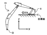
図1は、本実施の形態に係る建設機械の一例である油圧ショベルの外観を模式的に示す図である。 FIG. 1 is a diagram schematically showing the appearance of a hydraulic excavator, which is an example of a construction machine according to the present embodiment.
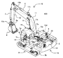
図1において、油圧ショベル600は、垂直方向にそれぞれ回動する複数の被駆動部材(ブーム11、アーム12、バケット(作業具)8)を連結して構成された多関節型のフロント装置(フロント作業機)15と、車体を構成する上部旋回体10及び下部走行体9とを備え、上部旋回体10は下部走行体9に対して旋回可能に設けられている。また、フロント装置15のブーム11の基端は上部旋回体10の前部に垂直方向に回動可能に支持されており、アーム12の一端はブーム11の基端とは異なる端部(先端)に垂直方向に回動可能に支持されており、アーム12の他端にはバケットリンク8aを介してバケット8が垂直方向に回動可能に支持されている。ブーム11、アーム12、バケット8、上部旋回体10、及び下部走行体9は、油圧アクチュエータであるブームシリンダ5、アームシリンダ6、バケットシリンダ7、旋回油圧モータ4、及び左右の走行油圧モータ3b(ただし、一方の走行油圧モータのみ図示)によりそれぞれ駆動される。
In FIG. 1, the
ブーム11、アーム12、及びバケット8は、フロント装置15を含む平面上で動作し、以下ではこの平面を動作平面と称することがある。つまり動作平面とは、ブーム11、アーム12、及びバケット8の回動軸に直交する平面であり、ブーム11、アーム12、及びバケット8の幅方向の中心に設定することができる。
The
オペレータが搭乗する運転室16には、フロント装置15の油圧アクチュエータ5〜7、及び上部旋回体10の旋回油圧モータ4を操作するための操作信号を出力する操作レバー(操作装置)である右操作レバー装置1c及び左操作レバー装置1dと、下部走行体9の左右の走行油圧モータ3bを操作するための操作信号を出力する走行用右操作レバー装置1a及び走行用左操作レバー装置1bとが設けられている。
Right operation, which is an operation lever (operation device) that outputs an operation signal for operating the hydraulic actuators 5 to 7 of the
操作レバー1c,1dはそれぞれ前後左右に傾倒可能であり、操作信号であるレバーの傾倒量、すなわちレバー操作量を電気的に検知する図示しない検出装置を含み、検出装置が検出したレバー操作量を制御装置の一部を構成する情報処理装置100(図2参照)に電気配線を介して出力する。つまり、操作レバー1c,1dの前後方向または左右方向に、油圧アクチュエータ4〜7の操作がそれぞれ割り当てられている。 The operating levers 1c and 1d can be tilted back and forth and left and right, respectively, and include a detection device (not shown) that electrically detects the tilting amount of the lever, which is an operation signal, that is, the lever operating amount. Output is performed via electrical wiring to the information processing device 100 (see FIG. 2) that constitutes a part of the control device. That is, the operations of the hydraulic actuators 4 to 7 are assigned to the operation levers 1c and 1d in the front-rear direction or the left-right direction, respectively.
ブームシリンダ5、アームシリンダ6、バケットシリンダ7、旋回油圧モータ4、及び左右の走行油圧モータ3bの動作制御は、エンジンや電動モータなどの原動機(本実施の形態では、エンジン14)によって駆動される油圧ポンプ装置2から各油圧アクチュエータ3b,4〜7に供給される作動油の方向及び流量をコントロールバルブ20で制御することにより行う。コントロールバルブ20は、図示しないパイロットポンプから電磁比例弁を介して出力される駆動信号(パイロット圧)により行われる。操作レバー1c,1dからの操作信号に基づいて制御装置で電磁比例弁を制御することにより、各油圧アクチュエータ3b,4〜7の動作が制御される。ブーム11はブームシリンダ5の伸縮により上部旋回体10に対して上下方向に回動され、アーム12はアームシリンダ6の伸縮によりブーム11に対して上下及び前後方向に回動され、バケット8はバケットシリンダ7の伸縮によりアーム12に対して上下及び前後方向に回動される。
The operation control of the boom cylinder 5, arm cylinder 6, bucket cylinder 7, swivel hydraulic motor 4, and left and right traveling
なお、操作レバー1c,1dは油圧パイロット方式であってもよく、それぞれオペレータにより操作される操作レバー1c,1dの操作方向及び操作量に応じたパイロット圧をコントロールバルブ20に駆動信号として供給し、各油圧アクチュエータ3b,4〜7を駆動するように構成しても良い。
The operation levers 1c and 1d may be of the hydraulic pilot system, and the pilot pressure corresponding to the operation direction and the operation amount of the operation levers 1c and 1d operated by the operator is supplied to the
ブームシリンダ5には、ブームシリンダ5のボトム側圧力を検出するブームボトム圧力センサ17aと、ブームシリンダ5のロッド側圧力を検出するブームロッド圧力センサ17bとが備えられている。また、アームシリンダ6には、アームシリンダ6のボトム側圧力を検出するアームボトム圧力センサ17cが備えられている。なお、本実施の形態では、ブームシリンダ5及びアームシリンダ6に圧力センサ17a〜17cを備える場合を例示しているが、例えば、コントロールバルブ20、或いは、コントロールバルブ20と各油圧アクチュエータ5,6を繋ぐ配管の途中に圧力センサを設けるように構成しても良い。
The boom cylinder 5 is provided with a boom
ブーム11の上部旋回体10との連結部近傍と、アーム12のブーム11との連結部近傍と、バケットリンク8aと、上部旋回体10とには、それぞれ、姿勢センサとして慣性計測装置(IMU: Inertial Measurement Unit)13a〜13dが配置されている。慣性計測装置13aは水平面に対するブーム11の角度(ブーム角度)を検出するブーム姿勢センサであり、慣性計測装置13bは水平面に対するアーム12の角度(アーム角度)を検出するアーム姿勢センサであり、慣性計測装置13cは水平面に対するバケットリンク8aの角度を検出するバケット姿勢センサである。また、慣性計測装置13dは、水平面に対する上部旋回体10の傾斜角度(ロール角、ピッチ角)を検出する車体姿勢センサである。
An inertial measurement unit (IMU:) is used as an attitude sensor in the vicinity of the connection portion of the
慣性計測装置13a〜13dは、角速度及び加速度を計測するものである。慣性計測装置13a〜13dが配置された上部旋回体10や各被駆動部材8,11,12が静止している場合を考えると、各慣性計測装置13a〜13dに設定されたIMU座標系における重力加速度の方向(つまり、鉛直下向き方向)と、各慣性計測装置13a〜13dの取り付け状態(つまり、各慣性計測装置13a〜13dと上部旋回体10や各被駆動部材8,11,12との相対的な位置関係)とに基づいて、上部旋回体10や各被駆動部材8,11,12の水平面に対する角度を検出することができる。ここで、慣性計測装置13a〜13cは、ブーム11、アーム12、及びバケット(作業具)8のそれぞれの姿勢情報(角度信号)を検出する姿勢情報検出装置を構成している。
The
なお、姿勢情報検出部は慣性計測装置に限られるものではなく、例えば、傾斜角センサを用いても良い。また、各被駆動部材8,11,12の連結部分にポテンショメータを配置し、上部旋回体10や各被駆動部材8,11,12の相対的な向き(姿勢情報)を検出し、検出結果から各被駆動部材8,11,12の姿勢(水平面に対する角度)を求めても良い。また、ブームシリンダ5、アームシリンダ6、及びバケットシリンダ7にそれぞれストロークセンサを配置し、ストローク変化量から上部旋回体10や各被駆動部材8,11,12の各接続部分における相対的な向き(姿勢情報)を算出し、その結果から各被駆動部材8,11,12の姿勢(水平面に対する角度)を求めるように構成しても良い。
The posture information detection unit is not limited to the inertial measurement unit, and for example, an inclination angle sensor may be used. Further, a potentiometer is arranged at the connecting portion of each of the driven
図2は、油圧ショベルに搭載される操作支援システムを概略的に示す図であり、図3は情報処理装置の詳細を示す機能ブロック図である。 FIG. 2 is a diagram schematically showing an operation support system mounted on a hydraulic excavator, and FIG. 3 is a functional block diagram showing details of an information processing device.
図2において、油圧ショベル600に搭載される操作支援システム500は、油圧ショベル600の動作を制御するための種々の機能を有する制御装置の一部を構成し、オペレータの掘削作業を支援するための情報(支援情報)を生成する情報処理装置100と、運転室16に配置されてオペレータに掘削作業の支援情報などを教示する液晶パネルなどの教示装置(表示装置)200とを有している。情報処理装置100には、左右の操作レバー装置1c,1dからの操作信号と、各慣性計測装置13a〜13dからの検出信号(角度信号:姿勢情報)と、設計面情報入力装置18からの設計面情報とが入力されており、これらの入力に基づいて情報処理を行っている。
In FIG. 2, the
設計面情報入力装置18は、複数の目標面(線分)が連なって設定された掘削対象の目標形状の情報(目標形状情報)である設計面情報を情報処理装置100に入力するものである。設計面情報入力装置18は、例えば記憶装置であり、作業機械の位置情報と掘削対象の目標形状(例えば法面形状)の3次元形状をポリゴンで定義した3次元施工図面とを用いて演算された目標形状情報が記憶されている。
The design surface information input device 18 inputs the design surface information, which is the target shape information (target shape information) of the excavation target set by connecting a plurality of target surfaces (line segments), to the
なお、情報処理装置100は、例えば、図示しないCPU(Central Processing Unit)と、CPUによる処理を実行するための各種プログラムを格納するROM(Read Only Memory)やHDD(Hard Disc Drive)などの記憶装置と、CPUがプログラムを実行する際の作業領域となるRAM(Random Access Memory)とを含むハードウェアを用いて構成されている。
The
図3において、情報処理装置100は、作業点位置演算部110、目標面設定部120、目標面距離演算部130、主操作判定部140、及び推奨操作演算部150を有している。
In FIG. 3, the
作業点位置演算部110は、慣性計測装置13a〜13dからの角度信号(姿勢情報)に基づいて、バケット(作業具)8上に設定された作業点の車体(上部旋回体10)に対する相対位置を演算し、作業点位置として教示装置200に送信するとともに、目標面設定部120と目標面距離演算部130へ出力する。ここで、バケット(作業具)8上に設定する作業点は、例えば、バケット8のつめ先中心とする。なお、作業点位置を表す座標系としては、ブーム11の回動中心を原点Oとして車体に固定し、上部旋回体10の前方にx軸、上方にz軸を設定したフロント座標系を用いる。
The work point
目標面設定部120は、作業点位置演算部110で演算された作業点位置に基づいて、設計面情報入力装置18から入力される設計面情報から作業対象となる目標面を抽出し、教示装置200に送信するとともに、目標面距離演算部130と主操作判定部140へ出力する。なお、設計面情報からの目標面の抽出には種々の方法が適用できるが、例えば、作業点に対して鉛直下方にある設計面を目標面としてもよい。また、作業点の鉛直下方に設計面が存在しない場合は、作業点に対して前方あるいは後方にある設計面を目標面としてもよい。
The target
図4は、目標面と車体との位置関係を模式的に示す側面図である。なお、図4においては図示の簡単のために油圧アクチュエータ5〜7の図示を省略している。 FIG. 4 is a side view schematically showing the positional relationship between the target surface and the vehicle body. In FIG. 4, the hydraulic actuators 5 to 7 are not shown for the sake of simplicity.
図4に示すように、フロント座標系において、目標面設定部120で設定される目標面の車体前方を基準とした目標面の傾き、すなわち、目標面のx軸とのなす角を目標面角度と定義する。また、目標面のブーム11の回動中心からの垂直距離、すなわち、目標面とフロント座標系の原点Oの距離を目標面高さと定義する。例えば、フロント座標系のx軸に平行で原点Oと同じ高さに上向きに設定された目標面例を考えると、目標面角度および目標面高さはそれぞれ0(ゼロ)になる。また、目標面例よりも車体前方側(x軸正側)が下がるような傾斜の目標面では目標面角度が正になり、目標面例よりも車体前方側が上がるような傾斜の目標面では目標面角度が負になる。また、また、目標面例よりも上方にある目標面(つまり、フロント座標系の原点Oが目標面の表面側に無い場合)では目標面高さが正になり、目標面例よりも下方にある目標面(つまり、フロント座標系の原点Oが目標面の表面側にある場合)では目標面高さが負になる。
As shown in FIG. 4, in the front coordinate system, the inclination of the target surface with respect to the front of the vehicle body of the target surface set by the target
目標面距離演算部130は、目標面設定部120で設定された目標面から作業点位置演算部110で演算された作業点位置までの距離である目標面距離を演算し、教示装置200に送信するとともに、推奨操作演算部150へ出力する。
The target surface
主操作判定部140は、目標面設定部120で設定された目標面に対してフロント装置15で掘削作業を行う場合に、ブーム11とアーム12のいずれの操作が主たる操作である主操作となるかを判定するものである。主操作判定部140は、目標面設定部120で設定された目標面の目標面角度と目標面高さとに応じて主操作を判定し、主操作判定として推奨操作演算部150へ出力する。
When the
ここで、掘削作業における主たる操作(主操作)とは、フロント装置15を動作させる場合の動作方向の主成分となる動きをする被駆動部材(本実施の形態ではブーム11又はアーム12)に該当する操作のことである。つまり、ある目標面に沿って作業点を移動させるように掘削作業を行う場合に、ブーム11又はアーム12のうち動作速度や動作量が大きい方を主操作とする。この主操作は、作業点の位置や移動方向によってブーム11又はアーム12いずれの操作が該当するかは異なるが、目標面(目標面角度および目標面高さ)が決まれば、その目標面に対する掘削作業における主操作も一意に決まる。
Here, the main operation (main operation) in the excavation work corresponds to a driven member (
例えば、第1の判定方法としては、作業点が目標面上を移動した場合の車体(上部旋回体10)に対するブーム11の角度変化量とブーム11に対するアーム12の角度変化量を公知の幾何学計算を用いて演算し、これらの比較に基づいて、角度変化量の大きい方の操作を主操作と判定する。また、第2の判定方法としては、作業点が目標面上にある状態でブーム11及びアーム12を回動駆動させた場合のブーム角速度に対する作業点の水平方向の速度成分と、アーム角速度に対する作業点の水平方向の速度成分とを演算し、これらの比較に基づいて、移動速度の大きい方の操作を主操作と判定してもよい。なお、図示しないが、本実施の形態では、目標面情報や姿勢情報などの情報に基づいて、掘削作業での目標面に対するバケット(作業具)8の姿勢が変わらないように制御する場合を示している。
For example, as a first determination method, a known geometry is used to determine the amount of change in the angle of the
図5は、目標面の目標面角度および目標面高さをそれぞれ変化させて主操作を判定した場合の判定結果を示す図である。 FIG. 5 is a diagram showing a determination result when the main operation is determined by changing the target surface angle and the target surface height of the target surface, respectively.
図5において、主操作の判定結果は、幾何学的に作業点が届かない位置であり掘削作業が出来ない領域(掘削不可領域)51,52と、ブーム11の角度変化量が比較的大きいためブーム11の操作を主操作として判定する領域(ブーム主操作領域)53と、アーム角速度に応じた作業点の水平方向の速度成分が比較的小さいためブーム11操作を主操作として判定する領域(ブーム主操作領域)54と、アーム12の操作を主操作として判定するその他の領域(アーム主操作領域55)と有している。ここで、図5は、目標面の目標面角度および目標面高さを入力とし、主操作の判定結果(主操作判定)を出力として与える主操作判定テーブルということができる。
In FIG. 5, the determination result of the main operation is that the work points are geometrically out of reach and the excavation work cannot be performed (excavation impossible areas) 51 and 52, and the amount of change in the angle of the
なお、図5では、第1及び第2の判定方法を例示して説明したが、他の判定方法を用いて主操作の判定を行ってもよい。また、図5では、第1及び第2の判定方法の両方を用いて主操作を判定した結果を合わせて一つの判定結果としたが、例えば、第2の判定方法のみを用いて主操作の判定結果(主操作判定テーブル)を設定してもよい。この場合には、図5に示した主操作の判定結果に対してブーム主操作領域54が無くなってアーム主操作領域となった判定結果が得られる。また、例えば、第1の判定方法のみを用いて主操作の判定結果(主操作判定テーブル)を設定した場合には、図5に示した主操作の判定結果に対してブーム主操作領域53の範囲が縮小された判定結果が得られる。また、主操作の判定結果(主操作判定テーブル)の各領域は、上部旋回体10やフロント装置15を構成する部材の構造や相対的な駆動可能範囲から幾何学的に決まるものであり、目標面の目標面角度や目標面高さの原点Oや、原点Oを通る各座標軸に対して対称であるとは限らない。
Although the first and second determination methods have been illustrated and described in FIG. 5, other determination methods may be used to determine the main operation. Further, in FIG. 5, the results of determining the main operation using both the first and second determination methods are combined into one determination result. For example, the main operation is performed using only the second determination method. The determination result (main operation determination table) may be set. In this case, the determination result that the boom
推奨操作演算部150は、目標面設定部120で設定された目標面(目標面角度)と、目標面距離演算部130で演算された目標面距離と、主操作判定部140の判定結果(主操作判定)と、操作レバー(操作装置)1c,1dからの操作信号とに基づいて、従操作に係る支援情報である従操作指示情報を演算し、教示装置(表示装置)200に出力する。従操作指示情報は、従操作の推奨値である従操作の推奨操作量および推奨操作方向、現在操作量(操作方向の情報を含む)などの情報を含んでいる。
The recommended
図6は、推奨操作演算部による従操作指示情報の演算処理を示すフローチャートである。 FIG. 6 is a flowchart showing a calculation process of the slave operation instruction information by the recommended operation calculation unit.
図6において、推奨操作演算部150は、まず、主操作と判定したフロント装置15の被駆動部材(ブーム11又はアーム12)の操作信号に基づいて主操作の被駆動部材の角速度(主操作角速度)を演算する(ステップS100)。例えば、ブーム11が主操作である場合は、ブーム操作信号に応じてブームシリンダ5の伸縮速度を演算し、ブーム角度信号に基づきブームシリンダの伸縮速度をブーム角速度に変換する。アームが主操作である場合も同様に、アーム操作信号に応じてアームシリンダ6の伸縮速度を演算し、アーム角度信号に基づきアームシリンダの伸縮速度をアーム角速度に変換する。なお、ブーム11及びアーム12の慣性計測装置13b,13cからの角度信号を微分することで主操作角速度を演算してもよい。
In FIG. 6, the recommended
続いて、目標面距離に基づいて目標面に対する垂直方向の目標速度である目標上下速度を演算する(ステップS110)。目標面距離が正の場合、すなわち作業点が目標面から離れている場合は目標上下速度を負とし、目標面距離が負の場合、すなわち作業点が目標面へ侵入している場合は目標上下速度を正とする。これにより、作業点が目標面に沿って動作するように目標上下速度が演算される。 Subsequently, the target vertical velocity, which is the target velocity in the direction perpendicular to the target surface, is calculated based on the target surface distance (step S110). If the target surface distance is positive, that is, if the work point is far from the target surface, the target vertical speed is negative, and if the target surface distance is negative, that is, if the work point is invading the target surface, the target vertical speed is negative. Let the speed be positive. As a result, the target vertical velocity is calculated so that the work point moves along the target surface.
続いて、主操作角速度と目標上下速度とに基づいて、角度信号に応じて従操作目標角速度を演算する(ステップS120)。例えば、ブーム11の操作が主操作である場合は、以下の式(1)を用いて従操作であるアーム12の目標角速度ω2tを演算する。
Subsequently, the secondary operation target angular velocity is calculated according to the angle signal based on the main operation angular velocity and the target vertical velocity (step S120). For example, when the operation of the

ここで、vztは目標上下速度であり、ω1はブーム角速度である。また、a21及びa22は公知のヤコビ行列の成分であって、目標角速度と角度信号とに基づいて演算されるものであり、それぞれ、ブーム角速度およびアーム角速度に応じた目標面上における作業点の垂直方向速度を演算するときの係数である。 Here, v zt is the target vertical velocity, and ω 1 is the boom angular velocity. Further, a 21 and a 22 are known Jacobian matrix components, which are calculated based on the target angular velocity and the angular signal, and are work points on the target surface according to the boom angular velocity and the arm angular velocity, respectively. It is a coefficient when calculating the vertical velocity of.
また、同様に、アーム12の操作が主操作である場合は、以下の式(2)を用いて従操作であるブーム11の目標角速度ω1tを演算する。
Similarly, when the operation of the
同様に、vztは目標上下速度であり、ω2はアーム角速度であり、a21及びa22は公知のヤコビ行列の成分である。 Similarly, v zt is the target vertical velocity, ω 2 is the arm angular velocity, and a 21 and a 22 are known Jacobian matrix components.
続いて、従操作の目標角速度に基づいて、従操作の推奨値である従操作量目標値(推奨操作量)及び推奨操作方向を演算する(ステップS130)。 Subsequently, based on the target angular velocity of the slave operation, the slave operation amount target value (recommended operation amount) and the recommended operation direction, which are the recommended values of the slave operation, are calculated (step S130).
続いて、主操作判定、操作信号、従操作量目標値に基づいて、従操作指示情報を生成し、教示装置200へ送信する(ステップS140)。従操作指示情報は従操作(ブーム11又はアーム12)の操作指示情報であり、ブーム11が主操作である場合は従操作のアーム12の推奨操作量および推奨操作方向を、アーム12が主操作である場合はブーム11の推奨操作量および推奨操作方向を従操作指示情報として送信する。
Subsequently, based on the main operation determination, the operation signal, and the slave operation amount target value, the slave operation instruction information is generated and transmitted to the teaching device 200 (step S140). The slave operation instruction information is the operation instruction information of the slave operation (
図7は、教示装置が配置される運転室内の様子を模式的に示す図である。また、図8は、教示装置の表示内容を示す図である。 FIG. 7 is a diagram schematically showing a state of the driver's cab in which the teaching device is arranged. Further, FIG. 8 is a diagram showing the display contents of the teaching device.
図7に示すように、運転室16には、オペレータが座る座席16aの前方左右にそれぞれ設けられた操作レバー(操作装置)である右操作レバー装置1c及び左操作レバー装置1dと、オペレータが車外を見る際に視界を妨げないように座席16a右側の右操作レバー装置1c前方に配置された教示装置200とが設置されている。図7では、右操作レバー装置1cの前後方向にブーム上げ操作及びブーム下げ操作が割り当てられ、左操作レバー装置1dの前後方向にアームダンプ操作及びアームクラウド操作が割り当てられている。なお、運転室16内に配置される走行用右操作レバー装置1a及び走行用左操作レバー装置1bを含む他の構成については図示及び説明を省略する。
As shown in FIG. 7, in the driver's
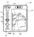
図8に示すように、教示装置200には、情報処理装置100で判定された従操作名を表示する従操作名表示部201と、従操作の推奨操作量、推奨操作方向、及び、現在操作量を示す従操作表示部202と、現在の目標面とフロント装置15の位置関係を表示する作業装置動作表示部203とが表示されている。図8では、フロント装置15の前方に対向する切り立った壁面を目標面として掘削作業を行う場合を例示している。この場合、アーム12が従操作であり、従操作名表示部201には従操作として「アーム」の表示がなされている。
As shown in FIG. 8, the
従操作表示部202は、従操作に対応する操作レバー1cの操作方向(つまり、前後方向)に対応して上下方向に延在する表示領域を有しており、表示領域に表示される図形の上下方向の位置や、表示領域に表示される図形の強調表示の有無などによって従操作の推奨操作量および推奨操作方向を示している。
The slave
従操作表示部202には、操作レバー1cが操作されていない状態であることを示す図形(非操作表示)202b(ここでは、円形の図形で例示する)が表示領域の上下方向のほぼ中央部に配置されている。また、従操作表示部202には、推奨操作量及び推奨操作方向を示す図形(推奨操作量表示)202a(ここでは、2つの三角形を伴う方形の図形で例示する)が表示領域の上下方向のいずれかの位置(図8では非操作表示202bの下側)に配置されている。また、従操作表示部202の表示領域の上下方向において、非操作表示(図形202b)及び推奨操作量表示(図形202a)以外の部分を補完するように、他の複数の図形202c(ここでは、図形202aの方向を指す矢印形状の図形で例示する)が配置されている。
On the slave
従操作表示部202においては、非操作表示(図形202b)から見て、操作レバー1dの前方向への操作(アームダンプ操作)に対応する上方向がアームダンプを、操作レバー1dの後方向への操作(アームクラウド操作)に対応する下方向がアームクラウドを示している。また、非操作表示(図形202b)からの上下方向の距離によって操作レバー1dの操作量を示している。従操作表示部202において、現在の操作レバー1dの操作量は、該当する操作量および操作方向の図形を他の図形よりも強調表示(現在操作量表示)することにより示す。また、従操作表示部202において、操作レバー1dの推奨操作量及び推奨操作方向は、非操作表示(図形202b)から見た推奨操作量表示(図形202a)の表示位置、すなわち、非操作表示(図形202b)からの距離および方向で示す。
In the slave
図8では、操作レバー1dの推奨操作方向がアームクラウド方向であって、推奨操作量が図形202bから図形202aの3個分の距離で表される操作量である場合を例示している。また、現在は操作レバー1dが操作されておらず、図形202bが他の図形よりも強調表示されている場合を例示している。
FIG. 8 illustrates a case where the recommended operation direction of the
なお、図8ではアーム12が従操作である場合を例示して説明したが、ブーム11が従操作である場合にも同様に表示される。すなわち、ブーム11が従操作である場合には、従操作名表示部201に従操作として「ブーム」の表示がなされ、操作レバー1cの前方向への操作(ブーム下げ操作)に対応する上方向がブーム下げを、操作レバー1cの後方向への操作(ブーム上げ操作)に対応する下方向がブーム上げを示すように非操作表示(図形202b)や推奨操作量表示(図形202a)、他の複数の図形202cなどが表示される。
In FIG. 8, the case where the
作業装置動作表示部203には、現在の目標面とフロント装置15の位置関係が表示されている。図8では、前述のように、フロント装置15の前方に対向するようにz軸に沿って設定された目標面の掘削作業を行う場合を例示している。なお、作業装置動作表示部203には現在の目標面とフロント装置15の位置関係のみが表示されるが、図8では説明のために目標面とフロント装置15の3つの位置関係を同時に示している。
The working device
例えば、図8の状態において、作業装置動作表示部203に示すフロント装置15の状態203aから状態203bを経て状態203cまでバケット8(作業点)が動作するように主操作であるブーム11を操作すると、従操作であるアーム12の推奨操作量表示(図形202a)の表示位置が図形202aの位置から図形202bの位置を経て図形202cの位置まで移動する。
For example, in the state of FIG. 8, when the
このように、従操作に対応する操作装置の操作方向に対応して延在する表示領域の表示を、従操作の推奨操作方向に対応して変化させることにより、従操作の推奨操作量及び推奨操作方向をオペレータに教示することができる。つまり、操作レバー1dの操作方向と教示装置200の表示内容の方向が一致しているので、オペレータは、教示装置200からの情報によって、作業点(つまり、作業具であるバケット8)を目標面に沿って動作させるための従操作の適切な推奨操作量および推奨操作方向を直感的に理解しやすくなり、また、主操作であるブーム11を操作するとともに、従操作表示部202の現在操作量表示(強調表示)が推奨操作量表示(図形202a)に一致するように従操作であるアーム12の操作を行うことで、作業点(つまり、作業具であるバケット8)を目標面に沿って容易に動作させることができる。
In this way, by changing the display of the display area extending corresponding to the operation direction of the operation device corresponding to the slave operation according to the recommended operation direction of the slave operation, the recommended operation amount and the recommended operation amount of the slave operation are recommended. The operation direction can be taught to the operator. That is, since the operation direction of the
以上のように構成した本実施の形態の効果を図18〜図21を参照しつつ説明する。 The effects of the present embodiment configured as described above will be described with reference to FIGS. 18 to 21.
図18〜図21は、目標面とフロント装置の種々の位置関係をそれぞれ例示する図である。なお、図18〜図21においては、車体9,10や油圧アクチュエータ5〜7の図示を省略する。
18 to 21 are diagrams illustrating various positional relationships between the target surface and the front device, respectively. In FIGS. 18 to 21, the
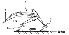
例えば、図18に示すように、油圧ショベルのブームやアーム、バケット等によって構成されるフロント装置よりも十分下方の地形を水平な目標地形に施工する作業(いわゆる、水平引き作業)において、オペレータは、アームの操作によって設計面に平行な方向の掘削速度を調節し、ブームの操作によって掘削高さを調整する。このような場合、オペレータは、上記従来技術で教示されるようなバケットの最近接位置と設計面との間の距離を示す情報(以降、距離情報を称する)を参照することによってブームの操作を適切に行うことができる。 For example, as shown in FIG. 18, in the work of constructing a terrain sufficiently below the front device composed of a boom, arm, bucket, etc. of a hydraulic excavator on a horizontal target terrain (so-called horizontal pulling work), the operator , The excavation speed in the direction parallel to the design surface is adjusted by operating the arm, and the excavation height is adjusted by operating the boom. In such a case, the operator operates the boom by referring to information indicating the distance between the closest position of the bucket and the design surface (hereinafter referred to as distance information) as taught in the prior art. Can be done properly.
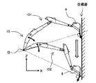
しかしながら、フロント装置に対する設計面の位置によっては、距離情報だけではオペレータによる適切な操作が困難な場合がある。すなわち、例えば、図19に示すように、目標地形として切り立った壁面を掘削するような場合、バケットを設計面に沿って上方から下方に移動させると、ブーム支点の高さを境にアームに必要な動作方向(目標面の高さ方向の速度)が逆転してしまう。具体的には、図19におけるフロント装置15の姿勢151のようにバケット8がフロント座標系の原点Oよりも高い位置に有る場合にブーム下げ動作を行いながらアームクラウド動作を行うとバケット8が目標地形に沿って移動するが、姿勢152のようにバケット8がフロント座標系の原点Oよりも低い位置に有る場合にブーム下げ動作を行いながらアームクラウド動作を行うとバケット8が目標地形から離脱してしまう。つまり、オペレータによるアームの操作方向が逆転してしまうため、距離情報だけでは適切な操作を行うことが困難である。
However, depending on the position of the design surface with respect to the front device, it may be difficult for the operator to perform an appropriate operation based on the distance information alone. That is, for example, as shown in FIG. 19, when excavating a steep wall surface as a target terrain, if the bucket is moved from above to below along the design surface, it is necessary for the arm at the height of the boom fulcrum as a boundary. The operating direction (speed in the height direction of the target surface) is reversed. Specifically, when the
また、図20に示すように、フロント装置15よりも高所の水平引き作業、或いは、図21に示すように、下方手前側の壁面を目標地形とする掘削作業を行うような場合には、掘削高さを調節するためブームの操作によってアームに必要な掘削速度が大きく変化してしまう。つまり、オペレータはブームの操作によって生じるアームに必要な速度の変化に対応しなければならず、この場合にも距離情報だけで十分な掘削精度を得ることは困難であった。
Further, as shown in FIG. 20, when the horizontal pulling work at a place higher than the
これに対して本実施の形態においては、ブーム11、アーム12、及びバケット(作業具)8を垂直方向に回動可能に連結して構成され、油圧ショベル600(建設機械)の車体(上部旋回体10、下部走行体9)に垂直方向に回動可能に支持された多関節型のフロント装置15と、フロント装置15のブーム11、アーム12、及びバケット8をそれぞれ操作するための操作信号を出力する操作レバー(操作装置)1c,1dと、ブーム11、アーム12、及びバケット8のそれぞれの姿勢情報を検出する慣性計測装置13a〜13c(姿勢情報検出装置)と、慣性計測装置13a〜13cの検出情報と、掘削対象の目標形状の情報である設計面情報と、操作レバー1c,1dからの操作信号とに基づいて情報処理を行う情報処理装置100とを備えた油圧ショベル600において、情報処理装置100は、姿勢情報に基づいてバケット8上に設定された作業点の車体9,10に対する相対位置を演算する作業点位置演算部110と、設計面情報に基づいて掘削作業の対象となる目標面を設定する目標面設定部120と、目標面に沿って作業点を移動させる場合にブーム11及びアーム12のいずれの操作が主たる操作である主操作であるかを判定する主操作判定部140と、掘削作業を行う場合に、ブーム11及びアーム12の操作のうち主操作とは異なる他の操作である従操作の推奨操作量及び推奨操作方向を主操作の操作量及び操作方向に応じて演算し、従操作の推奨操作量及び推奨操作方向を教示装置(表示装置)200に表示する推奨操作演算部150とを備えて構成したので、オペレータに適切な操作を分かりやすく伝えることができる。
On the other hand, in the present embodiment, the
<第2の実施の形態>
本発明の第2の実施の形態を図9及び図10を参照しつつ説明する。
<Second embodiment>
A second embodiment of the present invention will be described with reference to FIGS. 9 and 10.
本実施の形態は、教示装置に従操作指示情報(従操作の推奨操作量、推奨操作方向、及び現在操作量)と併せて主操作指示情報(主操作の現在操作量及び推奨操作方向)を表示するものである。 In this embodiment, the main operation instruction information (current operation amount and recommended operation direction of the main operation) is provided together with the follow operation instruction information (recommended operation amount, recommended operation direction, and current operation amount of the follow operation) of the teaching device. It is to be displayed.
図9は、情報処理装置の詳細を示す機能ブロック図である。また、図10は、教示装置の表示内容を示す図である。図中、第1の実施の形態と同様の部材には同じ符号を付し、説明を省略する。 FIG. 9 is a functional block diagram showing details of the information processing apparatus. Further, FIG. 10 is a diagram showing the display contents of the teaching device. In the figure, the same members as those in the first embodiment are designated by the same reference numerals, and the description thereof will be omitted.
図9において、情報処理装置100Aは、作業点位置演算部110、目標面設定部120、目標面距離演算部130、主操作判定部140、及び推奨操作演算部150Aを有している。
In FIG. 9, the
推奨操作演算部150Aは、目標面設定部120で設定された目標面(目標面角度)と、目標面距離演算部130で演算された目標面距離と、主操作判定部140の判定結果(主操作判定)と、操作レバー(操作装置)1c,1dからの操作信号とに基づいて、第1及び第2操作指示情報(従操作指示情報又は主操作指示情報)を演算し、教示装置200に送信する。
The recommended
第1操作指示情報はブーム操作に関する操作指示情報であり、第2操作指示情報はアーム操作に関する操作指示情報である。つまり、ブーム11の操作が主操作である場合には、第1操作指示情報として主操作指示情報(主操作の現在操作量及び推奨操作方向)を生成して送信し、第2操作指示情報として従操作指示情報(従操作の推奨操作量及び推奨操作方向)を生成して送信する。また、アーム12の操作が主操作である場合には、第1操作指示情報として従操作指示情報を生成して送信し、第2操作指示情報として主操作指示情報を生成して送信する。
The first operation instruction information is the operation instruction information related to the boom operation, and the second operation instruction information is the operation instruction information related to the arm operation. That is, when the operation of the
図10に示すように、教示装置200には、情報処理装置100で判定された従操作名を表示する従操作名表示部201と、従操作の推奨操作量、推奨操作方向、及び、現在操作量を示す従操作表示部202と、情報処理装置100Aで判定された主操作名を表示する主操作名表示部204と、主操作の現在の操作量および操作方向を示す主操作表示部205と、現在の目標面とフロント装置15の位置関係を表示する作業装置動作表示部203とが表示されている。図8では、フロント装置15の前方に対向する切り立った壁面を目標面として掘削作業を行う場合を例示している。この場合、アーム12が従操作でありブーム11が主操作であるので、従操作名表示部201には従操作として「アーム」の表示がなされ、主操作名表示部204には主操作として「ブーム」の表示がなされている。
As shown in FIG. 10, the
主操作表示部205は、主操作に対応する操作レバー1cの操作方向(つまり、前後方向)に対応して上下方向に延在する表示領域を有しており、表示領域に表示される図形の形状や、表示領域に表示される図形の強調表示の有無などによって主操作の現在操作量および推奨操作方向を示している。
The main
主操作表示部205には、操作レバー1cが操作されていない状態であることを示す図形(非操作表示)205a(ここでは、円形の図形で例示する)が表示領域の上下方向のほぼ中央部に配置されている。また、主操作表示部205には、操作レバー1cの推奨操作方向を示す複数の図形(推奨操作方向表示)205b(推奨操作方向を指す矢印形状の図形で例示する)が図形(非操作表示)205aの上下方向のいずれか(図10では非操作表示205aの上側)に並べて配置されている。また、主操作表示部205の表示領域の上下方向において、非操作表示(図形205a)及び推奨操作方向表示(図形205b)以外の部分を補完するように、他の複数の図形205c(ここでは、方形の図形で例示する)が配置されている。
In the main
主操作表示部205においては、非操作表示(図形205a)から見て、操作レバー1cの前方向への操作(ブーム下げ操作)に対応する上方向がブーム下げを、操作レバー1cの後方向への操作(ブーム上げ操作)に対応する下方向がブーム上げを示している。また、非操作表示(図形205a)からの上下方向の距離によって操作レバー1cの操作量を示している。主操作表示部205において、現在の操作レバー1cの操作量は、該当する操作量および操作方向の図形を他の図形よりも強調表示(現在操作量表示)することにより示す。また、主操作表示部205において、操作レバー1cの推奨操作方向は、非操作表示(図形205a)から見た推奨操作方向表示(図形205b)の表示方向で示す。図8では、操作レバー1cの推奨操作方向がブーム下げ方向であって、現在操作量が図形205aから図形205bの3個分の距離で表される操作量である場合を例示している。
In the main
その他の構成は第1の実施の形態と同様である。 Other configurations are the same as in the first embodiment.
以上のように構成した本実施の形態においても第1の実施の形態と同様の効果を得ることができる。 Also in the present embodiment configured as described above, the same effect as that of the first embodiment can be obtained.
また、教示装置200に従操作指示情報(従操作の推奨操作量、推奨操作方向、及び現在操作量)と併せて主操作指示情報(主操作の現在操作量及び推奨操作方向)を表示するように構成したので、オペレータにどの操作から行うべきかを分かり易く伝えることができる。
In addition, the main operation instruction information (current operation amount and recommended operation direction of the main operation) is displayed together with the operation instruction information (recommended operation amount, recommended operation direction, and current operation amount of the slave operation) of the
<第3の実施の形態>
本発明の第3の実施の形態を図11〜図13を参照しつつ説明する。
<Third embodiment>
A third embodiment of the present invention will be described with reference to FIGS. 11 to 13.
本実施の形態は、第2の実施の形態において教示装置とは別に補助教示装置を備え、情報処理装置で演算された第1及び第2操作指示情報(従操作指示情報又は主操作指示情報)を、教示装置と補助教示装置に分けて送信するものである。 In the second embodiment, the second embodiment is provided with an auxiliary teaching device in addition to the teaching device, and the first and second operation instruction information calculated by the information processing device (secondary operation instruction information or main operation instruction information). Is transmitted separately to the teaching device and the auxiliary teaching device.
図11は、油圧ショベルに搭載される操作支援システムを概略的に示す図である。図中、第1及び第2の実施の形態と同様の部材には同じ符号を付し、説明を省略する。 FIG. 11 is a diagram schematically showing an operation support system mounted on a hydraulic excavator. In the figure, the same members as those in the first and second embodiments are designated by the same reference numerals, and the description thereof will be omitted.
図11において、操作支援システム500Bは、油圧ショベル600の動作を制御するための種々の機能を有する制御装置の一部を構成し、オペレータの掘削作業を支援するための情報(支援情報)を生成する情報処理装置100Aと、運転室16に配置されてオペレータに掘削作業の支援情報などを教示する液晶パネルなどの教示装置(表示装置)200及び補助教示装置(表示装置)300とを有している。情報処理装置100Aには、左右の操作レバー装置1c,1dからの操作信号と、各慣性計測装置13a〜13dからの検出信号(角度信号:姿勢情報)と、設計面情報入力装置18からの設計面情報とが入力されており、これらの入力に基づいて情報処理を行っている。
In FIG. 11, the operation support system 500B constitutes a part of a control device having various functions for controlling the operation of the
情報処理装置100Aは、ブーム操作に関する操作指示情報である第1操作指示情報(従操作指示情報又は主操作指示情報)を演算して教示装置200に送信するとともに、アーム操作に関する操作指示情報である第2操作指示情報(従操作指示情報又は主操作指示情報)を演算して補助教示装置300に送信する。つまり、ブーム11の操作が主操作である場合には、第1操作指示情報として主操作指示情報(主操作の現在操作量及び推奨操作方向)を生成して送信し、第2操作指示情報として従操作指示情報(従操作の推奨操作量、推奨操作方向、及び現在操作量)を生成して送信する。また、アーム12の操作が主操作である場合には、第1操作指示情報として従操作指示情報を生成して送信し、第2操作指示情報として主操作指示情報を生成して送信する。
The
図12は、教示装置及び補助教示装置が配置される運転室内の様子を模式的に示す図である。また、図13は、教示装置及び補助教示装置の表示内容を比較のために並べて示す図である。 FIG. 12 is a diagram schematically showing a state of the driver's cab in which the teaching device and the auxiliary teaching device are arranged. Further, FIG. 13 is a diagram showing the display contents of the teaching device and the auxiliary teaching device side by side for comparison.
図12に示すように、運転室16には、オペレータが座る座席16aの前方左右にそれぞれ設けられた操作レバー(操作装置)である右操作レバー装置1c及び左操作レバー装置1dと、オペレータが車外を見る際に視界を妨げないように座席16a右側の右操作レバー装置1c前方に配置された教示装置200と、同様にオペレータが車外を見る際に視界を妨げないように座席16a左側の左操作レバー装置1d前方に配置された補助教示装置300とが設置されている。なお、補助教示装置300は、例えばスマートフォンなどの携帯端末でもよく、補助教示装置ホルダ301に設置される。
As shown in FIG. 12, in the driver's
図12では、右操作レバー装置1cの前後方向にブーム上げ操作及びブーム下げ操作が割り当てられ、左操作レバー装置1dの前後方向にアームダンプ操作及びアームクラウド操作が割り当てられている。なお、運転室16内に配置される走行用右操作レバー装置1a及び走行用左操作レバー装置1bを含む他の構成については図示及び説明を省略する。
In FIG. 12, a boom raising operation and a boom lowering operation are assigned in the front-rear direction of the right
図13に示すように、ブーム操作に対応する右操作レバー装置1c前方に配置された教示装置200にはブーム操作に関する第1操作指示情報に基づいた表示がなされ、アーム操作に対応する左操作レバー装置1d前方に配置された補助教示装置300にはアーム操作に関する第2操作指示情報に基づいた表示がなされる。図13では、フロント装置15の前方に対向する切り立った壁面を目標面として掘削作業を行う場合を例示している。この場合、アーム12が従操作でありブーム11が主操作であるので、教示装置200には情報処理装置100Aで第1操作指示情報として生成された従操作指示情報に基づいた表示がなされ、補助教示装置300には第2操作指示情報として生成された主操作指示情報に基づいた表示がなされる。
As shown in FIG. 13, the
つまり、アーム12が従操作でありブーム11が主操作であるので、教示装置200には、情報処理装置100Aで判定された主操作名を表示する主操作名表示部204と、主操作の現在の操作量および操作方向を示す主操作表示部205と、現在の目標面とフロント装置15の位置関係を表示する作業装置動作表示部203とが表示される。また、補助教示装置300には、情報処理装置100Aで判定された従操作名を表示する従操作名表示部201と、従操作の推奨操作量、推奨操作方向、及び、現在操作量を示す従操作表示部202とが表示される。補助教示装置300の従操作名表示部201には従操作として「アーム」の表示がなされ、教示装置200の主操作名表示部204には主操作として「ブーム」の表示がなされている。
That is, since the
その他の構成は第2の実施の形態と同様である。 Other configurations are the same as in the second embodiment.
以上のように構成した本実施の形態においても第2の実施の形態と同様の効果を得ることができる。 The same effect as that of the second embodiment can be obtained in the present embodiment configured as described above.
また、教示装置200と補助教示装置300をそれぞれ表示対象とする操作量に対応した操作レバー1c,1dの近くに配置するように構成したので、オペレータがより直感的に適切な操作を理解しやすくなる。
Further, since the
<第4の実施の形態>
本発明の第4の実施の形態を図14及び図15を参照しつつ説明する。
<Fourth Embodiment>
A fourth embodiment of the present invention will be described with reference to FIGS. 14 and 15.
本実施の形態は、第3の実施の形態において操作レバーのパターンが変更された場合に対応した表示を行うようにしたものである。 In the present embodiment, the display corresponding to the case where the pattern of the operation lever is changed in the third embodiment is performed.
図14は、教示装置及び補助教示装置が配置される運転室内の様子を模式的に示す図である。また、図15は、補助教示装置の表示内容を示す図である。図中、第1〜第3の実施の形態と同様の部材には同じ符号を付し、説明を省略する。 FIG. 14 is a diagram schematically showing a state of the driver's cab in which the teaching device and the auxiliary teaching device are arranged. Further, FIG. 15 is a diagram showing the display contents of the auxiliary teaching device. In the figure, the same members as those in the first to third embodiments are designated by the same reference numerals, and the description thereof will be omitted.
図14に示すように、運転室16には、オペレータが座る座席16aの前方左右にそれぞれ設けられた操作レバー(操作装置)である右操作レバー装置1c及び左操作レバー装置1dと、オペレータが車外を見る際に視界を妨げないように座席16a右側の右操作レバー装置1c前方に配置された教示装置200と、同様にオペレータが車外を見る際に視界を妨げないように座席16a左側の左操作レバー装置1d前方に配置された補助教示装置300Cとが設置されている。
As shown in FIG. 14, in the driver's
図14では、右操作レバー装置1cの前後方向にブーム上げ操作及びブーム下げ操作が割り当てられ、左操作レバー装置1dの左右方向にアームダンプ操作及びアームクラウド操作が割り当てられている。なお、運転室16内に配置される走行用右操作レバー装置1a及び走行用左操作レバー装置1bを含む他の構成については図示及び説明を省略する。
In FIG. 14, a boom raising operation and a boom lowering operation are assigned in the front-rear direction of the right
図15に示すように、アーム操作に対応する左操作レバー装置1d前方に配置された補助教示装置300Cには、アーム操作に関する第2操作指示情報に基づいた表示がなされる。図15では、アーム12が従操作であり、補助教示装置300には、第2操作指示情報として生成された主操作指示情報に基づいた表示がなされる場合を例示する。この場合、補助教示装置300Cには、情報処理装置100Aで判定された従操作名を表示する従操作名表示部201と、従操作の推奨操作量、推奨操作方向、及び、現在操作量を示す従操作表示部202Cとが表示される。補助教示装置300Cの従操作名表示部201には従操作として「アーム」の表示がなされる。
As shown in FIG. 15, the
従操作表示部202Cは、従操作に対応する操作レバー1dの操作方向(つまり、左右方向)に対応して左右方向に延在する表示領域を有しており、表示領域に表示される図形の形状や、表示領域に表示される図形の強調表示の有無などによって従操作の現在操作量および推奨操作方向を示している。
The slave
従操作表示部202Cには、操作レバー1dが操作されていない状態であることを示す図形(非操作表示)202b(ここでは、円形の図形で例示する)が表示領域の左右方向のほぼ中央部に配置されている。また、従操作表示部202Cには、推奨操作量及び推奨操作方向を示す図形(推奨操作量表示)202a(ここでは、2つの三角形を伴う方形の図形で例示する)が表示領域の左右方向のいずれかの位置(図8では非操作表示202bの右側)に配置されている。また、従操作表示部202Cの表示領域の左右方向において、非操作表示(図形202b)及び推奨操作量表示(図形202a)以外の部分を補完するように、他の複数の図形202c(ここでは、図形202aの方向を指す矢印形状の図形で例示する)が配置されている。
On the slave
その他の構成は第3の実施の形態と同様である。 Other configurations are the same as those in the third embodiment.
以上のように構成した本実施の形態においても第3の実施の形態と同様の効果を得ることができる。 The same effect as that of the third embodiment can be obtained in the present embodiment configured as described above.
また、操作レバーのパターンが変更された場合においても、その操作レバーに対応する補助教示装置300(または、教示装置200)を変更後の操作レバーのパターンに合わせた方向(例えば横方向)に向けて設置するように構成したので、操作レバーの方向と補助教示装置300(または、教示装置200)の表示内容の方向が一致するため、オペレータがより直感的に適切な操作を理解しやすくなる。 Further, even when the pattern of the operating lever is changed, the auxiliary teaching device 300 (or the teaching device 200) corresponding to the operating lever is directed in a direction (for example, a lateral direction) that matches the pattern of the operating lever after the change. Since the direction of the operation lever and the direction of the display content of the auxiliary teaching device 300 (or the teaching device 200) are the same, the operator can more intuitively understand the appropriate operation.
<第5の実施の形態>
本発明の第5の実施の形態を図16及び図17を参照しつつ説明する。
<Fifth Embodiment>
A fifth embodiment of the present invention will be described with reference to FIGS. 16 and 17.
本実施の形態は、第2の実施の形態において主操作の操作量及び操作方向に基づいて演算及び表示されていた従操作の推奨操作量及び推奨操作方向を、オペレータによるレバー操作がなされていない場合にも予測的に演算及び表示するようにしたものである。 In the present embodiment, the operator does not operate the lever for the recommended operation amount and the recommended operation direction of the slave operation calculated and displayed based on the operation amount and the operation direction of the main operation in the second embodiment. Even in the case, it is calculated and displayed predictively.
図16は、情報処理装置の詳細を示す機能ブロック図である。図中、第1及び第2の実施の形態と同様の部材には同じ符号を付し、説明を省略する。 FIG. 16 is a functional block diagram showing details of the information processing apparatus. In the figure, the same members as those in the first and second embodiments are designated by the same reference numerals, and the description thereof will be omitted.
図16において、情報処理装置100Dは、作業点位置演算部110、目標面設定部120、目標面距離演算部130、主操作判定部140、推奨操作演算部150D、及び加算演算子170を有している。
In FIG. 16, the
推奨操作演算部150Dは、目標面設定部120で設定された目標面(目標面角度)と、目標面距離演算部130で演算された目標面距離と、主操作判定部140の判定結果(主操作判定)と、操作レバー(操作装置)1c,1dからの操作信号とに基づいて、第1及び第2操作指示情報(従操作指示情報又は主操作指示情報)を演算し、教示装置200に送信する。また、推奨操作演算部150Dは、操作レバー(操作装置)1c,1dからの操作信号が無い場合には、擬似的に主操作の被駆動部材の角速度(擬似主操作角速度)の演算を行うとともに、擬似主操作角速度に対応する角度信号(擬似姿勢信号)を擬似的に生成して加算演算子170に出力する。推奨操作演算部150Dは、擬似姿勢信号に基づいて作業点位置演算部110の演算結果を擬似的に取得することにより、目標面距離演算部130の演算結果を擬似的に取得し、結果として擬似的に従操作目標角速度を得る。なお、擬似姿勢信号は、擬似主操作角速度および従操作目標角速度をそれぞれ積分したものである。
The recommended
加算演算子170は、情報処理装置100Dへの角度信号(姿勢信号)の入力部に設けられており、慣性計測装置13a〜13dから情報処理装置100Dに入力される角度信号(姿勢信号)に、推奨操作演算部150Dで擬似的に生成した角度信号(擬似姿勢情報)を加算して、作業点位置演算部110及び推奨操作演算部150Dに出力する。
The addition operator 170 is provided in the input unit of the angle signal (attitude signal) to the
図17は、推奨操作演算部による従操作指示情報の演算処理を示すフローチャートである。 FIG. 17 is a flowchart showing a calculation process of the slave operation instruction information by the recommended operation calculation unit.
図17において、推奨操作演算部150Dは、まず、操作信号に基づいて操作レバー1c,1dが操作されているかどうかを判定し(ステップS200)、判定結果がYESの場合には、主操作と判定したフロント装置15の被駆動部材(ブーム11又はアーム12)の操作信号に基づいて主操作の被駆動部材の角速度(主操作角速度)を演算する(ステップS210)。また、ステップS200での判定結果がNOの場合、すなわち、操作レバー1c,1dが操作されていないと判定した場合には、擬似的に主操作の被駆動部材の角速度(擬似主操作角速度)の演算を行う(ステップS211)。
In FIG. 17, the recommended
ステップS210又はS211において、主操作角速度又は擬似主操作角速度が演算されると、続いて、目標面距離に基づいて目標面に対する垂直方向の目標速度である目標上下速度を演算する(ステップS220)。続いて、主操作角速度又は擬似主操作角速度と目標上下速度とに基づいて、角度信号に応じて従操作目標角速度を演算する(ステップS230)。続いて、従操作の目標角速度に基づいて、従操作の推奨値である従操作量目標値(推奨操作量)及び推奨操作方向を演算する(ステップS240)。続いて、主操作判定、操作信号、従操作量目標値に基づいて、従操作指示情報を生成し、主操作指示情報とともに教示装置200へ送信する(ステップS250)。
When the main operation angular velocity or the pseudo main operation angular velocity is calculated in step S210 or S211, the target vertical velocity, which is the target velocity in the direction perpendicular to the target surface, is subsequently calculated based on the target surface distance (step S220). Subsequently, the slave operation target angular velocity is calculated according to the angle signal based on the main operation angular velocity or the pseudo main operation angular velocity and the target vertical velocity (step S230). Subsequently, based on the target angular velocity of the slave operation, the slave operation amount target value (recommended operation amount) and the recommended operation direction, which are the recommended values of the slave operation, are calculated (step S240). Subsequently, the slave operation instruction information is generated based on the main operation determination, the operation signal, and the slave operation amount target value, and is transmitted to the
ここで、操作信号に基づいて操作レバー1c,1dが操作されているかどうかを再度判定し(ステップS260)、判定結果がNOの場合には、擬似主操作角速度に対応する角度信号(擬似姿勢信号)を擬似的に生成して加算演算子170を介して情報処理装置100Dに入力する角度加算値演算処理を行い(ステップS261)、処理を終了する。また、ステップS260での判定結果がYESの場合には、加算演算子170に出力している角度信号(擬似姿勢信号)を0(ゼロ)にリセットする角度加算値初期化処理を実行し(ステップS270)、処理を終了する。
Here, it is determined again whether or not the operation levers 1c and 1d are operated based on the operation signal (step S260), and if the determination result is NO, the angle signal corresponding to the pseudo main operation angular velocity (pseudo attitude signal). ) Is pseudo-generated and input to the
その他の構成は第2の実施の形態と同様である。 Other configurations are the same as in the second embodiment.
以上のように構成した本実施の形態においても第2の実施の形態と同様の効果を得ることができる。 The same effect as that of the second embodiment can be obtained in the present embodiment configured as described above.
また、オペレータによる操作がなされていない場合は、オペレータの操作開始前に目標動作およびまたは推奨操作が教示装置200へ表示され、オペレータが適切な操作を理解しやすくなる。
Further, when the operation is not performed by the operator, the target operation and / or the recommended operation is displayed on the
次に上記の各実施の形態の特徴について説明する。 Next, the features of each of the above embodiments will be described.
(1)上記の実施の形態では、ブーム11、アーム12、及び作業具(例えば、バケット8)を垂直方向に回動可能に連結して構成され、建設機械(例えば、油圧ショベル600)の車体(例えば、上部旋回体10及び下部走行体9)に垂直方向に回動可能に支持された多関節型のフロント装置15と、フロント装置15のブーム11、アーム12、及び作業具をそれぞれ操作するための操作信号を出力する操作装置(例えば、操作レバー1c,1d)と、ブーム11、アーム12、及びバケット8のそれぞれの姿勢情報を検出する姿勢情報検出装置(例えば、慣性計測装置13a〜13c)と、姿勢情報検出装置の検出情報と、掘削対象の目標形状の情報である設計面情報と、操作装置からの操作信号とに基づいて情報処理を行う情報処理装置100とを備えた建設機械において、情報処理装置100は、姿勢情報に基づいて作業具上に設定された作業点の車体に対する相対位置を演算する作業点位置演算部110と、設計面情報に基づいて掘削作業の対象となる目標面を設定する目標面設定部120と、前記目標面の目標角度および目標高さに基づいた主操作判定テーブルを用いて、前記目標面に対して前記ブーム11と前記アーム12のいずれかの操作が主操作となるかを判定する主操作判定部140と、掘削作業を行う場合に、ブーム11及びアーム12の操作のうち前記主操作とは異なる他の操作である従操作の推奨操作量及び推奨操作方向を主操作の操作量及び操作方向に応じて演算し、従操作の推奨操作量及び推奨操作方向を教示装置(例えば、教示装置200)に表示する推奨操作演算部150とを備え、前記推奨操作演算部は、前記操作装置が操作されていない場合に、前記目標面に対応する掘削作業で想定される前記主操作の操作量及び操作量を仮定した擬似操作量及び擬似操作方向を設定し、前記ブーム及び前記アームの操作のうち前記主操作とは異なる他の操作である従操作の推奨操作量及び推奨操作方向を前記主操作の擬似操作量及び擬似操作方向に応じて演算し、前記従操作の推奨操作量及び推奨操作方向を教示装置に表示するものとした。
(1) In the above embodiment, the
このように構成することにより、オペレータに適切な操作を分かりやすく伝えることができる。また、オペレータによる操作がなされていない場合は、オペレータの操作開始前に目標動作およびまたは推奨操作が教示装置へ表示され、オペレータが適切な操作を理解しやすくなる。 With this configuration, it is possible to inform the operator of an appropriate operation in an easy-to-understand manner. Further, when the operation is not performed by the operator, the target operation and / or the recommended operation is displayed on the teaching device before the operator starts the operation, so that the operator can easily understand the appropriate operation.
(2)また、上記の実施の形態では、(1)の建設機械において、前記推奨操作演算部は、前記従操作の推奨操作量及び推奨操作方向と同時に、前記主操作の操作量及び操作方向を前記教示装置に表示するものとした。 (2) Further, in the above-described embodiment, in the construction machine of (1), the recommended operation calculation unit performs the recommended operation amount and the recommended operation direction of the slave operation, and at the same time, the operation amount and the operation direction of the main operation. Was displayed on the teaching device.
このように、教示装置に従操作指示情報(従操作の推奨操作量、推奨操作方向、及び現在操作量)と併せて主操作指示情報(主操作の現在操作量及び推奨操作方向)を表示するように構成したので、オペレータにどの操作から行うべきかを分かり易く伝えることができる。 In this way, the main operation instruction information (current operation amount and recommended operation direction of the main operation) is displayed together with the follow operation instruction information (recommended operation amount, recommended operation direction, and current operation amount of the follow operation) of the teaching device. Since it is configured as such, it is possible to inform the operator in an easy-to-understand manner from which operation should be performed.
(3)また、上記の実施の形態では、(2)の建設機械において、前記教示装置は、前記主操作に対応する前記操作装置の操作方向に対応して延在する表示領域の表示を、前記主操作の操作方向に対応して変化させるものとした。 (3) Further, in the above-described embodiment, in the construction machine of (2), the teaching device displays a display area extending corresponding to the operation direction of the operation device corresponding to the main operation. It was decided to change according to the operation direction of the main operation.
このように、操作レバーの操作方向と教示装置の表示内容の方向が一致しているので、オペレータは、教示装置からの情報によって、主操作の操作量および操作方向を直感的に理解しやすくなる。 In this way, since the operation direction of the operation lever and the direction of the display content of the teaching device match, the operator can easily intuitively understand the operation amount and the operation direction of the main operation by the information from the teaching device. ..
(4)また、上記の実施の形態では、(1)の建設機械において、前記教示装置は、前記従操作に対応する前記操作装置の操作方向に対応して延在する表示領域の表示を、前記従操作の推奨操作方向に対応して変化させるものとした。 (4) Further, in the above-described embodiment, in the construction machine of (1), the teaching device displays a display area extending corresponding to the operation direction of the operation device corresponding to the slave operation. It was decided to change according to the recommended operation direction of the slave operation.
このように、操作レバーの操作方向と教示装置の表示内容の方向が一致しているので、オペレータは、教示装置からの情報によって、作業点(つまり、作業具であるバケット8)を目標面に沿って動作させるための従操作の適切な推奨操作量および推奨操作方向を直感的に理解しやすくなる。
In this way, since the operation direction of the operation lever and the direction of the display content of the teaching device are the same, the operator uses the information from the teaching device to set the work point (that is, the
<付記>
なお、上記の実施の形態においては、エンジン等の原動機で油圧ポンプを駆動する一般的な油圧ショベルを例に挙げて説明したが、油圧ポンプをエンジン及びモータで駆動するハイブリッド式の油圧ショベルや、油圧ポンプをモータのみで駆動する電動式の油圧ショベル等にも本発明が適用可能であることは言うまでもない。
<Additional notes>
In the above embodiment, a general hydraulic excavator in which a hydraulic pump is driven by a prime mover such as an engine has been described as an example, but a hybrid type hydraulic excavator in which the hydraulic pump is driven by an engine and a motor, and Needless to say, the present invention can be applied to an electric hydraulic excavator or the like in which a hydraulic pump is driven only by a motor.
また、本発明は上記の実施の形態に限定されるものではなく、その要旨を逸脱しない範囲内の様々な変形例や組み合わせが含まれる。また、本発明は、上記の実施の形態で説明した全ての構成を備えるものに限定されず、その構成の一部を削除したものも含まれる。また、上記の各構成、機能等は、それらの一部又は全部を、例えば集積回路で設計する等により実現してもよい。また、上記の各構成、機能等は、プロセッサがそれぞれの機能を実現するプログラムを解釈し、実行することによりソフトウェアで実現してもよい。 Further, the present invention is not limited to the above-described embodiment, and includes various modifications and combinations within a range that does not deviate from the gist thereof. Further, the present invention is not limited to the one including all the configurations described in the above-described embodiment, and includes the one in which a part of the configurations is deleted. Further, each of the above configurations, functions and the like may be realized by designing a part or all of them by, for example, an integrated circuit. Further, each of the above configurations, functions, and the like may be realized by software by the processor interpreting and executing a program that realizes each function.
1…フロント装置(フロント作業機)、1a…走行用右操作レバー装置、1b…走行用左操作レバー装置、1c…右操作レバー装置(操作装置)、1d…左操作レバー装置(操作装置)、2…油圧ポンプ装置、3b…走行油圧モータ、4…旋回油圧モータ、5…ブームシリンダ、6…アームシリンダ、7…バケットシリンダ、8…バケット(作業具)、8a…バケットリンク、9…下部走行体、10…上部旋回体、11…ブーム、12…アーム、13a〜13d…慣性計測装置(IMU)、14…エンジン(原動機)、15…フロント装置(フロント作業機)、16…運転室、16a…座席、17a〜17c…圧力センサ、18…設計面情報入力装置、20…コントロールバルブ、51…掘削不可領域、52…掘削不可領域、53,54…ブーム主操作領域、55…アーム主操作領域、100,100A,100D…情報処理装置、110…作業点位置演算部、120…目標面設定部、130…目標面距離演算部、140…主操作判定部、150,150A,150D…推奨操作演算部、170…加算演算子、200…教示装置(表示装置)、201…従操作名表示部、202,202C…従操作表示部、202a…推奨操作量表示、202b…非操作表示、202c…図形、203…作業装置動作表示部、204…主操作名表示部、205…主操作表示部、205a…非操作表示、205b…推奨操作方向表示、205c…図形、300…補助教示装置(表示装置)、301…補助教示装置ホルダ、500,500B…操作支援システム、600…油圧ショベル 1 ... Front device (front work machine), 1a ... Right operation lever device for traveling, 1b ... Left operation lever device for travel, 1c ... Right operation lever device (operation device), 1d ... Left operation lever device (operation device), 2 ... Hydraulic pump device, 3b ... Traveling hydraulic motor, 4 ... Swivel hydraulic motor, 5 ... Boom cylinder, 6 ... Arm cylinder, 7 ... Bucket cylinder, 8 ... Bucket (working tool), 8a ... Bucket link, 9 ... Lower traveling Body, 10 ... Upper swivel body, 11 ... Boom, 12 ... Arm, 13a to 13d ... Inertivity measuring device (IMU), 14 ... Engine (motor), 15 ... Front device (front work machine), 16 ... Driver's cab, 16a ... Seat, 17a to 17c ... Pressure sensor, 18 ... Design surface information input device, 20 ... Control valve, 51 ... Non-excavation area, 52 ... Non-excavation area, 53, 54 ... Boom main operation area, 55 ... Arm main operation area , 100, 100A, 100D ... Information processing device, 110 ... Work point position calculation unit, 120 ... Target surface setting unit, 130 ... Target surface distance calculation unit, 140 ... Main operation determination unit, 150, 150A, 150D ... Recommended operation calculation Unit, 170 ... Addition operator, 200 ... Teaching device (display device), 201 ... Subordinate operation name display unit, 202, 202C ... Subordinate operation display unit, 202a ... Recommended operation amount display, 202b ... Non-operation display, 202c ... Graphic , 203 ... Working device operation display unit, 204 ... Main operation name display unit, 205 ... Main operation display unit, 205a ... Non-operation display, 205b ... Recommended operation direction display, 205c ... Graphic, 300 ... Auxiliary teaching device (display device) , 301 ... Auxiliary teaching device holder, 500, 500B ... Operation support system, 600 ... Hydraulic excavator
Claims (4)
前記フロント作業機の前記ブーム、アーム、及び作業具をそれぞれ操作するための操作信号を出力する操作装置と、
前記ブーム、アーム、及び作業具のそれぞれの姿勢情報を検出する姿勢情報検出装置と、
前記姿勢情報検出装置により検出された姿勢情報と、掘削対象の目標形状の情報である設計面情報と、前記操作装置からの前記操作信号とに基づいて情報処理を行う情報処理装置とを備えた建設機械において、
前記情報処理装置は、
前記姿勢情報に基づいて前記作業具上に設定された作業点の前記車体に対する相対位置を演算する作業点位置演算部と、
前記設計面情報に基づいて掘削作業の対象となる目標面を設定する目標面設定部と、
前記目標面の目標角度および目標高さに基づいた主操作判定テーブルを用いて、前記目標面に対して前記ブームと前記アームのいずれかの操作が主操作となるかを判定する主操作判定部と、
前記掘削作業を行う場合に、前記ブーム及び前記アームの操作のうち前記主操作とは異なる他の操作である従操作の推奨操作量及び推奨操作方向を前記主操作の操作量及び操作方向に応じて演算し、前記従操作の推奨操作量及び推奨操作方向を教示装置に表示する推奨操作演算部とを備え、
前記推奨操作演算部は、前記操作装置が操作されていない場合に、前記目標面に対応する掘削作業で想定される前記主操作の操作量及び操作量を仮定した擬似操作量及び擬似操作方向を設定し、前記ブーム及び前記アームの操作のうち前記主操作とは異なる他の操作である従操作の推奨操作量及び推奨操作方向を前記主操作の擬似操作量及び擬似操作方向に応じて演算し、前記従操作の推奨操作量及び推奨操作方向を教示装置に表示することを特徴とする建設機械。 An articulated front work machine that is constructed by connecting booms, arms, and work tools so that they can rotate vertically, and is supported so that they can rotate vertically to the vehicle body of the construction machine.
An operation device that outputs operation signals for operating the boom, arm, and work tool of the front work machine, and
A posture information detection device that detects the posture information of each of the boom, arm, and work tool, and
It is provided with an information processing device that performs information processing based on the posture information detected by the posture information detection device, design surface information that is information on the target shape of an excavation target, and the operation signal from the operation device. In construction machinery
The information processing device
A work point position calculation unit that calculates the relative position of a work point set on the work tool based on the posture information with respect to the vehicle body, and a work point position calculation unit.
A target surface setting unit that sets a target surface to be excavated based on the design surface information,
Using main operation determination table that is based on the target angle and target height of the target plane, determines main operation determining section for determining one of the said boom and said arm for the target surface is the main operation When,
When performing the excavation work, the recommended operation amount and the recommended operation direction of the slave operation, which is another operation different from the main operation among the operations of the boom and the arm, are set according to the operation amount and the operation direction of the main operation. It is provided with a recommended operation calculation unit that calculates the recommended operation amount and the recommended operation direction of the slave operation on the teaching device.
The recommended operation calculation unit determines a pseudo operation amount and a pseudo operation direction assuming the operation amount and the operation amount of the main operation assumed in the excavation work corresponding to the target surface when the operation device is not operated. The recommended operation amount and the recommended operation direction of the slave operation, which is another operation different from the main operation among the operations of the boom and the arm, are calculated according to the pseudo operation amount and the pseudo operation direction of the main operation. , A construction machine characterized in that the recommended operation amount and the recommended operation direction of the slave operation are displayed on the teaching device.
前記推奨操作演算部は、前記従操作の推奨操作量及び推奨操作方向と同時に、前記主操作の操作量及び操作方向を前記教示装置に表示することを特徴とする建設機械。 In the construction machine according to claim 1,
The recommended operation calculation unit is a construction machine characterized in that, at the same time as the recommended operation amount and the recommended operation direction of the slave operation, the operation amount and the operation direction of the main operation are displayed on the teaching device.
前記教示装置は、前記主操作に対応する前記操作装置の操作方向に対応して延在する表示領域の表示を、前記主操作の操作方向に対応して変化させることを特徴とする建設機械。 In the construction machine according to claim 2,
The teaching device is a construction machine characterized in that the display of a display area extending corresponding to the operation direction of the operation device corresponding to the main operation is changed according to the operation direction of the main operation.
前記教示装置は、前記従操作に対応する前記操作装置の操作方向に対応して延在する表示領域の表示を、前記従操作の推奨操作方向に対応して変化させることを特徴とする建設機械。 In the construction machine according to claim 1,
The teaching device is a construction machine characterized in that the display of a display area extending corresponding to the operation direction of the operation device corresponding to the slave operation is changed according to the recommended operation direction of the slave operation. ..
Priority Applications (6)
| Application Number | Priority Date | Filing Date | Title |
|---|---|---|---|
| JP2017061427A JP6872945B2 (en) | 2017-03-27 | 2017-03-27 | Construction machinery |
| EP17902763.6A EP3604693B1 (en) | 2017-03-27 | 2017-12-05 | Construction machinery |
| US16/477,228 US11414841B2 (en) | 2017-03-27 | 2017-12-05 | Construction machine |
| KR1020197024969A KR102244934B1 (en) | 2017-03-27 | 2017-12-05 | Construction machinery |
| CN201780086042.3A CN110300827B (en) | 2017-03-27 | 2017-12-05 | Construction machine |
| PCT/JP2017/043607 WO2018179596A1 (en) | 2017-03-27 | 2017-12-05 | Construction machinery |
Applications Claiming Priority (1)
| Application Number | Priority Date | Filing Date | Title |
|---|---|---|---|
| JP2017061427A JP6872945B2 (en) | 2017-03-27 | 2017-03-27 | Construction machinery |
Publications (3)
| Publication Number | Publication Date |
|---|---|
| JP2018162631A JP2018162631A (en) | 2018-10-18 |
| JP2018162631A5 JP2018162631A5 (en) | 2019-10-17 |
| JP6872945B2 true JP6872945B2 (en) | 2021-05-19 |
Family
ID=63674922
Family Applications (1)
| Application Number | Title | Priority Date | Filing Date |
|---|---|---|---|
| JP2017061427A Active JP6872945B2 (en) | 2017-03-27 | 2017-03-27 | Construction machinery |
Country Status (6)
| Country | Link |
|---|---|
| US (1) | US11414841B2 (en) |
| EP (1) | EP3604693B1 (en) |
| JP (1) | JP6872945B2 (en) |
| KR (1) | KR102244934B1 (en) |
| CN (1) | CN110300827B (en) |
| WO (1) | WO2018179596A1 (en) |
Families Citing this family (8)
| Publication number | Priority date | Publication date | Assignee | Title |
|---|---|---|---|---|
| JP6407132B2 (en) * | 2015-11-30 | 2018-10-17 | 日立建機株式会社 | Operation support device for work machine |
| KR102493019B1 (en) * | 2017-08-09 | 2023-01-27 | 스미토모 겐키 가부시키가이샤 | Shovel, shovel display device and shovel display method |
| US11149411B2 (en) * | 2018-03-12 | 2021-10-19 | Hitachi Construction Machinery Co., Ltd. | Work machine |
| EP3779053A4 (en) * | 2018-03-30 | 2021-05-05 | Sumitomo (S.H.I.) Construction Machinery Co., Ltd. | Excavator |
| EP3882400A4 (en) * | 2018-11-14 | 2022-01-12 | Sumitomo Heavy Industries, Ltd. | Shovel and device for controlling shovel |
| CN113491110A (en) * | 2019-02-28 | 2021-10-08 | 住友重机械工业株式会社 | Display device, shovel, and information processing device |
| IT202000025864A1 (en) * | 2020-10-30 | 2022-04-30 | Cnh Ind Italia Spa | CONTROL PROCEDURES FOR ACTIVATING THE MOVEMENT OF AN ARM OR TOOL IN A OPERATING MACHINERY, CORRESPONDING CONTROL SYSTEMS AND OPERATING MACHINES INCLUDING SUCH CONTROL SYSTEMS |
| KR20220121612A (en) * | 2021-02-25 | 2022-09-01 | 현대두산인프라코어(주) | Machine guidance program and excavator using it |
Family Cites Families (12)
| Publication number | Priority date | Publication date | Assignee | Title |
|---|---|---|---|---|
| JPS60212528A (en) * | 1984-04-06 | 1985-10-24 | Tadano Tekkosho:Kk | Automatic excavation controller for hydraulic shovel |
| JP2001159518A (en) * | 1999-11-30 | 2001-06-12 | Komatsu Ltd | Tool position measuring device of construction machine, yaw angle detecting device, work machine automatic control device and calibration device |
| WO2008113098A1 (en) * | 2007-03-21 | 2008-09-25 | Commonwealth Scientific And Industrial Reserach Organisation | Method for planning and executing obstacle-free paths for rotating excavation machinery |
| JP4740973B2 (en) * | 2008-03-26 | 2011-08-03 | 株式会社クボタ | Display device for work equipment |
| JP2011137345A (en) * | 2009-12-28 | 2011-07-14 | Sumitomo (Shi) Construction Machinery Co Ltd | Monitoring device for construction machine |
| GB2486887A (en) * | 2010-12-21 | 2012-07-04 | Miller Int Ltd | Quick coupler status alarm |
| JP5054832B2 (en) | 2011-02-22 | 2012-10-24 | 株式会社小松製作所 | Hydraulic excavator display system and control method thereof |
| DE112014000077B4 (en) * | 2014-06-02 | 2018-04-05 | Komatsu Ltd. | Control system for a construction machine, construction machine and method for controlling a construction machine |
| US9752303B2 (en) * | 2014-06-27 | 2017-09-05 | Topcon Positioning Systems, Inc. | Method and apparatus for implementing operational practices for construction machines |
| KR101687499B1 (en) | 2014-09-10 | 2016-12-19 | 가부시키가이샤 고마쓰 세이사쿠쇼 | Work vehicle |
| JP2016205088A (en) * | 2015-04-28 | 2016-12-08 | 日立建機株式会社 | Construction machine |
| EP3399109B1 (en) * | 2015-12-28 | 2020-03-18 | Sumitomo (S.H.I.) Construction Machinery Co., Ltd. | Excavator |
-
2017
- 2017-03-27 JP JP2017061427A patent/JP6872945B2/en active Active
- 2017-12-05 EP EP17902763.6A patent/EP3604693B1/en active Active
- 2017-12-05 WO PCT/JP2017/043607 patent/WO2018179596A1/en unknown
- 2017-12-05 KR KR1020197024969A patent/KR102244934B1/en active IP Right Grant
- 2017-12-05 CN CN201780086042.3A patent/CN110300827B/en active Active
- 2017-12-05 US US16/477,228 patent/US11414841B2/en active Active
Also Published As
| Publication number | Publication date |
|---|---|
| US11414841B2 (en) | 2022-08-16 |
| JP2018162631A (en) | 2018-10-18 |
| EP3604693B1 (en) | 2022-03-02 |
| KR20190112057A (en) | 2019-10-02 |
| CN110300827B (en) | 2021-09-21 |
| KR102244934B1 (en) | 2021-04-27 |
| WO2018179596A1 (en) | 2018-10-04 |
| US20190360179A1 (en) | 2019-11-28 |
| CN110300827A (en) | 2019-10-01 |
| EP3604693A1 (en) | 2020-02-05 |
| EP3604693A4 (en) | 2021-01-27 |
Similar Documents
| Publication | Publication Date | Title |
|---|---|---|
| JP6872945B2 (en) | Construction machinery | |
| JP7133562B2 (en) | Augmented reality display for material moving machines | |
| KR101759409B1 (en) | Work vehicle and method of controlling work vehicle | |
| KR101815268B1 (en) | Construction machinery display system and control method for same | |
| JP6068730B2 (en) | Work machine and work machine parameter correction method for work machine | |
| US10017913B2 (en) | Construction machine control system, construction machine, and construction machine control method | |
| US10196796B2 (en) | Construction machine control system, construction machine, and construction machine control method | |
| CN107109819B (en) | Work implement control device and work machine | |
| KR20180062967A (en) | Control device for construction machine and method of controlling construction machine | |
| JPWO2018043299A1 (en) | Image display system for work machine, remote control system for work machine, work machine and image display method for work machine | |
| JP7223823B2 (en) | swivel work vehicle | |
| US20170342680A1 (en) | Work machine control system, work machine, and work machine control method | |
| KR20220086671A (en) | Control system of working machine, working machine, control method of working machine | |
| CN106460361B (en) | Control system for work machine, and control method for work machine | |
| JP6860516B2 (en) | Work machine | |
| JP2024052764A (en) | Display control device and display method | |
| JP7227111B2 (en) | working machine | |
| JP2023014767A (en) | Travel range setting system and control method for excavator | |
| CN114787455B (en) | Work machine control system, work machine, and work machine control method | |
| JP2023150952A (en) | Work machine | |
| CN117836488A (en) | System and method for controlling a work machine | |
| CN117836489A (en) | System and method for controlling a work machine | |
| CN117795165A (en) | System and method for controlling a work machine | |
| JP2021050522A (en) | Work machine | |
| CN117836487A (en) | System, method, and program for controlling work machine |
Legal Events
| Date | Code | Title | Description |
|---|---|---|---|
| A521 | Request for written amendment filed |
Free format text: JAPANESE INTERMEDIATE CODE: A523 Effective date: 20190903 |
|
| A621 | Written request for application examination |
Free format text: JAPANESE INTERMEDIATE CODE: A621 Effective date: 20190903 |
|
| A131 | Notification of reasons for refusal |
Free format text: JAPANESE INTERMEDIATE CODE: A131 Effective date: 20201027 |
|
| A521 | Request for written amendment filed |
Free format text: JAPANESE INTERMEDIATE CODE: A523 Effective date: 20201222 |
|
| TRDD | Decision of grant or rejection written | ||
| A01 | Written decision to grant a patent or to grant a registration (utility model) |
Free format text: JAPANESE INTERMEDIATE CODE: A01 Effective date: 20210406 |
|
| A61 | First payment of annual fees (during grant procedure) |
Free format text: JAPANESE INTERMEDIATE CODE: A61 Effective date: 20210420 |
|
| R150 | Certificate of patent or registration of utility model |
Ref document number: 6872945 Country of ref document: JP Free format text: JAPANESE INTERMEDIATE CODE: R150 |