EP3739131B1 - Construction machine - Google Patents
Construction machine Download PDFInfo
- Publication number
- EP3739131B1 EP3739131B1 EP19772496.6A EP19772496A EP3739131B1 EP 3739131 B1 EP3739131 B1 EP 3739131B1 EP 19772496 A EP19772496 A EP 19772496A EP 3739131 B1 EP3739131 B1 EP 3739131B1
- Authority
- EP
- European Patent Office
- Prior art keywords
- manipulation
- image
- display
- directional information
- lower travelling
- Prior art date
- Legal status (The legal status is an assumption and is not a legal conclusion. Google has not performed a legal analysis and makes no representation as to the accuracy of the status listed.)
- Active
Links
- 238000010276 construction Methods 0.000 title claims description 51
- 230000004438 eyesight Effects 0.000 claims description 6
- 239000011521 glass Substances 0.000 description 10
- 230000006866 deterioration Effects 0.000 description 7
- 238000001514 detection method Methods 0.000 description 5
- 238000010586 diagram Methods 0.000 description 4
- 238000009412 basement excavation Methods 0.000 description 1
- 239000012141 concentrate Substances 0.000 description 1
- 238000011161 development Methods 0.000 description 1
- 230000018109 developmental process Effects 0.000 description 1
- 239000004973 liquid crystal related substance Substances 0.000 description 1
- 238000000034 method Methods 0.000 description 1
- 238000012806 monitoring device Methods 0.000 description 1
- 239000004576 sand Substances 0.000 description 1
Images


Classifications
-
- E—FIXED CONSTRUCTIONS
- E02—HYDRAULIC ENGINEERING; FOUNDATIONS; SOIL SHIFTING
- E02F—DREDGING; SOIL-SHIFTING
- E02F9/00—Component parts of dredgers or soil-shifting machines, not restricted to one of the kinds covered by groups E02F3/00 - E02F7/00
- E02F9/08—Superstructures; Supports for superstructures
- E02F9/10—Supports for movable superstructures mounted on travelling or walking gears or on other superstructures
- E02F9/12—Slewing or traversing gears
- E02F9/121—Turntables, i.e. structure rotatable about 360°
- E02F9/123—Drives or control devices specially adapted therefor
-
- E—FIXED CONSTRUCTIONS
- E02—HYDRAULIC ENGINEERING; FOUNDATIONS; SOIL SHIFTING
- E02F—DREDGING; SOIL-SHIFTING
- E02F9/00—Component parts of dredgers or soil-shifting machines, not restricted to one of the kinds covered by groups E02F3/00 - E02F7/00
- E02F9/26—Indicating devices
-
- B—PERFORMING OPERATIONS; TRANSPORTING
- B60—VEHICLES IN GENERAL
- B60K—ARRANGEMENT OR MOUNTING OF PROPULSION UNITS OR OF TRANSMISSIONS IN VEHICLES; ARRANGEMENT OR MOUNTING OF PLURAL DIVERSE PRIME-MOVERS IN VEHICLES; AUXILIARY DRIVES FOR VEHICLES; INSTRUMENTATION OR DASHBOARDS FOR VEHICLES; ARRANGEMENTS IN CONNECTION WITH COOLING, AIR INTAKE, GAS EXHAUST OR FUEL SUPPLY OF PROPULSION UNITS IN VEHICLES
- B60K35/00—Instruments specially adapted for vehicles; Arrangement of instruments in or on vehicles
-
- B—PERFORMING OPERATIONS; TRANSPORTING
- B60—VEHICLES IN GENERAL
- B60R—VEHICLES, VEHICLE FITTINGS, OR VEHICLE PARTS, NOT OTHERWISE PROVIDED FOR
- B60R1/00—Optical viewing arrangements; Real-time viewing arrangements for drivers or passengers using optical image capturing systems, e.g. cameras or video systems specially adapted for use in or on vehicles
- B60R1/20—Real-time viewing arrangements for drivers or passengers using optical image capturing systems, e.g. cameras or video systems specially adapted for use in or on vehicles
- B60R1/22—Real-time viewing arrangements for drivers or passengers using optical image capturing systems, e.g. cameras or video systems specially adapted for use in or on vehicles for viewing an area outside the vehicle, e.g. the exterior of the vehicle
- B60R1/23—Real-time viewing arrangements for drivers or passengers using optical image capturing systems, e.g. cameras or video systems specially adapted for use in or on vehicles for viewing an area outside the vehicle, e.g. the exterior of the vehicle with a predetermined field of view
- B60R1/24—Real-time viewing arrangements for drivers or passengers using optical image capturing systems, e.g. cameras or video systems specially adapted for use in or on vehicles for viewing an area outside the vehicle, e.g. the exterior of the vehicle with a predetermined field of view in front of the vehicle
-
- E—FIXED CONSTRUCTIONS
- E02—HYDRAULIC ENGINEERING; FOUNDATIONS; SOIL SHIFTING
- E02F—DREDGING; SOIL-SHIFTING
- E02F9/00—Component parts of dredgers or soil-shifting machines, not restricted to one of the kinds covered by groups E02F3/00 - E02F7/00
- E02F9/16—Cabins, platforms, or the like, for drivers
-
- E—FIXED CONSTRUCTIONS
- E02—HYDRAULIC ENGINEERING; FOUNDATIONS; SOIL SHIFTING
- E02F—DREDGING; SOIL-SHIFTING
- E02F9/00—Component parts of dredgers or soil-shifting machines, not restricted to one of the kinds covered by groups E02F3/00 - E02F7/00
- E02F9/20—Drives; Control devices
- E02F9/2004—Control mechanisms, e.g. control levers
-
- E—FIXED CONSTRUCTIONS
- E02—HYDRAULIC ENGINEERING; FOUNDATIONS; SOIL SHIFTING
- E02F—DREDGING; SOIL-SHIFTING
- E02F9/00—Component parts of dredgers or soil-shifting machines, not restricted to one of the kinds covered by groups E02F3/00 - E02F7/00
- E02F9/20—Drives; Control devices
- E02F9/2025—Particular purposes of control systems not otherwise provided for
- E02F9/205—Remotely operated machines, e.g. unmanned vehicles
-
- E—FIXED CONSTRUCTIONS
- E02—HYDRAULIC ENGINEERING; FOUNDATIONS; SOIL SHIFTING
- E02F—DREDGING; SOIL-SHIFTING
- E02F9/00—Component parts of dredgers or soil-shifting machines, not restricted to one of the kinds covered by groups E02F3/00 - E02F7/00
- E02F9/26—Indicating devices
- E02F9/264—Sensors and their calibration for indicating the position of the work tool
-
- H—ELECTRICITY
- H04—ELECTRIC COMMUNICATION TECHNIQUE
- H04N—PICTORIAL COMMUNICATION, e.g. TELEVISION
- H04N7/00—Television systems
- H04N7/18—Closed-circuit television [CCTV] systems, i.e. systems in which the video signal is not broadcast
-
- B—PERFORMING OPERATIONS; TRANSPORTING
- B60—VEHICLES IN GENERAL
- B60K—ARRANGEMENT OR MOUNTING OF PROPULSION UNITS OR OF TRANSMISSIONS IN VEHICLES; ARRANGEMENT OR MOUNTING OF PLURAL DIVERSE PRIME-MOVERS IN VEHICLES; AUXILIARY DRIVES FOR VEHICLES; INSTRUMENTATION OR DASHBOARDS FOR VEHICLES; ARRANGEMENTS IN CONNECTION WITH COOLING, AIR INTAKE, GAS EXHAUST OR FUEL SUPPLY OF PROPULSION UNITS IN VEHICLES
- B60K2360/00—Indexing scheme associated with groups B60K35/00 or B60K37/00 relating to details of instruments or dashboards
- B60K2360/16—Type of output information
- B60K2360/162—Visual feedback on control action
-
- B—PERFORMING OPERATIONS; TRANSPORTING
- B60—VEHICLES IN GENERAL
- B60K—ARRANGEMENT OR MOUNTING OF PROPULSION UNITS OR OF TRANSMISSIONS IN VEHICLES; ARRANGEMENT OR MOUNTING OF PLURAL DIVERSE PRIME-MOVERS IN VEHICLES; AUXILIARY DRIVES FOR VEHICLES; INSTRUMENTATION OR DASHBOARDS FOR VEHICLES; ARRANGEMENTS IN CONNECTION WITH COOLING, AIR INTAKE, GAS EXHAUST OR FUEL SUPPLY OF PROPULSION UNITS IN VEHICLES
- B60K35/00—Instruments specially adapted for vehicles; Arrangement of instruments in or on vehicles
- B60K35/20—Output arrangements, i.e. from vehicle to user, associated with vehicle functions or specially adapted therefor
- B60K35/21—Output arrangements, i.e. from vehicle to user, associated with vehicle functions or specially adapted therefor using visual output, e.g. blinking lights or matrix displays
- B60K35/23—Head-up displays [HUD]
-
- B—PERFORMING OPERATIONS; TRANSPORTING
- B60—VEHICLES IN GENERAL
- B60K—ARRANGEMENT OR MOUNTING OF PROPULSION UNITS OR OF TRANSMISSIONS IN VEHICLES; ARRANGEMENT OR MOUNTING OF PLURAL DIVERSE PRIME-MOVERS IN VEHICLES; AUXILIARY DRIVES FOR VEHICLES; INSTRUMENTATION OR DASHBOARDS FOR VEHICLES; ARRANGEMENTS IN CONNECTION WITH COOLING, AIR INTAKE, GAS EXHAUST OR FUEL SUPPLY OF PROPULSION UNITS IN VEHICLES
- B60K35/00—Instruments specially adapted for vehicles; Arrangement of instruments in or on vehicles
- B60K35/20—Output arrangements, i.e. from vehicle to user, associated with vehicle functions or specially adapted therefor
- B60K35/28—Output arrangements, i.e. from vehicle to user, associated with vehicle functions or specially adapted therefor characterised by the type of the output information, e.g. video entertainment or vehicle dynamics information; characterised by the purpose of the output information, e.g. for attracting the attention of the driver
-
- B—PERFORMING OPERATIONS; TRANSPORTING
- B60—VEHICLES IN GENERAL
- B60R—VEHICLES, VEHICLE FITTINGS, OR VEHICLE PARTS, NOT OTHERWISE PROVIDED FOR
- B60R2300/00—Details of viewing arrangements using cameras and displays, specially adapted for use in a vehicle
- B60R2300/20—Details of viewing arrangements using cameras and displays, specially adapted for use in a vehicle characterised by the type of display used
- B60R2300/205—Details of viewing arrangements using cameras and displays, specially adapted for use in a vehicle characterised by the type of display used using a head-up display
-
- B—PERFORMING OPERATIONS; TRANSPORTING
- B60—VEHICLES IN GENERAL
- B60R—VEHICLES, VEHICLE FITTINGS, OR VEHICLE PARTS, NOT OTHERWISE PROVIDED FOR
- B60R2300/00—Details of viewing arrangements using cameras and displays, specially adapted for use in a vehicle
- B60R2300/30—Details of viewing arrangements using cameras and displays, specially adapted for use in a vehicle characterised by the type of image processing
- B60R2300/302—Details of viewing arrangements using cameras and displays, specially adapted for use in a vehicle characterised by the type of image processing combining image information with GPS information or vehicle data, e.g. vehicle speed, gyro, steering angle data
-
- B—PERFORMING OPERATIONS; TRANSPORTING
- B60—VEHICLES IN GENERAL
- B60R—VEHICLES, VEHICLE FITTINGS, OR VEHICLE PARTS, NOT OTHERWISE PROVIDED FOR
- B60R2300/00—Details of viewing arrangements using cameras and displays, specially adapted for use in a vehicle
- B60R2300/70—Details of viewing arrangements using cameras and displays, specially adapted for use in a vehicle characterised by an event-triggered choice to display a specific image among a selection of captured images
-
- E—FIXED CONSTRUCTIONS
- E02—HYDRAULIC ENGINEERING; FOUNDATIONS; SOIL SHIFTING
- E02F—DREDGING; SOIL-SHIFTING
- E02F3/00—Dredgers; Soil-shifting machines
- E02F3/04—Dredgers; Soil-shifting machines mechanically-driven
- E02F3/28—Dredgers; Soil-shifting machines mechanically-driven with digging tools mounted on a dipper- or bucket-arm, i.e. there is either one arm or a pair of arms, e.g. dippers, buckets
- E02F3/30—Dredgers; Soil-shifting machines mechanically-driven with digging tools mounted on a dipper- or bucket-arm, i.e. there is either one arm or a pair of arms, e.g. dippers, buckets with a dipper-arm pivoted on a cantilever beam, i.e. boom
- E02F3/32—Dredgers; Soil-shifting machines mechanically-driven with digging tools mounted on a dipper- or bucket-arm, i.e. there is either one arm or a pair of arms, e.g. dippers, buckets with a dipper-arm pivoted on a cantilever beam, i.e. boom working downwardly and towards the machine, e.g. with backhoes
Definitions
- the present invention relates to a construction machine including a lower travelling body and an upper slewing body that is provided on an upper portion of the lower travelling body and is slewable.
- a traveling direction of the lower travelling body recognized by an operator in a cab provided to the upper slewing body differs for different slew angles of the upper slewing body relative to the lower travelling body. Therefore, the operator manipulating the lower travelling body to travel might get disoriented and cannot recognize which direction the lower travelling body is travelling.
- Patent Literature 1 discloses a monitoring device provided to the construction machine and configured to estimate a relative angle of a lower travelling body to an upper slewing body from a chronological change in an image displayed on a monitor screen and display estimated angle information on the monitor screen. Since the correct angle information of the upper slewing body (direction indicated by an arrow) is displayed on the monitor screen even when the upper slewing body slews, the operator can make the lower travelling body travel based on the angle information.
- JP 2007-198040 A shows a construction machine having the features of the preamble of claim 1, comprising a travelling direction display device, which is provided with a turning angle detection means for detecting the turning angle of the upper turning body with respect of the lower travelling body and a travelling operation detection means for detecting the operation of the operating tool for travelling.
- the travelling direction of the machine body with the driver's seat as a standard is displayed in a display part of a monitor device based on a detection signal outputted from the turning angle detection means and the travelling operation detection means.
- EP 2009-173195 A shows a display system for a construction machine.
- This display system can display the image indicating the operation state of the construction machine at a plurality of display positions on a transparent window disposed around the operator's cab of the construction machine.
- the display system includes a driving operation contents detecting means detecting driving operation contents of the construction machine and a display position selecting means selecting the display position where the image indicating the operation state of the construction machine is displayed according to the driving operation contents.
- Patent Literature 1 JP 5473870 B2 ; Patent Literature 2: JP2007-198040 A ; Patent Literature 3: JP2007-173195 A .
- An object of the present invention is to provide a construction machine in which an operator in a cab of an upper slewing body can recognize a travelling direction of a lower travelling body, and deterioration in work efficiency when the lower travelling body is not travelling can be suppressed.
- the present invention provides a construction machine according to claim 1. Further developments of the invention are described in the subclaims.
- FIG. 1 is a side view of a construction machine 1.
- the construction machine 1 is a machine that works using an attachment 30, for example, a hydraulic excavator.
- the construction machine 1 includes a machine body 20 including a lower travelling body 21, an upper slewing body 22, the attachment 30, and a cylinder 40.
- the lower travelling body 21 is a part that makes the construction machine 1 travel.
- the lower travelling body 21 includes a crawler and is capable of traveling on the ground.
- the upper slewing body 22 is attached to an upper portion of the lower travelling body 21 via a slewing device and is able to slew about a rotational axis extending in the up-and-down direction.
- a cab (operation room) 23 that has a window and allows an operator (worker) to get inside is provided to a front portion of the upper slewing body 22.
- the attachment 30 is attached to the upper slewing body 22.
- the attachment 30 includes a boom 31, an arm 32, and a bucket 33.
- the boom 31 is attached to the upper slewing body 22 and is able to pivot about a horizontal pivot axis (can be raised and lowered).
- the arm 32 is attached to the boom 31 and is able to pivot about a horizontal pivot axis.
- the bucket 33 is attached to the arm 32 and is able to pivot about a horizontal pivot axis.
- the bucket 33 is used to perform works, such as excavation, flattening, and digging up of a work subject (earth, sand, etc.).
- the cylinder 40 operates the attachment 30.
- the cylinder 40 is a hydraulic extend/contract cylinder.
- the cylinder 40 includes a boom cylinder 41, an arm cylinder 42, and a bucket cylinder 43.
- the boom cylinder 41 rotationally drives (pivots) the boom 31 relative to the upper slewing body 22.
- a proximal end portion of the boom cylinder 41 is pivotally attached to the upper slewing body 22.
- the distal end portion of the boom cylinder 41 is pivotally attached to the boom 31.
- the arm cylinder 42 rotationally drives the arm 32 relative to the boom 31.
- the proximal end portion of the arm cylinder 42 is pivotally attached to the boom 31.
- the distal end portion of the arm cylinder 42 is pivotally attached to the arm 32.
- the bucket cylinder 43 rotationally drives the bucket 33 relative to the arm 32.
- the proximal end portion of the bucket cylinder 43 is pivotally attached to the arm 32.
- the distal end portion of the bucket cylinder 43 is pivotally attached to a link member pivotally attached to the bucket 33.
- FIG. 2 is a view looking a front sight of the upper slewing body 22 from inside the cab 23 of the construction machine 1 in FIG. 1 .
- the construction machine 1 includes a travel lever 2.
- the travel lever 2 is tiltable in front-and-rear direction.
- An operator manipulates the travel lever 2 to make the lower travelling body 21 travel. That is, the travel lever 2 receives a manipulation by the operator who makes the lower travelling body 21 travel.
- the travelling direction of the lower travelling body 21 is switched between forward travelling and backward travelling according to the manipulation direction of the travel lever 2.
- the travel lever 2 can receive a manipulation in a plurality of manipulation directions including a forward manipulating direction to make the lower travelling body 21 travel forward and a backward manipulating direction to make the lower travelling body 21 travel backward.
- the lower travelling body 21 travels forward by the operator tilting the travel lever 2 forward (in the forward manipulating direction), and the lower travelling body 21 travels backward by the operator tilting the travel lever 2 backward (in the backward manipulating direction).
- the manipulation magnitude of the manipulation received by the travel lever 2 is detected by a manipulation magnitude detecting device 5 which will be described later.
- FIG. 3 is a figure illustrating a relationship between a tilt angle (manipulation magnitude) of the travel lever 2 and an output value of pilot pressure of the construction machine 1 according to the embodiment.
- the output value of the pilot pressure is constant at a predetermined value
- the manipulation magnitude received by the travel lever 2 is greater than the first threshold value
- the output value of the pilot pressure increases above the predetermined value.
- the lower travelling body 21 starts traveling (forward or backward). That is, when the manipulation magnitude received by the travel lever 2 is "0" or greater but smaller than the first threshold value, the lower travelling body 21 stays still.
- the manipulation magnitude of the travel lever 2 has a "play”.
- the construction machine 1 includes a display device 3.
- the display device 3 is disposed to be in an eyesight of the operator and displays information.
- the display device 3 is of a see-through type and disposed in a portion of a front windshield glass (window) 24.
- the display device 3 includes, for example, a see-through organic EL display. The operator can see a sight outside through the display device 3.
- FIG. 4 is a block diagram of the construction machine 1. As illustrated in FIG. 4 , the construction machine 1 further includes an angle detecting device 4, a manipulation magnitude detecting device 5, and a controller 6.
- the angle detecting device 4 is provided to the machine body 20 and detects a relative angle (slew angle) between the lower travelling body 21 and the upper slewing body 22 about the rotational axis. Although the angle detecting device 4 detects the slew angle of the lower travelling body 21 relative to the upper slewing body 22, the angle detecting device 4 may detect a slew angle of the upper slewing body 22 relative to the lower travelling body 21.
- the manipulation magnitude detecting device 5 detects a manipulation magnitude (tilt angle) of the manipulation received by the travel lever 2 and a manipulation direction of the travel lever 2. Specifically, the manipulation magnitude detecting device 5 detects a tilt angle of the travel lever 2 tilted forward and a tilt angle of the travel lever 2 tilted backward.
- the controller (directional information generating unit) 6 calculates (generates) and outputs a travelling direction of the lower travelling body 21 based on the detected result of the angle detecting device 4 and the manipulation direction of the travel lever 2.
- the front-and-rear direction (directional information) of the lower travelling body 21 is calculated by the detected result of the angle detecting device 4. From the manipulation direction of the travel lever 2, the direction in which the lower travelling body 21 travels forward or backward is obtained as a travelling direction (directional information).
- the controller 6 may include a storing unit and compare the detected result of the angle detecting device 4 with information (table) stored in the storing unit to obtain the travelling direction of the lower travelling body 21.
- the controller (display controlling unit) 6 makes the display device 3 display an image indicating the calculated travelling direction of the lower travelling body 21 when the travel lever 2 is manipulated.
- an arrow image 50 having a shape of an arrow is displayed on the display device 3.
- the arrow image 50 is superposed on the sight seen through the front windshield glass 24.
- the direction indicated by the arrow image 50 changes based on the detected result of the angle detecting device 4 and the manipulation direction of the travel lever 2. For example, when the lower travelling body 21 is slewed to the right side relative to the upper slewing body 22 and travels backward, the arrow image 50 indicates the direction toward the left bottom as illustrated in FIG. 2 .
- the image indicating the travelling direction of the lower travelling body 21 is not limited to the arrow image 50 but may be any image by which the travelling direction of the lower travelling body 21 can be recognized, for example, an icon image of the lower travelling body 21.
- the controller 6 generates and outputs directional information which is related to the travelling direction of the lower travelling body 21 relative to the upper slewing body 22 based on at least the detected result of the angle detecting device 4. Furthermore, when the travel lever 2 is receiving a manipulation by the operator, the controller 6 controls the display device 3 to displays a directional information image (the arrow image 50) indicating the directional information whereas, when the travel lever 2 is not receiving a manipulation, the controller 6 controls the display device 3 not to display the directional information image.
- a directional information image the arrow image 50
- the operator can check the travelling direction of the lower travelling body 21 while seeing the sight of working without checking the position of the lower travelling body 21 through the front windshield glass 24.
- moving the eyesight is less required compared to when the display device 3 is disposed at a place separated from the front windshield glass 24, so that deterioration in work efficiency can be suppressed.
- the controller 6 calculates the travelling direction of the lower travelling body 21 based on the detected result of the angle detecting device 4 and the manipulation direction of the travel lever 2 as described above.
- the display device 3 can display the arrow image 50 indicating the travelling direction of the lower travelling body 21 when the lower travelling body 21 travels forward or backward, the directions indicated by the arrow image 50 for forward and backward travelling being opposite to each other. In either case of the lower travelling body 21 travelling forward or backward, the operator can correctly recognize the travelling direction of the lower travelling body 21.
- the controller 6 makes the display device 3 display the arrow image 50 when the manipulation magnitude of the travel lever 2 detected by the manipulation magnitude detecting device 5 becomes equal to or greater than a second threshold value (see FIG. 3 ) which is larger than 0 but smaller than the first threshold value.
- a second threshold value see FIG. 3
- This enables the operator to recognize the travelling direction of the lower travelling body 21 in a state where the lower travelling body 21 has not yet started travelling.
- the controller 6 does not let the display device 3 display the arrow image 50 when the travel lever 2 is not manipulated.
- the arrow image 50 indicating the travelling direction of the lower travelling body 21 is displayed on the display device 3 when a manipulation is given to make the lower travelling body 21 travel (more specifically, the manipulation includes a state where the manipulation magnitude of the travel lever 2 is within a "play"), so that it is not likely that the arrow image 50 causes disturbance during an operation other than travelling. Deterioration in work efficiency can thus be suppressed.
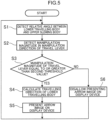
- FIG. 5 is a flowchart of a display control of the construction machine 1. An operation of the construction machine 1 will now be described using FIG. 5 .
- the controller 6 detects the relative angle between the lower travelling body 21 and the upper slewing body 22 from the detected result of the angle detecting device 4 (step S1). Then, the controller 6 detects the manipulation direction and the manipulation magnitude of the travel lever 2 from the detected result of the manipulation magnitude detecting device 5 (step S2).
- the controller 6 determines whether the manipulation magnitude of the travel lever 2 is equal to or greater than the second threshold value (step S3). If it is determined in step S3 that the manipulation magnitude of the travel lever 2 is equal to or greater than the second threshold value (S3: YES), the controller 6 calculates the travelling direction of the lower travelling body 21 based on the detected result of the angle detecting device 4 and the manipulation direction of the travel lever 2 (step S4). The controller 6 makes the display device 3 display the arrow image 50 (step S5). The step returns to step S1.
- step S3 determines whether the manipulation magnitude of the travel lever 2 is not equal to or not greater than the second threshold value (S3: NO).
- step S6 determines whether the manipulation magnitude of the travel lever 2 is not equal to or not greater than the second threshold value (S3: NO).
- the arrow image 50 indicating the travelling direction of the lower travelling body 21 is displayed on the display device 3 when the travel lever 2 is manipulated while the arrow image 50 indicating the travelling direction of the lower travelling body 21 is not displayed on the display device 3 when the travel lever 2 is not manipulated. Since the arrow image 50 indicating the travelling direction of the lower travelling body 21 is displayed on the display device 3 when a manipulation is given to make the lower travelling body 21 travel, it is not likely that the arrow image 50 causes disturbance during an operation other than travelling. Deterioration in work efficiency can thus be suppressed.
- the operator when the operator manipulates the travel lever 2 while manipulating a slew lever or an attachment manipulating lever disposed in the cab 23 like the travel lever 2, the operator can check the travelling direction of the lower travelling body 21 by the arrow image 50. Meanwhile, when the operator does not manipulate the travel lever 2 while manipulating the slew lever or the attachment manipulating lever, the arrow image 50 is not displayed and the operator can concentrate on slewing or manipulating the attachment.
- the travelling direction of the lower travelling body 21 is obtained based on the detected result of the angle detecting device 4 and the manipulation direction of the travel lever 2.
- the arrow image 50 indicating the travelling direction of the lower travelling body 21 is displayed on the display device 3.
- the display device 3 can display the arrow image 50 indicating the travelling direction of the lower travelling body 21 when the lower travelling body 21 travels forward or backward, the directions indicated by the arrow image 50 for forward and backward travelling being opposite to each other. In either case of the lower travelling body 21 travelling forward or backward, the operator can correctly recognize the travelling direction of the lower travelling body 21.
- the controller 6 makes the display device 3 display the arrow image 50 indicating the travelling direction of the lower travelling body 21.
- the second threshold value is larger than 0 but smaller than the first threshold value. This enables the display device 3 to display the arrow image 50 indicating the travelling direction of the lower travelling body 21 when the manipulation magnitude of the travel lever 2 is smaller than the first threshold value at which the lower travelling body 21 starts travelling, namely, in a state where the manipulation magnitude is within a "play". This enables the operator to recognize the travelling direction of the lower travelling body 21 in a state where the lower travelling body 21 has not yet started travelling (state before starting travelling).
- a see-through display device 3 is disposed on the front windshield glass 24 of the cab 23. Since the arrow image 50 indicating the travelling direction of the lower travelling body 21 is superposed on the sight seen through the front windshield glass 24, the operator can check the travelling direction of the lower travelling body 21 while seeing the sight of working without checking the position of the lower travelling body 21 through the front windshield glass 24. Thus, moving the eyesight is less required compared to when the display device 3 is disposed at a place separated from the front windshield glass 24, so that deterioration in work efficiency can be suppressed.
- FIG. 6 is a top view of a construction machine 101 according to the embodiment.
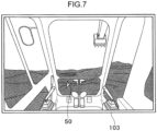
- FIG. 7 is a view illustrating a screen of a display device 103 according to the embodiment.
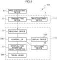
- FIG. 8 is a block diagram of the construction machine 101 according to the embodiment.
- description on the configuration common to the first embodiment and the effect obtained by the configuration are omitted.
- a feature different from the first embodiment will mainly be described.
- the member same as that in the first embodiment will be appended with the same reference sign.
- the operator in the cab 23 operates the machine body 20.
- an operator outside the construction machine 101 remotely operates the machine body 20.
- the construction machine 101 includes a slave device 111 provided to the machine body 20, and a master device 112 for remotely operating the slave device 111.
- the master device 112 is provided in an operating region which is disposed at a place remote from the machine body 20, and is electrically connected by wire or wirelessly to the slave device 111.
- the operating region may be a remote control unit disposed at a location from which the construction machine 101 can be seen or a control center disposed at a place remote from the construction machine 101.
- the slave device 111 ( FIG. 8 ) includes a plurality of image capturing devices 7 (at least one image capturing device).
- a plurality of the image capturing devices 7 are provided on the upper slewing body 22 to be oriented to predetermined image capturing directions to capture sights seen from the upper slewing body 22.
- a plurality of the image capturing devices 7 are positioned to be oriented to different image capturing directions.
- a plurality of the image capturing devices 7 are provided in the cab 23 and include an image capturing device 7A that captures an image of a front sight of the upper slewing body 22 through the front windshield glass 24, an image capturing device 7B that captures an image of a right sight of the upper slewing body 22, an image capturing device 7C that captures an image of a left sight of the upper slewing body 22, and an image capturing device 7D that captures an image of a rear sight of the upper slewing body 22.
- An arrow pointing the left bottom in FIG. 6 is a direction in which the lower travelling body 21 which is slewed relative to the upper slewing body 22 travels backward.
- a triangle extending from each of the image capturing devices 7 schematically indicates an angle of view (a view angle) of the image capturing device 7.
- the master device 112 includes a travel lever 2M, and the display device 103 ( FIG. 8 ).
- the travel lever 2M is similar to the travel lever 2 disposed in the cab 23 as shown in FIG. 2 .
- the manipulation magnitude of the travel lever 2M is detected by a manipulation magnitude detecting device 5.
- the display device 103 is disposed in a place remote from the machine body 20 (remote place) so as to be seen by the operator.
- the display device 103 is a liquid crystal display disposed in a room in the remote place.
- a sight image captured by the image capturing device 7 provided to the machine body 20 is displayed on the display device 103.
- a sight image captured by the image capturing device 7A which captures a front sight of the upper slewing body 22, is displayed on the display device 103, as an example.
- the slave device 111 includes a transmitting device 8.
- the transmitting device 8 transmits sight images captured by the image capturing devices 7 (7A to 7D) and the detected result of an angle detecting device 6 to the master device 112.
- the master device 112 includes a receiving device 9, the manipulation magnitude detecting device 5, and a controller 106.
- the receiving device 9 receives the sight images transmitted by the transmitting device 8 and the detected result of the angle detecting device 6.
- the controller (display controlling unit) 106 makes the display device 103 display the sight images captured by the image capturing device 7.
- the master device 112 includes a selecting device 10.
- the selecting device 10 selects one among a plurality of the image capturing devices 7 in response to a manipulation made by the operator.
- the controller 106 makes the display device 103 display the sight image captured by the image capturing device 7 selected by the selecting device 10. For example, when the image capturing device 7 that captures an image of a rear sight of the upper slewing body 22 is selected, a sight image of the rear sight of the upper slewing body 22 captured by the image capturing device 7 is displayed on the display device 103.
- the controller (directional information generating unit) 106 calculates a travelling direction of the lower travelling body 21 based on the detected result of the angle detecting device 6 and the manipulation direction of the travel lever 2M.
- the controller 106 calculates (generates) the travelling direction (directional information) of the lower travelling body 21 based on the image capturing direction of the image capturing device 7 selected by the selecting device 10 and the detected result of the angle detecting device 6 and outputs the information.
- the controller (display controlling unit) 106 makes the display device 103 superpose the arrow image 50 on the sight image displayed by the display device 103.
- This enables the operator to check the travelling direction of the lower travelling body 21 while seeing the sight image. The operator is less required to move the eyesight, and thus deterioration of work efficiency can be suppressed.
- the direction indicated by the arrow image 50 in FIG. 7 is the backward travelling direction of the lower travelling body 21 indicated by an arrow in FIG. 6 .
- the controller 106 superposes the arrow image 50 on the sight image captured by the image capturing device 7 selected by the selecting device 10.
- the image capturing direction is switched and the arrow image 50 corresponding to the image capturing direction of the selected image capturing device 7 is superposed on the sight image. This enables the operator to correctly recognize the travelling direction of the lower travelling body 21 when a sight image captured by any one of the image capturing devices 7 is displayed on the display device 103.
- the arrow image 50 indicating the travelling direction of the lower travelling body 21 is not displayed on the display device 103, and when the manipulation magnitude of the travel lever 2M becomes equal to or greater than the second threshold value, the arrow image 50 indicating the travelling direction of the lower travelling body 21 is displayed on the display device 103.
- the travel lever 2M, the display device 103, the receiving device 9, the selecting device 10, and the controller 106 are provided in the operating region placed outside the machine body 20.
- the arrow image 50 indicating the travelling direction of the lower travelling body 21 is superposed on the sight image displayed on the display device 103.
- the operator can check the travelling direction of the lower travelling body 21 while seeing the sight image.
- the operator is less required to move the eyesight, and thus deterioration of work efficiency can be suppressed.
- the travelling direction of the lower travelling body 21 is calculated (obtained) based on the image capturing direction of the image capturing device 7 selected by the selecting device 10 and the detected result of the angle detecting device 6.
- the arrow image 50 indicating the travelling direction of the lower travelling body 21 is superposed on the sight image captured by the image capturing device 7 selected by the selecting device 10.
- the arrow image 50 corresponding to the image capturing direction of the image capturing device 7 is superposed on the sight image. This enables the operator to correctly recognize the travelling direction of the lower travelling body 21 when a sight image captured by any one of the image capturing devices 7 is displayed on the display device 103.
- the display device 3 displays the arrow image 50 indicating the travelling direction of the lower travelling body 21 when the travel lever 2 (2M) is tilted forward (when the lower travelling body 21 travels forward) and when the travel lever 2 is tilted backward (when the lower travelling body 21 travels backward), the directions indicated by the arrow image 50 for forward and backward travelling being opposite to each other.
- the display device 3 may always display the arrow image 50 indicating the direction in which the lower travelling body 21 travels forward as the travelling direction no matter which manipulation direction the travel lever 2 is manipulated.
Landscapes
- Engineering & Computer Science (AREA)
- Mining & Mineral Resources (AREA)
- Civil Engineering (AREA)
- General Engineering & Computer Science (AREA)
- Structural Engineering (AREA)
- Multimedia (AREA)
- Mechanical Engineering (AREA)
- Transportation (AREA)
- Combustion & Propulsion (AREA)
- Chemical & Material Sciences (AREA)
- Signal Processing (AREA)
- Component Parts Of Construction Machinery (AREA)
- Closed-Circuit Television Systems (AREA)
Description
- The present invention relates to a construction machine including a lower travelling body and an upper slewing body that is provided on an upper portion of the lower travelling body and is slewable.
- In a construction machine including a lower travelling body and an upper slewing body that is provided on an upper portion of the lower travelling body and is slewable, a traveling direction of the lower travelling body recognized by an operator in a cab provided to the upper slewing body differs for different slew angles of the upper slewing body relative to the lower travelling body. Therefore, the operator manipulating the lower travelling body to travel might get disoriented and cannot recognize which direction the lower travelling body is travelling.
-
Patent Literature 1 discloses a monitoring device provided to the construction machine and configured to estimate a relative angle of a lower travelling body to an upper slewing body from a chronological change in an image displayed on a monitor screen and display estimated angle information on the monitor screen. Since the correct angle information of the upper slewing body (direction indicated by an arrow) is displayed on the monitor screen even when the upper slewing body slews, the operator can make the lower travelling body travel based on the angle information. - In the technique described in
Patent Literature 1, the angle information of the upper slewing body is always displayed on the monitor screen. During an operation other than travelling, the angle information displayed on the monitor screen might disturb the operator and deteriorate work efficiency.JP 2007-198040 A claim 1, comprising a travelling direction display device, which is provided with a turning angle detection means for detecting the turning angle of the upper turning body with respect of the lower travelling body and a travelling operation detection means for detecting the operation of the operating tool for travelling. The travelling direction of the machine body with the driver's seat as a standard is displayed in a display part of a monitor device based on a detection signal outputted from the turning angle detection means and the travelling operation detection means.EP 2009-173195 A - Patent Literature 1:
JP 5473870 B2 JP2007-198040 A JP2007-173195 A - An object of the present invention is to provide a construction machine in which an operator in a cab of an upper slewing body can recognize a travelling direction of a lower travelling body, and deterioration in work efficiency when the lower travelling body is not travelling can be suppressed.
- The present invention provides a construction machine according to
claim 1. Further developments of the invention are described in the subclaims. -
-
FIG. 1 is a side view of a construction machine -
FIG. 2 is a view looking a front sight of an upper slewing body from inside a cab of the construction machine inFIG. 1 . -
FIG. 3 is a figure illustrating a relationship between a tilt angle (manipulation magnitude) of a travel lever and an output value of pilot pressure of the construction machine inFIG. 1 . -
FIG. 4 is a block diagram of the construction machine inFIG. 1 . -
FIG. 5 is a flowchart of a display control of the construction machine inFIG. 1 . -
FIG. 6 is a top view of the construction machine according to an embodiment of the present invention. -
FIG. 7 is a view illustrating a screen of a display device according to the embodiment of the present invention. -
FIG. 8 is a block diagram of the construction machine according to the embodiment of the present invention. - Preferable embodiments of the present invention will be described with reference to the drawings.
-
FIG. 1 is a side view of aconstruction machine 1. As illustrated inFIG. 1 , theconstruction machine 1 is a machine that works using anattachment 30, for example, a hydraulic excavator. Theconstruction machine 1 includes amachine body 20 including alower travelling body 21, anupper slewing body 22, theattachment 30, and acylinder 40. - The
lower travelling body 21 is a part that makes theconstruction machine 1 travel. For example, thelower travelling body 21 includes a crawler and is capable of traveling on the ground. Theupper slewing body 22 is attached to an upper portion of thelower travelling body 21 via a slewing device and is able to slew about a rotational axis extending in the up-and-down direction. A cab (operation room) 23 that has a window and allows an operator (worker) to get inside is provided to a front portion of theupper slewing body 22. - The
attachment 30 is attached to theupper slewing body 22. Theattachment 30 includes aboom 31, anarm 32, and abucket 33. Theboom 31 is attached to theupper slewing body 22 and is able to pivot about a horizontal pivot axis (can be raised and lowered). Thearm 32 is attached to theboom 31 and is able to pivot about a horizontal pivot axis. Thebucket 33 is attached to thearm 32 and is able to pivot about a horizontal pivot axis. Thebucket 33 is used to perform works, such as excavation, flattening, and digging up of a work subject (earth, sand, etc.). - The
cylinder 40 operates theattachment 30. Thecylinder 40 is a hydraulic extend/contract cylinder. Thecylinder 40 includes aboom cylinder 41, anarm cylinder 42, and abucket cylinder 43. - The
boom cylinder 41 rotationally drives (pivots) theboom 31 relative to theupper slewing body 22. A proximal end portion of theboom cylinder 41 is pivotally attached to theupper slewing body 22. The distal end portion of theboom cylinder 41 is pivotally attached to theboom 31. - The
arm cylinder 42 rotationally drives thearm 32 relative to theboom 31. The proximal end portion of thearm cylinder 42 is pivotally attached to theboom 31. The distal end portion of thearm cylinder 42 is pivotally attached to thearm 32. - The
bucket cylinder 43 rotationally drives thebucket 33 relative to thearm 32. The proximal end portion of thebucket cylinder 43 is pivotally attached to thearm 32. The distal end portion of thebucket cylinder 43 is pivotally attached to a link member pivotally attached to thebucket 33. -
FIG. 2 is a view looking a front sight of theupper slewing body 22 from inside thecab 23 of theconstruction machine 1 inFIG. 1 . As illustrated inFIG. 2 , theconstruction machine 1 includes atravel lever 2. Thetravel lever 2 is tiltable in front-and-rear direction. An operator manipulates thetravel lever 2 to make thelower travelling body 21 travel. That is, thetravel lever 2 receives a manipulation by the operator who makes thelower travelling body 21 travel. The travelling direction of thelower travelling body 21 is switched between forward travelling and backward travelling according to the manipulation direction of thetravel lever 2. That is, thetravel lever 2 can receive a manipulation in a plurality of manipulation directions including a forward manipulating direction to make thelower travelling body 21 travel forward and a backward manipulating direction to make thelower travelling body 21 travel backward. Specifically, thelower travelling body 21 travels forward by the operator tilting thetravel lever 2 forward (in the forward manipulating direction), and thelower travelling body 21 travels backward by the operator tilting thetravel lever 2 backward (in the backward manipulating direction). The manipulation magnitude of the manipulation received by thetravel lever 2 is detected by a manipulationmagnitude detecting device 5 which will be described later. -
FIG. 3 is a figure illustrating a relationship between a tilt angle (manipulation magnitude) of thetravel lever 2 and an output value of pilot pressure of theconstruction machine 1 according to the embodiment. As illustrated inFIG. 3 , when the manipulation magnitude received by thetravel lever 2 is "0" or higher but smaller than a first threshold value, the output value of the pilot pressure is constant at a predetermined value, and when the manipulation magnitude received by thetravel lever 2 is greater than the first threshold value, the output value of the pilot pressure increases above the predetermined value. When the output value of the pilot pressure exceeds the predetermined value, the lower travellingbody 21 starts traveling (forward or backward). That is, when the manipulation magnitude received by thetravel lever 2 is "0" or greater but smaller than the first threshold value, the lower travellingbody 21 stays still. As described above, the manipulation magnitude of thetravel lever 2 has a "play". - As illustrated in
FIG. 2 , theconstruction machine 1 includes adisplay device 3. Thedisplay device 3 is disposed to be in an eyesight of the operator and displays information. Thedisplay device 3 is of a see-through type and disposed in a portion of a front windshield glass (window) 24. Thedisplay device 3 includes, for example, a see-through organic EL display. The operator can see a sight outside through thedisplay device 3. -
FIG. 4 is a block diagram of theconstruction machine 1. As illustrated inFIG. 4 , theconstruction machine 1 further includes anangle detecting device 4, a manipulationmagnitude detecting device 5, and acontroller 6. - The
angle detecting device 4 is provided to themachine body 20 and detects a relative angle (slew angle) between the lower travellingbody 21 and theupper slewing body 22 about the rotational axis. Although theangle detecting device 4 detects the slew angle of the lower travellingbody 21 relative to theupper slewing body 22, theangle detecting device 4 may detect a slew angle of theupper slewing body 22 relative to the lower travellingbody 21. - The manipulation
magnitude detecting device 5 detects a manipulation magnitude (tilt angle) of the manipulation received by thetravel lever 2 and a manipulation direction of thetravel lever 2. Specifically, the manipulationmagnitude detecting device 5 detects a tilt angle of thetravel lever 2 tilted forward and a tilt angle of thetravel lever 2 tilted backward. - The controller (directional information generating unit) 6 calculates (generates) and outputs a travelling direction of the lower travelling
body 21 based on the detected result of theangle detecting device 4 and the manipulation direction of thetravel lever 2. In particular, the front-and-rear direction (directional information) of the lower travellingbody 21 is calculated by the detected result of theangle detecting device 4. From the manipulation direction of thetravel lever 2, the direction in which the lower travellingbody 21 travels forward or backward is obtained as a travelling direction (directional information). That is, when the manipulation direction of thetravel lever 2 is the forward direction, the direction in which the lower travellingbody 21 travels forward is obtained as the travelling direction, and when the manipulation direction of thetravel lever 2 is the backward direction, the direction in which the lower travellingbody 21 travels backward is obtained as the travelling direction. Thecontroller 6 may include a storing unit and compare the detected result of theangle detecting device 4 with information (table) stored in the storing unit to obtain the travelling direction of the lower travellingbody 21. - The controller (display controlling unit) 6 makes the
display device 3 display an image indicating the calculated travelling direction of the lower travellingbody 21 when thetravel lever 2 is manipulated. As illustrated inFIG. 2 , anarrow image 50 having a shape of an arrow is displayed on thedisplay device 3. Thearrow image 50 is superposed on the sight seen through thefront windshield glass 24. The direction indicated by thearrow image 50 changes based on the detected result of theangle detecting device 4 and the manipulation direction of thetravel lever 2. For example, when the lower travellingbody 21 is slewed to the right side relative to theupper slewing body 22 and travels backward, thearrow image 50 indicates the direction toward the left bottom as illustrated inFIG. 2 . The image indicating the travelling direction of the lower travellingbody 21 is not limited to thearrow image 50 but may be any image by which the travelling direction of the lower travellingbody 21 can be recognized, for example, an icon image of the lower travellingbody 21. - In other words, the
controller 6 generates and outputs directional information which is related to the travelling direction of the lower travellingbody 21 relative to theupper slewing body 22 based on at least the detected result of theangle detecting device 4. Furthermore, when thetravel lever 2 is receiving a manipulation by the operator, thecontroller 6 controls thedisplay device 3 to displays a directional information image (the arrow image 50) indicating the directional information whereas, when thetravel lever 2 is not receiving a manipulation, thecontroller 6 controls thedisplay device 3 not to display the directional information image. - Since the
arrow image 50 indicating the travelling direction of the lower travellingbody 21 is superposed on the sight seen through thefront windshield glass 24 as described above, the operator can check the travelling direction of the lower travellingbody 21 while seeing the sight of working without checking the position of the lower travellingbody 21 through thefront windshield glass 24. Thus, moving the eyesight is less required compared to when thedisplay device 3 is disposed at a place separated from thefront windshield glass 24, so that deterioration in work efficiency can be suppressed. - Furthermore, the
controller 6 calculates the travelling direction of the lower travellingbody 21 based on the detected result of theangle detecting device 4 and the manipulation direction of thetravel lever 2 as described above. Thus, thedisplay device 3 can display thearrow image 50 indicating the travelling direction of the lower travellingbody 21 when the lower travellingbody 21 travels forward or backward, the directions indicated by thearrow image 50 for forward and backward travelling being opposite to each other. In either case of the lower travellingbody 21 travelling forward or backward, the operator can correctly recognize the travelling direction of the lower travellingbody 21. - The
controller 6 makes thedisplay device 3 display thearrow image 50 when the manipulation magnitude of thetravel lever 2 detected by the manipulationmagnitude detecting device 5 becomes equal to or greater than a second threshold value (seeFIG. 3 ) which is larger than 0 but smaller than the first threshold value. This enables thedisplay device 3 to display thearrow image 50 indicating the travelling direction of the lower travellingbody 21 when the manipulation magnitude of thetravel lever 2 is smaller than the first threshold value at which the lower travellingbody 21 starts travelling, namely, in a state where the manipulation magnitude is within a "play". This enables the operator to recognize the travelling direction of the lower travellingbody 21 in a state where the lower travellingbody 21 has not yet started travelling. - Meanwhile, the
controller 6 does not let thedisplay device 3 display thearrow image 50 when thetravel lever 2 is not manipulated. Thearrow image 50 indicating the travelling direction of the lower travellingbody 21 is displayed on thedisplay device 3 when a manipulation is given to make the lower travellingbody 21 travel (more specifically, the manipulation includes a state where the manipulation magnitude of thetravel lever 2 is within a "play"), so that it is not likely that thearrow image 50 causes disturbance during an operation other than travelling. Deterioration in work efficiency can thus be suppressed. -
FIG. 5 is a flowchart of a display control of theconstruction machine 1. An operation of theconstruction machine 1 will now be described usingFIG. 5 . - First, the
controller 6 detects the relative angle between the lower travellingbody 21 and theupper slewing body 22 from the detected result of the angle detecting device 4 (step S1). Then, thecontroller 6 detects the manipulation direction and the manipulation magnitude of thetravel lever 2 from the detected result of the manipulation magnitude detecting device 5 (step S2). - The
controller 6 then determines whether the manipulation magnitude of thetravel lever 2 is equal to or greater than the second threshold value (step S3). If it is determined in step S3 that the manipulation magnitude of thetravel lever 2 is equal to or greater than the second threshold value (S3: YES), thecontroller 6 calculates the travelling direction of the lower travellingbody 21 based on the detected result of theangle detecting device 4 and the manipulation direction of the travel lever 2 (step S4). Thecontroller 6 makes thedisplay device 3 display the arrow image 50 (step S5). The step returns to step S1. - Meanwhile, if it is determined in step S3 that the manipulation magnitude of the
travel lever 2 is not equal to or not greater than the second threshold value (S3: NO), thecontroller 6 does not let thedisplay device 3 display the arrow image 50 (step S6). The step returns to step S1. - In the
construction machine 1 as described above, thearrow image 50 indicating the travelling direction of the lower travellingbody 21 is displayed on thedisplay device 3 when thetravel lever 2 is manipulated while thearrow image 50 indicating the travelling direction of the lower travellingbody 21 is not displayed on thedisplay device 3 when thetravel lever 2 is not manipulated. Since thearrow image 50 indicating the travelling direction of the lower travellingbody 21 is displayed on thedisplay device 3 when a manipulation is given to make the lower travellingbody 21 travel, it is not likely that thearrow image 50 causes disturbance during an operation other than travelling. Deterioration in work efficiency can thus be suppressed. In particular, when the operator manipulates thetravel lever 2 while manipulating a slew lever or an attachment manipulating lever disposed in thecab 23 like thetravel lever 2, the operator can check the travelling direction of the lower travellingbody 21 by thearrow image 50. Meanwhile, when the operator does not manipulate thetravel lever 2 while manipulating the slew lever or the attachment manipulating lever, thearrow image 50 is not displayed and the operator can concentrate on slewing or manipulating the attachment. - Furthermore, the travelling direction of the lower travelling
body 21 is obtained based on the detected result of theangle detecting device 4 and the manipulation direction of thetravel lever 2. Thearrow image 50 indicating the travelling direction of the lower travellingbody 21 is displayed on thedisplay device 3. Thedisplay device 3 can display thearrow image 50 indicating the travelling direction of the lower travellingbody 21 when the lower travellingbody 21 travels forward or backward, the directions indicated by thearrow image 50 for forward and backward travelling being opposite to each other. In either case of the lower travellingbody 21 travelling forward or backward, the operator can correctly recognize the travelling direction of the lower travellingbody 21. - When the manipulation magnitude of the
travel lever 2 detected by the manipulationmagnitude detecting device 5 becomes equal to or greater than the second threshold value, thecontroller 6 makes thedisplay device 3 display thearrow image 50 indicating the travelling direction of the lower travellingbody 21. The second threshold value is larger than 0 but smaller than the first threshold value. This enables thedisplay device 3 to display thearrow image 50 indicating the travelling direction of the lower travellingbody 21 when the manipulation magnitude of thetravel lever 2 is smaller than the first threshold value at which the lower travellingbody 21 starts travelling, namely, in a state where the manipulation magnitude is within a "play". This enables the operator to recognize the travelling direction of the lower travellingbody 21 in a state where the lower travellingbody 21 has not yet started travelling (state before starting travelling). - A see-through
display device 3 is disposed on thefront windshield glass 24 of thecab 23. Since thearrow image 50 indicating the travelling direction of the lower travellingbody 21 is superposed on the sight seen through thefront windshield glass 24, the operator can check the travelling direction of the lower travellingbody 21 while seeing the sight of working without checking the position of the lower travellingbody 21 through thefront windshield glass 24. Thus, moving the eyesight is less required compared to when thedisplay device 3 is disposed at a place separated from thefront windshield glass 24, so that deterioration in work efficiency can be suppressed. - A construction machine according to an embodiment of the present invention will be described with reference to the drawings.
FIG. 6 is a top view of aconstruction machine 101 according to the embodiment.FIG. 7 is a view illustrating a screen of adisplay device 103 according to the embodiment.FIG. 8 is a block diagram of theconstruction machine 101 according to the embodiment. In the embodiment, description on the configuration common to the first embodiment and the effect obtained by the configuration are omitted. A feature different from the first embodiment will mainly be described. In the description below and inFIGS. 6 to 8 , the member same as that in the first embodiment will be appended with the same reference sign. - In the
construction machine 1 as shown inFIG. 2 , the operator in thecab 23 operates themachine body 20. In contrast, in theconstruction machine 101 according to the present invention, an operator outside theconstruction machine 101 remotely operates themachine body 20. - The
construction machine 101 according to the embodiment includes aslave device 111 provided to themachine body 20, and amaster device 112 for remotely operating theslave device 111. Themaster device 112 is provided in an operating region which is disposed at a place remote from themachine body 20, and is electrically connected by wire or wirelessly to theslave device 111. The operating region may be a remote control unit disposed at a location from which theconstruction machine 101 can be seen or a control center disposed at a place remote from theconstruction machine 101. - As illustrated in
FIG. 6 , the slave device 111 (FIG. 8 ) includes a plurality of image capturing devices 7 (at least one image capturing device). A plurality of theimage capturing devices 7 are provided on theupper slewing body 22 to be oriented to predetermined image capturing directions to capture sights seen from theupper slewing body 22. A plurality of theimage capturing devices 7 are positioned to be oriented to different image capturing directions. In the embodiment, a plurality of theimage capturing devices 7 are provided in thecab 23 and include animage capturing device 7A that captures an image of a front sight of theupper slewing body 22 through thefront windshield glass 24, animage capturing device 7B that captures an image of a right sight of theupper slewing body 22, animage capturing device 7C that captures an image of a left sight of theupper slewing body 22, and an image capturing device 7D that captures an image of a rear sight of theupper slewing body 22. An arrow pointing the left bottom inFIG. 6 is a direction in which the lower travellingbody 21 which is slewed relative to theupper slewing body 22 travels backward. A triangle extending from each of theimage capturing devices 7 schematically indicates an angle of view (a view angle) of theimage capturing device 7. - The
master device 112 includes atravel lever 2M, and the display device 103 (FIG. 8 ). Thetravel lever 2M is similar to thetravel lever 2 disposed in thecab 23 as shown inFIG. 2 . The manipulation magnitude of thetravel lever 2M is detected by a manipulationmagnitude detecting device 5. Thedisplay device 103 is disposed in a place remote from the machine body 20 (remote place) so as to be seen by the operator. For example, thedisplay device 103 is a liquid crystal display disposed in a room in the remote place. - As illustrated in
FIG. 7 , a sight image captured by theimage capturing device 7 provided to themachine body 20 is displayed on thedisplay device 103. InFIG. 7 , a sight image captured by theimage capturing device 7A, which captures a front sight of theupper slewing body 22, is displayed on thedisplay device 103, as an example. - As illustrated in
FIG. 8 , theslave device 111 includes a transmittingdevice 8. The transmittingdevice 8 transmits sight images captured by the image capturing devices 7 (7A to 7D) and the detected result of anangle detecting device 6 to themaster device 112. - The
master device 112 includes a receiving device 9, the manipulationmagnitude detecting device 5, and acontroller 106. The receiving device 9 receives the sight images transmitted by the transmittingdevice 8 and the detected result of theangle detecting device 6. The controller (display controlling unit) 106 makes thedisplay device 103 display the sight images captured by theimage capturing device 7. - The
master device 112 includes a selectingdevice 10. The selectingdevice 10 selects one among a plurality of theimage capturing devices 7 in response to a manipulation made by the operator. Thecontroller 106 makes thedisplay device 103 display the sight image captured by theimage capturing device 7 selected by the selectingdevice 10. For example, when theimage capturing device 7 that captures an image of a rear sight of theupper slewing body 22 is selected, a sight image of the rear sight of theupper slewing body 22 captured by theimage capturing device 7 is displayed on thedisplay device 103. - As described previously, the controller (directional information generating unit) 106 calculates a travelling direction of the lower travelling
body 21 based on the detected result of theangle detecting device 6 and the manipulation direction of thetravel lever 2M. Thecontroller 106 calculates (generates) the travelling direction (directional information) of the lower travellingbody 21 based on the image capturing direction of theimage capturing device 7 selected by the selectingdevice 10 and the detected result of theangle detecting device 6 and outputs the information. - As illustrated in
FIG. 7 , when thetravel lever 2M is manipulated, the controller (display controlling unit) 106 makes thedisplay device 103 superpose thearrow image 50 on the sight image displayed by thedisplay device 103. This enables the operator to check the travelling direction of the lower travellingbody 21 while seeing the sight image. The operator is less required to move the eyesight, and thus deterioration of work efficiency can be suppressed. The direction indicated by thearrow image 50 inFIG. 7 is the backward travelling direction of the lower travellingbody 21 indicated by an arrow inFIG. 6 . - The
controller 106 superposes thearrow image 50 on the sight image captured by theimage capturing device 7 selected by the selectingdevice 10. When anotherimage capturing device 7 is selected, the image capturing direction is switched and thearrow image 50 corresponding to the image capturing direction of the selectedimage capturing device 7 is superposed on the sight image. This enables the operator to correctly recognize the travelling direction of the lower travellingbody 21 when a sight image captured by any one of theimage capturing devices 7 is displayed on thedisplay device 103. - As described previously, when the manipulation magnitude of the
travel lever 2M is smaller than the second threshold value, thearrow image 50 indicating the travelling direction of the lower travellingbody 21 is not displayed on thedisplay device 103, and when the manipulation magnitude of thetravel lever 2M becomes equal to or greater than the second threshold value, thearrow image 50 indicating the travelling direction of the lower travellingbody 21 is displayed on thedisplay device 103. - That is, in the embodiment, the
travel lever 2M, thedisplay device 103, the receiving device 9, the selectingdevice 10, and the controller 106 (directional information generating unit and display controlling unit) are provided in the operating region placed outside themachine body 20. - In the
construction machine 101 according to the embodiment as described above, thearrow image 50 indicating the travelling direction of the lower travellingbody 21 is superposed on the sight image displayed on thedisplay device 103. The operator can check the travelling direction of the lower travellingbody 21 while seeing the sight image. The operator is less required to move the eyesight, and thus deterioration of work efficiency can be suppressed. - The travelling direction of the lower travelling
body 21 is calculated (obtained) based on the image capturing direction of theimage capturing device 7 selected by the selectingdevice 10 and the detected result of theangle detecting device 6. Thearrow image 50 indicating the travelling direction of the lower travellingbody 21 is superposed on the sight image captured by theimage capturing device 7 selected by the selectingdevice 10. When anotherimage capturing device 7 is selected, thearrow image 50 corresponding to the image capturing direction of theimage capturing device 7 is superposed on the sight image. This enables the operator to correctly recognize the travelling direction of the lower travellingbody 21 when a sight image captured by any one of theimage capturing devices 7 is displayed on thedisplay device 103. - Each of the embodiments of the present invention described above is merely a specific example and does not limit the scope of the present invention. Specific configurations can suitably be redesigned. The described effect of the embodiment of the present invention is the most preferable effect that can be obtained by the present invention. The effect of the present invention is not limited to that of the described embodiments of the present invention.
- For example, in the above description, the
display device 3 displays thearrow image 50 indicating the travelling direction of the lower travellingbody 21 when the travel lever 2 (2M) is tilted forward (when the lower travellingbody 21 travels forward) and when thetravel lever 2 is tilted backward (when the lower travellingbody 21 travels backward), the directions indicated by thearrow image 50 for forward and backward travelling being opposite to each other. However, thedisplay device 3 may always display thearrow image 50 indicating the direction in which the lower travellingbody 21 travels forward as the travelling direction no matter which manipulation direction thetravel lever 2 is manipulated.
Claims (3)
- A construction machine (1) comprising:a machine body (20) including a lower travelling body (21) that can travel on a ground, and an upper slewing body (22) that is provided on an upper portion of the lower travelling body (21) and can slew about a rotational axis extending in an up-and-down direction;an angle detecting device (4) provided to the machine body (20) to detect a relative angle between the lower travelling body (21) and the upper slewing body (22) about the rotational axis;a travel lever (2M) that receives a manipulation for making the lower travelling body travel (21);a display device (103) disposed within an eyesight of a worker;a directional information generating unit (106) that generates directional information related to a travelling direction of the lower travelling body (21) relative to the upper slewing body (22) based on at least a detected result of the angle detecting device (4); anda display controlling unit (106) that controls the display device (103) to display a directional information image indicating the directional information on the display device (103) when the travel lever (2M) receives the manipulation, and not to display the directional information image on the display device (103) when the travel lever (2M) does not receive the manipulation,characterized in thatthe travel lever (2M), the display device (103), the directional information generating unit (106), and the display controlling unit (106) are provided in an operating region placed outside the machine body (20);the construction machine (1) further comprises at least one image capturing device (7) that is provided to the upper slewing body (22) to be oriented to a predetermined image capturing direction and captures an image of a sight seen from the upper slewing body (22), a transmitting device (8) that is provided to the machine body (20) and transmits a sight image captured by the at least one image capturing device (7) and the detected result of the angle detecting device (4) to the operating region, and a receiving device (9) that is provided in the operating region and receives the sight image and the detected result of the angle detecting device (4) transmitted from the transmitting device (8),the display controlling unit (106) makes the display device (103) display the sight image and superpose the directional information image on the sight image,the at least one image capturing device (7) includes a plurality of image capturing devices set to different image capturing directions,the construction machine (1) further comprises a selecting device (10) that is provided in the operating region and selects one among the plurality of image capturing devices,the directional information generating unit (106) generates the directional information based on the image capturing direction of the one among the image capturing devices selected by the selecting device (10) and the detected result of the angle detecting device (4), andthe display controlling unit (106) makes the display device (103) display the sight image captures by the one among the image capturing devices and superpose the directional information image on the sight image.
- The construction machine (1) according to claim 1, whereinthe travel lever (2M) is able to receive the manipulation in a plurality of manipulation directions including a forward manipulating direction for making the lower travelling body (21) travel forward and a backward manipulating direction for making the lower travelling body (21) travel backward, andthe directional information generating unit (106) generates the directional information based on the detected result of the angle detecting device (4) and the manipulation direction of the manipulation received by the travel lever (2M).
- The construction machine (1) according to claim 1 or 2, whereinthe lower travelling body (21) starts travelling when a manipulation magnitude of the manipulation received by the travel lever (2M) exceeds a first threshold value,the construction machine (1) further comprises a manipulation magnitude detecting device (5) that detects the manipulation magnitude received by the travel lever (2M), andthe display controlling unit (106) makes the display device (103) display the directional information image when the manipulation magnitude of the travel lever (2M) detected by the manipulation magnitude detecting device (5) is equal to or greater than a second threshold value greater than 0 and smaller than the first threshold value.
Applications Claiming Priority (2)
| Application Number | Priority Date | Filing Date | Title |
|---|---|---|---|
| JP2018055964A JP7063036B2 (en) | 2018-03-23 | 2018-03-23 | Construction machinery |
| PCT/JP2019/001128 WO2019181159A1 (en) | 2018-03-23 | 2019-01-16 | Construction machine |
Publications (3)
| Publication Number | Publication Date |
|---|---|
| EP3739131A1 EP3739131A1 (en) | 2020-11-18 |
| EP3739131A4 EP3739131A4 (en) | 2021-03-24 |
| EP3739131B1 true EP3739131B1 (en) | 2024-03-27 |
Family
ID=67987119
Family Applications (1)
| Application Number | Title | Priority Date | Filing Date |
|---|---|---|---|
| EP19772496.6A Active EP3739131B1 (en) | 2018-03-23 | 2019-01-16 | Construction machine |
Country Status (5)
| Country | Link |
|---|---|
| US (1) | US12077946B2 (en) |
| EP (1) | EP3739131B1 (en) |
| JP (1) | JP7063036B2 (en) |
| CN (1) | CN111757965B (en) |
| WO (1) | WO2019181159A1 (en) |
Families Citing this family (4)
| Publication number | Priority date | Publication date | Assignee | Title |
|---|---|---|---|---|
| US12084835B2 (en) * | 2019-12-19 | 2024-09-10 | Kobelco Construction Machinery Co., Ltd. | Remote operation device and remote operation system |
| JP2021127641A (en) * | 2020-02-15 | 2021-09-02 | コベルコ建機株式会社 | Remote control support system of work machine and remote control support system |
| JP7363560B2 (en) * | 2020-02-18 | 2023-10-18 | コベルコ建機株式会社 | Remote control device, remote control support server, remote control support system, and remote control support method |
| WO2021192219A1 (en) * | 2020-03-27 | 2021-09-30 | 住友重機械工業株式会社 | Image acquisition device for work machine, information management system, information terminal, and image acquisition program for work machine |
Family Cites Families (13)
| Publication number | Priority date | Publication date | Assignee | Title |
|---|---|---|---|---|
| JPS547870B2 (en) | 1973-09-19 | 1979-04-10 | ||
| JP2742227B2 (en) * | 1994-12-08 | 1998-04-22 | 住友建機株式会社 | Travel direction display device for all-turn construction machinery |
| JP2006219894A (en) | 2005-02-10 | 2006-08-24 | Shin Caterpillar Mitsubishi Ltd | Camera controlling device in remote control of construction machinery |
| JP2007008284A (en) | 2005-06-29 | 2007-01-18 | Shin Caterpillar Mitsubishi Ltd | Display device for working machine |
| JP2007198040A (en) | 2006-01-27 | 2007-08-09 | Shin Caterpillar Mitsubishi Ltd | Traveling direction display device in construction machine |
| JP4713600B2 (en) | 2008-01-25 | 2011-06-29 | 住友建機株式会社 | Display system for construction machinery |
| JP4977667B2 (en) | 2008-09-02 | 2012-07-18 | 日立建機株式会社 | Visual aid for work machine |
| US20100079508A1 (en) * | 2008-09-30 | 2010-04-01 | Andrew Hodge | Electronic devices with gaze detection capabilities |
| JP5473870B2 (en) * | 2010-11-15 | 2014-04-16 | 住友建機株式会社 | Construction machine monitoring equipment |
| CN103649426B (en) * | 2012-01-27 | 2016-05-11 | 斗山英维高株式会社 | The processing safety of building machinery improves device |
| JP6220961B2 (en) * | 2014-04-09 | 2017-10-25 | 株式会社日立製作所 | Remote control system for work machines |
| JP6605241B2 (en) | 2015-07-07 | 2019-11-13 | 日立建機株式会社 | Remote control system |
| JP6707344B2 (en) | 2015-12-25 | 2020-06-10 | 株式会社小松製作所 | Work vehicle and work vehicle control method |
-
2018
- 2018-03-23 JP JP2018055964A patent/JP7063036B2/en active Active
-
2019
- 2019-01-16 US US16/968,420 patent/US12077946B2/en active Active
- 2019-01-16 WO PCT/JP2019/001128 patent/WO2019181159A1/en unknown
- 2019-01-16 EP EP19772496.6A patent/EP3739131B1/en active Active
- 2019-01-16 CN CN201980014879.6A patent/CN111757965B/en active Active
Also Published As
| Publication number | Publication date |
|---|---|
| CN111757965B (en) | 2022-08-16 |
| WO2019181159A1 (en) | 2019-09-26 |
| US20200399861A1 (en) | 2020-12-24 |
| US12077946B2 (en) | 2024-09-03 |
| JP2019167733A (en) | 2019-10-03 |
| JP7063036B2 (en) | 2022-05-09 |
| EP3739131A4 (en) | 2021-03-24 |
| EP3739131A1 (en) | 2020-11-18 |
| CN111757965A (en) | 2020-10-09 |
Similar Documents
| Publication | Publication Date | Title |
|---|---|---|
| EP3739131B1 (en) | Construction machine | |
| KR101597928B1 (en) | Work vehicle | |
| US20140111648A1 (en) | Device For Monitoring Area Around Working Machine | |
| US9458598B2 (en) | Work vehicle | |
| WO2016158265A1 (en) | Working machine | |
| EP3845988B1 (en) | Remote operation device for construction machine | |
| CN111868340A (en) | Construction machine | |
| EP3638857A1 (en) | A working machine provided with an image projection arrangement | |
| US20230036534A1 (en) | Remote operation system for work machine | |
| CN111386369B (en) | Construction machine | |
| KR102505529B1 (en) | work machine | |
| US20240026658A1 (en) | Target path changing system for attachment | |
| CN118339345A (en) | Driving device for construction machine, construction machine provided with same, and construction machine system | |
| US20240287769A1 (en) | Work machine system | |
| US20230304264A1 (en) | System for setting target trajectory of attachment | |
| WO2023157707A1 (en) | Display control device and remote operation device | |
| JPH09270945A (en) | Camera visual field angle controller for remote control machine | |
| KR101544337B1 (en) | Work vehicle |
Legal Events
| Date | Code | Title | Description |
|---|---|---|---|
| STAA | Information on the status of an ep patent application or granted ep patent |
Free format text: STATUS: THE INTERNATIONAL PUBLICATION HAS BEEN MADE |
|
| PUAI | Public reference made under article 153(3) epc to a published international application that has entered the european phase |
Free format text: ORIGINAL CODE: 0009012 |
|
| STAA | Information on the status of an ep patent application or granted ep patent |
Free format text: STATUS: REQUEST FOR EXAMINATION WAS MADE |
|
| 17P | Request for examination filed |
Effective date: 20200810 |
|
| AK | Designated contracting states |
Kind code of ref document: A1 Designated state(s): AL AT BE BG CH CY CZ DE DK EE ES FI FR GB GR HR HU IE IS IT LI LT LU LV MC MK MT NL NO PL PT RO RS SE SI SK SM TR |
|
| AX | Request for extension of the european patent |
Extension state: BA ME |
|
| A4 | Supplementary search report drawn up and despatched |
Effective date: 20210218 |
|
| RIC1 | Information provided on ipc code assigned before grant |
Ipc: H04N 7/18 20060101ALI20210212BHEP Ipc: E02F 9/26 20060101AFI20210212BHEP Ipc: E02F 9/12 20060101ALI20210212BHEP Ipc: E02F 9/20 20060101ALI20210212BHEP Ipc: B60R 1/00 20060101ALI20210212BHEP |
|
| DAV | Request for validation of the european patent (deleted) | ||
| DAX | Request for extension of the european patent (deleted) | ||
| GRAP | Despatch of communication of intention to grant a patent |
Free format text: ORIGINAL CODE: EPIDOSNIGR1 |
|
| STAA | Information on the status of an ep patent application or granted ep patent |
Free format text: STATUS: GRANT OF PATENT IS INTENDED |
|
| INTG | Intention to grant announced |
Effective date: 20230321 |
|
| GRAJ | Information related to disapproval of communication of intention to grant by the applicant or resumption of examination proceedings by the epo deleted |
Free format text: ORIGINAL CODE: EPIDOSDIGR1 |
|
| STAA | Information on the status of an ep patent application or granted ep patent |
Free format text: STATUS: REQUEST FOR EXAMINATION WAS MADE |
|
| GRAP | Despatch of communication of intention to grant a patent |
Free format text: ORIGINAL CODE: EPIDOSNIGR1 |
|
| STAA | Information on the status of an ep patent application or granted ep patent |
Free format text: STATUS: GRANT OF PATENT IS INTENDED |
|
| INTC | Intention to grant announced (deleted) | ||
| INTG | Intention to grant announced |
Effective date: 20230629 |
|
| GRAJ | Information related to disapproval of communication of intention to grant by the applicant or resumption of examination proceedings by the epo deleted |
Free format text: ORIGINAL CODE: EPIDOSDIGR1 |
|
| STAA | Information on the status of an ep patent application or granted ep patent |
Free format text: STATUS: REQUEST FOR EXAMINATION WAS MADE |
|
| GRAP | Despatch of communication of intention to grant a patent |
Free format text: ORIGINAL CODE: EPIDOSNIGR1 |
|
| STAA | Information on the status of an ep patent application or granted ep patent |
Free format text: STATUS: GRANT OF PATENT IS INTENDED |
|
| INTC | Intention to grant announced (deleted) | ||
| INTG | Intention to grant announced |
Effective date: 20231031 |
|
| GRAS | Grant fee paid |
Free format text: ORIGINAL CODE: EPIDOSNIGR3 |
|
| GRAA | (expected) grant |
Free format text: ORIGINAL CODE: 0009210 |
|
| STAA | Information on the status of an ep patent application or granted ep patent |
Free format text: STATUS: THE PATENT HAS BEEN GRANTED |
|
| AK | Designated contracting states |
Kind code of ref document: B1 Designated state(s): AL AT BE BG CH CY CZ DE DK EE ES FI FR GB GR HR HU IE IS IT LI LT LU LV MC MK MT NL NO PL PT RO RS SE SI SK SM TR |
|
| REG | Reference to a national code |
Ref country code: GB Ref legal event code: FG4D |
|
| REG | Reference to a national code |
Ref country code: CH Ref legal event code: EP |
|
| REG | Reference to a national code |
Ref country code: DE Ref legal event code: R096 Ref document number: 602019049068 Country of ref document: DE |
|
| REG | Reference to a national code |
Ref country code: IE Ref legal event code: FG4D |
|
| PG25 | Lapsed in a contracting state [announced via postgrant information from national office to epo] |
Ref country code: LT Free format text: LAPSE BECAUSE OF FAILURE TO SUBMIT A TRANSLATION OF THE DESCRIPTION OR TO PAY THE FEE WITHIN THE PRESCRIBED TIME-LIMIT Effective date: 20240327 |
|
| REG | Reference to a national code |
Ref country code: LT Ref legal event code: MG9D |
|
| PG25 | Lapsed in a contracting state [announced via postgrant information from national office to epo] |
Ref country code: GR Free format text: LAPSE BECAUSE OF FAILURE TO SUBMIT A TRANSLATION OF THE DESCRIPTION OR TO PAY THE FEE WITHIN THE PRESCRIBED TIME-LIMIT Effective date: 20240628 |
|
| PG25 | Lapsed in a contracting state [announced via postgrant information from national office to epo] |
Ref country code: HR Free format text: LAPSE BECAUSE OF FAILURE TO SUBMIT A TRANSLATION OF THE DESCRIPTION OR TO PAY THE FEE WITHIN THE PRESCRIBED TIME-LIMIT Effective date: 20240327 Ref country code: RS Free format text: LAPSE BECAUSE OF FAILURE TO SUBMIT A TRANSLATION OF THE DESCRIPTION OR TO PAY THE FEE WITHIN THE PRESCRIBED TIME-LIMIT Effective date: 20240627 |
|
| PG25 | Lapsed in a contracting state [announced via postgrant information from national office to epo] |
Ref country code: FI Free format text: LAPSE BECAUSE OF FAILURE TO SUBMIT A TRANSLATION OF THE DESCRIPTION OR TO PAY THE FEE WITHIN THE PRESCRIBED TIME-LIMIT Effective date: 20240327 Ref country code: BG Free format text: LAPSE BECAUSE OF FAILURE TO SUBMIT A TRANSLATION OF THE DESCRIPTION OR TO PAY THE FEE WITHIN THE PRESCRIBED TIME-LIMIT Effective date: 20240327 Ref country code: RS Free format text: LAPSE BECAUSE OF FAILURE TO SUBMIT A TRANSLATION OF THE DESCRIPTION OR TO PAY THE FEE WITHIN THE PRESCRIBED TIME-LIMIT Effective date: 20240627 Ref country code: NO Free format text: LAPSE BECAUSE OF FAILURE TO SUBMIT A TRANSLATION OF THE DESCRIPTION OR TO PAY THE FEE WITHIN THE PRESCRIBED TIME-LIMIT Effective date: 20240627 Ref country code: LT Free format text: LAPSE BECAUSE OF FAILURE TO SUBMIT A TRANSLATION OF THE DESCRIPTION OR TO PAY THE FEE WITHIN THE PRESCRIBED TIME-LIMIT Effective date: 20240327 Ref country code: HR Free format text: LAPSE BECAUSE OF FAILURE TO SUBMIT A TRANSLATION OF THE DESCRIPTION OR TO PAY THE FEE WITHIN THE PRESCRIBED TIME-LIMIT Effective date: 20240327 Ref country code: GR Free format text: LAPSE BECAUSE OF FAILURE TO SUBMIT A TRANSLATION OF THE DESCRIPTION OR TO PAY THE FEE WITHIN THE PRESCRIBED TIME-LIMIT Effective date: 20240628 |
|
| REG | Reference to a national code |
Ref country code: NL Ref legal event code: MP Effective date: 20240327 |
|
| PG25 | Lapsed in a contracting state [announced via postgrant information from national office to epo] |
Ref country code: SE Free format text: LAPSE BECAUSE OF FAILURE TO SUBMIT A TRANSLATION OF THE DESCRIPTION OR TO PAY THE FEE WITHIN THE PRESCRIBED TIME-LIMIT Effective date: 20240327 Ref country code: LV Free format text: LAPSE BECAUSE OF FAILURE TO SUBMIT A TRANSLATION OF THE DESCRIPTION OR TO PAY THE FEE WITHIN THE PRESCRIBED TIME-LIMIT Effective date: 20240327 |
|
| PG25 | Lapsed in a contracting state [announced via postgrant information from national office to epo] |
Ref country code: NL Free format text: LAPSE BECAUSE OF FAILURE TO SUBMIT A TRANSLATION OF THE DESCRIPTION OR TO PAY THE FEE WITHIN THE PRESCRIBED TIME-LIMIT Effective date: 20240327 |
|
| REG | Reference to a national code |
Ref country code: AT Ref legal event code: MK05 Ref document number: 1670017 Country of ref document: AT Kind code of ref document: T Effective date: 20240327 |
|
| PG25 | Lapsed in a contracting state [announced via postgrant information from national office to epo] |
Ref country code: NL Free format text: LAPSE BECAUSE OF FAILURE TO SUBMIT A TRANSLATION OF THE DESCRIPTION OR TO PAY THE FEE WITHIN THE PRESCRIBED TIME-LIMIT Effective date: 20240327 |