CN111868340A - Construction machine - Google Patents
Construction machine Download PDFInfo
- Publication number
- CN111868340A CN111868340A CN201980020549.8A CN201980020549A CN111868340A CN 111868340 A CN111868340 A CN 111868340A CN 201980020549 A CN201980020549 A CN 201980020549A CN 111868340 A CN111868340 A CN 111868340A
- Authority
- CN
- China
- Prior art keywords
- attachment
- information
- image
- peripheral
- work area
- Prior art date
- Legal status (The legal status is an assumption and is not a legal conclusion. Google has not performed a legal analysis and makes no representation as to the accuracy of the status listed.)
- Pending
Links
- 238000010276 construction Methods 0.000 title claims abstract description 79
- 230000002093 peripheral effect Effects 0.000 claims description 104
- 238000001514 detection method Methods 0.000 claims description 56
- 230000005540 biological transmission Effects 0.000 claims description 13
- 238000004891 communication Methods 0.000 claims description 12
- 238000010586 diagram Methods 0.000 description 13
- 238000013459 approach Methods 0.000 description 9
- 238000010008 shearing Methods 0.000 description 9
- 238000012545 processing Methods 0.000 description 7
- 230000000694 effects Effects 0.000 description 5
- 238000000034 method Methods 0.000 description 5
- 238000003384 imaging method Methods 0.000 description 4
- 230000000007 visual effect Effects 0.000 description 4
- 239000003086 colorant Substances 0.000 description 2
- 238000012905 input function Methods 0.000 description 2
- 239000004973 liquid crystal related substance Substances 0.000 description 2
- 239000003550 marker Substances 0.000 description 2
- 230000003190 augmentative effect Effects 0.000 description 1
- 230000001413 cellular effect Effects 0.000 description 1
Images


Classifications
-
- E—FIXED CONSTRUCTIONS
- E02—HYDRAULIC ENGINEERING; FOUNDATIONS; SOIL SHIFTING
- E02F—DREDGING; SOIL-SHIFTING
- E02F9/00—Component parts of dredgers or soil-shifting machines, not restricted to one of the kinds covered by groups E02F3/00 - E02F7/00
- E02F9/26—Indicating devices
- E02F9/261—Surveying the work-site to be treated
- E02F9/262—Surveying the work-site to be treated with follow-up actions to control the work tool, e.g. controller
-
- E—FIXED CONSTRUCTIONS
- E02—HYDRAULIC ENGINEERING; FOUNDATIONS; SOIL SHIFTING
- E02F—DREDGING; SOIL-SHIFTING
- E02F9/00—Component parts of dredgers or soil-shifting machines, not restricted to one of the kinds covered by groups E02F3/00 - E02F7/00
- E02F9/26—Indicating devices
- E02F9/261—Surveying the work-site to be treated
-
- G—PHYSICS
- G02—OPTICS
- G02B—OPTICAL ELEMENTS, SYSTEMS OR APPARATUS
- G02B27/00—Optical systems or apparatus not provided for by any of the groups G02B1/00 - G02B26/00, G02B30/00
- G02B27/01—Head-up displays
- G02B27/017—Head mounted
- G02B27/0172—Head mounted characterised by optical features
-
- E—FIXED CONSTRUCTIONS
- E02—HYDRAULIC ENGINEERING; FOUNDATIONS; SOIL SHIFTING
- E02F—DREDGING; SOIL-SHIFTING
- E02F9/00—Component parts of dredgers or soil-shifting machines, not restricted to one of the kinds covered by groups E02F3/00 - E02F7/00
- E02F9/20—Drives; Control devices
- E02F9/2025—Particular purposes of control systems not otherwise provided for
- E02F9/205—Remotely operated machines, e.g. unmanned vehicles
-
- G—PHYSICS
- G02—OPTICS
- G02B—OPTICAL ELEMENTS, SYSTEMS OR APPARATUS
- G02B27/00—Optical systems or apparatus not provided for by any of the groups G02B1/00 - G02B26/00, G02B30/00
- G02B27/01—Head-up displays
- G02B27/0101—Head-up displays characterised by optical features
- G02B2027/014—Head-up displays characterised by optical features comprising information/image processing systems
-
- G—PHYSICS
- G02—OPTICS
- G02B—OPTICAL ELEMENTS, SYSTEMS OR APPARATUS
- G02B27/00—Optical systems or apparatus not provided for by any of the groups G02B1/00 - G02B26/00, G02B30/00
- G02B27/01—Head-up displays
- G02B27/0101—Head-up displays characterised by optical features
- G02B2027/0141—Head-up displays characterised by optical features characterised by the informative content of the display
-
- G—PHYSICS
- G02—OPTICS
- G02B—OPTICAL ELEMENTS, SYSTEMS OR APPARATUS
- G02B27/00—Optical systems or apparatus not provided for by any of the groups G02B1/00 - G02B26/00, G02B30/00
- G02B27/01—Head-up displays
- G02B27/017—Head mounted
- G02B2027/0178—Eyeglass type
-
- H—ELECTRICITY
- H04—ELECTRIC COMMUNICATION TECHNIQUE
- H04N—PICTORIAL COMMUNICATION, e.g. TELEVISION
- H04N7/00—Television systems
- H04N7/18—Closed-circuit television [CCTV] systems, i.e. systems in which the video signal is not broadcast
- H04N7/183—Closed-circuit television [CCTV] systems, i.e. systems in which the video signal is not broadcast for receiving images from a single remote source
Abstract
The construction machine is provided with a display control unit for controlling the display of attachment-related information on a display device, the attachment-related information being generated on the basis of attachment position information generated by an attachment position information generation unit and three-dimensional shape information of a surrounding work area of the construction machine, the attachment-related information being information corresponding to an image in which a surrounding image (30) and a projected image (40) are superimposed, wherein the surrounding image (30) is an image corresponding to the three-dimensional shape of the surrounding work area, and the projected image (40) is an image in which an image corresponding to a remote attachment (6) is projected onto the surrounding image (30) in an arbitrarily set projection direction or a projection direction set on the basis of a predetermined condition.
Description
Technical Field
The present invention relates to an engineering machine.
Background
A technique is known in which information on the distance between a plane (reference position) on which a construction machine is located and a distal end of an attachment is displayed numerically together with the attachment on a display device mounted in a cab of the construction machine (see, for example, patent document 1).
Further, a technique is known in which information necessary for an operator to perform work is displayed together with accessories on a transparent display device provided on the front side in a cab of a construction machine (for example, see patent document 2). Specifically, patent document 2 discloses a technique of displaying the desired information on the display device in a manner such that the desired information is superimposed on the display device in the vicinity of the remote accessory as a text display or a color-containing display.
However, in the technique disclosed in patent document 1, since the distance information is displayed only by a numeral, it is difficult for the operator to intuitively grasp the work status, and it is difficult to cope with the work in the surrounding work area (work site) having irregularities or inclined surfaces.
In addition, the technique disclosed in patent document 2 is only to display information necessary for work on the side of the remote-end accessory device as superimposed information by displaying characters or displaying a color, and therefore, a guidance function for guiding the work to the operator is insufficient.
Documents of the prior art
Patent document
Patent document 1: japanese patent publication No. 5941663
Patent document 2: japanese patent laid-open publication No. 2017-71942
Disclosure of Invention
The present invention aims to provide a construction machine having a guidance function for allowing an operator to easily approach an attachment to a target position in a surrounding work area (a work site to be targeted).
Provided is a construction machine having an attachment including a remote attachment, including: accessory device status detection means for detecting a status of the accessory device; an attachment position information generating unit that generates attachment position information as information on a position of an attachment based on the state of the attachment detected by the attachment state detecting device; a display device; and a display control unit that controls the display device to display attachment related information generated based on the attachment position information generated by the attachment position information generation unit and three-dimensional shape information that is information on a three-dimensional shape of a work area around the construction machine. The accessory-related information is information corresponding to an image in which a surrounding image corresponding to the three-dimensional shape of the surrounding work area and a projected image in which an image corresponding to the remote accessory is projected onto the surrounding image in an arbitrarily set projection direction or a projection direction set based on a predetermined condition are superimposed.
Drawings
Fig. 1 is a side view showing a schematic configuration of a hydraulic excavator as a construction machine according to embodiment 1 of the present invention.
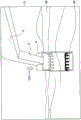
Fig. 2 is an explanatory view for explaining a direction in which the attachment of the hydraulic excavator shown in fig. 1 is projected.
Fig. 3 is a block diagram showing main functions of the hydraulic excavator shown in fig. 1.
Fig. 4 is a flowchart showing a flow of control processing for displaying a projected image of the distal attachment (bucket) and a surrounding image in a superimposed manner.
Fig. 5 is a diagram showing an example in which a projected image of the bucket, which is the remote attachment, is expressed in shades of color on a screen of the display device of the hydraulic excavator.
Fig. 6 is a diagram showing an example in which a screen of a display device in hydraulic shearing equipment as construction equipment according to embodiment 2 of the present invention represents a projected image of hydraulic shearing as remote auxiliary equipment in shades of color.
Fig. 7 is an explanatory view enlarging a portion a of fig. 6.
Fig. 8 is a block diagram showing the main functions of the hydraulic-shear heavy machine shown in fig. 6.
Fig. 9 is a flowchart showing a flow of control processing for displaying a projected image of the remote attachment (hydraulic scissors) and a surrounding image in a superimposed manner.
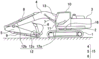
Fig. 10 is a side view showing a schematic configuration of a hydraulic excavator as a construction machine according to embodiment 3 of the present invention.
Fig. 11 is a block diagram showing main functions of the hydraulic excavator shown in fig. 10.
Fig. 12 is a side view showing a schematic configuration of a hydraulic excavator as a construction machine according to embodiment 4 of the present invention.
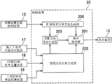
Fig. 13 is a block diagram showing main functions of a hydraulic excavator as a construction machine according to embodiment 5 of the present invention.
Fig. 14 is a block diagram showing main functions of a hydraulic excavator as a construction machine according to embodiment 6 of the present invention.
Detailed Description
Embodiments of the present invention will be described below with reference to the drawings. In all the drawings for describing the embodiments of the present invention, the same or related reference numerals are attached to the portions having the same functions, and the overlapping description is omitted. In the following embodiments, the same or similar portions will not be described in principle unless otherwise required.
(embodiment mode 1)
Fig. 1 is a side view showing a schematic configuration of a hydraulic excavator as a construction machine according to embodiment 1 of the present invention. Fig. 2 is an explanatory diagram for explaining a direction in which the attachment 15 of the hydraulic excavator shown in fig. 1 is projected. Fig. 3 is a block diagram showing main functions of the hydraulic excavator shown in fig. 1. Fig. 4 is a flowchart showing a flow of control processing for displaying a projected image of the bucket 6 as the distal attachment in the attachment 15 shown in fig. 1 and a surrounding image in a superimposed manner. Fig. 5 is a view showing an example in which a projected image of the bucket as the distal end attachment is expressed by shading in color on a screen of the display device of the hydraulic excavator.
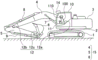
As shown in fig. 1, the hydraulic excavator includes: a lower traveling body 1; an upper revolving structure 3 rotatably mounted on the lower traveling structure 1; and an attachment 15 attached to the upper slewing body 3. The upper slewing body 3 is mounted on the lower traveling body 1 via a slewing mechanism 2. The attachment 15 includes a boom 4, an arm 5, and a bucket 6 (an example of a remote attachment). The boom 4 is attached to the upper slewing body 3, the arm 5 is attached to the distal end of the boom 4, and the bucket 6 is attached to the distal end of the arm 5. The boom 4, the arm 5, and the bucket 6 are hydraulically driven by a boom cylinder 7, an arm cylinder 8, and a bucket cylinder 9, respectively. Further, the upper revolving structure 3 is provided with a cab 10 on which a power source such as an engine is mounted.
The hydraulic excavator further includes an attachment state detection device 12 that detects a state of the attachment 15 (step S1 shown in fig. 4). The attachment state detection device 12 is mounted on, for example, the attachment 15 and the upper slewing body 3.
The attachment state detection device 12 is, for example, a sensor for acquiring information on the state of an attachment 15 of the hydraulic excavator. In the present embodiment, the accessory device state detection device 12 includes: a boom angle sensor 12a that detects the inclination of the boom 4 with respect to the upper slewing body 3; an arm angle sensor 12b that detects the inclination of the arm 5 with respect to the boom 4; and a bucket angle sensor 12c that detects the tilt of the bucket 6 with respect to the arm 5. In the present embodiment, the attachment state detection device 12 includes the above-described angle sensor, but is not necessarily limited to such a configuration. The attachment state detection device 12 may be replaced with at least one of the following 6 types of configurations, for example. The greater the number of devices that can be combined in the following 6 configurations, the greater the accuracy of detecting information about the state of the attachment 15.
1. Depth sensor capable of obtaining three-dimensional image together with distance to object (attachment)
2. A combination of the depth sensor and a gyro sensor provided at the distal end of the bucket 6
3. A combination of the depth sensor, the gyro sensor, and an AR mark (AR: Augmented Reality) disposed at the distal end of the bucket 6 (AR mark is an image of a predetermined pattern as a marker for specifying a position where additional information is displayed in an AR system)
4. Stereo camera
5. Combination of the stereo camera and the gyro sensor
6. Combination of the stereo camera, the gyro sensor and the AR mark
As shown in fig. 1 and 3, the hydraulic excavator further includes a control device 20, a display device 13, and a peripheral shape detection device 14. The control device 20 and the display device 13 are disposed inside the cab 10, for example. Further, the surrounding shape detection device 14 is provided, for example, on the top of the cab 10.
The peripheral shape detection device 14 is a device capable of detecting the three-dimensional shape of the peripheral work area in front of the hydraulic excavator (for example, step S3 shown in fig. 4). The surrounding work area is a work target (work site) located around the construction machine. The three-dimensional shape is also referred to as a "surrounding shape" in the following description.
The display device 13 may be, for example, a transparent head-up display (hereinafter also referred to as "transparent HUD"). The transparent HUD is provided, for example, on the inner side of a windshield 11 disposed in front of the cab 10 (also referred to as "front side in the cab 10"). The transparent HUD as an example of the display device 13 is not necessarily independent of the windshield 11, and may be integrated with the windshield 11. The display device 13 may be a display other than the transparent HUD.
The peripheral shape detection device 14 may be, for example, a range image sensor (range image camera) capable of acquiring a range image having range information for each pixel. Examples of the distance image sensor include a TOF type three-dimensional distance image sensor (for example, manufactured by ottas corporation) which is configured by a high-speed light source of a near-infrared LED and a CMOS image sensor and is capable of detecting a three-dimensional shape of a surrounding work area (TOF: Time of Flight). The peripheral shape detection device 14 may be a device other than the distance image sensor.
The main functional blocks shown in fig. 3 are constituted by an attachment state detection device 12, a display device 13, a peripheral shape detection device 14, a projection direction instruction input device 19, and a control device 20.
The projection direction instruction input device 19 has an input function of receiving an input by an operator. Specifically, for example, the projection direction instruction input device 19 has a touch panel. As shown in fig. 2, for example, the display screen of the touch panel displays a side surface of the hydraulic excavator and a plurality of arrows, specifically, for example, 8 arrows, indicating a direction in which the attachment 15 of the hydraulic excavator is projected (hereinafter, referred to as a "projection direction"). Therefore, the operator can input a desired projection direction by selecting (clicking or touching) any one of the plurality of arrows displayed on the display screen. As shown in step S5a shown in fig. 4, the control device 20 generates projection direction information based on input information about the projection direction input by the operator.
In the present embodiment, the projection direction instruction input device 19 is separate from the display device 13 as a separate device, but is not necessarily limited thereto. For example, in the case where the display screen of the display device 13 is configured by a touch panel, the display device 13 may have an input function of the projection direction instruction input device 19, and in this case, the projection direction instruction input device 19 may be omitted. In the present embodiment, the operator manually selects and inputs the projection direction, and the control device 20 generates the projection direction information based on the input information on the projection direction, but the present invention is not limited to this. For example, as in embodiment 2 described later, the control device 20 may automatically generate the projection direction information without input from the operator.
The control device 20 is a computer provided with a CPU, RAM, ROM, and the like, for example. Specifically, the control device 20 includes the functions of the attachment position information generation unit 200, the display control unit 201, and the peripheral shape information generation unit 202.
As shown in step S2 of fig. 4, the accessory position information generating unit 200 generates information (accessory position information) regarding the position of the accessory 15 based on the state of the accessory 15 detected by the accessory state detecting device 12.
Specifically, when the attachment state detection device 12 includes the boom angle sensor 12a, the arm angle sensor 12b, and the bucket angle sensor 12c, the attachment position information generation unit 200 can calculate the position of the attachment 15 based on the signals detected by the sensors 12a, 12b, and 12e, and therefore the attachment position information generation unit 200 can calculate the position of the remote attachment (bucket 6).
As shown in step S4 in fig. 4, the peripheral shape information generating unit 202 generates three-dimensional shape information (peripheral shape information) of the peripheral work region based on the three-dimensional shape (peripheral shape) of the peripheral work region detected by the peripheral shape detecting device 14. Specifically, the peripheral shape information generation unit 202 can calculate relative positions (coordinates) between the peripheral shape detection device 14 provided in the upper revolving structure 3 and a plurality of objects existing in the peripheral area. Examples of the plurality of objects include a foundation, a building, another vehicle, and an operator. By providing the hydraulic excavator with the peripheral shape detection device 14 and the peripheral shape information generation unit 202, it is possible to provide a system capable of acquiring the peripheral shape information even if the control device 20 does not store the peripheral shape information as data in advance.
The display control unit 201 generates the accessory-related information based on the accessory position information generated by the accessory position information generating unit 200 and the peripheral shape information detected by the peripheral shape detecting device 14, and controls the display device 13 to display the accessory-related information (step S9 shown in fig. 4).
Programs corresponding to the functional elements of the accessory position information generating unit 200, the display control unit 201, and the peripheral shape information generating unit 202 are read from the ROM and loaded into the RAM, and the CPU executes processing corresponding to the functional elements.
The accessory-related information is information corresponding to an image in which a surrounding image corresponding to the three-dimensional shape of the surrounding work area and a projected image in which an image corresponding to the remote accessory is projected onto the surrounding image in a projection direction described later are superimposed.
The display control unit 201 can calculate the position of the distal attachment and the relative positions (coordinates) of the plurality of objects present in the peripheral area based on the position (coordinates) of the distal attachment calculated by the attachment position information generating unit 200 and the relative positions (coordinates) of the peripheral shape detecting device 14 and the plurality of objects present in the peripheral area calculated by the peripheral shape information generating unit 202. The display control unit 201 may generate the surrounding image based on the three-dimensional shape information, and may generate the projected image based on the attachment position information and the three-dimensional shape information. Therefore, the display control section 201 can generate the accessory-related information based on the accessory position information and the three-dimensional shape information. Further, the display control unit 201 generates an image corresponding to the remote attachment based on shape information that is information on the shape of the remote attachment. The shape information of the remote attachment is stored in advance in the storage unit of the control device 20.
Therefore, in the present embodiment, the attachment-related information is calculated based on the shape information of the remote attachment, the attachment position information, and the three-dimensional shape information.
The projection direction is an arbitrarily set direction (arbitrary direction) or a direction set based on a predetermined condition. The arbitrary direction is a direction arbitrarily set by an operator from various directions in a three-dimensional space. Specifically, the arbitrary direction is a direction arbitrarily selected and set by the operator from among a plurality of directions indicated by a plurality of arrows (specifically, 8 arrows, for example) shown in fig. 2, for example. The direction set based on the predetermined condition is, for example, a direction set by the control device 20 based on the predetermined condition. The predetermined condition may be, for example, a condition set in advance and stored in the control device 20, or a condition set and stored in the control device 20 based on information input to the control device 20 by an operator and various sensors before and during the operation of the hydraulic excavator.
As described above, by adopting the configuration in which the attachment related information corresponding to the image in which the projected image is superimposed on the surrounding image is displayed on the display device 13, the operator can easily and intuitively grasp the approach of the distal attachment to the target position (for example, the bucket 6) in the surrounding work area, specifically, on the ground having undulations in the work site that is the work target. As described above, the hydraulic excavator according to the present embodiment has a guidance function for facilitating the work of the operator.
As described above, the attachment related information is information corresponding to an image in which a projected image of the distal attachment (bucket 6) is superimposed on a surrounding image corresponding to the three-dimensional shape of the surrounding work area. The projected image includes the distance information calculated (generated) by the display control unit 201 of the control device 20. As described above, the display control unit 201 can calculate the relative positions (coordinates) of the position of the remote attachment and the plurality of objects existing in the surrounding area. Therefore, the display control unit 201 can generate the distance information based on the calculated relative position. The distance information is information on the distance between the bucket 6 and a portion of the object existing in the peripheral work area corresponding to the portion where the peripheral image and the projected image overlap each other (step S6 shown in fig. 4).
The projected image is an image calculated (generated) by the display control unit 201, and is a projected image expressed by the shading of the color based on the distance information (step S7 in fig. 4).
The projected image expressed by the shading of the color will be described in more detail with reference to fig. 5. The image displayed on the screen of the display device 13 shown in fig. 5 includes an image corresponding to the three-dimensional shape of the work site (e.g., a rough land) as the surrounding work area, that is, the surrounding image 30, the projected image 40 expressed by the shade of color (e.g., black and white shade), and the image of the bucket 6. In fig. 5, the projection direction indicated by an arrow is set to a direction in which the bucket 6 approaches the ground, which is an example of a target position of the work site (a rough ground), for example.
The projected image 40 is expressed, for example, by black and white shading, based on distance information about the distance between the bucket 6 and a portion of the ground of the work site corresponding to the portion where the surrounding image 30 and the projected image 40 overlap each other. For example, the shadowgraph image 40 is represented as: the smaller the distance between the ground and the bucket 6, i.e. the closer the two are, the denser the color becomes.
The display control unit 201 calculates a position for displaying the projected image 40 and the surrounding image 30 in a superimposed manner based on the projection direction, the shape information of the distal end attachment, the attachment position information, and the three-dimensional shape information (step S8 shown in fig. 4). Then, as shown in fig. 5, the display control unit 201 displays the projected image 40 on the display device 13 in a superimposed manner on the peripheral image 30 (step S9 shown in fig. 4).
With the above-described configuration according to the present embodiment, the operator can more easily and intuitively grasp the approach of the distal attachment (the bucket 6 in the present embodiment) to the target position in the surrounding work area, specifically, for example, in the target work site, that is, in the rough ground. Thus, the hydraulic excavator according to the present embodiment has a guidance function for making it easier for the operator to perform work. Further, in some cases, a structure or an electric wire (an example of an object) may be present in a direction obliquely above and forward of the construction machine (hydraulic excavator in the present embodiment) or above the construction machine. In this case, information on the distance between the structure or the electric wire and the attachment 15 of the hydraulic excavator may be displayed on the display device 13. In this case, the operator can easily recognize the distance between the remote attachment and the object, and can easily avoid contact between the construction machine (hydraulic excavator) and the structure or the electric wire. Accordingly, the visual burden on the operator is also reduced.
In the present embodiment, the projected image 40 is represented by black and white shading based on the distance information, and is represented by a mode in which the color is darker as the two are closer to each other, but the present invention is not limited to this. For example, the projected image 40 may be expressed by a shade of a color other than black and white, and expressed in such a manner that the color becomes darker as the two are closer to each other. The projected image 40 may be expressed by a plurality of types of colors set according to the degree of proximity between the two. In addition, the projected image 40 may be represented by a marker that can identify the degree of proximity of the two.
In the present embodiment, since the display device 13 is a transparent HUD provided on the front side in the cab 10, the operator does not need to move the line of sight (viewpoint) from the work site to be operated when the operator effectively uses the tutoring function. This can suppress a reduction in work efficiency. In the present embodiment, since the TOF three-dimensional range image sensor capable of detecting the three-dimensional shape of the peripheral work area is used as the peripheral shape detection device 14, the peripheral shape detection device 14 can simultaneously detect the three-dimensional shape of the peripheral work area and the position of the attachment. Therefore, in the present embodiment, the attachment position information generating unit 200 may generate the attachment position information based on the information on the position of the attachment detected by the peripheral shape detecting device 14. In this case, the peripheral shape detection device 14 also functions as an attachment state detection device. That is, the attachment state detection device constituted by the peripheral shape detection device 14 has both a function of detecting the state of the attachment and a function of detecting the three-dimensional shape of the peripheral work area. In this case, the attachment state detection device 12 shown in fig. 1 may be omitted.
(embodiment mode 2)
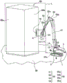
Fig. 6 is a view showing an example in which a projected image of a hydraulic shears serving as a remote sub-equipment is expressed by shading of colors on a screen of a display device of a hydraulic shears for building demolition which is a construction machine according to embodiment 2 of the present invention. Fig. 7 is an explanatory view enlarging a portion a of fig. 6. Fig. 8 is a block diagram showing the main functions of the hydraulic-shear heavy machine shown in fig. 6. Fig. 9 is a flowchart showing a flow of control processing for displaying a projected image of the remote attachment (hydraulic scissors) superimposed on a surrounding image.
As shown in fig. 6, the hydraulic heavy machinery includes a lower traveling structure 1, an upper revolving structure 3, and an attachment 50 attached to the upper revolving structure 3. The attachment 50 includes a boom 51, a first arm 52, a second arm 53, and a hydraulic shear 54 (an example of a remote attachment).
The hydraulic shearing machine further includes an attachment state detection device 55 that detects a state of the attachment 50. The attachment state detection device 55 is mounted on the attachment 50, for example. The attachment state detection device 55 in the hydraulic shearing heavy machine has the same function as the attachment state detection device 12 shown in fig. 1 to 3.
The attachment state detection device 55 is, for example, a sensor for acquiring information on the state of the attachment 50 of the hydraulic shears for demolishing a building. In the present embodiment, the attachment state detection device 55 includes: a boom angle sensor 55a that detects the inclination of the boom 51 with respect to the upper slewing body 3; a first arm angle sensor 55b that detects the inclination of the first arm 52 with respect to the boom 51; a second arm angle sensor 55c that detects the inclination of the second arm 53 with respect to the first arm 52; and a hydraulic shear angle sensor 55d that detects the inclination of the hydraulic shear 54 with respect to the second arm 53.
The image displayed on the screen of the display device 13 is an image of an area surrounded by a broken line L in fig. 6, and includes a peripheral image 60, a projected image 70, and an image of the hydraulic shears 54, which are images corresponding to the three-dimensional shape of the area. The surrounding image 60 is an image corresponding to the three-dimensional shape of the surrounding work area, and in the present embodiment includes an image corresponding to a building (an example of an object) built in the work site to be worked. In fig. 6, a building demolition hydraulic shearing machine is disposed on the ground 90, and the building is built on the ground 90.
As shown in fig. 8, the control device 20 of the hydraulic shearing machine includes a projection direction information generating unit 203. The projection direction information generating unit 203 automatically generates projection direction information based on the three-dimensional shape information and the attachment position information (step 5b shown in fig. 9). The three-dimensional shape information is information generated by the peripheral shape information generation unit 202, is information on the three-dimensional shape of the peripheral work area, and includes a three-dimensional shape corresponding to a building. The attachment position information is information generated by the attachment position information generating unit 200, and includes position information on the position of at least the distal attachment (e.g., the hydraulic shears 54) in the attachment 50. The following describes a more detailed function of the projection direction information generating unit 203.
The control device 20 can determine whether or not an object is present in the vicinity of the distal attachment (hydraulic shears 54) based on the three-dimensional shape information (surrounding shape information) and the attachment position information. In the specific example shown in fig. 6, the control device 20 determines that a wall surface 60b of a building exists in the vicinity of the hydraulic shears 54, and the shortest distance between the hydraulic shears 54 and the wall surface 60b of the building is X as shown in fig. 7.
The projection direction information generating unit 203 stores a preset reference point 54a of the remote accessory. In the present embodiment, the reference point 54a is set at the center of the hydraulic shears 54, for example, but is not limited thereto, and may be set at a position offset from the center.
The projection direction information generating unit 203 stores a plurality of preset directions. Each of the plurality of directions is a direction based on a predetermined specific portion of the hydraulic shearing machine for demolishing a building. The specific portion is set, for example, at any portion in the main body of the hydraulic shearing and heavy equipment. Examples of the main body of the hydraulic shearing machine include the upper slewing body 3 and the lower traveling body 1. In the present embodiment, the plurality of directions include, for example, the front, rear, upper, and lower directions indicated by the black 4 arrows shown in fig. 6. The projection direction information generating unit 203 determines which of the plurality of directions (front, rear, upper, and lower) the wall surface 60b of the building and the reference point 54a are located with respect to the specific portion, based on the attachment position information and the three-dimensional shape information, and automatically generates the direction of the determination result as projection direction information. In the case of the present embodiment shown in fig. 6 and 7, the projection direction information is shown in front by white arrows in fig. 6. In the case of the configuration according to the present embodiment, the projection direction information generating unit 203 can automatically generate appropriate projection direction information (projection direction information in any direction) based on the peripheral shape information and the attachment position information, in addition to the case where the projection direction information is in front as described above.
The attachment related information in the present embodiment is calculated based on the shape information of the remote attachment 54, the attachment position information, and the three-dimensional shape information. The attachment related information is information corresponding to an image in which the surrounding image 60 and the projected image 70 are superimposed, the surrounding image 60 is an image corresponding to the three-dimensional shape of the surrounding work area, and the projected image 70 is an image in which the image of the corresponding hydraulic shears 54 is projected onto the surrounding image 60 in the projection direction. The surrounding image 60 includes an image corresponding to a building existing in the surrounding work area. In the present embodiment, the projection direction is not limited to the forward direction, and the projection direction information generation unit 203 can automatically generate appropriate projection direction information based on the peripheral shape information and the accessory position information.
The attachment related information is information corresponding to an image in which the projected image 70 of the distal attachment (hydraulic shears 54) is superimposed on the surrounding image 60 corresponding to the three-dimensional shape of the surrounding work area. The projected image 70 includes distance information calculated (generated) by the display control unit 201 of the control device 20. The distance information is information on the distance between the hydraulic shears 54 and a portion of the object existing in the peripheral work area corresponding to the portion where the peripheral image 60 and the projected image 70 overlap.
The projected image 70 is an image calculated (generated) by the display control unit 201, and is a projected image expressed by the shade of color based on the distance information.
The projected image 70 expressed by the shading of the color will be described in more detail with reference to fig. 6. The projected image 70 included in the image displayed on the screen of the display device 13 shown in fig. 6 is a projected image expressed by the shade of color, for example, a projected image expressed by the shade of black. In fig. 6, the projection direction (the projection direction indicated by a white arrow) may be set, for example, to a direction in which the hydraulic shears 54 approach a part of the wall surface 6b that is a target position of a building existing at the work site.
The projected image 70 is expressed, for example, by black and white shading, based on distance information about the distance between the hydraulic shears 54 and a portion corresponding to a portion of the building existing in the work site where the surrounding image 60 and the projected image 70 overlap each other. For example, the projected image 70 is expressed such that the closer the building is to the hydraulic shears 54, the darker the color is.
The display control unit 201 calculates a position for displaying the projected image 70 superimposed on the surrounding image 60 based on the projection direction, the shape information of the attachment, the position information of the attachment, and the three-dimensional shape information. As shown in fig. 6, the display control unit 201 displays the projected image 70 on the display device 13 in a superimposed manner on the surrounding image 60.
With the above-described configuration according to the present embodiment, the operator can more easily and intuitively grasp the approach of the remote attachment (in the present embodiment, the hydraulic shears 54) to the target position (a part of the wall surface) in the surrounding work area, specifically, in a building existing in the work site as the target, for example. Accordingly, the hydraulic shears heavy machine according to the present embodiment has a guidance function for making it easier for the operator to perform work. In the present embodiment, the distal attachment is the hydraulic shears 54, but in the present invention, the distal attachment may be various types of distal attachments other than the hydraulic shears 54.
In the present embodiment, the projection direction information generating unit 203 automatically generates projection direction information regarding the projection direction based on the peripheral shape information and the attachment position information, but is not limited thereto. For example, the projection direction information generating unit 203 may automatically generate projection direction information in which the moving direction of a specific portion in the attachment 50, specifically, for example, the moving direction of the distal end of the distal-end attachment is set as the projection direction. Specifically, the attachment position information generating unit 200 may generate attachment position information at a specific time (for example, the current time) and attachment position information before a predetermined time of the specific time, calculate the moving direction of the distal end of the distal-end attachment (hydraulic shears 54) based on the attachment position information, and generate projection direction information in which the moving direction is set as the projection direction. When the operation of the distal end of the distal attachment (hydraulic shears 54) is stopped, the projection direction information generating unit 203 may generate projection direction information that is calculated a predetermined time before a specific time (for example, the current time). The specific portion of the attachment 50 is not limited to the distal end of the hydraulic shears 54, and may be set to, for example, the toe of the bucket 6 or the distal end of the arm 5 (for example, the position indicated by the reference numeral 12 c) as shown in fig. 1, and the projection direction information generating unit 203 may calculate the movement direction of the set specific portion and generate projection direction information in which the movement direction is set to the projection direction.
(embodiment mode 3)
Fig. 10 is a side view showing a schematic configuration of a hydraulic excavator as a construction machine according to embodiment 3 of the present invention, and fig. 11 is a block diagram showing main functions of the hydraulic excavator shown in fig. 10. In embodiment 3, the peripheral shape detection device 14 provided at the ceiling portion of the cab 10 shown in fig. 1 in embodiment 1 is omitted. In embodiment 3, the function of the peripheral shape detection device 14 is realized by the following three components shown in fig. 10 and 11 instead of the peripheral shape detection device 14. The first component is a storage device 17 that stores three-dimensional shape information (three-dimensional shape data of a construction site) of a surrounding work area prepared by imaging with an imaging device such as an unmanned aerial vehicle in advance. The second component is a receiver 18 capable of receiving data relating to a satellite positioning system such as GPS and GSNN, and the receiver 18 is capable of acquiring the own vehicle position information by receiving the data relating to the satellite positioning system. The third component is an upper slewing body state detection device 16. The upper slewing body state detection device 16 is provided in the slewing mechanism 2, for example. The upper slewing body state detecting device 16 is constituted by, for example, an orientation sensor for detecting a direction in which the upper slewing body 3 is oriented. The surrounding shape information generating unit 202 generates three-dimensional shape information (surrounding shape information) of a surrounding work area based on the three-dimensional shape data stored in the storage device 17, the vehicle position information acquired by the receiver 18, and information on the orientation of the upper revolving structure 3 detected by the upper revolving structure state detecting device 16.
In the present embodiment, the function of the peripheral shape detecting device 14 shown in fig. 1 is realized by the storage device 17, the receiver 18, and the upper slewing body state detecting device 16, but the present invention is not limited to these. For example, the second component and the third component among the three components may be replaced with other components. As such another component, for example, a receiver capable of receiving data relating to a satellite positioning system can be given. In this case, the function of the peripheral shape detection device 14 shown in fig. 1 is realized by a storage device 17 that stores three-dimensional shape information (three-dimensional shape data of a construction site) of a peripheral work area prepared by imaging with an imaging device such as an unmanned aerial vehicle in advance, a receiver 18 that can acquire vehicle position information by receiving data relating to the satellite positioning system, and a receiver that can acquire information relating to the orientation of the upper revolving structure 3 by receiving data relating to the satellite positioning system. That is, the functions of the second component and the third component can be realized by a plurality of receivers capable of receiving data relating to the satellite positioning system.
(embodiment mode 4)
Fig. 12 is a side view showing a schematic configuration of a hydraulic excavator as a construction machine according to embodiment 4 of the present invention. The display device in embodiment 4 is different from the display device 13 provided on the front side in the cab 10 shown in fig. 1 in embodiment 1. The display device 110 in embodiment 4 is configured by a glasses-type transparent head mounted display (glasses-type transparent HMD) worn by the operator 100 in the cab 10 shown in fig. 12.
In embodiment 4, as in the other embodiments described above, the operator can more easily and intuitively grasp the approach of the distal attachment (bucket 6) to the target position on the rough ground in the surrounding work area (specifically, the work site to be worked). As described above, the hydraulic excavator according to the present embodiment has a guidance function for facilitating the operation of the operator. Further, the hydraulic excavator according to embodiment 4 has an advantage that it is not necessary to provide a large transparent HUD on the front side in the cab 10 as in the display device 13 of embodiment 1.
Further, although the transparent HUD as the display device 13 described in embodiments 1 to 3 and the glasses-type transparent HMD as the display device 110 described in embodiment 4 are both display devices that are used in the cab 10, the display device according to the present invention is not necessarily present in the cab 10, and may be disposed outside the cab 10. For example, the display device may be constituted by a remote operation assistance monitor for an operator to remotely operate a hydraulic excavator (construction machine) using a remote operation device outside the cab 10. Details of the remote operation assistance monitor are described in embodiments 5 and 6 described later. In this case, the operator can easily and intuitively grasp the approach of the remote attachment to the target position in a rough ground, a building, or the like in the surrounding work area (specifically, a work site to be worked), and the hydraulic excavator has a guidance function for facilitating the operation of the operator. Further, when the operator effectively uses the guidance function, the operator does not need to move the viewpoint from the work site to be worked, and a reduction in work efficiency is suppressed. In addition, when the remote operation assistance monitor is used, the operator does not necessarily need to operate the construction machine at an actual work site, and can remotely operate the construction machine in a building in which the remote operation assistance monitor is set. This also has the effect of improving the degree of freedom of the place where the operator actually works.
(embodiment 5)
Fig. 13 is a block diagram showing main functions of a hydraulic excavator as a construction machine according to embodiment 5 of the present invention. The hydraulic excavator according to embodiment 5 is different from the hydraulic excavator according to embodiment 3 in that it has a remotely operable configuration, and is the same as the hydraulic excavator according to embodiment 3 in other points. In embodiment 5, the display device 120 is not disposed inside the cab 10 of the hydraulic excavator, but is disposed at a remote location outside the cab 10. The hydraulic excavator according to embodiment 5 includes a construction machine main body and a remote control unit.
As shown in fig. 13, the construction machine main body includes the control device 20, the attachment state detection device 12, the storage device 17, the receiver 18, the upper slewing body state detection device 16, and a transmission device 130. The remote operation unit includes a display device 120 and a receiving device 140. The control device 20 and the display device 120 are mechanically separated. The control device 20 and the display device 120 are connected to each other by wireless communication. The display device 120 according to embodiment 5 is a monitor for remote operation assistance for an operator to remotely operate a hydraulic excavator (construction machine) using a remote operation device outside the cab 10. Therefore, the features will be described in detail below, and the same reference numerals are attached to the same components as those in embodiment 3, and detailed description thereof will be omitted.
As shown in fig. 13, a display device 120 of a hydraulic excavator according to embodiment 5 is a monitor for remote operation assistance for remotely operating the hydraulic excavator (construction machine) outside the cab 10. The transmission device 130 is provided in a construction machine body (hydraulic excavator body), and a signal output from the display control unit 201 is input to the transmission device 130. The receiving device 140 is provided in the remote operation unit, and receives a signal from the transmitting device 130. The signal received by the receiving device 140 is input to the display device 120. The display device 120 displays an image related to the input signal.
The hydraulic excavator according to embodiment 5 is configured such that information similar to the attachment related information in embodiment 1 is transmitted from the transmission device 130 to the reception device 140 by wireless communication. Examples of the wireless communication include communication using radio waves such as communication using a cellular phone network and communication using a wireless LAN.
In embodiment 5, the attachment related information is generated in the construction machine main body in the hydraulic excavator. The accessory-related information is generated based on the accessory position information and the three-dimensional shape information. The accessory-related information is information corresponding to an image (accessory-related image) in which a surrounding image corresponding to the three-dimensional shape of the surrounding work area and a projected image projected in the projection direction are superimposed. The accessory-related information is transmitted to the display device 120 (the remote operation assistance monitor) of the remote operation unit via the transmission device 130 and the reception device 140. The display device 120 (the remote operation assistance monitor) displays the received image. Therefore, the equipment constituting the display device 120 (the remote operation assistance monitor) can be simplified.
(embodiment mode 6)
Fig. 14 is a block diagram showing main functions of a hydraulic excavator as a construction machine according to embodiment 6 of the present invention. The hydraulic excavator according to embodiment 6 is different from the hydraulic excavator according to embodiment 5 in that the control device 20 is not provided in the work machine main body but is provided in the remote operation unit, and is otherwise the same as the hydraulic excavator according to embodiment 5. In embodiment 6, the construction machine body includes an attachment state detection device 12, a storage device 17 that stores three-dimensional shape data of a construction site, a receiver 18 that can acquire vehicle position information by receiving data relating to a satellite positioning system such as a GPS, an upper revolving structure state detection device 16, and a transmission device 150. The remote operation unit includes a receiving device 160, the control device 20, and the display device 120. The attachment state detecting device 12, the storage device 17, the receiver 18, and the upper slewing body state detecting device 16 and the control device 20 are characterized in being mechanically separated and connected to each other by wireless communication. Therefore, the features will be described in detail below, and the same reference numerals are attached to the same components as those in embodiment 5, and detailed description thereof will be omitted.
As shown in fig. 14, the transmission device 150 is provided in a construction machine body (hydraulic excavator body), and attachment basic data regarding the state of the attachment detected by the attachment state detection device 12 and peripheral work area basic data that is a basis of the three-dimensional shape information of the peripheral work area are input to the transmission device 150. The peripheral work area basic data includes, for example: three-dimensional shape data stored in the construction site of the storage device 17; the location information of the vehicle received by the receiver 18; and information on the orientation of the upper slewing body 3 detected by the upper slewing body state detection device 16. The receiving device 160 is provided in a remote control unit, and receives the attachment base data and the peripheral work area base data transmitted from the transmitting device 150 by wireless communication.
The accessory device position information generating unit 200 generates accessory device position information based on the accessory device basic data received by the receiving device 160. The peripheral shape information generation unit 202 generates three-dimensional shape information of the peripheral work area based on the peripheral work area basic data received by the reception device 160. The display control unit 201 generates attachment related information based on the attachment position information and the three-dimensional shape information, and controls the display device 120 (the remote operation assistance monitor) to display the attachment related information.
With the configuration according to embodiment 6, the attachment related information is generated in the remote operation unit based on the attachment base data and the surrounding work area base data transmitted from the transmission device 150 provided in the construction machine main body (hydraulic excavator main body). Therefore, it is not necessary to mount a processing device for generating the image on a hydraulic excavator main body (construction machine main body) that generates vibration and impact more than the remote operation unit. Therefore, the structure of the hydraulic excavator main body (construction machine main body) can be simplified.
In embodiments 1 to 6, the accessory-related information is information corresponding to an image in which a surrounding image corresponding to the three-dimensional shape of the surrounding work area and a projected image in which an image corresponding to the remote accessory is projected onto the surrounding image in the projection direction are superimposed, but the present invention is not limited to this. For example, in addition to the image corresponding to the distal attachment (the bucket 6 and the hydraulic shears 54), an image corresponding to at least one member of the shape information of the boom 4, the arm 5, the boom 51, the first arm 52, and the second arm 53 is projected onto the surrounding image. That is, the accessory-related information according to the present invention may be information on an image projected on the surrounding image along the projection direction at least in correspondence with the image of the remote accessory.
The embodiments of the present invention have been described above, but these are merely specific examples, and the present invention is not particularly limited thereto, and the specific configurations and the like may be appropriately modified and designed. The operations and effects described in the embodiments of the present invention are merely the most suitable operations and effects produced by the present invention, and the operations and effects of the present invention are not limited to the operations and effects described in the embodiments of the present invention.
The present inventors have intensively studied how to realize a construction machine having a guidance function for allowing an operator to easily approach an attachment to a target position of a surrounding work area (a work site as a target). As a result, it was found that the object can be achieved by various configurations described below.
The construction machine of the present invention is provided with an attachment including a remote attachment. The construction machine includes: accessory device status detection means for detecting a status of the accessory device; an attachment position information generating unit that generates attachment position information as information on a position of an attachment based on the state of the attachment detected by the attachment state detecting device; a display device; and a display control unit that controls the display device to display attachment related information generated based on the attachment position information generated by the attachment position information generation unit and three-dimensional shape information that is information on a three-dimensional shape of a work area around the construction machine. The accessory-related information is information corresponding to an image in which a surrounding image corresponding to the three-dimensional shape of the surrounding work area and a projected image in which an image corresponding to the remote accessory is projected onto the surrounding image in an arbitrarily set projection direction or a projection direction set based on a predetermined condition are superimposed.
In this construction machine, since the display device displays the attachment related information corresponding to the image in which the peripheral image and the projected image are superimposed, the operator can perform an operation for bringing the remote attachment close to a target position in a peripheral work area (a work site as a target) while confirming the attachment related information displayed on the display device. Therefore, according to the present invention, it is possible to provide a construction machine having a guidance function for facilitating an operator's operation for bringing an attachment closer to the target position in the peripheral work area.
Specifically, the display control unit may calculate a relative position of the remote attachment with respect to an object existing in the peripheral work area based on the attachment position information and the three-dimensional shape information. Further, the display control unit may generate the surrounding image based on the three-dimensional shape information, and may generate the projected image in which the image corresponding to the remote attachment is projected onto the surrounding image in the projection direction based on the relative position, whereby the display control unit may generate an image (superimposed image) in which the surrounding image and the projected image are superimposed. Therefore, the display control unit can generate the accessory-related information based on the accessory position information and the three-dimensional shape information, and can perform control to display the accessory-related information on the display device.
In the construction machine, it is preferable that the projected image is expressed by a shade of color or a type of color corresponding to distance information regarding a distance between the remote attachment and a portion corresponding to a portion where the peripheral image and the projected image overlap, among objects existing in the peripheral work area.
In this configuration, the projection image is expressed by the shade of the color or the type of the color corresponding to the distance information. This makes it easy for the operator to intuitively recognize the distance information based on the shade of the color or the kind of the color.
Specifically, the display control unit calculates the relative position of the remote attachment with respect to the object existing in the peripheral work area based on the attachment position information and the three-dimensional shape information as described above. The display control unit may calculate a distance between the remote attachment and the portion of the object based on the relative position. Therefore, the display control unit can generate the projected image expressed by the shade of the color or the type of the color corresponding to the distance information based on the attachment position information and the three-dimensional shape information.
The construction machine preferably further comprises: a peripheral shape detection device that detects the three-dimensional shape of the peripheral work area; and a peripheral shape information generating unit that generates the three-dimensional shape information of the peripheral work region based on the three-dimensional shape of the peripheral work region detected by the peripheral shape detecting device.
In this configuration, since the peripheral shape information generating unit generates the three-dimensional shape information based on the three-dimensional shape of the peripheral work area detected by the peripheral shape detecting device, the construction machine does not need to store the three-dimensional shape information of the peripheral work area of the work site to be worked as data in advance before starting the work.
In the construction machine, the peripheral shape detection device may be configured to be able to detect a shape of the distal end attachment.
In this configuration, even when the remote attachment (first remote attachment) is replaced with another remote attachment (second remote attachment), the construction machine can acquire the shape information of the second remote attachment based on the shape of the second remote attachment detected by the peripheral shape detection device. This enables the shape information of the remote attachment to be updated to the latest information even in the case where the remote attachment is replaced. In this configuration, the peripheral shape detection device has both a function of detecting the three-dimensional shape of the peripheral working area and a function of detecting the shape of the distal attachment, and therefore, it is possible to suppress the construction of the construction machine from becoming complicated.
In the construction machine, the attachment state detection device may be configured to be able to detect the three-dimensional shape of the surrounding work area.
In this configuration, since the attachment state detection device has both a function of detecting the state of the attachment and a function of detecting the three-dimensional shape of the peripheral work area, a device for detecting the three-dimensional shape of the peripheral work area (for example, the peripheral shape detection device described above) can be omitted.
In the construction machine, the display device may be a transparent head-up display provided on a front side in a cab.
In this configuration, since the display device is a transparent head-up display, the region in which the accessory-related information is displayed can be set relatively freely as compared with a case where the display device is, for example, a liquid crystal display, and it is possible to suppress the view of the operator from being blocked by the display device.
In the construction machine, the display device may be a transparent head-mounted display that can be worn by an operator in the cab.
In this configuration, since the display device is a head-mounted display, it is possible to suppress the operator's view from being blocked, compared to a case where the display device is, for example, a liquid crystal display. In this configuration, since the head-mounted display is transparent, the visual information obtained by the operator does not need to be limited to the information displayed on the head-mounted display, but includes information that acts on the visual sense of the operator through the head-mounted display. Therefore, the operator can perform a switch operation for operating a switch in the cab, for example, without the visual field being obstructed by the head-mounted display.
The construction machine may further include: a transmission device provided in a construction machine body including the attachment; and a receiving device provided in a remote operation unit for remotely operating the construction machine main body outside a cab of the construction machine main body, wherein the display device is a remote operation support monitor provided in the remote operation unit, a signal related to the attachment related information output from the display control unit is transmitted from the transmitting device to the receiving device by wireless communication, and the remote operation support monitor displays the attachment related information based on the signal received by the receiving device.
In this configuration, the operator must go to the actual work site and can remotely operate the construction machine at the remote operation unit provided at a remote location apart from the work site.
The construction machine may further include: a transmission device that is provided in a construction machine main body including the attachment, and to which attachment base data regarding a state of the attachment detected by the attachment state detection device and peripheral work area base data that is a base of the three-dimensional shape information of the peripheral work area are input; a receiving device provided in a remote operation unit for remotely operating the construction machine main body outside a cab of the construction machine main body, the receiving device receiving the attachment basic data and the surrounding work area basic data transmitted from the transmitting device by wireless communication; and a peripheral shape information generating unit that is provided in the remote operation unit and generates the three-dimensional shape information of the peripheral work area based on the peripheral work area basic data received by the receiving device, wherein the display device is a remote operation assistance monitor provided in the remote operation unit, the attachment position information generating unit is provided in the remote operation unit and generates attachment position information based on the attachment basic data received by the receiving device, and the display control unit is provided in the remote operation unit and controls the remote operation assistance monitor to display the attachment related information.
In this configuration, the operator must go to the actual work site and can remotely operate the construction machine at the remote operation unit provided at a remote location apart from the work site. In this configuration, since the attachment position information generating unit and the peripheral shape information generating unit are provided in the remote operation unit, the attachment position information and the three-dimensional shape information are generated in the remote operation unit. That is, in this configuration, it is not necessary to mount a processing device that configures the attachment position information generating unit and the peripheral shape information generating unit on the main body of the construction machine where vibration and impact occur frequently.
Claims (9)
1. A construction machine having an attachment including a remote attachment, comprising:
accessory device status detection means for detecting a status of the accessory device;
an attachment position information generating unit that generates attachment position information as information on a position of an attachment based on the state of the attachment detected by the attachment state detecting device;
a display device; and the number of the first and second groups,
a display control unit that controls the display device to display attachment related information generated based on the attachment position information generated by the attachment position information generation unit and three-dimensional shape information that is information on a three-dimensional shape of a surrounding work area of the construction machine,
The accessory-related information is information corresponding to an image in which a surrounding image corresponding to the three-dimensional shape of the surrounding work area and a projected image in which an image corresponding to the remote accessory is projected onto the surrounding image in an arbitrarily set projection direction or a projection direction set based on a predetermined condition are superimposed.
2. The work machine of claim 1,
the projected image is expressed by a shade of color or a type of color corresponding to distance information regarding a distance between the remote attachment and a portion corresponding to a portion where the peripheral image overlaps the projected image among the objects existing in the peripheral work area.
3. A working machine according to claim 1 or 2, characterized by further comprising:
a peripheral shape detection device that detects the three-dimensional shape of the peripheral work area; and the number of the first and second groups,
a peripheral shape information generating unit configured to generate the three-dimensional shape information of the peripheral work region based on the three-dimensional shape of the peripheral work region detected by the peripheral shape detecting device.
4. A working machine according to claim 3,
the peripheral shape detection means is capable of detecting the shape of the distal attachment.
5. A working machine according to claim 1 or 2,
the attachment state detection device is capable of detecting the three-dimensional shape of the surrounding work area.
6. A working machine according to any of claims 1-5,
the display device is a front-side transparent head-up display disposed in the cab.
7. A working machine according to any of claims 1-5,
the display device is a transparent head-mounted display that can be worn by an operator in the cab.
8. A working machine according to any of claims 1-5, characterized by further comprising:
a transmission device provided in a construction machine body including the attachment; and the number of the first and second groups,
a receiving device provided in a remote operation unit for remotely operating the construction machine main body outside a cab of the construction machine main body,
the display device is a monitor for remote operation assistance provided in the remote operation unit,
The display control unit outputs a signal related to the accessory device-related information from the transmitter to the receiver via wireless communication, and the remote operation assistance monitor displays the accessory device-related information based on the signal received by the receiver.
9. A working machine according to claim 1 or 2, characterized by further comprising:
a transmission device that is provided in a construction machine main body including the attachment, and to which attachment base data regarding a state of the attachment detected by the attachment state detection device and peripheral work area base data that is a base of the three-dimensional shape information of the peripheral work area are input;
a receiving device provided in a remote operation unit for remotely operating the construction machine main body outside a cab of the construction machine main body, the receiving device receiving the attachment basic data and the surrounding work area basic data transmitted from the transmitting device by wireless communication; and the number of the first and second groups,
a peripheral shape information generating section provided in the remote operation section, and generating the three-dimensional shape information of the peripheral work area based on the peripheral work area basic data received by the receiving device,
The display device is a monitor for remote operation assistance provided in the remote operation unit,
the accessory device position information generating section is provided in the remote operation section, generates accessory device position information based on the accessory device basic data received by the receiving device,
the display control unit is provided in the remote operation unit, and controls the remote operation support monitor to display the accessory-related information.
Applications Claiming Priority (3)
| Application Number | Priority Date | Filing Date | Title |
|---|---|---|---|
| JP2018-061613 | 2018-03-28 | ||
| JP2018061613A JP7087545B2 (en) | 2018-03-28 | 2018-03-28 | Construction machinery |
| PCT/JP2019/013304 WO2019189430A1 (en) | 2018-03-28 | 2019-03-27 | Construction machine |
Publications (1)
| Publication Number | Publication Date |
|---|---|
| CN111868340A true CN111868340A (en) | 2020-10-30 |
Family
ID=68059095
Family Applications (1)
| Application Number | Title | Priority Date | Filing Date |
|---|---|---|---|
| CN201980020549.8A Pending CN111868340A (en) | 2018-03-28 | 2019-03-27 | Construction machine |
Country Status (5)
| Country | Link |
|---|---|
| US (1) | US11421404B2 (en) |
| EP (1) | EP3754122A4 (en) |
| JP (1) | JP7087545B2 (en) |
| CN (1) | CN111868340A (en) |
| WO (1) | WO2019189430A1 (en) |
Families Citing this family (10)
| Publication number | Priority date | Publication date | Assignee | Title |
|---|---|---|---|---|
| JP7080750B2 (en) * | 2018-06-29 | 2022-06-06 | 株式会社小松製作所 | Display control system, remote control system, display control device, and display control method |
| JP7285051B2 (en) * | 2018-06-29 | 2023-06-01 | 株式会社小松製作所 | Display control device and display control method |
| JP2021070922A (en) * | 2019-10-29 | 2021-05-06 | 住友重機械工業株式会社 | Shovel |
| KR102415420B1 (en) * | 2019-11-29 | 2022-07-04 | 한국생산기술연구원 | System for measuring the position of the bucket of the excavator and method for measuring the position of the bucket using the same |
| JP7452038B2 (en) * | 2020-01-30 | 2024-03-19 | コベルコ建機株式会社 | Work support system |
| JP2021130973A (en) * | 2020-02-20 | 2021-09-09 | 株式会社フジタ | Information presentation system |
| JP2021143541A (en) * | 2020-03-13 | 2021-09-24 | コベルコ建機株式会社 | Operation support server, operation support method |
| KR102417984B1 (en) * | 2020-05-11 | 2022-07-08 | 한국생산기술연구원 | System to assist the driver of the excavator and method of controlling the excavator using the same |
| DE102020206925A1 (en) | 2020-06-03 | 2021-12-09 | Robert Bosch Gesellschaft mit beschränkter Haftung | Method and system for visualizing three-dimensional work area boundaries in a field of view of an operator of a mobile work machine |
| JP2022055808A (en) * | 2020-09-29 | 2022-04-08 | 株式会社小松製作所 | Display control device and display method |
Citations (7)
| Publication number | Priority date | Publication date | Assignee | Title |
|---|---|---|---|---|
| CN102348100A (en) * | 2010-07-30 | 2012-02-08 | 江彦宏 | Video radar display system |
| CN103140378A (en) * | 2011-06-07 | 2013-06-05 | 株式会社小松制作所 | Surrounding area monitoring device for work vehicle |
| JP2014074318A (en) * | 2012-10-05 | 2014-04-24 | Komatsu Ltd | Display system of excavator and excavator |
| US20140188333A1 (en) * | 2012-12-27 | 2014-07-03 | Caterpillar Inc. | Augmented Reality Implement Control |
| JP2015043488A (en) * | 2013-08-26 | 2015-03-05 | 清水建設株式会社 | Remote controller and remote construction method using the same |
| CN105604120A (en) * | 2014-11-14 | 2016-05-25 | 卡特彼勒公司 | System for assisting a user of a machine of a kind comprising a body and an implement movable relative to the body |
| US20180051446A1 (en) * | 2015-03-05 | 2018-02-22 | Komatsu Ltd. | Image display system for work machine, remote operation system for work machine, and work machine |
Family Cites Families (17)
| Publication number | Priority date | Publication date | Assignee | Title |
|---|---|---|---|---|
| JPS5941663B2 (en) | 1979-07-20 | 1984-10-08 | 住友化学工業株式会社 | Manufacturing method of resin composition |
| EP0580167B1 (en) * | 1992-07-23 | 1999-10-20 | Aisin Aw Co., Ltd. | Vehicle route guidance apparatus for researching for a route when vehicle goes out of route |
| JP2628004B2 (en) * | 1993-03-22 | 1997-07-09 | 株式会社フジタ | Drilling rig remote control system |
| JP2001123476A (en) * | 1999-10-26 | 2001-05-08 | Hitachi Constr Mach Co Ltd | Display system of excavating machine and recording medium |
| JP5802476B2 (en) * | 2011-08-09 | 2015-10-28 | 株式会社トプコン | Construction machine control system |
| JP5941663B2 (en) * | 2011-11-30 | 2016-06-29 | 住友建機株式会社 | Construction machine monitoring system |
| US8914199B2 (en) | 2012-10-05 | 2014-12-16 | Komatsu Ltd. | Excavating machine display system and excavating machine |
| US20140226024A1 (en) * | 2013-02-08 | 2014-08-14 | Kutta Technologies, Inc. | Camera control in presence of latency |
| US8731824B1 (en) * | 2013-03-15 | 2014-05-20 | Honda Motor Co., Ltd. | Navigation control for a touch screen user interface |
| DE102014222198A1 (en) | 2014-10-30 | 2016-05-04 | Wacker Chemie Ag | Process for making a candy gum |
| CN107429502A (en) | 2015-03-27 | 2017-12-01 | 住友建机株式会社 | excavator |
| JP6559529B2 (en) | 2015-10-06 | 2019-08-14 | 日立建機株式会社 | Construction machinery |
| JP6707344B2 (en) | 2015-12-25 | 2020-06-10 | 株式会社小松製作所 | Work vehicle and work vehicle control method |
| US10200659B2 (en) * | 2016-02-29 | 2019-02-05 | Microsoft Technology Licensing, Llc | Collaborative camera viewpoint control for interactive telepresence |
| CN108884668B (en) | 2016-03-30 | 2022-06-07 | 住友建机株式会社 | Excavator |
| JP6794193B2 (en) * | 2016-09-02 | 2020-12-02 | 株式会社小松製作所 | Image display system for work machines |
| US11110915B2 (en) * | 2017-08-31 | 2021-09-07 | Panasonic Automotive Systems Company Of America, Division Of Panasonic Corporation Of North America | Auto park human machine interface display based control |
-
2018
- 2018-03-28 JP JP2018061613A patent/JP7087545B2/en active Active
-
2019
- 2019-03-27 EP EP19777544.8A patent/EP3754122A4/en active Pending
- 2019-03-27 US US16/981,949 patent/US11421404B2/en active Active
- 2019-03-27 CN CN201980020549.8A patent/CN111868340A/en active Pending
- 2019-03-27 WO PCT/JP2019/013304 patent/WO2019189430A1/en unknown
Patent Citations (7)
| Publication number | Priority date | Publication date | Assignee | Title |
|---|---|---|---|---|
| CN102348100A (en) * | 2010-07-30 | 2012-02-08 | 江彦宏 | Video radar display system |
| CN103140378A (en) * | 2011-06-07 | 2013-06-05 | 株式会社小松制作所 | Surrounding area monitoring device for work vehicle |
| JP2014074318A (en) * | 2012-10-05 | 2014-04-24 | Komatsu Ltd | Display system of excavator and excavator |
| US20140188333A1 (en) * | 2012-12-27 | 2014-07-03 | Caterpillar Inc. | Augmented Reality Implement Control |
| JP2015043488A (en) * | 2013-08-26 | 2015-03-05 | 清水建設株式会社 | Remote controller and remote construction method using the same |
| CN105604120A (en) * | 2014-11-14 | 2016-05-25 | 卡特彼勒公司 | System for assisting a user of a machine of a kind comprising a body and an implement movable relative to the body |
| US20180051446A1 (en) * | 2015-03-05 | 2018-02-22 | Komatsu Ltd. | Image display system for work machine, remote operation system for work machine, and work machine |
Also Published As
| Publication number | Publication date |
|---|---|
| WO2019189430A1 (en) | 2019-10-03 |
| US20210010244A1 (en) | 2021-01-14 |
| US11421404B2 (en) | 2022-08-23 |
| EP3754122A1 (en) | 2020-12-23 |
| EP3754122A4 (en) | 2021-03-31 |
| JP7087545B2 (en) | 2022-06-21 |
| JP2019173352A (en) | 2019-10-10 |
Similar Documents
| Publication | Publication Date | Title |
|---|---|---|
| CN111868340A (en) | Construction machine | |
| AU2017318897B2 (en) | Image display system for work machine | |
| EP3252238B1 (en) | User interface for an earth-moving machine | |
| US20140111648A1 (en) | Device For Monitoring Area Around Working Machine | |
| US11874659B2 (en) | Information system for a working machine | |
| JP2006053922A (en) | Method and apparatus for enhancing visibility to machine operator | |
| WO2018043299A1 (en) | Work machine graphics display system, work machine remote control system, work machine, and work machine graphics display method | |
| KR20190034282A (en) | Construction Machinery | |
| JP7151392B2 (en) | Remote control device for construction machinery | |
| JP6947101B2 (en) | Remote control system and main control device | |
| US20170175363A1 (en) | Method for providing images of a work tool for a machine | |
| KR20210129086A (en) | Display device, shovel, information processing device | |
| US20210140147A1 (en) | A working machine provided with an image projection arrangement | |
| EP3751845B1 (en) | Working machine control device | |
| CN111386369B (en) | Construction machine | |
| WO2020066475A1 (en) | Operating machine information display system | |
| KR20170136057A (en) | Remote control excavator monitoring system and method for monitoring using the system | |
| JP2017186901A (en) | Construction machine display system and control method therefor | |
| EP3739131B1 (en) | Construction machine | |
| AU2021354304A1 (en) | Display control device and display method | |
| KR101975556B1 (en) | Apparatus of controlling observation view of robot | |
| CA3187228A1 (en) | Display control device and display control method |
Legal Events
| Date | Code | Title | Description |
|---|---|---|---|
| PB01 | Publication | ||
| PB01 | Publication | ||
| SE01 | Entry into force of request for substantive examination | ||
| SE01 | Entry into force of request for substantive examination | ||
| RJ01 | Rejection of invention patent application after publication | ||
| RJ01 | Rejection of invention patent application after publication |
Application publication date: 20201030 |