JP7363560B2 - Remote control device, remote control support server, remote control support system, and remote control support method - Google Patents
Remote control device, remote control support server, remote control support system, and remote control support method Download PDFInfo
- Publication number
- JP7363560B2 JP7363560B2 JP2020025720A JP2020025720A JP7363560B2 JP 7363560 B2 JP7363560 B2 JP 7363560B2 JP 2020025720 A JP2020025720 A JP 2020025720A JP 2020025720 A JP2020025720 A JP 2020025720A JP 7363560 B2 JP7363560 B2 JP 7363560B2
- Authority
- JP
- Japan
- Prior art keywords
- remote control
- image output
- output device
- control device
- image
- Prior art date
- Legal status (The legal status is an assumption and is not a legal conclusion. Google has not performed a legal analysis and makes no representation as to the accuracy of the status listed.)
- Active
Links
Images


Classifications
-
- E—FIXED CONSTRUCTIONS
- E02—HYDRAULIC ENGINEERING; FOUNDATIONS; SOIL SHIFTING
- E02F—DREDGING; SOIL-SHIFTING
- E02F9/00—Component parts of dredgers or soil-shifting machines, not restricted to one of the kinds covered by groups E02F3/00 - E02F7/00
- E02F9/26—Indicating devices
- E02F9/261—Surveying the work-site to be treated
-
- G—PHYSICS
- G08—SIGNALLING
- G08C—TRANSMISSION SYSTEMS FOR MEASURED VALUES, CONTROL OR SIMILAR SIGNALS
- G08C17/00—Arrangements for transmitting signals characterised by the use of a wireless electrical link
- G08C17/02—Arrangements for transmitting signals characterised by the use of a wireless electrical link using a radio link
-
- E—FIXED CONSTRUCTIONS
- E02—HYDRAULIC ENGINEERING; FOUNDATIONS; SOIL SHIFTING
- E02F—DREDGING; SOIL-SHIFTING
- E02F9/00—Component parts of dredgers or soil-shifting machines, not restricted to one of the kinds covered by groups E02F3/00 - E02F7/00
- E02F9/20—Drives; Control devices
- E02F9/2025—Particular purposes of control systems not otherwise provided for
- E02F9/205—Remotely operated machines, e.g. unmanned vehicles
-
- E—FIXED CONSTRUCTIONS
- E02—HYDRAULIC ENGINEERING; FOUNDATIONS; SOIL SHIFTING
- E02F—DREDGING; SOIL-SHIFTING
- E02F9/00—Component parts of dredgers or soil-shifting machines, not restricted to one of the kinds covered by groups E02F3/00 - E02F7/00
- E02F9/26—Indicating devices
-
- G—PHYSICS
- G06—COMPUTING; CALCULATING OR COUNTING
- G06F—ELECTRIC DIGITAL DATA PROCESSING
- G06F3/00—Input arrangements for transferring data to be processed into a form capable of being handled by the computer; Output arrangements for transferring data from processing unit to output unit, e.g. interface arrangements
- G06F3/01—Input arrangements or combined input and output arrangements for interaction between user and computer
- G06F3/011—Arrangements for interaction with the human body, e.g. for user immersion in virtual reality
- G06F3/013—Eye tracking input arrangements
-
- G—PHYSICS
- G06—COMPUTING; CALCULATING OR COUNTING
- G06F—ELECTRIC DIGITAL DATA PROCESSING
- G06F3/00—Input arrangements for transferring data to be processed into a form capable of being handled by the computer; Output arrangements for transferring data from processing unit to output unit, e.g. interface arrangements
- G06F3/14—Digital output to display device ; Cooperation and interconnection of the display device with other functional units
- G06F3/1423—Digital output to display device ; Cooperation and interconnection of the display device with other functional units controlling a plurality of local displays, e.g. CRT and flat panel display
-
- H—ELECTRICITY
- H04—ELECTRIC COMMUNICATION TECHNIQUE
- H04N—PICTORIAL COMMUNICATION, e.g. TELEVISION
- H04N7/00—Television systems
- H04N7/18—Closed-circuit television [CCTV] systems, i.e. systems in which the video signal is not broadcast
- H04N7/183—Closed-circuit television [CCTV] systems, i.e. systems in which the video signal is not broadcast for receiving images from a single remote source
- H04N7/185—Closed-circuit television [CCTV] systems, i.e. systems in which the video signal is not broadcast for receiving images from a single remote source from a mobile camera, e.g. for remote control
-
- E—FIXED CONSTRUCTIONS
- E02—HYDRAULIC ENGINEERING; FOUNDATIONS; SOIL SHIFTING
- E02F—DREDGING; SOIL-SHIFTING
- E02F3/00—Dredgers; Soil-shifting machines
- E02F3/04—Dredgers; Soil-shifting machines mechanically-driven
- E02F3/28—Dredgers; Soil-shifting machines mechanically-driven with digging tools mounted on a dipper- or bucket-arm, i.e. there is either one arm or a pair of arms, e.g. dippers, buckets
- E02F3/30—Dredgers; Soil-shifting machines mechanically-driven with digging tools mounted on a dipper- or bucket-arm, i.e. there is either one arm or a pair of arms, e.g. dippers, buckets with a dipper-arm pivoted on a cantilever beam, i.e. boom
- E02F3/32—Dredgers; Soil-shifting machines mechanically-driven with digging tools mounted on a dipper- or bucket-arm, i.e. there is either one arm or a pair of arms, e.g. dippers, buckets with a dipper-arm pivoted on a cantilever beam, i.e. boom working downwardly and towards the machine, e.g. with backhoes
Description
本発明は、作業機械の作業員に対して割り当てられたクライアントとの通信により、前記作業員による前記作業機械を用いた作業を支援するための遠隔操作支援サーバに関する。 The present invention relates to a remote operation support server for supporting the work of a worker using a working machine by communicating with a client assigned to the worker of the working machine.
作業機械に搭載されている実機撮像装置により撮像された作業現場の様子を示す撮像画像を、遠隔操作装置を構成する側縁において隣接するように配置された画像出力装置に表示させる技術が提案されている(例えば、特許文献1参照)。 A technology has been proposed in which a captured image showing the state of a work site captured by an actual imaging device mounted on a working machine is displayed on an image output device disposed adjacent to the side edge of a remote control device. (For example, see Patent Document 1).
しかし、実機撮像装置が運転室の内部に配置されている場合、当該運転室の前側にある左右一対のピラーが遠隔操作装置を構成する画像出力装置に表示される撮像画像に映り込み、当該画像出力装置の左右のベゼルと当該一対のピラーとがオペレータにより誤認混同される可能性がある。 However, when the actual imaging device is placed inside the driver's cab, the pair of left and right pillars on the front side of the driver's cab will be reflected in the captured image displayed on the image output device that constitutes the remote control device. There is a possibility that an operator may misidentify and confuse the left and right bezels of the output device with the pair of pillars.
そこで、本発明は、撮像画像に映り込む運転室の一対のピラーと、当該ピラーが表示される画像出力装置のベゼルと、がオペレータにより誤認混同される可能性の低減を図りうる遠隔操作装置等を提供することを目的とする。 Therefore, the present invention provides a remote control device, etc. that can reduce the possibility that an operator will misidentify and confuse a pair of pillars of a driver's cabin that are reflected in a captured image and a bezel of an image output device on which the pillars are displayed. The purpose is to provide
本発明の遠隔操作装置は、作業機械を遠隔操作するためにオペレータにより操作される遠隔操作機構と、前記遠隔操作機構の周囲に配置された一または複数の画像出力装置と、遠隔制御装置と、を備え、前記遠隔制御装置が、前記作業機械の運転室の内部に搭載されている実機撮像装置により取得された、前記運転室の前方の様子を示す撮像画像を前記一または複数の画像出力装置のうち指定画像出力装置に表示させ、かつ、前記指定画像出力装置において左右のベゼルの間で帯状に延在する指定画像領域に重なる、前記運転室を構成する一対のピラーのうち少なくとも一方のピラーの一部である指定部分の全部が表示されるように、前記指定画像出力装置における前記撮像画像の表示態様を可変に制御することを特徴とする。 A remote control device of the present invention includes: a remote control mechanism operated by an operator to remotely control a work machine; one or more image output devices disposed around the remote control mechanism; a remote control device; , the remote control device transmits a captured image showing a state in front of the operator's cab acquired by an actual machine imaging device installed inside the operator's cab of the work machine to the one or more image output devices. At least one pillar of a pair of pillars constituting the driver's cab that is displayed on a designated image output device and overlaps a designated image area that extends in a band shape between left and right bezels in the designated image output device. The display mode of the captured image on the designated image output device is variably controlled so that the entire designated portion that is a part of the designated image is displayed.
当該構成の遠隔操作装置によれば、作業機械の運転室の内部に搭載されている実機撮像装置により取得された、運転室の前方の様子を示す撮像画像が指定画像出力装置に表示される。このため、オペレータは、指定画像出力装置に表示される撮像画像を通じて、遠隔操作対象である作業機械または実機の運転室の前方の様子を把握しながら、遠隔操作機構を操作することができる。「運転室」は、作業機械を遠隔操作ではなく直接的に操作するためにオペレータが搭乗する空間を意味するほか、実際にはオペレータが搭乗することはないものの当該空間に相当する空間を意味する。 According to the remote control device having this configuration, a captured image showing the state in front of the operator's cab, which is acquired by an actual imaging device installed inside the operator's cab of the work machine, is displayed on the designated image output device. Therefore, the operator can operate the remote control mechanism while grasping the state in front of the operator's cab of the work machine or actual machine that is the object of remote control through the captured image displayed on the designated image output device. "Operator's Cab" means a space in which an operator is boarded in order to operate the work machine directly rather than remotely, and also a space equivalent to the space in which the operator is not actually boarded. .
さらに、指定画像出力装置において左右のベゼルの間で帯状に延在する指定画像領域に重なる、運転室を構成する少なくとも一方のピラーの一部である指定部分の全部が表示されるように、指定画像出力装置における撮像画像の表示態様が可変に制御される。これにより、指定画像出力装置の左右のベゼルと、当該少なくとも一方のピラーの一部とが、少なくとも当該左右のベゼルの間で横に延在する指定画像領域において明確に識別可能になる。よって、撮像画像に映り込む運転室の一対のピラーと、当該ピラーが表示される画像出力装置のベゼルと、がオペレータにより誤認または混同される可能性の低減が図られる。 Furthermore, the designated image output device is configured so that the entire designated portion, which is a part of at least one of the pillars constituting the driver's cab, is displayed, which overlaps the designated image area that extends in a band shape between the left and right bezels. The display mode of the captured image on the image output device is variably controlled. Thereby, the left and right bezels of the designated image output device and a portion of at least one of the pillars can be clearly identified at least in the designated image area that extends laterally between the left and right bezels. Therefore, the possibility that the operator misidentifies or confuses the pair of pillars of the driver's cab that are reflected in the captured image and the bezel of the image output device on which the pillars are displayed is reduced.
本発明の遠隔操作装置において、前記遠隔操作機構の前方に配置されている前記指定画像出力装置としての中央画像出力装置と、前記中央画像出力装置の左右側縁のそれぞれに隣接して、前記遠隔操作機構の左斜め前方および右斜め前方のそれぞれに配置されている左側画像出力装置および右側画像出力装置と、を前記複数の画像出力装置として備え、前記遠隔制御装置が、前記右側画像出力装置、前記中央画像出力装置および前記左側画像出力装置に前記撮像画像を分割して表示させ、かつ、前記右側画像出力装置、前記中央画像出力装置および前記左側画像出力装置における前記撮像画像の分割表示態様を可変に制御することが好ましい。 In the remote control device of the present invention, a central image output device as the specified image output device disposed in front of the remote control mechanism; The plurality of image output devices include a left side image output device and a right side image output device arranged diagonally to the left and right in front of the operating mechanism, and the remote control device includes the right side image output device, The captured image is divided and displayed on the central image output device and the left image output device, and the divided display mode of the captured image on the right image output device, the central image output device and the left image output device is controlled. It is preferable to control it variably.
当該構成の遠隔操作装置によれば、中央画像出力装置および左側画像出力装置の間でオペレータの視線が移動する際に、中央画像出力装置の左側ベゼルが、運転室を構成する左側ピラーであるかのように当該オペレータによりにより誤認または混同される可能性の低減が図られる。同様に、中央画像出力装置および右側画像出力装置の間でオペレータの視線が移動する際に、中央画像出力装置の右側ベゼルが、運転室を構成する右側ピラーであるかのように当該オペレータによりにより誤認または混同される可能性の低減が図られる。 According to the remote control device having this configuration, when the operator's line of sight moves between the central image output device and the left image output device, it is difficult to determine whether the left bezel of the central image output device is the left pillar that constitutes the driver's cab. This reduces the possibility of misidentification or confusion by the operator. Similarly, when the operator's line of sight moves between the central image output device and the right image output device, the right bezel of the central image output device is The possibility of misidentification or confusion is reduced.
本発明の遠隔操作装置において、前記遠隔制御装置が、前記指定画像出力装置において前記作業機械を構成する作動機構の作業部が含まれている、帯状に延在する画像領域を前記指定画像領域として、前記少なくとも一方のピラーの前記指定部分の全部が表示されるように、前記指定画像出力装置における前記撮像画像の表示態様を可変に制御することが好ましい。 In the remote control device of the present invention, the remote control device defines, as the specified image region, an image area extending in a belt shape and including a working part of an operating mechanism constituting the working machine in the specified image output device. Preferably, the display mode of the captured image in the specified image output device is variably controlled so that the entire specified portion of the at least one pillar is displayed.
当該構成の遠隔操作装置によれば、撮像画像に映り込んでいる少なくとも一方のピラーの指定部分および作業機械を構成する作動機構の作業部のそれぞれを指標として、実空間における当該作業部の位置、方向、姿勢、大きさ、形状および作業対象物等との間隔の認識を含む空間認識が可能になる。前記のように撮像画像に映り込む運転室の一対のピラーと、当該ピラーが表示される指定画像出力装置のベゼルと、がオペレータにより誤認または混同される可能性の低減が図られるため、当該オペレータによる空間認識精度の向上が図られる。 According to the remote control device having the above configuration, the position of the working part in real space, the designated part of at least one pillar reflected in the captured image and the working part of the operating mechanism constituting the working machine are used as indicators, respectively. It becomes possible to perform spatial recognition, including recognition of direction, posture, size, shape, and distance from work objects. As described above, this reduces the possibility that the operator will misidentify or confuse the pair of pillars in the driver's cabin that are reflected in the captured image with the bezel of the designated image output device on which the pillars are displayed. This will improve spatial recognition accuracy.
同様の観点から、本発明の遠隔操作装置において、前記遠隔制御装置が、前記指定画像出力装置において前記作業部の第1指定期間にわたる位置軌道の一部または全部が含まれている、帯状に延在する画像領域を前記指定画像領域として、前記少なくとも一方のピラーの前記指定部分の全部が表示されるように、前記指定画像出力装置における前記撮像画像の表示態様を可変に制御することが好ましい。 From a similar point of view, in the remote control device of the present invention, the remote control device extends in a band shape that includes part or all of the position trajectory of the working unit over a first specified period in the specified image output device. It is preferable to variably control the display mode of the captured image in the specified image output device so that the specified image area of the at least one pillar is displayed as the specified image area.
さらに、本発明の遠隔操作装置において、前記遠隔制御装置が、前記指定画像出力装置において前記作業部の前記第1指定期間にわたる変位方向に対して平行な方向に帯状に延在する画像領域を前記指定画像領域として、前記少なくとも一方のピラーの前記指定部分の全部が表示されるように、前記指定画像出力装置における前記撮像画像の表示態様を可変に制御することが好ましい。 Furthermore, in the remote control device of the present invention, the remote control device controls an image area extending in a band shape in a direction parallel to a displacement direction of the working part over the first specified period in the specified image output device. It is preferable to variably control the display mode of the captured image in the designated image output device so that the entire designated portion of the at least one pillar is displayed as the designated image area.
本発明の遠隔操作装置において、前記オペレータの視線を検知する視線検知装置をさらに備え、前記遠隔制御装置が、前記指定画像出力装置において前記視線検知装置により検知された前記オペレータの第2指定期間にわたる視線の先の軌道の一部または全部が含まれている、帯状に延在する画像領域を前記指定画像領域として、前記少なくとも一方のピラーの前記指定部分の全部が表示されるように、前記指定画像出力装置における前記撮像画像の表示態様を可変に制御することが好ましい。 The remote control device of the present invention further includes a line-of-sight detection device that detects the line-of-sight of the operator, and the remote control device extends over a second specified period of the operator detected by the line-of-sight detection device in the designated image output device. The designation is performed so that the entire designated portion of the at least one pillar is displayed, with the designated image region being an image region extending in a band shape that includes part or all of the trajectory ahead of the line of sight. It is preferable to variably control the display mode of the captured image on the image output device.
当該構成の遠隔操作装置によれば、撮像画像に映り込んでいる少なくとも一方のピラーの指定部分およびオペレータの視線の先にある物体等を指標または目印として、実空間における当該作業部の位置、方向、姿勢、大きさ、形状および作業対象物等との間隔の認識を含む空間認識が可能になる。前記のように撮像画像に映り込む運転室の一対のピラーと、当該ピラーが表示される画像出力装置のベゼルと、がオペレータにより誤認または混同される可能性の低減が図られるため、当該オペレータによる空間認識精度の向上が図られる。 According to the remote control device having the above configuration, the position and direction of the working unit in real space can be determined by using the specified portion of at least one pillar reflected in the captured image and objects in front of the operator's line of sight as indicators or landmarks. It becomes possible to perform spatial recognition, including recognition of posture, size, shape, and distance from objects to be worked on. As described above, this reduces the possibility that an operator will misidentify or confuse the pair of pillars in the driver's cabin that are reflected in the captured image with the bezel of the image output device on which the pillars are displayed. This will improve spatial recognition accuracy.
同様の観点から、本発明の遠隔操作装置において、前記遠隔制御装置が、前記指定画像出力装置において前記視線検知装置により検知された前記オペレータの前記第2指定期間にわたる視線の先の変位方向に対して平行な方向に帯状に延在する画像領域を前記指定画像領域として、前記少なくとも一方のピラーの前記指定部分の全部が表示されるように、前記指定画像出力装置における前記撮像画像の表示態様を可変に制御することが好ましい。 From a similar point of view, in the remote control device of the present invention, the remote control device is configured to control the displacement direction of the line of sight of the operator detected by the line of sight detection device in the specified image output device over the second specified period. The display mode of the captured image in the designated image output device is set such that the designated image region is an image region extending in a belt shape in a parallel direction, and the designated image area of the at least one pillar is displayed in its entirety. It is preferable to control it variably.
本発明の遠隔操作装置において、前記遠隔制御装置が、前記遠隔操作機構における前記オペレータによる操作態様の相違に応じて、前記指定画像出力装置における前記撮像画像の表示態様を可変に制御することが好ましい。 In the remote control device of the present invention, it is preferable that the remote control device variably controls the display mode of the captured image on the specified image output device according to the difference in the operation mode of the operator in the remote control mechanism. .
当該構成の遠隔操作装置によれば、オペレータによる遠隔操作機構の操作に応じて、作業機械の状態が変化することにより撮像画像により示されている運転室の前方の様子が変化した場合でも、指定画像出力装置において指定画像領域に少なくとも一方のピラーの指定部分の全部が含まれるように撮像画像の表示態様が可変に制御される。これにより、遠隔操作機構の操作に応じて変化する撮像画像に映り込む運転室の一対のピラーと、当該ピラーが表示される画像出力装置のベゼルと、がオペレータにより誤認または混同される可能性の低減が図られる。 According to the remote control device with this configuration, even if the state of the work machine changes in response to the operation of the remote control mechanism by the operator, the appearance in front of the operator's cab shown in the captured image changes, In the image output device, the display mode of the captured image is variably controlled so that the entire designated portion of at least one pillar is included in the designated image area. This eliminates the possibility that an operator may misidentify or confuse the pair of pillars in the driver's cabin that are reflected in the captured image that changes according to the operation of the remote control mechanism, and the bezel of the image output device on which the pillars are displayed. This will be reduced.
本発明の遠隔操作装置において、前記遠隔制御装置が、前記遠隔操作機構において前記運転室が搭載されている上部旋回体を下部走行体に対して旋回させるための旋回操作があった場合、前記左右一対のピラーのうち、前記上部旋回体の旋回方向にある一方のピラーが他方のピラーよりも偏重的に前記指定画像出力装置に表示されるように、前記指定画像出力装置における前記撮像画像の表示態様を可変に制御することが好ましい。 In the remote control device of the present invention, when the remote control device performs a turning operation in the remote control mechanism to turn the upper rotating structure on which the driver's cab is mounted relative to the lower traveling structure, the left and right Display of the captured image on the specified image output device such that one pillar of the pair of pillars in the rotation direction of the upper rotating body is displayed on the specified image output device with more emphasis than the other pillar. It is preferable to variably control the aspect.
当該構成の遠隔操作装置によれば、オペレータによる遠隔操作機構の旋回操作に応じて、作業機械の上部旋回体が下部走行体に対して旋回することにより撮像画像により示されている運転室の前方の様子が全体的に当該旋回方向の反対方向に変位した場合、指定画像出力装置において指定画像領域に当該旋回方向にある一方のピラーが、他方のピラーよりも偏重的に表示される。これにより、例えば、指定画像出力装置に表示される撮像画像において、他方のピラーの指定部分の少なくとも一部が表示されないものの、一方のピラーの指定部分の全部が表示される。また、指定画像出力装置における一方のピラーの面積(当該一方のピラーに相当する画像領域を構成する画素数)が、他方のピラーの面積(当該他方のピラーに相当する画像領域を構成する画素数)よりも大きくなるように、指定画像出力装置における撮像装置の表示態様が制御されてもよい。その結果、遠隔操作機構の旋回操作に応じて、当該旋回方向に映り込む運転室の一方のピラーと、当該ピラーが表示される画像出力装置のベゼルと、がオペレータにより誤認または混同される可能性の低減が図られる。 According to the remote control device having the above configuration, the upper rotating body of the work machine rotates relative to the lower traveling body in response to the turning operation of the remote control mechanism by the operator, thereby moving the front side of the operator's cab shown in the captured image. If the overall appearance of the pillar is displaced in the direction opposite to the turning direction, one pillar in the turning direction is displayed in a designated image area in the designated image output device with more emphasis than the other pillar. As a result, for example, in the captured image displayed on the designated image output device, at least a portion of the designated portion of the other pillar is not displayed, but the entire designated portion of one pillar is displayed. In addition, the area of one pillar (the number of pixels constituting the image area corresponding to the one pillar) of the designated image output device is different from the area of the other pillar (the number of pixels constituting the image area corresponding to the other pillar). ) may be controlled so that the display mode of the imaging device in the designated image output device is larger than . As a result, when the remote control mechanism is turned, the operator may misidentify or confuse one pillar of the driver's cab reflected in the turning direction with the bezel of the image output device on which the pillar is displayed. This will result in a reduction in
(遠隔操作支援システムの構成)
図1に示されている本発明の一実施形態としての遠隔操作支援システムは、遠隔操作支援サーバ10と、作業機械40を遠隔操作するための遠隔操作装置20と、により構成されている。遠隔操作支援サーバ10、遠隔操作装置20および作業機械40は相互にネットワーク通信可能に構成されている。遠隔操作支援サーバ10および遠隔操作装置20の相互通信ネットワークと、遠隔操作支援サーバ10および作業機械40の相互通信ネットワークと、は同一であってもよく相違していてもよい。
(Configuration of remote operation support system)
A remote operation support system as an embodiment of the present invention shown in FIG. 1 includes a remote
(遠隔操作支援サーバの構成)
遠隔操作支援サーバ10は、データベース102と、第1支援処理要素121と、第2支援処理要素122と、を備えている。データベース102は、撮像画像データ等を記憶保持する。データベース102は、遠隔操作支援サーバ10とは別個のデータベースサーバにより構成されていてもよい。各支援処理要素は、演算処理装置(シングルコアプロセッサまたはマルチコアプロセッサもしくはこれを構成するプロセッサコア)により構成され、メモリなどの記憶装置から必要なデータおよびソフトウェアを読み取り、当該データを対象として当該ソフトウェアにしたがった後述の演算処理を実行する。
(Configuration of remote operation support server)
The remote
(遠隔操作装置の構成)
遠隔操作装置20は、遠隔制御装置200と、遠隔入力インターフェース210と、遠隔出力インターフェース220と、を備えている。遠隔制御装置200は、演算処理装置(シングルコアプロセッサまたはマルチコアプロセッサもしくはこれを構成するプロセッサコア)により構成され、メモリなどの記憶装置から必要なデータおよびソフトウェアを読み取り、当該データを対象として当該ソフトウェアにしたがった演算処理を実行する。遠隔入力インターフェース210は、遠隔操作機構211を備えている。遠隔出力インターフェース220は、画像出力装置221と、遠隔無線通信機器222と、を備えている。
(Configuration of remote control device)
The
遠隔操作機構211には、走行用操作装置と、旋回用操作装置と、ブーム用操作装置と、アーム用操作装置と、バケット用操作装置と、が含まれている。各操作装置は、回動操作を受ける操作レバーを有している。走行用操作装置の操作レバー(走行レバー)は、作業機械40の下部走行体410を動かすために操作される。走行レバーは、走行ペダルを兼ねていてもよい。例えば、走行レバーの基部または下端部に固定されている走行ペダルが設けられていてもよい。旋回用操作装置の操作レバー(旋回レバー)は、作業機械40の旋回機構430を構成する油圧式の旋回モータを動かすために操作される。ブーム用操作装置の操作レバー(ブームレバー)は、作業機械40のブームシリンダ442を動かすために操作される。アーム用操作装置の操作レバー(アームレバー)は作業機械40のアームシリンダ444を動かすために操作される。バケット用操作装置の操作レバー(バケットレバー)は作業機械40のバケットシリンダ446を動かすために操作される。
The
遠隔操作機構211を構成する各操作レバーは、例えば、図2に示されているように、オペレータが着座するためのシートStの周囲に配置されている。シートStは、アームレスト付きのハイバックチェアのような形態であるが、ヘッドレストがないローバックチェアのような形態、または、背もたれがないチェアのような形態など、オペレータが着座できる任意の形態の着座部であってもよい。
For example, as shown in FIG. 2, the operating levers constituting the
シートStの前方に左右のクローラに応じた左右一対の走行レバー2110が左右横並びに配置されている。一の操作レバーが複数の操作レバーを兼ねていてもよい。例えば、図2に示されているシートStの左側フレームの前方に設けられている左側操作レバー2111が、前後方向に操作された場合にアームレバーとして機能し、かつ、左右方向に操作された場合に旋回レバーとして機能してもよい。同様に、図2に示されているシートStの右側フレームの前方に設けられている右側操作レバー2112が、前後方向に操作された場合にブームレバーとして機能し、かつ、左右方向に操作された場合にバケットレバーとして機能してもよい。レバーパターンは、オペレータの操作指示によって任意に変更されてもよい。
A pair of left and
画像出力装置221は、例えば図2に示されているように、シートStの前方、左斜め前方および右斜め前方のそれぞれに配置された略矩形状の画面を有する中央画像出力装置2210、左側画像出力装置2211および右側画像出力装置2212により構成されている。中央画像出力装置2210、左側画像出力装置2211および右側画像出力装置2212のそれぞれの画面(画像表示領域)の形状およびサイズは同じであってもよく相違していてもよい。
For example, as shown in FIG. 2, the
図2に示されているように、中央画像出力装置2210の画面および左側画像出力装置2211の画面が傾斜角度θ1(例えば、120°≦θ1≦150°)をなすように、左側画像出力装置2211の右縁が、中央画像出力装置2210の左縁に隣接している。図2に示されているように、中央画像出力装置2210の画面および右側画像出力装置2212の画面が傾斜角度θ2(例えば、120°≦θ2≦150°)をなすように、右側画像出力装置2212の左縁が、中央画像出力装置2210の右縁に隣接している。当該傾斜角度θ1およびθ2は同じであっても相違していてもよい。
As shown in FIG. 2, the left
中央画像出力装置2210、左側画像出力装置2211および右側画像出力装置2212のそれぞれの画面は、鉛直方向に対して平行であってもよく、鉛直方向に対して傾斜していてもよい。中央画像出力装置2210、左側画像出力装置2211および右側画像出力装置2212のうち少なくとも1つの画像出力装置が、複数に分割された画像出力装置により構成されていてもよい。例えば、中央画像出力装置2210が、略矩形状の画面を有する上下に隣接する一対の画像出力装置により構成されていてもよい。画像出力装置2210~2212は、スピーカ(音声出力装置)をさらに備えていてもよい。
The screens of the central
(作業機械の構成)
作業機械40は、実機制御装置400と、実機入力インターフェース41と、実機出力インターフェース42と、作動機構440と、を備えている。実機制御装置400は、演算処理装置(シングルコアプロセッサまたはマルチコアプロセッサもしくはこれを構成するプロセッサコア)により構成され、メモリなどの記憶装置から必要なデータおよびソフトウェアを読み取り、当該データを対象として当該ソフトウェアにしたがった演算処理を実行する。
(Composition of working machine)
The
作業機械40は、例えばクローラショベル(建設機械)であり、図2に示されているように、クローラ式の下部走行体410と、下部走行体410に旋回機構430を介して旋回可能に搭載されている上部旋回体420と、を備えている。上部旋回体420の前方左側部にはキャブ424(運転室)が設けられている。上部旋回体420の前方中央部には作業アタッチメント440が設けられている。
The
実機入力インターフェース41は、実機操作機構411と、実機撮像装置412と、を備えている。実機操作機構411は、キャブ424の内部に配置されたシートの周囲に遠隔操作機構211と同様に配置された複数の操作レバーを備えている。遠隔操作レバーの操作態様に応じた信号を受信し、当該受信信号に基づいて実機操作レバーを動かす駆動機構またはロボットがキャブ424に設けられている。実機撮像装置412は、例えばキャブ424の内部に設置され、キャブ424の前側にある左右一対のピラー4240(左右を区別する場合には「L」および「R」を符号に含ませる。)により区画されているフロントウィンドウおよび左右一対のサイドウィンドウ越しに作動機構440の少なくとも一部を含む環境を撮像する。フロントウィンドウおよびサイドウィンドウのうち一部または全部が省略されていてもよい。
The real
実機出力インターフェース42は、実機無線通信機器422を備えている。
The real
作動機構としての作業アタッチメント440は、上部旋回体420に起伏可能に装着されているブーム441と、ブーム441の先端に回動可能に連結されているアーム443と、アーム443の先端に回動可能に連結されているバケット445と、を備えている。作業アタッチメント440には、伸縮可能な油圧シリンダにより構成されているブームシリンダ442、アームシリンダ444およびバケットシリンダ446が装着されている。
The
ブームシリンダ442は、作動油の供給を受けることにより伸縮してブーム441を起伏方向に回動させるように当該ブーム441と上部旋回体420との間に介在する。アームシリンダ444は、作動油の供給を受けることにより伸縮してアーム443をブーム441に対して水平軸回りに回動させるように当該アーム443と当該ブーム441との間に介在する。バケットシリンダ446は、作動油の供給を受けることにより伸縮してバケット445をアーム443に対して水平軸回りに回動させるように当該バケット445と当該アーム443との間に介在する。
The
(機能)
前記構成の遠隔操作支援システムの機能について図4に示されているフローチャートを用いて説明する。当該フローチャートにおいて「C●」というブロックは、記載の簡略のために用いられ、データの送信および/または受信を意味し、当該データの送信および/または受信を条件として分岐方向の処理が実行される条件分岐を意味している。
(function)
The functions of the remote operation support system having the above configuration will be explained using the flowchart shown in FIG. In the flowchart, the block "C●" is used to simplify the description, and means the transmission and/or reception of data, and the processing in the branch direction is executed on the condition that the data is transmitted and/or received. It means conditional branching.
遠隔操作装置20において、オペレータOPにより遠隔入力インターフェース210を通じた指定操作の有無が判定される(図4/STEP202)。「指定操作」は、例えば、鳥瞰作業環境画像において、オペレータOPが遠隔操作を意図する作業機械40を指定するための遠隔入力インターフェース210におけるタップなどの操作である。当該判定結果が否定的である場合(図4/STEP202‥NO)、指定操作の有無の判定以降の処理が繰り返される。その一方、当該判定結果が肯定的である場合(図4/STEP202‥YES)、遠隔無線通信機器222を通じて、遠隔操作支援サーバ10に対して環境確認要求が送信される(図4/STEP204)。
In the
遠隔操作支援サーバ10において、環境確認要求が受信された場合、第1支援処理要素121により当該環境確認要求が該当する作業機械40に対して送信される(図4/C10)。
When the environment confirmation request is received in the remote
作業機械40において、実機無線通信機器422を通じて環境確認要求が受信された場合(図4/C40)、実機制御装置400が実機撮像装置412を通じて撮像画像を取得する(図4/STEP402)。実機制御装置400により、実機無線通信機器422を通じて、当該撮像画像を表わす撮像画像データが遠隔操作装置20に対して送信される(図4/STEP404)。
In the
遠隔操作支援サーバ10において、第1支援処理要素121により撮像画像データが受信された場合(図4/C11)、第2支援処理要素122により撮像画像データが遠隔操作装置20に対して送信される(図4/STEP102)。撮像画像データに代えて、撮像画像に基づいて生成された模擬的な環境画像を表わす環境画像データが遠隔操作装置20に対して送信されてもよい。この際、第2支援処理要素122により撮像画像データに応じた撮像画像の、画像出力装置2210~2212における分割表示態様の指令が遠隔操作装置20に対して送信されてもよい。
In the remote
遠隔操作装置20において、遠隔無線通信機器222を通じて撮像画像データが受信された場合(図4/C21)、遠隔制御装置200により、撮像画像データに応じた撮像画像の、3つの画像出力装置2210~2212における分割表示態様が制御される(図4/STEP206)。
When the
これにより、例えば、図5に示されているように、キャブ424を構成する左側ピラー4240Lおよび右側ピラー4240Rに加えて、当該ピラー4240の前方に作動機構としての作業アタッチメント440の一部であるブーム441、アーム443およびバケット445が映り込んでいる撮像画像が横方向に3分割され、中央画像出力装置2210、左側画像出力装置2211および右側画像出力装置2212のそれぞれに表示される。図5では、中央画像出力装置2210の画面に対して垂直な方向から臨んだ際の、中央画像出力装置2210、左側画像出力装置2211および右側画像出力装置2212が示されている。
As a result, for example, as shown in FIG. 5, in addition to the
例えば、図5に示されているように、指定画像出力装置としての中央画像出力装置2210において、作業部としてのバケット445を含み、左側ベゼル2210Lおよび右側ベゼル2210Rの間で横方向に延在する指定画像領域Rに重なる、左側ピラー4240Lの指定部分PPLおよび右側ピラー4240Rの指定部分PPRのそれぞれの全部が表示されるように、当該撮像装置の分割表示態様が制御されている。
For example, as shown in FIG. 5, in a central
遠隔操作装置20において、遠隔制御装置200により遠隔操作機構211の操作態様が認識され(図4/STEP208)、かつ、遠隔無線通信機器222を通じて、当該操作態様に応じた遠隔操作指令が遠隔操作支援サーバ10に対して送信される(図4/STEP210)。
In the
遠隔操作支援サーバ10において、第2支援処理要素122により第2当該遠隔操作指令が受信された場合、第1支援処理要素121により、当該遠隔操作指令が作業機械40に対して送信される(図4/C12)。
In the remote
作業機械40において、実機制御装置400により、実機無線通信機器422を通じて操作指令が受信された場合(図4/C42)、作業アタッチメント440等の動作が制御される(図4/STEP406)。例えば、バケット445により作業機械40の前方の土をすくい、上部旋回体420を旋回させたうえでバケット445から土を落とす作業が実行される。
In the
(効果)
当該構成の遠隔操作支援システム、ならびに、これを構成する遠隔操作支援サーバ10および遠隔操作装置20によれば、作業機械40のキャブ424の内部に搭載されている実機撮像装置412により取得された、キャブ424の前方の様子を示す撮像画像が中央画像出力装置2210(指定画像出力装置)に表示される(図4/STEP402→STEP404→C11→STEP102→C21→STEP206、図5参照)。このため、オペレータは、中央画像出力装置2210(指定画像出力装置)に表示される撮像画像を通じて、遠隔操作対象である作業機械40または実機のキャブ424の前方の様子を把握しながら、遠隔操作機構211を操作することができる(図4/STEP208→STEP210→C12→C42→STEP406、図5参照)。
(effect)
According to the remote operation support system having the above configuration, and the remote
さらに、中央画像出力装置2210(指定画像出力装置)において左右のベゼル2210L、2210Rの間で帯状に延在する指定画像領域Rに重なる、キャブ424を構成する一対のピラー4240Lおよび4240Rのそれぞれの一部である指定部分PPLおよびPPRの全部が表示されるように、中央画像出力装置2210(指定画像出力装置)における撮像画像の表示態様が可変に制御される(図5参照)。
Further, in the central image output device 2210 (designated image output device), each of the pair of
これにより、中央画像出力装置2210(指定画像出力装置)の左右のベゼル2210L、2210Rと、当該ピラー4240L、4240Rの一部PPL、PPRとが、少なくとも当該左右のベゼル2210L、2210Rの間で横に延在する指定画像領域Rにおいて明確に識別可能になる。よって、撮像画像に映り込むキャブ424の一対のピラーと、当該ピラーが表示される中央画像出力装置2210のベゼル2210L、2210Rと、がオペレータにより誤認または混同される可能性の低減が図られる。
As a result, the left and
特に、中央画像出力装置2210および左側画像出力装置2211の間でオペレータの視線が移動する際に、中央画像出力装置2210の左側ベゼル2210Lが、キャブ424を構成する左側ピラー4240Lであるかのように当該オペレータによりにより誤認または混同される可能性の低減が図られる(図5参照)。同様に、中央画像出力装置2210および右側画像出力装置2212の間でオペレータの視線が移動する際に、中央画像出力装置2210の右側ベゼル2210Rが、キャブ424を構成する右側ピラー4240Rであるかのように当該オペレータによりにより誤認または混同される可能性の低減が図られる。
In particular, when the operator's line of sight moves between the central
さらに、撮像画像に映り込んでいるピラー4240L、4240Rの指定部分PPL、PPRおよび作業機械40を構成する作業アタッチメント440(作動機構)のバケット445(作業部)のそれぞれを指標として、実空間における当該バケット445の位置、方向、姿勢、大きさ、形状および作業対象物である地面等との間隔の認識を含む空間認識が可能になる。前記のように撮像画像に映り込むキャブ424の一対のピラー4240L、4240Rと、当該ピラー4240L、4240Rが表示される中央画像出力装置2210のベゼル2210L、2210Rと、がオペレータにより誤認または混同される可能性の低減が図られるため、当該オペレータによる空間認識精度の向上が図られる。
Furthermore, the designated portions PPL and PPR of the
(本発明の他の実施形態)
前記実施形態では、遠隔操作機構211の前方中央に配置されている中央画像出力装置2210が指定画像出力装置として定義されていたが、付加的または代替的に、遠隔操作機構211の左斜め前方に配置されている左側画像出力装置2211および/または右斜め前方に配置されている右側画像出力装置2212が指定画像出力装置として定義されていてもよい。
(Other embodiments of the present invention)
In the embodiment, the central
前記実施形態では、画像出力装置221が、3つの画像出力装置2210、2211および2212(または画像出力装置群)により構成されていたが、他の実施形態として、画像出力装置221が、一の画像出力装置(例えば、中央画像出力装置2210)のみにより構成されていてもよく、2つまたは4つ以上の画像出力装置により構成されていてもよい。
In the embodiment described above, the
前記実施形態では、バケット445が作業部として定義されていたが、付加的または代替的に、作業アタッチメント440(作動機構)の他の構成要素(例えばブーム441および/またはアーム443)が作業部として定義されていてもよい。
Although in the above embodiments the
遠隔操作装置20が、オペレータの視線を検知する視線検知装置をさらに備えていてもよい。この場合、遠隔制御装置200が、図6に示されているように、中央画像出力装置2210(指定画像出力装置)において当該視線検知装置により検知されたオペレータの第2指定期間(例えば、1秒~1分)にわたる視線の先の軌道Trの一部または全部が含まれている、横方向に帯状に延在する画像領域を指定画像領域Rとして定義してもよい。そして、遠隔制御装置200が、図6に示されているように、指定画像領域Rに重なる少なくとも一方のピラー4240L、4240Rの指定部分PPL、PPRの全部が表示されるように、中央画像出力装置2210(指定画像出力装置)における撮像画像の表示態様を可変に制御してもよい。
The
当該構成の遠隔操作装置によれば、撮像画像に映り込んでいる少なくとも一方のピラー4240L、4240Rの指定部分PPL、PPRおよびオペレータの視線の先にある物体等を指標として、実空間におけるバケット445(作業部)の位置、方向、姿勢、大きさ、形状および作業対象物等との間隔の認識を含む空間認識が可能になる。前記のように撮像画像に映り込むキャブ424の一対のピラーと、当該ピラーが表示される画像出力装置のベゼルと、がオペレータにより誤認または混同される可能性の低減が図られるため、当該オペレータによる空間認識精度の向上が図られる。
According to the remote control device having the above configuration, the bucket 445 ( It becomes possible to perform spatial recognition, including recognition of the position, direction, posture, size, shape, and distance from work objects (work parts). As described above, this reduces the possibility that the operator will misidentify or confuse the pair of pillars of the
指定画像領域Rは、そのほか様々な形態で定義されていてもよい。例えば、遠隔制御装置200が、中央画像出力装置2210(指定画像出力装置)においてバケット445(作業部)の第1指定期間(例えば、1秒~1分)にわたる位置軌道の一部または全部が含まれている、帯状に延在する画像領域を指定画像領域Rとして定義してもよい。
The designated image area R may be defined in various other forms. For example, the
さらに、遠隔制御装置200が、指定画像出力装置(例えば、中央画像出力装置2210)において作業機械40を構成する作動機構(例えば、作業アタッチメント440)の作業部(例えば、バケット445)の第1指定期間にわたる変位方向に対して平行な方向に帯状に延在する画像領域を指定画像領域Rとして定義してもよい。これにより、例えば、図9に示されているように、中央画像出力装置2210においてバケット445(作業部)の第1指定期間にわたる変位方向(太矢印参照)に対して平行な方向(ここでは右斜め上方)に帯状に延在する画像領域が指定画像領域Rとして定義されている。そして、当該指定画像領域Rに重なる左側ピラー4240Lの指定部分PPLおよび右側ピラー4240Rの指定部分PPRの全部が表示されるように、中央画像出力装置2210における撮像画像の表示態様が制御される。
Furthermore, the
さらに、遠隔制御装置200が、指定画像出力装置(例えば、中央画像出力装置2210)において前記視線検知装置により検知されたオペレータの第2指定期間にわたる視線の先の変位方向に対して平行な方向に帯状に延在する画像領域を指定画像領域Rとして定義してもよい。
Further, the
遠隔制御装置200が、遠隔操作機構211におけるオペレータによる操作態様の相違に応じて、中央画像出力装置2210(指定画像出力装置)における撮像画像の表示態様を可変に制御してもよい。
The
当該構成の遠隔操作装置20によれば、オペレータによる遠隔操作機構211の操作に応じて、作業機械40の状態が変化することにより撮像画像により示されているキャブ424の前方の様子が変化した場合でも、中央画像出力装置2210(指定画像出力装置)において指定画像領域Rに少なくとも一方のピラー4240L、4240Rの指定部分PPL、PPRの全部が含まれるように撮像画像の表示態様が可変に制御される。これにより、遠隔操作機構211の操作に応じて変化する撮像画像に映り込むキャブ424の一対のピラー4240L、4240Rと、当該ピラー4240L、4240Rが表示される中央画像出力装置2210のベゼル2210L、2210Rと、がオペレータにより誤認または混同される可能性の低減が図られる。
According to the
遠隔制御装置200が、遠隔操作機構211においてキャブ424が搭載されている上部旋回体420を下部走行体410に対して旋回させるための旋回操作があった場合(図3参照)、左右一対のピラー4240L、4240Rのうち、上部旋回体420の旋回方向にある一方のピラー4240L(または4240R)の指定部分PPL(またはPPR)が他方のピラー4240R(または4240L)の指定部分PPR(またはPPL)よりも偏重的に中央画像出力装置2210(指定画像出力装置)に表示されるように撮像画像の表示態様を可変に制御してもよい。
When the
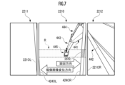
当該構成の遠隔操作装置20によれば、オペレータによる遠隔操作機構211の旋回操作に応じて、作業機械40の上部旋回体420が下部走行体410に対して右旋回した場合、図7に示されているように、撮像画像により示されているキャブ424の前方の様子が全体的に当該旋回方向(黒矢印参照)の反対方向(白矢印参照)に変位する。この場合、図7に示されているように、中央画像出力装置2210に表示される撮像画像において、左側ピラー4240Lの指定部分PPLの少なくとも一部が表示されないものの、右側ピラー4240Rの指定部分PPRの全部が表示される。これにより、中央画像出力装置2210に表示される撮像画像において、左側ピラー4240Lの面積よりも右側ピラー4240Rの面積が大きくなっている。図7では指定画像領域Rは、図5の実施形態にしたがって定義されているが、図6またはその他の実施形態にしたがって定義されていてもよい。
According to the
同様に、オペレータによる遠隔操作機構211の旋回操作に応じて、作業機械40の上部旋回体420が下部走行体410に対して左旋回した場合、図8に示されているように、撮像画像により示されているキャブ424の前方の様子が全体的に当該旋回方向(黒矢印参照)の反対方向(白矢印参照)に変位する。この場合、図8に示されているように、中央画像出力装置2210に表示される撮像画像において、左側ピラー4240Lの指定部分PPRの少なくとも一部が表示されないものの、右側ピラー4240Rの指定部分PPRの全部が表示される。これにより、中央画像出力装置2210に表示される撮像画像において、右側ピラー4240Rの面積よりも左側ピラー4240Lの面積が大きくなっている。図8では指定画像領域Rは、図6の実施形態にしたがって定義されているが、図5またはその他の実施形態にしたがって定義されていてもよい。
Similarly, when the upper
その結果、遠隔操作機構211の旋回操作に応じて、当該旋回方向に映り込むキャブ424の一方のピラー4240Lまたは4240Rと、当該ピラー4240Lまたは4240Rが表示される中央画像出力装置2210のベゼル2210Lまたは2210Rと、がオペレータにより誤認または混同される可能性の低減が図られる。上部旋回体420の右旋回時には、オペレータの視線の先または注意が中央画像出力装置2210の右側に寄り、上部旋回体420の左旋回時には、オペレータの視線の先または注意が中央画像出力装置2210の左側に寄る傾向があるため、当該表示態様の制御は特に有意義である。
As a result, in accordance with the turning operation of the
10‥遠隔操作支援サーバ、20‥遠隔操作装置、40‥作業機械、41‥実機入力インターフェース、42‥実機出力インターフェース、102‥データベース、121‥第1支援処理要素、122‥第2支援処理要素、200‥遠隔制御装置、210‥遠隔入力インターフェース、211‥遠隔操作機構、220‥遠隔出力インターフェース、221‥画像出力装置、400‥実機制御装置、410‥下部走行体、420‥上部旋回体、424‥キャブ(運転室)、440‥作業アタッチメント(作動機構)、445‥バケット(作業部)、2210‥中央画像出力装置(指定画像出力装置)、2211‥左側画像出力装置、2212‥右側画像出力装置、4240L‥左側ピラー、4240R‥右側ピラー、PPL、PPR‥ピラーの指定部分。 10...Remote operation support server, 20...Remote control device, 40...Work machine, 41...Actual machine input interface, 42...Actual machine output interface, 102...Database, 121...First support processing element, 122...Second support processing element, 200... Remote control device, 210... Remote input interface, 211... Remote operation mechanism, 220... Remote output interface, 221... Image output device, 400... Actual machine control device, 410... Lower traveling body, 420... Upper revolving body, 424... Cab (driver's cabin), 440...Work attachment (operation mechanism), 445...Bucket (work part), 2210...Central image output device (designated image output device), 2211...Left side image output device, 2212...Right side image output device, 4240L...Left side pillar, 4240R...Right side pillar, PPL, PPR...Specified part of pillar.
Claims (12)
前記遠隔操作機構の周囲に配置された一または複数の画像出力装置と、
遠隔制御装置と、を備え、
前記遠隔制御装置が、前記作業機械の運転室の内部に搭載されている実機撮像装置により取得された、前記運転室の前方の様子を示す撮像画像を前記一または複数の画像出力装置のうち指定画像出力装置に表示させ、かつ、前記指定画像出力装置において左右のベゼルの間で帯状に延在する指定画像領域に重なる、前記運転室を構成する一対のピラーのうち少なくとも一方のピラーの一部である指定部分の全部が表示されるように、前記指定画像出力装置における前記撮像画像の表示態様を可変に制御することを特徴とする遠隔操作装置。 a remote control mechanism operated by an operator to remotely control the work machine;
one or more image output devices arranged around the remote control mechanism;
comprising a remote control device;
The remote control device specifies, from among the one or more image output devices, a captured image showing a state in front of the operator's cab, which is acquired by an actual imaging device installed inside the operator's cab of the working machine. A portion of at least one of the pair of pillars constituting the driver's cab, which is displayed on an image output device and overlaps a designated image area extending in a band shape between left and right bezels in the designated image output device. A remote control device characterized in that a display mode of the captured image on the designated image output device is variably controlled so that the entire designated portion is displayed.
前記遠隔操作機構の前方に配置されている前記指定画像出力装置としての中央画像出力装置と、前記中央画像出力装置の左右側縁のそれぞれに隣接して、前記遠隔操作機構の左斜め前方および右斜め前方のそれぞれに配置されている左側画像出力装置および右側画像出力装置と、を前記複数の画像出力装置として備え、
前記遠隔制御装置が、前記右側画像出力装置、前記中央画像出力装置および前記左側画像出力装置に前記撮像画像を分割して表示させ、かつ、前記右側画像出力装置、前記中央画像出力装置および前記左側画像出力装置における前記撮像画像の分割表示態様を可変に制御することを特徴とする遠隔操作装置。 The remote control device according to claim 1,
A central image output device as the specified image output device disposed in front of the remote control mechanism, and adjacent to each of the left and right side edges of the central image output device, diagonally in front of the left and right sides of the remote control mechanism. The plurality of image output devices include a left side image output device and a right side image output device, each of which is disposed diagonally forward,
The remote control device causes the right side image output device, the central image output device, and the left side image output device to divide and display the captured image, and displays the captured image in the right side image output device, the center image output device, and the left side image output device. A remote control device that variably controls a divided display mode of the captured image on an image output device.
前記遠隔制御装置が、前記指定画像出力装置において前記作業機械を構成する作動機構の作業部が含まれている、帯状に延在する画像領域を前記指定画像領域として、前記少なくとも一方のピラーの前記指定部分の全部が表示されるように、前記指定画像出力装置における前記撮像画像の表示態様を可変に制御することを特徴とする遠隔操作装置。 The remote control device according to claim 1 or 2,
The remote control device determines, in the specified image output device, an image area extending in a belt shape and including a working part of an operating mechanism constituting the working machine as the specified image area. A remote control device that variably controls a display mode of the captured image on the designated image output device so that the entire designated portion is displayed.
前記遠隔制御装置が、前記指定画像出力装置において前記作業部の第1指定期間にわたる位置軌道の一部または全部が含まれている、帯状に延在する画像領域を前記指定画像領域として、前記少なくとも一方のピラーの前記指定部分の全部が表示されるように、前記指定画像出力装置における前記撮像画像の表示態様を可変に制御することを特徴とする遠隔操作装置。 The remote control device according to claim 3,
The remote control device sets an image area extending in a band shape that includes part or all of the position trajectory of the working unit over the first specified period in the specified image output device as the specified image area; A remote control device characterized in that a display mode of the captured image on the specified image output device is variably controlled so that the entire specified portion of one pillar is displayed.
前記遠隔制御装置が、前記指定画像出力装置において前記作業部の前記第1指定期間にわたる変位方向に対して平行な方向に帯状に延在する画像領域を前記指定画像領域として、前記少なくとも一方のピラーの前記指定部分の全部が表示されるように、前記指定画像出力装置における前記撮像画像の表示態様を可変に制御することを特徴とする遠隔操作装置。 The remote control device according to claim 4,
The remote control device may set an image area extending in a belt shape in a direction parallel to the displacement direction of the working unit over the first specified period in the specified image output device as the specified image area, and A remote control device characterized in that a display mode of the captured image on the specified image output device is variably controlled so that the entire specified portion of the image is displayed.
前記オペレータの視線を検知する視線検知装置をさらに備え、
前記遠隔制御装置が、前記指定画像出力装置において前記視線検知装置により検知された前記オペレータの第2指定期間にわたる視線の先の軌道の一部または全部が含まれている、帯状に延在する画像領域を前記指定画像領域として、前記少なくとも一方のピラーの前記指定部分の全部が表示されるように、前記指定画像出力装置における前記撮像画像の表示態様を可変に制御することを特徴とする遠隔操作装置。 The remote control device according to any one of claims 1 to 5,
Further comprising a line of sight detection device that detects the line of sight of the operator,
The remote control device generates an image extending in a band shape that includes part or all of the trajectory beyond the line of sight of the operator over a second specified period, which is detected by the line of sight detection device in the specified image output device. The remote control is characterized in that the display mode of the captured image on the designated image output device is variably controlled so that the entire designated portion of the at least one pillar is displayed with the designated image region as the designated image region. Device.
前記遠隔制御装置が、前記指定画像出力装置において前記視線検知装置により検知された前記オペレータの前記第2指定期間にわたる視線の先の変位方向に対して平行な方向に帯状に延在する画像領域を前記指定画像領域として、前記少なくとも一方のピラーの前記指定部分の全部が表示されるように、前記指定画像出力装置における前記撮像画像の表示態様を可変に制御することを特徴とする遠隔操作装置。 The remote control device according to claim 6,
The remote control device defines an image area extending in a belt shape in a direction parallel to a direction of displacement of the operator's line of sight detected by the line of sight detection device in the designated image output device over the second specified period. A remote control device characterized in that a display mode of the captured image on the specified image output device is variably controlled so that the entire specified portion of the at least one pillar is displayed as the specified image area.
前記遠隔制御装置が、前記遠隔操作機構における前記オペレータによる操作態様の相違に応じて、前記指定画像出力装置における前記撮像画像の表示態様を可変に制御することを特徴とする遠隔操作装置。 The remote control device according to any one of claims 1 to 7,
The remote control device is characterized in that the remote control device variably controls the display mode of the captured image on the designated image output device according to the difference in the operation mode of the operator on the remote control mechanism.
前記遠隔制御装置が、前記遠隔操作機構において前記運転室が搭載されている上部旋回体を下部走行体に対して旋回させるための旋回操作があった場合、左右一対のピラーのうち、前記上部旋回体の旋回方向にある一方のピラーが他方のピラーよりも偏重的に前記指定画像出力装置に表示されるように、前記指定画像出力装置における前記撮像画像の表示態様を可変に制御することを特徴とする遠隔操作装置。 The remote control device according to claim 8,
When the remote control device performs a turning operation in the remote control mechanism to turn the upper rotating body on which the driver's cab is mounted relative to the lower traveling body, the upper rotating body of the pair of left and right pillars A display mode of the captured image on the specified image output device is variably controlled so that one pillar in the direction of rotation of the body is displayed on the specified image output device with more emphasis than the other pillar. remote control device.
前記作業機械を構成する運転室の内部に搭載されている実機撮像装置により取得された前記運転室の前方の様子を示す撮像画像を、前記作業機械との通信に基づいて取得する第1支援処理要素と、
前記遠隔操作装置との通信に基づき、前記遠隔操作装置を構成する一または複数の画像出力装置のうち指定画像出力装置において左右のベゼルの間で帯状に延在する指定画像領域に重なる、前記運転室を構成する一対のピラーのうち少なくとも一方のピラーの一部である指定部分の全部が表示されるように、前記指定画像出力装置における前記撮像画像の表示態様を可変に制御する第2支援処理要素と、を備えていることを特徴とする遠隔操作支援サーバ。 A remote operation support server for supporting remote operation of a work machine through a remote control device,
a first support process of acquiring, based on communication with the working machine, a captured image showing the state in front of the operator's cab, which is acquired by an actual imaging device installed inside the operator's cab constituting the working machine; element and
Based on the communication with the remote control device, the operation mode overlaps with a designated image area extending in a band shape between the left and right bezels of the designated image output device among one or more image output devices constituting the remote control device. a second support process for variably controlling the display mode of the captured image in the designated image output device so that the entire designated portion that is a part of at least one of a pair of pillars constituting the room is displayed; A remote operation support server comprising the following elements.
前記作業機械を構成する運転室の内部に搭載されている実機撮像装置により取得された前記運転室の前方の様子を示す撮像画像を、前記作業機械との通信に基づいて取得する第1支援処理と、
前記遠隔操作装置との通信に基づき、前記遠隔操作装置を構成する一または複数の画像出力装置のうち指定画像出力装置において左右のベゼルの間で帯状に延在する指定画像領域に重なる、前記運転室を構成する一対のピラーのうち少なくとも一方のピラーの一部である指定部分の全部が表示されるように、前記指定画像出力装置における前記撮像画像の表示態様を可変に制御する第2支援処理と、を含んでいることを特徴とする遠隔操作支援方法。 A method for supporting remote control of a work machine through a remote control device, the method comprising:
a first support process of acquiring, based on communication with the working machine, a captured image showing the state in front of the operator's cab, which is acquired by an actual imaging device installed inside the operator's cab constituting the working machine; and,
Based on the communication with the remote control device, the operation mode overlaps with a designated image area extending in a band shape between the left and right bezels of the designated image output device among one or more image output devices constituting the remote control device. a second support process for variably controlling the display mode of the captured image in the designated image output device so that the entire designated portion that is a part of at least one of a pair of pillars constituting the room is displayed; A remote operation support method comprising:
Priority Applications (5)
| Application Number | Priority Date | Filing Date | Title |
|---|---|---|---|
| JP2020025720A JP7363560B2 (en) | 2020-02-18 | 2020-02-18 | Remote control device, remote control support server, remote control support system, and remote control support method |
| US17/794,089 US20230056724A1 (en) | 2020-02-18 | 2021-01-07 | Remote operation device, remote operation assistance server, remote operation assistance system, and remote operation assistance method |
| EP21757735.2A EP4075795A4 (en) | 2020-02-18 | 2021-01-07 | Remote operation device, remote operation assistance server, remote operation assistance system, and remote operation assistance method |
| CN202180014247.7A CN115088251A (en) | 2020-02-18 | 2021-01-07 | Remote operation device, remote operation support server, remote operation support system, and remote operation support method |
| PCT/JP2021/000337 WO2021166475A1 (en) | 2020-02-18 | 2021-01-07 | Remote operation device, remote operation assistance server, remote operation assistance system, and remote operation assistance method |
Applications Claiming Priority (1)
| Application Number | Priority Date | Filing Date | Title |
|---|---|---|---|
| JP2020025720A JP7363560B2 (en) | 2020-02-18 | 2020-02-18 | Remote control device, remote control support server, remote control support system, and remote control support method |
Publications (2)
| Publication Number | Publication Date |
|---|---|
| JP2021130932A JP2021130932A (en) | 2021-09-09 |
| JP7363560B2 true JP7363560B2 (en) | 2023-10-18 |
Family
ID=77390735
Family Applications (1)
| Application Number | Title | Priority Date | Filing Date |
|---|---|---|---|
| JP2020025720A Active JP7363560B2 (en) | 2020-02-18 | 2020-02-18 | Remote control device, remote control support server, remote control support system, and remote control support method |
Country Status (5)
| Country | Link |
|---|---|
| US (1) | US20230056724A1 (en) |
| EP (1) | EP4075795A4 (en) |
| JP (1) | JP7363560B2 (en) |
| CN (1) | CN115088251A (en) |
| WO (1) | WO2021166475A1 (en) |
Citations (5)
| Publication number | Priority date | Publication date | Assignee | Title |
|---|---|---|---|---|
| WO2016013691A1 (en) | 2015-10-15 | 2016-01-28 | 株式会社小松製作所 | Position measuring system and position measuring method |
| JP2018207244A (en) | 2017-05-31 | 2018-12-27 | 株式会社小松製作所 | Display system, display method, and remote control system |
| WO2019003431A1 (en) | 2017-06-30 | 2019-01-03 | 株式会社小松製作所 | Imaging device, construction machine, and imaging system |
| JP2019007139A (en) | 2017-06-20 | 2019-01-17 | コベルコ建機株式会社 | Remote control system for construction machinery |
| JP2019167733A (en) | 2018-03-23 | 2019-10-03 | コベルコ建機株式会社 | Construction machine |
Family Cites Families (1)
| Publication number | Priority date | Publication date | Assignee | Title |
|---|---|---|---|---|
| JP6891087B2 (en) * | 2017-09-29 | 2021-06-18 | 株式会社小松製作所 | Work vehicle, display device, and fault determination method |
-
2020
- 2020-02-18 JP JP2020025720A patent/JP7363560B2/en active Active
-
2021
- 2021-01-07 US US17/794,089 patent/US20230056724A1/en active Pending
- 2021-01-07 EP EP21757735.2A patent/EP4075795A4/en active Pending
- 2021-01-07 CN CN202180014247.7A patent/CN115088251A/en active Pending
- 2021-01-07 WO PCT/JP2021/000337 patent/WO2021166475A1/en unknown
Patent Citations (5)
| Publication number | Priority date | Publication date | Assignee | Title |
|---|---|---|---|---|
| WO2016013691A1 (en) | 2015-10-15 | 2016-01-28 | 株式会社小松製作所 | Position measuring system and position measuring method |
| JP2018207244A (en) | 2017-05-31 | 2018-12-27 | 株式会社小松製作所 | Display system, display method, and remote control system |
| JP2019007139A (en) | 2017-06-20 | 2019-01-17 | コベルコ建機株式会社 | Remote control system for construction machinery |
| WO2019003431A1 (en) | 2017-06-30 | 2019-01-03 | 株式会社小松製作所 | Imaging device, construction machine, and imaging system |
| JP2019167733A (en) | 2018-03-23 | 2019-10-03 | コベルコ建機株式会社 | Construction machine |
Also Published As
| Publication number | Publication date |
|---|---|
| US20230056724A1 (en) | 2023-02-23 |
| EP4075795A1 (en) | 2022-10-19 |
| EP4075795A4 (en) | 2023-06-14 |
| CN115088251A (en) | 2022-09-20 |
| JP2021130932A (en) | 2021-09-09 |
| WO2021166475A1 (en) | 2021-08-26 |
Similar Documents
| Publication | Publication Date | Title |
|---|---|---|
| JP7151392B2 (en) | Remote control device for construction machinery | |
| WO2019003431A1 (en) | Imaging device, construction machine, and imaging system | |
| JP7287262B2 (en) | Remote control system and remote control server | |
| JP7318258B2 (en) | Remote control system and remote control server | |
| WO2021176883A1 (en) | Work support server and work support method | |
| JP7363560B2 (en) | Remote control device, remote control support server, remote control support system, and remote control support method | |
| JP7452038B2 (en) | Work support system | |
| JP7392422B2 (en) | Work support server and work support system | |
| JP2023040971A (en) | Remote control support device, remote control support system, and remote control support method | |
| JP7376440B2 (en) | Remote control device and remote control system | |
| JP7409074B2 (en) | How to select work support server and imaging device | |
| WO2023136070A1 (en) | Remote operation support system and remote operation support method | |
| JP7367606B2 (en) | Remote operation support device and remote operation support method | |
| JP7444094B2 (en) | Remote operation support system and remote operation support method | |
| WO2023100533A1 (en) | Image display system, remote operation assistance system, and image display method | |
| WO2023026568A1 (en) | Remote operation system and remote operation composite system | |
| WO2021106280A1 (en) | Work assist server, work assist method, and work assist system | |
| JP2023032997A (en) | remote control system | |
| WO2021240957A1 (en) | Remote operation assisting device, remote operation assisting system, and remote operation assisting method | |
| JP7415480B2 (en) | Work support server and work support system | |
| WO2022230939A1 (en) | Display control device, display control method, and work machine | |
| JP2022144491A (en) | Imaging function control system and imaging function control method | |
| JP2024057361A (en) | Work support device and work support method | |
| JP2024057362A (en) | Work support system, remote operation support system, work support method and display device | |
| CN117043732A (en) | Remote operation support server and remote operation support system |
Legal Events
| Date | Code | Title | Description |
|---|---|---|---|
| A621 | Written request for application examination |
Free format text: JAPANESE INTERMEDIATE CODE: A621 Effective date: 20221012 |
|
| TRDD | Decision of grant or rejection written | ||
| A01 | Written decision to grant a patent or to grant a registration (utility model) |
Free format text: JAPANESE INTERMEDIATE CODE: A01 Effective date: 20230905 |
|
| A61 | First payment of annual fees (during grant procedure) |
Free format text: JAPANESE INTERMEDIATE CODE: A61 Effective date: 20230918 |
|
| R150 | Certificate of patent or registration of utility model |
Ref document number: 7363560 Country of ref document: JP Free format text: JAPANESE INTERMEDIATE CODE: R150 |