WO2022038892A1 - 車載レーダー装置用レドーム及び車載レーダー構造 - Google Patents
車載レーダー装置用レドーム及び車載レーダー構造 Download PDFInfo
- Publication number
- WO2022038892A1 WO2022038892A1 PCT/JP2021/023881 JP2021023881W WO2022038892A1 WO 2022038892 A1 WO2022038892 A1 WO 2022038892A1 JP 2021023881 W JP2021023881 W JP 2021023881W WO 2022038892 A1 WO2022038892 A1 WO 2022038892A1
- Authority
- WO
- WIPO (PCT)
- Prior art keywords
- electromagnetic wave
- heater wire
- base material
- radar device
- irradiation region
- Prior art date
- Legal status (The legal status is an assumption and is not a legal conclusion. Google has not performed a legal analysis and makes no representation as to the accuracy of the status listed.)
- Ceased
Links
Images

Classifications
-
- H—ELECTRICITY
- H01—ELECTRIC ELEMENTS
- H01Q—ANTENNAS, i.e. RADIO AERIALS
- H01Q1/00—Details of, or arrangements associated with, antennas
- H01Q1/27—Adaptation for use in or on movable bodies
- H01Q1/32—Adaptation for use in or on road or rail vehicles
-
- G—PHYSICS
- G01—MEASURING; TESTING
- G01S—RADIO DIRECTION-FINDING; RADIO NAVIGATION; DETERMINING DISTANCE OR VELOCITY BY USE OF RADIO WAVES; LOCATING OR PRESENCE-DETECTING BY USE OF THE REFLECTION OR RERADIATION OF RADIO WAVES; ANALOGOUS ARRANGEMENTS USING OTHER WAVES
- G01S7/00—Details of systems according to groups G01S13/00, G01S15/00, G01S17/00
- G01S7/02—Details of systems according to groups G01S13/00, G01S15/00, G01S17/00 of systems according to group G01S13/00
- G01S7/03—Details of HF subsystems specially adapted therefor, e.g. common to transmitter and receiver
-
- G—PHYSICS
- G01—MEASURING; TESTING
- G01S—RADIO DIRECTION-FINDING; RADIO NAVIGATION; DETERMINING DISTANCE OR VELOCITY BY USE OF RADIO WAVES; LOCATING OR PRESENCE-DETECTING BY USE OF THE REFLECTION OR RERADIATION OF RADIO WAVES; ANALOGOUS ARRANGEMENTS USING OTHER WAVES
- G01S7/00—Details of systems according to groups G01S13/00, G01S15/00, G01S17/00
- G01S7/02—Details of systems according to groups G01S13/00, G01S15/00, G01S17/00 of systems according to group G01S13/00
- G01S7/40—Means for monitoring or calibrating
-
- H—ELECTRICITY
- H01—ELECTRIC ELEMENTS
- H01Q—ANTENNAS, i.e. RADIO AERIALS
- H01Q1/00—Details of, or arrangements associated with, antennas
- H01Q1/02—Arrangements for de-icing; Arrangements for drying-out ; Arrangements for cooling; Arrangements for preventing corrosion
-
- H—ELECTRICITY
- H01—ELECTRIC ELEMENTS
- H01Q—ANTENNAS, i.e. RADIO AERIALS
- H01Q1/00—Details of, or arrangements associated with, antennas
- H01Q1/42—Housings not intimately mechanically associated with radiating elements, e.g. radome
-
- H—ELECTRICITY
- H01—ELECTRIC ELEMENTS
- H01Q—ANTENNAS, i.e. RADIO AERIALS
- H01Q1/00—Details of, or arrangements associated with, antennas
- H01Q1/42—Housings not intimately mechanically associated with radiating elements, e.g. radome
- H01Q1/425—Housings not intimately mechanically associated with radiating elements, e.g. radome comprising a metallic grid
-
- B—PERFORMING OPERATIONS; TRANSPORTING
- B60—VEHICLES IN GENERAL
- B60R—VEHICLES, VEHICLE FITTINGS, OR VEHICLE PARTS, NOT OTHERWISE PROVIDED FOR
- B60R13/00—Elements for body-finishing, identifying, or decorating; Arrangements or adaptations for advertising purposes
Definitions
- the present invention relates to a radome for an in-vehicle radar device provided on the front side of the in-vehicle radar device, and particularly relates to a radome for an in-vehicle radar device having a snowmelt function and an in-vehicle radar structure including the radome.
- radomes of Patent Documents 1 and 2 that can suppress attenuation when a millimeter wave is transmitted while exhibiting a snowmelt function.
- This radome has a decorative main body having millimeter wave transparency and a linear heater wire, and the heater wire has a plurality of straight portions extending in parallel with each other, and the ends of adjacent straight portions are arcuate. It is composed of connected parts at the folded part of.
- a plurality of linear portions thereof are arranged in the millimeter wave irradiation region, and all the linear portions in the millimeter wave irradiation region are arranged so that the allowable value of the millimeter wave attenuation is 2.5 dB or less.
- the area ratio to the millimeter wave irradiation area is set to be 10% or less.
- Patent Documents 1 and 2 when the straight portion of the heater wire is made parallel to the polarization plane of the millimeter wave, the millimeter wave may come into surface contact with the straight portion of the heater wire, and the transmission is hindered.
- the area where the millimeter wave contacts the straight part of the heater wire is minimized and transmission is hindered. It is disclosed that the amount of millimeter waves can be minimized to minimize the amount of millimeter wave attenuation.
- the radomes of Patent Documents 1 and 2 it is possible to suppress the attenuation of millimeter waves by setting the area ratio of the straight portion of the heater wire to the millimeter wave irradiation region to 10% or less.
- the area ratio of the straight part of the heater wire to the millimeter wave irradiation area is 10%. If the area ratio is set to any of the following, the practical snow melting function may not be exhibited.
- the present invention has been proposed in view of the above problems, and is capable of exhibiting a practical snow melting function as a radome for an in-vehicle radar device while suppressing the attenuation of electromagnetic waves emitted by the in-vehicle radar device within an allowable range. It is an object of the present invention to provide a radome for a radar device and an in-vehicle radar structure.
- the redo for an in-vehicle radar device of the present invention has a base material that is transparent to electromagnetic waves and a base material having a heater wire that is laminated and arranged on the inner surface side of the base material and wired in the surface direction of the base material.
- the straight portions of the heater wire are arranged side by side at intervals in the surface direction of the base material, and the surface occupancy rate of the straight portion of the heater wire in the electromagnetic wave irradiation region of the base material is 1% or more. It is characterized by being set to 24% or less.
- the temperature of the outer surface of the base material can be set to a state of more than 0 ° C. Therefore, it is possible to exhibit a practical snow melting function as a radome for an in-vehicle radar device while suppressing the attenuation of electromagnetic waves emitted by the in-vehicle radar device within a required allowable range.
- the linear portion of the heater wire is juxtaposed so as to extend substantially perpendicular to the plane of polarization of the linearly polarized electromagnetic wave irradiated by the in-vehicle radar device.
- the surface occupancy of the straight portion of the heater wire in the electromagnetic wave irradiation region is set to 1% or more and 24% or less. According to this, it is possible to exhibit a practical snow melting function as a radome for an in-vehicle radar device, and it is possible to secure the transmittance of the substrate to the electromagnetic wave irradiated by the in-vehicle radar device to -1.5 dB or more, and the electromagnetic wave. Attenuation can be suppressed within a practically high enough level of tolerance.
- the linear portion of the heater wire is juxtaposed so as to extend substantially perpendicular to the plane of polarization of the linearly polarized electromagnetic wave irradiated by the in-vehicle radar device.
- the surface occupancy of the straight portion of the heater wire in the electromagnetic wave irradiation region is set to 3% or more and 20% or less. According to this, even when the environment temperature is -15 ° C and the vehicle travels at a speed of 100 km / h, the temperature of the outer surface of the base material can be kept above 0 ° C, even in a harsher cold environment. It is possible to surely melt the snow of the radome for the in-vehicle radar device.
- the transmittance of the substrate for the electromagnetic waves emitted by the in-vehicle radar device can be ensured to be ⁇ 1.0 dB or more, and the attenuation of the electromagnetic waves can be suppressed within a very high level tolerance that is practically sufficient.
- the straight portion of the heater wire is arranged side by side so as to extend substantially perpendicular to the polarization plane of the electromagnetic wave of linear polarization irradiated by the in-vehicle radar device, and the straight portion of the heater wire in the electromagnetic wave irradiation region of the base material.
- redome having a configuration in which the surface occupancy rate is set to 1% or more and 20% or less, and the straight portion of the heater wire is substantially relative to the polarization plane of the linearly polarized electromagnetic wave irradiated by the in-vehicle radar device. It is also good as a radar having a structure in which the surface occupancy of the straight portion of the heater wire in the electromagnetic wave irradiation region of the base material is set to 3% or more and 24% or less in parallel so as to extend vertically.
- the linear portion of the heater wire is juxtaposed so as to extend substantially perpendicular to the plane of polarization of the linearly polarized electromagnetic wave irradiated by the in-vehicle radar device.
- the surface occupancy of the straight portion of the heater wire in the electromagnetic wave irradiation region is set to 3% or more and 7.5% or less. According to this, even when the environment temperature is -15 ° C and the vehicle travels at a speed of 100 km / h, the temperature of the outer surface of the base material can be kept above 0 ° C, even in a harsher cold environment. It is possible to surely melt the snow of the radome for the in-vehicle radar device.
- the transmittance of the substrate against the electromagnetic waves emitted by the in-vehicle radar device can be ensured to be ⁇ 0.35 dB or more, and a very high electromagnetic wave transmittance can be ensured.
- the linear portion of the heater wire is juxtaposed so as to extend substantially parallel to the polarization plane of the linearly polarized electromagnetic wave irradiated by the in-vehicle radar device.
- the surface occupancy of the straight portion of the heater wire in the electromagnetic wave irradiation region is set to 1% or more and 16% or less. According to this, it is possible to exhibit a practical snow melting function as a radome for an in-vehicle radar device, and it is possible to secure the transmittance of the substrate to the electromagnetic wave irradiated by the in-vehicle radar device to -1.5 dB or more, and the electromagnetic wave. Attenuation can be suppressed within a practically high enough level of tolerance.
- the linear portion of the heater wire is juxtaposed so as to extend substantially parallel to the polarization plane of the linearly polarized electromagnetic wave irradiated by the in-vehicle radar device.
- the surface occupancy of the straight portion of the heater wire in the electromagnetic wave irradiation region is set to 3% or more and 13% or less. According to this, even when the environment temperature is -15 ° C and the vehicle travels at a speed of 100 km / h, the temperature of the outer surface of the base material can be kept above 0 ° C, even in a harsher cold environment. It is possible to surely melt the snow of the radome for the in-vehicle radar device.
- the transmittance of the substrate for the electromagnetic waves emitted by the in-vehicle radar device can be ensured to be ⁇ 1.0 dB or more, and the attenuation of the electromagnetic waves can be suppressed within a very high level tolerance that is practically sufficient.
- the straight portion of the heater wire is arranged side by side so as to extend substantially parallel to the polarization plane of the electromagnetic wave of linear polarization irradiated by the in-vehicle radar device, and the straight portion of the heater wire in the electromagnetic wave irradiation region of the base material.
- redome having a configuration in which the surface occupancy rate is set to 1% or more and 13% or less, and the straight portion of the heater wire is substantially relative to the polarization plane of the linearly polarized electromagnetic wave irradiated by the in-vehicle radar device. It is also good as a radar having a structure in which the surface occupancy of the straight portion of the heater wire in the electromagnetic wave irradiation region of the base material is set to 3% or more and 16% or less so as to extend in parallel.
- the heater wires are wired so as to fold back and meander, the directions of currents flowing in the straight portions of the adjacent heater wires are substantially antiparallel to each other, and the electromagnetic waves of the substrate are used. It is characterized in that at least four linear portions of the heater wires are arranged side by side in the irradiation region at an approximate pitch. According to this, the direction of the current flowing in the straight part of the adjacent heater wires is made antiparallel to each other, the electromagnetic waves radiated from the adjacent heater wires are set to the opposite phase, and the electromagnetic radiation from the heater wires can be canceled. Excellent electromagnetic wave transmission performance can be obtained.
- the temperature distribution in the entire electromagnetic wave irradiation region of the base material can be further leveled, and the temperature can be increased when the heater wire is heated. It is possible to prevent the generation of a low local region, and it is possible to more reliably melt the snow over the entire electromagnetic wave irradiation region of the base material.
- the heater wires are wired so as to fold back and meander, and the directions of the currents flowing in the straight portions of the adjacent heater wires are substantially antiparallel to each other and within the electromagnetic wave irradiation region.
- the straight portion of the heater wire outside the electromagnetic wave irradiation region adjacent to the linear portion of the heater wire is provided at a pitch close to the pitch of the linear portions of the heater wire in the electromagnetic wave irradiation region, and the electromagnetic wave irradiation is performed.
- the straight portion of the heater wire outside the region is extended with a length equal to or longer than the length of the straight portion of the heater wire in the adjacent electromagnetic wave irradiation region in the electromagnetic wave irradiation region. According to this, the direction of the current flowing in the straight part of the adjacent heater wires is made antiparallel to each other, the electromagnetic waves radiated from the adjacent heater wires are set to the opposite phase, and the electromagnetic radiation from the heater wires can be canceled. Excellent electromagnetic wave transmission performance can be obtained.
- the straight portion of the heater wire outside the electromagnetic wave irradiation region adjacent to the straight portion of the heater wire in the electromagnetic wave irradiation region is provided at a pitch close to the mutual pitch of the straight portions of the heater wire in the electromagnetic wave irradiation region.
- the vehicle-mounted radar structure of the present invention is characterized by comprising the radome for the vehicle-mounted radar device of the present invention and the vehicle-mounted radar device that irradiates the radome for the vehicle-mounted radar device with a linearly polarized electromagnetic wave. According to this, it is possible to obtain an in-vehicle radar structure that exhibits the effect of the radome for an in-vehicle radar device of the present invention.
- the present invention it is possible to exhibit a practical snow melting function as a radome for an in-vehicle radar device while suppressing the attenuation of electromagnetic waves emitted by the in-vehicle radar device within an allowable range.
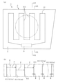
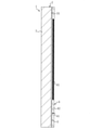
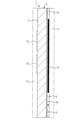
- FIG. 1 is an enlarged cross-sectional view taken along the line AA of FIG. BB enlarged sectional view of FIG.
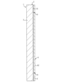
- FIG. 5 is a cross-sectional explanatory view illustrating a modified example of the radome for an in-vehicle radar device according to the embodiment.
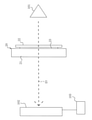
- the schematic diagram of the measuring device of the experimental example which measured the relationship between the surface occupancy rate of a heater wire and the electromagnetic wave transmittance in an electromagnetic wave irradiation area.
- (A) is a schematic diagram illustrating a state in which the sample is irradiated with electromagnetic waves with the polarization plane of linear polarization perpendicular to the straight line portion of the heater wire of the sample used in the experimental example, and (b) is used in the experimental example.
- Example graph The graph of the experimental example which shows the relationship between the surface occupancy rate of a heater wire and the outer surface temperature of a sample in the case of an environmental temperature of -5 ° C and the case of an environmental temperature of -15 ° C.
- the radome 1 for an in-vehicle radar device according to the present invention is laminated with the electromagnetic wave transmitting base material 3 on the inner surface side of the base material 3, in other words, on the center side of the vehicle. It is composed of a substrate 2 provided with a heater wire 41 which is wired in the plane direction of the substrate 3.
- the base material 3 an appropriate material such as synthetic resin, glass, and ceramics can be used within the scope of the present invention, but it is preferable to use an insulating synthetic resin.
- the radome 1 in the illustrated example is a bumper cover attached to the bumper of a vehicle, and the base material 3 is made of an insulating synthetic resin.
- the base material 3 is an insulating synthetic resin
- the material is appropriate to the extent applicable, and for example, acrylonitrile-butadiene-styrene copolymer (ABS), polypropylene (PP), polymethylmethacrylate (PMMA), etc.
- Acrylic resin polycarbonate (PC), polyethylene terephthalate (PET), polyethylene (PE), acrylonitrile-styrene copolymer (AS), polystyrene (PS), cycloolefin polymer (COP), acrylonitrile-styrene-acrylate copolymer (ASA), acrylonitrile-ethylenepropyl rubber-styrene copolymer (AES) and the like can be used alone or in combination of two or more, or may contain an additive.
- PC polycarbonate
- PET polyethylene terephthalate
- PE polyethylene
- AS acrylonitrile-styrene copolymer
- PS polystyrene
- COP cycloolefin polymer
- ASA acrylonitrile-styrene-acrylate copolymer
- AES acrylonitrile-ethylenepropyl rubber-styrene copolymer
- the heater wire 41 in the present embodiment constitutes a part of the heater sheet 4, and the heater sheet 4 is composed of the heater wire 41 and the electromagnetic wave transmitting insulating film 42.
- the heater wire 41 of the illustrated example is provided so as to be entirely embedded in the planar insulating film 42 or embedded so as to be exposed on the back surface side of the planar insulating film 42.
- the heater wire 41 can be made of an appropriate conductive material such as nichrome wire, iron chromium, copper, silver, carbon fiber, a transparent conductive film such as an ITO film, and the like.
- the insulating film 42 can be an insulating material having appropriate electromagnetic transmission applicable, for example, polycarbonate (PC), polyethylene (PE), polypropylene (PP, OPP), polyethylene terephthalate (PET). ), Polyethylene naphthalate (PEN), vinyl chloride (PVC), polystyrene (PS), acrylic (AC), or an insulating synthetic resin such as polyetheretherketone (PEEK).
- PC polycarbonate
- PE polyethylene
- PP polypropylene
- PET polyethylene terephthalate
- PEN Polyethylene naphthalate
- PVC vinyl chloride
- PS polystyrene
- AC acrylic
- PEEK polyetheretherketone
- the heater sheet 4 can have an appropriate configuration within an applicable range, for example, the insulating film 42. It is also suitable that the heater wire 41 is fixed to the back side or the inner surface side located on the center side of the vehicle, and further, the heater wire 41 is attached to the back side or the inner surface side located on the center side of the vehicle of the insulating film 42. It is also suitable as a configuration in which the protective film is laminated and fixed on the insulating film 42 so as to cover the heater wire 41 from the back surface side.
- Both ends of the heater wire 41 are electrically connected to and mechanically fixed to the connector 6 at the bottom of the in-vehicle radar device radome 1 of the illustrated example, and the connector 6 and the electric cable (not shown) connected to the connector 6 are mechanically fixed. Electric power is supplied to the heater wire 41 via the above, and the heater wire 41 generates heat.
- the heater wire 41 is formed by meandering in the direction in which the back surface 31 of the base material 3 expands or along the back surface 31 and being wired so as to be folded back and extending in a series, and is formed in the electromagnetic wave irradiation region R of the base material 3 and its outside.
- the straight portions 411 of the heater wires 41 are arranged side by side at intervals along the surface direction of the base material 3 or the back surface 31, and the directions of the currents flowing through the straight portions 411 of the adjacent heater wires 41 are substantially antiparallel to each other. Alternatively, it is set to be antiparallel.
- the electromagnetic waves radiated from the straight portions 411 and 411 of the adjacent heater wires 41 are opposite in phase. Therefore, it is possible to cancel the electromagnetic radiation from the straight portion 411 of the heater wire 41 and obtain better electromagnetic wave transmission performance.
- at least four heaters are arranged side by side at a pitch P close to the linear portion 411 of the heater wire 41 in the electromagnetic wave irradiation region R of the base material 3, and in the illustrated example, the heater is installed in the electromagnetic wave irradiation region R of the base material 3.
- Four straight portions 411 of the line 41 are arranged side by side at an approximate pitch P.
- the linear portion 411n of the heater wire 41 outside the electromagnetic wave irradiation region R adjacent to the linear portion 411 m of the heater wire 41 in the electromagnetic wave irradiation region R of the base material 3 is the heater wire in the electromagnetic wave irradiation region R.
- the straight portion 411n of the heater wire 41 outside the electromagnetic wave irradiation region R is provided with a pitch P close to the mutual pitch P of the linear portions 411 and 411 of 41, and the straight portion 411n of the heater wire 41 in the adjacent electromagnetic wave irradiation region R is the straight portion of the heater wire 41.
- the pitch P between the straight portion 411m and the straight portion 411n of the heater wire 41 is provided at a pitch P close to the pitch P between the straight portions 411 and 411 of the heater wire 41 in the electromagnetic wave irradiation region R.
- the straight portion 411n of the line 41 extends substantially antiparallel with the straight portion 411m at a length substantially equal to that of the straight portion 411m, and is substantially antiparallel with a length exceeding the length in the electromagnetic wave irradiation region R of the straight portion 411m. 411n is extended outside the electromagnetic wave irradiation region R.
- the approximation of the approximate pitch P between the straight portions 411 and 411 of the heater wire 41 including the linear portions 411m and 411n is the minimum pitch Pmin, the maximum pitch Pmax, the minimum pitch Pmin and the maximum pitch Pmax.
- the intermediate value is the intermediate pitch Pmid, it means that the minimum pitch Pmin / intermediate pitch Pmid is 0.80 or more and the maximum pitch Pmax / intermediate pitch Pmid is 1.2 or less.
- the surface occupancy of the straight portion 411 of the heater wire 41 is set to be 1% or more and 24% or less in the electromagnetic wave irradiation region R of the base material 3.
- a line 41 is provided.
- the line width W of the straight portion 411 is 0.07 mm to 1.68 mm.
- the surface occupancy of the linear portion 411 of the heater wire 41 in the electromagnetic wave irradiation region R of the base material 3 is set to 1% or more and 20% or less, or in the electromagnetic wave irradiation region R of the base material 3.
- the surface occupancy of the straight portion 411 of the heater wire 41 is set to 3% or more and 24% or less, or the surface occupancy of the straight portion 411 of the heater wire 41 in the electromagnetic wave irradiation region R of the base material 3 is 3%. It is preferable that the configuration is set to 20% or less.
- the space between the straight portions 411 and 411 of the heater wire 41 is provided.
- the pitch P is 7.0 mm
- the line width W of the straight line portion 411 is 0.21 to 1.40 mm.
- the linear portion 411 of the heater wire 41 is juxtaposed so as to extend substantially parallel or parallel to the polarization plane of the linearly polarized electromagnetic wave irradiated by the in-vehicle radar device 10 described later.
- the line width W of the straight portion 411 is 0.07 to 1.12 mm.
- the surface occupancy of the linear portion 411 of the heater wire 41 in the electromagnetic wave irradiation region R of the base material 3 is set to 1% or more and 13% or less, or in the electromagnetic wave irradiation region R of the base material 3.
- the surface occupancy of the straight portion 411 of the heater wire 41 is set to 3% or more and 16% or less, or the surface occupancy of the straight portion 411 of the heater wire 41 in the electromagnetic wave irradiation region R of the base material 3 is 3%. It is preferable to set it to 13% or less.
- the straight portion 411 and 411 of the heater wire 41 are provided with each other.
- the pitch P is 7.0 mm
- the line width W of the straight line portion 411 is 0.21 to 0.91 mm.
- the insulating film 42 and the protective film have a base material 3 and a refractive index n defined based on the complex dielectric constant. It is preferable from the viewpoint of improving the transmission performance of electromagnetic waves to use those that match each other or have substantially the same or close refractive index n.
- the difference between the refractive indexes is 0. It is good to keep it within the range of ⁇ 10%.
- the refractive index n here is a quantity defined as a mathematical formula 1 from the relative permittivity real part ⁇ r'and the relative permittivity imaginary part ⁇ r'.
- a permittivity having a dielectric constant tan ⁇ of 0.1 or less which is defined as Equation 2 from the ratio of the imaginary part and the real part at the applied frequency. It is preferable that the size of the real part is 3 or less. Dielectric permittivity and non-dielectric constant By setting the size of the real part to these values or less, the refractive index and internal loss required for the redome are surely reduced. It becomes possible to.
- the heater sheet 4 in the present embodiment is fixed to the inner surface side or the back surface side of the base material 3 via the adhesive layer 5.
- the adhesive layer 5 is made of an appropriate electromagnetically permeable insulating material that can be applied, and is, for example, an adhesive such as methyl acrylate, ethyl acrylate, butyl acrylate, methyl methacrylate, ethyl methacrylate, or an acrylic type. It is possible to form a double-sided tape composed of a core material such as PET, polypropylene, acrylic foam, or a double-sided tape containing only an adhesive without a core material in an adhesive such as silicon.
- the structure in which the heater sheet 4 and the insulating film 42 are welded and fixed to the base material 3 is also good.
- the base material 3 and the insulating film 42, or the base material 3, the insulating film 42 and the protective film, and the refractive index n defined based on the complex permittivity are mutually matched, or the refractive index n. It is preferable to use materials that are substantially the same or close to each other from the viewpoint of improving the transmission performance of electromagnetic waves.
- the numerical range of the refractive index n close to the adhesive layer 5 and the base material 3, the refractive index n close to the adhesive layer 5 and the insulating film 42, and the refractive index n close to the adhesive layer 5 and the protective film is of each refractive index. It is good to keep the difference in the range of 0 to 10%.
- these refractive indexes n are also quantities defined as Equation 1 from the relative permittivity real part ⁇ r'and the relative permittivity imaginary part ⁇ r ".
- the applied frequency of the material of the adhesive layer 5 from the viewpoint of permeability. It is preferable to use a permittivity tan ⁇ having a size of 0.1 or less, which is defined as Equation 2 from the ratio of the imaginary part and the real part in. The size of the real part of the relative permittivity is 3. The following is preferable.
- the radome 1 for the in-vehicle radar device is arranged in front of the in-vehicle radar device 10 arranged on the center side of the vehicle and attached to the vehicle to form an in-vehicle radar structure.
- the vehicle-mounted radar device 10 irradiates the radome 1 for the vehicle-mounted radar device with a linearly polarized electromagnetic wave.
- the wavelength or frequency of the electromagnetic wave emitted by the in-vehicle radar device 10 is appropriate as necessary, for example, a millimeter wave in the 76/77 GHz band of 76.0 to 77.0 GHz or a 76 / of 76.0 to 79.0 GHz.
- the 79 GHz band or the like is appropriate as necessary, for example, a millimeter wave in the 76/77 GHz band of 76.0 to 77.0 GHz or a 76 / of 76.0 to 79.0 GHz.
- the radome 1 for an in-vehicle radar device in the illustrated example is a bumper cover
- the radome for an in-vehicle radar device of the present invention can be configured by an appropriate vehicle-mounted component such as an emblem-shaped radome.
- an appropriate laminated material can be additionally arranged on the substrate 2 of the in-vehicle radar device reddome 1 in the normal direction of the substrate 3, as needed, and in a bumper cover, an emblem-shaped reddome, or the like.
- the base material 3 on the inner surface side or the back side of the vehicle on the inner surface side or the back surface side of the base material 3 so as to be laminated on the heater sheet 4 and to fix the base material 71 after electromagnetic wave transmission by adhesion or welding.
- an electromagnetic wave transmitting decorative layer 72 and a transparent base material 73 or a transparent base material 73 are laminated on the base material 3 and fixed by adhesion or welding on the outer surface side or the surface side of the vehicle of 3 Is also good (see FIG. 5).
- the difference in the refractive index of each of the adhesive layers 5 is within the range of 0 to 10% in the case of intervening.
- the material of the rear base material 71 and the material of the transparent base material 73 it is preferable to use a material having a dielectric loss tangent tan ⁇ of 0.1 or less as defined in Equation 2, and further.
- the size of the real part of the relative permittivity is preferably 3 or less.
- the configuration of the decorative layer for electromagnetic wave transmission is appropriate within the scope of the present invention, and is composed of, for example, a discontinuous metal film and a colored portion which are divided into islands by cracks and have integral visibility. It is possible to use a decorative layer, a decorative layer composed of only a discontinuous metal film, or the like.
- the surface occupancy rate of the straight portion 411 of the heater wire 41 in the electromagnetic wave irradiation region R of the base material 3 is set to 1% or more, so that the environmental temperature becomes ⁇ 5 ° C. Even when the vehicle travels at a speed of 100 km / h, the temperature of the outer surface of the base material 3 can be set to a state of more than 0 ° C. Therefore, it is possible to exhibit a practical snow melting function as the radome 1 for the vehicle-mounted radar device while suppressing the attenuation of the electromagnetic wave emitted by the vehicle-mounted radar device 10 within a required allowable range.
- the linear portion 411 of the heater wire 41 is juxtaposed so as to extend substantially perpendicular to the polarization plane of the linearly polarized electromagnetic wave irradiated by the in-vehicle radar device 10, and the heater in the electromagnetic wave irradiation region R of the base material 3 is arranged.
- the surface occupancy rate of the straight portion 411 of the line 41 is set to 1% or more and 24% or less, a practical snow melting function can be exhibited as the redome 1 for the in-vehicle radar device, and the in-vehicle radar device 10 irradiates.
- the transmission rate of the substrate 2 with respect to the electromagnetic waves to be generated can be ensured to be ⁇ 1.5 dB or more, and the attenuation of the electromagnetic waves can be suppressed within a practically sufficiently high level allowable range.
- the linear portion 411 of the heater wire 41 is juxtaposed so as to extend substantially perpendicular to the polarization plane of the linearly polarized electromagnetic wave irradiated by the in-vehicle radar device 10, and the heater in the electromagnetic wave irradiation region R of the base material 3 is arranged.
- the surface occupancy rate of the straight portion 411 of the line 41 is set to 3% or more and 20% or less, the outer surface of the base material 3 is covered even when the vehicle travels at a speed of 100 km / h at an ambient temperature of ⁇ 15 ° C.
- the temperature can be set to a state of more than 0 ° C., and the snow can be reliably melted in the redome 1 for an in-vehicle radar device even in a harsher cold environment. Further, the transmittance of the substrate 2 with respect to the electromagnetic waves emitted by the in-vehicle radar device 10 can be ensured to be ⁇ 1.0 dB or more, and the attenuation of the electromagnetic waves can be suppressed within a very high level allowable range practically sufficient. can.
- the linear portion 411 of the heater wire 41 is juxtaposed so as to extend substantially parallel to the polarization plane of the linearly polarized electromagnetic wave irradiated by the in-vehicle radar device 10, and the heater in the electromagnetic wave irradiation region R of the base material 3 is arranged.
- the surface occupancy rate of the straight portion 411 of the line 41 is set to 1% or more and 16% or less, a practical snow melting function can be exhibited as the redome 1 for the in-vehicle radar device, and the in-vehicle radar device 10 irradiates.
- the transmission rate of the substrate 2 to the electromagnetic waves to be generated can be ensured to be ⁇ 1.5 dB or more, and the attenuation of the electromagnetic waves can be suppressed within a practically sufficiently high level tolerance.
- the linear portion 411 of the heater wire 41 is juxtaposed so as to extend substantially parallel to the polarization plane of the linearly polarized electromagnetic wave irradiated by the in-vehicle radar device 10, and the heater in the electromagnetic wave irradiation region R of the base material 3 is arranged.
- the surface occupancy rate of the straight portion 411 of the line 41 is set to 3% or more and 13% or less, the outer surface of the base material 3 is covered even when the vehicle travels at a speed of 100 km / h at an ambient temperature of ⁇ 15 ° C.
- the temperature can be set to a state of more than 0 ° C., and the snow can be reliably melted in the redome 1 for an in-vehicle radar device even in a harsher cold environment. Further, the transmittance of the substrate 2 with respect to the electromagnetic waves emitted by the in-vehicle radar device 10 can be ensured to be ⁇ 1.0 dB or more, and the attenuation of the electromagnetic waves can be suppressed within a very high level allowable range practically sufficient. can.
- the electromagnetic waves radiated from the adjacent heater wires are set to the opposite phase by making the directions of the currents flowing in the straight lines 411 and 411 of the adjacent heater wires 41 antiparallel to each other, and the heater wires.
- the electromagnetic radiation from 41 can be canceled, and better electromagnetic wave transmission performance can be obtained.
- the straight portion 411n of the heater wire 41 outside the electromagnetic wave irradiation region R adjacent to the straight portion 411m of the heater wire 41 in the electromagnetic wave irradiation region R is connected to the linear portions 411 and 411 of the heater wire 41 in the electromagnetic wave irradiation region R.
- the straight portion 411n of the heater wire 41 outside the electromagnetic wave irradiation region R is provided at a pitch close to the pitch, and the length of the straight portion 411m of the heater wire 41 in the adjacent electromagnetic wave irradiation region R is longer than the length in the electromagnetic wave irradiation region R.
- the electromagnetic radiation of the straight portion 411 m of the heater wire 41 in the electromagnetic wave irradiation region R located near the peripheral edge of the electromagnetic wave irradiation region R is evenly arranged in the electromagnetic wave irradiation region R. Regardless of whether it is a book or an odd number of books, it can be canceled with high certainty, and even better electromagnetic wave transmission performance can be obtained.
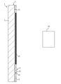
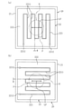
- Samples 20 shown in FIGS. 6 and 7 were prepared as samples corresponding to the base 2 of the radome for the vehicle-mounted radar device of the present invention and the base 2 of the radome 1 for the vehicle-mounted radar device of the above embodiment, and the sample 20 was used to transmit electromagnetic waves.
- An experiment to verify the rate and an experiment to verify the snow melting property were conducted.
- the sample 20 is composed of a base material 21 corresponding to the base material 3, a heater sheet 22 corresponding to the heater sheet 4, and a double-sided tape 23 corresponding to the adhesive layer 5, and the side of the base material 21 to which the electromagnetic wave is irradiated.
- the double-sided tape 23 and the heater sheet 22 are laminated in this order on the back surface side or the inner surface side, and the heater sheet 22 is fixed to the base material 21 via the double-sided tape 23.
- the base material 21 is a flat plate with a thickness of 2.2 mm
- the double-sided tape 23 is a flat surface with a thickness of 0.1 mm
- the heater sheet 22 is a flat surface with a thickness of 0.1 mm.
- the total thickness is 2.4 mm.
- the base material 21 was a resin plate made of ABS resin, and more specifically, it was formed of a heat-resistant ABS resin (MTH-2) manufactured by Nippon A & L Inc.
- MTH-2 heat-resistant ABS resin
- the complex permittivity ⁇ 'for electromagnetic waves (millimeter waves) in the 76/77 GHz band at room temperature (about 25 ° C.) of this ABS (MTH-2) is 2.656
- the dielectric loss tan ⁇ is 0.0065.
- the heater sheet 22 is configured such that the heater wire 221 and its terminal 2212 are exposed on the back surface side of the insulating film 222, and the heater wire 221 is embedded in the insulating film 222.
- the insulating film 222 was a polyimide film, and the heater wire 221 was a copper wire (resistivity 1.69 ⁇ 10-8 ⁇ ⁇ m).
- the complex permittivity ⁇ 'for electromagnetic waves (millimeter waves) in the 76/77 GHz band is 3.247, and the dielectric loss tan ⁇ is 0.0054.
- the heater wire 221 meanders along the insulating film 222, is wired so as to be folded back, and extends in a series, and straight portions 2211 are arranged side by side at intervals along the insulating film 222. ..
- the pitch P between the straight portions 2211 and 2211 of the heater wire 221 of the sample 20 is 7.0 mm, and the pitch P between the straight portions 2211 and 2211 is the same.
- the double-sided tape 23 is made of an acrylic adhesive without a core material, and has a complex dielectric constant ⁇ 'for electromagnetic waves (millimeter waves) in the 76/77 GHz band at room temperature (about 25 ° C) of 2.513 and a dielectric loss tan ⁇ of 0.0139. be.
- the measurement of the experiment for verifying the electromagnetic wave transmittance using the sample 20 was carried out using the Quality Automobile Radome Tester (QAR) manufactured by ROHDE & SCHWARZ as a measuring device.
- QAR Quality Automobile Radome Tester
- 101 is an electromagnetic wave transmitting unit
- 102 is a receiving unit
- 103 is an evaluation device.
- the electromagnetic wave transmitted from the electromagnetic wave transmitting unit 101 used for the measurement is a millimeter wave in the 76/77 GHz band.
- EW is the propagation direction of the millimeter wave.
- the sample 20 is irradiated with the electromagnetic wave from the electromagnetic wave transmitting unit 101 so that R shown in FIG. 7 becomes the electromagnetic wave irradiation region, and the polarization plane LP of the linear polarization of the millimeter wave in the 76/77 GHz band is the heater wire of the sample 20.
- the electromagnetic wave transmission rate is measured when the electromagnetic wave is irradiated so as to be perpendicular to the linear portion 2211 of the 221 (see FIG. 7A), and the polarization plane of the linear polarization of the millimeter wave in the 76/77 GHz band.
- the electromagnetic wave transmission rate was measured when the LP was irradiated with the electromagnetic wave so as to be parallel to the straight portion 2211 of the heater wire 221 of the sample 20 (see FIG. 7 (b)).
- the straight portion is maintained at a pitch of 7.0 mm.
- the measurement was performed without energizing the heater wire 221 while changing the line width W of the 2211 to change the occupancy rate of the heater wire 221 or its straight line portion 2211 occupying the entire area of the electromagnetic wave irradiation region R.
- the measurement result is shown in FIG.
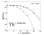
- the polarization plane LP of the linearly polarized wave of the electromagnetic wave is set to the linear portion 2211 of the heater wire 221. It can be seen that in the structure of irradiating vertically with respect to the substrate 21, the surface occupancy rate of the straight portion 2211 of the heater wire 221 in the electromagnetic wave irradiation region R of the base material 21 can be set to 24% or less.
- the surface occupancy rate of the linear portion 2211 of the heater wire 221 in the electromagnetic wave irradiation region R of the base material 21 is determined. It can be seen that the same permissible value can be achieved by setting it to 16% or less.
- the polarization plane LP of the linearly polarized wave of the electromagnetic wave is set with respect to the linear portion 2211 of the heater wire 221. It can be seen that the structure can be achieved by setting the surface occupancy rate of the linear portion 2211 of the heater wire 221 in the electromagnetic wave irradiation region R of the base material 21 to 20% or less.
- the surface occupancy rate of the linear portion 2211 of the heater wire 221 in the electromagnetic wave irradiation region R of the base material 21 is determined. It can be seen that the same permissible value can be achieved by setting it to 13% or less.
- the surface occupancy ratio of the linear portion 2211 of the heater wire 221 in the electromagnetic wave irradiation region R of the base material 21 is increased.
- the electromagnetic wave transmission rate is -0.4 dB or more when the electromagnetic wave transmission rate is 10% or less, and the surface occupancy rate of the straight portion 2211 of the heater wire 221 in the electromagnetic wave irradiation region R of the base material 21 is 7.5% or less, the electromagnetic wave transmission rate is-. It can be seen that a very high electromagnetic wave transmission rate of 0.35 dB or more can be realized.
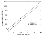
- the sample 20 was installed on the front surface of the vehicle with the traveling direction of the vehicle as the front side, and the heater wire 221 of the sample 20 was energized with an input voltage of 10 V, and the speed of the vehicle was set.
- the line width W of the straight line portion 2211 is changed to change the occupancy rate of the heater wire 221 or the straight line portion 2211 occupying the entire area of the electromagnetic wave irradiation region R, and the environmental temperature-.
- the experiment was conducted by setting the case of 5 ° C and the case of the environmental temperature of -15 ° C. The measurement result is shown in FIG.
- the surface occupancy rate of the straight portion 2211 of the heater wire 221 in the electromagnetic wave irradiation region R of the base material 21 is set to 1% or more.
- the temperature of the outer surface (front surface in the vehicle traveling direction) of the base material 21 can be set to a state of exceeding 0 ° C.
- the surface occupancy rate of the straight portion 2211 of the heater wire 221 in the electromagnetic wave irradiation region R of the base material 21 should be set to 3% or more. Therefore, it can be seen that the temperature of the outer surface (front surface in the vehicle traveling direction) of the base material 21 can be set to a state of more than 0 ° C.
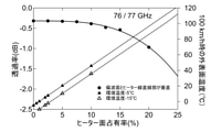
- FIG. 10 shows the surface occupancy rate and electromagnetic wave transmittance of the heater wire 221 and the outer surface of the sample 20 when the sample 20 is irradiated with the polarization plane LP of the linearly polarized wave of the electromagnetic wave perpendicular to the straight line portion 2211 of the heater wire 221.
- the relationship of temperature is shown.
- the heater wire 221 exhibits a practical snow melting function while clearing the required electromagnetic wave transmittance.
- the lower limit of the surface occupancy of the linear portion 2211 is preferably 1% or more, more preferably 3% or more, and the upper limit is preferably 24% or less, more preferably 20% or less.
- the upper limit of the surface occupancy of the heater wire 221 or the straight portion 2211 thereof is more preferably 10% or less, and even more preferably 7.5% or less. Is.
- FIG. 11 shows the surface occupancy rate and electromagnetic wave transmittance of the heater wire 221 and the outer surface of the sample 20 when the sample 20 is irradiated with the polarization plane LP of the linearly polarized wave of the electromagnetic wave parallel to the linear portion 2211 of the heater wire 221. Shows the relationship between temperatures.
- the heater wire 221 exhibits a practical snow melting function while clearing the required electromagnetic wave transmittance.
- the lower limit of the surface occupancy of the linear portion 2211 is preferably 1% or more, more preferably 3% or more, and the upper limit is preferably 16% or less, more preferably 13% or less.
- the radome for an in-vehicle radar device of the present invention appropriately includes a radome having an electromagnetic wave transmitting base material and a base material having a heater wire laminated on the inner surface side of the base material and wired in the surface direction of the base material.
- a radome having a structure in which heater wires are laminated and arranged on the inner surface side of a base material and directly fixed without using the heater sheet 4 is also included.
- the present invention can be used as a radome for an in-vehicle radar device and an in-vehicle radar structure.
Landscapes
- Engineering & Computer Science (AREA)
- Computer Networks & Wireless Communication (AREA)
- Physics & Mathematics (AREA)
- General Physics & Mathematics (AREA)
- Radar, Positioning & Navigation (AREA)
- Remote Sensing (AREA)
- Details Of Aerials (AREA)
- Radar Systems Or Details Thereof (AREA)
- Vehicle Waterproofing, Decoration, And Sanitation Devices (AREA)
Priority Applications (2)
| Application Number | Priority Date | Filing Date | Title |
|---|---|---|---|
| US18/021,235 US12249759B2 (en) | 2020-08-18 | 2021-06-23 | Radome for vehicle-mounted radar device, and vehicle-mounted radar structure |
| CN202180055923.5A CN116034055A (zh) | 2020-08-18 | 2021-06-23 | 车载雷达装置用天线罩及车载雷达结构 |
Applications Claiming Priority (2)
| Application Number | Priority Date | Filing Date | Title |
|---|---|---|---|
| JP2020-137956 | 2020-08-18 | ||
| JP2020137956A JP7664672B2 (ja) | 2020-08-18 | 2020-08-18 | 車載レーダー装置用レドーム及び車載レーダー構造 |
Publications (1)
| Publication Number | Publication Date |
|---|---|
| WO2022038892A1 true WO2022038892A1 (ja) | 2022-02-24 |
Family
ID=78119541
Family Applications (1)
| Application Number | Title | Priority Date | Filing Date |
|---|---|---|---|
| PCT/JP2021/023881 Ceased WO2022038892A1 (ja) | 2020-08-18 | 2021-06-23 | 車載レーダー装置用レドーム及び車載レーダー構造 |
Country Status (4)
| Country | Link |
|---|---|
| US (1) | US12249759B2 (enExample) |
| JP (2) | JP7664672B2 (enExample) |
| CN (1) | CN116034055A (enExample) |
| WO (1) | WO2022038892A1 (enExample) |
Cited By (1)
| Publication number | Priority date | Publication date | Assignee | Title |
|---|---|---|---|---|
| DE102022115241A1 (de) | 2022-06-20 | 2023-12-21 | Bayerische Motoren Werke Aktiengesellschaft | Verfahren zur Niederschlagsablagerungserkennung an einem Radom und zur Steuerung und/oder Regelung von zumindest einem Heizelement des Radoms, Recheneinrichtung, computerlesbares (Speicher)Medium sowie temperierbares Radarsensorsystem |
Families Citing this family (6)
| Publication number | Priority date | Publication date | Assignee | Title |
|---|---|---|---|---|
| JP7664672B2 (ja) * | 2020-08-18 | 2025-04-18 | 三恵技研工業株式会社 | 車載レーダー装置用レドーム及び車載レーダー構造 |
| JP7724521B2 (ja) * | 2021-06-30 | 2025-08-18 | 東京コスモス電機株式会社 | アンテナカバーの製造方法 |
| JP7537409B2 (ja) * | 2021-10-29 | 2024-08-21 | 豊田合成株式会社 | 電磁波透過カバー及び電磁波透過カバーの製造方法 |
| EP4439112A4 (en) * | 2021-11-24 | 2025-03-19 | Asahi Kasei Kabushiki Kaisha | Radome for radar |
| JP2023110258A (ja) * | 2022-01-28 | 2023-08-09 | 豊田合成株式会社 | 車両用外装品 |
| JPWO2024157867A1 (enExample) * | 2023-01-23 | 2024-08-02 |
Citations (1)
| Publication number | Priority date | Publication date | Assignee | Title |
|---|---|---|---|---|
| JP2003057333A (ja) * | 2001-07-06 | 2003-02-26 | Thales | 特に車両に装備され、レリーフのパターンを表すレーダーを隠す装置及び該装置を含む検知システム |
Family Cites Families (26)
| Publication number | Priority date | Publication date | Assignee | Title |
|---|---|---|---|---|
| US4999639A (en) * | 1989-03-03 | 1991-03-12 | Hazeltine Corporation | Radome having integral heating and impedance matching elements |
| US5528249A (en) * | 1992-12-09 | 1996-06-18 | Gafford; George | Anti-ice radome |
| JP3650953B2 (ja) * | 1998-06-29 | 2005-05-25 | 株式会社村田製作所 | 誘電体レンズアンテナおよびそれを用いた無線装置 |
| DE19963004A1 (de) * | 1999-12-24 | 2001-06-28 | Bosch Gmbh Robert | Kraftfahrzeug-Radarsystem |
| US7839305B1 (en) | 2004-02-12 | 2010-11-23 | Wallach Morton L | Smart sensor systems—submarine marking and sonar detection |
| DE102004049148A1 (de) * | 2004-10-07 | 2006-04-13 | Rehau Ag + Co | Heizungselement auf einer polymeren Innenoberfläche eines Frontmoduls/Stoßfängers eines Kraftfahrzeuges in Wirkverbindung mit einer Radarsende- und - empfangseinheit |
| JP6467985B2 (ja) * | 2015-02-25 | 2019-02-13 | 豊田合成株式会社 | 電磁波透過カバーの製造方法 |
| US20170008473A1 (en) * | 2015-07-08 | 2017-01-12 | Lacks Enterprises, Inc. | Bonded laminate vehicle grill structure |
| JP6681562B2 (ja) | 2016-03-31 | 2020-04-15 | 大日本印刷株式会社 | 転写用ハードコートフィルム、及びこれを用いた加飾部材 |
| US10651530B2 (en) * | 2016-06-01 | 2020-05-12 | Toyoda Gosei Co., Ltd. | Decorative component for vehicle |
| JP2018066705A (ja) | 2016-10-21 | 2018-04-26 | 豊田合成株式会社 | 車両用装飾部品 |
| JP6652031B2 (ja) | 2016-10-21 | 2020-02-19 | 豊田合成株式会社 | 車両用装飾部品及びその製造方法 |
| CN113696830B (zh) * | 2016-10-21 | 2024-06-14 | 丰田合成株式会社 | 用于车辆的装饰件及其制造方法 |
| WO2019065165A1 (ja) * | 2017-09-28 | 2019-04-04 | 豊田合成株式会社 | 車両用装飾部品 |
| FR3080318B1 (fr) * | 2018-04-19 | 2021-10-22 | Plastic Omnium Cie | Procede de fabrication d'un element pour piece de carrosserie comportant des moyens de degivrage perfectionnes |
| JP6719506B2 (ja) * | 2018-06-26 | 2020-07-08 | Nissha株式会社 | 電磁波透過性カバー及びその製造方法 |
| JP7094911B2 (ja) * | 2019-03-07 | 2022-07-04 | 三恵技研工業株式会社 | 車載レーダー装置用レドーム |
| JP7312608B2 (ja) * | 2019-05-23 | 2023-07-21 | 豊田合成株式会社 | 車両用装飾部品 |
| CN110635241B (zh) * | 2019-09-11 | 2024-04-09 | 宁波信泰机械有限公司 | 一种汽车可加热雷达罩结构及其生产方法 |
| DE102020001286A1 (de) * | 2020-02-28 | 2021-09-02 | HELLA GmbH & Co. KGaA | Beheizbares Kunststoffbauteil und Verfahren zu dessen Herstellung |
| JP2021174690A (ja) * | 2020-04-27 | 2021-11-01 | 豊田合成株式会社 | ヒータシート及び車載センサカバー |
| JP7618410B2 (ja) * | 2020-08-04 | 2025-01-21 | 三恵技研工業株式会社 | 車載レーダー装置用レドーム構造及びその製造方法 |
| JP7664672B2 (ja) * | 2020-08-18 | 2025-04-18 | 三恵技研工業株式会社 | 車載レーダー装置用レドーム及び車載レーダー構造 |
| JP7334713B2 (ja) * | 2020-11-24 | 2023-08-29 | トヨタ自動車株式会社 | 電磁波透過性ヒータ |
| JP7100327B1 (ja) * | 2021-04-19 | 2022-07-13 | 南部化成株式会社 | ヒーター内蔵車両用エンブレムおよびその製造方法 |
| JP2023110258A (ja) * | 2022-01-28 | 2023-08-09 | 豊田合成株式会社 | 車両用外装品 |
-
2020
- 2020-08-18 JP JP2020137956A patent/JP7664672B2/ja active Active
-
2021
- 2021-06-23 WO PCT/JP2021/023881 patent/WO2022038892A1/ja not_active Ceased
- 2021-06-23 US US18/021,235 patent/US12249759B2/en active Active
- 2021-06-23 CN CN202180055923.5A patent/CN116034055A/zh active Pending
-
2025
- 2025-02-17 JP JP2025023549A patent/JP7755762B2/ja active Active
Patent Citations (1)
| Publication number | Priority date | Publication date | Assignee | Title |
|---|---|---|---|---|
| JP2003057333A (ja) * | 2001-07-06 | 2003-02-26 | Thales | 特に車両に装備され、レリーフのパターンを表すレーダーを隠す装置及び該装置を含む検知システム |
Non-Patent Citations (1)
| Title |
|---|
| IKEMASU RYUHO, KOBAYASHI HIROYUKI, YAMAMOTO SHINPEI, TAKAKUSAKI MAKOTO, SATO DAISUKE, HASEGAWA DAIJI: "Optimum Pattern of Heater Element for Radome Achieving Enough Heating Ability and Millimeter Wave Transmissivity", TRANSACTIONS OF SOCIETY OF AUTOMOTIVE ENGINEERS OF JAPAN, vol. 51, no. 2, 1 March 2020 (2020-03-01), pages 323 - 327, XP055909144 * |
Cited By (1)
| Publication number | Priority date | Publication date | Assignee | Title |
|---|---|---|---|---|
| DE102022115241A1 (de) | 2022-06-20 | 2023-12-21 | Bayerische Motoren Werke Aktiengesellschaft | Verfahren zur Niederschlagsablagerungserkennung an einem Radom und zur Steuerung und/oder Regelung von zumindest einem Heizelement des Radoms, Recheneinrichtung, computerlesbares (Speicher)Medium sowie temperierbares Radarsensorsystem |
Also Published As
| Publication number | Publication date |
|---|---|
| JP2025065542A (ja) | 2025-04-17 |
| US12249759B2 (en) | 2025-03-11 |
| JP2021169993A (ja) | 2021-10-28 |
| CN116034055A (zh) | 2023-04-28 |
| JP7755762B2 (ja) | 2025-10-16 |
| JP7664672B2 (ja) | 2025-04-18 |
| US20230299472A1 (en) | 2023-09-21 |
Similar Documents
| Publication | Publication Date | Title |
|---|---|---|
| WO2022038892A1 (ja) | 車載レーダー装置用レドーム及び車載レーダー構造 | |
| JP7094911B2 (ja) | 車載レーダー装置用レドーム | |
| JP7313106B2 (ja) | 車載レーダー装置用レドーム | |
| Xu et al. | Cross-wavelength invisibility integrated with various invisibility tactics | |
| JP2021169993A5 (enExample) | ||
| Xie et al. | Heat resisting metallic meta‐skin for simultaneous microwave broadband scattering and infrared invisibility based on catenary optical field | |
| US20180269559A1 (en) | Radome provided with a resistive heating system formed from strips of metal nanoelements | |
| EP1647172B1 (en) | Electromagnetic radiation absorber | |
| JP6684274B2 (ja) | 電磁遮蔽用加熱ガラスパネル | |
| Jiang et al. | Dispersion engineering of metasurfaces for dual-frequency quasi-three-dimensional cloaking of microwave radiators | |
| Geng et al. | Flexible and Dual‐Tunable Radar Absorber Enabled by Graphene | |
| Tak et al. | Metamaterial absorbers for 24-GHz automotive radar applications | |
| JP7336619B1 (ja) | 融雪レドーム | |
| CN117241568A (zh) | 电磁波屏蔽件 | |
| WO2021206022A1 (ja) | フィルムヒータ | |
| JP2019066231A (ja) | 電波透過カバー | |
| Hasan et al. | Left‐handed meta‐surface loaded with ring resonator modelling for satellite application | |
| Chen et al. | Method of tapered resistive sheet loading for controlling edge scattering | |
| Lee et al. | Design of electromagnetic wave absorbing sandwich composite for secondary bonding application | |
| JP2023178166A (ja) | 融雪レドーム | |
| Wang et al. | Left-handed material superstrate applied to the RCS reduction of microstrip antenna | |
| JP2025150774A (ja) | 車載レーダー装置用レドーム及びその製造方法 | |
| CN113557802A (zh) | 电波吸收体及电波吸收体用套件 | |
| WO2021205811A1 (ja) | フィルムヒータ | |
| Gu et al. | PCB prism absorber design and characterisation |
Legal Events
| Date | Code | Title | Description |
|---|---|---|---|
| 121 | Ep: the epo has been informed by wipo that ep was designated in this application |
Ref document number: 21858042 Country of ref document: EP Kind code of ref document: A1 |
|
| NENP | Non-entry into the national phase |
Ref country code: DE |
|
| 122 | Ep: pct application non-entry in european phase |
Ref document number: 21858042 Country of ref document: EP Kind code of ref document: A1 |
|
| WWG | Wipo information: grant in national office |
Ref document number: 18021235 Country of ref document: US |