WO2022030416A1 - 鉛合金、鉛蓄電池用正極、鉛蓄電池、及び蓄電システム - Google Patents
鉛合金、鉛蓄電池用正極、鉛蓄電池、及び蓄電システム Download PDFInfo
- Publication number
- WO2022030416A1 WO2022030416A1 PCT/JP2021/028490 JP2021028490W WO2022030416A1 WO 2022030416 A1 WO2022030416 A1 WO 2022030416A1 JP 2021028490 W JP2021028490 W JP 2021028490W WO 2022030416 A1 WO2022030416 A1 WO 2022030416A1
- Authority
- WO
- WIPO (PCT)
- Prior art keywords
- lead
- positive electrode
- less
- mass
- alloy
- Prior art date
- Legal status (The legal status is an assumption and is not a legal conclusion. Google has not performed a legal analysis and makes no representation as to the accuracy of the status listed.)
- Ceased
Links
Images


Classifications
-
- C—CHEMISTRY; METALLURGY
- C22—METALLURGY; FERROUS OR NON-FERROUS ALLOYS; TREATMENT OF ALLOYS OR NON-FERROUS METALS
- C22C—ALLOYS
- C22C11/00—Alloys based on lead
- C22C11/06—Alloys based on lead with tin as the next major constituent
-
- H—ELECTRICITY
- H01—ELECTRIC ELEMENTS
- H01M—PROCESSES OR MEANS, e.g. BATTERIES, FOR THE DIRECT CONVERSION OF CHEMICAL ENERGY INTO ELECTRICAL ENERGY
- H01M4/00—Electrodes
- H01M4/02—Electrodes composed of, or comprising, active material
- H01M4/14—Electrodes for lead-acid accumulators
-
- C—CHEMISTRY; METALLURGY
- C22—METALLURGY; FERROUS OR NON-FERROUS ALLOYS; TREATMENT OF ALLOYS OR NON-FERROUS METALS
- C22F—CHANGING THE PHYSICAL STRUCTURE OF NON-FERROUS METALS AND NON-FERROUS ALLOYS
- C22F1/00—Changing the physical structure of non-ferrous metals or alloys by heat treatment or by hot or cold working
- C22F1/12—Changing the physical structure of non-ferrous metals or alloys by heat treatment or by hot or cold working of lead or alloys based thereon
-
- H—ELECTRICITY
- H01—ELECTRIC ELEMENTS
- H01M—PROCESSES OR MEANS, e.g. BATTERIES, FOR THE DIRECT CONVERSION OF CHEMICAL ENERGY INTO ELECTRICAL ENERGY
- H01M10/00—Secondary cells; Manufacture thereof
- H01M10/06—Lead-acid accumulators
- H01M10/12—Construction or manufacture
-
- H—ELECTRICITY
- H01—ELECTRIC ELEMENTS
- H01M—PROCESSES OR MEANS, e.g. BATTERIES, FOR THE DIRECT CONVERSION OF CHEMICAL ENERGY INTO ELECTRICAL ENERGY
- H01M10/00—Secondary cells; Manufacture thereof
- H01M10/06—Lead-acid accumulators
- H01M10/18—Lead-acid accumulators with bipolar electrodes
-
- H—ELECTRICITY
- H01—ELECTRIC ELEMENTS
- H01M—PROCESSES OR MEANS, e.g. BATTERIES, FOR THE DIRECT CONVERSION OF CHEMICAL ENERGY INTO ELECTRICAL ENERGY
- H01M4/00—Electrodes
- H01M4/02—Electrodes composed of, or comprising, active material
- H01M2004/026—Electrodes composed of, or comprising, active material characterised by the polarity
- H01M2004/028—Positive electrodes
-
- Y—GENERAL TAGGING OF NEW TECHNOLOGICAL DEVELOPMENTS; GENERAL TAGGING OF CROSS-SECTIONAL TECHNOLOGIES SPANNING OVER SEVERAL SECTIONS OF THE IPC; TECHNICAL SUBJECTS COVERED BY FORMER USPC CROSS-REFERENCE ART COLLECTIONS [XRACs] AND DIGESTS
- Y02—TECHNOLOGIES OR APPLICATIONS FOR MITIGATION OR ADAPTATION AGAINST CLIMATE CHANGE
- Y02E—REDUCTION OF GREENHOUSE GAS [GHG] EMISSIONS, RELATED TO ENERGY GENERATION, TRANSMISSION OR DISTRIBUTION
- Y02E60/00—Enabling technologies; Technologies with a potential or indirect contribution to GHG emissions mitigation
- Y02E60/10—Energy storage using batteries
Definitions
- the present invention relates to a lead alloy, a positive electrode for a lead storage battery, a lead storage battery, and a power storage system.
- the positive electrode of the lead storage battery includes a lead layer for a positive electrode formed of a lead alloy and an active material arranged on the surface of the lead layer for a positive electrode.
- Conventional positive electrodes for lead-acid batteries are made of well-known lead or lead alloys.
- the lead layer for the positive electrode is gradually corroded. At this time, corrosion progressed along the grain boundaries of the crystal grains of the lead alloy used for the lead layer for the positive electrode, and the corrosion may penetrate the lead layer for the positive electrode in the thickness direction.
- the lead layer for the positive electrode is thinned in order to reduce the weight of the battery, improve the utilization rate of the volume in the battery, reduce the amount of lead used, and the like, this problem becomes more remarkable. When such penetration occurs, the conduction path of electricity is cut off, the internal resistance of the battery increases, and there is a risk that the predetermined characteristics cannot be exhibited.
- the formation of through holes in the lead layer for the positive electrode further promotes corrosion to other members, so that the electrolytic solutions on the positive electrode side and the negative electrode side wrap around each other, so-called liquid entrainment.
- the battery characteristics would deteriorate due to the phenomenon called, and in the worst case, it would not be usable.
- the present invention relates to a lead alloy capable of suppressing the progress of intergranular corrosion, a lead layer for a positive electrode in which penetration in the thickness direction is unlikely to occur due to corrosion even if the thickness is suppressed, a positive electrode for a lead storage battery using the lead layer, and the lead storage battery.
- An object of the present invention is to provide a lead-acid battery and a power storage system, which are configured by using a positive electrode for use and can prolong the life of a lead-acid battery in which an increase in internal resistance does not easily occur.
- the lead alloy according to one aspect of the present invention contains 0.4% by mass or more and 2% by mass or less of tin and 0.004% by mass or less of bismuth, and the balance is composed of lead and unavoidable impurities, and is electron backscattered.
- the crystal orientation distribution map created by analyzing the surface by the diffraction method is image-analyzed to extract the intersection of the orientation difference boundary between crystal grains having a crystal orientation difference of 5 ° or more and a straight line extending in a specific direction.
- the gist is that the average value of the above distances is 50 ⁇ m or less when the distance between two adjacent intersections among the extracted intersections is measured.
- the lead alloy according to another aspect of the present invention contains 0.4% by mass or more and 2% by mass or less of tin and 0.004% by mass or less of bismuth, and 0.1% by mass or less of calcium and 0.
- the crystal orientation distribution map created by analyzing the surface by electron backscatter diffraction method which further contains at least one of silver of 1% by mass or less and the balance is composed of lead and unavoidable impurities, is analyzed by image analysis.
- the intersection of the orientation difference boundary between crystal grains having a crystal orientation difference of 5 ° or more and a straight line extending in a specific direction is extracted, and the distance between two adjacent intersections of the extracted intersections is measured.
- it is a gist that the average value of the above distance is 50 ⁇ m or less. More preferably, the average value of the distance is 30 ⁇ m or less.
- the positive electrode for a lead storage battery according to still another aspect of the present invention is arranged on the surface of the lead layer for a positive electrode formed of the lead alloy according to the above aspect or another aspect and the lead layer for a positive electrode.
- the gist is that the lead layer for the positive electrode is provided with an active material and the thickness of the lead layer for the positive electrode is 0.5 mm or less.
- the lead storage battery according to still another aspect of the present invention includes a positive electrode for a lead storage battery according to still another aspect.
- the power storage system according to still another aspect of the present invention includes the lead storage battery according to still another aspect and is a power storage system for storing electricity in the lead storage battery.
- a lead alloy capable of preventing corrosion that penetrates the lead layer for a positive electrode in the thickness direction even if the thickness is suppressed a positive electrode for a lead storage battery formed of the lead alloy, and a positive electrode for a lead storage battery are used. It is possible to provide a lead-acid battery and a power storage system in which an increase in internal resistance is unlikely to occur.
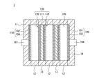
- the lead-acid battery 1 shown in FIG. 1 is a bipolar lead-acid battery, in which a first plate unit in which a negative electrode 110 is fixed to a flat plate-shaped first plate 11 and an electrolytic layer 105 are fixed to a frame plate-shaped second plate 12.
- the negative electrode terminal 107 is fixed to the first plate 11 in a state of being electrically connected to the negative electrode 110 fixed to the first plate 11.
- the positive electrode terminal 108 is fixed to the fourth plate 14 in a state of being electrically connected to the positive electrode 120 fixed to the fourth plate 14.
- the second plate unit and the third plate unit may be provided with an arbitrary number of stages alternately according to a desired storage capacity.
- the first to fourth plates 11, 12, 13, 14 and the substrate 111 are made of, for example, a well-known molding resin.
- the electrolytic layer 105 is made of, for example, a glass fiber mat impregnated with an electrolytic solution such as sulfuric acid.
- the negative electrode 110 is composed of, for example, a lead layer 102 for a negative electrode made of a well-known lead foil and an active material layer 104 for a negative electrode.
- the positive electrode 120 is composed of a lead layer 101 for a positive electrode and an active material layer 103 for a positive electrode, which are made of the lead alloy foil of the present embodiment described later.
- the positive electrode 120 and the negative electrode 110 are fixed to the front surface and the back surface of the substrate 111, respectively, and are electrically connected by an appropriate method.
- the positive electrode 120 and the negative electrode 110 may be fixed to one surface of the two substrates 111, respectively, and the other surfaces may be electrically connected and fixed to each other.
- the plates 11 to 14 are fixed to each other so that the inside is sealed by an appropriate method so that the electrolytic solution does not flow out.
- the substrate 111, the lead layer 101 for the positive electrode, the active material layer 103 for the positive electrode, the lead layer 102 for the negative electrode, and the active material layer 104 for the negative electrode are used for the lead-acid battery.
- a bipolar electrode 130, which is an electrode, is configured.
- the bipolar electrode is an electrode having both positive and negative functions with one electrode.
- a plurality of cells having an electrolytic layer 105 interposed between the positive electrode 120 having the positive electrode active material layer 103 and the negative electrode 110 having the negative electrode active material layer 104 are alternately laminated. By assembling them together, the battery configuration is such that the cells are connected in series.
- a bipolar lead storage battery provided with a bipolar electrode having both positive and negative electrode functions with one electrode is shown as an example of the lead storage battery, but the lead storage battery of the present embodiment has the function of a positive electrode.
- a lead storage battery may be a lead storage battery in which an electrode having a positive electrode and an electrode having a function of a negative electrode are provided, respectively, and both positive electrode and negative electrode, which are separate electrodes, are alternately arranged.
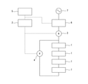
- a power storage system can be configured by using the lead storage battery 1 of the present embodiment shown in FIG.
- An example of the power storage system is shown in FIG.
- the power storage system of FIG. 2 is composed of a plurality of (four in the example of FIG. 2) lead storage batteries 1, 1, ... Connected in series, and AC / DC conversion (AC) during charging and discharging of the assembled batteries.
- An AC / DC converter 6 that performs exchange between electric power and DC electric power, and a current sensor 3 that is installed between the assembled battery and the AC / DC converter 6 and measures the charge / discharge current during charging and discharging of the assembled battery.
- a voltage sensor 4 that measures the voltage of the battery, and a storage status monitoring device that receives measurement data transmitted from the current sensor 3 and the voltage sensor 4 and performs status determination and alarm determination of the assembled battery based on the received measurement data.
- Energy that receives the storage status information transmitted by the storage status monitoring device 2 based on the results of the executed status determination and alarm determination, and determines whether to charge or discharge the assembled battery based on the received storage status information. It is equipped with a management system 5.
- the energy management system 5 determines whether to charge or discharge the assembled battery based on the storage status information received from the storage status monitoring device 2, and transmits a signal instructing the execution of charging or discharging to the AC / DC conversion device 6.
- the AC / DC converter 6 Upon receiving the signal instructing the execution of discharge, the AC / DC converter 6 converts the DC power discharged from the assembled battery into AC power and outputs it to the commercial power system 7.
- the AC / DC conversion device 6 converts the AC power input from the commercial power system 7 into DC power to charge the assembled battery.
- the number of lead-acid batteries 1 in series is determined by the input voltage range of the AC / DC converter 6.
- the thickness of the lead layer 101 for the positive electrode is set to 0.5 mm or less.
- the lead layer 101 for the positive electrode is formed of a lead alloy that satisfies the following two conditions A and B so that the problem of growth is unlikely to occur even with such a thickness.
- the lead layer 101 for the positive electrode is formed of the above-mentioned lead alloy
- the internal resistance is unlikely to increase. That is, since the lead layer 101 for the positive electrode is formed of the above-mentioned lead alloy, the progress of intergranular corrosion is suppressed and penetration in the thickness direction is unlikely to occur. This prevents the conduction path of electricity from being disrupted. Therefore, when used as a battery, it is possible to achieve the effect that the internal resistance is unlikely to increase. It will be described in more detail below.
- the tin content is more preferably 0.7% by mass or more, further preferably 1.0% by mass or more, particularly preferably 1.3% by mass or more, and 1.6% by mass. The above is the most preferable. When the tin content is in such a range, an orientation difference boundary is likely to be formed in the lead alloy.
- the calcium content is more preferably 0.07% by mass or less, more preferably 0.04% by mass or less, in order to further suppress the occurrence of corrosion penetrating the lead layer for the positive electrode in the thickness direction. It is more preferable, and it is particularly preferable that it is 0.02% by mass or less.
- the silver content is more preferably 0.03% by mass or less in order to suppress the separation of the silver phase and improve the corrosion resistance of the lead alloy.
- Calcium and silver may be positively added to the lead alloy, but even if they are not positively added, they may be contained as unavoidable impurities due to contamination from the bare metal.
- the maximum amount that can be contained as an unavoidable impurity is 0.012% by mass for both calcium and silver.
- the lead alloy contains bismuth, the formability due to rolling of the lead alloy tends to decrease. That is, bismuth is one of the impurities preferably not contained in the lead alloy of the present embodiment as much as possible. Therefore, the content of bismuth in the lead alloy needs to be 0.004% by mass or less, and most preferably 0% by mass. However, considering the cost of the lead alloy, the content of bismuth is preferably 0.0004% by mass or more.
- lead alloys may contain elements other than lead, tin, calcium, silver and bismuth.
- This element is an impurity inevitably contained in the lead alloy, and the total content of elements other than lead, tin, calcium, silver and bismuth in the lead alloy is preferably 0.01% by mass or less. , 0% by mass is most preferable.
- the lead alloy of the present embodiment forming the lead layer 101 for the positive electrode contains tin of 0.4% by mass or more and 2% by mass or less and bismuth of 0.004% by mass or less, and the balance is lead. It is a lead alloy composed of unavoidable impurities, or contains 0.4% by mass or more and 2% by mass or less of tin and 0.004% by mass or less of bismuth, and 0.1% by mass or less of calcium and 0. It is a lead alloy containing at least one of 1% by mass or less of silver, and the balance is lead and unavoidable impurities.
- the lead alloy of the present embodiment preferably does not contain bismuth as an impurity, but if it does, the content of the lead alloy must be 0.004% by mass or less.
- the lead alloy of the present embodiment contains elements other than lead, tin, calcium, silver and bismuth as unavoidable impurities, the total content thereof is preferably 0.01% by mass or less. ..
- the lead layer for the positive electrode formed of the conventional lead alloy is reduced in order to increase the amount of the active material arranged on the surface, the lead layer for the positive electrode is corroded and has coarse crystal grains. The boundaries were corroded, and corrosion that penetrated the lead layer for the positive electrode in the thickness direction was likely to occur. As a result, the internal resistance of the lead-acid battery may increase. In addition, there is a risk of liquid entanglement between the positive electrode and the negative electrode.
- the intersections of the orientation difference boundaries between the crystal grains having a crystal orientation difference of 5 ° or more and the straight line extending in a specific direction are extracted, and two adjacent intersections are extracted.
- the distance between the intersections was measured, it was found that by setting the average value of the above distances to 50 ⁇ m or less, it is possible to suppress the progress of such corrosion and prevent penetration. That is, since the lattice defects are dense in the grain boundaries between particles having a crystal orientation difference of 5 ° or more, it is considered that a low-key element such as Sn is likely to be concentrated and easily becomes a starting site for corrosion. Therefore, conversely, if a large number of corrosion origin sites are provided, the concentration of low-key elements at each corrosion origin site can be suppressed to a low level, and the progress of corrosion from each corrosion origin site can be suppressed. be able to.
- the lead alloy of the present embodiment has fine crystal grains having a particle size of 0.1 ⁇ m or more and 50 ⁇ m or less, for example, by devising the alloy composition and the manufacturing method (example of the present invention in FIG. 3).
- the alloy composition and the manufacturing method (example of the present invention in FIG. 3).
- the lead layer for the positive electrode of the positive electrode for a lead storage battery is formed from the lead alloy of the present embodiment, a lead storage battery in which an increase in internal resistance is unlikely to occur can be obtained.
- the lead layer 101 for the positive electrode of the positive electrode for the lead storage battery is formed from the lead alloy of the present embodiment, even if the lead layer for the positive electrode is thin, corrosion that penetrates the lead layer for the positive electrode in the thickness direction occurs. Hateful. Therefore, if the lead layer for the positive electrode is formed from the lead alloy of the present embodiment, the thickness of the lead layer for the positive electrode can be reduced to 0.5 mm or less, and the battery capacity can be increased by that amount.
- a positive electrode having a thickness of 1 mm is conventionally applied to a lead layer for a positive electrode having a thickness of 1 mm to form a positive electrode
- a lead layer for a positive electrode having a thickness of 0.2 mm is coated with an active material having a thickness of 1.8 mm. If the positive electrode is formed by applying the above, the amount of the active material is increased by 1.8 times, so that the battery capacity can be increased by about 1.8 times with the same thickness of the positive electrode.
- the lead-acid battery is a bipolar lead-acid battery
- the bipolar lead-acid battery has a low internal resistance and can be used at a higher C rate than a conventional lead-acid battery having a high internal resistance. Therefore, the size of the lead storage battery can be reduced. If the size of a lead-acid battery is small, the size of a container or the like can be reduced when applied to an industrial battery. Therefore, the merit is particularly large when the lead storage battery is buried in the ground. Further, when it is used for mobility of an automobile or the like, the weight of the automobile or the like can be reduced, which leads to improvement of fuel efficiency and can reduce the space for mounting a lead storage battery in the automobile or the like.
- the lead layer for the positive electrode can be made thin, the lead storage battery can be made lighter. Therefore, it is possible to facilitate the laying work of the lead storage battery. If the thickness of the lead layer 101 for the positive electrode is 0.37 mm or less, more preferably 0.25 mm or less, the effect of the present invention that the increase in internal resistance is unlikely to occur is more likely to be exhibited.
- the average grain size of the crystal grains of the lead alloy is an image of the crystal orientation distribution map created by analyzing the surface of the lead alloy by the electron backscatter diffraction method. It can be evaluated by analysis.
- the method for evaluating the average particle size of the crystal grains of the lead alloy is based on the case where the rolled surface of the rolled foil produced by rolling the lead alloy is analyzed by the electron backscatter diffraction method, with reference to FIG. explain.
- RD means the rolling direction of the rolled foil
- TD means the rolling perpendicular direction (width direction) of the rolled foil.
- FIG. 4 is a black-and-white image, crystal grains having different crystal orientations are displayed in different shades of gray (gray scale), and the orientation difference boundary is displayed between the crystal grains having a crystal orientation difference of 5 ° or more. ing.
- a straight line extending in a specific direction (hereinafter, also referred to as a "specific straight line”) is set on the crystal orientation distribution map, and the crystal orientation difference between the specific straight line and the crystal orientation is 5 ° or more.
- the extending direction of the specific straight line is not particularly limited and may be set in advance in a desired direction during image analysis.
- the direction may be the same as the rolling direction of the rolled foil, and rolling may be performed. It can also be in the same direction as the direction perpendicular to the rolling of the foil.
- the extending direction of the specific straight line and the rolling direction of the rolled foil are the same direction. That is, the straight line extending in the rolling direction at the substantially central portion of the paper surface in the vertical direction in FIG. 4 is a specific straight line. Further, when image analysis is performed using a plurality of specific straight lines, the extending directions of all the specific straight lines are the same.
- the number of intersections between the specific straight line and the directional difference boundary between the crystal grains having a crystal orientation difference of 5 ° or more is 13.
- a short horizontal line (a short line extending in the direction perpendicular to the rolling direction) orthogonal to the specific straight line indicates the position of the intersection of the specific straight line and the directional difference boundary. Therefore, in the example of FIG. 4, since there are 12 pairs of combinations of two adjacent intersections on a specific straight line, the distance between the two intersections is measured for these 12 pairs and the average value thereof is calculated.
- the average value of the above distances calculated as described above is the average value of the spacing of the directional difference boundaries between the crystal grains, it is possible to evaluate the average particle size of the crystal grains of the lead alloy. That is, when the average value of the distance is small, it means that the average particle size of the crystal grains of the lead alloy is small, and when the average value of the distance is large, the average particle size of the crystal grains of the lead alloy is small. It means big.
- the average value of the above distance is 50 ⁇ m or less, the average particle size of the crystal grains of the lead alloy forming the rolled foil is small, so that corrosion that penetrates the rolled foil in the thickness direction is unlikely to occur. Therefore, if the lead layer for the positive electrode of the lead storage battery electrode is formed from such a rolled foil, the internal resistance of the lead storage battery is unlikely to increase.
- the average value of the distances needs to be 50 ⁇ m or less, but is preferably 30 ⁇ m or less, and more preferably 20 ⁇ m or less.
- the average value of the above distance can be, for example, about 20 ⁇ m immediately after the production of the rolled foil, but it gradually decreases to, for example, 50 ⁇ m because recrystallization of crystal grains may occur during the use of the lead storage battery. In some cases. When the environment in which the lead-acid battery is used is high, recrystallization is likely to occur, so that the average value of the above distances tends to be large.
- the rolling reduction ratio at the time of rolling is preferably 99% or less, more preferably 90% or less, and further preferably 70% or less.
- a heat treatment intermediate heat treatment
- rolling and intermediate heat treatment may be repeated a plurality of times, and in that case, it is preferable to perform intermediate heat treatment at 300 ° C. or higher twice or more.
- An alloy plate made of a lead alloy having the alloy composition shown in Table 1 was produced by melt casting. This alloy plate was heat-treated and rolled to produce a rolled foil.
- the detailed manufacturing method is as follows.
- Example 1 rolling was performed on an alloy plate having a thickness of 1 mm with a rolling reduction of 70%, and the thickness was set to 0.3 mm.
- an intermediate heat treatment at a temperature of 315 ° C. and a time of 30 min was applied to a rolled foil having a thickness of 0.3 mm, and then further rolling was performed with a reduction ratio of 50% to obtain a rolled foil having a thickness of 0.15 mm. rice field.
- Example 8 to 10 rolling was performed on an alloy plate having a thickness of 2 mm, which had been subjected to an intermediate heat treatment (first intermediate heat treatment) at a temperature of 315 ° C. and a time of 30 min, with a rolling reduction of 55%, and the thickness was adjusted. It was set to 0.9 mm.
- first intermediate heat treatment first intermediate heat treatment
- second intermediate heat treatment second intermediate heat treatment
- further rolling was performed with a rolling reduction ratio of 50% to reduce the thickness to 0.
- a rolled foil was obtained at .45 mm.
- Example 11 a 4 mm thick alloy plate subjected to an intermediate heat treatment (first intermediate heat treatment) at a temperature of 315 ° C. and a time of 30 min was rolled with a rolling reduction of 25% to a thickness of 3 mm. did.
- Example 12 a 2 mm-thick alloy plate subjected to an intermediate heat treatment (first intermediate heat treatment) at a temperature of 315 ° C. and a time of 30 min was rolled with a rolling reduction of 50% to a thickness of 1 mm. did.
- Example 13 a 1 mm thick alloy plate subjected to an intermediate heat treatment (first intermediate heat treatment) at a temperature of 315 ° C. and a time of 30 min was rolled with a rolling reduction ratio of 40%, and the thickness was reduced to 0. It was set to 6 mm.
- a rolled foil was obtained at .15 mm.
- Example 14 a 0.4 mm thick alloy plate subjected to an intermediate heat treatment (first intermediate heat treatment) at a temperature of 315 ° C. and a time of 30 min was rolled with a rolling reduction of 50% to determine the thickness. It was set to 0.2 mm.
- a rolled foil was obtained at .15 mm.
- Example 15 a 0.4 mm thick alloy plate subjected to an intermediate heat treatment (first intermediate heat treatment) at a temperature of 315 ° C. and a time of 30 min was rolled with a rolling reduction of 55% to determine the thickness. It was set to 0.18 mm.
- an intermediate heat treatment (second intermediate heat treatment) at a temperature of 315 ° C. and a time of 30 min was applied to a rolled plate having a thickness of 0.18 mm, and then further rolling was performed with a rolling reduction of 17% to reduce the thickness to 0.
- a rolled foil was obtained at .15 mm.
- rolled foil was manufactured according to the conventional manufacturing method. That is, rolling was performed on an alloy plate having a thickness of 1 mm with a rolling reduction of 1 pass at 5%, and the thickness was set to 0.15 mm. Next, a rolled foil having a thickness of 0.15 mm was subjected to heat treatment at a temperature of 315 ° C. and a time of 30 min and aging heat treatment at a temperature of 60 ° C. and a time of 30 min in the order described to obtain a rolled foil. In Comparative Example 4, a rolled foil could not be produced because a defect called edge cracking occurred at the end of the plate during rolling.
- the rolled foil was manufactured according to a method having a low processing cost among the conventional manufacturing methods. That is, rolling was performed on an alloy plate having a thickness of 1 mm with a reduction ratio of 1 pass of 5%, and a rolled foil was obtained with a thickness of 0.15 mm. No heat treatment was applied to Comparative Examples 5 to 8. In Comparative Example 5, a rolled foil could not be produced because a defect called edge cracking occurred at the end of the plate during rolling.
- the average value (unit: ⁇ m) of all the measured distances was calculated.
- the average value of the above distances means the average value of the intervals of the orientation difference boundaries between the crystal grains.
- Table 1 shows the calculation results of the average value of the spacing between the orientation difference boundaries between the crystal grains.
- a bipolar electrode for a bipolar lead-acid battery was produced by using each of the rolled foils of Examples 1 to 15, Comparative Examples 1 to 3 and Comparative Examples 6 to 8 as a lead layer for a positive electrode. Then, a bipolar lead-acid battery was manufactured using the electrode.
- the structure of the electrode and the bipolar lead-acid battery is almost the same as that shown in FIG.
- the active material forming the positive electrode active material layer is lead dioxide, and the thickness of the positive electrode active material layer is 1.8 mm.
- the active material forming the negative electrode active material layer is lead, and the thickness of the negative electrode active material layer is 1.8 mm.
- a charge / discharge cycle test was conducted on the manufactured bipolar lead-acid battery by repeating charging / discharging.
- the C rate of charge / discharge was 0.2 C, and the number of charge / discharge cycles was 1000 cycles.
- the lead-acid battery is said to be less likely to increase in internal resistance.
- Judgment was made, and in Table 1, "OK” was displayed, and when it exceeded 120%, it was judged that the lead-acid battery was prone to increase in internal resistance, and in Table 1, it was displayed as "NG".
- the lead-acid batteries of Examples 1 to 15 are lead-acid batteries in which an increase in internal resistance is unlikely to occur because the average value of the above distances is 50 ⁇ m or less.
- the lead-acid batteries of Comparative Examples 1 to 3 and Comparative Examples 6 to 8 are lead-acid batteries in which an increase in internal resistance is likely to occur because the average value of the distances exceeds 50 ⁇ m.
- Electrolytic layer 111 ... substrate
Landscapes
- Chemical & Material Sciences (AREA)
- Engineering & Computer Science (AREA)
- Manufacturing & Machinery (AREA)
- Chemical Kinetics & Catalysis (AREA)
- Electrochemistry (AREA)
- General Chemical & Material Sciences (AREA)
- Materials Engineering (AREA)
- Mechanical Engineering (AREA)
- Metallurgy (AREA)
- Organic Chemistry (AREA)
- Physics & Mathematics (AREA)
- Thermal Sciences (AREA)
- Crystallography & Structural Chemistry (AREA)
- Cell Electrode Carriers And Collectors (AREA)
- Battery Electrode And Active Subsutance (AREA)
Priority Applications (7)
| Application Number | Priority Date | Filing Date | Title |
|---|---|---|---|
| AU2021321667A AU2021321667A1 (en) | 2020-08-05 | 2021-07-30 | Lead alloy, positive electrode for lead storage batteries, lead storage battery, and power storage system |
| BR112023000877A BR112023000877A2 (pt) | 2020-08-05 | 2021-07-30 | Liga de chumbo, eletrodo positivo para bateria de armazenamento de chumbo, bateria de armazenamento de chumbo e sistema de armazenamento de energia |
| JP2022541516A JP7575462B2 (ja) | 2020-08-05 | 2021-07-30 | 鉛合金圧延箔、鉛蓄電池用正極、鉛蓄電池、及び蓄電システム |
| EP21854057.3A EP4194574A4 (en) | 2020-08-05 | 2021-07-30 | LEAD ALLOY, POSITIVE ELECTRODE FOR LEAD BATTERIES, LEAD BATTERY AND ENERGY STORAGE SYSTEM |
| CN202180056879.XA CN116034175B (zh) | 2020-08-05 | 2021-07-30 | 铅合金、铅蓄电池用正极、铅蓄电池、以及蓄电系统 |
| US18/162,408 US20230170464A1 (en) | 2020-08-05 | 2023-01-31 | Lead Alloy, Positive Electrode for Lead Storage Battery, Lead Storage Battery, and Power Storage System |
| JP2023134641A JP2023162291A (ja) | 2020-08-05 | 2023-08-22 | 鉛合金箔及びその製造方法、鉛蓄電池用正極、鉛蓄電池、並びに蓄電システム |
Applications Claiming Priority (2)
| Application Number | Priority Date | Filing Date | Title |
|---|---|---|---|
| JP2020133406 | 2020-08-05 | ||
| JP2020-133406 | 2020-08-05 |
Related Child Applications (1)
| Application Number | Title | Priority Date | Filing Date |
|---|---|---|---|
| US18/162,408 Continuation US20230170464A1 (en) | 2020-08-05 | 2023-01-31 | Lead Alloy, Positive Electrode for Lead Storage Battery, Lead Storage Battery, and Power Storage System |
Publications (1)
| Publication Number | Publication Date |
|---|---|
| WO2022030416A1 true WO2022030416A1 (ja) | 2022-02-10 |
Family
ID=80118071
Family Applications (1)
| Application Number | Title | Priority Date | Filing Date |
|---|---|---|---|
| PCT/JP2021/028490 Ceased WO2022030416A1 (ja) | 2020-08-05 | 2021-07-30 | 鉛合金、鉛蓄電池用正極、鉛蓄電池、及び蓄電システム |
Country Status (7)
| Country | Link |
|---|---|
| US (1) | US20230170464A1 (https=) |
| EP (1) | EP4194574A4 (https=) |
| JP (2) | JP7575462B2 (https=) |
| CN (1) | CN116034175B (https=) |
| AU (1) | AU2021321667A1 (https=) |
| BR (1) | BR112023000877A2 (https=) |
| WO (1) | WO2022030416A1 (https=) |
Cited By (2)
| Publication number | Priority date | Publication date | Assignee | Title |
|---|---|---|---|---|
| WO2022224622A1 (ja) * | 2021-04-20 | 2022-10-27 | 古河電気工業株式会社 | 鉛箔及びバイポーラ型鉛蓄電池 |
| WO2024225273A1 (ja) * | 2023-04-28 | 2024-10-31 | 古河電気工業株式会社 | 圧延鉛合金箔、鉛蓄電池用電極、及び鉛蓄電池 |
Citations (7)
| Publication number | Priority date | Publication date | Assignee | Title |
|---|---|---|---|---|
| JP2008210698A (ja) * | 2007-02-27 | 2008-09-11 | Shin Kobe Electric Mach Co Ltd | 鉛蓄電池 |
| JP2014507774A (ja) * | 2011-05-11 | 2014-03-27 | グリッドテンシャル エナジー インコーポレイテッド | 改良されたバッテリーおよび組立方法 |
| JP2014207087A (ja) * | 2013-04-11 | 2014-10-30 | 古河電池株式会社 | 正極格子基板の製造方法 |
| WO2015056417A1 (ja) * | 2013-10-15 | 2015-04-23 | 株式会社Gsユアサ | 制御弁式鉛蓄電池 |
| WO2015145800A1 (ja) * | 2014-03-28 | 2015-10-01 | 新神戸電機株式会社 | 鉛蓄電池及び鉛蓄電池用の電極集電体 |
| WO2016110907A1 (ja) * | 2015-01-08 | 2016-07-14 | パナソニックIpマネジメント株式会社 | 鉛蓄電池用正極格子およびその製造方法ならびに鉛蓄電池 |
| JP2019067522A (ja) * | 2017-09-28 | 2019-04-25 | 古河電池株式会社 | 鉛蓄電池用正極格子体の製造方法、蓄電池用正極格子体、及び鉛蓄電池 |
Family Cites Families (2)
| Publication number | Priority date | Publication date | Assignee | Title |
|---|---|---|---|---|
| JP4148175B2 (ja) * | 2004-03-31 | 2008-09-10 | 新神戸電機株式会社 | 鉛合金及びそれを用いた鉛蓄電池 |
| WO2014149254A2 (en) * | 2013-03-15 | 2014-09-25 | Dhar Subhash K | Metallic allyos having amorphous, nano-crystallline, or microcrystalline structure |
-
2021
- 2021-07-30 WO PCT/JP2021/028490 patent/WO2022030416A1/ja not_active Ceased
- 2021-07-30 AU AU2021321667A patent/AU2021321667A1/en not_active Abandoned
- 2021-07-30 BR BR112023000877A patent/BR112023000877A2/pt not_active IP Right Cessation
- 2021-07-30 JP JP2022541516A patent/JP7575462B2/ja active Active
- 2021-07-30 CN CN202180056879.XA patent/CN116034175B/zh active Active
- 2021-07-30 EP EP21854057.3A patent/EP4194574A4/en not_active Withdrawn
-
2023
- 2023-01-31 US US18/162,408 patent/US20230170464A1/en active Pending
- 2023-08-22 JP JP2023134641A patent/JP2023162291A/ja not_active Withdrawn
Patent Citations (7)
| Publication number | Priority date | Publication date | Assignee | Title |
|---|---|---|---|---|
| JP2008210698A (ja) * | 2007-02-27 | 2008-09-11 | Shin Kobe Electric Mach Co Ltd | 鉛蓄電池 |
| JP2014507774A (ja) * | 2011-05-11 | 2014-03-27 | グリッドテンシャル エナジー インコーポレイテッド | 改良されたバッテリーおよび組立方法 |
| JP2014207087A (ja) * | 2013-04-11 | 2014-10-30 | 古河電池株式会社 | 正極格子基板の製造方法 |
| WO2015056417A1 (ja) * | 2013-10-15 | 2015-04-23 | 株式会社Gsユアサ | 制御弁式鉛蓄電池 |
| WO2015145800A1 (ja) * | 2014-03-28 | 2015-10-01 | 新神戸電機株式会社 | 鉛蓄電池及び鉛蓄電池用の電極集電体 |
| WO2016110907A1 (ja) * | 2015-01-08 | 2016-07-14 | パナソニックIpマネジメント株式会社 | 鉛蓄電池用正極格子およびその製造方法ならびに鉛蓄電池 |
| JP2019067522A (ja) * | 2017-09-28 | 2019-04-25 | 古河電池株式会社 | 鉛蓄電池用正極格子体の製造方法、蓄電池用正極格子体、及び鉛蓄電池 |
Non-Patent Citations (1)
| Title |
|---|
| See also references of EP4194574A4 * |
Cited By (2)
| Publication number | Priority date | Publication date | Assignee | Title |
|---|---|---|---|---|
| WO2022224622A1 (ja) * | 2021-04-20 | 2022-10-27 | 古河電気工業株式会社 | 鉛箔及びバイポーラ型鉛蓄電池 |
| WO2024225273A1 (ja) * | 2023-04-28 | 2024-10-31 | 古河電気工業株式会社 | 圧延鉛合金箔、鉛蓄電池用電極、及び鉛蓄電池 |
Also Published As
| Publication number | Publication date |
|---|---|
| EP4194574A4 (en) | 2024-09-25 |
| AU2021321667A1 (en) | 2023-03-16 |
| JP7575462B2 (ja) | 2024-10-29 |
| CN116034175A (zh) | 2023-04-28 |
| US20230170464A1 (en) | 2023-06-01 |
| BR112023000877A2 (pt) | 2023-02-14 |
| EP4194574A1 (en) | 2023-06-14 |
| JP2023162291A (ja) | 2023-11-08 |
| CN116034175B (zh) | 2024-04-12 |
| JPWO2022030416A1 (https=) | 2022-02-10 |
Similar Documents
| Publication | Publication Date | Title |
|---|---|---|
| US10084209B2 (en) | Valve regulated lead-acid battery | |
| JP2023162291A (ja) | 鉛合金箔及びその製造方法、鉛蓄電池用正極、鉛蓄電池、並びに蓄電システム | |
| JP2005290421A (ja) | 鉛合金及びそれを用いた鉛蓄電池 | |
| US20230178712A1 (en) | Lead Alloy, Positive Electrode for Lead Storage Battery, Lead Storage Battery, and Power Storage System | |
| US20240055671A1 (en) | Bipolar Lead-Acid Storage Battery And Method For Manufacturing Bipolar Lead-Acid Storage Battery | |
| JP5490761B2 (ja) | 二次電池負極集電体用圧延銅箔、それを用いたリチウムイオン二次電池用負極材及びリチウムイオン二次電池 | |
| JP5630716B2 (ja) | 鉛蓄電池 | |
| JP7449375B2 (ja) | 双極型鉛蓄電池用集電シート、双極型鉛蓄電池およびその製造方法 | |
| WO2024225273A1 (ja) | 圧延鉛合金箔、鉛蓄電池用電極、及び鉛蓄電池 | |
| JP7045505B1 (ja) | 鉛蓄電池用集電シート、鉛蓄電池、双極型鉛蓄電池 | |
| US20240250312A1 (en) | Bipolar Storage Battery, Method For Manufacturing Bipolar Storage Battery, And Bipolar Lead-Acid Storage Battery | |
| US20240213545A1 (en) | Bipolar Lead-Acid Storage Battery | |
| JP2009037775A (ja) | 鉛蓄電池用格子およびこの格子を用いた鉛蓄電池 | |
| JP7057465B1 (ja) | 双極型鉛蓄電池 | |
| KR20210056402A (ko) | 전류 콜렉터 베이스 상에 세퍼레이터 물질을 갖는 전기 배터리 제조 방법 | |
| CN116529411A (zh) | 铅合金、铅蓄电池用电极、铅蓄电池以及蓄电系统 | |
| CN107408674A (zh) | 铅蓄电池 | |
| WO2022113731A1 (ja) | 鉛合金、鉛蓄電池用電極、鉛蓄電池、及び蓄電システム | |
| JP2003208898A (ja) | 鉛蓄電池 |
Legal Events
| Date | Code | Title | Description |
|---|---|---|---|
| 121 | Ep: the epo has been informed by wipo that ep was designated in this application |
Ref document number: 21854057 Country of ref document: EP Kind code of ref document: A1 |
|
| ENP | Entry into the national phase |
Ref document number: 2022541516 Country of ref document: JP Kind code of ref document: A |
|
| WWE | Wipo information: entry into national phase |
Ref document number: 202327005110 Country of ref document: IN |
|
| REG | Reference to national code |
Ref country code: BR Ref legal event code: B01A Ref document number: 112023000877 Country of ref document: BR |
|
| ENP | Entry into the national phase |
Ref document number: 112023000877 Country of ref document: BR Kind code of ref document: A2 Effective date: 20230117 |
|
| WWE | Wipo information: entry into national phase |
Ref document number: 2021854057 Country of ref document: EP |
|
| NENP | Non-entry into the national phase |
Ref country code: DE |
|
| ENP | Entry into the national phase |
Ref document number: 2021321667 Country of ref document: AU Date of ref document: 20210730 Kind code of ref document: A |
|
| WWW | Wipo information: withdrawn in national office |
Ref document number: 2021854057 Country of ref document: EP |