WO2022029970A1 - 自律移動体の制御装置および自律移動体 - Google Patents
自律移動体の制御装置および自律移動体 Download PDFInfo
- Publication number
- WO2022029970A1 WO2022029970A1 PCT/JP2020/030249 JP2020030249W WO2022029970A1 WO 2022029970 A1 WO2022029970 A1 WO 2022029970A1 JP 2020030249 W JP2020030249 W JP 2020030249W WO 2022029970 A1 WO2022029970 A1 WO 2022029970A1
- Authority
- WO
- WIPO (PCT)
- Prior art keywords
- moving body
- control device
- autonomous
- autonomous moving
- drive wheels
- Prior art date
- Legal status (The legal status is an assumption and is not a legal conclusion. Google has not performed a legal analysis and makes no representation as to the accuracy of the status listed.)
- Ceased
Links
Images





Classifications
-
- G—PHYSICS
- G05—CONTROLLING; REGULATING
- G05D—SYSTEMS FOR CONTROLLING OR REGULATING NON-ELECTRIC VARIABLES
- G05D1/00—Control of position, course, altitude or attitude of land, water, air or space vehicles, e.g. using automatic pilots
- G05D1/02—Control of position or course in two dimensions
Definitions
- the present disclosure relates to a control device for an autonomous mobile body and an autonomous mobile body.
- Patent Document 1 discloses an autonomous mobile body.
- the autonomous moving body detects that it has entered the step of the passenger conveyor based on the difference in the number of rotations between the front wheels and the rear wheels.
- An object of the present disclosure is to provide a control device for an autonomous mobile body and an autonomous mobile body capable of easily getting the autonomous mobile body into a step of a passenger conveyor.
- the control device for the autonomous moving body is a control for detecting that the autonomous moving body has started moving to a step of a passenger conveyor based on a change in the rotation speed of the driving wheel or the driven wheel of the autonomous moving body.
- the part was equipped.
- the autonomous moving body includes a main body forming an outer shell, a drive wheel provided on the main body to generate a rotational driving force, a driven wheel provided on the main body and not generating a rotational driving force, and the main body.
- the control device is provided in the above and controls the movement of the main body by rotating the drive wheels.
- the control device detects that the autonomous moving body has started to move to the step of the passenger conveyor based on the change in the rotation speed of the driving wheel or the driven wheel of the autonomous moving body. Therefore, the autonomous mobile body can be easily boarded on the step of the passenger conveyor.
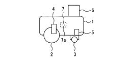
- FIG. 1 It is a side view of the autonomous moving body in Embodiment 1.
- FIG. 2 is a side view for demonstrating the operation of the autonomous moving body in Embodiment 1.
- FIG. 2 is a flowchart for demonstrating operation of the control device of an autonomous moving body in Embodiment 1.
- FIG. It is a hardware block diagram of the control device of the autonomous moving body in Embodiment 1.
- FIG. It is a side view of the autonomous moving body in Embodiment 2.
- FIG. It is a side view for demonstrating the operation of the autonomous moving body in Embodiment 2.
- FIG. It is a flowchart for demonstrating operation of the control device of an autonomous moving body in Embodiment 2.
- FIG. It is a side view of the autonomous moving body in Embodiment 3.
- FIG. 3 It is a side view for demonstrating the operation of the autonomous moving body in Embodiment 3.
- FIG. It is a figure which shows the vertical vibration of the main body of the autonomous moving body in Embodiment 3.
- FIG. It is a flowchart for demonstrating operation of the control device of an autonomous moving body in Embodiment 3.
- FIG. 1 is a side view of an autonomous moving body according to the first embodiment.
- the autonomous moving body includes a main body 1, a pair of drive wheels 2, a driven wheel 3, a drive side rotation detection device 4, a driven side rotation detection device 5, a camera 6, and a control device 7. Be prepared.
- the main body 1 forms the outer shell of the autonomous moving body.
- the main body 1 is formed in a rectangular parallelepiped.
- the pair of drive wheels 2 are rotatably provided on the rear side of the lower part of the main body 1.
- the pair of drive wheels 2 are provided so that a rotational driving force can be generated by a motor or the like (not shown).
- the driven wheel 3 is provided on the front side of the lower part of the main body 1.
- the driven wheel 3 is provided so as not to generate a driving force.
- the drive side rotation detection device 4 is provided on the rear side of the main body 1.
- the drive-side rotation detection device 4 is provided so as to be able to detect the rotation speed of at least one of the pair of drive wheels 2.
- the driven side rotation detection device 5 is provided on the front side of the main body 1.
- the driven side rotation detecting device 5 is provided so as to be able to detect the rotation speed of the driven wheel 3.
- the camera 6 is provided on the front side of the upper part of the main body 1.
- the camera 6 is provided so as to be able to photograph the front of the main body 1.
- the control device 7 is provided inside the main body 1.
- the control device 7 includes a control unit 7a.
- the control unit 7a is provided so as to be able to control the rotation of the drive wheel 2 based on the detection result of the drive side rotation detection device 4, the detection result of the driven side rotation detection device 5, and the shooting result of the camera 6.
- FIG. 2 is a side view for explaining the operation of the autonomous moving body in the first embodiment.
- the control device 7 rotates the pair of drive wheels 2 so that the speed VA of the main body 1 becomes a preset speed with the side of the driven wheels 3 as the front. After that, when the driven wheel 3 gets into step 8 of the passenger conveyor, a difference occurs between the speed of the driven wheel 3 and the speed of the pair of drive wheels 2.
- the control device 7 detects that the driven wheel 3 has entered step 8. In this case, the control device 7 controls a pair of drive wheels 2 in order to gradually stop the autonomous moving body. For example, the control device 7 starts decelerating the drive wheels 2. For example, the control device 7 rotates the drive wheels 2 in the opposite direction.
- control device 7 determines that the driven wheel 3 and the pair of drive wheels 2 have entered step 8 based on the change in the rotation speed or the torque of the pair of drive wheels 2.
- control device 7 rotates the pair of drive wheels 2 in the opposite directions so that the magnitude of the speed VA of the autonomous moving body matches the magnitude of the speed VB of the passenger conveyor.
- control device 7 speeds up or slows down the rotation speed of the pair of drive wheels 2 so that the position of the autonomous moving body becomes the preset position in step 8 based on the image of the camera 6. After that, when the position of the autonomous moving body becomes the preset position in step 8, the control device 7 stops the rotation of the pair of drive wheels 2.
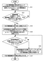
- FIG. 3 is a flowchart for explaining the operation of the control device of the autonomous moving body in the first embodiment.
- step S1 the control device 7 rotates the pair of drive wheels 2 so that the speed VA of the autonomous moving body becomes a preset speed with the side of the driven wheels 3 as the front. After that, the control device 7 performs the operation of step S2. In step S2, the control device 7 determines whether or not a preset difference has occurred between the speed of the driven wheel 3 and the speed of the pair of drive wheels 2.
- step S2 If the preset difference does not occur in step S2, the control device 7 performs the operation of step S2. When a preset difference occurs in step S2, the control device 7 performs the operation of step S3.
- step S3 the control device 7 controls a pair of drive wheels 2 in order to gradually stop the autonomous moving body. After that, the control device 7 performs the operation of step S4. In step S4, the control device 7 determines whether or not the driven wheel 3 and the pair of drive wheels 2 have boarded step 8.
- step S4 If the driven wheel 3 and the pair of drive wheels 2 do not get into step 8 in step S4, the control device 7 operates in step S4. When the driven wheel 3 and the pair of drive wheels 2 get into step 8 in step S4, the control device 7 operates in step S5.
- step S5 the control device 7 controls the rotation of the pair of drive wheels 2 so that the position of the autonomous moving body becomes the preset position in step 8. After that, the control device 7 performs the operation of step S6. In step S6, the control device 7 determines whether or not the position of the autonomous moving body is the preset position in step 8.
- step S6 If the position of the autonomous moving body is not the preset position in step 8 in step S6, the control device 7 performs the operation of step S5. When the position of the autonomous moving body is the preset position in step 8 in step S6, the control device 7 performs the operation of step S7.
- step S7 the control device 7 stops the rotation of the pair of drive wheels 2. After that, the control device 7 ends the operation.
- control device 7 indicates that the autonomous moving body has started to move to step 8 of the passenger conveyor based on the change in the rotation speed of the driven wheel 3 of the autonomous moving body. Detect. Therefore, the autonomous mobile body can be easily boarded in step 8 of the passenger conveyor.
- control device 7 decelerates the drive wheel 2 when it detects that the autonomous moving body has started to move to step 8 of the passenger conveyor based on the change in the rotation speed of the driven wheel 3. Therefore, the autonomous mobile body can be more easily boarded in step 8 of the passenger conveyor.
- control device 7 decelerates the drive wheels 2 when it detects that the autonomous moving body has started moving to step 8 of the passenger conveyor based on the change in the rotation speed of the driven wheels 3, and then decelerates the drive wheels 2. It is detected that the autonomous moving body has completely moved to step 8 of the passenger conveyor based on the change in the rotation speed or the change in the torque of the drive wheel 2. Therefore, it is possible to reliably detect that the autonomous mobile body has entered step 8.
- control device 7 detects that the autonomous moving body has started to move to step 8 of the passenger conveyor based on the change in the rotation speed of the driven wheel 3, the drive wheel 2 is decelerated, and then the drive wheel 2 is decelerated. It is detected that the autonomous moving body has completely moved to step 8 of the passenger conveyor based on the change in the rotation speed or the torque of the drive wheel 2, and then the moving direction of the autonomous moving body is the moving direction in step 8.
- the autonomous moving body is made to run in parallel in step 8. Therefore, it is possible to suppress the change in the absolute position of the autonomous moving body.
- FIG. 4 is a hardware configuration diagram of the control device for the autonomous mobile body according to the first embodiment.
- Each function of the control device 7 can be realized by a processing circuit.
- the processing circuit comprises at least one processor 100a and at least one memory 100b.
- the processing circuit comprises at least one dedicated hardware 200.
- each function of the control device 7 is realized by software, firmware, or a combination of software and firmware. At least one of the software and firmware is written as a program. At least one of the software and firmware is stored in at least one memory 100b. At least one processor 100a realizes each function of the control device 7 by reading and executing a program stored in at least one memory 100b. At least one processor 100a is also referred to as a central processing unit, a processing unit, an arithmetic unit, a microprocessor, a microcomputer, and a DSP.
- At least one memory 100b is a non-volatile or volatile semiconductor memory such as RAM, ROM, flash memory, EPROM, EEPROM, a magnetic disk, a flexible disk, an optical disk, a compact disk, a mini disk, a DVD, or the like.
- the processing circuit comprises at least one dedicated hardware 200
- the processing circuit may be implemented, for example, as a single circuit, a composite circuit, a programmed processor, a parallel programmed processor, an ASIC, an FPGA, or a combination thereof.
- each function of the control device 7 is realized by a processing circuit.
- each function of the control device 7 is collectively realized by a processing circuit.
- a part may be realized by the dedicated hardware 200, and the other part may be realized by software or firmware.
- the function of the control unit 7a is realized by a processing circuit as dedicated hardware 200, and for the functions other than the function of the control unit 7a, at least one processor 100a reads a program stored in at least one memory 100b. It may be realized by executing the above.
- the processing circuit realizes each function of the control device 7 by hardware 200, software, firmware, or a combination thereof.
- FIG. 5 is a side view of the autonomous moving body according to the second embodiment.
- the same or corresponding parts as those of the first embodiment are designated by the same reference numerals. The explanation of this part is omitted.
- the autonomous moving body includes a main body 1, a pair of drive wheels 2, a driven wheel 3, a drive side rotation detection device 4, a driven side rotation detection device 5, a camera 6, and a control device 7. Be prepared.
- the main body 1 forms the outer shell of the autonomous moving body.
- the main body 1 is formed in a rectangular parallelepiped.
- the pair of drive wheels 2 are rotatably provided on the front side of the lower part of the main body 1.
- the pair of drive wheels 2 are provided so that a rotational driving force can be generated by a motor or the like (not shown).
- the driven wheel 3 is provided on the rear side of the lower part of the main body 1.
- the driven wheel 3 is provided so as not to generate a driving force.
- the drive side rotation detection device 4 is provided on the front side of the main body 1.
- the drive-side rotation detection device 4 is provided so as to be able to detect the rotation speed of at least one of the pair of drive wheels 2.
- the driven side rotation detection device 5 is provided on the rear side of the main body 1.
- the driven side rotation detecting device 5 is provided so as to be able to detect the rotation speed of the driven wheel 3.
- the camera 6 is provided on the front side of the upper part of the main body 1.
- the camera 6 is provided so as to be able to photograph the front of the main body 1.
- the control device 7 is provided inside the main body 1.
- the control device 7 includes a control unit 7a.
- the control unit 7a is provided so as to be able to control the rotation of the drive wheel 2 based on the detection result of the drive side rotation detection device 4, the detection result of the driven side rotation detection device 5, and the shooting result of the camera 6.
- FIG. 6 is a side view for explaining the operation of the autonomous moving body in the second embodiment.
- the control device 7 rotates the pair of drive wheels 2 so that the speed VA of the autonomous moving body becomes a preset speed with the side of the pair of drive wheels 2 as the front. After that, when the pair of drive wheels 2 get into step 8 of the passenger conveyor, a difference occurs between the speed of the driven wheels 3 and the speed of the pair of drive wheels 2.
- control device 7 detects that the pair of drive wheels 2 has entered step 8. In this case, the control device 7 rotates the pair of drive wheels 2 in the opposite directions. After that, the control device 7 rotates the pair of drive wheels 2 in the opposite directions so that the magnitude of the speed VA of the autonomous moving body matches the magnitude of the speed VB of the passenger conveyor.
- control device 7 speeds up or slows down the rotation speed of the pair of drive wheels 2 so that the position of the main body 1 becomes the preset position in step 8 based on the image of the camera 6. After that, when the position of the main body 1 becomes the preset position in step 8, the control device 7 stops the rotation of the pair of drive wheels 2.
- FIG. 7 is a flowchart for explaining the operation of the control device of the autonomous moving body in the second embodiment.
- step S11 the control device 7 rotates the pair of drive wheels 2 so that the speed VA of the autonomous moving body becomes a preset speed with the side of the pair of drive wheels 2 as the front. After that, the control device 7 performs the operation of step S12. In step S12, the control device 7 determines whether or not a preset difference has occurred between the speed of the driven wheel 3 and the speed of the pair of drive wheels 2.
- step S12 If the preset difference does not occur in step S12, the control device 7 operates in step S12. When a preset difference occurs in step S12, the control device 7 performs the operation of step S13.
- step S13 the control device 7 rotates the pair of drive wheels 2 in the opposite direction. After that, the control device 7 performs the operation of step S14.
- step S14 the control device 7 rotates the pair of drive wheels 2 in the opposite directions so that the magnitude of the velocity VA of the autonomous moving body matches the magnitude of the velocity VB of the passenger conveyor.
- step S15 the control device 7 determines whether or not the position of the autonomous moving body is the preset position in step 8.
- step S15 the control device 7 operates in step S16.
- step S16 the control device 7 controls the rotation of the pair of drive wheels 2 so that the position of the autonomous moving body becomes the preset position in step 8. After that, the control device 7 performs the operation of step S15.
- step S15 When the position of the autonomous moving body is the preset position in step 8 in step S15, the control device 7 performs the operation of step S17.
- step S17 the control device 7 stops the rotation of the pair of drive wheels 2. After that, the control device 7 ends the operation.
- the control device 7 when the control device 7 detects the start of movement to the step 8 based on the change in the rotation speed of the drive wheels 2, the control device 7 rotates the drive wheels 2 in the opposite direction. .. Therefore, the autonomous mobile body can be easily boarded in step 8 of the passenger conveyor.
- control device 7 detects the start of movement to step 8 based on the change in the rotation speed of the drive wheels 2, and then the moving direction of the autonomous moving body becomes opposite to the moving direction of step 8 and is autonomous.
- the autonomous moving body is made to run in parallel in step 8. Therefore, it is possible to suppress the change in the absolute position of the autonomous moving body.
- control device 7 stops the drive wheel 2 when the position of the autonomous moving body reaches the preset position in step 8 when the autonomous moving body is running in parallel in step 8. Therefore, the autonomous moving body can be stopped at an appropriate position in step 8.
- FIG. 8 is a side view of the autonomous moving body according to the third embodiment.
- the same or corresponding parts as those of the first embodiment are designated by the same reference numerals. The explanation of this part is omitted.
- the autonomous moving body includes a main body 1, a pair of drive wheels 2, a driven wheel 3, a drive side rotation detection device 4, a driven side rotation detection device 5, a camera 6, and an acceleration detection device 9.
- a control device 7 is provided.
- the main body 1 forms the outer shell of the autonomous moving body.
- the main body 1 is formed in a rectangular parallelepiped.
- the pair of drive wheels 2 are rotatably provided on the front side of the lower part of the main body 1.
- the pair of drive wheels 2 are provided so that a rotational driving force can be generated by a motor or the like (not shown).
- the driven wheel 3 is provided on the rear side of the lower part of the main body 1.
- the driven wheel 3 is provided so as not to generate a driving force.
- the drive side rotation detection device 4 is provided on the front side of the main body 1.
- the drive-side rotation detection device 4 is provided so as to be able to detect the rotation speed of at least one of the pair of drive wheels 2.
- the driven side rotation detection device 5 is provided on the rear side of the main body 1.
- the driven side rotation detecting device 5 is provided so as to be able to detect the rotation speed of the driven wheel 3.
- the camera 6 is provided on the front side of the upper part of the main body 1.
- the camera 6 is provided so as to be able to photograph the front of the main body 1.
- the acceleration detection device 9 is provided inside the main body 1.
- the acceleration detection device 9 is provided so as to be able to detect the acceleration of the main body 1.
- the control device 7 is provided inside the main body 1.
- the control device 7 is provided so as to be able to control the rotation of the drive wheel 2 based on the detection result of the drive side rotation detection device 4, the detection result of the driven side rotation detection device 5, and the shooting result of the camera 6.
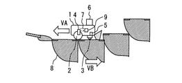
- FIG. 9 is a side view for explaining the operation of the autonomous moving body in the third embodiment.
- the control device 7 rotates the pair of drive wheels 2 so that the speed VA of the main body 1 becomes a preset speed with the side of the driven wheels 3 as the front. After that, when the driven wheel 3 gets into step 8 of the passenger conveyor, a difference occurs between the speed of the driven wheel 3 and the speed of the pair of drive wheels 2.
- the control device 7 detects that the driven wheel 3 has entered step 8.
- the control device 7 controls a pair of drive wheels 2 in order to gradually stop the autonomous moving body.
- the control device 7 starts decelerating the drive wheels 2.
- the control device 7 rotates the pair of drive wheels 2 in opposite directions.
- control device 7 determines that the driven wheel 3 and the pair of drive wheels 2 have entered step 8 based on the change in the rotation speed or the torque of the pair of drive wheels 2.
- control device 7 rotates the pair of drive wheels 2 in the opposite directions so that the size of the speed VA of the main body 1 matches the size of the speed VB of the passenger conveyor.
- the control device 7 sets the pair of drive wheels. Stop the rotation of 2.
- FIG. 10 is a diagram showing vertical vibration of the main body of the autonomous moving body in the third embodiment.
- FIG. 10 shows a vibration pattern when the driven wheel 3 is on step 8 of the passenger conveyor.
- the driven wheel 3 is temporarily and periodically impacted.
- the vibration of the main body 1 becomes large temporarily and periodically.
- FIG. 11 is a flowchart for explaining the operation of the control device of the autonomous moving body in the third embodiment.
- step S21 the control device 7 rotates the pair of drive wheels 2 so that the speed VA of the autonomous moving body becomes a preset speed with the side of the driven wheels 3 as the front. After that, the control device 7 performs the operation of step S22. In step S22, the control device 7 determines whether or not a preset difference has occurred between the speed of the driven wheel 3 and the speed of the pair of drive wheels 2.
- step S22 If the preset difference does not occur in step S22, the control device 7 operates in step S22. When a preset difference occurs in step S22, the control device 7 performs the operation of step S23.
- step S23 the control device 7 controls a pair of drive wheels 2 in order to gradually stop the autonomous moving body. After that, the control device 7 performs the operation of step S24. In step S24, the control device 7 determines whether or not the driven wheel 3 and the pair of drive wheels 2 have boarded step 8.
- step S24 If the driven wheel 3 and the pair of drive wheels 2 do not get into step 8 in step S24, the control device 7 operates in step S24. When the driven wheel 3 and the pair of drive wheels 2 get into step 8 in step S24, the control device 7 operates in step S25.
- step S25 the control device 7 controls the rotation of the pair of drive wheels 2 so that the position of the autonomous moving body becomes the preset position in step 8. After that, the control device 7 performs the operation of step S26. In step S26, the control device 7 determines whether or not the position of the autonomous moving body is the preset position in step 8.
- step S26 If the position of the autonomous moving body is not the preset position in step 8 in step S26, the control device 7 operates in step S25. When the position of the autonomous moving body is the preset position in step 8 in step S26, the control device 7 performs the operation of step S27.
- step S27 the control device 7 stops the rotation of the pair of drive wheels 2. After that, the control device 7 ends the operation.
- the vibration pattern of the autonomous moving body becomes a preset pattern.
- the drive wheel 2 is stopped. Therefore, the autonomous moving body can be stopped accurately at the appropriate position in step 8.
- control device and the autonomous mobile body of the autonomous mobile body of the present disclosure can be used in the system for getting the autonomous mobile body onto the passenger conveyor.
Landscapes
- Engineering & Computer Science (AREA)
- Aviation & Aerospace Engineering (AREA)
- Radar, Positioning & Navigation (AREA)
- Remote Sensing (AREA)
- Physics & Mathematics (AREA)
- General Physics & Mathematics (AREA)
- Automation & Control Theory (AREA)
- Control Of Position, Course, Altitude, Or Attitude Of Moving Bodies (AREA)
- Escalators And Moving Walkways (AREA)
Priority Applications (3)
| Application Number | Priority Date | Filing Date | Title |
|---|---|---|---|
| CN202080104386.4A CN116018571B (zh) | 2020-08-06 | 2020-08-06 | 自主移动体的控制装置以及自主移动体 |
| PCT/JP2020/030249 WO2022029970A1 (ja) | 2020-08-06 | 2020-08-06 | 自律移動体の制御装置および自律移動体 |
| JP2022541055A JP7334863B2 (ja) | 2020-08-06 | 2020-08-06 | 自律移動体の制御装置および自律移動体 |
Applications Claiming Priority (1)
| Application Number | Priority Date | Filing Date | Title |
|---|---|---|---|
| PCT/JP2020/030249 WO2022029970A1 (ja) | 2020-08-06 | 2020-08-06 | 自律移動体の制御装置および自律移動体 |
Publications (1)
| Publication Number | Publication Date |
|---|---|
| WO2022029970A1 true WO2022029970A1 (ja) | 2022-02-10 |
Family
ID=80117784
Family Applications (1)
| Application Number | Title | Priority Date | Filing Date |
|---|---|---|---|
| PCT/JP2020/030249 Ceased WO2022029970A1 (ja) | 2020-08-06 | 2020-08-06 | 自律移動体の制御装置および自律移動体 |
Country Status (3)
| Country | Link |
|---|---|
| JP (1) | JP7334863B2 (https=) |
| CN (1) | CN116018571B (https=) |
| WO (1) | WO2022029970A1 (https=) |
Citations (2)
| Publication number | Priority date | Publication date | Assignee | Title |
|---|---|---|---|---|
| JPH0580840A (ja) * | 1991-09-19 | 1993-04-02 | Kubota Corp | 作業車の走行制御装置 |
| US20200047627A1 (en) * | 2019-09-19 | 2020-02-13 | Lg Electronics Inc. | Robot system and control method of the same |
Family Cites Families (6)
| Publication number | Priority date | Publication date | Assignee | Title |
|---|---|---|---|---|
| JPH10167649A (ja) * | 1996-12-03 | 1998-06-23 | Sanwa:Kk | 車いす運搬車用のエスカレータ制御システム |
| JPH10314235A (ja) * | 1997-05-20 | 1998-12-02 | Exedy Corp | 走行車輌 |
| JP6571631B2 (ja) * | 2016-12-26 | 2019-09-04 | 国立大学法人 東京大学 | 走行車両及び走行車両の制御方法 |
| JP7279331B2 (ja) * | 2018-10-05 | 2023-05-23 | 三菱電機ビルソリューションズ株式会社 | 利用者に適した運転を実施するエスカレーターシステム |
| CN110654965B (zh) * | 2019-09-26 | 2021-01-15 | 京东方科技集团股份有限公司 | 搬运系统及其控制方法 |
| CN110902544B (zh) * | 2019-12-11 | 2024-07-26 | 广州广日电梯工业有限公司 | 一种购物车专用扶梯系统 |
-
2020
- 2020-08-06 CN CN202080104386.4A patent/CN116018571B/zh active Active
- 2020-08-06 WO PCT/JP2020/030249 patent/WO2022029970A1/ja not_active Ceased
- 2020-08-06 JP JP2022541055A patent/JP7334863B2/ja active Active
Patent Citations (2)
| Publication number | Priority date | Publication date | Assignee | Title |
|---|---|---|---|---|
| JPH0580840A (ja) * | 1991-09-19 | 1993-04-02 | Kubota Corp | 作業車の走行制御装置 |
| US20200047627A1 (en) * | 2019-09-19 | 2020-02-13 | Lg Electronics Inc. | Robot system and control method of the same |
Also Published As
| Publication number | Publication date |
|---|---|
| JP7334863B2 (ja) | 2023-08-29 |
| CN116018571B (zh) | 2024-09-17 |
| JPWO2022029970A1 (https=) | 2022-02-10 |
| CN116018571A (zh) | 2023-04-25 |
Similar Documents
| Publication | Publication Date | Title |
|---|---|---|
| CN108082185B (zh) | 一种车辆的行驶控制方法、装置和车辆 | |
| WO2022029971A1 (ja) | 自律移動体の制御装置および自律移動体 | |
| JP6070669B2 (ja) | エンジン停止装置 | |
| WO2022029970A1 (ja) | 自律移動体の制御装置および自律移動体 | |
| WO2016157369A1 (ja) | エレベータの制御システム | |
| JP4515369B2 (ja) | 建設機械の駆動制御装置 | |
| JP5361691B2 (ja) | 自動二輪車のバンク角推定装置及び方法 | |
| JP2018170871A (ja) | 全方向移動車両 | |
| CN109415051B (zh) | 用于在单辙的机动车中减缓侧向摆动运动的方法和装置 | |
| US20180162291A1 (en) | System and method of dynamically adjusting field of view of an image capturing device | |
| JP2004085838A5 (https=) | ||
| EP1669829A3 (en) | Controller with means for determining acceleration | |
| JP6354944B2 (ja) | ミラー制御装置 | |
| JP2009201321A (ja) | 倒立車輪式移動ロボットとその制御方法 | |
| WO2017158956A1 (ja) | 独立車輪駆動制御装置 | |
| JPH0912266A (ja) | 天井クレーンの走行制御装置 | |
| JP6595828B2 (ja) | 撮像装置、及び撮像装置の制御方法 | |
| JP7608270B2 (ja) | 車両状態特定装置並びに同方法、車両用灯具の光軸制御装置並びに同方法、車両用灯具システム | |
| JP2020104791A (ja) | 制御装置および制御方法 | |
| JP5361692B2 (ja) | 自動二輪車のバンク角推定装置及び方法 | |
| JP6576722B2 (ja) | 撮像装置 | |
| JP2013049425A5 (https=) | ||
| JP3674730B2 (ja) | モータの制御装置 | |
| JPH10207548A (ja) | 無人搬送車の制御装置 | |
| JP2023046009A (ja) | 搬送車 |
Legal Events
| Date | Code | Title | Description |
|---|---|---|---|
| 121 | Ep: the epo has been informed by wipo that ep was designated in this application |
Ref document number: 20947972 Country of ref document: EP Kind code of ref document: A1 |
|
| ENP | Entry into the national phase |
Ref document number: 2022541055 Country of ref document: JP Kind code of ref document: A |
|
| NENP | Non-entry into the national phase |
Ref country code: DE |
|
| 122 | Ep: pct application non-entry in european phase |
Ref document number: 20947972 Country of ref document: EP Kind code of ref document: A1 |