WO2022029861A1 - 塗布装置及び塗布方法 - Google Patents
塗布装置及び塗布方法 Download PDFInfo
- Publication number
- WO2022029861A1 WO2022029861A1 PCT/JP2020/029742 JP2020029742W WO2022029861A1 WO 2022029861 A1 WO2022029861 A1 WO 2022029861A1 JP 2020029742 W JP2020029742 W JP 2020029742W WO 2022029861 A1 WO2022029861 A1 WO 2022029861A1
- Authority
- WO
- WIPO (PCT)
- Prior art keywords
- nozzle
- liquid
- coating
- discharge port
- height
- Prior art date
- Legal status (The legal status is an assumption and is not a legal conclusion. Google has not performed a legal analysis and makes no representation as to the accuracy of the status listed.)
- Ceased
Links
Images




Classifications
-
- B—PERFORMING OPERATIONS; TRANSPORTING
- B05—SPRAYING OR ATOMISING IN GENERAL; APPLYING FLUENT MATERIALS TO SURFACES, IN GENERAL
- B05C—APPARATUS FOR APPLYING FLUENT MATERIALS TO SURFACES, IN GENERAL
- B05C9/00—Apparatus or plant for applying liquid or other fluent material to surfaces by means not covered by any preceding group, or in which the means of applying the liquid or other fluent material is not important
- B05C9/06—Apparatus or plant for applying liquid or other fluent material to surfaces by means not covered by any preceding group, or in which the means of applying the liquid or other fluent material is not important for applying two different liquids or other fluent materials, or the same liquid or other fluent material twice, to the same side of the work
-
- B—PERFORMING OPERATIONS; TRANSPORTING
- B05—SPRAYING OR ATOMISING IN GENERAL; APPLYING FLUENT MATERIALS TO SURFACES, IN GENERAL
- B05C—APPARATUS FOR APPLYING FLUENT MATERIALS TO SURFACES, IN GENERAL
- B05C1/00—Apparatus in which liquid or other fluent material is applied to the surface of the work by contact with a member carrying the liquid or other fluent material, e.g. a porous member loaded with a liquid to be applied as a coating
- B05C1/04—Apparatus in which liquid or other fluent material is applied to the surface of the work by contact with a member carrying the liquid or other fluent material, e.g. a porous member loaded with a liquid to be applied as a coating for applying liquid or other fluent material to work of indefinite length
- B05C1/08—Apparatus in which liquid or other fluent material is applied to the surface of the work by contact with a member carrying the liquid or other fluent material, e.g. a porous member loaded with a liquid to be applied as a coating for applying liquid or other fluent material to work of indefinite length using a roller or other rotating member which contacts the work along a generating line
- B05C1/0813—Apparatus in which liquid or other fluent material is applied to the surface of the work by contact with a member carrying the liquid or other fluent material, e.g. a porous member loaded with a liquid to be applied as a coating for applying liquid or other fluent material to work of indefinite length using a roller or other rotating member which contacts the work along a generating line characterised by means for supplying liquid or other fluent material to the roller
-
- B—PERFORMING OPERATIONS; TRANSPORTING
- B05—SPRAYING OR ATOMISING IN GENERAL; APPLYING FLUENT MATERIALS TO SURFACES, IN GENERAL
- B05B—SPRAYING APPARATUS; ATOMISING APPARATUS; NOZZLES
- B05B7/00—Spraying apparatus for discharge of liquids or other fluent materials from two or more sources, e.g. of liquid and air, of powder and gas
- B05B7/24—Spraying apparatus for discharge of liquids or other fluent materials from two or more sources, e.g. of liquid and air, of powder and gas with means, e.g. a container, for supplying liquid or other fluent material to a discharge device
- B05B7/2489—Spraying apparatus for discharge of liquids or other fluent materials from two or more sources, e.g. of liquid and air, of powder and gas with means, e.g. a container, for supplying liquid or other fluent material to a discharge device an atomising fluid, e.g. a gas, being supplied to the discharge device
- B05B7/2491—Spraying apparatus for discharge of liquids or other fluent materials from two or more sources, e.g. of liquid and air, of powder and gas with means, e.g. a container, for supplying liquid or other fluent material to a discharge device an atomising fluid, e.g. a gas, being supplied to the discharge device characterised by the means for producing or supplying the atomising fluid, e.g. air hoses, air pumps, gas containers, compressors, fans, ventilators, their drives
-
- B—PERFORMING OPERATIONS; TRANSPORTING
- B05—SPRAYING OR ATOMISING IN GENERAL; APPLYING FLUENT MATERIALS TO SURFACES, IN GENERAL
- B05C—APPARATUS FOR APPLYING FLUENT MATERIALS TO SURFACES, IN GENERAL
- B05C1/00—Apparatus in which liquid or other fluent material is applied to the surface of the work by contact with a member carrying the liquid or other fluent material, e.g. a porous member loaded with a liquid to be applied as a coating
- B05C1/04—Apparatus in which liquid or other fluent material is applied to the surface of the work by contact with a member carrying the liquid or other fluent material, e.g. a porous member loaded with a liquid to be applied as a coating for applying liquid or other fluent material to work of indefinite length
-
- B—PERFORMING OPERATIONS; TRANSPORTING
- B05—SPRAYING OR ATOMISING IN GENERAL; APPLYING FLUENT MATERIALS TO SURFACES, IN GENERAL
- B05C—APPARATUS FOR APPLYING FLUENT MATERIALS TO SURFACES, IN GENERAL
- B05C1/00—Apparatus in which liquid or other fluent material is applied to the surface of the work by contact with a member carrying the liquid or other fluent material, e.g. a porous member loaded with a liquid to be applied as a coating
- B05C1/04—Apparatus in which liquid or other fluent material is applied to the surface of the work by contact with a member carrying the liquid or other fluent material, e.g. a porous member loaded with a liquid to be applied as a coating for applying liquid or other fluent material to work of indefinite length
- B05C1/08—Apparatus in which liquid or other fluent material is applied to the surface of the work by contact with a member carrying the liquid or other fluent material, e.g. a porous member loaded with a liquid to be applied as a coating for applying liquid or other fluent material to work of indefinite length using a roller or other rotating member which contacts the work along a generating line
- B05C1/0804—Apparatus in which liquid or other fluent material is applied to the surface of the work by contact with a member carrying the liquid or other fluent material, e.g. a porous member loaded with a liquid to be applied as a coating for applying liquid or other fluent material to work of indefinite length using a roller or other rotating member which contacts the work along a generating line the material being applied without contact with the roller
-
- B—PERFORMING OPERATIONS; TRANSPORTING
- B05—SPRAYING OR ATOMISING IN GENERAL; APPLYING FLUENT MATERIALS TO SURFACES, IN GENERAL
- B05C—APPARATUS FOR APPLYING FLUENT MATERIALS TO SURFACES, IN GENERAL
- B05C1/00—Apparatus in which liquid or other fluent material is applied to the surface of the work by contact with a member carrying the liquid or other fluent material, e.g. a porous member loaded with a liquid to be applied as a coating
- B05C1/04—Apparatus in which liquid or other fluent material is applied to the surface of the work by contact with a member carrying the liquid or other fluent material, e.g. a porous member loaded with a liquid to be applied as a coating for applying liquid or other fluent material to work of indefinite length
- B05C1/08—Apparatus in which liquid or other fluent material is applied to the surface of the work by contact with a member carrying the liquid or other fluent material, e.g. a porous member loaded with a liquid to be applied as a coating for applying liquid or other fluent material to work of indefinite length using a roller or other rotating member which contacts the work along a generating line
- B05C1/0826—Apparatus in which liquid or other fluent material is applied to the surface of the work by contact with a member carrying the liquid or other fluent material, e.g. a porous member loaded with a liquid to be applied as a coating for applying liquid or other fluent material to work of indefinite length using a roller or other rotating member which contacts the work along a generating line the work being a web or sheets
- B05C1/083—Apparatus in which liquid or other fluent material is applied to the surface of the work by contact with a member carrying the liquid or other fluent material, e.g. a porous member loaded with a liquid to be applied as a coating for applying liquid or other fluent material to work of indefinite length using a roller or other rotating member which contacts the work along a generating line the work being a web or sheets being passed between the coating roller and one or more backing rollers
-
- B—PERFORMING OPERATIONS; TRANSPORTING
- B05—SPRAYING OR ATOMISING IN GENERAL; APPLYING FLUENT MATERIALS TO SURFACES, IN GENERAL
- B05C—APPARATUS FOR APPLYING FLUENT MATERIALS TO SURFACES, IN GENERAL
- B05C11/00—Component parts, details or accessories not specifically provided for in groups B05C1/00 - B05C9/00
- B05C11/02—Apparatus for spreading or distributing liquids or other fluent materials already applied to a surface ; Controlling means therefor; Control of the thickness of a coating by spreading or distributing liquids or other fluent materials already applied to the coated surface
- B05C11/04—Apparatus for spreading or distributing liquids or other fluent materials already applied to a surface ; Controlling means therefor; Control of the thickness of a coating by spreading or distributing liquids or other fluent materials already applied to the coated surface with blades
-
- B—PERFORMING OPERATIONS; TRANSPORTING
- B05—SPRAYING OR ATOMISING IN GENERAL; APPLYING FLUENT MATERIALS TO SURFACES, IN GENERAL
- B05C—APPARATUS FOR APPLYING FLUENT MATERIALS TO SURFACES, IN GENERAL
- B05C11/00—Component parts, details or accessories not specifically provided for in groups B05C1/00 - B05C9/00
- B05C11/10—Storage, supply or control of liquid or other fluent material; Recovery of excess liquid or other fluent material
- B05C11/1044—Apparatus or installations for supplying liquid or other fluent material to several applying apparatus or several dispensing outlets, e.g. to several extrusion nozzles
-
- B—PERFORMING OPERATIONS; TRANSPORTING
- B05—SPRAYING OR ATOMISING IN GENERAL; APPLYING FLUENT MATERIALS TO SURFACES, IN GENERAL
- B05C—APPARATUS FOR APPLYING FLUENT MATERIALS TO SURFACES, IN GENERAL
- B05C3/00—Apparatus in which the work is brought into contact with a bulk quantity of liquid or other fluent material
- B05C3/18—Apparatus in which the work is brought into contact with a bulk quantity of liquid or other fluent material only one side of the work coming into contact with the liquid or other fluent material
-
- B—PERFORMING OPERATIONS; TRANSPORTING
- B05—SPRAYING OR ATOMISING IN GENERAL; APPLYING FLUENT MATERIALS TO SURFACES, IN GENERAL
- B05C—APPARATUS FOR APPLYING FLUENT MATERIALS TO SURFACES, IN GENERAL
- B05C5/00—Apparatus in which liquid or other fluent material is projected, poured or allowed to flow on to the surface of the work
- B05C5/02—Apparatus in which liquid or other fluent material is projected, poured or allowed to flow on to the surface of the work the liquid or other fluent material being discharged through an outlet orifice by pressure, e.g. from an outlet device in contact or almost in contact, with the work
- B05C5/027—Coating heads with several outlets, e.g. aligned transversally to the moving direction of a web to be coated
-
- B—PERFORMING OPERATIONS; TRANSPORTING
- B05—SPRAYING OR ATOMISING IN GENERAL; APPLYING FLUENT MATERIALS TO SURFACES, IN GENERAL
- B05C—APPARATUS FOR APPLYING FLUENT MATERIALS TO SURFACES, IN GENERAL
- B05C9/00—Apparatus or plant for applying liquid or other fluent material to surfaces by means not covered by any preceding group, or in which the means of applying the liquid or other fluent material is not important
- B05C9/02—Apparatus or plant for applying liquid or other fluent material to surfaces by means not covered by any preceding group, or in which the means of applying the liquid or other fluent material is not important for applying liquid or other fluent material to surfaces by single means not covered by groups B05C1/00 - B05C7/00, whether or not also using other means
-
- B—PERFORMING OPERATIONS; TRANSPORTING
- B05—SPRAYING OR ATOMISING IN GENERAL; APPLYING FLUENT MATERIALS TO SURFACES, IN GENERAL
- B05C—APPARATUS FOR APPLYING FLUENT MATERIALS TO SURFACES, IN GENERAL
- B05C9/00—Apparatus or plant for applying liquid or other fluent material to surfaces by means not covered by any preceding group, or in which the means of applying the liquid or other fluent material is not important
- B05C9/08—Apparatus or plant for applying liquid or other fluent material to surfaces by means not covered by any preceding group, or in which the means of applying the liquid or other fluent material is not important for applying liquid or other fluent material and performing an auxiliary operation
- B05C9/14—Apparatus or plant for applying liquid or other fluent material to surfaces by means not covered by any preceding group, or in which the means of applying the liquid or other fluent material is not important for applying liquid or other fluent material and performing an auxiliary operation the auxiliary operation involving heating or cooling
-
- B—PERFORMING OPERATIONS; TRANSPORTING
- B05—SPRAYING OR ATOMISING IN GENERAL; APPLYING FLUENT MATERIALS TO SURFACES, IN GENERAL
- B05D—PROCESSES FOR APPLYING FLUENT MATERIALS TO SURFACES, IN GENERAL
- B05D1/00—Processes for applying liquids or other fluent materials
- B05D1/26—Processes for applying liquids or other fluent materials performed by applying the liquid or other fluent material from an outlet device in contact with, or almost in contact with, the surface
-
- B—PERFORMING OPERATIONS; TRANSPORTING
- B05—SPRAYING OR ATOMISING IN GENERAL; APPLYING FLUENT MATERIALS TO SURFACES, IN GENERAL
- B05D—PROCESSES FOR APPLYING FLUENT MATERIALS TO SURFACES, IN GENERAL
- B05D1/00—Processes for applying liquids or other fluent materials
- B05D1/28—Processes for applying liquids or other fluent materials performed by transfer from the surfaces of elements carrying the liquid or other fluent material, e.g. brushes, pads, rollers
-
- B—PERFORMING OPERATIONS; TRANSPORTING
- B05—SPRAYING OR ATOMISING IN GENERAL; APPLYING FLUENT MATERIALS TO SURFACES, IN GENERAL
- B05D—PROCESSES FOR APPLYING FLUENT MATERIALS TO SURFACES, IN GENERAL
- B05D2252/00—Sheets
- B05D2252/02—Sheets of indefinite length
Definitions
- the embodiment of the present invention relates to a coating device and a coating method.
- a coating head that applies the liquid using the coating bar.
- a coating device capable of forming a uniform coating film is desired.
- An embodiment of the present invention provides a coating device and a coating method capable of forming a uniform coating film.
- the coating device includes a first tube, a first pump, a first nozzle, a second nozzle and a holding portion.
- the first pipe includes the first inlet, the first outlet and the second outlet.
- the first pump can supply a liquid toward the first inflow port.
- the first nozzle includes the first nozzle inlet and the first nozzle outlet.
- the first nozzle inlet is connected to the first outlet.
- the first nozzle discharge port can discharge the liquid that has passed through the first pipe.
- the second nozzle includes the second nozzle inlet and the second nozzle outlet.
- the second nozzle inlet is connected to the second outlet.
- the second nozzle discharge port can discharge the liquid that has passed through the first pipe.
- the holding portion holds the first nozzle and the second nozzle.
- the holding portion can form a first state and a second state.
- the first state the height of the first nozzle discharge port and the height of the second nozzle discharge port are equal to or higher than the height of the first pipe.
- the second state the height of the first nozzle discharge port and the height of the second nozzle discharge port are lower than the height of the first pipe.
- FIG. 1 is a schematic side view illustrating the coating device according to the first embodiment.
- FIG. 2 is a schematic top view illustrating the coating device according to the first embodiment.
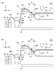
- 3A and 3B are schematic side views illustrating the coating apparatus according to the first embodiment.
- 4 (a) and 4 (b) are schematic side views illustrating the coating apparatus according to the first embodiment.
- 5 (a) and 5 (b) are schematic side views illustrating the coating apparatus according to the first embodiment.
- 6 (a) and 6 (b) are schematic side views illustrating the coating apparatus according to the first embodiment.
- 7 (a) and 7 (b) are schematic side views illustrating the coating apparatus according to the first embodiment.
- 8 (a) and 8 (b) are schematic side views illustrating the coating apparatus according to the first embodiment.
- FIG. 9 is a schematic side view illustrating a part of the coating device according to the first embodiment.
- FIG. 10 is a flowchart illustrating the coating method according to the second embodiment.
- FIG. 1 is a schematic side view illustrating the coating device according to the first embodiment.
- FIG. 2 is a schematic top view illustrating the coating device according to the first embodiment.
- 3 (a), 3 (b), 4 (a), 4 (b), 5 (a) and 5 (b) are schematics illustrating the coating apparatus according to the first embodiment. It is a side view.
- the coating device 110 according to the embodiment includes a first pipe 21, a first pump 31, a first nozzle 11, a second nozzle 12, and a holding portion 41.
- the first pipe 21 includes a first inlet 21i, a first outlet 21a, and a second outlet 21b.
- the first pump 31 can supply the liquid 50 toward the first inflow port 21i.
- the liquid 50 is stored in the container 55.
- the liquid 50 flows into the first pump 31 via the pipe 28a.
- the first nozzle 11 includes a first nozzle inlet 11i and a first nozzle outlet 11o.
- the first nozzle inlet 11i is connected to the first outlet 21a.
- the first nozzle discharge port 11o can discharge the liquid 50 that has passed through the first pipe 21.
- the first pump 31 supplies the liquid 50 to the first pipe 21, the liquid 50 is discharged from the first nozzle discharge port 11o.
- the second nozzle 12 includes a second nozzle inlet 12i and a second nozzle outlet 12o.
- the second nozzle inlet 12i is connected to the second outlet 21b.
- the second nozzle discharge port 12o can discharge the liquid 50 that has passed through the first pipe 21.
- the first pump 31 supplies the liquid 50 to the first pipe 21, the liquid 50 is discharged from the second nozzle discharge port 12o.
- the holding unit 41 holds the first nozzle 11 and the second nozzle 12.
- the holding portion 41 has a bar shape.
- the first nozzle 11 and the second nozzle 12 may be fixed to the holding portion 41 by any method.
- a substrate 48 is provided.
- the surface of the substrate 48 extends, for example, along the XY plane.
- the direction perpendicular to the XY plane is the Z-axis direction.
- the holding portion base 41B is provided on the base 48.
- the holding portion base 41B may be movable with respect to the base 48.
- the holding portion base 41B holds the bar-shaped holding portion 41.
- the bar-shaped holding portion 41 extends, for example, along the Y-axis direction.
- the holding portion 41 is rotatable with respect to the holding portion base 41B.
- the rotation is, for example, centered in the Y-axis direction.
- the angle of the holding portion 41 can be changed with reference to the holding portion base 41B.
- the angle may be changeable while the angle is limited.
- the angles of the plurality of nozzles held by the holding portion 41 also change.
- the angles of the plurality of nozzles may change without changing the angles of the holding portion 41.
- the holding unit 41 has a plurality of states.
- the holding portion 41 can form a plurality of states (for example, a first state and a second state).
- 3 (a) and 3 (b) illustrate the first state ST1.
- 4 (a) and 4 (b) illustrate the second state ST2.
- FIGS. 3 (a) and 4 (a) illustrate a portion including the first nozzle 11.
- 3 (b) and 4 (b) illustrate the portion including the second nozzle 12.
- some elements included in the coating device 110 are omitted for the sake of clarity.
- the height of the first nozzle discharge port 11o and the height of the second nozzle discharge port 12o are the heights of the first pipe 21. That is all.
- the height of the first nozzle discharge port 11o and the height of the second nozzle discharge port 12o are higher than the height of the first pipe 21. Is also low.
- the height is, for example, a position in the Z-axis direction.
- the height is, for example, a position in the Z-axis direction with respect to the substrate 48.
- the liquid 50 may be supplied to the first pipe 21 in a state where a gas such as air remains inside a part of the first pipe 21.
- gas such as air may remain in at least one of the first nozzle 11 and the second nozzle 12.
- the state in which the gas is not discharged and the liquid is easily discharged from the nozzle in which no gas remains is likely to continue. If the gas is not discharged, it becomes difficult to uniformly discharge the liquid 50. If the liquid 50 is not uniformly discharged, the liquid 50 tends to be unevenly applied to the member to be coated 81.
- the above-mentioned first state ST1 and second state ST2 can be formed.
- the first pump 31 can supply the liquid 50 to the first inflow port 21i in the first state ST1 and discharge the liquid 50 from the first nozzle discharge port 11o and the second nozzle discharge port 12o. ..
- the height of the first nozzle discharge port 11o and the height of the second nozzle discharge port 12o are equal to or higher than the height of the first pipe 21.
- gas is supplied to the first pipe 21, the first nozzle 12, and the second nozzle 12. Gas can also be expelled from these nozzles if is present. This enables uniform discharge.
- the liquid 50 is discharged from the first nozzle 11 and the second nozzle 12, and the liquid 50 is applied to the member to be coated 81.
- the applied liquid 50 is uniform.
- the first pump 31 supplies the liquid 50 to the first inflow port 21i in the first state ST1, and the first nozzle 11 and the second nozzle 11 and the second from at least one of the first nozzle 11 and the second nozzle 12. It is possible to expel the gas in at least one of the nozzles 12. According to the embodiment, a uniform coating film can be formed.
- the first pump 31 supplies the liquid 50 to the first inflow port 21i in the second state ST2, discharges the liquid 50 from the first nozzle 11 and the second nozzle 12, and applies the liquid 50 to the member to be coated 81. It is possible to do.
- the coating film obtained from the applied liquid 50 is uniform.
- the first nozzle discharge port 11o and the second nozzle discharge port 12o can apply the liquid 50 to the member to be coated 81.
- gas tends to remain in at least one of the plurality of nozzles.
- the liquid 50 is discharged from another nozzle while the gas remains. Therefore, the gas continues to remain. If the coating is performed with the gas remaining, the coating tends to be uneven.
- the coating device 110 may further include a nozzle liquid receiving unit 29.
- the nozzle liquid receiving unit 29 can receive, for example, the liquid 50 discharged from the first nozzle discharge port 11o and the second nozzle discharge port 12o in the first state ST1.
- the first state ST1 for removing gas the heights of the first nozzle discharge port 11o and the second nozzle discharge port 12o are high.
- the liquid 50 moves toward the first pipe 21 along these nozzles. ..
- the first pipe 21 and the like get dirty with the liquid 50. Dirt can be suppressed by taking in the liquid 50 by the nozzle liquid receiving unit 29.
- a nozzle liquid receiving portion may be provided below the nozzle discharge port.
- FIGS. 5 (a) and 5 (b) exemplify a state in which the liquid 50 is discharged from the nozzle in the second state ST2. These figures correspond to the operation of applying the liquid 50 to the member to be coated 81.
- the coating device 110 includes a coating bar 42.
- the coating bar 42 can face the member to be coated 81.
- the coating bar 42 extends, for example, along the Y-axis direction.
- the first nozzle discharge port 11o and the second nozzle discharge port 12o may supply the liquid 50 toward the coating bar 42. It is possible.
- the first pump 31 supplies the liquid 50 to the first pipe 21, the liquid 50 is supplied from these nozzles toward the coating bar 42.
- the coating bar 42 can form a meniscus 51M of the liquid 50 between the coating bar 42 and the member to be coated 81.
- a more uniform coating film 51F can be easily obtained.
- the first nozzle discharge port 11o and the second nozzle discharge port 12o may be in contact with the coating bar 42. More stable application is performed.
- the coating device 110 further includes a member to be coated member holding unit 85 and a coating bar position control unit 42C.
- the member to be coated 85 holds the member 81 to be coated.
- the member to be applied holding portion 85 can convey the member to be applied 81.
- the member to be coated 81 is in the form of a film.
- the member to be coated member holding portion 85 includes a roller capable of transporting the film-shaped member to be coated 81.
- the coating bar position control unit 42C can control the relative position between the coating bar 42 and the member to be coated member holding portion 85.
- the coating bar position control unit 42C can control the relative position between the coating bar 42 and the member to be coated 81.
- the coating bar position control unit 42C can control the relative position between the coating bar 42 and the member to be coated member holding portion 85 in at least one of the X-axis direction, the Y-axis direction, and the Z-axis direction, for example. Is.
- an actuator that can move in a plurality of directions may be used.
- the coating device 110 may further include a detection unit 42M.
- the detection unit 42M can detect, for example, the relative position between the coating bar 42 and the member to be coated member holding portion 85.
- the detection unit 42M may include, for example, an optical sensor or the like. Based on the detection result by the detection unit 42M, the coating bar position control unit 42C may control the relative position between the coating bar 42 and the member to be coated member holding unit 85.
- the holding portion 41 may be able to control the relative positional relationship between the first nozzle 11 and the coating bar 42 and the relative positional relationship between the second nozzle 12 and the coating bar 42.
- the relative positional relationship may be, for example, a positional relationship in at least one of the X-axis direction, the Y-axis direction, and the Z-axis direction.
- the holding unit 41 includes the nozzle spacing control unit 41C.
- the nozzle spacing control unit 41C can control the spacing between the first nozzle 11 and the second nozzle 12.
- the interval is, for example, a distance along the Y-axis direction.
- a recess is provided in a part of the bar-shaped holding portion 41, and the recess serves as a nozzle spacing control unit 41C.
- the structure for holding the plurality of nozzles and the method for controlling the spacing between the plurality of nozzles are arbitrary.
- the spacing between the plurality of nozzles may be changed according to the characteristics of the liquid 50 (for example, viscosity).
- the recess can be formed, for example, by a groove or a spacer.
- the first nozzle 11 is needle-shaped.
- the discharge amount of the liquid 50 can be controlled with high accuracy.
- the nozzles are needle-shaped, for example, the tips of a plurality of nozzles are likely to come into contact with the coating bar 42.
- High flexibility is obtained in the needle-shaped nozzle. Due to the high flexibility, it is possible to prevent the nozzle from being damaged by, for example, vibration of the coating bar 42.
- the length of the nozzle is, for example, 10 mm or more and 100 mm or less, and the inner diameter of the nozzle is, for example, 1 mm or more and 2 mm or less.
- the angle between the end face of the tip of the nozzle and the extending direction of the nozzle is, for example, about 90 degrees (for example, 75 degrees or more and 105 degrees or less). With such a shape, for example, it is possible to prevent the coating bar 42 from being scratched. With such a shape, for example, the supply of the liquid 50 to the coating bar 42 can be easily stabilized.
- the first pipe 21 may include four or more outlets. Nozzles are connected to each of the four or more outlets.
- the first pipe 21 includes a plurality of branch portions 21B that branch into two.
- the first pipe 21 includes an outlet of 2 to the nth root (n is an integer of 1 or more). Uniform discharge of the liquid 50 becomes easier.
- the first pipe 21 may include a check valve 21v.
- the check valve 21v can suppress the backflow of gas. For example, the inflow of gas (air) can be suppressed.
- the first pump 31 may include a diaphragm pump.
- the diaphragm pump facilitates stable and uniform supply of the liquid 50.
- various solvents are applicable.
- "priming water” is unnecessary.
- high durability can be obtained.
- it can be operated idle and can be used for drying.
- the coating device 110 may include a pipe height control unit 43.
- the pipe height control unit 43 controls the height of the first pipe 21.
- the first tube 21 may move according to the change in the height of the first nozzle 11 and the second nozzle 12.
- the first pipe 21 may move and the first pipe 21 may not have a desired height.
- the pipe height control unit 43 the height of the first pipe 21 is controlled to a desired state.
- the maximum height in the first tube 21 is limited to be less than or equal to the desired height.
- the pipe height control unit 43 has a bar shape (or a plate shape) extending in the Y-axis direction.
- the coating device 110 may further include a drying portion 45.
- the drying unit 45 can dry the liquid 50 applied to the member to be coated 81.
- the drying unit 45 may include, for example, an air nozzle.
- the first pipe 21 may include a discharge valve 21u.
- the discharge valve 21u By the operation of the discharge valve 21u, the liquid 50 in the first pipe 21 can be discharged to the container 56 via, for example, the discharge pipe 56p.
- the coating device 110 further includes a second tube 22, a second pump 32, a third nozzle 13, and a fourth nozzle 14.
- the second pipe 22 includes a second inlet 22i, a third outlet 22c, and a fourth outlet 22d.
- the second pump 32 can supply the liquid 50 toward the second inflow port 22i.
- the liquid 50 in the container 55 is supplied to the second pump 32 via the pipe 28b.
- the third nozzle 13 includes the third nozzle inlet 13i and the third nozzle outlet 13o.
- the third nozzle inlet 13i is connected to the third outlet 22c.
- the third nozzle discharge port 13o can discharge the liquid 50 that has passed through the second pipe 22.
- the fourth nozzle 14 includes a fourth nozzle inlet 14i and a fourth nozzle outlet 14o.
- the fourth nozzle inlet 14i is connected to the fourth outlet 22d.
- the fourth nozzle discharge port 14o can discharge the liquid 50 that has passed through the second pipe 22.
- the holding unit 41 further holds the third nozzle 13 and the fourth nozzle 14.
- FIG. 6A illustrates the third nozzle 13 in the first state ST1.
- FIG. 6B illustrates the fourth nozzle 14 in the first state ST1.
- FIG. 7A illustrates the third nozzle 13 in the second state ST1.
- FIG. 7B illustrates the fourth nozzle 14 in the second state ST2.
- FIG. 8A exemplifies the coating by the third nozzle 13 of the second state ST2.
- FIG. 8B exemplifies the coating by the fourth nozzle 14 of the second state ST2.
- the height of the third nozzle discharge port 13o and the height of the fourth nozzle discharge port 14o are the heights of the second pipe 22. That is all.
- the height of the third nozzle discharge port 13o and the height of the fourth nozzle discharge port 14o are higher than the height of the second pipe 22. Is also low.
- gas can be discharged from the third nozzle 13 and the fourth nozzle 14.
- the liquid 50 can be discharged from the third nozzle 13 and the fourth nozzle 14 to apply the liquid 50 to the member to be coated 81.
- a coating film 51F made of the liquid 50 can be formed on the member to be coated 81.
- the second pipe 22 may include a check valve 22v.
- the check valve 22v can suppress the backflow of gas. For example, the inflow of gas (air) can be suppressed.
- the second pipe 22 may include a discharge valve 22u.
- the discharge valve 22u By the operation of the discharge valve 22u, the liquid 50 in the second pipe 22 can be discharged to the container 56 via, for example, the discharge pipe 56q.
- the cross-sectional shape of the coating bar 42 is arbitrary.
- the cross-sectional shape of the coating bar 42 is, for example, circular, flat circular or polygonal. A part of the cross-sectional shape may be curved, and the other part may be straight.
- the cross-sectional shape of the surface of the coating bar 42 facing the member to be coated 81 may be curved.
- the coating bar 42 contains, for example, at least one selected from the group consisting of stainless steel, aluminum, titanium and glass.
- the coating bar 42 more preferably contains stelessteel or aluminum. This facilitates the processing of the coating bar 42.
- the surface of the coating bar 42 is a mirror surface. In another example, the surface of the coating bar 42 may include irregularities.
- FIG. 9 is a schematic side view illustrating a part of the coating device according to the first embodiment.
- FIG. 9 illustrates a part of the coating bar 42.
- the surface 42F of the coating bar 42 may include the unevenness 42dp.
- the maximum height Rz of the unevenness 42 dp is, for example, 5 ⁇ m or more and 50 ⁇ m or less.
- the arithmetic average surface roughness Ra of the unevenness of 42 dp is, for example, 1 ⁇ m or more and 10 ⁇ m or less.
- the unevenness 42dp may be produced by the sandblasting method. By providing the unevenness 42 dp, for example, high wettability to the liquid 50 can be obtained.
- the second embodiment relates to a coating method.
- coating is performed using the coating device 110 (and a modification thereof) described with respect to the first embodiment.
- FIG. 10 is a flowchart illustrating the coating method according to the second embodiment.
- the liquid 50 is supplied to the first inflow port 21i, and from at least one of the first nozzle 11 and the second nozzle 12, the first nozzle 11 and the second nozzle 12 Discharge the gas in at least one of the above (step S110).
- the liquid 50 is supplied to the first inflow port 21i in the second state ST2, the liquid 50 is discharged from the first nozzle 11 and the second nozzle 12, and the liquid 50 is applied to the member to be coated 81. (Step S120).
- the height of the first nozzle discharge port 11o and the height of the second nozzle discharge port 12o are equal to or higher than the height of the first pipe 21.
- the gas can be efficiently discharged. According to the embodiment, it is possible to provide a coating method capable of forming a uniform coating film.
- a solar cell can be formed by coating with the coating device 110.
- the number of pumps is four.
- the tube connected to one pump is connected to four nozzles.
- the total number of nozzles is 16.
- the member to be coated 81 is a roll-shaped PET film.
- the width of the PET film is, for example, 330 mm.
- a roll-to-roll sputter device on the PET film creates a light-transmitting electrode with a width of 300 mm.
- the sheet resistance of the electrode is, for example, 5 ⁇ / ⁇ .
- the electrode has, for example, an ITO film / Ag alloy / ITO film laminated structure.
- a plurality of electrodes are provided.
- the length of one of the plurality of electrodes is, for example, about 20 mm.
- the distance between the plurality of electrodes is, for example, 50 ⁇ m.
- the cross section of the coating bar 42 is circular.
- the radius of the circle is 10 mm.
- the length of the coating bar 42 is 300 mm.
- the coating bar 42 contains, for example, stainless steel (eg, SUS303).
- the length of the holding portion 41 is 320 mm.
- the holding portion 41 is provided with a plurality of holes.
- the pitch of the plurality of holes is 18 mm.
- Nozzles are fixed in each of the multiple holes.
- the nozzle contains a stainless steel lock group.
- the length of the nozzle is 50 mm.
- the tube (first tube 21, etc.) is a tube made of polytetrafluoroethylene.
- the nozzle and the tube are connected by a removable joint.
- the pipe is connected to the pump.
- the liquid 50 forms a hole transport layer.
- the liquid 50 is an aqueous solution containing PEDOT and PSS.
- the actuator controls the relative positional relationship between the coating bar 42 and the member to be coated 81.
- the nozzle For example, make the nozzle horizontal. At this time, the height of the tip of the nozzle is equal to or higher than the height of the pipe (first pipe 21). The height of the pipe is appropriately controlled by the pipe height control unit 43. In such a first state ST1, the liquid 50 is supplied and the air in the nozzle is discharged.
- the pipe height control unit 43 may be removed if necessary. With the tip of the nozzle tilted downward, the tip of the nozzle is brought into contact with the coating bar 42. In this second state ST2, the liquid 50 is not substantially discharged from the nozzle before the pump supplies the liquid 50.
- the liquid 50 is continuously supplied by a pump while transporting the member to be coated 81 to obtain the coating film 51F.
- the moving speed of the member to be coated 81 is, for example, 5 m / s.
- the dried portion 45 blows heated dry air onto the applied liquid 50.
- the coating film 51F is obtained from the liquid 50.
- the tip of the nozzle may be higher than the tube (first tube 21 or the like).
- the liquid 50 in the pipe may be collected by opening the drain valve (drain valve 21u or the like).
- Another liquid 50 contains, for example, a semiconductor material.
- Another liquid 50 is, for example, PTB7 ([poly ⁇ 4,8-bis [(2-ethylhexyl) oxy] benzo [1,2-b: 4,5-b'] dithiophene-2,6-diyl-1t). -Alt-3-fluoro-2-[(2-ethylhexyl) carbonyl] thieno [3,4-b] thiophene-4,6-diyl ⁇ ]) and PC70BM ([6,6] phenylC71 methylester butylate) ) And, including.
- PTB7 is, for example, a p-type semiconductor.
- the PC70BM is, for example, an n-type semiconductor.
- Another liquid 50 further comprises, for example, monochlorobenzene. For 1 mL of monochlorobenzene, the amount of PTB7 is 8 mg. For 1 mL of monochlorobenzene, the amount of PC70BM is 12 mg.
- Another liquid 50 is a dispersion liquid containing an organic semiconductor.
- Another liquid 50 is, for example, a semiconductor film of a solar cell.
- the minimum gap distance between the application bar 42 and the member to be applied 81 is 300 ⁇ m.
- the moving speed of the member to be coated 81 is, for example, 5 / s. After application, drying is performed by the drying portion 45.
- the cost can be reduced.
- a pump is provided for each of a plurality of nozzles, the size of the device becomes large and the cost of the device increases.
- the device can be miniaturized and the cost of the device can be suppressed. It has been found that when liquid is supplied to a plurality of nozzles by one pump, it is difficult to remove the gas if the gas remains in the plurality of nozzles. In the embodiment, the gas can be easily removed by forming the first state ST1 having the height of the tube or higher at the tip of the nozzle.
- the first pipe 21 is branched into two. It is easier to supply the liquid 50 more uniformly than when three or more branches are separated.
- the nozzle may be contacted from above the coating bar 42. The liquid 50 does not easily fall under the device.
- the liquid 50 may be applied to the member to be applied 81 at a position where the member to be applied 81 is conveyed in the vertical direction.
- the effect of gravity is added to the meniscus 51M, and it becomes easy to obtain a uniform film even at high speed.
- the liquid 50 may be applied to the member to be applied 81 at a position where the member to be applied 81 is conveyed in the horizontal direction. Thereby, for example, dripping can be suppressed. For example, it becomes easy to control the positional relationship between the nozzle after bleeding air and the coating bar 42.
- a step of closing the tip of the nozzle may be provided after the application is completed. This suppresses the drying of the coating liquid. For example, nozzle blockage is suppressed.
- the embodiment may include the following configurations (eg, technical proposals).
- (Structure 1) The first pipe including the first inlet, the first outlet, and the second outlet, A first pump capable of supplying liquid toward the first inflow port and A first nozzle including the first nozzle inlet and the first nozzle outlet, the first nozzle inlet is connected to the first outlet, and the first nozzle outlet is the first pipe.
- the first nozzle capable of discharging the liquid that has passed through the A second nozzle including the second nozzle inlet and the second nozzle outlet, the second nozzle inlet is connected to the second outlet, and the second nozzle outlet is the first pipe.
- the second nozzle capable of discharging the liquid that has passed through the A holding portion for holding the first nozzle and the second nozzle, Equipped with The holding portion can form a first state and a second state.
- the first state the height of the first nozzle discharge port and the height of the second nozzle discharge port are equal to or higher than the height of the first pipe.
- the second state the height of the first nozzle discharge port and the height of the second nozzle discharge port are lower than the height of the first pipe.
- the first pump can supply the liquid to the first inflow port in the first state and discharge the liquid from the first nozzle discharge port and the second nozzle discharge port. 1.
- the first pump supplies the liquid to the first inflow port in the first state, and from at least one of the first nozzle and the second nozzle, the first nozzle and the second nozzle.
- the coating device according to any one of configurations 1 to 3, wherein the gas in at least one of them can be discharged.
- the first pump supplies the liquid to the first inflow port, discharges the liquid from the first nozzle and the second nozzle, and applies the liquid to the member to be coated.
- the coating apparatus according to any one of the configurations 1 to 4, wherein the coating apparatus can be used.
- the surface of the coating bar contains irregularities and The coating device according to the configuration 6 or 7, wherein the maximum height Rz of the unevenness is, for example, 5 ⁇ m or more and 50 ⁇ m or less.
- the holding portion can control the relative positional relationship between the first nozzle and the coating bar and the relative positional relationship between the second nozzle and the coating bar.
- the coating device according to any one of 8 to 8.
- the second pipe including the second inlet, the third outlet, and the fourth outlet, A second pump capable of supplying the liquid toward the second inflow port, and A third nozzle including the third nozzle inlet and the third nozzle outlet, the third nozzle inlet is connected to the third outlet, and the third nozzle outlet is the second pipe.
- the third nozzle capable of discharging the liquid that has passed through the A fourth nozzle including the fourth nozzle inlet and the fourth nozzle outlet, the fourth nozzle inlet is connected to the fourth outlet, and the fourth nozzle outlet is the second pipe.
- the fourth nozzle capable of discharging the liquid that has passed through the Further prepare
- the holding portion further holds the third nozzle and the fourth nozzle.
- the height of the third nozzle discharge port and the height of the fourth nozzle discharge port are equal to or higher than the height of the second pipe.
- the height of the third nozzle discharge port and the height of the fourth nozzle discharge port are lower than the height of the second pipe, in any one of the configurations 1 to 14. The coating device described.
- the holding unit includes a nozzle spacing control unit.
- the coating device according to any one of configurations 1 to 18, wherein the nozzle spacing control unit can control the spacing between the first nozzle and the second nozzle.
- a coating device and a coating method capable of forming a uniform coating film are provided.
- 11-14 ... 1st to 4th nozzles, 11i to 14i ... 1st to 4th nozzle inlets, 11o to 14o ... 1st to 4th nozzle outlets, 21, 22 ... 1st and 2nd pipes, 21B ... Branch, 21a, 21b ... 1st, 2nd outlet, 21i ... 1st inlet, 21u ... exhaust valve, 21v ... check valve, 22c, 22d ... 3rd, 4th outlet, 22i ... 2nd stream Inlet, 22u ... Discharge valve, 22v ... Check valve, 28a, 28b ... Pipe, 29 ... Nozzle liquid receiving part, 31, 32 ... 1st and 2nd pumps, 41 ... Holding part, 41B ...
Landscapes
- Coating Apparatus (AREA)
- Application Of Or Painting With Fluid Materials (AREA)
Priority Applications (5)
| Application Number | Priority Date | Filing Date | Title |
|---|---|---|---|
| JP2022509168A JP7170936B2 (ja) | 2020-08-04 | 2020-08-04 | 塗布装置及び塗布方法 |
| CN202080058863.8A CN114302773B (zh) | 2020-08-04 | 2020-08-04 | 涂敷装置以及涂敷方法 |
| PCT/JP2020/029742 WO2022029861A1 (ja) | 2020-08-04 | 2020-08-04 | 塗布装置及び塗布方法 |
| EP20947808.0A EP4194104A4 (en) | 2020-08-04 | 2020-08-04 | Application apparatus and application method |
| US17/670,843 US12233432B2 (en) | 2020-08-04 | 2022-02-14 | Coating apparatus and coating method |
Applications Claiming Priority (1)
| Application Number | Priority Date | Filing Date | Title |
|---|---|---|---|
| PCT/JP2020/029742 WO2022029861A1 (ja) | 2020-08-04 | 2020-08-04 | 塗布装置及び塗布方法 |
Related Child Applications (1)
| Application Number | Title | Priority Date | Filing Date |
|---|---|---|---|
| US17/670,843 Continuation US12233432B2 (en) | 2020-08-04 | 2022-02-14 | Coating apparatus and coating method |
Publications (1)
| Publication Number | Publication Date |
|---|---|
| WO2022029861A1 true WO2022029861A1 (ja) | 2022-02-10 |
Family
ID=80117873
Family Applications (1)
| Application Number | Title | Priority Date | Filing Date |
|---|---|---|---|
| PCT/JP2020/029742 Ceased WO2022029861A1 (ja) | 2020-08-04 | 2020-08-04 | 塗布装置及び塗布方法 |
Country Status (5)
| Country | Link |
|---|---|
| US (1) | US12233432B2 (https=) |
| EP (1) | EP4194104A4 (https=) |
| JP (1) | JP7170936B2 (https=) |
| CN (1) | CN114302773B (https=) |
| WO (1) | WO2022029861A1 (https=) |
Cited By (1)
| Publication number | Priority date | Publication date | Assignee | Title |
|---|---|---|---|---|
| JPWO2023157285A1 (https=) * | 2022-02-21 | 2023-08-24 |
Families Citing this family (2)
| Publication number | Priority date | Publication date | Assignee | Title |
|---|---|---|---|---|
| JP7362936B2 (ja) * | 2021-03-04 | 2023-10-17 | 株式会社東芝 | 塗布装置及び塗布方法 |
| EP4559585A1 (en) * | 2023-11-27 | 2025-05-28 | LG Energy Solution, Ltd. | System and method for extracting active material residue from an assembly for coating an electrode with an active material layer and the corresponding assembly; method for manufacturing an electrode, electrode and battery. |
Citations (6)
| Publication number | Priority date | Publication date | Assignee | Title |
|---|---|---|---|---|
| JPS6295171A (ja) * | 1985-10-22 | 1987-05-01 | Ishikawajima Harima Heavy Ind Co Ltd | 塗工機 |
| JPH0490871A (ja) * | 1990-08-02 | 1992-03-24 | Fuji Photo Film Co Ltd | バー塗布方法 |
| JP2008178820A (ja) * | 2007-01-25 | 2008-08-07 | Toshiba Corp | 液滴噴射ヘッド充填装置及び物品の製造方法 |
| JP2012152972A (ja) * | 2011-01-25 | 2012-08-16 | Seiko Epson Corp | 流路ユニット、および、流路ユニットを備える画像形成装置 |
| WO2012157434A1 (ja) * | 2011-05-16 | 2012-11-22 | 武蔵エンジニアリング株式会社 | 膜状塗布ノズル、塗布装置および塗布方法 |
| JP2018037347A (ja) * | 2016-09-01 | 2018-03-08 | プライムアースEvエナジー株式会社 | 塗工装置及び塗工装置の制御方法 |
Family Cites Families (29)
| Publication number | Priority date | Publication date | Assignee | Title |
|---|---|---|---|---|
| JPH0640981B2 (ja) * | 1987-08-18 | 1994-06-01 | マツダ株式会社 | 塗料カラ−チェンジ装置 |
| JPH11128817A (ja) | 1997-10-30 | 1999-05-18 | Toppan Printing Co Ltd | 薬液塗布装置 |
| DE19753266B4 (de) * | 1997-12-01 | 2010-10-07 | H.B. Fuller Licensing & Financing, Inc., St. Paul | Verfahren zum Verbinden luftundurchlässiger Materialien |
| JP2002515333A (ja) * | 1998-05-19 | 2002-05-28 | パンケイク、ユージン、エイ | 圧送被覆剤塗布システム |
| US7105203B1 (en) * | 1999-02-10 | 2006-09-12 | Mastsushita Electric Industrial Co., Ltd. | Intermittent coating apparatus and intermittent coating method |
| FR2831470A1 (fr) * | 2001-10-29 | 2003-05-02 | Usinor | Procede de revetement en continu d'une bande par un film fluide en polymere reticulable |
| JP4185084B2 (ja) * | 2005-09-26 | 2008-11-19 | 本田技研工業株式会社 | 水性塗料の塗布方法及び同塗布ノズル |
| JP4749141B2 (ja) * | 2005-12-07 | 2011-08-17 | トリニティ工業株式会社 | 塗装システム |
| JP2007311408A (ja) * | 2006-05-16 | 2007-11-29 | Toshiba Corp | 基板処理装置及び基板処理方法 |
| JP2009028638A (ja) * | 2007-07-26 | 2009-02-12 | Ricoh Co Ltd | 塗布方法及び塗布装置 |
| JP5196557B2 (ja) | 2008-08-13 | 2013-05-15 | 富士フイルム株式会社 | 画像形成装置 |
| JP2010103131A (ja) * | 2008-10-21 | 2010-05-06 | Tokyo Electron Ltd | 液処理装置及び液処理方法 |
| JP5607326B2 (ja) * | 2009-08-06 | 2014-10-15 | ノードソン コーポレーション | 塗工ノズル、塗工方法、及び内容積制御弁 |
| WO2014134290A2 (en) * | 2013-02-28 | 2014-09-04 | Nye John R | Fixed spray application system |
| JP6068271B2 (ja) * | 2013-06-10 | 2017-01-25 | 東レ株式会社 | 塗布器、及び塗布装置 |
| KR102218589B1 (ko) * | 2013-06-20 | 2021-02-23 | 삼성디스플레이 주식회사 | 수지 도포 장치, 그 방법 및 이를 이용한 수지층 형성방법 |
| KR101746708B1 (ko) * | 2014-04-28 | 2017-06-15 | 황중국 | 토출구 가변형 노즐을 갖는 열풍건조기 |
| JP6477075B2 (ja) * | 2015-03-17 | 2019-03-06 | 東京エレクトロン株式会社 | 原料ガス供給装置及び成膜装置 |
| JP5897749B1 (ja) | 2015-03-18 | 2016-03-30 | 株式会社東芝 | 塗布方法および塗布装置 |
| JP2018156858A (ja) | 2017-03-17 | 2018-10-04 | 株式会社東芝 | 水素発電システム |
| CN107159490A (zh) * | 2017-03-27 | 2017-09-15 | 陕西华拓科技有限责任公司 | 微滴喷射机器人及机器人微滴喷射控制方法 |
| JP6978338B2 (ja) * | 2018-02-15 | 2021-12-08 | 東芝テック株式会社 | 液体循環装置、及び液体吐出装置 |
| JP7055659B2 (ja) * | 2018-02-15 | 2022-04-18 | 東芝テック株式会社 | 液体循環装置、及び液体吐出装置 |
| CN209577149U (zh) * | 2019-01-15 | 2019-11-05 | 山东明峰消防科技有限公司 | 一种用于沟槽管件内衬加工的多自由度喷漆装置 |
| US11198142B2 (en) * | 2019-01-18 | 2021-12-14 | Rooftop Research, Llc | Fluid dispensing system |
| WO2020206241A1 (en) * | 2019-04-05 | 2020-10-08 | Nordson Corporation | Applicator air manifold |
| JP7382164B2 (ja) * | 2019-07-02 | 2023-11-16 | 東京エレクトロン株式会社 | 液処理装置および液処理方法 |
| US11697289B2 (en) * | 2020-12-01 | 2023-07-11 | Toshiba Tec Kabushiki Kaisha | Liquid circulation device and liquid discharge apparatus |
| US11707762B2 (en) * | 2021-12-21 | 2023-07-25 | Alfons Haar, Inc. | Rotary dispensing tank |
-
2020
- 2020-08-04 EP EP20947808.0A patent/EP4194104A4/en active Pending
- 2020-08-04 WO PCT/JP2020/029742 patent/WO2022029861A1/ja not_active Ceased
- 2020-08-04 JP JP2022509168A patent/JP7170936B2/ja active Active
- 2020-08-04 CN CN202080058863.8A patent/CN114302773B/zh active Active
-
2022
- 2022-02-14 US US17/670,843 patent/US12233432B2/en active Active
Patent Citations (6)
| Publication number | Priority date | Publication date | Assignee | Title |
|---|---|---|---|---|
| JPS6295171A (ja) * | 1985-10-22 | 1987-05-01 | Ishikawajima Harima Heavy Ind Co Ltd | 塗工機 |
| JPH0490871A (ja) * | 1990-08-02 | 1992-03-24 | Fuji Photo Film Co Ltd | バー塗布方法 |
| JP2008178820A (ja) * | 2007-01-25 | 2008-08-07 | Toshiba Corp | 液滴噴射ヘッド充填装置及び物品の製造方法 |
| JP2012152972A (ja) * | 2011-01-25 | 2012-08-16 | Seiko Epson Corp | 流路ユニット、および、流路ユニットを備える画像形成装置 |
| WO2012157434A1 (ja) * | 2011-05-16 | 2012-11-22 | 武蔵エンジニアリング株式会社 | 膜状塗布ノズル、塗布装置および塗布方法 |
| JP2018037347A (ja) * | 2016-09-01 | 2018-03-08 | プライムアースEvエナジー株式会社 | 塗工装置及び塗工装置の制御方法 |
Non-Patent Citations (1)
| Title |
|---|
| See also references of EP4194104A4 * |
Cited By (4)
| Publication number | Priority date | Publication date | Assignee | Title |
|---|---|---|---|---|
| JPWO2023157285A1 (https=) * | 2022-02-21 | 2023-08-24 | ||
| WO2023157285A1 (ja) * | 2022-02-21 | 2023-08-24 | 株式会社 東芝 | 塗布装置及び塗布方法 |
| CN117062675A (zh) * | 2022-02-21 | 2023-11-14 | 株式会社东芝 | 涂敷装置以及涂敷方法 |
| JP7560681B2 (ja) | 2022-02-21 | 2024-10-02 | 株式会社東芝 | 塗布装置及び塗布方法 |
Also Published As
| Publication number | Publication date |
|---|---|
| CN114302773A (zh) | 2022-04-08 |
| CN114302773B (zh) | 2023-10-20 |
| EP4194104A4 (en) | 2024-05-29 |
| JP7170936B2 (ja) | 2022-11-14 |
| US12233432B2 (en) | 2025-02-25 |
| EP4194104A1 (en) | 2023-06-14 |
| JPWO2022029861A1 (https=) | 2022-02-10 |
| US20220161292A1 (en) | 2022-05-26 |
Similar Documents
| Publication | Publication Date | Title |
|---|---|---|
| US12233432B2 (en) | Coating apparatus and coating method | |
| CN101495242B (zh) | 用于衬底表面处理的装置,设备和方法 | |
| CN113631277B (zh) | 涂布头、涂布装置及涂布方法 | |
| US20210408378A1 (en) | Coating process and coating apparatus usable for device formation | |
| JP7698803B2 (ja) | 塗布装置、メニスカスヘッドおよび塗布方法 | |
| TWI741426B (zh) | 塗布裝置及塗布方法 | |
| JP7362936B2 (ja) | 塗布装置及び塗布方法 | |
| US20250178015A1 (en) | Coating device and coating method | |
| US20250187034A1 (en) | Coating head, coating device, and coating method | |
| CN112789120B (zh) | 涂布方法、涂布棒状头及涂布装置 | |
| US8733271B2 (en) | Method and apparatus for continuous coating | |
| JP7714830B2 (ja) | 塗布装置および塗布方法 | |
| TWI479589B (zh) | 用於處理基板之設備及方法 | |
| JP7560681B2 (ja) | 塗布装置及び塗布方法 | |
| Lee et al. | Fine stripe coating and micro patterning of organic thin films using double nozzles for OLEDs |
Legal Events
| Date | Code | Title | Description |
|---|---|---|---|
| ENP | Entry into the national phase |
Ref document number: 2022509168 Country of ref document: JP Kind code of ref document: A |
|
| 121 | Ep: the epo has been informed by wipo that ep was designated in this application |
Ref document number: 20947808 Country of ref document: EP Kind code of ref document: A1 |
|
| NENP | Non-entry into the national phase |
Ref country code: DE |
|
| ENP | Entry into the national phase |
Ref document number: 2020947808 Country of ref document: EP Effective date: 20230306 |