WO2022029861A1 - Application apparatus and application method - Google Patents
Application apparatus and application method Download PDFInfo
- Publication number
- WO2022029861A1 WO2022029861A1 PCT/JP2020/029742 JP2020029742W WO2022029861A1 WO 2022029861 A1 WO2022029861 A1 WO 2022029861A1 JP 2020029742 W JP2020029742 W JP 2020029742W WO 2022029861 A1 WO2022029861 A1 WO 2022029861A1
- Authority
- WO
- WIPO (PCT)
- Prior art keywords
- nozzle
- liquid
- coating
- discharge port
- height
- Prior art date
Links
Images


Classifications
-
- B—PERFORMING OPERATIONS; TRANSPORTING
- B05—SPRAYING OR ATOMISING IN GENERAL; APPLYING FLUENT MATERIALS TO SURFACES, IN GENERAL
- B05C—APPARATUS FOR APPLYING FLUENT MATERIALS TO SURFACES, IN GENERAL
- B05C9/00—Apparatus or plant for applying liquid or other fluent material to surfaces by means not covered by any preceding group, or in which the means of applying the liquid or other fluent material is not important
- B05C9/06—Apparatus or plant for applying liquid or other fluent material to surfaces by means not covered by any preceding group, or in which the means of applying the liquid or other fluent material is not important for applying two different liquids or other fluent materials, or the same liquid or other fluent material twice, to the same side of the work
-
- B—PERFORMING OPERATIONS; TRANSPORTING
- B05—SPRAYING OR ATOMISING IN GENERAL; APPLYING FLUENT MATERIALS TO SURFACES, IN GENERAL
- B05C—APPARATUS FOR APPLYING FLUENT MATERIALS TO SURFACES, IN GENERAL
- B05C1/00—Apparatus in which liquid or other fluent material is applied to the surface of the work by contact with a member carrying the liquid or other fluent material, e.g. a porous member loaded with a liquid to be applied as a coating
- B05C1/04—Apparatus in which liquid or other fluent material is applied to the surface of the work by contact with a member carrying the liquid or other fluent material, e.g. a porous member loaded with a liquid to be applied as a coating for applying liquid or other fluent material to work of indefinite length
- B05C1/08—Apparatus in which liquid or other fluent material is applied to the surface of the work by contact with a member carrying the liquid or other fluent material, e.g. a porous member loaded with a liquid to be applied as a coating for applying liquid or other fluent material to work of indefinite length using a roller or other rotating member which contacts the work along a generating line
- B05C1/0813—Apparatus in which liquid or other fluent material is applied to the surface of the work by contact with a member carrying the liquid or other fluent material, e.g. a porous member loaded with a liquid to be applied as a coating for applying liquid or other fluent material to work of indefinite length using a roller or other rotating member which contacts the work along a generating line characterised by means for supplying liquid or other fluent material to the roller
-
- B—PERFORMING OPERATIONS; TRANSPORTING
- B05—SPRAYING OR ATOMISING IN GENERAL; APPLYING FLUENT MATERIALS TO SURFACES, IN GENERAL
- B05B—SPRAYING APPARATUS; ATOMISING APPARATUS; NOZZLES
- B05B7/00—Spraying apparatus for discharge of liquids or other fluent materials from two or more sources, e.g. of liquid and air, of powder and gas
- B05B7/24—Spraying apparatus for discharge of liquids or other fluent materials from two or more sources, e.g. of liquid and air, of powder and gas with means, e.g. a container, for supplying liquid or other fluent material to a discharge device
- B05B7/2489—Spraying apparatus for discharge of liquids or other fluent materials from two or more sources, e.g. of liquid and air, of powder and gas with means, e.g. a container, for supplying liquid or other fluent material to a discharge device an atomising fluid, e.g. a gas, being supplied to the discharge device
- B05B7/2491—Spraying apparatus for discharge of liquids or other fluent materials from two or more sources, e.g. of liquid and air, of powder and gas with means, e.g. a container, for supplying liquid or other fluent material to a discharge device an atomising fluid, e.g. a gas, being supplied to the discharge device characterised by the means for producing or supplying the atomising fluid, e.g. air hoses, air pumps, gas containers, compressors, fans, ventilators, their drives
-
- B—PERFORMING OPERATIONS; TRANSPORTING
- B05—SPRAYING OR ATOMISING IN GENERAL; APPLYING FLUENT MATERIALS TO SURFACES, IN GENERAL
- B05C—APPARATUS FOR APPLYING FLUENT MATERIALS TO SURFACES, IN GENERAL
- B05C1/00—Apparatus in which liquid or other fluent material is applied to the surface of the work by contact with a member carrying the liquid or other fluent material, e.g. a porous member loaded with a liquid to be applied as a coating
- B05C1/04—Apparatus in which liquid or other fluent material is applied to the surface of the work by contact with a member carrying the liquid or other fluent material, e.g. a porous member loaded with a liquid to be applied as a coating for applying liquid or other fluent material to work of indefinite length
- B05C1/08—Apparatus in which liquid or other fluent material is applied to the surface of the work by contact with a member carrying the liquid or other fluent material, e.g. a porous member loaded with a liquid to be applied as a coating for applying liquid or other fluent material to work of indefinite length using a roller or other rotating member which contacts the work along a generating line
- B05C1/0804—Apparatus in which liquid or other fluent material is applied to the surface of the work by contact with a member carrying the liquid or other fluent material, e.g. a porous member loaded with a liquid to be applied as a coating for applying liquid or other fluent material to work of indefinite length using a roller or other rotating member which contacts the work along a generating line the material being applied without contact with the roller
-
- B—PERFORMING OPERATIONS; TRANSPORTING
- B05—SPRAYING OR ATOMISING IN GENERAL; APPLYING FLUENT MATERIALS TO SURFACES, IN GENERAL
- B05C—APPARATUS FOR APPLYING FLUENT MATERIALS TO SURFACES, IN GENERAL
- B05C1/00—Apparatus in which liquid or other fluent material is applied to the surface of the work by contact with a member carrying the liquid or other fluent material, e.g. a porous member loaded with a liquid to be applied as a coating
- B05C1/04—Apparatus in which liquid or other fluent material is applied to the surface of the work by contact with a member carrying the liquid or other fluent material, e.g. a porous member loaded with a liquid to be applied as a coating for applying liquid or other fluent material to work of indefinite length
- B05C1/08—Apparatus in which liquid or other fluent material is applied to the surface of the work by contact with a member carrying the liquid or other fluent material, e.g. a porous member loaded with a liquid to be applied as a coating for applying liquid or other fluent material to work of indefinite length using a roller or other rotating member which contacts the work along a generating line
- B05C1/0826—Apparatus in which liquid or other fluent material is applied to the surface of the work by contact with a member carrying the liquid or other fluent material, e.g. a porous member loaded with a liquid to be applied as a coating for applying liquid or other fluent material to work of indefinite length using a roller or other rotating member which contacts the work along a generating line the work being a web or sheets
- B05C1/083—Apparatus in which liquid or other fluent material is applied to the surface of the work by contact with a member carrying the liquid or other fluent material, e.g. a porous member loaded with a liquid to be applied as a coating for applying liquid or other fluent material to work of indefinite length using a roller or other rotating member which contacts the work along a generating line the work being a web or sheets being passed between the coating roller and one or more backing rollers
-
- B—PERFORMING OPERATIONS; TRANSPORTING
- B05—SPRAYING OR ATOMISING IN GENERAL; APPLYING FLUENT MATERIALS TO SURFACES, IN GENERAL
- B05C—APPARATUS FOR APPLYING FLUENT MATERIALS TO SURFACES, IN GENERAL
- B05C11/00—Component parts, details or accessories not specifically provided for in groups B05C1/00 - B05C9/00
- B05C11/02—Apparatus for spreading or distributing liquids or other fluent materials already applied to a surface ; Controlling means therefor; Control of the thickness of a coating by spreading or distributing liquids or other fluent materials already applied to the coated surface
- B05C11/04—Apparatus for spreading or distributing liquids or other fluent materials already applied to a surface ; Controlling means therefor; Control of the thickness of a coating by spreading or distributing liquids or other fluent materials already applied to the coated surface with blades
-
- B—PERFORMING OPERATIONS; TRANSPORTING
- B05—SPRAYING OR ATOMISING IN GENERAL; APPLYING FLUENT MATERIALS TO SURFACES, IN GENERAL
- B05C—APPARATUS FOR APPLYING FLUENT MATERIALS TO SURFACES, IN GENERAL
- B05C11/00—Component parts, details or accessories not specifically provided for in groups B05C1/00 - B05C9/00
- B05C11/10—Storage, supply or control of liquid or other fluent material; Recovery of excess liquid or other fluent material
- B05C11/1044—Apparatus or installations for supplying liquid or other fluent material to several applying apparatus or several dispensing outlets, e.g. to several extrusion nozzles
-
- B—PERFORMING OPERATIONS; TRANSPORTING
- B05—SPRAYING OR ATOMISING IN GENERAL; APPLYING FLUENT MATERIALS TO SURFACES, IN GENERAL
- B05C—APPARATUS FOR APPLYING FLUENT MATERIALS TO SURFACES, IN GENERAL
- B05C3/00—Apparatus in which the work is brought into contact with a bulk quantity of liquid or other fluent material
- B05C3/18—Apparatus in which the work is brought into contact with a bulk quantity of liquid or other fluent material only one side of the work coming into contact with the liquid or other fluent material
-
- B—PERFORMING OPERATIONS; TRANSPORTING
- B05—SPRAYING OR ATOMISING IN GENERAL; APPLYING FLUENT MATERIALS TO SURFACES, IN GENERAL
- B05C—APPARATUS FOR APPLYING FLUENT MATERIALS TO SURFACES, IN GENERAL
- B05C5/00—Apparatus in which liquid or other fluent material is projected, poured or allowed to flow on to the surface of the work
- B05C5/02—Apparatus in which liquid or other fluent material is projected, poured or allowed to flow on to the surface of the work the liquid or other fluent material being discharged through an outlet orifice by pressure, e.g. from an outlet device in contact or almost in contact, with the work
- B05C5/027—Coating heads with several outlets, e.g. aligned transversally to the moving direction of a web to be coated
-
- B—PERFORMING OPERATIONS; TRANSPORTING
- B05—SPRAYING OR ATOMISING IN GENERAL; APPLYING FLUENT MATERIALS TO SURFACES, IN GENERAL
- B05C—APPARATUS FOR APPLYING FLUENT MATERIALS TO SURFACES, IN GENERAL
- B05C9/00—Apparatus or plant for applying liquid or other fluent material to surfaces by means not covered by any preceding group, or in which the means of applying the liquid or other fluent material is not important
- B05C9/02—Apparatus or plant for applying liquid or other fluent material to surfaces by means not covered by any preceding group, or in which the means of applying the liquid or other fluent material is not important for applying liquid or other fluent material to surfaces by single means not covered by groups B05C1/00 - B05C7/00, whether or not also using other means
-
- B—PERFORMING OPERATIONS; TRANSPORTING
- B05—SPRAYING OR ATOMISING IN GENERAL; APPLYING FLUENT MATERIALS TO SURFACES, IN GENERAL
- B05C—APPARATUS FOR APPLYING FLUENT MATERIALS TO SURFACES, IN GENERAL
- B05C9/00—Apparatus or plant for applying liquid or other fluent material to surfaces by means not covered by any preceding group, or in which the means of applying the liquid or other fluent material is not important
- B05C9/08—Apparatus or plant for applying liquid or other fluent material to surfaces by means not covered by any preceding group, or in which the means of applying the liquid or other fluent material is not important for applying liquid or other fluent material and performing an auxiliary operation
- B05C9/14—Apparatus or plant for applying liquid or other fluent material to surfaces by means not covered by any preceding group, or in which the means of applying the liquid or other fluent material is not important for applying liquid or other fluent material and performing an auxiliary operation the auxiliary operation involving heating or cooling
-
- B—PERFORMING OPERATIONS; TRANSPORTING
- B05—SPRAYING OR ATOMISING IN GENERAL; APPLYING FLUENT MATERIALS TO SURFACES, IN GENERAL
- B05D—PROCESSES FOR APPLYING FLUENT MATERIALS TO SURFACES, IN GENERAL
- B05D1/00—Processes for applying liquids or other fluent materials
- B05D1/26—Processes for applying liquids or other fluent materials performed by applying the liquid or other fluent material from an outlet device in contact with, or almost in contact with, the surface
-
- B—PERFORMING OPERATIONS; TRANSPORTING
- B05—SPRAYING OR ATOMISING IN GENERAL; APPLYING FLUENT MATERIALS TO SURFACES, IN GENERAL
- B05D—PROCESSES FOR APPLYING FLUENT MATERIALS TO SURFACES, IN GENERAL
- B05D1/00—Processes for applying liquids or other fluent materials
- B05D1/28—Processes for applying liquids or other fluent materials performed by transfer from the surfaces of elements carrying the liquid or other fluent material, e.g. brushes, pads, rollers
-
- B—PERFORMING OPERATIONS; TRANSPORTING
- B05—SPRAYING OR ATOMISING IN GENERAL; APPLYING FLUENT MATERIALS TO SURFACES, IN GENERAL
- B05D—PROCESSES FOR APPLYING FLUENT MATERIALS TO SURFACES, IN GENERAL
- B05D2252/00—Sheets
- B05D2252/02—Sheets of indefinite length
Definitions
- the embodiment of the present invention relates to a coating device and a coating method.
- a coating head that applies the liquid using the coating bar.
- a coating device capable of forming a uniform coating film is desired.
- An embodiment of the present invention provides a coating device and a coating method capable of forming a uniform coating film.
- the coating device includes a first tube, a first pump, a first nozzle, a second nozzle and a holding portion.
- the first pipe includes the first inlet, the first outlet and the second outlet.
- the first pump can supply a liquid toward the first inflow port.
- the first nozzle includes the first nozzle inlet and the first nozzle outlet.
- the first nozzle inlet is connected to the first outlet.
- the first nozzle discharge port can discharge the liquid that has passed through the first pipe.
- the second nozzle includes the second nozzle inlet and the second nozzle outlet.
- the second nozzle inlet is connected to the second outlet.
- the second nozzle discharge port can discharge the liquid that has passed through the first pipe.
- the holding portion holds the first nozzle and the second nozzle.
- the holding portion can form a first state and a second state.
- the first state the height of the first nozzle discharge port and the height of the second nozzle discharge port are equal to or higher than the height of the first pipe.
- the second state the height of the first nozzle discharge port and the height of the second nozzle discharge port are lower than the height of the first pipe.
- FIG. 1 is a schematic side view illustrating the coating device according to the first embodiment.
- FIG. 2 is a schematic top view illustrating the coating device according to the first embodiment.
- 3A and 3B are schematic side views illustrating the coating apparatus according to the first embodiment.
- 4 (a) and 4 (b) are schematic side views illustrating the coating apparatus according to the first embodiment.
- 5 (a) and 5 (b) are schematic side views illustrating the coating apparatus according to the first embodiment.
- 6 (a) and 6 (b) are schematic side views illustrating the coating apparatus according to the first embodiment.
- 7 (a) and 7 (b) are schematic side views illustrating the coating apparatus according to the first embodiment.
- 8 (a) and 8 (b) are schematic side views illustrating the coating apparatus according to the first embodiment.
- FIG. 9 is a schematic side view illustrating a part of the coating device according to the first embodiment.
- FIG. 10 is a flowchart illustrating the coating method according to the second embodiment.
- FIG. 1 is a schematic side view illustrating the coating device according to the first embodiment.
- FIG. 2 is a schematic top view illustrating the coating device according to the first embodiment.
- 3 (a), 3 (b), 4 (a), 4 (b), 5 (a) and 5 (b) are schematics illustrating the coating apparatus according to the first embodiment. It is a side view.
- the coating device 110 according to the embodiment includes a first pipe 21, a first pump 31, a first nozzle 11, a second nozzle 12, and a holding portion 41.
- the first pipe 21 includes a first inlet 21i, a first outlet 21a, and a second outlet 21b.
- the first pump 31 can supply the liquid 50 toward the first inflow port 21i.
- the liquid 50 is stored in the container 55.
- the liquid 50 flows into the first pump 31 via the pipe 28a.
- the first nozzle 11 includes a first nozzle inlet 11i and a first nozzle outlet 11o.
- the first nozzle inlet 11i is connected to the first outlet 21a.
- the first nozzle discharge port 11o can discharge the liquid 50 that has passed through the first pipe 21.
- the first pump 31 supplies the liquid 50 to the first pipe 21, the liquid 50 is discharged from the first nozzle discharge port 11o.
- the second nozzle 12 includes a second nozzle inlet 12i and a second nozzle outlet 12o.
- the second nozzle inlet 12i is connected to the second outlet 21b.
- the second nozzle discharge port 12o can discharge the liquid 50 that has passed through the first pipe 21.
- the first pump 31 supplies the liquid 50 to the first pipe 21, the liquid 50 is discharged from the second nozzle discharge port 12o.
- the holding unit 41 holds the first nozzle 11 and the second nozzle 12.
- the holding portion 41 has a bar shape.
- the first nozzle 11 and the second nozzle 12 may be fixed to the holding portion 41 by any method.
- a substrate 48 is provided.
- the surface of the substrate 48 extends, for example, along the XY plane.
- the direction perpendicular to the XY plane is the Z-axis direction.
- the holding portion base 41B is provided on the base 48.
- the holding portion base 41B may be movable with respect to the base 48.
- the holding portion base 41B holds the bar-shaped holding portion 41.
- the bar-shaped holding portion 41 extends, for example, along the Y-axis direction.
- the holding portion 41 is rotatable with respect to the holding portion base 41B.
- the rotation is, for example, centered in the Y-axis direction.
- the angle of the holding portion 41 can be changed with reference to the holding portion base 41B.
- the angle may be changeable while the angle is limited.
- the angles of the plurality of nozzles held by the holding portion 41 also change.
- the angles of the plurality of nozzles may change without changing the angles of the holding portion 41.
- the holding unit 41 has a plurality of states.
- the holding portion 41 can form a plurality of states (for example, a first state and a second state).
- 3 (a) and 3 (b) illustrate the first state ST1.
- 4 (a) and 4 (b) illustrate the second state ST2.
- FIGS. 3 (a) and 4 (a) illustrate a portion including the first nozzle 11.
- 3 (b) and 4 (b) illustrate the portion including the second nozzle 12.
- some elements included in the coating device 110 are omitted for the sake of clarity.
- the height of the first nozzle discharge port 11o and the height of the second nozzle discharge port 12o are the heights of the first pipe 21. That is all.
- the height of the first nozzle discharge port 11o and the height of the second nozzle discharge port 12o are higher than the height of the first pipe 21. Is also low.
- the height is, for example, a position in the Z-axis direction.
- the height is, for example, a position in the Z-axis direction with respect to the substrate 48.
- the liquid 50 may be supplied to the first pipe 21 in a state where a gas such as air remains inside a part of the first pipe 21.
- gas such as air may remain in at least one of the first nozzle 11 and the second nozzle 12.
- the state in which the gas is not discharged and the liquid is easily discharged from the nozzle in which no gas remains is likely to continue. If the gas is not discharged, it becomes difficult to uniformly discharge the liquid 50. If the liquid 50 is not uniformly discharged, the liquid 50 tends to be unevenly applied to the member to be coated 81.
- the above-mentioned first state ST1 and second state ST2 can be formed.
- the first pump 31 can supply the liquid 50 to the first inflow port 21i in the first state ST1 and discharge the liquid 50 from the first nozzle discharge port 11o and the second nozzle discharge port 12o. ..
- the height of the first nozzle discharge port 11o and the height of the second nozzle discharge port 12o are equal to or higher than the height of the first pipe 21.
- gas is supplied to the first pipe 21, the first nozzle 12, and the second nozzle 12. Gas can also be expelled from these nozzles if is present. This enables uniform discharge.
- the liquid 50 is discharged from the first nozzle 11 and the second nozzle 12, and the liquid 50 is applied to the member to be coated 81.
- the applied liquid 50 is uniform.
- the first pump 31 supplies the liquid 50 to the first inflow port 21i in the first state ST1, and the first nozzle 11 and the second nozzle 11 and the second from at least one of the first nozzle 11 and the second nozzle 12. It is possible to expel the gas in at least one of the nozzles 12. According to the embodiment, a uniform coating film can be formed.
- the first pump 31 supplies the liquid 50 to the first inflow port 21i in the second state ST2, discharges the liquid 50 from the first nozzle 11 and the second nozzle 12, and applies the liquid 50 to the member to be coated 81. It is possible to do.
- the coating film obtained from the applied liquid 50 is uniform.
- the first nozzle discharge port 11o and the second nozzle discharge port 12o can apply the liquid 50 to the member to be coated 81.
- gas tends to remain in at least one of the plurality of nozzles.
- the liquid 50 is discharged from another nozzle while the gas remains. Therefore, the gas continues to remain. If the coating is performed with the gas remaining, the coating tends to be uneven.
- the coating device 110 may further include a nozzle liquid receiving unit 29.
- the nozzle liquid receiving unit 29 can receive, for example, the liquid 50 discharged from the first nozzle discharge port 11o and the second nozzle discharge port 12o in the first state ST1.
- the first state ST1 for removing gas the heights of the first nozzle discharge port 11o and the second nozzle discharge port 12o are high.
- the liquid 50 moves toward the first pipe 21 along these nozzles. ..
- the first pipe 21 and the like get dirty with the liquid 50. Dirt can be suppressed by taking in the liquid 50 by the nozzle liquid receiving unit 29.
- a nozzle liquid receiving portion may be provided below the nozzle discharge port.
- FIGS. 5 (a) and 5 (b) exemplify a state in which the liquid 50 is discharged from the nozzle in the second state ST2. These figures correspond to the operation of applying the liquid 50 to the member to be coated 81.
- the coating device 110 includes a coating bar 42.
- the coating bar 42 can face the member to be coated 81.
- the coating bar 42 extends, for example, along the Y-axis direction.
- the first nozzle discharge port 11o and the second nozzle discharge port 12o may supply the liquid 50 toward the coating bar 42. It is possible.
- the first pump 31 supplies the liquid 50 to the first pipe 21, the liquid 50 is supplied from these nozzles toward the coating bar 42.
- the coating bar 42 can form a meniscus 51M of the liquid 50 between the coating bar 42 and the member to be coated 81.
- a more uniform coating film 51F can be easily obtained.
- the first nozzle discharge port 11o and the second nozzle discharge port 12o may be in contact with the coating bar 42. More stable application is performed.
- the coating device 110 further includes a member to be coated member holding unit 85 and a coating bar position control unit 42C.
- the member to be coated 85 holds the member 81 to be coated.
- the member to be applied holding portion 85 can convey the member to be applied 81.
- the member to be coated 81 is in the form of a film.
- the member to be coated member holding portion 85 includes a roller capable of transporting the film-shaped member to be coated 81.
- the coating bar position control unit 42C can control the relative position between the coating bar 42 and the member to be coated member holding portion 85.
- the coating bar position control unit 42C can control the relative position between the coating bar 42 and the member to be coated 81.
- the coating bar position control unit 42C can control the relative position between the coating bar 42 and the member to be coated member holding portion 85 in at least one of the X-axis direction, the Y-axis direction, and the Z-axis direction, for example. Is.
- an actuator that can move in a plurality of directions may be used.
- the coating device 110 may further include a detection unit 42M.
- the detection unit 42M can detect, for example, the relative position between the coating bar 42 and the member to be coated member holding portion 85.
- the detection unit 42M may include, for example, an optical sensor or the like. Based on the detection result by the detection unit 42M, the coating bar position control unit 42C may control the relative position between the coating bar 42 and the member to be coated member holding unit 85.
- the holding portion 41 may be able to control the relative positional relationship between the first nozzle 11 and the coating bar 42 and the relative positional relationship between the second nozzle 12 and the coating bar 42.
- the relative positional relationship may be, for example, a positional relationship in at least one of the X-axis direction, the Y-axis direction, and the Z-axis direction.
- the holding unit 41 includes the nozzle spacing control unit 41C.
- the nozzle spacing control unit 41C can control the spacing between the first nozzle 11 and the second nozzle 12.
- the interval is, for example, a distance along the Y-axis direction.
- a recess is provided in a part of the bar-shaped holding portion 41, and the recess serves as a nozzle spacing control unit 41C.
- the structure for holding the plurality of nozzles and the method for controlling the spacing between the plurality of nozzles are arbitrary.
- the spacing between the plurality of nozzles may be changed according to the characteristics of the liquid 50 (for example, viscosity).
- the recess can be formed, for example, by a groove or a spacer.
- the first nozzle 11 is needle-shaped.
- the discharge amount of the liquid 50 can be controlled with high accuracy.
- the nozzles are needle-shaped, for example, the tips of a plurality of nozzles are likely to come into contact with the coating bar 42.
- High flexibility is obtained in the needle-shaped nozzle. Due to the high flexibility, it is possible to prevent the nozzle from being damaged by, for example, vibration of the coating bar 42.
- the length of the nozzle is, for example, 10 mm or more and 100 mm or less, and the inner diameter of the nozzle is, for example, 1 mm or more and 2 mm or less.
- the angle between the end face of the tip of the nozzle and the extending direction of the nozzle is, for example, about 90 degrees (for example, 75 degrees or more and 105 degrees or less). With such a shape, for example, it is possible to prevent the coating bar 42 from being scratched. With such a shape, for example, the supply of the liquid 50 to the coating bar 42 can be easily stabilized.
- the first pipe 21 may include four or more outlets. Nozzles are connected to each of the four or more outlets.
- the first pipe 21 includes a plurality of branch portions 21B that branch into two.
- the first pipe 21 includes an outlet of 2 to the nth root (n is an integer of 1 or more). Uniform discharge of the liquid 50 becomes easier.
- the first pipe 21 may include a check valve 21v.
- the check valve 21v can suppress the backflow of gas. For example, the inflow of gas (air) can be suppressed.
- the first pump 31 may include a diaphragm pump.
- the diaphragm pump facilitates stable and uniform supply of the liquid 50.
- various solvents are applicable.
- "priming water” is unnecessary.
- high durability can be obtained.
- it can be operated idle and can be used for drying.
- the coating device 110 may include a pipe height control unit 43.
- the pipe height control unit 43 controls the height of the first pipe 21.
- the first tube 21 may move according to the change in the height of the first nozzle 11 and the second nozzle 12.
- the first pipe 21 may move and the first pipe 21 may not have a desired height.
- the pipe height control unit 43 the height of the first pipe 21 is controlled to a desired state.
- the maximum height in the first tube 21 is limited to be less than or equal to the desired height.
- the pipe height control unit 43 has a bar shape (or a plate shape) extending in the Y-axis direction.
- the coating device 110 may further include a drying portion 45.
- the drying unit 45 can dry the liquid 50 applied to the member to be coated 81.
- the drying unit 45 may include, for example, an air nozzle.
- the first pipe 21 may include a discharge valve 21u.
- the discharge valve 21u By the operation of the discharge valve 21u, the liquid 50 in the first pipe 21 can be discharged to the container 56 via, for example, the discharge pipe 56p.
- the coating device 110 further includes a second tube 22, a second pump 32, a third nozzle 13, and a fourth nozzle 14.
- the second pipe 22 includes a second inlet 22i, a third outlet 22c, and a fourth outlet 22d.
- the second pump 32 can supply the liquid 50 toward the second inflow port 22i.
- the liquid 50 in the container 55 is supplied to the second pump 32 via the pipe 28b.
- the third nozzle 13 includes the third nozzle inlet 13i and the third nozzle outlet 13o.
- the third nozzle inlet 13i is connected to the third outlet 22c.
- the third nozzle discharge port 13o can discharge the liquid 50 that has passed through the second pipe 22.
- the fourth nozzle 14 includes a fourth nozzle inlet 14i and a fourth nozzle outlet 14o.
- the fourth nozzle inlet 14i is connected to the fourth outlet 22d.
- the fourth nozzle discharge port 14o can discharge the liquid 50 that has passed through the second pipe 22.
- the holding unit 41 further holds the third nozzle 13 and the fourth nozzle 14.
- FIG. 6A illustrates the third nozzle 13 in the first state ST1.
- FIG. 6B illustrates the fourth nozzle 14 in the first state ST1.
- FIG. 7A illustrates the third nozzle 13 in the second state ST1.
- FIG. 7B illustrates the fourth nozzle 14 in the second state ST2.
- FIG. 8A exemplifies the coating by the third nozzle 13 of the second state ST2.
- FIG. 8B exemplifies the coating by the fourth nozzle 14 of the second state ST2.
- the height of the third nozzle discharge port 13o and the height of the fourth nozzle discharge port 14o are the heights of the second pipe 22. That is all.
- the height of the third nozzle discharge port 13o and the height of the fourth nozzle discharge port 14o are higher than the height of the second pipe 22. Is also low.
- gas can be discharged from the third nozzle 13 and the fourth nozzle 14.
- the liquid 50 can be discharged from the third nozzle 13 and the fourth nozzle 14 to apply the liquid 50 to the member to be coated 81.
- a coating film 51F made of the liquid 50 can be formed on the member to be coated 81.
- the second pipe 22 may include a check valve 22v.
- the check valve 22v can suppress the backflow of gas. For example, the inflow of gas (air) can be suppressed.
- the second pipe 22 may include a discharge valve 22u.
- the discharge valve 22u By the operation of the discharge valve 22u, the liquid 50 in the second pipe 22 can be discharged to the container 56 via, for example, the discharge pipe 56q.
- the cross-sectional shape of the coating bar 42 is arbitrary.
- the cross-sectional shape of the coating bar 42 is, for example, circular, flat circular or polygonal. A part of the cross-sectional shape may be curved, and the other part may be straight.
- the cross-sectional shape of the surface of the coating bar 42 facing the member to be coated 81 may be curved.
- the coating bar 42 contains, for example, at least one selected from the group consisting of stainless steel, aluminum, titanium and glass.
- the coating bar 42 more preferably contains stelessteel or aluminum. This facilitates the processing of the coating bar 42.
- the surface of the coating bar 42 is a mirror surface. In another example, the surface of the coating bar 42 may include irregularities.
- FIG. 9 is a schematic side view illustrating a part of the coating device according to the first embodiment.
- FIG. 9 illustrates a part of the coating bar 42.
- the surface 42F of the coating bar 42 may include the unevenness 42dp.
- the maximum height Rz of the unevenness 42 dp is, for example, 5 ⁇ m or more and 50 ⁇ m or less.
- the arithmetic average surface roughness Ra of the unevenness of 42 dp is, for example, 1 ⁇ m or more and 10 ⁇ m or less.
- the unevenness 42dp may be produced by the sandblasting method. By providing the unevenness 42 dp, for example, high wettability to the liquid 50 can be obtained.
- the second embodiment relates to a coating method.
- coating is performed using the coating device 110 (and a modification thereof) described with respect to the first embodiment.
- FIG. 10 is a flowchart illustrating the coating method according to the second embodiment.
- the liquid 50 is supplied to the first inflow port 21i, and from at least one of the first nozzle 11 and the second nozzle 12, the first nozzle 11 and the second nozzle 12 Discharge the gas in at least one of the above (step S110).
- the liquid 50 is supplied to the first inflow port 21i in the second state ST2, the liquid 50 is discharged from the first nozzle 11 and the second nozzle 12, and the liquid 50 is applied to the member to be coated 81. (Step S120).
- the height of the first nozzle discharge port 11o and the height of the second nozzle discharge port 12o are equal to or higher than the height of the first pipe 21.
- the gas can be efficiently discharged. According to the embodiment, it is possible to provide a coating method capable of forming a uniform coating film.
- a solar cell can be formed by coating with the coating device 110.
- the number of pumps is four.
- the tube connected to one pump is connected to four nozzles.
- the total number of nozzles is 16.
- the member to be coated 81 is a roll-shaped PET film.
- the width of the PET film is, for example, 330 mm.
- a roll-to-roll sputter device on the PET film creates a light-transmitting electrode with a width of 300 mm.
- the sheet resistance of the electrode is, for example, 5 ⁇ / ⁇ .
- the electrode has, for example, an ITO film / Ag alloy / ITO film laminated structure.
- a plurality of electrodes are provided.
- the length of one of the plurality of electrodes is, for example, about 20 mm.
- the distance between the plurality of electrodes is, for example, 50 ⁇ m.
- the cross section of the coating bar 42 is circular.
- the radius of the circle is 10 mm.
- the length of the coating bar 42 is 300 mm.
- the coating bar 42 contains, for example, stainless steel (eg, SUS303).
- the length of the holding portion 41 is 320 mm.
- the holding portion 41 is provided with a plurality of holes.
- the pitch of the plurality of holes is 18 mm.
- Nozzles are fixed in each of the multiple holes.
- the nozzle contains a stainless steel lock group.
- the length of the nozzle is 50 mm.
- the tube (first tube 21, etc.) is a tube made of polytetrafluoroethylene.
- the nozzle and the tube are connected by a removable joint.
- the pipe is connected to the pump.
- the liquid 50 forms a hole transport layer.
- the liquid 50 is an aqueous solution containing PEDOT and PSS.
- the actuator controls the relative positional relationship between the coating bar 42 and the member to be coated 81.
- the nozzle For example, make the nozzle horizontal. At this time, the height of the tip of the nozzle is equal to or higher than the height of the pipe (first pipe 21). The height of the pipe is appropriately controlled by the pipe height control unit 43. In such a first state ST1, the liquid 50 is supplied and the air in the nozzle is discharged.
- the pipe height control unit 43 may be removed if necessary. With the tip of the nozzle tilted downward, the tip of the nozzle is brought into contact with the coating bar 42. In this second state ST2, the liquid 50 is not substantially discharged from the nozzle before the pump supplies the liquid 50.
- the liquid 50 is continuously supplied by a pump while transporting the member to be coated 81 to obtain the coating film 51F.
- the moving speed of the member to be coated 81 is, for example, 5 m / s.
- the dried portion 45 blows heated dry air onto the applied liquid 50.
- the coating film 51F is obtained from the liquid 50.
- the tip of the nozzle may be higher than the tube (first tube 21 or the like).
- the liquid 50 in the pipe may be collected by opening the drain valve (drain valve 21u or the like).
- Another liquid 50 contains, for example, a semiconductor material.
- Another liquid 50 is, for example, PTB7 ([poly ⁇ 4,8-bis [(2-ethylhexyl) oxy] benzo [1,2-b: 4,5-b'] dithiophene-2,6-diyl-1t). -Alt-3-fluoro-2-[(2-ethylhexyl) carbonyl] thieno [3,4-b] thiophene-4,6-diyl ⁇ ]) and PC70BM ([6,6] phenylC71 methylester butylate) ) And, including.
- PTB7 is, for example, a p-type semiconductor.
- the PC70BM is, for example, an n-type semiconductor.
- Another liquid 50 further comprises, for example, monochlorobenzene. For 1 mL of monochlorobenzene, the amount of PTB7 is 8 mg. For 1 mL of monochlorobenzene, the amount of PC70BM is 12 mg.
- Another liquid 50 is a dispersion liquid containing an organic semiconductor.
- Another liquid 50 is, for example, a semiconductor film of a solar cell.
- the minimum gap distance between the application bar 42 and the member to be applied 81 is 300 ⁇ m.
- the moving speed of the member to be coated 81 is, for example, 5 / s. After application, drying is performed by the drying portion 45.
- the cost can be reduced.
- a pump is provided for each of a plurality of nozzles, the size of the device becomes large and the cost of the device increases.
- the device can be miniaturized and the cost of the device can be suppressed. It has been found that when liquid is supplied to a plurality of nozzles by one pump, it is difficult to remove the gas if the gas remains in the plurality of nozzles. In the embodiment, the gas can be easily removed by forming the first state ST1 having the height of the tube or higher at the tip of the nozzle.
- the first pipe 21 is branched into two. It is easier to supply the liquid 50 more uniformly than when three or more branches are separated.
- the nozzle may be contacted from above the coating bar 42. The liquid 50 does not easily fall under the device.
- the liquid 50 may be applied to the member to be applied 81 at a position where the member to be applied 81 is conveyed in the vertical direction.
- the effect of gravity is added to the meniscus 51M, and it becomes easy to obtain a uniform film even at high speed.
- the liquid 50 may be applied to the member to be applied 81 at a position where the member to be applied 81 is conveyed in the horizontal direction. Thereby, for example, dripping can be suppressed. For example, it becomes easy to control the positional relationship between the nozzle after bleeding air and the coating bar 42.
- a step of closing the tip of the nozzle may be provided after the application is completed. This suppresses the drying of the coating liquid. For example, nozzle blockage is suppressed.
- the embodiment may include the following configurations (eg, technical proposals).
- (Structure 1) The first pipe including the first inlet, the first outlet, and the second outlet, A first pump capable of supplying liquid toward the first inflow port and A first nozzle including the first nozzle inlet and the first nozzle outlet, the first nozzle inlet is connected to the first outlet, and the first nozzle outlet is the first pipe.
- the first nozzle capable of discharging the liquid that has passed through the A second nozzle including the second nozzle inlet and the second nozzle outlet, the second nozzle inlet is connected to the second outlet, and the second nozzle outlet is the first pipe.
- the second nozzle capable of discharging the liquid that has passed through the A holding portion for holding the first nozzle and the second nozzle, Equipped with The holding portion can form a first state and a second state.
- the first state the height of the first nozzle discharge port and the height of the second nozzle discharge port are equal to or higher than the height of the first pipe.
- the second state the height of the first nozzle discharge port and the height of the second nozzle discharge port are lower than the height of the first pipe.
- the first pump can supply the liquid to the first inflow port in the first state and discharge the liquid from the first nozzle discharge port and the second nozzle discharge port. 1.
- the first pump supplies the liquid to the first inflow port in the first state, and from at least one of the first nozzle and the second nozzle, the first nozzle and the second nozzle.
- the coating device according to any one of configurations 1 to 3, wherein the gas in at least one of them can be discharged.
- the first pump supplies the liquid to the first inflow port, discharges the liquid from the first nozzle and the second nozzle, and applies the liquid to the member to be coated.
- the coating apparatus according to any one of the configurations 1 to 4, wherein the coating apparatus can be used.
- the surface of the coating bar contains irregularities and The coating device according to the configuration 6 or 7, wherein the maximum height Rz of the unevenness is, for example, 5 ⁇ m or more and 50 ⁇ m or less.
- the holding portion can control the relative positional relationship between the first nozzle and the coating bar and the relative positional relationship between the second nozzle and the coating bar.
- the coating device according to any one of 8 to 8.
- the second pipe including the second inlet, the third outlet, and the fourth outlet, A second pump capable of supplying the liquid toward the second inflow port, and A third nozzle including the third nozzle inlet and the third nozzle outlet, the third nozzle inlet is connected to the third outlet, and the third nozzle outlet is the second pipe.
- the third nozzle capable of discharging the liquid that has passed through the A fourth nozzle including the fourth nozzle inlet and the fourth nozzle outlet, the fourth nozzle inlet is connected to the fourth outlet, and the fourth nozzle outlet is the second pipe.
- the fourth nozzle capable of discharging the liquid that has passed through the Further prepare
- the holding portion further holds the third nozzle and the fourth nozzle.
- the height of the third nozzle discharge port and the height of the fourth nozzle discharge port are equal to or higher than the height of the second pipe.
- the height of the third nozzle discharge port and the height of the fourth nozzle discharge port are lower than the height of the second pipe, in any one of the configurations 1 to 14. The coating device described.
- the holding unit includes a nozzle spacing control unit.
- the coating device according to any one of configurations 1 to 18, wherein the nozzle spacing control unit can control the spacing between the first nozzle and the second nozzle.
- a coating device and a coating method capable of forming a uniform coating film are provided.
- 11-14 ... 1st to 4th nozzles, 11i to 14i ... 1st to 4th nozzle inlets, 11o to 14o ... 1st to 4th nozzle outlets, 21, 22 ... 1st and 2nd pipes, 21B ... Branch, 21a, 21b ... 1st, 2nd outlet, 21i ... 1st inlet, 21u ... exhaust valve, 21v ... check valve, 22c, 22d ... 3rd, 4th outlet, 22i ... 2nd stream Inlet, 22u ... Discharge valve, 22v ... Check valve, 28a, 28b ... Pipe, 29 ... Nozzle liquid receiving part, 31, 32 ... 1st and 2nd pumps, 41 ... Holding part, 41B ...
Abstract
According to this embodiment, an application apparatus includes a first tube, a first pump, a first and a second nozzle, and a retaining part. The first tube includes a first inflow port, a first outflow port, and a second outflow port. The first pump is capable of supplying liquid toward the first inflow port. The first nozzle includes a first nozzle inflow port and a first nozzle discharge port. The first nozzle inflow port is connected to the first outflow port. The first nozzle discharge port is capable of discharging liquid that has passed through the first tube. The second nozzle includes a second nozzle inflow port and a second nozzle discharge port. The second nozzle inflow port is connected to the second outflow port. The second nozzle discharge port is capable of discharging liquid that has passed through the first tube. The retaining part retains the first and second nozzles. The retaining part can form a first and a second state. In the first state, the height of the first nozzle discharge port and the height of the second nozzle discharge port are at or above the height of the first tube. In the second state, the height of the first nozzle discharge port and the height of the second nozzle discharge port are lower than the height of the first tube.
Description
本発明の実施形態は、塗布装置及び塗布方法に関する。
The embodiment of the present invention relates to a coating device and a coating method.
塗布バーを用いて液を塗布する塗布ヘッドがある。均一な塗布膜を形成できる塗布装置が望まれる。
There is a coating head that applies the liquid using the coating bar. A coating device capable of forming a uniform coating film is desired.
本発明の実施形態は、均一な塗布膜を形成できる塗布装置及び塗布方法を提供する。
An embodiment of the present invention provides a coating device and a coating method capable of forming a uniform coating film.
本発明の実施形態によれば、塗布装置は、第1管、第1ポンプ、第1ノズル、第2ノズル及び保持部を含む。前記第1管は、前記第1流入口、第1流出口及び第2流出口を含む。前記第1ポンプは、前記第1流入口に向けて液を供給可能である。前記第1ノズルは、前記第1ノズル流入口及び第1ノズル排出口を含む。前記第1ノズル流入口は、前記第1流出口と接続される。前記第1ノズル排出口は、前記第1管を通過した前記液を排出可能である。前記第2ノズルは、前記第2ノズル流入口及び第2ノズル排出口を含む。前記第2ノズル流入口は、前記第2流出口と接続される。前記第2ノズル排出口は、前記第1管を通過した前記液を排出可能である。前記保持部は、前記第1ノズル及び前記第2ノズルを保持する。前記保持部は、第1状態と第2状態とを形成可能である。前記第1状態において、前記第1ノズル排出口の高さ及び前記第2ノズル排出口の高さは、前記第1管の高さ以上である。前記第2状態において、前記第1ノズル排出口の前記高さ及び前記第2ノズル排出口の前記高さは、前記第1管の前記高さよりも低い。
According to the embodiment of the present invention, the coating device includes a first tube, a first pump, a first nozzle, a second nozzle and a holding portion. The first pipe includes the first inlet, the first outlet and the second outlet. The first pump can supply a liquid toward the first inflow port. The first nozzle includes the first nozzle inlet and the first nozzle outlet. The first nozzle inlet is connected to the first outlet. The first nozzle discharge port can discharge the liquid that has passed through the first pipe. The second nozzle includes the second nozzle inlet and the second nozzle outlet. The second nozzle inlet is connected to the second outlet. The second nozzle discharge port can discharge the liquid that has passed through the first pipe. The holding portion holds the first nozzle and the second nozzle. The holding portion can form a first state and a second state. In the first state, the height of the first nozzle discharge port and the height of the second nozzle discharge port are equal to or higher than the height of the first pipe. In the second state, the height of the first nozzle discharge port and the height of the second nozzle discharge port are lower than the height of the first pipe.
以下、本発明の実施の形態について図面を参照して詳細に説明する。
なお、図面は模式的または概念的なものであり、各部分の厚さと幅との関係、部分間の大きさの比率などは、必ずしも現実のものと同一とは限らない。また、同じ部分を表す場合であっても、図面により互いの寸法や比率が異なって表される場合もある。
なお、本願明細書と各図において、既出の図に関して前述したものと同様の要素には同一の符号を付して詳細な説明は適宜省略する。 Hereinafter, embodiments of the present invention will be described in detail with reference to the drawings.
It should be noted that the drawings are schematic or conceptual, and the relationship between the thickness and width of each part, the ratio of the sizes between the parts, and the like are not necessarily the same as the actual ones. Further, even when the same part is represented, the dimensions and ratios may be different from each other depending on the drawing.
In the specification of the present application and each figure, the same elements as those described above with respect to the above-mentioned figures are designated by the same reference numerals, and detailed description thereof will be omitted as appropriate.
(第1実施形態)
図1は、第1実施形態に係る塗布装置を例示する模式的側面図である。
図2は、第1実施形態に係る塗布装置を例示する模式的上面図である。
図3(a)、図3(b)、図4(a)、図4(b)、図5(a)及び図5(b)は、第1実施形態に係る塗布装置を例示する模式的側面図である。
図1及び図2に示すように、実施形態に係る塗布装置110は、第1管21、第1ポンプ31、第1ノズル11、第2ノズル12及び保持部41を含む。 (First Embodiment)
FIG. 1 is a schematic side view illustrating the coating device according to the first embodiment.
FIG. 2 is a schematic top view illustrating the coating device according to the first embodiment.
3 (a), 3 (b), 4 (a), 4 (b), 5 (a) and 5 (b) are schematics illustrating the coating apparatus according to the first embodiment. It is a side view.
As shown in FIGS. 1 and 2, thecoating device 110 according to the embodiment includes a first pipe 21, a first pump 31, a first nozzle 11, a second nozzle 12, and a holding portion 41.
図1は、第1実施形態に係る塗布装置を例示する模式的側面図である。
図2は、第1実施形態に係る塗布装置を例示する模式的上面図である。
図3(a)、図3(b)、図4(a)、図4(b)、図5(a)及び図5(b)は、第1実施形態に係る塗布装置を例示する模式的側面図である。
図1及び図2に示すように、実施形態に係る塗布装置110は、第1管21、第1ポンプ31、第1ノズル11、第2ノズル12及び保持部41を含む。 (First Embodiment)
FIG. 1 is a schematic side view illustrating the coating device according to the first embodiment.
FIG. 2 is a schematic top view illustrating the coating device according to the first embodiment.
3 (a), 3 (b), 4 (a), 4 (b), 5 (a) and 5 (b) are schematics illustrating the coating apparatus according to the first embodiment. It is a side view.
As shown in FIGS. 1 and 2, the
第1管21は、第1流入口21i、第1流出口21a、及び、第2流出口21bを含む。第1ポンプ31は、第1流入口21iに向けて液50を供給可能である。
The first pipe 21 includes a first inlet 21i, a first outlet 21a, and a second outlet 21b. The first pump 31 can supply the liquid 50 toward the first inflow port 21i.
この例では、容器55に液50が溜められる。液50は、管28aを介して第1ポンプ31に流入する。
In this example, the liquid 50 is stored in the container 55. The liquid 50 flows into the first pump 31 via the pipe 28a.
第1ノズル11は、第1ノズル流入口11i及び第1ノズル排出口11oを含む。第1ノズル流入口11iは、第1流出口21aと接続される。第1ノズル排出口11oは、第1管21を通過した液50を排出可能である。第1ポンプ31が液50を第1管21に供給することで、第1ノズル排出口11oから液50が排出される。
The first nozzle 11 includes a first nozzle inlet 11i and a first nozzle outlet 11o. The first nozzle inlet 11i is connected to the first outlet 21a. The first nozzle discharge port 11o can discharge the liquid 50 that has passed through the first pipe 21. When the first pump 31 supplies the liquid 50 to the first pipe 21, the liquid 50 is discharged from the first nozzle discharge port 11o.
第2ノズル12は、第2ノズル流入口12i及び第2ノズル排出口12oを含む。第2ノズル流入口12iは、第2流出口21bと接続される。第2ノズル排出口12oは、第1管21を通過した液50を排出可能である。第1ポンプ31が液50を第1管21に供給することで、第2ノズル排出口12oから液50が排出される。
The second nozzle 12 includes a second nozzle inlet 12i and a second nozzle outlet 12o. The second nozzle inlet 12i is connected to the second outlet 21b. The second nozzle discharge port 12o can discharge the liquid 50 that has passed through the first pipe 21. When the first pump 31 supplies the liquid 50 to the first pipe 21, the liquid 50 is discharged from the second nozzle discharge port 12o.
保持部41は、第1ノズル11及び第2ノズル12を保持する。例えば、保持部41は、バー状である。第1ノズル11及び第2ノズル12は、保持部41に、任意の方法で固定されて良い。
The holding unit 41 holds the first nozzle 11 and the second nozzle 12. For example, the holding portion 41 has a bar shape. The first nozzle 11 and the second nozzle 12 may be fixed to the holding portion 41 by any method.
図1及び図2に示すように、例えば、基体48が設けられる。基体48の表面は、例えば、X-Y平面に沿って広がる。X-Y平面に対して垂直な方向をZ軸方向とする。
As shown in FIGS. 1 and 2, for example, a substrate 48 is provided. The surface of the substrate 48 extends, for example, along the XY plane. The direction perpendicular to the XY plane is the Z-axis direction.
基体48に保持部ベース41Bが設けられる。保持部ベース41Bは、基体48に対して移動可能でも良い。保持部ベース41Bは、バー状の保持部41を保持する。バー状の保持部41は、例えば、Y軸方向に沿って延びる。
The holding portion base 41B is provided on the base 48. The holding portion base 41B may be movable with respect to the base 48. The holding portion base 41B holds the bar-shaped holding portion 41. The bar-shaped holding portion 41 extends, for example, along the Y-axis direction.
この例では、保持部41は、保持部ベース41Bに対して回動可能である。回動は、例えば、Y軸方向を中心としている。例えば、保持部ベース41Bを基準にして、保持部41の角度が変更可能である。角度が制限された状態で、角度が変更可能でも良い。角度が変化すると、保持部41に保持された複数のノズルの角度も変化する。実施形態において、保持部41の角度が変化せずに、複数のノズルの角度が変化しても良い。
In this example, the holding portion 41 is rotatable with respect to the holding portion base 41B. The rotation is, for example, centered in the Y-axis direction. For example, the angle of the holding portion 41 can be changed with reference to the holding portion base 41B. The angle may be changeable while the angle is limited. When the angle changes, the angles of the plurality of nozzles held by the holding portion 41 also change. In the embodiment, the angles of the plurality of nozzles may change without changing the angles of the holding portion 41.
保持部41は、複数の状態を有する。保持部41は、複数の状態(例えば第1状態及び第2状態など)を形成可能である。図3(a)及び図3(b)は、第1状態ST1を例示している。図4(a)及び図4(b)は、第2状態ST2を例示している。図3(a)及び第4(a)は、第1ノズル11を含む部分を例示している。図3(b)及び図4(b)は、第2ノズル12を含む部分を例示している。これらの図では、図を見やすくするために、塗布装置110に含まれる一部の要素が省略されている。
The holding unit 41 has a plurality of states. The holding portion 41 can form a plurality of states (for example, a first state and a second state). 3 (a) and 3 (b) illustrate the first state ST1. 4 (a) and 4 (b) illustrate the second state ST2. FIGS. 3 (a) and 4 (a) illustrate a portion including the first nozzle 11. 3 (b) and 4 (b) illustrate the portion including the second nozzle 12. In these figures, some elements included in the coating device 110 are omitted for the sake of clarity.
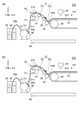
図3(a)及び図3(b)に示すように、第1状態ST1において、第1ノズル排出口11oの高さ及び第2ノズル排出口12oの高さは、第1管21の高さ以上である。図4(a)及び図4(b)に示すように、第2状態ST2において、第1ノズル排出口11oの高さ及び第2ノズル排出口12oの高さは、第1管21の高さよりも低い。高さは、例えばZ軸方向における位置である。高さは、例えば基体48を基準としたZ軸方向における位置である。このような第1状態ST1により、以下に説明するように、均一な塗布膜を形成できる。
As shown in FIGS. 3A and 3B, in the first state ST1, the height of the first nozzle discharge port 11o and the height of the second nozzle discharge port 12o are the heights of the first pipe 21. That is all. As shown in FIGS. 4A and 4B, in the second state ST2, the height of the first nozzle discharge port 11o and the height of the second nozzle discharge port 12o are higher than the height of the first pipe 21. Is also low. The height is, for example, a position in the Z-axis direction. The height is, for example, a position in the Z-axis direction with respect to the substrate 48. With such a first state ST1, a uniform coating film can be formed as described below.
例えば、第1管21の一部の内部に空気などの気体が残っている状態で、第1管21に液50が供給される場合がある。例えば、第1ノズル11及び第2ノズル12の少なくともいずれかに空気などの気体が残っている場合がある。このような状態で、液50が第1管21に供給されると、気体が排出されずに、気体が残っていないノズルから液が排出される状態が続きやすい。気体が排出されないと、液50の均一な排出が困難になる。液50が均一に排出されないと、被塗布部材81に液50が不均一に塗布されやすい。
For example, the liquid 50 may be supplied to the first pipe 21 in a state where a gas such as air remains inside a part of the first pipe 21. For example, gas such as air may remain in at least one of the first nozzle 11 and the second nozzle 12. When the liquid 50 is supplied to the first pipe 21 in such a state, the state in which the gas is not discharged and the liquid is easily discharged from the nozzle in which no gas remains is likely to continue. If the gas is not discharged, it becomes difficult to uniformly discharge the liquid 50. If the liquid 50 is not uniformly discharged, the liquid 50 tends to be unevenly applied to the member to be coated 81.
実施形態においては、上記の第1状態ST1及び第2状態ST2が形成可能である。例えば、第1ポンプ31は、第1状態ST1において第1流入口21iに液50を供給して、第1ノズル排出口11o及び第2ノズル排出口12oから液50を排出させることが可能である。この時、第1状態ST1においては、第1ノズル排出口11oの高さ及び第2ノズル排出口12oの高さは、第1管21の高さ以上である。このような第1状態ST1で第1管21を介して、第1ノズル11及び第2ノズル12に液50が供給されると、第1管21、第1ノズル12及び第2ノズル12に気体が存在する場合も、気体をこれらのノズルから排出させることができる。これにより、均一な排出が可能になる。
In the embodiment, the above-mentioned first state ST1 and second state ST2 can be formed. For example, the first pump 31 can supply the liquid 50 to the first inflow port 21i in the first state ST1 and discharge the liquid 50 from the first nozzle discharge port 11o and the second nozzle discharge port 12o. .. At this time, in the first state ST1, the height of the first nozzle discharge port 11o and the height of the second nozzle discharge port 12o are equal to or higher than the height of the first pipe 21. When the liquid 50 is supplied to the first nozzle 11 and the second nozzle 12 via the first pipe 21 in such a first state ST1, gas is supplied to the first pipe 21, the first nozzle 12, and the second nozzle 12. Gas can also be expelled from these nozzles if is present. This enables uniform discharge.
第2状態ST2において、第1ノズル11及び第2ノズル12から液50を排出させて、被塗布部材81に液50を塗布する。塗布された液50は、均一である。
In the second state ST2, the liquid 50 is discharged from the first nozzle 11 and the second nozzle 12, and the liquid 50 is applied to the member to be coated 81. The applied liquid 50 is uniform.
このように、第1ポンプ31は、第1状態ST1において第1流入口21iに液50を供給して、第1ノズル11及び第2ノズル12の少なくともいずれかから、第1ノズル11及び第2ノズル12の少なくともいずれかの中の気体を排出させることが可能である。実施形態によれば、均一な塗布膜を形成できる。
As described above, the first pump 31 supplies the liquid 50 to the first inflow port 21i in the first state ST1, and the first nozzle 11 and the second nozzle 11 and the second from at least one of the first nozzle 11 and the second nozzle 12. It is possible to expel the gas in at least one of the nozzles 12. According to the embodiment, a uniform coating film can be formed.
第1ポンプ31は、第2状態ST2において第1流入口21iに液50を供給して、第1ノズル11及び第2ノズル12から液50を排出させて、被塗布部材81に液50を塗布することが可能である。塗布された液50から得られる塗布膜が均一である。このように、第1ノズル排出口11o及び第2ノズル排出口12oは、被塗布部材81に液50を塗布することが可能である。
The first pump 31 supplies the liquid 50 to the first inflow port 21i in the second state ST2, discharges the liquid 50 from the first nozzle 11 and the second nozzle 12, and applies the liquid 50 to the member to be coated 81. It is possible to do. The coating film obtained from the applied liquid 50 is uniform. As described above, the first nozzle discharge port 11o and the second nozzle discharge port 12o can apply the liquid 50 to the member to be coated 81.
例えば、上記の第1状態ST1を経ないで、第2状態ST2で塗布を行う場合、複数のノズルの少なくとも1つの中に気体が残り易い。気体が残ったまま、他のノズルから液50が排出されてしまう。このため、気体が残り続ける。気体が残ったまま塗布を行うと、塗布が不均一になり易い。
For example, when coating is performed in the second state ST2 without going through the first state ST1 described above, gas tends to remain in at least one of the plurality of nozzles. The liquid 50 is discharged from another nozzle while the gas remains. Therefore, the gas continues to remain. If the coating is performed with the gas remaining, the coating tends to be uneven.
図3(a)及び図3(b)に示すように、塗布装置110は、ノズル液受け入れ部29をさらに含んでも良い。ノズル液受け入れ部29は、例えば、第1状態ST1において、第1ノズル排出口11o及び第2ノズル排出口12oから排出された液50を受け入れることが可能である。気体を除去する第1状態ST1においては、第1ノズル排出口11o及び第2ノズル排出口12oの高さが高い。このような第1状態ST1において第1ノズル排出口11o及び第2ノズル排出口12oから液50を排出させると、液50は、これらのノズルを伝って第1管21に向けて移動してしまう。第1管21などが液50で汚れてしまう。ノズル液受け入れ部29により液50を取り込むことで、汚れが抑制できる。実施形態において、ノズル排出口の下に、ノズル液受け入れ部が設けられても良い。
As shown in FIGS. 3 (a) and 3 (b), the coating device 110 may further include a nozzle liquid receiving unit 29. The nozzle liquid receiving unit 29 can receive, for example, the liquid 50 discharged from the first nozzle discharge port 11o and the second nozzle discharge port 12o in the first state ST1. In the first state ST1 for removing gas, the heights of the first nozzle discharge port 11o and the second nozzle discharge port 12o are high. When the liquid 50 is discharged from the first nozzle discharge port 11o and the second nozzle discharge port 12o in such a first state ST1, the liquid 50 moves toward the first pipe 21 along these nozzles. .. The first pipe 21 and the like get dirty with the liquid 50. Dirt can be suppressed by taking in the liquid 50 by the nozzle liquid receiving unit 29. In the embodiment, a nozzle liquid receiving portion may be provided below the nozzle discharge port.
図5(a)及び図5(b)は、第2状態ST2において、液50がノズルから排出される状態を例示している。これらの図は、液50を被塗布部材81に塗布する動作に対応する。
FIGS. 5 (a) and 5 (b) exemplify a state in which the liquid 50 is discharged from the nozzle in the second state ST2. These figures correspond to the operation of applying the liquid 50 to the member to be coated 81.
図1、図2、図5(a)及び図5(b)に示すように、塗布装置110は、塗布バー42を含む。塗布バー42は、被塗布部材81と対向可能である。塗布バー42は、例えばY軸方向に沿って延びる。図5(a)及び図5(b)に示すように、第2状態ST2において、第1ノズル排出口11o及び第2ノズル排出口12oは、液50を塗布バー42に向けて供給することが可能である。第1ポンプ31が液50を第1管21に供給することで、これらのノズルから液50が塗布バー42に向けて供給される。
As shown in FIGS. 1, 2, 5 (a) and 5 (b), the coating device 110 includes a coating bar 42. The coating bar 42 can face the member to be coated 81. The coating bar 42 extends, for example, along the Y-axis direction. As shown in FIGS. 5A and 5B, in the second state ST2, the first nozzle discharge port 11o and the second nozzle discharge port 12o may supply the liquid 50 toward the coating bar 42. It is possible. When the first pump 31 supplies the liquid 50 to the first pipe 21, the liquid 50 is supplied from these nozzles toward the coating bar 42.
図5(a)及び図5(b)に示すように、例えば、塗布バー42は、塗布バー42と被塗布部材81との間に、液50のメニスカス51Mを形成可能である。メニスカス51Mが形成されることで、より均一な塗布膜51Fが得やすい。
As shown in FIGS. 5 (a) and 5 (b), for example, the coating bar 42 can form a meniscus 51M of the liquid 50 between the coating bar 42 and the member to be coated 81. By forming the meniscus 51M, a more uniform coating film 51F can be easily obtained.
第2状態ST2において、第1ノズル排出口11o及び第2ノズル排出口12oは、塗布バー42に接しても良い。より安定した塗布が行われる。
In the second state ST2, the first nozzle discharge port 11o and the second nozzle discharge port 12o may be in contact with the coating bar 42. More stable application is performed.
図1及び図2に示すように、この例では、塗布装置110は、被塗布部材保持部85及び塗布バー位置制御部42Cをさらに含む。被塗布部材保持部85は、被塗布部材81を保持する。この例では、被塗布部材保持部85は、被塗布部材81を搬送可能である。この例では、被塗布部材81は、フィルム状である。被塗布部材保持部85は、フィルム状の被塗布部材81を搬送可能なローラーを含む。
As shown in FIGS. 1 and 2, in this example, the coating device 110 further includes a member to be coated member holding unit 85 and a coating bar position control unit 42C. The member to be coated 85 holds the member 81 to be coated. In this example, the member to be applied holding portion 85 can convey the member to be applied 81. In this example, the member to be coated 81 is in the form of a film. The member to be coated member holding portion 85 includes a roller capable of transporting the film-shaped member to be coated 81.
塗布バー位置制御部42Cは、塗布バー42と被塗布部材保持部85との間の相対的な位置を制御可能である。塗布バー位置制御部42Cは、塗布バー42と被塗布部材81との間の相対的な位置を制御可能である。塗布バー位置制御部42Cは、例えば、X軸方向、Y軸方向及びZ軸方向の少なくともいずれかの方向において、塗布バー42と被塗布部材保持部85との間の相対的な位置を制御可能である。塗布バー位置制御部42Cとして、例えば、複数の方向に可動のアクチュエータなどが用いられて良い。
The coating bar position control unit 42C can control the relative position between the coating bar 42 and the member to be coated member holding portion 85. The coating bar position control unit 42C can control the relative position between the coating bar 42 and the member to be coated 81. The coating bar position control unit 42C can control the relative position between the coating bar 42 and the member to be coated member holding portion 85 in at least one of the X-axis direction, the Y-axis direction, and the Z-axis direction, for example. Is. As the coating bar position control unit 42C, for example, an actuator that can move in a plurality of directions may be used.
図1及び図2に示すように、塗布装置110は、検出部42Mをさらに含んでも良い。検出部42Mは、例えば、塗布バー42と被塗布部材保持部85との間の相対的な位置を検出可能である。検出部42Mは、例えば、光学センサなどを含んで良い。検出部42Mによる検出結果に基づいて、塗布バー位置制御部42Cは、塗布バー42と被塗布部材保持部85との間の相対的な位置を制御しても良い。
As shown in FIGS. 1 and 2, the coating device 110 may further include a detection unit 42M. The detection unit 42M can detect, for example, the relative position between the coating bar 42 and the member to be coated member holding portion 85. The detection unit 42M may include, for example, an optical sensor or the like. Based on the detection result by the detection unit 42M, the coating bar position control unit 42C may control the relative position between the coating bar 42 and the member to be coated member holding unit 85.
保持部41は、第1ノズル11と塗布バー42との間の相対的な位置関係、及び、第2ノズル12と塗布バー42との間の相対的な位置関係を制御可能でも良い。相対的な位置関係は、例えば、X軸方向、Y軸方向及びZ軸方向の少なくともいずれかの方向における位置関係で良い。
The holding portion 41 may be able to control the relative positional relationship between the first nozzle 11 and the coating bar 42 and the relative positional relationship between the second nozzle 12 and the coating bar 42. The relative positional relationship may be, for example, a positional relationship in at least one of the X-axis direction, the Y-axis direction, and the Z-axis direction.
図1及び図2に示すように、この例では、保持部41は、ノズル間隔制御部41Cを含む。例えば、ノズル間隔制御部41Cは、第1ノズル11と第2ノズル12との間の間隔を制御可能である。間隔は、例えば、Y軸方向に沿った距離である。1つの例において、バー状の保持部41の一部に凹部が設けられ、その凹部がノズル間隔制御部41Cとなる。複数の凹部を設けておき、複数の凹部の所望の位置にノズルを固定することで、複数のノズルどうしの間隔が可変で制御できる。複数のノズルの保持の構造、及び、複数のノズルの間隔の制御方法は任意である。液50の特性(例えば粘度度など)に応じて、複数のノズルどうしの間隔などを変更して良い。凹部は、例えば、溝またはスペーサなどにより形成できる。
As shown in FIGS. 1 and 2, in this example, the holding unit 41 includes the nozzle spacing control unit 41C. For example, the nozzle spacing control unit 41C can control the spacing between the first nozzle 11 and the second nozzle 12. The interval is, for example, a distance along the Y-axis direction. In one example, a recess is provided in a part of the bar-shaped holding portion 41, and the recess serves as a nozzle spacing control unit 41C. By providing a plurality of recesses and fixing the nozzles at desired positions of the plurality of recesses, the interval between the plurality of nozzles can be variably controlled. The structure for holding the plurality of nozzles and the method for controlling the spacing between the plurality of nozzles are arbitrary. The spacing between the plurality of nozzles may be changed according to the characteristics of the liquid 50 (for example, viscosity). The recess can be formed, for example, by a groove or a spacer.
実施形態において、第1ノズル11は針状である。針状の第1ノズル11を用いることで、例えば、液50の排出量を高い精度で制御できる。ノズルが針状であると、例えば、複数のノズルの先端が塗布バー42に接触させ易い。針状のノズルにおいて、高い柔軟性が得られる。高い柔軟性により、例えば、塗布バー42の振動などによりノズルが損傷することが抑制できる。針状のノズルにおいて、ノズルの長さは、例えば10mm以上100mm以下であり、ノズルの内径は、例えば1mm以上2mm以下である。ノズルの先端の端面とノズルの延びる方向との間の角度は、例えば約90度(例えば75度以上105度以下)である。このような形状により、例えば、塗布バー42に傷が生じることが抑制できる。このような形状により、例えば、塗布バー42への液50の供給が安定化し易い。
In the embodiment, the first nozzle 11 is needle-shaped. By using the needle-shaped first nozzle 11, for example, the discharge amount of the liquid 50 can be controlled with high accuracy. When the nozzles are needle-shaped, for example, the tips of a plurality of nozzles are likely to come into contact with the coating bar 42. High flexibility is obtained in the needle-shaped nozzle. Due to the high flexibility, it is possible to prevent the nozzle from being damaged by, for example, vibration of the coating bar 42. In the needle-shaped nozzle, the length of the nozzle is, for example, 10 mm or more and 100 mm or less, and the inner diameter of the nozzle is, for example, 1 mm or more and 2 mm or less. The angle between the end face of the tip of the nozzle and the extending direction of the nozzle is, for example, about 90 degrees (for example, 75 degrees or more and 105 degrees or less). With such a shape, for example, it is possible to prevent the coating bar 42 from being scratched. With such a shape, for example, the supply of the liquid 50 to the coating bar 42 can be easily stabilized.
図2に示すように、第1管21は、4以上の流出口を含んでも良い。4以上の流出口のそれぞれに、ノズルが接続される。例えば、第1管21は、2ずつに分岐する複数の分岐部21Bを含む。例えば、第1管21は、2のn乗(nは1以上の整数)の流出口を含む。液50の均一な排出がより容易になる。
As shown in FIG. 2, the first pipe 21 may include four or more outlets. Nozzles are connected to each of the four or more outlets. For example, the first pipe 21 includes a plurality of branch portions 21B that branch into two. For example, the first pipe 21 includes an outlet of 2 to the nth root (n is an integer of 1 or more). Uniform discharge of the liquid 50 becomes easier.
実施形態において、第1管21は、逆止弁21vを含んでも良い。逆止弁21vにより、気体の逆流を抑制できる。例えば、気体(空気)の流入が抑制できる。
In the embodiment, the first pipe 21 may include a check valve 21v. The check valve 21v can suppress the backflow of gas. For example, the inflow of gas (air) can be suppressed.
実施形態において、第1ポンプ31は、ダイヤフラムポンプを含んでも良い。ダイヤフラムポンプにより、液50を安定して均一に供給し易くなる。例えば、種々の溶媒が適用可能である。例えば、「呼び水」が不要である。例えば、高い耐久性が得られる。例えば、空運転も可能であり、乾燥に用いることができる。
In the embodiment, the first pump 31 may include a diaphragm pump. The diaphragm pump facilitates stable and uniform supply of the liquid 50. For example, various solvents are applicable. For example, "priming water" is unnecessary. For example, high durability can be obtained. For example, it can be operated idle and can be used for drying.
図1及び図2に示すように、塗布装置110は、管高さ制御部43を含んでも良い。管高さ制御部43は、第1管21の高さを制御する。例えば、第1状態ST1、第2状態ST2、及び、それらの間の状態において、第1ノズル11及び第2ノズル12の高さの変化に応じて第1管21が動く場合がある。第1管21が動いて第1管21が所望の高さでなくなる場合がある。管高さ制御部43が設けられることで、第1管21の高さが所望の状態に制御される。例えば、第1状態ST1において、第1管21中の最高の高さが所望以下になるように制限される。この例では、管高さ制御部43は、Y軸方向に延びるバー状(または板状)である。
As shown in FIGS. 1 and 2, the coating device 110 may include a pipe height control unit 43. The pipe height control unit 43 controls the height of the first pipe 21. For example, in the first state ST1, the second state ST2, and the state between them, the first tube 21 may move according to the change in the height of the first nozzle 11 and the second nozzle 12. The first pipe 21 may move and the first pipe 21 may not have a desired height. By providing the pipe height control unit 43, the height of the first pipe 21 is controlled to a desired state. For example, in the first state ST1, the maximum height in the first tube 21 is limited to be less than or equal to the desired height. In this example, the pipe height control unit 43 has a bar shape (or a plate shape) extending in the Y-axis direction.
図1及び図2に示すように、塗布装置110は、乾燥部45をさらに含んでも良い。乾燥部45は、被塗布部材81に塗布された液50を乾燥させることが可能である。乾燥部45は、例えば、エアノズルを含んでも良い。
As shown in FIGS. 1 and 2, the coating device 110 may further include a drying portion 45. The drying unit 45 can dry the liquid 50 applied to the member to be coated 81. The drying unit 45 may include, for example, an air nozzle.
図1及び図2に示すように、第1管21は、排出バルブ21uを含んでも良い。排出バルブ21uの動作により、第1管21の中の液50を、例えば、排出管56pを介して、容器56に排出させることができる。
As shown in FIGS. 1 and 2, the first pipe 21 may include a discharge valve 21u. By the operation of the discharge valve 21u, the liquid 50 in the first pipe 21 can be discharged to the container 56 via, for example, the discharge pipe 56p.
図2に示すように、この例では、塗布装置110は、第2管22、第2ポンプ32、第3ノズル13及び第4ノズル14をさらに含む。第2管22は、第2流入口22i、第3流出口22c、及び、第4流出口22dを含む。
As shown in FIG. 2, in this example, the coating device 110 further includes a second tube 22, a second pump 32, a third nozzle 13, and a fourth nozzle 14. The second pipe 22 includes a second inlet 22i, a third outlet 22c, and a fourth outlet 22d.
第2ポンプ32は、第2流入口22iに向けて液50を供給可能である。例えば、容器55中の液50が、管28bを介して第2ポンプ32に供給される。
The second pump 32 can supply the liquid 50 toward the second inflow port 22i. For example, the liquid 50 in the container 55 is supplied to the second pump 32 via the pipe 28b.
第3ノズル13は、第3ノズル流入口13i及び第3ノズル排出口13oを含む。第3ノズル流入口13iは、第3流出口22cと接続される。第3ノズル排出口13oは、第2管22を通過した液50を排出可能である。
The third nozzle 13 includes the third nozzle inlet 13i and the third nozzle outlet 13o. The third nozzle inlet 13i is connected to the third outlet 22c. The third nozzle discharge port 13o can discharge the liquid 50 that has passed through the second pipe 22.
第4ノズル14は、第4ノズル流入口14i及び第4ノズル排出口14oを含む。第4ノズル流入口14iは、第4流出口22dと接続される。第4ノズル排出口14oは、第2管22を通過した液50を排出可能である。
The fourth nozzle 14 includes a fourth nozzle inlet 14i and a fourth nozzle outlet 14o. The fourth nozzle inlet 14i is connected to the fourth outlet 22d. The fourth nozzle discharge port 14o can discharge the liquid 50 that has passed through the second pipe 22.
保持部41は、第3ノズル13及び第4ノズル14をさらに保持する。
The holding unit 41 further holds the third nozzle 13 and the fourth nozzle 14.
図6(a)、図6(b)、図7(a)、図7(b)、図8(a)及び図8(b)は、第1実施形態に係る塗布装置を例示する模式的側面図である。
図6(a)は、第1状態ST1における第3ノズル13を例示している。図6(b)は、第1状態ST1における第4ノズル14を例示している。図7(a)は、第2状態ST1における第3ノズル13を例示している。図7(b)は、第2状態ST2における第4ノズル14を例示している。図8(a)は、第2状態ST2の第3ノズル13による塗布を例示している。図8(b)は、第2状態ST2の第4ノズル14による塗布を例示している。 6 (a), 6 (b), 7 (a), 7 (b), 8 (a) and 8 (b) are schematics illustrating the coating apparatus according to the first embodiment. It is a side view.
FIG. 6A illustrates thethird nozzle 13 in the first state ST1. FIG. 6B illustrates the fourth nozzle 14 in the first state ST1. FIG. 7A illustrates the third nozzle 13 in the second state ST1. FIG. 7B illustrates the fourth nozzle 14 in the second state ST2. FIG. 8A exemplifies the coating by the third nozzle 13 of the second state ST2. FIG. 8B exemplifies the coating by the fourth nozzle 14 of the second state ST2.
図6(a)は、第1状態ST1における第3ノズル13を例示している。図6(b)は、第1状態ST1における第4ノズル14を例示している。図7(a)は、第2状態ST1における第3ノズル13を例示している。図7(b)は、第2状態ST2における第4ノズル14を例示している。図8(a)は、第2状態ST2の第3ノズル13による塗布を例示している。図8(b)は、第2状態ST2の第4ノズル14による塗布を例示している。 6 (a), 6 (b), 7 (a), 7 (b), 8 (a) and 8 (b) are schematics illustrating the coating apparatus according to the first embodiment. It is a side view.
FIG. 6A illustrates the
図6(a)及び図6(b)に示すように、第1状態ST1において、第3ノズル排出口13oの高さ及び第4ノズル排出口14oの高さは、第2管22の高さ以上である。
As shown in FIGS. 6A and 6B, in the first state ST1, the height of the third nozzle discharge port 13o and the height of the fourth nozzle discharge port 14o are the heights of the second pipe 22. That is all.
図7(a)及び図7(b)に示すように、第2状態ST2において、第3ノズル排出口13oの高さ及び第4ノズル排出口14oの高さは、第2管22の高さよりも低い。
As shown in FIGS. 7 (a) and 7 (b), in the second state ST2, the height of the third nozzle discharge port 13o and the height of the fourth nozzle discharge port 14o are higher than the height of the second pipe 22. Is also low.
このような第1状態ST1において、第3ノズル13及び第4ノズル14から気体が排出できる。図8(a)及び図8(b)に示すように、第2状態ST2において、第3ノズル13及び第4ノズル14から液50を排出させて、被塗布部材81に液50が塗布できる。被塗布部材81に液50による塗布膜51Fが形成できる。
In such a first state ST1, gas can be discharged from the third nozzle 13 and the fourth nozzle 14. As shown in FIGS. 8A and 8B, in the second state ST2, the liquid 50 can be discharged from the third nozzle 13 and the fourth nozzle 14 to apply the liquid 50 to the member to be coated 81. A coating film 51F made of the liquid 50 can be formed on the member to be coated 81.
図6(a)及び図6(b)に示すように、実施形態において、第2管22は、逆止弁22vを含んでも良い。逆止弁22vにより、気体の逆流を抑制できる。例えば、気体(空気)の流入が抑制できる。
As shown in FIGS. 6 (a) and 6 (b), in the embodiment, the second pipe 22 may include a check valve 22v. The check valve 22v can suppress the backflow of gas. For example, the inflow of gas (air) can be suppressed.
図2、図6(a)及び図6(b)に示すように、第2管22は、排出バルブ22uを含んでも良い。排出バルブ22uの動作により、第2管22の中の液50を、例えば、排出管56qを介して、容器56に排出させることができる。
As shown in FIGS. 2, 6 (a) and 6 (b), the second pipe 22 may include a discharge valve 22u. By the operation of the discharge valve 22u, the liquid 50 in the second pipe 22 can be discharged to the container 56 via, for example, the discharge pipe 56q.
実施形態において、塗布バー42の断面形状は、任意である。塗布バー42の断面形状は、例えば、円形、偏平円形または多角形である。断面形状の一部が曲線状で、他の部分が直線状でも良い。例えば、塗布バー42の、被塗布部材81に対向する面の断面形状は曲線状でも良い。
In the embodiment, the cross-sectional shape of the coating bar 42 is arbitrary. The cross-sectional shape of the coating bar 42 is, for example, circular, flat circular or polygonal. A part of the cross-sectional shape may be curved, and the other part may be straight. For example, the cross-sectional shape of the surface of the coating bar 42 facing the member to be coated 81 may be curved.
塗布バー42は、例えば、ステンレススチール、アルミニウム、チタン及びガラスよりなる群から選択された少なくとも1つを含む。塗布バー42は、ステレススチールまたはアルミニウムを含むことがより好ましい。これにより、塗布バー42の加工が容易になる。1つの例において、塗布バー42の表面は鏡面である。別の例において、塗布バー42の表面は、凹凸を含んでも良い。
The coating bar 42 contains, for example, at least one selected from the group consisting of stainless steel, aluminum, titanium and glass. The coating bar 42 more preferably contains stelessteel or aluminum. This facilitates the processing of the coating bar 42. In one example, the surface of the coating bar 42 is a mirror surface. In another example, the surface of the coating bar 42 may include irregularities.
図9は、第1実施形態に係る塗布装置の一部を例示する模式的側面図である。
図9は、塗布バー42の一部を例示している。図6に示すように、実施形態において、塗布バー42の表面42Fは凹凸42dpを含んでも良い。凹凸42dpの最大高さRzは、例えば、5μm以上50μm以下である。凹凸42dpの算術平均表面粗さRaは、例えば、1μm以上10μm以下である。例えば、サンドブラスト法により、凹凸42dpが作製されて良い。凹凸42dpが設けられことで、例えば、液50に対しての高い濡れ性が得られる。 FIG. 9 is a schematic side view illustrating a part of the coating device according to the first embodiment.
FIG. 9 illustrates a part of thecoating bar 42. As shown in FIG. 6, in the embodiment, the surface 42F of the coating bar 42 may include the unevenness 42dp. The maximum height Rz of the unevenness 42 dp is, for example, 5 μm or more and 50 μm or less. The arithmetic average surface roughness Ra of the unevenness of 42 dp is, for example, 1 μm or more and 10 μm or less. For example, the unevenness 42dp may be produced by the sandblasting method. By providing the unevenness 42 dp, for example, high wettability to the liquid 50 can be obtained.
図9は、塗布バー42の一部を例示している。図6に示すように、実施形態において、塗布バー42の表面42Fは凹凸42dpを含んでも良い。凹凸42dpの最大高さRzは、例えば、5μm以上50μm以下である。凹凸42dpの算術平均表面粗さRaは、例えば、1μm以上10μm以下である。例えば、サンドブラスト法により、凹凸42dpが作製されて良い。凹凸42dpが設けられことで、例えば、液50に対しての高い濡れ性が得られる。 FIG. 9 is a schematic side view illustrating a part of the coating device according to the first embodiment.
FIG. 9 illustrates a part of the
(第2実施形態)
第2実施形態は、塗布方法に係る。実施形態に係る塗布方法においては、例えば、第1実施形態に関して説明した塗布装置110(及びその変形)を用いて塗布が行われる。 (Second Embodiment)
The second embodiment relates to a coating method. In the coating method according to the embodiment, for example, coating is performed using the coating device 110 (and a modification thereof) described with respect to the first embodiment.
図10は、第2実施形態に係る塗布方法を例示するフローチャート図である。
図10に示すように、第1状態ST1において第1流入口21iに液50を供給して、第1ノズル11及び第2ノズル12の少なくともいずれかから、第1ノズル11及び第2ノズル12の上記の少なくともいずれの中の気体を排出させる(ステップS110)。 FIG. 10 is a flowchart illustrating the coating method according to the second embodiment.
As shown in FIG. 10, in the first state ST1, the liquid 50 is supplied to thefirst inflow port 21i, and from at least one of the first nozzle 11 and the second nozzle 12, the first nozzle 11 and the second nozzle 12 Discharge the gas in at least one of the above (step S110).
図10に示すように、第1状態ST1において第1流入口21iに液50を供給して、第1ノズル11及び第2ノズル12の少なくともいずれかから、第1ノズル11及び第2ノズル12の上記の少なくともいずれの中の気体を排出させる(ステップS110)。 FIG. 10 is a flowchart illustrating the coating method according to the second embodiment.
As shown in FIG. 10, in the first state ST1, the liquid 50 is supplied to the
気体の排出の後に、第2状態ST2において第1流入口21iに液50を供給して、第1ノズル11及び第2ノズル12から液50を排出させて、被塗布部材81に液50を塗布する(ステップS120)。
After the gas is discharged, the liquid 50 is supplied to the first inflow port 21i in the second state ST2, the liquid 50 is discharged from the first nozzle 11 and the second nozzle 12, and the liquid 50 is applied to the member to be coated 81. (Step S120).
実施形態に係る塗布方法においては、塗布の前の第1状態ST1において、第1ノズル排出口11oの高さ及び第2ノズル排出口12o高さは、第1管21の高さ以上である。この第1状態ST1おいて、液50が供給されることで、気体が効率的に排出できる。実施形態によれば、均一な塗布膜を形成できる塗布方法が提供できる。
In the coating method according to the embodiment, in the first state ST1 before coating, the height of the first nozzle discharge port 11o and the height of the second nozzle discharge port 12o are equal to or higher than the height of the first pipe 21. By supplying the liquid 50 in this first state ST1, the gas can be efficiently discharged. According to the embodiment, it is possible to provide a coating method capable of forming a uniform coating film.
以下、実施形態に係る塗布装置及び塗布方法の例について説明する。
例えば、塗布装置110による塗布により、太陽電池が形成できる。1つの例において、ポンプの数は、4である。1つのポンプに接続された管は、4のノズルに接続される。ノズルの総数は、16である。 Hereinafter, an example of the coating apparatus and the coating method according to the embodiment will be described.
For example, a solar cell can be formed by coating with thecoating device 110. In one example, the number of pumps is four. The tube connected to one pump is connected to four nozzles. The total number of nozzles is 16.
例えば、塗布装置110による塗布により、太陽電池が形成できる。1つの例において、ポンプの数は、4である。1つのポンプに接続された管は、4のノズルに接続される。ノズルの総数は、16である。 Hereinafter, an example of the coating apparatus and the coating method according to the embodiment will be described.
For example, a solar cell can be formed by coating with the
例えば、被塗布部材81は、ロール状のPETフィルムである。PETフィルムの幅は、例えば、330mmである。PETフィルム上にロールtoロール対応のスパッタ装置により光透過性で、幅が300mmの電極が作成される。電極のシート抵抗は、例えば、5Ω/□である。電極は、例えば、ITO膜/Ag合金/ITO膜の積層構造を有する。例えば、複数の電極が設けられる。複数の電極の1つの長さは、例えば、約20mmである。複数の電極どうしの間隔は、例えば50μmである。
For example, the member to be coated 81 is a roll-shaped PET film. The width of the PET film is, for example, 330 mm. A roll-to-roll sputter device on the PET film creates a light-transmitting electrode with a width of 300 mm. The sheet resistance of the electrode is, for example, 5Ω / □. The electrode has, for example, an ITO film / Ag alloy / ITO film laminated structure. For example, a plurality of electrodes are provided. The length of one of the plurality of electrodes is, for example, about 20 mm. The distance between the plurality of electrodes is, for example, 50 μm.
塗布バー42の断面は、円状である。円の半径は、10mmである。塗布バー42の長さは、300mmである。塗布バー42は、例えば、ステンレス(例えばSUS303)を含む。
The cross section of the coating bar 42 is circular. The radius of the circle is 10 mm. The length of the coating bar 42 is 300 mm. The coating bar 42 contains, for example, stainless steel (eg, SUS303).
例えば、保持部41の長さは320mmである。保持部41に、複数の穴が設けられる。複数の穴のピッチは18mmである。複数の穴のそれぞれにノズルが固定される。
For example, the length of the holding portion 41 is 320 mm. The holding portion 41 is provided with a plurality of holes. The pitch of the plurality of holes is 18 mm. Nozzles are fixed in each of the multiple holes.
ノズルは、ステンレス製のロック基を含む。ノズルの長さは、50mmである。管(第1管21など)は、ポリテトラフルオロエチレン製チューブである。ノズルと管とは、着脱可能なジョイントにより接続される。管がポンプに接続される。
The nozzle contains a stainless steel lock group. The length of the nozzle is 50 mm. The tube (first tube 21, etc.) is a tube made of polytetrafluoroethylene. The nozzle and the tube are connected by a removable joint. The pipe is connected to the pump.
1つの例において、液50により、ホール輸送層が形成される。この場合、液50は、PEDOT及びPSSを含む水溶液である。
In one example, the liquid 50 forms a hole transport layer. In this case, the liquid 50 is an aqueous solution containing PEDOT and PSS.
例えば、アクチュエータにより、塗布バー42と被塗布部材81との間の相対的な位置関係が制御される。
For example, the actuator controls the relative positional relationship between the coating bar 42 and the member to be coated 81.
例えば、ノズルを水平状態にする。この時、ノズルの先端の高さは、管(第1管21)の高さ以上である。管高さ制御部43により管の高さが適切に制御される。このような第1状態ST1において、液50が供給され、ノズル中の空気が排出される。
For example, make the nozzle horizontal. At this time, the height of the tip of the nozzle is equal to or higher than the height of the pipe (first pipe 21). The height of the pipe is appropriately controlled by the pipe height control unit 43. In such a first state ST1, the liquid 50 is supplied and the air in the nozzle is discharged.
この後、ノズルの先端を下方向に約50°傾斜させる。このとき、必要に応じて、管高さ制御部43が除去されても良い。ノズルの先端が下に傾いた状態で、ノズルの先端を塗布バー42に接触させる。この第2状態ST2において、ポンプが液50を供給する前では、ノズルから液50は、実質的に排出されない。
After this, tilt the tip of the nozzle downward by about 50 °. At this time, the pipe height control unit 43 may be removed if necessary. With the tip of the nozzle tilted downward, the tip of the nozzle is brought into contact with the coating bar 42. In this second state ST2, the liquid 50 is not substantially discharged from the nozzle before the pump supplies the liquid 50.
例えば、被塗布部材81を搬送しながら、ポンプにより液50を連続的に供給して塗布膜51Fが得られる。被塗布部材81の移動速度は、例えば、5m/sである。乾燥部45により、塗布された液50に、加熱した乾燥空気を吹き付ける。液50から塗布膜51Fが得られる。
For example, the liquid 50 is continuously supplied by a pump while transporting the member to be coated 81 to obtain the coating film 51F. The moving speed of the member to be coated 81 is, for example, 5 m / s. The dried portion 45 blows heated dry air onto the applied liquid 50. The coating film 51F is obtained from the liquid 50.
塗布の終了後、例えば、ノズルの先端を管(第1管21など)よりも高くしても良い。排液バルブ(排出バルブ21uなど)を開けて、管内の液50が回収されても良い。
After the application is completed, for example, the tip of the nozzle may be higher than the tube (first tube 21 or the like). The liquid 50 in the pipe may be collected by opening the drain valve (drain valve 21u or the like).
実施形態において、上記の液50の塗布の後に、別の液がさらに塗布されても良い。別の液50は、例えば、半導体材料を含む。別の液50は、例えば、PTB7([ポリ{4,8-ビス[(2-エチルヘキシル)オキシ]ベンゾ[1,2-b:4,5-b’]ジチオフェン-2,6-ジイル-1t-alt-3-フルオロ-2-[(2-エチルヘキシル)カルボニル]チエノ[3,4-b]チオフェン-4,6-ジイル}])と、PC70BM([6,6]フェニルC71ブチル酸メチルエスター)と、を含む。PTB7は、例えばp形半導体である。PC70BMは、例えば、n形半導体である。別の液50は、例えば、モノクロロベンゼンをさらに含む。1mLのモノクロロベンゼンに対して、PTB7の量は8mgである。1mLのモノクロロベンゼンに対して、PC70BMの量は12mgである。別の液50は、有機半導体を含む分散液である。
In the embodiment, after the application of the above liquid 50, another liquid may be further applied. Another liquid 50 contains, for example, a semiconductor material. Another liquid 50 is, for example, PTB7 ([poly {4,8-bis [(2-ethylhexyl) oxy] benzo [1,2-b: 4,5-b'] dithiophene-2,6-diyl-1t). -Alt-3-fluoro-2-[(2-ethylhexyl) carbonyl] thieno [3,4-b] thiophene-4,6-diyl}]) and PC70BM ([6,6] phenylC71 methylester butylate) ) And, including. PTB7 is, for example, a p-type semiconductor. The PC70BM is, for example, an n-type semiconductor. Another liquid 50 further comprises, for example, monochlorobenzene. For 1 mL of monochlorobenzene, the amount of PTB7 is 8 mg. For 1 mL of monochlorobenzene, the amount of PC70BM is 12 mg. Another liquid 50 is a dispersion liquid containing an organic semiconductor.
別の液50は、例えば、太陽電池の半導体膜となる。別の液50の塗布において、塗布バー42と被塗布部材81との間の最小間隙距離は、300μmである。被塗布部材81の移動速度は、例えば、5/sである。塗布後に、乾燥部45により乾燥が行われる。
Another liquid 50 is, for example, a semiconductor film of a solar cell. In the application of another liquid 50, the minimum gap distance between the application bar 42 and the member to be applied 81 is 300 μm. The moving speed of the member to be coated 81 is, for example, 5 / s. After application, drying is performed by the drying portion 45.
例えば、有機半導体を用いた有機薄膜太陽電池、または、有機/無機ハイブリッド太陽電池がある。これらの太陽電池を塗布法により作製することで、コストを低くできる。複数のノズルのそれぞれにポンプを設けると装置が大型化し、装置コストが上昇する。1つのポンプにより複数のノズルに液を供給することで、装置が小型化でき、装置コストが抑制できる。1つのポンプにより複数のノズルに液を供給する場合、複数のノズル中に気体が残ると、気体が除去しにくいことが分かった。実施形態においては、ノズルの先端を管の高さ以上の第1状態ST1を形成することで、気体が容易に除去できる。
For example, there are organic thin-film solar cells using organic semiconductors or organic / inorganic hybrid solar cells. By manufacturing these solar cells by the coating method, the cost can be reduced. If a pump is provided for each of a plurality of nozzles, the size of the device becomes large and the cost of the device increases. By supplying the liquid to a plurality of nozzles by one pump, the device can be miniaturized and the cost of the device can be suppressed. It has been found that when liquid is supplied to a plurality of nozzles by one pump, it is difficult to remove the gas if the gas remains in the plurality of nozzles. In the embodiment, the gas can be easily removed by forming the first state ST1 having the height of the tube or higher at the tip of the nozzle.
実施形態において、第1管21は、2つずつに枝分かれすることが好ましい。3つ以上の枝別れに比べて、より均一に液50を供給し易い。例えば、実施形態において、例えば、ノズルは塗布バー42の上から接触しても良い。液50が装置の下に落ちにくい。
In the embodiment, it is preferable that the first pipe 21 is branched into two. It is easier to supply the liquid 50 more uniformly than when three or more branches are separated. For example, in the embodiment, for example, the nozzle may be contacted from above the coating bar 42. The liquid 50 does not easily fall under the device.
実施形態において、被塗布部材81が上下方向に搬送される位置で、液50が被塗布部材81に塗布されても良い。これにより、例えば、重力の効果がメニスカス51Mに加わり、高速でも均一な膜が得やすくなる。
In the embodiment, the liquid 50 may be applied to the member to be applied 81 at a position where the member to be applied 81 is conveyed in the vertical direction. As a result, for example, the effect of gravity is added to the meniscus 51M, and it becomes easy to obtain a uniform film even at high speed.
実施形態において、被塗布部材81が水平方向に搬送される位置で、液50が被塗布部材81に塗布されても良い。これにより、例えば、液だれが抑制できる。例えば、空気抜き後のノズルと、塗布バー42と、間の位置関係の制御が容易になる。
In the embodiment, the liquid 50 may be applied to the member to be applied 81 at a position where the member to be applied 81 is conveyed in the horizontal direction. Thereby, for example, dripping can be suppressed. For example, it becomes easy to control the positional relationship between the nozzle after bleeding air and the coating bar 42.
実施形態において、塗布修了後にノズルの先端を閉じる工程を設けても良い。これにより塗布液の乾燥が抑制される。例えば、ノズルの閉塞が抑制される。
In the embodiment, a step of closing the tip of the nozzle may be provided after the application is completed. This suppresses the drying of the coating liquid. For example, nozzle blockage is suppressed.
実施形態は、以下の構成(例えば技術案)を含んでも良い。
(構成1)
前記第1流入口、第1流出口、及び、第2流出口を含む第1管と、
前記第1流入口に向けて液を供給可能な第1ポンプと、
前記第1ノズル流入口及び第1ノズル排出口を含む第1ノズルであって、前記第1ノズル流入口は、前記第1流出口と接続され、前記第1ノズル排出口は、前記第1管を通過した前記液を排出可能な、前記第1ノズルと、
前記第2ノズル流入口及び第2ノズル排出口を含む第2ノズルであって、前記第2ノズル流入口は、前記第2流出口と接続され、前記第2ノズル排出口は、前記第1管を通過した前記液を排出可能な、前記第2ノズルと、
前記第1ノズル及び前記第2ノズルを保持する保持部と、
を備え、
前記保持部は、第1状態と第2状態とを形成可能であり、
前記第1状態において、前記第1ノズル排出口の高さ及び前記第2ノズル排出口の高さは、前記第1管の高さ以上であり、
前記第2状態において、前記第1ノズル排出口の前記高さ及び前記第2ノズル排出口の前記高さは、前記第1管の前記高さよりも低い、塗布装置。 The embodiment may include the following configurations (eg, technical proposals).
(Structure 1)
The first pipe including the first inlet, the first outlet, and the second outlet,
A first pump capable of supplying liquid toward the first inflow port and
A first nozzle including the first nozzle inlet and the first nozzle outlet, the first nozzle inlet is connected to the first outlet, and the first nozzle outlet is the first pipe. The first nozzle capable of discharging the liquid that has passed through the
A second nozzle including the second nozzle inlet and the second nozzle outlet, the second nozzle inlet is connected to the second outlet, and the second nozzle outlet is the first pipe. The second nozzle capable of discharging the liquid that has passed through the
A holding portion for holding the first nozzle and the second nozzle,
Equipped with
The holding portion can form a first state and a second state.
In the first state, the height of the first nozzle discharge port and the height of the second nozzle discharge port are equal to or higher than the height of the first pipe.
In the second state, the height of the first nozzle discharge port and the height of the second nozzle discharge port are lower than the height of the first pipe.
(構成2)
前記第1ポンプは、前記第1状態において前記第1流入口に前記液を供給して、前記第1ノズル排出口及び前記第2ノズル排出口から前記液を排出させることが可能である、構成1記載の塗布装置。 (Structure 2)
The first pump can supply the liquid to the first inflow port in the first state and discharge the liquid from the first nozzle discharge port and the second nozzle discharge port. 1. The coating device according to 1.
(構成3)
ノズル液受け入れ部をさらに備え、
前記ノズル液受け入れ部は、前記第1ノズル排出口及び前記第2ノズル排出口から排出された前記液を受け入れることが可能である、構成2記載の塗布装置。 (Structure 3)
Further equipped with a nozzle liquid receiving part,
The coating device according to configuration 2, wherein the nozzle liquid receiving unit can receive the liquid discharged from the first nozzle discharge port and the second nozzle discharge port.
(構成4)
前記第1ポンプは、前記第1状態において前記第1流入口に前記液を供給して、前記第1ノズル及び前記第2ノズルの少なくともいずれかから、前記第1ノズル及び前記第2ノズルの前記少なくともいずれかの中の気体を排出させることが可能である、構成1~3のいずれか1つに記載の塗布装置。 (Structure 4)
The first pump supplies the liquid to the first inflow port in the first state, and from at least one of the first nozzle and the second nozzle, the first nozzle and the second nozzle. The coating device according to any one of configurations 1 to 3, wherein the gas in at least one of them can be discharged.
(構成5)
前記第1ポンプは、前記第2状態において前記第1流入口に前記液を供給して、前記第1ノズル及び前記第2ノズルから前記液を排出させて、被塗布部材に前記液を塗布することが可能である、構成1~4のいずれか1つに記載の塗布装置。 (Structure 5)
In the second state, the first pump supplies the liquid to the first inflow port, discharges the liquid from the first nozzle and the second nozzle, and applies the liquid to the member to be coated. The coating apparatus according to any one of the configurations 1 to 4, wherein the coating apparatus can be used.
(構成6)
被塗布部材と対向可能な塗布バーをさらに備え、
前記第2状態において、前記第1ノズル排出口及び前記第2ノズル排出口は、前記液を前記塗布バーに向けて供給することが可能である、構成1~5のいずれか1つに記載の塗布装置。 (Structure 6)
Further equipped with a coating bar that can face the member to be coated,
The second state, according to any one of the configurations 1 to 5, wherein the first nozzle discharge port and the second nozzle discharge port can supply the liquid toward the coating bar. Coating device.
(構成7)
前記塗布バーは、前記塗布バーと前記被塗布部材との間に、前記液のメニスカスを形成可能である、構成6記載の塗布装置。 (Structure 7)
The coating device according to configuration 6, wherein the coating bar can form a meniscus of the liquid between the coating bar and the member to be coated.
前記塗布バーは、前記塗布バーと前記被塗布部材との間に、前記液のメニスカスを形成可能である、構成6記載の塗布装置。 (Structure 7)
The coating device according to configuration 6, wherein the coating bar can form a meniscus of the liquid between the coating bar and the member to be coated.
(構成8)
前記塗布バーの表面は凹凸を含み、
前記凹凸の最大高さRzは、例えば、5μm以上50μm以下である、構成6または7に記載の塗布装置。 (Structure 8)
The surface of the coating bar contains irregularities and
The coating device according to the configuration 6 or 7, wherein the maximum height Rz of the unevenness is, for example, 5 μm or more and 50 μm or less.
前記塗布バーの表面は凹凸を含み、
前記凹凸の最大高さRzは、例えば、5μm以上50μm以下である、構成6または7に記載の塗布装置。 (Structure 8)
The surface of the coating bar contains irregularities and
The coating device according to the configuration 6 or 7, wherein the maximum height Rz of the unevenness is, for example, 5 μm or more and 50 μm or less.
(構成9)
前記保持部は、前記第1ノズルと前記塗布バーとの間の相対的な位置関係、及び、前記第2ノズルと前記塗布バーとの間の相対的な位置関係を制御可能である、構成6~8のいずれか1つに記載の塗布装置。 (Structure 9)
The holding portion can control the relative positional relationship between the first nozzle and the coating bar and the relative positional relationship between the second nozzle and the coating bar. The coating device according to any one of 8 to 8.
(構成10)
前記被塗布部材を保持する被塗布部材保持部と、
塗布バー位置制御部と、
をさらに備え、
前記塗布バー位置制御部は、前記塗布バーと前記被塗布部材保持部との間の相対的な位置を制御可能である、構成6~9のいずれか1つに記載の塗布装置。 (Structure 10)
A member holding portion to be coated and a member holding portion to be coated.
The coating bar position control unit and
Further prepare
The coating device according to any one of configurations 6 to 9, wherein the coating bar position control unit can control a relative position between the coating bar and the member to be coated member holding portion.
(構成11)
前記第1ノズル排出口及び前記第2ノズル排出口は、前記被塗布部材に前記液を塗布することが可能である、構成6~8のいずれか1つに記載の塗布装置。 (Structure 11)
The coating device according to any one of configurations 6 to 8, wherein the first nozzle discharge port and the second nozzle discharge port can apply the liquid to the member to be coated.
前記第1ノズル排出口及び前記第2ノズル排出口は、前記被塗布部材に前記液を塗布することが可能である、構成6~8のいずれか1つに記載の塗布装置。 (Structure 11)
The coating device according to any one of configurations 6 to 8, wherein the first nozzle discharge port and the second nozzle discharge port can apply the liquid to the member to be coated.
(構成12)
乾燥部さらに備え、
前記乾燥部は、前記被塗布部材に塗布された前記液を乾燥させることが可能である、構成5または11に記載の塗布装置。 (Structure 12)
Further prepare for the drying part,
The coating device according to theconfiguration 5 or 11, wherein the drying portion can dry the liquid coated on the member to be coated.
乾燥部さらに備え、
前記乾燥部は、前記被塗布部材に塗布された前記液を乾燥させることが可能である、構成5または11に記載の塗布装置。 (Structure 12)
Further prepare for the drying part,
The coating device according to the
(構成13)
前記第1ノズルは、針状である、構成1~12のいずれか1つに記載の塗布装置。 (Structure 13)
The coating device according to any one of configurations 1 to 12, wherein the first nozzle is needle-shaped.
前記第1ノズルは、針状である、構成1~12のいずれか1つに記載の塗布装置。 (Structure 13)
The coating device according to any one of configurations 1 to 12, wherein the first nozzle is needle-shaped.
(構成14)
前記第1管は、4以上の流出口を含み、前記第1管は、2ずつに分岐する複数の分岐部を含む、構成1~13のいずれか1つに記載の塗布装置。 (Structure 14)
The coating device according to any one of configurations 1 to 13, wherein the first pipe includes four or more outlets, and the first pipe includes a plurality of branch portions that branch into two.
前記第1管は、4以上の流出口を含み、前記第1管は、2ずつに分岐する複数の分岐部を含む、構成1~13のいずれか1つに記載の塗布装置。 (Structure 14)
The coating device according to any one of configurations 1 to 13, wherein the first pipe includes four or more outlets, and the first pipe includes a plurality of branch portions that branch into two.
(構成15)
前記第2流入口、第3流出口、及び、第4流出口を含む第2管と、
前記第2流入口に向けて前記液を供給可能な第2ポンプと、
前記第3ノズル流入口及び第3ノズル排出口を含む第3ノズルであって、前記第3ノズル流入口は、前記第3流出口と接続され、前記第3ノズル排出口は、前記第2管を通過した前記液を排出可能な、前記第3ノズルと、
前記第4ノズル流入口及び第4ノズル排出口を含む第4ノズルであって、前記第4ノズル流入口は、前記第4流出口と接続され、前記第4ノズル排出口は、前記第2管を通過した前記液を排出可能な、前記第4ノズルと、
をさらに備え、
前記保持部は、前記第3ノズル及び前記第4ノズルをさらに保持し、
前記第1状態において、前記第3ノズル排出口の高さ及び前記第4ノズル排出口の高さは、前記第2管の高さ以上であり、
前記第2状態において、前記第3ノズル排出口の前記高さ及び前記第4ノズル排出口の前記高さは、前記第2管の前記高さよりも低い、構成1~14のいずれか1つに記載の塗布装置。 (Structure 15)
The second pipe including the second inlet, the third outlet, and the fourth outlet,
A second pump capable of supplying the liquid toward the second inflow port, and
A third nozzle including the third nozzle inlet and the third nozzle outlet, the third nozzle inlet is connected to the third outlet, and the third nozzle outlet is the second pipe. The third nozzle capable of discharging the liquid that has passed through the
A fourth nozzle including the fourth nozzle inlet and the fourth nozzle outlet, the fourth nozzle inlet is connected to the fourth outlet, and the fourth nozzle outlet is the second pipe. The fourth nozzle capable of discharging the liquid that has passed through the
Further prepare
The holding portion further holds the third nozzle and the fourth nozzle.
In the first state, the height of the third nozzle discharge port and the height of the fourth nozzle discharge port are equal to or higher than the height of the second pipe.
In the second state, the height of the third nozzle discharge port and the height of the fourth nozzle discharge port are lower than the height of the second pipe, in any one of the configurations 1 to 14. The coating device described.
(構成16)
前記第1管の前記高さを制御する管高さ制御部をさらに備えた、構成1~15のいずれか1つに記載の塗布装置。 (Structure 16)
The coating device according to any one of configurations 1 to 15, further comprising a tube height control unit for controlling the height of the first tube.
前記第1管の前記高さを制御する管高さ制御部をさらに備えた、構成1~15のいずれか1つに記載の塗布装置。 (Structure 16)
The coating device according to any one of configurations 1 to 15, further comprising a tube height control unit for controlling the height of the first tube.
(構成17)
前記第1ポンプは、ダイヤフラムポンプを含む、構成1~15のいずれか1つに記載の塗布装置。 (Structure 17)
The coating device according to any one of configurations 1 to 15, wherein the first pump includes a diaphragm pump.
前記第1ポンプは、ダイヤフラムポンプを含む、構成1~15のいずれか1つに記載の塗布装置。 (Structure 17)
The coating device according to any one of configurations 1 to 15, wherein the first pump includes a diaphragm pump.
(構成18)
前記第1管は、逆止弁を含む、構成1~17のいずれか1つに記載の塗布装置。 (Structure 18)
The coating device according to any one of configurations 1 to 17, wherein the first pipe includes a check valve.
前記第1管は、逆止弁を含む、構成1~17のいずれか1つに記載の塗布装置。 (Structure 18)
The coating device according to any one of configurations 1 to 17, wherein the first pipe includes a check valve.
(構成19)
前記保持部は、ノズル間隔制御部を含み、
前記ノズル間隔制御部は、前記第1ノズルと前記第2ノズルとの間の間隔を制御可能である、構成1~18のいずれか1つに記載の塗布装置。 (Structure 19)
The holding unit includes a nozzle spacing control unit.
The coating device according to any one of configurations 1 to 18, wherein the nozzle spacing control unit can control the spacing between the first nozzle and the second nozzle.
(構成20)
構成5~12のいずれか1つに記載の塗布装置を用いて、
前記第1状態において前記第1流入口に前記液を供給して、前記第1ノズル及び前記第2ノズルの少なくともいずれかから、前記第1ノズル及び前記第2ノズルの前記少なくともいずれの中の気体を排出させた後に、
前記第2状態において前記第1流入口に前記液を供給して、前記第1ノズル及び前記第2ノズルから前記液を排出させて、前記被塗布部材に前記液を塗布する、塗布方法。 (Structure 20)
Using the coating apparatus according to any one of configurations 5 to 12,
In the first state, the liquid is supplied to the first inflow port, and the gas in at least one of the first nozzle and the second nozzle from at least one of the first nozzle and the second nozzle. After discharging
A coating method in which the liquid is supplied to the first inflow port in the second state, the liquid is discharged from the first nozzle and the second nozzle, and the liquid is applied to the member to be coated.
実施形態によれば、均一な塗布膜を形成できる塗布装置及び塗布方法が提供される。
According to the embodiment, a coating device and a coating method capable of forming a uniform coating film are provided.
以上、具体例を参照しつつ、本発明の実施の形態について説明した。しかし、本発明は、これらの具体例に限定されるものではない。例えば、塗布装置に含まれる、管、ポンプ、ノズル及び保持部などの各要素の具体的な構成に関しては、当業者が公知の範囲から適宜選択することにより本発明を同様に実施し、同様の効果を得ることができる限り、本発明の範囲に包含される。
The embodiment of the present invention has been described above with reference to specific examples. However, the present invention is not limited to these specific examples. For example, with respect to the specific configuration of each element such as a pipe, a pump, a nozzle, and a holding portion included in the coating device, the present invention is similarly carried out by appropriately selecting from a range known to those skilled in the art, and the same. As long as the effect can be obtained, it is included in the scope of the present invention.
また、各具体例のいずれか2つ以上の要素を技術的に可能な範囲で組み合わせたものも、本発明の要旨を包含する限り本発明の範囲に含まれる。
Further, a combination of any two or more elements of each specific example to the extent technically possible is also included in the scope of the present invention as long as the gist of the present invention is included.
その他、本発明の実施の形態として上述した塗布ヘッド、塗布装置及び塗布方法を基にして、当業者が適宜設計変更して実施し得る全ての塗布装置及び塗布方法も、本発明の要旨を包含する限り、本発明の範囲に属する。
In addition, all coating devices and coating methods that can be appropriately designed and implemented by those skilled in the art based on the coating head, coating device and coating method described above as embodiments of the present invention also include the gist of the present invention. As long as it does, it belongs to the scope of the present invention.
その他、本発明の思想の範疇において、当業者であれば、各種の変更例及び修正例に想到し得るものであり、それら変更例及び修正例についても本発明の範囲に属するものと了解される。
In addition, in the scope of the idea of the present invention, those skilled in the art can come up with various modified examples and modified examples, and it is understood that these modified examples and modified examples also belong to the scope of the present invention. ..
本発明のいくつかの実施形態を説明したが、これらの実施形態は、例として提示したものであり、発明の範囲を限定することは意図していない。これら新規な実施形態は、その他の様々な形態で実施されることが可能であり、発明の要旨を逸脱しない範囲で、種々の省略、置き換え、変更を行うことができる。これら実施形態やその変形は、発明の範囲や要旨に含まれるとともに、請求の範囲に記載された発明とその均等の範囲に含まれる。
Although some embodiments of the present invention have been described, these embodiments are presented as examples and are not intended to limit the scope of the invention. These novel embodiments can be implemented in various other embodiments, and various omissions, replacements, and changes can be made without departing from the gist of the invention. These embodiments and variations thereof are included in the scope and gist of the invention, and are also included in the scope of the invention described in the claims and the equivalent scope thereof.
11~14…第1~第4ノズル、 11i~14i…第1~第4ノズル流入口、 11o~14o…第1~第4ノズル排出口、 21、22…第1、第2管、 21B…分岐部、 21a、21b…第1、第2流出口、 21i…第1流入口、 21u…排出バルブ、 21v…逆止弁、 22c、22d…第3、第4流出口、 22i…第2流入口、 22u…排出バルブ、 22v…逆止弁、 28a、28b…管、 29…ノズル液受け入れ部、 31、32…第1、第2ポンプ、 41…保持部、 41B…保持部ベース、 41C…ノズル間隔制御部、 42…塗布バー、 42C…塗布バー位置制御部、 42F…表面、 42M…検出部、 42dp…凹凸、 43…管高さ制御部、 45…乾燥部、 48…基体、 50…液、 51F…塗布膜、 51M…メニスカス、 55、56…容器、 56p、56q…排出管、 81…被塗布部材、 85…被塗布部材保持部、 110…塗布装置、 ST1、ST2…第1、第2状態
11-14 ... 1st to 4th nozzles, 11i to 14i ... 1st to 4th nozzle inlets, 11o to 14o ... 1st to 4th nozzle outlets, 21, 22 ... 1st and 2nd pipes, 21B ... Branch, 21a, 21b ... 1st, 2nd outlet, 21i ... 1st inlet, 21u ... exhaust valve, 21v ... check valve, 22c, 22d ... 3rd, 4th outlet, 22i ... 2nd stream Inlet, 22u ... Discharge valve, 22v ... Check valve, 28a, 28b ... Pipe, 29 ... Nozzle liquid receiving part, 31, 32 ... 1st and 2nd pumps, 41 ... Holding part, 41B ... Holding part base, 41C ... Nozzle spacing control unit, 42 ... coating bar, 42C ... coating bar position control unit, 42F ... surface, 42M ... detection unit, 42dp ... unevenness, 43 ... tube height control unit, 45 ... drying unit, 48 ... substrate, 50 ... Liquid, 51F ... coating film, 51M ... meniscus, 55, 56 ... container, 56p, 56q ... discharge pipe, 81 ... coated member, 85 ... coated member holding part, 110 ... coating device, ST1, ST2 ... 1st, Second state
Claims (20)
- 前記第1流入口、第1流出口、及び、第2流出口を含む第1管と、
前記第1流入口に向けて液を供給可能な第1ポンプと、
前記第1ノズル流入口及び第1ノズル排出口を含む第1ノズルであって、前記第1ノズル流入口は、前記第1流出口と接続され、前記第1ノズル排出口は、前記第1管を通過した前記液を排出可能な、前記第1ノズルと、
前記第2ノズル流入口及び第2ノズル排出口を含む第2ノズルであって、前記第2ノズル流入口は、前記第2流出口と接続され、前記第2ノズル排出口は、前記第1管を通過した前記液を排出可能な、前記第2ノズルと、
前記第1ノズル及び前記第2ノズルを保持する保持部と、
を備え、
前記保持部は、第1状態と第2状態とを形成可能であり、
前記第1状態において、前記第1ノズル排出口の高さ及び前記第2ノズル排出口の高さは、前記第1管の高さ以上であり、
前記第2状態において、前記第1ノズル排出口の前記高さ及び前記第2ノズル排出口の前記高さは、前記第1管の前記高さよりも低い、塗布装置。 The first pipe including the first inlet, the first outlet, and the second outlet,
A first pump capable of supplying liquid toward the first inflow port and
A first nozzle including the first nozzle inlet and the first nozzle outlet, the first nozzle inlet is connected to the first outlet, and the first nozzle outlet is the first pipe. The first nozzle capable of discharging the liquid that has passed through the
A second nozzle including the second nozzle inlet and the second nozzle outlet, the second nozzle inlet is connected to the second outlet, and the second nozzle outlet is the first pipe. The second nozzle capable of discharging the liquid that has passed through the
A holding portion for holding the first nozzle and the second nozzle,
Equipped with
The holding portion can form a first state and a second state.
In the first state, the height of the first nozzle discharge port and the height of the second nozzle discharge port are equal to or higher than the height of the first pipe.
In the second state, the height of the first nozzle discharge port and the height of the second nozzle discharge port are lower than the height of the first pipe. - 前記第1ポンプは、前記第1状態において前記第1流入口に前記液を供給して、前記第1ノズル排出口及び前記第2ノズル排出口から前記液を排出させることが可能である、請求項1記載の塗布装置。 The first pump is capable of supplying the liquid to the first inflow port in the first state and discharging the liquid from the first nozzle discharge port and the second nozzle discharge port. Item 1. The coating apparatus according to Item 1.
- ノズル液受け入れ部をさらに備え、
前記ノズル液受け入れ部は、前記第1ノズル排出口及び前記第2ノズル排出口から排出された前記液を受け入れることが可能である、請求項2記載の塗布装置。 Further equipped with a nozzle liquid receiving part,
The coating device according to claim 2, wherein the nozzle liquid receiving unit can receive the liquid discharged from the first nozzle discharge port and the second nozzle discharge port. - 前記第1ポンプは、前記第1状態において前記第1流入口に前記液を供給して、前記第1ノズル及び前記第2ノズルの少なくともいずれかから、前記第1ノズル及び前記第2ノズルの前記少なくともいずれかの中の気体を排出させることが可能である、請求項1記載の塗布装置。 The first pump supplies the liquid to the first inflow port in the first state, and from at least one of the first nozzle and the second nozzle, the first nozzle and the second nozzle. The coating apparatus according to claim 1, wherein the gas in at least one of them can be discharged.
- 前記第1ポンプは、前記第2状態において前記第1流入口に前記液を供給して、前記第1ノズル及び前記第2ノズルから前記液を排出させて、被塗布部材に前記液を塗布することが可能である、請求項1記載の塗布装置。 In the second state, the first pump supplies the liquid to the first inflow port, discharges the liquid from the first nozzle and the second nozzle, and applies the liquid to the member to be coated. The coating apparatus according to claim 1.
- 被塗布部材と対向可能な塗布バーをさらに備え、
前記第2状態において、前記第1ノズル排出口及び前記第2ノズル排出口は、前記液を前記塗布バーに向けて供給することが可能である、請求項1記載の塗布装置。 Further equipped with a coating bar that can face the member to be coated,
The coating device according to claim 1, wherein in the second state, the first nozzle discharge port and the second nozzle discharge port can supply the liquid toward the coating bar. - 前記塗布バーは、前記塗布バーと前記被塗布部材との間に、前記液のメニスカスを形成可能である、請求項6記載の塗布装置。 The coating device according to claim 6, wherein the coating bar can form a meniscus of the liquid between the coating bar and the member to be coated.
- 前記塗布バーの表面は凹凸を含み、
前記凹凸の最大高さRzは、例えば、5μm以上50μm以下である、請求項6記載の塗布装置。 The surface of the coating bar contains irregularities and
The coating device according to claim 6, wherein the maximum height Rz of the unevenness is, for example, 5 μm or more and 50 μm or less. - 前記保持部は、前記第1ノズルと前記塗布バーとの間の相対的な位置関係、及び、前記第2ノズルと前記塗布バーとの間の相対的な位置関係を制御可能である、請求項6記載の塗布装置。 The holding portion can control the relative positional relationship between the first nozzle and the coating bar and the relative positional relationship between the second nozzle and the coating bar. 6. The coating device according to 6.
- 前記被塗布部材を保持する被塗布部材保持部と、
塗布バー位置制御部と、
をさらに備え、
前記塗布バー位置制御部は、前記塗布バーと前記被塗布部材保持部との間の相対的な位置を制御可能である、請求項6記載の塗布装置。 A member holding portion to be coated and a member holding portion to be coated.
The coating bar position control unit and
Further prepare
The coating device according to claim 6, wherein the coating bar position control unit can control a relative position between the coating bar and the member to be coated member holding portion. - 前記第1ノズル排出口及び前記第2ノズル排出口は、前記被塗布部材に前記液を塗布することが可能である、請求項6記載の塗布装置。 The coating device according to claim 6, wherein the first nozzle discharge port and the second nozzle discharge port can apply the liquid to the member to be coated.
- 乾燥部さらに備え、
前記乾燥部は、前記被塗布部材に塗布された前記液を乾燥させることが可能である、請求項5記載の塗布装置。 Further prepare for the drying part,
The coating device according to claim 5, wherein the drying portion can dry the liquid coated on the member to be coated. - 前記第1ノズルは、針状である、請求項1記載の塗布装置。 The coating device according to claim 1, wherein the first nozzle is needle-shaped.
- 前記第1管は、4以上の流出口を含み、前記第1管は、2ずつに分岐する複数の分岐部を含む、請求項1記載の塗布装置。 The coating device according to claim 1, wherein the first pipe includes four or more outlets, and the first pipe includes a plurality of branch portions that branch into two.
- 前記第2流入口、第3流出口、及び、第4流出口を含む第2管と、
前記第2流入口に向けて前記液を供給可能な第2ポンプと、
前記第3ノズル流入口及び第3ノズル排出口を含む第3ノズルであって、前記第3ノズル流入口は、前記第3流出口と接続され、前記第3ノズル排出口は、前記第2管を通過した前記液を排出可能な、前記第3ノズルと、
前記第4ノズル流入口及び第4ノズル排出口を含む第4ノズルであって、前記第4ノズル流入口は、前記第4流出口と接続され、前記第4ノズル排出口は、前記第2管を通過した前記液を排出可能な、前記第4ノズルと、
をさらに備え、
前記保持部は、前記第3ノズル及び前記第4ノズルをさらに保持し、
前記第1状態において、前記第3ノズル排出口の高さ及び前記第4ノズル排出口の高さは、前記第2管の高さ以上であり、
前記第2状態において、前記第3ノズル排出口の前記高さ及び前記第4ノズル排出口の前記高さは、前記第2管の前記高さよりも低い、請求項1記載の塗布装置。 The second pipe including the second inlet, the third outlet, and the fourth outlet,
A second pump capable of supplying the liquid toward the second inflow port, and
A third nozzle including the third nozzle inlet and the third nozzle outlet, the third nozzle inlet is connected to the third outlet, and the third nozzle outlet is the second pipe. The third nozzle capable of discharging the liquid that has passed through the
A fourth nozzle including the fourth nozzle inlet and the fourth nozzle outlet, the fourth nozzle inlet is connected to the fourth outlet, and the fourth nozzle outlet is the second pipe. The fourth nozzle capable of discharging the liquid that has passed through the
Further prepare
The holding portion further holds the third nozzle and the fourth nozzle.
In the first state, the height of the third nozzle discharge port and the height of the fourth nozzle discharge port are equal to or higher than the height of the second pipe.
The coating device according to claim 1, wherein in the second state, the height of the third nozzle discharge port and the height of the fourth nozzle discharge port are lower than the height of the second pipe. - 前記第1管の前記高さを制御する管高さ制御部をさらに備えた、請求項1記載の塗布装置。 The coating device according to claim 1, further comprising a tube height control unit that controls the height of the first tube.
- 前記第1ポンプは、ダイヤフラムポンプを含む、請求項1記載の塗布装置。 The coating device according to claim 1, wherein the first pump includes a diaphragm pump.
- 前記第1管は、逆止弁を含む、請求項1記載の塗布装置。 The coating device according to claim 1, wherein the first pipe includes a check valve.
- 前記保持部は、ノズル間隔制御部を含み、
前記ノズル間隔制御部は、前記第1ノズルと前記第2ノズルとの間の間隔を制御可能である、請求項1記載の塗布装置。 The holding unit includes a nozzle spacing control unit.
The coating device according to claim 1, wherein the nozzle spacing control unit can control the spacing between the first nozzle and the second nozzle. - 請求項5記載の塗布装置を用いて、
前記第1状態において前記第1流入口に前記液を供給して、前記第1ノズル及び前記第2ノズルの少なくともいずれかから、前記第1ノズル及び前記第2ノズルの前記少なくともいずれの中の気体を排出させた後に、
前記第2状態において前記第1流入口に前記液を供給して、前記第1ノズル及び前記第2ノズルから前記液を排出させて、前記被塗布部材に前記液を塗布する、塗布方法。 Using the coating apparatus according to claim 5,
In the first state, the liquid is supplied to the first inflow port, and the gas in at least one of the first nozzle and the second nozzle from at least one of the first nozzle and the second nozzle. After discharging
A coating method in which the liquid is supplied to the first inflow port in the second state, the liquid is discharged from the first nozzle and the second nozzle, and the liquid is applied to the member to be coated.
Priority Applications (5)
| Application Number | Priority Date | Filing Date | Title |
|---|---|---|---|
| CN202080058863.8A CN114302773B (en) | 2020-08-04 | 2020-08-04 | Coating device and coating method |
| PCT/JP2020/029742 WO2022029861A1 (en) | 2020-08-04 | 2020-08-04 | Application apparatus and application method |
| EP20947808.0A EP4194104A1 (en) | 2020-08-04 | 2020-08-04 | Application apparatus and application method |
| JP2022509168A JP7170936B2 (en) | 2020-08-04 | 2020-08-04 | Coating device and coating method |
| US17/670,843 US20220161292A1 (en) | 2020-08-04 | 2022-02-14 | Coating apparatus and coating method |
Applications Claiming Priority (1)
| Application Number | Priority Date | Filing Date | Title |
|---|---|---|---|
| PCT/JP2020/029742 WO2022029861A1 (en) | 2020-08-04 | 2020-08-04 | Application apparatus and application method |
Publications (1)
| Publication Number | Publication Date |
|---|---|
| WO2022029861A1 true WO2022029861A1 (en) | 2022-02-10 |
Family
ID=80117873
Family Applications (1)
| Application Number | Title | Priority Date | Filing Date |
|---|---|---|---|
| PCT/JP2020/029742 WO2022029861A1 (en) | 2020-08-04 | 2020-08-04 | Application apparatus and application method |
Country Status (5)
| Country | Link |
|---|---|
| US (1) | US20220161292A1 (en) |
| EP (1) | EP4194104A1 (en) |
| JP (1) | JP7170936B2 (en) |
| CN (1) | CN114302773B (en) |
| WO (1) | WO2022029861A1 (en) |
Cited By (1)
| Publication number | Priority date | Publication date | Assignee | Title |
|---|---|---|---|---|
| WO2023157285A1 (en) * | 2022-02-21 | 2023-08-24 | 株式会社 東芝 | Coating device and coating method |
Citations (6)
| Publication number | Priority date | Publication date | Assignee | Title |
|---|---|---|---|---|
| JPS6295171A (en) * | 1985-10-22 | 1987-05-01 | Ishikawajima Harima Heavy Ind Co Ltd | Coater |
| JPH0490871A (en) * | 1990-08-02 | 1992-03-24 | Fuji Photo Film Co Ltd | Bar coating method |
| JP2008178820A (en) * | 2007-01-25 | 2008-08-07 | Toshiba Corp | Droplet ejection head-filling device and method for making article |
| JP2012152972A (en) * | 2011-01-25 | 2012-08-16 | Seiko Epson Corp | Flow path unit and image forming apparatus that includes flow path unit |
| WO2012157434A1 (en) * | 2011-05-16 | 2012-11-22 | 武蔵エンジニアリング株式会社 | Film-coating nozzle, coating device and coating method |
| JP2018037347A (en) * | 2016-09-01 | 2018-03-08 | プライムアースEvエナジー株式会社 | Coating device and control method of coating device |
Family Cites Families (11)
| Publication number | Priority date | Publication date | Assignee | Title |
|---|---|---|---|---|
| DE19753266B4 (en) * | 1997-12-01 | 2010-10-07 | H.B. Fuller Licensing & Financing, Inc., St. Paul | Method for connecting airtight materials |
| WO1999059731A2 (en) * | 1998-05-19 | 1999-11-25 | Pankake Eugene A | Pressure feed coating application system |
| US7105203B1 (en) * | 1999-02-10 | 2006-09-12 | Mastsushita Electric Industrial Co., Ltd. | Intermittent coating apparatus and intermittent coating method |
| FR2831470A1 (en) * | 2001-10-29 | 2003-05-02 | Usinor | PROCESS FOR CONTINUOUSLY COATING A STRIP WITH A FLUID CROSSLINKABLE POLYMER FILM |
| JP2009028638A (en) * | 2007-07-26 | 2009-02-12 | Ricoh Co Ltd | Coating method and coating apparatus |
| JP2010103131A (en) * | 2008-10-21 | 2010-05-06 | Tokyo Electron Ltd | Apparatus and method for treating liquid |
| JP5607326B2 (en) * | 2009-08-06 | 2014-10-15 | ノードソン コーポレーション | Coating nozzle, coating method, and internal volume control valve |
| JP6068271B2 (en) * | 2013-06-10 | 2017-01-25 | 東レ株式会社 | Coating device and coating device |
| KR101746708B1 (en) * | 2014-04-28 | 2017-06-15 | 황중국 | Hot Air Drier having a Variance Nozzle |
| JP6295171B2 (en) | 2014-09-16 | 2018-03-14 | アルパッド株式会社 | Light emitting unit and semiconductor light emitting device |
| CN209577149U (en) * | 2019-01-15 | 2019-11-05 | 山东明峰消防科技有限公司 | A kind of multiple degrees of freedom spray-painting plant for the processing of groove pipe fitting liner |
-
2020
- 2020-08-04 CN CN202080058863.8A patent/CN114302773B/en active Active
- 2020-08-04 WO PCT/JP2020/029742 patent/WO2022029861A1/en unknown
- 2020-08-04 EP EP20947808.0A patent/EP4194104A1/en active Pending
- 2020-08-04 JP JP2022509168A patent/JP7170936B2/en active Active
-
2022
- 2022-02-14 US US17/670,843 patent/US20220161292A1/en active Pending
Patent Citations (6)
| Publication number | Priority date | Publication date | Assignee | Title |
|---|---|---|---|---|
| JPS6295171A (en) * | 1985-10-22 | 1987-05-01 | Ishikawajima Harima Heavy Ind Co Ltd | Coater |
| JPH0490871A (en) * | 1990-08-02 | 1992-03-24 | Fuji Photo Film Co Ltd | Bar coating method |
| JP2008178820A (en) * | 2007-01-25 | 2008-08-07 | Toshiba Corp | Droplet ejection head-filling device and method for making article |
| JP2012152972A (en) * | 2011-01-25 | 2012-08-16 | Seiko Epson Corp | Flow path unit and image forming apparatus that includes flow path unit |
| WO2012157434A1 (en) * | 2011-05-16 | 2012-11-22 | 武蔵エンジニアリング株式会社 | Film-coating nozzle, coating device and coating method |
| JP2018037347A (en) * | 2016-09-01 | 2018-03-08 | プライムアースEvエナジー株式会社 | Coating device and control method of coating device |
Cited By (1)
| Publication number | Priority date | Publication date | Assignee | Title |
|---|---|---|---|---|
| WO2023157285A1 (en) * | 2022-02-21 | 2023-08-24 | 株式会社 東芝 | Coating device and coating method |
Also Published As
| Publication number | Publication date |
|---|---|
| JP7170936B2 (en) | 2022-11-14 |
| CN114302773A (en) | 2022-04-08 |
| US20220161292A1 (en) | 2022-05-26 |
| JPWO2022029861A1 (en) | 2022-02-10 |
| CN114302773B (en) | 2023-10-20 |
| EP4194104A1 (en) | 2023-06-14 |
Similar Documents
| Publication | Publication Date | Title |
|---|---|---|
| US20080311298A1 (en) | Device, System and Method for Treating the Surfaces of Substrates | |
| WO2022029861A1 (en) | Application apparatus and application method | |
| CN102412134B (en) | Substrate processing device | |
| EP2991774A1 (en) | Slot-die coating method, apparatus, and substrate | |
| WO2018072545A1 (en) | Coating method, coating apparatus and light-emitting device | |
| US11707759B2 (en) | Coating head, coating apparatus, and coating method | |
| JP5622440B2 (en) | Rotary high pressure water jet cleaning method and equipment | |
| JP7362936B2 (en) | Coating equipment and coating method | |
| TWI741426B (en) | Coating device and coating method | |
| JP2009075252A (en) | Laminated structure, forming method of same, wiring board, matrix substrate, and electronic display apparatus | |
| US8733271B2 (en) | Method and apparatus for continuous coating | |
| JP7093891B2 (en) | Coating method, coating barrhead and coating equipment | |
| TWI479589B (en) | Apparatus and method for treating substrate | |
| WO2021176606A1 (en) | Coating method that can be used to form device, and coating apparatus | |
| Lee et al. | Fine stripe coating and micro patterning of organic thin films using double nozzles for OLEDs | |
| WO2023157285A1 (en) | Coating device and coating method | |
| JP2006205123A (en) | Substrate coater |
Legal Events
| Date | Code | Title | Description |
|---|---|---|---|
| ENP | Entry into the national phase |
Ref document number: 2022509168 Country of ref document: JP Kind code of ref document: A |
|
| 121 | Ep: the epo has been informed by wipo that ep was designated in this application |
Ref document number: 20947808 Country of ref document: EP Kind code of ref document: A1 |
|
| NENP | Non-entry into the national phase |
Ref country code: DE |
|
| ENP | Entry into the national phase |
Ref document number: 2020947808 Country of ref document: EP Effective date: 20230306 |