WO2022024348A1 - バルーンカテーテル - Google Patents
バルーンカテーテル Download PDFInfo
- Publication number
- WO2022024348A1 WO2022024348A1 PCT/JP2020/029448 JP2020029448W WO2022024348A1 WO 2022024348 A1 WO2022024348 A1 WO 2022024348A1 JP 2020029448 W JP2020029448 W JP 2020029448W WO 2022024348 A1 WO2022024348 A1 WO 2022024348A1
- Authority
- WO
- WIPO (PCT)
- Prior art keywords
- shaft portion
- tip
- balloon catheter
- shaft
- balloon
- Prior art date
- Legal status (The legal status is an assumption and is not a legal conclusion. Google has not performed a legal analysis and makes no representation as to the accuracy of the status listed.)
- Ceased
Links
Images





Classifications
-
- A—HUMAN NECESSITIES
- A61—MEDICAL OR VETERINARY SCIENCE; HYGIENE
- A61M—DEVICES FOR INTRODUCING MEDIA INTO, OR ONTO, THE BODY; DEVICES FOR TRANSDUCING BODY MEDIA OR FOR TAKING MEDIA FROM THE BODY; DEVICES FOR PRODUCING OR ENDING SLEEP OR STUPOR
- A61M25/00—Catheters; Hollow probes
- A61M25/10—Balloon catheters
- A61M25/104—Balloon catheters used for angioplasty
-
- A—HUMAN NECESSITIES
- A61—MEDICAL OR VETERINARY SCIENCE; HYGIENE
- A61M—DEVICES FOR INTRODUCING MEDIA INTO, OR ONTO, THE BODY; DEVICES FOR TRANSDUCING BODY MEDIA OR FOR TAKING MEDIA FROM THE BODY; DEVICES FOR PRODUCING OR ENDING SLEEP OR STUPOR
- A61M25/00—Catheters; Hollow probes
- A61M25/10—Balloon catheters
- A61M25/1027—Making of balloon catheters
- A61M25/1036—Making parts for balloon catheter systems, e.g. shafts or distal ends
-
- A—HUMAN NECESSITIES
- A61—MEDICAL OR VETERINARY SCIENCE; HYGIENE
- A61M—DEVICES FOR INTRODUCING MEDIA INTO, OR ONTO, THE BODY; DEVICES FOR TRANSDUCING BODY MEDIA OR FOR TAKING MEDIA FROM THE BODY; DEVICES FOR PRODUCING OR ENDING SLEEP OR STUPOR
- A61M25/00—Catheters; Hollow probes
- A61M25/0043—Catheters; Hollow probes characterised by structural features
- A61M25/0054—Catheters; Hollow probes characterised by structural features with regions for increasing flexibility
-
- A—HUMAN NECESSITIES
- A61—MEDICAL OR VETERINARY SCIENCE; HYGIENE
- A61M—DEVICES FOR INTRODUCING MEDIA INTO, OR ONTO, THE BODY; DEVICES FOR TRANSDUCING BODY MEDIA OR FOR TAKING MEDIA FROM THE BODY; DEVICES FOR PRODUCING OR ENDING SLEEP OR STUPOR
- A61M25/00—Catheters; Hollow probes
- A61M25/0067—Catheters; Hollow probes characterised by the distal end, e.g. tips
- A61M25/008—Strength or flexibility characteristics of the catheter tip
-
- A—HUMAN NECESSITIES
- A61—MEDICAL OR VETERINARY SCIENCE; HYGIENE
- A61M—DEVICES FOR INTRODUCING MEDIA INTO, OR ONTO, THE BODY; DEVICES FOR TRANSDUCING BODY MEDIA OR FOR TAKING MEDIA FROM THE BODY; DEVICES FOR PRODUCING OR ENDING SLEEP OR STUPOR
- A61M25/00—Catheters; Hollow probes
- A61M25/0043—Catheters; Hollow probes characterised by structural features
- A61M25/0045—Catheters; Hollow probes characterised by structural features multi-layered, e.g. coated
- A61M2025/0046—Coatings for improving slidability
-
- A—HUMAN NECESSITIES
- A61—MEDICAL OR VETERINARY SCIENCE; HYGIENE
- A61M—DEVICES FOR INTRODUCING MEDIA INTO, OR ONTO, THE BODY; DEVICES FOR TRANSDUCING BODY MEDIA OR FOR TAKING MEDIA FROM THE BODY; DEVICES FOR PRODUCING OR ENDING SLEEP OR STUPOR
- A61M25/00—Catheters; Hollow probes
- A61M25/10—Balloon catheters
- A61M2025/1043—Balloon catheters with special features or adapted for special applications
- A61M2025/1052—Balloon catheters with special features or adapted for special applications for temporarily occluding a vessel for isolating a sector
-
- A—HUMAN NECESSITIES
- A61—MEDICAL OR VETERINARY SCIENCE; HYGIENE
- A61M—DEVICES FOR INTRODUCING MEDIA INTO, OR ONTO, THE BODY; DEVICES FOR TRANSDUCING BODY MEDIA OR FOR TAKING MEDIA FROM THE BODY; DEVICES FOR PRODUCING OR ENDING SLEEP OR STUPOR
- A61M25/00—Catheters; Hollow probes
- A61M25/10—Balloon catheters
- A61M2025/1043—Balloon catheters with special features or adapted for special applications
- A61M2025/1075—Balloon catheters with special features or adapted for special applications having a balloon composed of several layers, e.g. by coating or embedding
-
- A—HUMAN NECESSITIES
- A61—MEDICAL OR VETERINARY SCIENCE; HYGIENE
- A61M—DEVICES FOR INTRODUCING MEDIA INTO, OR ONTO, THE BODY; DEVICES FOR TRANSDUCING BODY MEDIA OR FOR TAKING MEDIA FROM THE BODY; DEVICES FOR PRODUCING OR ENDING SLEEP OR STUPOR
- A61M25/00—Catheters; Hollow probes
- A61M25/0067—Catheters; Hollow probes characterised by the distal end, e.g. tips
- A61M25/0068—Static characteristics of the catheter tip, e.g. shape, atraumatic tip, curved tip or tip structure
- A61M25/007—Side holes, e.g. their profiles or arrangements; Provisions to keep side holes unblocked
Definitions
- the techniques disclosed herein relate to balloon catheters.
- a balloon catheter equipped with a balloon that is inserted into a body cavity such as a blood vessel to expand / contract is known.
- the balloon catheter includes a shaft and a balloon that covers a part of the shaft and is joined to the shaft (see, for example, Patent Document 1 below).
- the portion of the shaft to which the balloon is joined hereinafter referred to as "balloon joint portion"
- the portion on the tip side of the balloon hereinafter referred to as “catheter tip portion” are the same as each other. Has flexibility.
- the catheter tip portion has only the same degree of flexibility as the balloon junction portion. For this reason, when the balloon catheter is inserted into, for example, a curved portion in a blood vessel, it is difficult to insert the tip portion of the catheter into the curved portion, and as a result, the tip of the balloon catheter is inserted into the lesion portion in the blood vessel. It cannot be approached (for example, a stenosis or an obstruction). In such a case, for example, a balloon catheter cannot be used to appropriately treat the lesion.
- This specification discloses a technique capable of solving the above-mentioned problems.
- the balloon catheter disclosed in the present specification is a balloon catheter, which has a first shaft portion and a second shaft portion located on the proximal end side of the first shaft portion. And a balloon covering the second shaft portion and joined to the second shaft portion, the flexibility of the first shaft portion is higher than the flexibility of the second shaft portion. Moreover, the axial length of the first shaft portion is 1.5 cm or more.
- the shaft includes a first shaft portion on the distal end side of the second shaft portion to which the balloon is joined. The flexibility of the first shaft portion is lower than the flexibility of the second shaft portion, and the axial length of the first shaft portion is 1.5 cm or more.
- the tip of the balloon catheter (first shaft portion) can be easily inserted close to the lesion as compared with the configuration without the first shaft portion, so that the tip of the balloon catheter can be inserted. And the distance between the lesion and the lesion can be shortened.
- the outer layer of the first shaft portion and the outer layer of the second shaft portion are each made of resin, and the resin material of the outer layer of the first shaft portion is shore hard.
- the configuration may be such that the value is D47 or less. According to this balloon catheter, the tip of the balloon catheter can be more easily inserted closer to the lesion as compared with the configuration in which the shore hardness of the resin material of the outer layer of the first shaft portion is higher than that of D47. It is possible to further shorten the distance between the catheter and the lesion.
- the outer layer of the first shaft portion and the outer layer of the second shaft portion are each made of resin, and the resin material of the outer layer of the first shaft portion is shore hard.
- the configuration may be such that the value is D40 or less. According to this balloon catheter, the tip of the balloon catheter can be more easily inserted closer to the lesion as compared with the configuration in which the shore hardness of the resin material of the outer layer of the first shaft portion is higher than that of D40. It is possible to further shorten the distance between the catheter and the lesion.
- the shaft is formed with a first lumen penetrating from the proximal end side of the second shaft portion to the tip of the first shaft portion, and the first shaft is formed.
- a side hole communicating with the first lumen may be formed on the outer peripheral surface of the portion on the base end side.
- the first shaft portion protrudes toward the distal end side from the balloon. Therefore, for example, when collecting a recovered material (for example, a thrombus fragment, etc.) from a lesion, the recovered material is not collected in the opening of the first lumen formed at the tip of the first shaft portion, and the first is not collected. There is a possibility that it may enter the outer peripheral side of the shaft portion of 1. However, according to this balloon catheter, the collected material that has not been collected can be collected through the side hole.
- a recovered material for example, a thrombus fragment, etc.
- a hydrophilic coating may be formed on at least the outer peripheral surface on the distal end side of the first shaft portion. According to this balloon catheter, the hydrophilic coating improves the slipperiness of the first shaft portion, so that the insertability of the first shaft portion into the body cavity can be improved.
- the hydrophilic coating is formed on the outer peripheral surface of the tip end portion of the first shaft portion, and is on the proximal end side of the first shaft portion of the hydrophilic coating portion.
- the friction coefficient of the outer peripheral surface may be higher than the friction coefficient of the hydrophilic coating. According to this balloon catheter, since the tip portion of the first shaft portion is formed with a hydrophilic coating having a relatively high coefficient of friction, the tip end side of the first shaft portion can be easily inserted into the body cavity. be able to. Further, in the first shaft portion, the friction coefficient of the outer peripheral surface on the proximal end side of the hydrophilic coating is lower than the friction coefficient of the hydrophilic coating.
- the proximal end side having a relatively high coefficient of friction is restricted from moving relative to the inner wall surface in the bent body cavity, for example. This makes it possible to insert the first shaft portion of the balloon catheter into the body cavity and improve the retention of the inserted state.
- the first shaft portion and the second shaft portion are integrally formed, and the shaft has the first shaft from the proximal end side of the second shaft portion.
- a first lumen penetrating to the tip of the portion and a second lumen extending from the proximal end side of the second shaft portion to the inside of the balloon and communicating with the inside of the balloon are formed.
- the outer diameter of the first shaft portion may be smaller than the outer diameter of the second shaft portion.
- the shaft is integrally formed, the second lumen (extended lumen) is not formed in the first shaft portion, and the diameter of the first shaft portion is smaller than that of the second shaft portion.
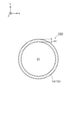
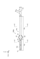
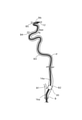
- Explanatory drawing schematically showing the structure of the balloon catheter 100 in 1st Embodiment Explanatory drawing (cross-sectional view) schematically showing the tip shaft portion 14 of the shaft 10. Explanatory drawing (cross-sectional view) schematically showing the base end shaft portion 16 of the shaft 10. Explanatory drawing showing a state in which a balloon catheter 100 is arranged in a blood vessel Explanatory drawing schematically showing the structure of the balloon catheter 100a in the second embodiment. Explanatory drawing (cross-sectional view) schematically showing the base end shaft portion 16a of the shaft 10a. Explanatory drawing showing a state in which a balloon catheter 100a is arranged in a blood vessel Explanatory drawing which shows the recovery state of thrombus piece C by a side hole 20
- FIG. 1 is an explanatory diagram schematically showing the configuration of the balloon catheter 100 in the first embodiment.
- FIG. 2 is an explanatory diagram schematically showing the tip shaft portion 14 of the shaft 10
- FIG. 3 is an explanatory diagram schematically showing the base end shaft portion 16 of the shaft 10.
- FIG. 2 shows a cross section (XY cross section: cross section cut along a plane including the X axis and the Y axis shown in FIG. 1) of the shaft 10 (tip shaft portion 14) at the position II-II in FIG. Figure) shows the configuration.
- FIG. 3 shows the configuration of the cross section of the shaft 10 (base end shaft portion 16) at the position III-III of FIG.
- the balloon 30 and the connector 40 described later are omitted.
- the Z-axis positive direction side (the side of the tip 12 of the balloon catheter 100) is the distal side (distal side) inserted into the body, and the negative Z-axis side (the tip 12 of the balloon catheter 100).
- the side opposite to the side of the balloon is the proximal side (proximal side) operated by a technician such as a doctor.
- FIG. 1 shows a state in which the balloon catheter 100 is in a linear shape parallel to the Z-axis direction as a whole, but the balloon catheter 100 has sufficient flexibility to be curved. Further, FIG. 1 shows a state in which the balloon 30 described later is expanded.
- the balloon catheter 100 is inserted into a blood vessel, for example, to expand the balloon 30 so as to be in close contact with the blood vessel wall on the front side of a lesion (stenosis or occlusion) in the blood vessel to block blood flow.
- a lesion stenosis or occlusion
- Device for. As shown in FIG. 1, the balloon catheter 100 includes a shaft 10 and a balloon 30.
- the shaft 10 is a tubular (for example, cylindrical) member having an open tip and a proximal end.
- "cylindrical shape (cylindrical shape)” is not limited to a perfect cylindrical shape (cylindrical shape), but is substantially cylindrical (substantially cylindrical shape, for example, slightly conical shape or a part) as a whole. It may be a shape with irregularities, etc.).
- a main lumen S1 and an extended lumen S2 are formed inside the shaft 10.
- a linear device such as a guide wire, a recovery device (stent retriever, suction catheter), or a dilator is inserted through the main lumen S1.
- the fluid may be a gas or a liquid, and examples thereof include gases such as helium gas, CO 2 gas, and O 2 gas, and liquids such as physiological saline and contrast media. That is, the balloon catheter 100 is a so-called two-lumen type catheter including a main lumen S1 and an expanded lumen S2.
- the main lumen S1 is an example of the first lumen in the claims
- the extended lumen S2 is an example of the second lumen in the claims.
- the shaft 10 has a tip shaft portion 14 and a base end shaft portion 16.
- the tip shaft portion 14 is an example of a first shaft portion in the claims
- the proximal shaft portion 16 is an example of a second shaft portion in the claims.
- the tip shaft portion 14 is a portion including the tip of the shaft 10.
- the tip shaft portion 14 has a single lumen structure in which only the main lumen S1 is formed.
- the main lumen S1 penetrates the entire length of the tip shaft portion 14 in the axial direction.
- the main lumen S1 is formed at a substantially central portion of the distal shaft portion 14.
- the thickness D1 of the tip shaft portion 14 is substantially the same over the entire circumference.
- both the outer peripheral shape and the inner peripheral shape of the tip shaft portion 14 are substantially circular when viewed from the axial direction.
- the axial length of the tip shaft portion 14 is, for example, 2 cm.
- a tip tip 12 is provided at the tip of the tip shaft portion 14.
- the tip tip 12 is a cylindrical member having an open tip and a rear end.
- the tip tip 12 may have an outer shape having the same outer diameter over the entire length, or may have a tapered outer diameter in which the outer diameter gradually decreases toward the tip.
- the device inserted in the main lumen S1 is led out from the tip of the tip tip 12.
- the tip tip 12 has a flexibility equal to or higher than that of the base end side of the tip shaft portion 14.
- the base end shaft portion 16 is a portion including the base end of the shaft 10.
- the tip shaft portion 14 and the proximal shaft portion 16 are adjacent to each other in the axial direction.
- the base end shaft portion 16 has a double lumen structure in which an extended lumen S2 is formed in addition to the main lumen S1.
- the main lumen S1 penetrates over the entire length of the proximal shaft portion 16 in the axial direction.
- the extended lumen S2 extends from the proximal end of the proximal shaft portion 16 toward the distal end side, and is open to the outer peripheral surface of the distal end portion of the proximal shaft portion 16. Specifically, as shown in FIG.
- the main lumen S1 is formed at a slightly eccentric position in the proximal shaft portion 16 when viewed from the axial direction, and the extended lumen S2 is the outer periphery of the main lumen S1. It is formed on the side. The diameter of the extended lumen S2 is smaller than the diameter of the main lumen S1.
- the diameter of the main lumen S1 formed on the tip shaft portion 14 and the diameter of the main lumen S1 formed on the proximal shaft portion 16 are substantially the same.
- the fact that A and B are substantially the same means that the error between A and B is 5% or less of A or B. That is, a main lumen S1 having substantially the same diameter is formed through the shaft 10 over the entire length.
- the thickness D2 of the proximal shaft portion 16 on the side opposite to the extended lumen S2 is substantially the same as the thickness D1 of the distal shaft portion 14.
- the thickness D3 of the proximal shaft portion 16 on the side on which the extended lumen S2 is formed is thicker than the thickness D2 on the side opposite to the expanded lumen S2.
- the tip shaft portion 14 has a thinner portion than the proximal shaft portion 16, and the outer diameter of the tip shaft portion 14 is smaller than the outer diameter of the proximal shaft portion 16.
- the flexibility of the tip shaft portion 14 is higher than the flexibility of the base end shaft portion 16.
- the shore hardness of the outer layer resin material of the tip shaft portion 14 is D47 or less.
- the shore hardness of the outer layer resin material of the tip shaft portion 14 may be D40 or less.
- a connector 40 for introducing a device, a fluid, or the like is attached to each lumen S1 and S2 at the base end of the base end shaft portion 16.
- the shaft 10 is integrally formed of the same material throughout.
- the shaft 10 is preferably made of a material that can be heat-sealed and has a certain degree of flexibility.
- the material for forming the shaft 10 include a thermoplastic resin, more specifically polyethylene, polypropylene, polybutene, an ethylene-propylene copolymer, an ethylene-vinyl acetate copolymer, an ionomer, or a mixture of two or more thereof.
- examples thereof include polyolefins such as, polyvinyl chloride resin, polyamide, nylon, polyamide elastomer, polyester, polyester elastomer, thermoplastic polyurethane and the like.
- a hydrophilic coating 18 formed of a hydrophilic resin is formed on the tip portion of the outer peripheral surface of the tip shaft portion 14 of the shaft 10 over the entire circumference of the tip shaft portion 14.
- the hydrophilic coating 18 is provided to reduce the frictional resistance between the surface of the tip shaft portion 14 and the inner wall of the blood vessel to ensure slipperiness when the tip shaft portion 14 is inserted into the blood vessel. ..
- the hydrophilic coating 18 is not formed on the base end side of the tip shaft portion 14, and the friction coefficient of the outer peripheral surface is higher than that of the tip portion.
- the balloon 30 is an expansion part that can be expanded and contracted with the supply and discharge of the fluid.
- the balloon 30 covers the outer circumference of the tip portion of the proximal shaft portion 16.
- the front end portion 32 and the rear end portion 34 of the balloon 30 are joined to the outer peripheral surface of the front end portion of the base end shaft portion 16 by, for example, welding.
- the tip portion 32 of the balloon 30 is joined to the outer peripheral surface of the tip of the base end shaft portion 16, and the joint portion between the tip end portion 32 and the base end shaft portion 16 is the tip end in the axial direction. It is adjacent to the shaft portion 14.
- the expansion lumen S2 described above communicates with an internal space S3 (see FIG. 1) formed between the balloon 30 and the proximal shaft portion 16.
- the length of the balloon 30 in the axial direction is, for example, about 2 cm.
- the balloon 30 is preferably made of a material having a certain degree of flexibility, and more preferably made of a material that is thinner than the shaft 10 and has flexibility.
- the material for forming the balloon 30 include polyolefins such as polyethylene, polypropylene, polybutene, ethylene-propylene copolymer, ethylene-vinyl acetate copolymer, ionomer, or a mixture of two or more thereof, and a soft polyvinyl chloride resin.
- FIG. 4 is an explanatory diagram showing a state in which the balloon catheter 100 is arranged in a blood vessel.
- the vessels on the far side of the carotid artery (common carotid artery B, external carotid artery B1, internal carotid artery cervical part B2, internal carotid artery pyramidal part B3, ocular artery B4, anterior cerebral artery B5, middle cerebral artery).
- B6 is schematically shown.
- the balloon catheter 100 is a guiding catheter with a balloon, and is used, for example, for thrombus recovery treatment in acute cerebral infarction.
- the balloon catheter 100 is inserted into the blood vessel and pushed from the common carotid artery B into, for example, the internal carotid artery neck B2.
- Petras P which is a flexion blood vessel, is present in the neck B2 of the internal carotid artery.
- the proximal shaft portion 16 of the shaft 10 has relatively low flexibility (high rigidity), and particularly the flexibility of the joint portion between the balloon 30 and the proximal shaft portion 16 is low. Therefore, it is difficult to insert the base end shaft portion 16 into the petras P.
- the tip shaft portion 14 of the shaft 10 has relatively high flexibility, and the axial length of the tip shaft portion 14 is 1.5 cm or more. Therefore, as shown in FIG. 4, the tip shaft portion 14 can be relatively easily inserted into the petras P.
- the balloon 30 By expanding the balloon 30 with the tip shaft portion 14 inserted into the petras P, the blood flow in the carotid artery is temporarily blocked. At this time, the balloon 30 is located, for example, in front of Petras P in the internal carotid artery neck B2.
- a recovery device (not shown) is led out from the tip of the balloon catheter 100 via the main lumen S1 and sent out to the vicinity of the lesion existing beyond the petras P (for example, the internal carotid artery pyramidal portion B3 or the like). Then, the thrombus fragment is captured by using the recovery device, and the recovery device that has captured the thrombus fragment is drawn into the main lumen S1 of the balloon catheter 100. This makes it possible to collect the thrombus fragments in the blood vessels.
- the tip shaft portion 14 having relatively high flexibility is arranged on the tip side of the balloon 30 (see FIGS. 1 and 2).
- the distance between the tip of the balloon catheter 100 and the lesion portion in the blood vessel (hereinafter referred to as “thrombus recovery distance”) is shorter than that in the configuration without the tip shaft portion 14.
- the thrombus recovery distance is shortened, for example, damage to the blood vessel caused by the recovery device can be suppressed by the amount that the distance traveled in the blood vessel in the exposed state of the recovery device is shortened. For example, it is possible to reduce the risk of blood vessel perforation or spasm due to the recovery device scratching the blood vessel.
- the tip shaft portion 14 bends in the petras P, so that the position of the tip shaft portion 14 in the blood vessel is fixed and the support force of the balloon catheter 100 is improved. That is, in general, it is preferable to reduce the flexibility of the shaft in order to improve the support force, but on the other hand, the flexibility is reduced, so that the insertability into the blood vessel (blood vessel followability) is lowered.
- the tip shaft portion 14 having flexibility in the petras P is arranged on the tip side of the balloon 30. Therefore, it is possible to improve the support force of the balloon catheter 100 by bending the tip shaft portion 14 while ensuring the blood vessel followability of the tip shaft portion 14.
- a hydrophilic coating 18 having a relatively low coefficient of friction is formed on the tip portion of the tip shaft portion 14. Therefore, the tip end side of the tip shaft portion 14 can be smoothly inserted into the petras P. Further, the hydrophilic coating 18 is not formed on the base end side of the tip shaft portion 14, and the friction coefficient is relatively high. Therefore, the position of the tip shaft portion 14 in the blood vessel is more firmly fixed by the proximal end side coming into contact with the inner wall surface of the petras P while the tip shaft portion 14 is bent. This makes it possible to further improve the support force of the balloon catheter 100.
- FIG. 5 is an explanatory diagram schematically showing the configuration of the balloon catheter 100a in the second embodiment.
- FIG. 6 is an explanatory diagram schematically showing a base end shaft portion 16a of the shaft 10a.
- FIG. 6 shows the configuration of the cross section of the shaft 10a (base end shaft portion 16a) at the position of VI-VI in FIG. In FIG. 6, the balloon 30 and the connector 40 are omitted.
- the configuration of the cross section of the shaft 10a (tip shaft portion 14a) at the position II-II in FIG. 6 is the same as that in FIG. 2 of the first embodiment.
- the same configurations as those of the balloon catheter 100 of the first embodiment described above will be appropriately described by adding the same reference numerals.
- the shaft 10a included in the balloon catheter 100a is a tubular (for example, cylindrical) member having an open tip and proximal end. As shown in FIGS. 2 and 6, a main lumen S1 and an extended lumen S2a are formed inside the shaft 10a.
- the extended lumen S2a is an example of a second lumen in the claims.
- the shaft 10a has a tip shaft portion 14a and a proximal shaft portion 16a.
- the tip shaft portion 14a is an example of a first shaft portion in the claims
- the proximal shaft portion 16a is an example of a second shaft portion in the claims.
- the tip shaft portion 14a has a single lumen structure in which only the main lumen S1 is formed, similar to the tip shaft portion 14 of the first embodiment (see FIG. 2). However, the axial length of the tip shaft portion 14a is longer than the axial length of the tip shaft portion 14 of the first embodiment, for example, 20 cm. Further, a side hole 20 communicating with the main lumen S1 is formed on the outer peripheral surface of the tip shaft portion 14a on the base end side. In the present embodiment, the pair of side holes 20 are arranged at positions symmetrical with respect to the central axis of the tip shaft portion 14a (see FIG. 8 described later).
- the base end shaft portion 16a has a coaxial structure in which an extended lumen S2a is formed in addition to the main lumen S1.
- the extended lumen S2a extends from the proximal end of the proximal shaft portion 16a toward the distal end side, and is open to the outer peripheral surface of the distal end portion of the proximal end shaft portion 16.
- the main lumen S1 is formed in the central portion of the proximal shaft portion 16a
- the extended lumen S2a surrounds the outer periphery of the main lumen S1. It is formed in a ring shape.
- the diameter of the main lumen S1 formed in the tip shaft portion 14a and the diameter of the main lumen S1 formed in the proximal shaft portion 16a are substantially the same. That is, a main lumen S1 having substantially the same diameter is formed through the shaft 10a over the entire length.
- the thickness D1 of the tip shaft portion 14a is thinner than the thickness D4 of the base end shaft portion 16a, and the outer diameter of the tip end shaft portion 14a is smaller than the outer diameter of the base end shaft portion 16a.
- the flexibility of the tip shaft portion 14a is higher than the flexibility of the proximal shaft portion 16a.
- the shore hardness of the outer layer resin material of the tip shaft portion 14a is D47 or less.
- the shore hardness of the outer layer resin material of the tip shaft portion 14 may be D40 or less.
- a hydrophilic coating 18a formed of a hydrophilic resin is formed on the entire outer peripheral surface of the tip shaft portion 14a of the shaft 10a.
- FIG. 7 is an explanatory diagram showing a state in which the balloon catheter 100a is arranged in the blood vessel.
- the balloon 30 is located near the entrance of the internal carotid artery neck B2, and the tip shaft portion 14a extends beyond Petras P to the vicinity of the middle cerebral artery B6.
- the tip of the balloon catheter 100a can be brought close to the vicinity of the lesion located further away from Petras P.
- FIG. 8 is an explanatory diagram showing a state in which the thrombus piece C is collected by the side hole 20.
- the tip shaft portion 14a protrudes toward the tip side of the balloon 30. Therefore, for example, when collecting the thrombus piece C from the lesion portion, the thrombus piece C is not collected in the opening of the main lumen S1 formed at the tip of the tip shaft portion 14a, and is not collected in the opening of the tip shaft portion 14a on the outer peripheral side. It may get in (see FIGS. 8 (a) and 8 (b)). However, according to the present embodiment, the uncollected thrombus piece C is recovered in the main lumen S1 via the side hole 20 formed in the tip shaft portion 14a.
- the axial length of the tip shaft portions 14, 14a in each of the above embodiments may be any length of 1.5 cm or more.
- the axial length of the tip shaft portion 14 may be 1.5 cm or more and less than 2 cm, or may be longer than 2 cm.
- the axial length of the tip shaft portion 14a may be 1.5 cm or more, less than 20 cm, or longer than 20 cm.
- the tip shaft portions 14, 14a may be configured not to include the tip tip 12.
- the main lumen S1 and the extended lumens S2, S2a do not extend to the proximal end of the proximal shaft portions 16, 16a (shafts 10, 10a), but bend in the middle and open to the outer peripheral surface of the shaft 10. It may be the same configuration.
- the extended lumens S2 and S2a may be configured to extend to the tip shaft portions 14, 14a.
- the number of lumens formed on the tip shaft portions 14, 14a may be two or more, and the number of lumens formed on the proximal shaft portions 16, 16a may be three or more.
- the first shaft portion is more flexible (that is, has lower flexural rigidity) than the second shaft portion.
- the first shaft portion is more flexible (that is, has lower flexural rigidity) than the second shaft portion.
- the shaft may have a configuration in which the first shaft portion is formed of a material having a hardness lower than that of the material for forming the second shaft portion.
- the tip portion 32 of the balloon 30 may be configured to be slightly joined to the proximal end side from the distal end portions of the proximal end shaft portions 16, 16a. That is, the balloon 30 may be configured to be joined to the distal end side of the proximal shaft portions 16, 16a.
- the balloon catheter in the claims may have a configuration in which a first shaft portion having relatively high flexibility is provided on the distal end side of the second shaft portion to which the balloon is joined.
- the balloon catheters 100 and 100a may not be provided with the hydrophilic coatings 18 and 18a.
- the side hole may be formed on the outer peripheral surface of the tip shaft portion 14, or in the second embodiment, the side hole is not formed on the outer peripheral surface of the tip shaft portion 14a. It may be configured.
- the outer diameters of the shafts 10 and 10a may be substantially the same over the entire length.
- the shape of the cross section of the shafts 10 and 10a is not limited to a circle, but may be a polygonal shape or the like.
- the entire shaft 10, 10a, the tip shaft portions 14, 14a, or the base end shaft portions 16, 16a is not limited to a single layer configuration, and may be configured to include a plurality of resin layers (for example, an inner layer resin and an outer layer resin). Further, a reinforcing body (blade), a coil body, or the like may be embedded.
- the tip shaft portions 14, 14a and the proximal end shaft portions 16, 16a are the same for each of the plurality of resin layers and reinforcing bodies. It may be integrally formed of materials.
- each member in the above embodiment is merely an example and can be variously deformed.
- the balloon catheters 100 and 100a inserted into the blood vessel are exemplified as the balloon catheter, but the balloon catheter may be inserted into a body cavity other than the blood vessel (for example, the esophagus).
Landscapes
- Health & Medical Sciences (AREA)
- Life Sciences & Earth Sciences (AREA)
- Heart & Thoracic Surgery (AREA)
- Anesthesiology (AREA)
- Biophysics (AREA)
- Pulmonology (AREA)
- Engineering & Computer Science (AREA)
- Biomedical Technology (AREA)
- Hematology (AREA)
- Animal Behavior & Ethology (AREA)
- General Health & Medical Sciences (AREA)
- Public Health (AREA)
- Veterinary Medicine (AREA)
- Child & Adolescent Psychology (AREA)
- Vascular Medicine (AREA)
- Media Introduction/Drainage Providing Device (AREA)
Abstract
バルーンカテーテルの先端と病変部との距離の短縮化を図る。 バルーンカテーテルは、第1のシャフト部分と、第1のシャフト部分より基端側に位置する第2のシャフト部分と、を有するシャフトと、第2のシャフト部分を覆うとともに第2のシャフト部分に接合されたバルーンと、を備える。第1のシャフト部分の柔軟性は、第2のシャフト部分の柔軟性よりも高く、かつ、第1のシャフト部分の軸方向の長さは1.5cm以上である。
Description
本明細書に開示される技術は、バルーンカテーテルに関する。
血管等の体腔内に挿入して拡張・収縮させるバルーンを備えるバルーンカテーテルが知られている。バルーンカテーテルは、シャフトと、そのシャフトの一部を覆うとともにシャフトに接合されたバルーンとを備える(例えば、下記特許文献1参照)。このバルーンカテーテルでは、シャフトのうち、バルーンが接合された部分(以下、「バルーン接合部分」という)と、そのバルーンより先端側の部分(以下、「カテーテル先端部分」という)とは、互いに同一の柔軟性を有する。
上述した従来のバルーンカテーテルでは、カテーテル先端部分は、バルーン接合部分と同程度の柔軟性しか有していない。このため、バルーンカテーテルを、例えば血管内の曲がった部分に挿入する場合、その曲がった部分にカテーテル先端部分を挿入することが困難であり、その結果、バルーンカテーテルの先端を、血管内における病変部(例えば狭窄部や閉塞部)に近づけることができない。このような場合、例えばバルーンカテーテルを用いて病変部に対する適切な処置を施すことができなくなる。
本明細書では、上述した課題を解決することが可能な技術を開示する。
本明細書に開示される技術は、例えば、以下の形態として実現することが可能である。
(1)本明細書に開示されるバルーンカテーテルは、バルーンカテーテルであって、第1のシャフト部分と、前記第1のシャフト部分より基端側に位置する第2のシャフト部分と、を有するシャフトと、前記第2のシャフト部分を覆うとともに前記第2のシャフト部分に接合されたバルーンと、を備え、前記第1のシャフト部分の柔軟性は、前記第2のシャフト部分の柔軟性よりも高く、かつ、前記第1のシャフト部分の軸方向の長さは1.5cm以上である。本バルーンカテーテルでは、シャフトは、バルーンが接合された第2のシャフト部分より先端側に第1のシャフト部分を備えている。この第1のシャフト部分の柔軟性は、第2のシャフト部分の柔軟性よりも低く、かつ、第1のシャフト部分の軸方向の長さは1.5cm以上である。このため、本バルーンカテーテルによれば、例えば第1のシャフト部分を備えない構成に比べて、バルーンカテーテル(第1のシャフト部分)の先端を病変部の近くまで挿入し易いため、バルーンカテーテルの先端と病変部との距離の短縮化を図ることができる。
(2)上記バルーンカテーテルにおいて、前記第1のシャフト部分の外層と、前記第2のシャフト部分の外層は、それぞれ樹脂で構成されており、前記第1のシャフト部分の外層の樹脂材料はショア硬さがD47以下である構成としてもよい。本バルーンカテーテルによれば、第1のシャフト部分の外層の樹脂材料のショア硬さがD47より高い構成に比べて、バルーンカテーテルの先端を病変部の近くまでさらに挿入し易いため、バルーンカテーテルの先端と病変部との距離のさらなる短縮化を図ることができる。
(3)上記バルーンカテーテルにおいて、前記第1のシャフト部分の外層と、前記第2のシャフト部分の外層は、それぞれ樹脂で構成されており、前記第1のシャフト部分の外層の樹脂材料はショア硬さがD40以下である構成としてもよい。本バルーンカテーテルによれば、第1のシャフト部分の外層の樹脂材料のショア硬さがD40より高い構成に比べて、バルーンカテーテルの先端を病変部の近くまでさらに挿入し易いため、バルーンカテーテルの先端と病変部との距離のさらなる短縮化を図ることができる。
(4)上記バルーンカテーテルにおいて、前記シャフトには、前記第2のシャフト部分の基端側から前記第1のシャフト部分の先端まで貫通する第1のルーメンが形成されており、前記第1のシャフト部分の基端側の外周面には、前記第1のルーメンに連通するサイドホールが形成されている構成としてもよい。本バルーンカテーテルでは、第1のシャフト部分がバルーンよりも先端側に突出している。このため、例えば病変部からの回収物(例えば血栓片等)を回収する場合、回収物が、第1のシャフト部分の先端に形成された第1のルーメンの開口内に回収されずに、第1のシャフト部分の外周側に入り込む可能性がある。しかし、本バルーンカテーテルによれば、その回収されなかった回収物を、サイドホールを介して回収することができる。
(5)上記バルーンカテーテルにおいて、前記第1のシャフト部分のうち、少なくとも先端側の外周面には、親水性コーティングが形成されている構成としてもよい。本バルーンカテーテルによれば、親水性コーティングによって第1のシャフト部分の滑りやすさが向上するため、体腔内への第1のシャフト部分の挿入性を向上させることができる。
(6)上記バルーンカテーテルにおいて、前記親水性コーティングは、前記第1のシャフト部分の先端部分の外周面に形成されており、前記第1のシャフト部分のうち、前記親水性コーティングより基端側の外周面の摩擦係数は、前記親水性コーティングの摩擦係数よりも高い構成としてもよい。本バルーンカテーテルによれば、第1のシャフト部分の先端部分は、相対的に摩擦係数が高い親水性コーティングが形成されているため、第1のシャフト部分の先端側を容易に体腔内に挿入させることができる。また、第1のシャフト部分のうち、親水性コーティングより基端側の外周面の摩擦係数は、親水性コーティングの摩擦係数よりも低い。このため、第1のシャフト部分のうち、相対的に摩擦係数が高い基端側は、例えば屈曲した体腔内の内壁面との接触により相対的な移動が規制される。これにより、バルーンカテーテルの第1のシャフト部分を体腔内に挿入させつつ、その挿入させた状態の保持性を向上させることができる。
(7)上記バルーンカテーテルにおいて、前記第1のシャフト部分と前記第2のシャフト部分とが一体形成されており、前記シャフトには、前記第2のシャフト部分の基端側から前記第1のシャフト部分の先端まで貫通する第1のルーメンと、前記第2のシャフト部分の基端側から前記バルーン内まで伸びるとともに前記バルーン内に連通している第2のルーメンと、が形成されており、前記第1のシャフト部分の外径は、前記第2のシャフト部分の外径より小さい構成としてもよい。シャフトが一体形成されており、第1のシャフト部分には第2のルーメン(拡張ルーメン)が形成されておらず、かつ、第1のシャフト部分は第2のシャフト部分より径小である。(効果)本バルーンカテーテルでは、第1のシャフト部分と第2のシャフト部分とが一体形成されているため、第1のシャフト部分と第2のシャフト部分と互いに別体で接合された構成に比べて、シャフトのトルク伝達性が高い。また、ルーメンの数の相違と外径の相違とによって第1のシャフト部分と第2のシャフト部分との柔軟性の差が実現されている。すなわち、本バルーンカテーテルによれば、シャフトのトルク伝達性の低下を抑制しつつ、バルーンカテーテルの先端と病変部との距離の短縮化を図ることができる。
A.第1実施形態:
A-1.バルーンカテーテル100の基本構成:
図1は、第1実施形態におけるバルーンカテーテル100の構成を概略的に示す説明図である。図2は、シャフト10の先端シャフト部分14を概略的に示す説明図であり、図3は、シャフト10の基端シャフト部分16を概略的に示す説明図である。図2には、図1のII-IIの位置におけるシャフト10(先端シャフト部分14)の横断面(XY断面:図1に記載されたX軸とY軸とを含む平面に沿って切断した断面図)の構成が示されている。図3には、図1のIII-IIIの位置におけるシャフト10(基端シャフト部分16)の横断面の構成が示されている。なお、図2および図3では、後述のバルーン30やコネクタ40は省略されている。
A-1.バルーンカテーテル100の基本構成:
図1は、第1実施形態におけるバルーンカテーテル100の構成を概略的に示す説明図である。図2は、シャフト10の先端シャフト部分14を概略的に示す説明図であり、図3は、シャフト10の基端シャフト部分16を概略的に示す説明図である。図2には、図1のII-IIの位置におけるシャフト10(先端シャフト部分14)の横断面(XY断面:図1に記載されたX軸とY軸とを含む平面に沿って切断した断面図)の構成が示されている。図3には、図1のIII-IIIの位置におけるシャフト10(基端シャフト部分16)の横断面の構成が示されている。なお、図2および図3では、後述のバルーン30やコネクタ40は省略されている。
図1において、Z軸正方向側(バルーンカテーテル100の先端チップ12の側)が、体内に挿入される先端側(遠位側)であり、Z軸負方向側(バルーンカテーテル100の先端チップ12の側とは逆側)が、医師等の手技者によって操作される基端側(近位側)である。なお、図1では、バルーンカテーテル100が全体としてZ軸方向に平行な直線状となった状態を示しているが、バルーンカテーテル100は湾曲させることができる程度の柔軟性を有している。また、図1では、後述のバルーン30が拡張した状態が示されている。
バルーンカテーテル100は、例えば血管内における病変部(狭窄部や閉塞部)の手前側において血管壁に密着するようにバルーン30を拡張させて血流を遮断するために、血管内に挿入される医療用デバイスである。図1に示すように、バルーンカテーテル100は、シャフト10と、バルーン30とを備えている。
シャフト10は、先端と基端とが開口した筒状(例えば円筒状)の部材である。なお、本明細書において「筒状(円筒状)」とは、完全な筒形状(円筒形状)に限らず、全体として略筒状(略円筒形状、例えば、若干、円錐形状や、一部に凹凸がある形状など)でもよい。図2および図3に示すように、シャフト10の内部には、メインルーメンS1と拡張ルーメンS2とが形成されている。メインルーメンS1には、ガイドワイヤ、回収デバイス(ステントリトリーバー、吸引カテーテル)やダイレータ等の線状のデバイス(図示しない)が挿通される。拡張ルーメンS2には、バルーン30を拡張するための拡張用の流体が流通する。なお、流体は、気体でも液体でもよく、例えば、ヘリウムガス、CO2ガス、O2ガス等の気体や、生理食塩水、造影剤等の液体が挙げられる。すなわち、バルーンカテーテル100は、メインルーメンS1と拡張ルーメンS2とを備える、いわゆる2ルーメンタイプのカテーテルである。メインルーメンS1は、特許請求の範囲における第1のルーメンの一例であり、拡張ルーメンS2は、特許請求の範囲における第2のルーメンの一例である。
具体的には、シャフト10は、先端シャフト部分14と基端シャフト部分16とを有する。先端シャフト部分14は、特許請求の範囲における第1のシャフト部分の一例であり、基端シャフト部分16は、特許請求の範囲における第2のシャフト部分の一例である。
先端シャフト部分14は、シャフト10の先端を含む部分である。先端シャフト部分14は、メインルーメンS1のみが形成されたシングルルーメン構造である。メインルーメンS1は、先端シャフト部分14の軸方向の全長にわたって貫通している。図2に示すように、バルーンカテーテル100の軸方向(各図ではZ軸方向)から見たとき、メインルーメンS1は、先端シャフト部分14における略中央部に形成されている。軸方向から見たとき、先端シャフト部分14の厚さD1は、全周にわたって略同一である。なお、本実施形態では、軸方向から見たとき、先端シャフト部分14の外周形状と内周形状とはいずれも略円形である。先端シャフト部分14の軸方向の長さは、例えば2cmである。
なお、先端シャフト部分14の先端には、先端チップ12が設けられている。先端チップ12は、先端と後端とが開口した筒状の部材である。先端チップ12は、全長にわたって外径が同一の外形でもよいし、先端に向かって外径が徐々に小さくなるテーパ状の外形でもよい。メインルーメンS1に挿入されたデバイスは、先端チップ12の先端から外部に導出される。先端チップ12は、先端シャフト部分14の基端側と同等以上の柔軟性を有している。
基端シャフト部分16は、シャフト10の基端を含む部分である。先端シャフト部分14と基端シャフト部分16とは、軸方向において互いに隣接している。基端シャフト部分16は、メインルーメンS1に加えて拡張ルーメンS2が形成されたダブルルーメン構造である。メインルーメンS1は、基端シャフト部分16の軸方向の全長にわたって貫通している。拡張ルーメンS2は、基端シャフト部分16の基端から先端側に向かって伸びており、基端シャフト部分16の先端部分の外周面に開口している。具体的には、図3に示すように、軸方向から見たとき、メインルーメンS1は、基端シャフト部分16における若干偏心した位置に形成されており、拡張ルーメンS2は、メインルーメンS1の外周側に形成されている。拡張ルーメンS2の径は、メインルーメンS1の径よりも小さい。
先端シャフト部分14に形成されたメインルーメンS1の径と基端シャフト部分16に形成されたメインルーメンS1の径とは略同一である。なお、本明細書において、AとBとが略同一とは、AとBとの誤差がAまたはBの5%以下であることを意味する。すなわち、シャフト10には、全長にわたって略同一径のメインルーメンS1が貫通形成されている。軸方向から見て、基端シャフト部分16のうち、拡張ルーメンS2とは反対側の厚さD2は、先端シャフト部分14の厚さD1と略同一である。基端シャフト部分16のうち、拡張ルーメンS2が形成された側の厚さD3は、拡張ルーメンS2とは反対側の厚さD2に比べて厚い。このように、先端シャフト部分14は、基端シャフト部分16に比べて肉薄の部分を有し、かつ、先端シャフト部分14の外径は、基端シャフト部分16の外径より小さい。これにより、先端シャフト部分14の柔軟性は、基端シャフト部分16の柔軟性よりも高くなっている。例えば先端シャフト部分14の外層樹脂材料のショア硬さがD47以下である。先端シャフト部分14の外層樹脂材料のショア硬さがD40以下でもよい。なお、基端シャフト部分16の基端には、各ルーメンS1,S2にデバイスや流体等を導入するためのコネクタ40が取り付けられている。
本実施形態では、シャフト10は、全体にわたって同一の材料により一体形成されている。シャフト10は、熱融着可能であり、かつ、ある程度の可撓性を有する材料により形成されていることが好ましい。シャフト10の形成材料としては、例えば、熱可塑性樹脂、より具体的には、ポリエチレン、ポリプロピレン、ポリブテン、エチレン-プロピレン共重合体、エチレン-酢酸ビニル共重合体、アイオノマー、あるいはこれら二種以上の混合物等のポリオレフィンや、ポリ塩化ビニル樹脂、ポリアミド、ナイロン、ポリアミドエラストマー、ポリエステル、ポリエステルエラストマー、熱可塑性ポリウレタン等が挙げられる。
図1に示すように、シャフト10の先端シャフト部分14の外周面の先端部分には、親水性の樹脂により形成された親水性コーティング18が先端シャフト部分14の全周にわたって形成されている。親水性コーティング18は、先端シャフト部分14を血管内に挿入したときに、先端シャフト部分14の表面と血管内壁との間の摩擦抵抗を低減して、滑り性を確保するために設けられている。なお、本実施形態では、先端シャフト部分14における基端側には、親水性コーティング18が形成されておらず、先端部分に比べて外周面の摩擦係数が高くなっている。
バルーン30は、流体の供給および排出に伴い拡張および収縮可能な拡張部である。バルーン30は、基端シャフト部分16の先端部分の外周を覆う。バルーン30の先端部32と後端部34とは、それぞれ、例えば溶着により、基端シャフト部分16の先端部分の外周面に接合されている。なお、本実施形態では、バルーン30の先端部32は、基端シャフト部分16の先端の外周面に接合されており、先端部32と基端シャフト部分16との接合部分は、軸方向において先端シャフト部分14と隣接している。上述した拡張ルーメンS2は、バルーン30と基端シャフト部分16との間に形成される内部空間S3(図1参照)に連通している。バルーン30は、収縮された状態では、基端シャフト部分16の外周面に密着するように折り畳まれる(図示しない)。なお、バルーン30の軸方向の長さは、例えば2cm程度である。
バルーン30は、ある程度の可撓性を有する材料により形成されていることが好ましく、シャフト10より薄くて、可撓性を有する材料により形成されていることがより好ましい。バルーン30の形成材料としては、例えば、ポリエチレン、ポリプロピレン、ポリブテン、エチレン-プロピレン共重合体、エチレン-酢酸ビニル共重合体、アイオノマー、あるいはこれら二種以上の混合物等のポリオレフィンや、軟質ポリ塩化ビニル樹脂、ポリアミド、ポリアミドエラストマー、ポリエステル、ポリエステルエラストマー、ポリウレタン、フッ素樹脂等の熱可塑性樹脂、シリコーンゴム、ラテックスゴム等が挙げられる。
A-2.バルーンカテーテル100の使用例:
次に、第1実施形態におけるバルーンカテーテル100の使用例について説明する。図4は、バルーンカテーテル100を血管内に配置した状態を示す説明図である。図4には、頸動脈の以遠側の血管(総頸動脈B、外頸動脈B1、内頸動脈頸部B2、内頸動脈錐体部B3、眼動脈B4、前大脳動脈B5、中大脳動脈B6)が模式的に示されている。バルーンカテーテル100は、バルーン付きガイディングカテーテルであり、例えば、急性期脳梗塞における血栓回収治療に用いられる。
次に、第1実施形態におけるバルーンカテーテル100の使用例について説明する。図4は、バルーンカテーテル100を血管内に配置した状態を示す説明図である。図4には、頸動脈の以遠側の血管(総頸動脈B、外頸動脈B1、内頸動脈頸部B2、内頸動脈錐体部B3、眼動脈B4、前大脳動脈B5、中大脳動脈B6)が模式的に示されている。バルーンカテーテル100は、バルーン付きガイディングカテーテルであり、例えば、急性期脳梗塞における血栓回収治療に用いられる。
具体的には、バルーン30が収縮した状態で、バルーンカテーテル100を血管内に挿入し、総頸動脈Bから例えば内頸動脈頸部B2に押し込む。内頸動脈頸部B2には、屈曲血管であるペトラスPが存在している。ここで、シャフト10における基端シャフト部分16は、相対的に柔軟性が低く(剛性が高く)、特にバルーン30と基端シャフト部分16との接合部分の柔軟性が低い。このため、基端シャフト部分16をペトラスPに挿入させることは困難である。
一方、シャフト10における先端シャフト部分14は、相対的に柔軟性が高く、かつ、先端シャフト部分14の軸方向の長さが1.5cm以上である。このため、図4に示すように、先端シャフト部分14を、比較的に容易にペトラスP内に挿入させることができる。先端シャフト部分14がペトラスPに挿入された状態で、バルーン30を拡張させることにより、頸動脈の血流が一時的に遮断される。このとき、バルーン30は、例えば、内頸動脈頸部B2におけるペトラスPの手前に位置している。その後、回収デバイス(図示しない)を、メインルーメンS1を介してバルーンカテーテル100の先端から導出し、ペトラスPの以遠(例えば内頸動脈錐体部B3等)に存在する病変部の近傍まで送り出す。そして、回収デバイスを用いて血栓片を捕捉し、血栓片を捕捉した回収デバイスをバルーンカテーテル100のメインルーメンS1内に引き込む。これにより、血管内の血栓片を回収することができる。
A-3.本実施形態の効果:
以上説明したように、本実施形態のバルーンカテーテル100では、相対的に柔軟性が高い先端シャフト部分14がバルーン30の先端側に配置されている(図1および図2参照)。これにより、本実施形態では、先端シャフト部分14を備えない構成に比べて、血管内におけるバルーンカテーテル100の先端と病変部との距離(以下、「血栓回収距離」という)が短くなる。血栓回収距離が短くなると、例えば、回収デバイスが露出した状態で血管内を移動する距離が短くなる分だけ、回収デバイスによる血管の損傷等を抑制することができる。例えば、回収デバイスが血管を引っ掻くこと等による血管穿孔やスパズムの発生リスクを低減することができる。
以上説明したように、本実施形態のバルーンカテーテル100では、相対的に柔軟性が高い先端シャフト部分14がバルーン30の先端側に配置されている(図1および図2参照)。これにより、本実施形態では、先端シャフト部分14を備えない構成に比べて、血管内におけるバルーンカテーテル100の先端と病変部との距離(以下、「血栓回収距離」という)が短くなる。血栓回収距離が短くなると、例えば、回収デバイスが露出した状態で血管内を移動する距離が短くなる分だけ、回収デバイスによる血管の損傷等を抑制することができる。例えば、回収デバイスが血管を引っ掻くこと等による血管穿孔やスパズムの発生リスクを低減することができる。
また、図4に示すように、先端シャフト部分14がペトラスP内において屈曲することにより、血管内における先端シャフト部分14の位置が固定され、バルーンカテーテル100のサポート力が向上する。すなわち、一般に、サポート力の向上のためには、シャフトの柔軟性を低くすることが好ましいが、その反面、柔軟性が低くなるため、血管内への挿入性(血管追従性)が低下する。これに対して、本実施形態では、ペトラスP内において屈曲可能な柔軟性を有する先端シャフト部分14がバルーン30の先端側に配置されている。このため、先端シャフト部分14による血管追従性を確保しつつ、先端シャフト部分14の屈曲によるバルーンカテーテル100のサポート力の向上を図ることができる。
特に、先端シャフト部分14の先端部分には、相対的に摩擦係数が低い親水性コーティング18が形成されている。このため、先端シャフト部分14の先端側を、ペトラスP内に円滑に挿入させることができる。また、先端シャフト部分14の基端側には、親水性コーティング18が形成されておらず、相対的に摩擦係数が高い。このため、先端シャフト部分14が屈曲しつつその基端側がペトラスPの内壁面に接触することにより、血管内における先端シャフト部分14の位置が、より強固に固定される。これにより、バルーンカテーテル100のサポート力の更なる向上を図ることができる。
B.第2実施形態:
B-1.バルーンカテーテル100aの基本構成:
図5は、第2実施形態におけるバルーンカテーテル100aの構成を概略的に示す説明図である。図6は、シャフト10aの基端シャフト部分16aを概略的に示す説明図である。図6には、図5のVI-VIの位置におけるシャフト10a(基端シャフト部分16a)の横断面の構成が示されている。なお、図6では、バルーン30やコネクタ40は省略されている。また、図6のII-IIの位置におけるシャフト10a(先端シャフト部分14a)の横断面の構成は、上記第1実施形態の図2と同じである。以下では、第2実施形態のバルーンカテーテル100aの構成の内、上述した第1実施形態のバルーンカテーテル100と同一の構成については、同一の符号を付すことによってその説明を適宜省略する。
B-1.バルーンカテーテル100aの基本構成:
図5は、第2実施形態におけるバルーンカテーテル100aの構成を概略的に示す説明図である。図6は、シャフト10aの基端シャフト部分16aを概略的に示す説明図である。図6には、図5のVI-VIの位置におけるシャフト10a(基端シャフト部分16a)の横断面の構成が示されている。なお、図6では、バルーン30やコネクタ40は省略されている。また、図6のII-IIの位置におけるシャフト10a(先端シャフト部分14a)の横断面の構成は、上記第1実施形態の図2と同じである。以下では、第2実施形態のバルーンカテーテル100aの構成の内、上述した第1実施形態のバルーンカテーテル100と同一の構成については、同一の符号を付すことによってその説明を適宜省略する。
バルーンカテーテル100aが備えるシャフト10aは、先端と基端とが開口した筒状(例えば円筒状)の部材である。図2および図6に示すように、シャフト10aの内部には、メインルーメンS1と拡張ルーメンS2aとが形成されている。拡張ルーメンS2aは、特許請求の範囲における第2のルーメンの一例である。
具体的には、シャフト10aは、先端シャフト部分14aと基端シャフト部分16aとを有する。先端シャフト部分14aは、特許請求の範囲における第1のシャフト部分の一例であり、基端シャフト部分16aは、特許請求の範囲における第2のシャフト部分の一例である。
先端シャフト部分14aは、上記第1実施形態の先端シャフト部分14と同様、メインルーメンS1のみが形成されたシングルルーメン構造である(図2参照)。但し、先端シャフト部分14aの軸方向の長さは、上記第1実施形態の先端シャフト部分14の軸方向の長さよりも長く、例えば20cmである。また、先端シャフト部分14aの基端側の外周面には、メインルーメンS1に連通するサイドホール20が形成されている。本実施形態では、一対のサイドホール20が、先端シャフト部分14aの中心軸に対して互いに対称の位置に配置されている(後述の図8参照)。
基端シャフト部分16aは、メインルーメンS1に加えて拡張ルーメンS2aが形成されたコアキシャル構造である。拡張ルーメンS2aは、基端シャフト部分16aの基端から先端側に向かって伸びており、基端シャフト部分16の先端部分の外周面に開口している。具体的には、図6に示すように、軸方向から見たとき、メインルーメンS1は、基端シャフト部分16aにおける中央部に形成されており、拡張ルーメンS2aは、メインルーメンS1の外周を囲むように環状に形成されている。先端シャフト部分14aに形成されたメインルーメンS1の径と基端シャフト部分16aに形成されたメインルーメンS1の径とは略同一である。すなわち、シャフト10aには、全長にわたって略同一径のメインルーメンS1が貫通形成されている。先端シャフト部分14aの厚さD1は、基端シャフト部分16aの厚さD4よりも薄く、かつ、先端シャフト部分14aの外径は、基端シャフト部分16aの外径より小さい。これにより、先端シャフト部分14aの柔軟性は、基端シャフト部分16aの柔軟性よりも高くなっている。例えば先端シャフト部分14aの外層樹脂材料のショア硬さがD47以下である。先端シャフト部分14の外層樹脂材料のショア硬さがD40以下でもよい。
図5に示すように、シャフト10aの先端シャフト部分14aの外周面の全体には、親水性の樹脂により形成された親水性コーティング18aが形成されている。
B-2.バルーンカテーテル100aの使用例:
次に、第2実施形態におけるバルーンカテーテル100aの使用例について説明する。図7は、バルーンカテーテル100aを血管内に配置した状態を示す説明図である。図7に示すように、バルーン30は、内頸動脈頸部B2の入り口付近に位置しており、先端シャフト部分14aは、ペトラスPを超えて中大脳動脈B6付近まで伸びている。このように、先端シャフト部分14aの軸方向の長さが20cm程度である場合、ペトラスPよりもさらに以遠に位置する病変部付近までバルーンカテーテル100aの先端を近づけることができる。
次に、第2実施形態におけるバルーンカテーテル100aの使用例について説明する。図7は、バルーンカテーテル100aを血管内に配置した状態を示す説明図である。図7に示すように、バルーン30は、内頸動脈頸部B2の入り口付近に位置しており、先端シャフト部分14aは、ペトラスPを超えて中大脳動脈B6付近まで伸びている。このように、先端シャフト部分14aの軸方向の長さが20cm程度である場合、ペトラスPよりもさらに以遠に位置する病変部付近までバルーンカテーテル100aの先端を近づけることができる。
図8は、サイドホール20による血栓片Cの回収状態を示す説明図である。バルーンカテーテル100aでは、先端シャフト部分14aがバルーン30よりも先端側に突出している。このため、例えば病変部からの血栓片Cを回収する場合、血栓片Cが、先端シャフト部分14aの先端に形成されたメインルーメンS1の開口内に回収されずに、先端シャフト部分14aの外周側に入り込む可能性がある(図8(a)(b)参照)。しかし、本実施形態によれば、その回収されなかった血栓片Cは、先端シャフト部分14aに形成されたサイドホール20を介してメインルーメンS1内に回収される。
C.変形例:
本明細書で開示される技術は、上述の実施形態に限られるものではなく、その要旨を逸脱しない範囲において種々の形態に変形することができ、例えば次のような変形も可能である。
本明細書で開示される技術は、上述の実施形態に限られるものではなく、その要旨を逸脱しない範囲において種々の形態に変形することができ、例えば次のような変形も可能である。
上記実施形態におけるバルーンカテーテル100,100aの構成は、あくまで一例であり、種々変形可能である。例えば、上記各実施形態における先端シャフト部分14,14aの軸方向の長さは、1.5cm以上の任意の長さでよい。具体的には、上記第1実施形態において、先端シャフト部分14の軸方向の長さは、1.5cm以上、2cm未満でもよいし、2cmより長くてもよい。上記第2実施形態において、先端シャフト部分14aの軸方向の長さは、1.5cm以上、20cm未満でもよいし、20cmより長くてもよい。上記各実施形態において、先端シャフト部分14,14aは、先端チップ12を備えない構成でもよい。
上記各実施形態において、メインルーメンS1および拡張ルーメンS2,S2aは、基端シャフト部分16,16a(シャフト10,10a)の基端まで伸びておらず、途中で曲がってシャフト10の外周面に開口した構成でもよい。また、拡張ルーメンS2,S2aは、先端シャフト部分14,14aまで延伸している構成でもよい。上記実施形態において、先端シャフト部分14,14aに形成されたルーメンの数は2つ以上でもよく、基端シャフト部分16,16aに形成されたルーメンの数は3つ以上でもよい。要するに、第1のシャフト部分と第2のシャフト部分とが同一材料により形成された構成において、第1のシャフト部分を、第2のシャフト部分よりも柔軟性が高い(すなわち、曲げ剛性が低い)横断面の形状とすることにより、特許請求の範囲におけるシャフトを実現できる。例えば、上記実施形態において、第1のシャフト部分に形成されたルーメンの数が第2のシャフト部分に形成されたルーメンの数より少なく、かつ、第1のシャフト部分の外径が第2のシャフト部分の外径より小さい構成である。また、シャフトは、第1のシャフト部分を、第2のシャフト部分の形成材料よりも硬度が低い材料により形成した構成でもよい。
上記実施形態において、バルーン30の先端部32は、基端シャフト部分16,16aの先端部より若干基端側に接合された構成でもよい。すなわち、バルーン30は、基端シャフト部分16,16aの先端側に接合された構成でもよい。要するに、特許請求の範囲におけるバルーンカテーテルは、バルーンが接合された第2のシャフト部分よりも先端側に、相対的に柔軟性が高い第1のシャフト部分を備える構成であればよい。
上記実施形態において、バルーンカテーテル100,100aは、親水性コーティング18,18aを備えない構成でもよい。また、上記第1実施形態において、先端シャフト部分14の外周面にサイドホールが形成された構成でもよいし、上記第2実施形態において、先端シャフト部分14aの外周面にサイドホールが形成されていない構成でもよい。
上記実施形態において、シャフト10,10aの外径が全長にわたって略同一である構成であってもよい。また、シャフト10,10aの横断面の形状は、円形に限らず、多角形状等であってもよい。また、シャフト10,10a全体、先端シャフト部分14,14a、または、基端シャフト部分16,16aは、一層の構成に限らず、複数の樹脂層(例えば内層樹脂と外層樹脂)を備える構成でもよく、更に、補強体(ブレード)やコイル体等が埋設された構成であってもよい。上記実施形態において、シャフト10,10aが複数の樹脂層および補強体を備える場合、複数の樹脂層および補強体のそれぞれについて、先端シャフト部分14,14aと基端シャフト部分16,16aとが互いに同一材料によって一体形成されている構成でもよい。
また、上記実施形態における各部材の材料は、あくまで一例であり、種々変形可能である。
上記実施形態では、バルーンカテーテルとして、血管内に挿入されるバルーンカテーテル100,100aを例示したが、血管以外の体腔(例えば食道等)内に挿入されるものでもよい。
10,10a:シャフト 12:先端チップ 14,14a:先端シャフト部分 16,16a:基端シャフト部分 18,18a:親水性コーティング 20:サイドホール 30:バルーン 32:先端部 34:後端部 40:コネクタ 100,100a:バルーンカテーテル B1:外頸動脈 B2:内頸動脈頸部 B3:内頸動脈錐体部 B4:眼動脈 B5:前大脳動脈 B6:中大脳動脈 B:総頸動脈 C:血栓片 P:ペトラス S1:メインルーメン S2,S2a:拡張ルーメン S3:内部空間
Claims (7)
- バルーンカテーテルであって、
第1のシャフト部分と、前記第1のシャフト部分より基端側に位置する第2のシャフト部分と、を有するシャフトと、
前記第2のシャフト部分を覆うとともに前記第2のシャフト部分に接合されたバルーンと、
を備え、
前記第1のシャフト部分の柔軟性は、前記第2のシャフト部分の柔軟性よりも高く、かつ、前記第1のシャフト部分の軸方向の長さは1.5cm以上である、
バルーンカテーテル。 - 請求項1に記載のバルーンカテーテルであって、
前記第1のシャフト部分の外層と、前記第2のシャフト部分の外層は、それぞれ樹脂で構成されており、
前記第1のシャフト部分の外層の樹脂材料はショア硬さがD47以下である、
バルーンカテーテル。 - 請求項1に記載のバルーンカテーテルであって、
前記第1のシャフト部分の外層と、前記第2のシャフト部分の外層は、それぞれ樹脂で構成されており、
前記第1のシャフト部分の外層の樹脂材料はショア硬さがD40以下である、
バルーンカテーテル。 - 請求項1から請求項3までのいずれか一項に記載のバルーンカテーテルであって、
前記シャフトには、前記第2のシャフト部分の基端側から前記第1のシャフト部分の先端まで貫通する第1のルーメンが形成されており、
前記第1のシャフト部分の基端側の外周面には、前記第1のルーメンに連通するサイドホールが形成されている、
バルーンカテーテル。 - 請求項1から請求項4までのいずれか一項に記載のバルーンカテーテルであって、
前記第1のシャフト部分のうち、少なくとも先端側の外周面には、親水性コーティングが形成されている、
バルーンカテーテル。 - 請求項5に記載のバルーンカテーテルであって、
前記親水性コーティングは、前記第1のシャフト部分の先端部分の外周面に形成されており、
前記第1のシャフト部分のうち、前記親水性コーティングより基端側の外周面の摩擦係数は、前記親水性コーティングの摩擦係数よりも高い、
バルーンカテーテル。 - 請求項1から請求項6までのいずれか一項に記載のバルーンカテーテルであって、
前記第1のシャフト部分と前記第2のシャフト部分とが一体形成されており、
前記シャフトには、前記第2のシャフト部分の基端側から前記第1のシャフト部分の先端まで貫通する第1のルーメンと、前記第2のシャフト部分の基端側から前記バルーン内まで伸びるとともに前記バルーン内に連通している第2のルーメンと、が形成されており、
前記第1のシャフト部分の外径は、前記第2のシャフト部分の外径より小さい、
バルーンカテーテル。
Priority Applications (4)
| Application Number | Priority Date | Filing Date | Title |
|---|---|---|---|
| JP2022539945A JP7408816B2 (ja) | 2020-07-31 | 2020-07-31 | バルーンカテーテル |
| PCT/JP2020/029448 WO2022024348A1 (ja) | 2020-07-31 | 2020-07-31 | バルーンカテーテル |
| US18/158,630 US20230191091A1 (en) | 2020-07-31 | 2023-01-24 | Balloon catheter |
| JP2023214352A JP2024019635A (ja) | 2020-07-31 | 2023-12-20 | バルーンカテーテル |
Applications Claiming Priority (1)
| Application Number | Priority Date | Filing Date | Title |
|---|---|---|---|
| PCT/JP2020/029448 WO2022024348A1 (ja) | 2020-07-31 | 2020-07-31 | バルーンカテーテル |
Related Child Applications (1)
| Application Number | Title | Priority Date | Filing Date |
|---|---|---|---|
| US18/158,630 Continuation US20230191091A1 (en) | 2020-07-31 | 2023-01-24 | Balloon catheter |
Publications (1)
| Publication Number | Publication Date |
|---|---|
| WO2022024348A1 true WO2022024348A1 (ja) | 2022-02-03 |
Family
ID=80035309
Family Applications (1)
| Application Number | Title | Priority Date | Filing Date |
|---|---|---|---|
| PCT/JP2020/029448 Ceased WO2022024348A1 (ja) | 2020-07-31 | 2020-07-31 | バルーンカテーテル |
Country Status (3)
| Country | Link |
|---|---|
| US (1) | US20230191091A1 (ja) |
| JP (2) | JP7408816B2 (ja) |
| WO (1) | WO2022024348A1 (ja) |
Families Citing this family (1)
| Publication number | Priority date | Publication date | Assignee | Title |
|---|---|---|---|---|
| CN119925787A (zh) * | 2023-10-27 | 2025-05-06 | 深圳市纬康医疗科技有限公司 | 一种球囊鞘管 |
Citations (5)
| Publication number | Priority date | Publication date | Assignee | Title |
|---|---|---|---|---|
| JPH07303701A (ja) * | 1994-05-13 | 1995-11-21 | Takashi Nishimura | 造影剤回収用バルーンカテーテル |
| JP2007501652A (ja) * | 2003-08-08 | 2007-02-01 | ボストン サイエンティフィック リミテッド | 伸縮規制用カテーテルシャフト |
| JP2010167003A (ja) * | 2009-01-21 | 2010-08-05 | Asahi Intecc Co Ltd | バルーンカテーテル |
| JP2014138864A (ja) * | 2007-08-06 | 2014-07-31 | Abbott Cardiovascular Systems Inc | インターロッキング・ネットワークに包含される親水性化合物を有する潤滑コーティングを施された医療装置 |
| JP2020500065A (ja) * | 2016-11-23 | 2020-01-09 | イノベーションズ イン メディスン,エルエルシー | 体管腔の偏向のためのシステムおよび方法 |
Family Cites Families (5)
| Publication number | Priority date | Publication date | Assignee | Title |
|---|---|---|---|---|
| US20060074396A1 (en) * | 2004-09-28 | 2006-04-06 | Medtronic Vascular, Inc. | Stent delivery system |
| JP5732259B2 (ja) * | 2011-01-12 | 2015-06-10 | 株式会社グッドマン | カテーテル |
| WO2012162661A1 (en) * | 2011-05-26 | 2012-11-29 | Abbott Cardiovascular Systems Inc. | Through tip for a catheter |
| JP2020039376A (ja) * | 2017-01-23 | 2020-03-19 | テルモ株式会社 | バルーンカテーテル |
| US11642500B2 (en) * | 2018-02-20 | 2023-05-09 | Crossliner, Inc. | Intravascular delivery system and method for percutaneous coronary intervention |
-
2020
- 2020-07-31 JP JP2022539945A patent/JP7408816B2/ja active Active
- 2020-07-31 WO PCT/JP2020/029448 patent/WO2022024348A1/ja not_active Ceased
-
2023
- 2023-01-24 US US18/158,630 patent/US20230191091A1/en active Pending
- 2023-12-20 JP JP2023214352A patent/JP2024019635A/ja active Pending
Patent Citations (5)
| Publication number | Priority date | Publication date | Assignee | Title |
|---|---|---|---|---|
| JPH07303701A (ja) * | 1994-05-13 | 1995-11-21 | Takashi Nishimura | 造影剤回収用バルーンカテーテル |
| JP2007501652A (ja) * | 2003-08-08 | 2007-02-01 | ボストン サイエンティフィック リミテッド | 伸縮規制用カテーテルシャフト |
| JP2014138864A (ja) * | 2007-08-06 | 2014-07-31 | Abbott Cardiovascular Systems Inc | インターロッキング・ネットワークに包含される親水性化合物を有する潤滑コーティングを施された医療装置 |
| JP2010167003A (ja) * | 2009-01-21 | 2010-08-05 | Asahi Intecc Co Ltd | バルーンカテーテル |
| JP2020500065A (ja) * | 2016-11-23 | 2020-01-09 | イノベーションズ イン メディスン,エルエルシー | 体管腔の偏向のためのシステムおよび方法 |
Also Published As
| Publication number | Publication date |
|---|---|
| JP7408816B2 (ja) | 2024-01-05 |
| JPWO2022024348A1 (ja) | 2022-02-03 |
| US20230191091A1 (en) | 2023-06-22 |
| JP2024019635A (ja) | 2024-02-09 |
Similar Documents
| Publication | Publication Date | Title |
|---|---|---|
| JP5317566B2 (ja) | カテーテル組立体 | |
| JP2004024625A (ja) | カテーテルおよび医療用チューブ | |
| WO2004012604A1 (ja) | 吸引カテーテル | |
| CN101166556A (zh) | 用于导管或套管的可剥离的非创伤性端件和管体 | |
| US20220088354A1 (en) | Balloon catheter | |
| CN113646030B (zh) | 球囊导管 | |
| CN113613702B (zh) | 球囊导管 | |
| CN106102663B (zh) | 支架输送系统和内窥镜系统 | |
| JP5378092B2 (ja) | バルーンカテーテル及びシースの加工方法 | |
| US20240399107A1 (en) | Directional tipped catheters | |
| JP4914281B2 (ja) | カテーテル | |
| JP2020039376A (ja) | バルーンカテーテル | |
| JP2024019635A (ja) | バルーンカテーテル | |
| WO2021085537A1 (ja) | 異物除去用バルーンカテーテル | |
| WO2019180928A1 (ja) | バルーンカテーテル | |
| JP2015226556A (ja) | 医療器具 | |
| US20150088152A1 (en) | Elongated member for medical use | |
| JP7555487B2 (ja) | カテーテル | |
| JP2022020124A (ja) | バルーンカテーテル | |
| JP7148308B2 (ja) | バルーンカテーテル | |
| WO2021186664A1 (ja) | カテーテル | |
| CN215741228U (zh) | 一种远端通路导引导管 | |
| JP2019170654A (ja) | 医療器具 | |
| WO2017202073A1 (zh) | 一种采用非锥状头端的球囊导管 | |
| JP2018064866A (ja) | カテーテル押込み補助具 |
Legal Events
| Date | Code | Title | Description |
|---|---|---|---|
| 121 | Ep: the epo has been informed by wipo that ep was designated in this application |
Ref document number: 20947172 Country of ref document: EP Kind code of ref document: A1 |
|
| ENP | Entry into the national phase |
Ref document number: 2022539945 Country of ref document: JP Kind code of ref document: A |
|
| NENP | Non-entry into the national phase |
Ref country code: DE |
|
| 122 | Ep: pct application non-entry in european phase |
Ref document number: 20947172 Country of ref document: EP Kind code of ref document: A1 |