WO2022024208A1 - Dispositif de surveillance de trafic, système de surveillance de trafic, procédé de surveillance de trafic et programme - Google Patents
Dispositif de surveillance de trafic, système de surveillance de trafic, procédé de surveillance de trafic et programme Download PDFInfo
- Publication number
- WO2022024208A1 WO2022024208A1 PCT/JP2020/028845 JP2020028845W WO2022024208A1 WO 2022024208 A1 WO2022024208 A1 WO 2022024208A1 JP 2020028845 W JP2020028845 W JP 2020028845W WO 2022024208 A1 WO2022024208 A1 WO 2022024208A1
- Authority
- WO
- WIPO (PCT)
- Prior art keywords
- traffic
- road
- abnormal event
- information
- vehicle
- Prior art date
Links
- 238000012806 monitoring device Methods 0.000 title claims abstract description 63
- 238000012544 monitoring process Methods 0.000 title claims description 32
- 238000000034 method Methods 0.000 title claims description 28
- 230000002159 abnormal effect Effects 0.000 claims abstract description 141
- 230000005856 abnormality Effects 0.000 claims abstract description 51
- 239000013307 optical fiber Substances 0.000 claims abstract description 41
- 230000008859 change Effects 0.000 claims description 101
- 230000003287 optical effect Effects 0.000 claims description 29
- 238000004891 communication Methods 0.000 claims description 18
- 238000011156 evaluation Methods 0.000 claims description 18
- 238000012549 training Methods 0.000 claims description 6
- 230000000116 mitigating effect Effects 0.000 claims description 5
- 238000003384 imaging method Methods 0.000 claims description 4
- 238000001514 detection method Methods 0.000 abstract description 22
- 230000008569 process Effects 0.000 description 10
- 240000004050 Pentaglottis sempervirens Species 0.000 description 9
- 235000004522 Pentaglottis sempervirens Nutrition 0.000 description 9
- 238000012545 processing Methods 0.000 description 7
- 238000012986 modification Methods 0.000 description 6
- 230000004048 modification Effects 0.000 description 6
- VYPSYNLAJGMNEJ-UHFFFAOYSA-N Silicium dioxide Chemical compound O=[Si]=O VYPSYNLAJGMNEJ-UHFFFAOYSA-N 0.000 description 5
- 230000002547 anomalous effect Effects 0.000 description 5
- 230000036962 time dependent Effects 0.000 description 5
- 239000000523 sample Substances 0.000 description 4
- 206010039203 Road traffic accident Diseases 0.000 description 3
- 238000005516 engineering process Methods 0.000 description 3
- 230000007613 environmental effect Effects 0.000 description 3
- 230000006870 function Effects 0.000 description 3
- 230000005540 biological transmission Effects 0.000 description 2
- 238000010586 diagram Methods 0.000 description 1
- 239000000284 extract Substances 0.000 description 1
- 239000000835 fiber Substances 0.000 description 1
- 238000010191 image analysis Methods 0.000 description 1
- 239000004973 liquid crystal related substance Substances 0.000 description 1
- 238000010801 machine learning Methods 0.000 description 1
- 239000000203 mixture Substances 0.000 description 1
- 230000004044 response Effects 0.000 description 1
- 239000007787 solid Substances 0.000 description 1
- 230000007704 transition Effects 0.000 description 1
Images


Classifications
-
- G—PHYSICS
- G06—COMPUTING; CALCULATING OR COUNTING
- G06V—IMAGE OR VIDEO RECOGNITION OR UNDERSTANDING
- G06V20/00—Scenes; Scene-specific elements
- G06V20/50—Context or environment of the image
- G06V20/52—Surveillance or monitoring of activities, e.g. for recognising suspicious objects
- G06V20/54—Surveillance or monitoring of activities, e.g. for recognising suspicious objects of traffic, e.g. cars on the road, trains or boats
-
- G—PHYSICS
- G06—COMPUTING; CALCULATING OR COUNTING
- G06V—IMAGE OR VIDEO RECOGNITION OR UNDERSTANDING
- G06V10/00—Arrangements for image or video recognition or understanding
- G06V10/70—Arrangements for image or video recognition or understanding using pattern recognition or machine learning
- G06V10/77—Processing image or video features in feature spaces; using data integration or data reduction, e.g. principal component analysis [PCA] or independent component analysis [ICA] or self-organising maps [SOM]; Blind source separation
- G06V10/774—Generating sets of training patterns; Bootstrap methods, e.g. bagging or boosting
-
- G—PHYSICS
- G08—SIGNALLING
- G08G—TRAFFIC CONTROL SYSTEMS
- G08G1/00—Traffic control systems for road vehicles
- G08G1/01—Detecting movement of traffic to be counted or controlled
-
- G—PHYSICS
- G08—SIGNALLING
- G08G—TRAFFIC CONTROL SYSTEMS
- G08G1/00—Traffic control systems for road vehicles
- G08G1/01—Detecting movement of traffic to be counted or controlled
- G08G1/0104—Measuring and analyzing of parameters relative to traffic conditions
- G08G1/0108—Measuring and analyzing of parameters relative to traffic conditions based on the source of data
- G08G1/0112—Measuring and analyzing of parameters relative to traffic conditions based on the source of data from the vehicle, e.g. floating car data [FCD]
-
- G—PHYSICS
- G08—SIGNALLING
- G08G—TRAFFIC CONTROL SYSTEMS
- G08G1/00—Traffic control systems for road vehicles
- G08G1/01—Detecting movement of traffic to be counted or controlled
- G08G1/0104—Measuring and analyzing of parameters relative to traffic conditions
- G08G1/0108—Measuring and analyzing of parameters relative to traffic conditions based on the source of data
- G08G1/0116—Measuring and analyzing of parameters relative to traffic conditions based on the source of data from roadside infrastructure, e.g. beacons
-
- G—PHYSICS
- G08—SIGNALLING
- G08G—TRAFFIC CONTROL SYSTEMS
- G08G1/00—Traffic control systems for road vehicles
- G08G1/01—Detecting movement of traffic to be counted or controlled
- G08G1/0104—Measuring and analyzing of parameters relative to traffic conditions
- G08G1/0125—Traffic data processing
- G08G1/0129—Traffic data processing for creating historical data or processing based on historical data
-
- G—PHYSICS
- G08—SIGNALLING
- G08G—TRAFFIC CONTROL SYSTEMS
- G08G1/00—Traffic control systems for road vehicles
- G08G1/01—Detecting movement of traffic to be counted or controlled
- G08G1/0104—Measuring and analyzing of parameters relative to traffic conditions
- G08G1/0125—Traffic data processing
- G08G1/0133—Traffic data processing for classifying traffic situation
-
- G—PHYSICS
- G08—SIGNALLING
- G08G—TRAFFIC CONTROL SYSTEMS
- G08G1/00—Traffic control systems for road vehicles
- G08G1/01—Detecting movement of traffic to be counted or controlled
- G08G1/0104—Measuring and analyzing of parameters relative to traffic conditions
- G08G1/0137—Measuring and analyzing of parameters relative to traffic conditions for specific applications
- G08G1/0141—Measuring and analyzing of parameters relative to traffic conditions for specific applications for traffic information dissemination
-
- G—PHYSICS
- G08—SIGNALLING
- G08G—TRAFFIC CONTROL SYSTEMS
- G08G1/00—Traffic control systems for road vehicles
- G08G1/01—Detecting movement of traffic to be counted or controlled
- G08G1/0104—Measuring and analyzing of parameters relative to traffic conditions
- G08G1/0137—Measuring and analyzing of parameters relative to traffic conditions for specific applications
- G08G1/0145—Measuring and analyzing of parameters relative to traffic conditions for specific applications for active traffic flow control
-
- G—PHYSICS
- G08—SIGNALLING
- G08G—TRAFFIC CONTROL SYSTEMS
- G08G1/00—Traffic control systems for road vehicles
- G08G1/01—Detecting movement of traffic to be counted or controlled
- G08G1/04—Detecting movement of traffic to be counted or controlled using optical or ultrasonic detectors
-
- G—PHYSICS
- G08—SIGNALLING
- G08G—TRAFFIC CONTROL SYSTEMS
- G08G1/00—Traffic control systems for road vehicles
- G08G1/01—Detecting movement of traffic to be counted or controlled
- G08G1/056—Detecting movement of traffic to be counted or controlled with provision for distinguishing direction of travel
-
- G—PHYSICS
- G08—SIGNALLING
- G08G—TRAFFIC CONTROL SYSTEMS
- G08G1/00—Traffic control systems for road vehicles
- G08G1/09—Arrangements for giving variable traffic instructions
- G08G1/0962—Arrangements for giving variable traffic instructions having an indicator mounted inside the vehicle, e.g. giving voice messages
- G08G1/0967—Systems involving transmission of highway information, e.g. weather, speed limits
- G08G1/096708—Systems involving transmission of highway information, e.g. weather, speed limits where the received information might be used to generate an automatic action on the vehicle control
- G08G1/096716—Systems involving transmission of highway information, e.g. weather, speed limits where the received information might be used to generate an automatic action on the vehicle control where the received information does not generate an automatic action on the vehicle control
-
- G—PHYSICS
- G08—SIGNALLING
- G08G—TRAFFIC CONTROL SYSTEMS
- G08G1/00—Traffic control systems for road vehicles
- G08G1/09—Arrangements for giving variable traffic instructions
- G08G1/0962—Arrangements for giving variable traffic instructions having an indicator mounted inside the vehicle, e.g. giving voice messages
- G08G1/0967—Systems involving transmission of highway information, e.g. weather, speed limits
- G08G1/096708—Systems involving transmission of highway information, e.g. weather, speed limits where the received information might be used to generate an automatic action on the vehicle control
- G08G1/096725—Systems involving transmission of highway information, e.g. weather, speed limits where the received information might be used to generate an automatic action on the vehicle control where the received information generates an automatic action on the vehicle control
-
- G—PHYSICS
- G08—SIGNALLING
- G08G—TRAFFIC CONTROL SYSTEMS
- G08G1/00—Traffic control systems for road vehicles
- G08G1/09—Arrangements for giving variable traffic instructions
- G08G1/0962—Arrangements for giving variable traffic instructions having an indicator mounted inside the vehicle, e.g. giving voice messages
- G08G1/0967—Systems involving transmission of highway information, e.g. weather, speed limits
- G08G1/096766—Systems involving transmission of highway information, e.g. weather, speed limits where the system is characterised by the origin of the information transmission
- G08G1/096775—Systems involving transmission of highway information, e.g. weather, speed limits where the system is characterised by the origin of the information transmission where the origin of the information is a central station
Definitions
- the present invention relates to a traffic monitoring device, a traffic monitoring system, a traffic monitoring method and a program.
- Patent Document 1 discloses a technique for grasping the distribution state of moving objects in a target section on a route from a point A to a point B.
- the route guidance device described in Patent Document 1 calculates the number of moving objects existing in each of the small sections in which the target section is divided into several hundred meters in a certain cross section based on the detection result of the vehicle detector. By doing so, the distribution of moving objects can be grasped.
- Patent Document 1 Several vehicle detectors described in Patent Document 1 are installed in a small section mainly for detecting the speed of a vehicle traveling on a road, the amount of passing traffic, etc. in road traffic, and are widely used in the field of road traffic control. There is a description of.
- Patent Document 2 discloses a technique for supporting the appropriate use of probe information.
- the traffic information management system described in Patent Document 2 calculates a first traffic condition using information acquired from a vehicle detector installed on the road for each of a plurality of sections of the road, and travels on the road.
- the second traffic condition is calculated using the probe information acquired from the vehicle. Then, the traffic information management system displays the first traffic condition and the second traffic condition regarding the section where the difference between the first traffic condition and the second traffic condition is equal to or more than a predetermined threshold value on the display unit.
- the traffic conditions in one section of the road may affect other sections, so for road control, it is desirable to be able to grasp the traffic conditions of moving objects on the road from a bird's-eye view over a wide area.
- it is desirable to be able to grasp the traffic conditions on the road in real time because the traffic conditions change from moment to moment, for example, when there is a traffic accident, traffic jams occur in a relatively short time.
- the distribution state of the moving body in the target section grasped by the technique described in Patent Document 1 is the number of moving bodies existing in each of the small sections divided by the target section, and the traffic condition of the moving body on the road is determined. It is difficult to grasp in real time from a bird's-eye view over a wide area.
- the present invention has been made in view of the above circumstances, and an object of the present invention is to provide a traffic monitoring device, a traffic monitoring system, a traffic monitoring method, and a program capable of grasping a wide area traffic situation in real time from a bird's-eye view. And.
- the traffic monitoring device is A position acquisition means for acquiring position information indicating the vehicle position on the road, and A history generation means for generating a first history information indicating a change over time of the vehicle position based on the position information is provided.
- the traffic monitoring system is With the above traffic monitoring device, An optical fiber laid on the road and end-treated to suppress the reflection of optical signals at one end. It is equipped with a sensing device that inputs an optical signal to the optical fiber and observes the amount of change in the optical interference intensity, which is the intensity of the light that the backscattered light generated by the input of the optical signal interferes with each other.
- the position acquisition means acquires the position information on the road obtained based on the amount of change in the optical interference intensity observed by the sensing device.
- the traffic monitoring method is The computer Acquiring location information indicating the vehicle position on the road, It includes generating first history information indicating a change over time of the vehicle position based on the position information.
- the program according to the fourth aspect of the present invention is Acquiring location information indicating the vehicle position on the road,
- the purpose is to generate first history information indicating a change over time in the vehicle position based on the position information.
- the traffic monitoring system 100 is a system for monitoring the traffic of the vehicle 101 traveling on the road R by using the optical fiber sensing technology.
- the road R is typically a highway, but may be any other general road.
- the vehicle 101 is an automobile, a motorcycle, a bus, a truck, or the like.
- the traffic monitoring system 100 includes an optical fiber OF, a sensing device 102, a camera 103, and a traffic monitoring device 104.
- the optical fiber OF is an optical fiber cable laid on the road R.
- the optical fiber OF is, for example, one core of a multi-core optical fiber cable for communication generally laid on the shoulder of a highway or a median strip, and a sensing device 102 is connected to one end thereof. The other end is subjected to a termination process that suppresses the reflection of optical signals.
- a plurality of fiber cables among the multi-core optical fiber cables may be adopted as the optical fiber OF for optical fiber sensing.
- the sensing device 102 inputs an optical signal to the optical fiber OF, and observes the amount of change in the optical interference intensity, which is the intensity of the light in which the backscattered light generated by the input of the optical signal interferes with each other.
- the sensing device 102 inputs a pulse waveform optical signal from one end of the optical fiber OF.
- weak return light called backscattered light is generated from all positions of the optical fiber OF.
- the sensing device 102 observes the backscattered light.
- the structure and characteristic parameters of the quartz glass constituting the optical fiber change with the environmental change, and the signal quality of the backscattered light from the place where the change occurs also changes. ..
- the phase state of the backscattered light changes. This change in the phase state of the backscattered light is observed as a change in light intensity due to interference with other backscattered light received at the same time. That is, the sensing device 102 inputs an optical signal to the optical fiber OF and observes the amount of change in the optical interference intensity caused by the application of vibration.
- the location of vibration is calculated from the round-trip time from the input of the optical signal to the observation of backscattered light and the propagation speed of the optical signal.
- the optical signal is repeatedly input at a constant frequency so that the backscattered light from the other end of the optical fiber OF (that is, the farthest end when viewed from the sensing device 102) and the optical signal to be input next are not mixed. Ru. This makes it possible to accurately and in real time observe the transition of environmental changes such as vibrations that occur around the optical fiber OF.
- optical fiber sensing is a technology for detecting the location of vibration using the optical fiber OF as a sensing medium.
- a general optical fiber OF which is a transmission medium for communication data, can be used as a linear passive sensor, so traffic conditions over a wide area can be displayed in real time without installing a new sensor. Can be grasped.
- the camera 103 is an example of an image pickup means for photographing the road R in order to grasp the traffic condition of the road R.
- the camera 103 is, for example, a CCTV (closed-circuit television) camera installed at intervals on the road R.
- the traffic monitoring device 104 repeatedly acquires observation information including the location of vibration on the road R from the sensing device 102.
- the place where the vibration occurs corresponds to the position (vehicle position) of the vehicle 101 on the road R. Therefore, the observation information includes position information indicating the vehicle position.
- the traffic monitoring device 104 obtains a change over time in the vehicle position from the position information repeatedly acquired. Then, the traffic monitoring device 104 calculates a traffic parameter indicating the traffic condition of the road based on the change with time of the vehicle position, detects an abnormal event occurring on the road R, and changes the vehicle position with time in the future. Predicts the occurrence of abnormal events, and provides traffic control support including presentation of traffic control means.
- the road obstacle means that an obstacle to the passage of the vehicle 101 (for example, a vehicle stopped in an accident, a dropped load, a flying object due to a strong wind) exists on the road.
- Examples of traffic parameters are the speed of the vehicle 101 traveling on the road R, the traffic density of the road R, the traffic volume which is the amount of the vehicle 101 traveling at a predetermined point on the road R per unit time, and the road R being a vehicle.
- the occupancy rate (occupancy) indicating the ratio occupied by 101 can be mentioned.
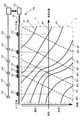
- the change over time in the vehicle position is shown by a diagram in which the vehicle position is on the horizontal axis and the time is on the vertical axis, as shown in FIG.
- the solid line HP1 shown in FIG. 1 shows the change over time of the vehicle position with respect to the vehicle 101 passing through the up lane
- the dotted line HP2 shows the change with time of the vehicle position with respect to the vehicle 101 passing through the down lane (not shown). show.
- the solid line HP1 and the dotted line HP2 in the region surrounded by the alternate long and short dash line P are examples of changes over time in the vehicle position from the past to the present.
- Information indicating the change over time of the vehicle position from the past to the present, that is, the history of the vehicle position is referred to as history information.
- the solid line HP1 and the dotted line HP2 in the region surrounded by the alternate long and short dash line F provide information indicating the predicted future vehicle position change over time, which is an example of the predicted future vehicle position change over time. , Called forecast information.
- an example of generating historical information of a vehicle 101 heading in one direction (a vehicle 101 traveling in an up lane) will be described. Then, based on the generated history information, an example of acquiring traffic parameters, detecting abnormal events, predicting changes in vehicle position over time, predicting the occurrence of abnormal events, presenting traffic control means, and the like will be described. ..
- the traffic parameters, the detection of abnormal events, and the change over time in the vehicle position are based on the change over time in the vehicle position of the vehicle 101 traveling in the opposite direction. It is possible to predict the occurrence of abnormal events and present traffic control means.
- the traffic monitoring device 104 includes an input unit 105, a position acquisition unit 106, a history generation unit 107, a first learning model storage unit 108, a traffic condition acquisition unit 109, and an abnormality detection unit 110. , Event-specific history pattern storage unit 111, prediction unit 112, second learning model storage unit 113, abnormality prediction unit 114, control unit 115, display unit 116, display control unit 117, and image pickup control unit 118. And a communication unit 119.
- the input unit 105 is a keyboard, mouse, touch panel, etc. for the user to input instructions and the like.
- the position acquisition unit 106 acquires the position information on the road R obtained based on the optical fiber sensing using the optical fiber OF laid on the road R from the sensing device 102.
- the position acquisition unit 106 repeatedly acquires the position information on the road R obtained based on the amount of change in the optical interference intensity observed by the sensing device 102 from the sensing device 102.
- the position information will be described by an example obtained based on optical fiber sensing, but the information can be obtained from various sensors set on the road R such as a CCTV camera and a traffic meter (coil). It may be obtained based on. Further, the position information may be acquired based on the probe information of ETC (Electronic Toll Collection System) 2.0 or the like.
- ETC Electronic Toll Collection System
- the history generation unit 107 generates history information indicating changes over time in the vehicle position from the past to the present, based on the position information acquired by the position acquisition unit 106.
- the position information is included in the observation information acquired based on the optical signal input at a constant frequency as described above. Therefore, the position information repeatedly acquired by the position acquisition unit 106 indicates discrete vehicle positions, although the time interval is relatively short.
- the history generation unit 107 takes a discrete vehicle position as an input, and generates history information that continuously shows the change over time of the vehicle position according to the first learning model as shown by the line HP1 in FIG.
- the history generation unit 107 may generate history information indicating the obtained approximate curve, approximate straight line, or a combination thereof by obtaining an approximate curve, an approximate straight line, or a combination thereof of discrete vehicle positions. ..
- the first learning model storage unit 108 is a storage unit for storing the first learning model referred to by the history generation unit 107 in advance.
- the first learning model is a trained learning model that has been machine-learned to generate history information by inputting position information included in the observation information from the sensing device 102. Supervised learning should be adopted for learning the first learning model.
- the teacher data in this case may be created based on the probe information of the vehicle 101 actually traveled, the in-vehicle camera, and the like.
- the traffic condition acquisition unit 109 obtains the value of the traffic parameter based on the history information.
- the abnormality detection unit 110 detects an abnormal event on the road R based on the change over time of the vehicle position indicated by the history information generated by the history generation unit 107 and the event-specific history pattern.
- the event-specific history pattern shows the pattern of changes over time in the vehicle position corresponding to the type of abnormal event on the road R.
- the event-specific history pattern storage unit 111 is a storage unit for storing event-specific history pattern information indicating the event-specific history pattern in advance, and is referred to by the abnormality detection unit 110.
- the prediction unit 112 predicts information about the road R based on the type of the detected abnormal event and the history information generated by the history generation unit 107. To generate. For example, the prediction unit 112 outputs the prediction information about the road based on the second learning model by inputting the history information generated by the history generation unit 107 and the type of the abnormal event detected by the abnormality detection unit 110. do.
- the second learning model storage unit 113 is a storage unit for storing the second learning model referred to by the prediction unit 112 in advance.
- the second learning model is a trained learning model that has been machine-learned to generate prediction information by inputting the first history information for training and the type of detected abnormal event.
- Supervised learning should be adopted for learning of the second learning model.
- the teacher data it is preferable to adopt data indicating the past history information that actually occurred and the type of the abnormal event.
- the prediction unit 112 temporally predicts the vehicle position for the road R based on the history information generated by the history generation unit 107. Predictive information indicating changes may be output. In this case, the prediction unit 112 may generate prediction information about the road R based on the second learning model by inputting the history information generated by the history generation unit 107.
- the second learning model in this case is a trained learning model that has been machine-learned to generate prediction information by inputting the first history information for training. Supervised learning should be adopted for learning of the second learning model.
- the teacher data in this case it is preferable to adopt data including past history information that actually occurred.
- the anomaly prediction unit 114 predicts the type of anomalous event that occurs on the road R based on the change over time indicated by the prediction information generated by the prediction unit 112 and the event-specific history pattern.
- the event-specific history pattern is indicated by the event-specific history pattern information stored in the event-specific history pattern storage unit 111.
- the abnormality prediction unit 114 adopts prediction information as information indicating changes in vehicle position over time. do. Except for this point, the functions of the abnormality prediction unit 114 and the abnormality detection unit 110 may be the same.
- Traffic control information includes traffic control means for alleviating abnormal events that are expected to occur.
- Traffic control measures include, for example, at least one of interchange closure, another route to avoid the occurrence point of an abnormal event that is expected to occur, change of road toll, and dispatch plan of emergency personnel.
- the emergency personnel dispatch plan is a plan for dispatching personnel to handle an abnormal event, and includes the number of personnel, the number of emergency vehicles, the arrangement of emergency vehicles to the site, the estimated time of arrival, and the like.
- control unit 115 inputs the type and history information of an abnormal event predicted to occur by the abnormality prediction unit 114, and based on a learning model, the traffic control unit 115 includes a traffic control means for alleviating the abnormal event. Generate information.
- the learning model is a memory that has been machine-learned to generate traffic control information including traffic control means for mitigating the abnormal event by inputting the type and history information of the past abnormal event, which is not shown in advance. It should be stored in the department. Supervised learning is often adopted for learning, and for example, the type of past abnormal event and historical information are input to the teacher data, and the traffic control means effective for alleviating the abnormal event is used. It is recommended that the traffic control information including the information be adopted.
- control unit 115 may hold, for example, control information in which the type of abnormal event and the traffic control means are associated with each other, regardless of the learning model. In this case, the control unit 115 may acquire the traffic control means associated with the type of the abnormal event predicted to occur from the control information, and generate the traffic control information including the acquired traffic control means.
- control unit 115 holds the actual information in advance.
- the actual information includes the traffic control means adopted in the past for each type of abnormal event and the evaluation of the traffic control means.
- the evaluation is represented by, for example, an evaluation value indicating the degree to which the abnormal event is alleviated by the traffic control means, or whether or not the abnormal event is alleviated by the traffic control means.
- control unit 115 generates evaluation information for the traffic control means generated by the control unit 115 based on the actual information.
- the evaluation information is an evaluation value indicating the degree to which the abnormal event predicted to occur by the abnormality predicting unit 114 is alleviated by the traffic control means generated by the control unit 115, or the abnormal event is alleviated by the traffic control means. Indicates whether or not it is expected to be done.
- control unit 115 accepts the traffic control means selected by the user from the traffic control means indicated by the traffic control information generated by the control unit 115, and generates decision information indicating the selected traffic control means.
- the display unit 116 displays the screen.
- the display control unit 117 causes the display unit 116 to display the screen.
- the display control unit 117 may, for example, history information, traffic parameter values, prediction information, a road map showing the location of current or future abnormal events, presentation of traffic control means, traffic control information generated by the control unit 115, and the like.
- the evaluation information, the decision information, and the like are displayed on the screen of the display unit 116.
- the image pickup control unit 118 controls the camera 103 that captures the road R.
- the imaging control unit 118 enlarges the place where the abnormal event occurs to the camera 103 to take a picture.
- the image pickup control unit 118 causes the location camera 103 in which the occurrence of the abnormal event is predicted to take an enlarged image.
- the communication unit 119 communicates with the operation control device 120 mounted on the vehicle 101. It is desirable that the driving control device 120 is a device that controls the automatic driving of the vehicle 101.
- the communication unit 119 transmits information indicating the place where the abnormal event occurs to the operation control device 120.
- the communication unit 119 transmits information indicating the location of the predicted occurrence of the abnormal event to the operation control device 120.
- the communication unit 119 transmits the decision information generated by the control unit 115 to the operation control device 120.
- the traffic monitoring device 102 physically has a bus 1010, a processor 1020, a memory 1030, a storage device 1040, a network interface 1050, and a user interface 1060, as shown in FIG.
- the bus 1010 is a data transmission path for the processor 1020, the memory 1030, the storage device 1040, the network interface 1050, and the user interface 1060 to transmit and receive data to and from each other.
- the method of connecting the processors 1020 and the like to each other is not limited to the bus connection.
- the processor 1020 is a processor realized by a CPU (Central Processing Unit), a GPU (Graphics Processing Unit), or the like.
- the memory 1030 is a main storage device realized by a RAM (RandomAccessMemory) or the like.
- the storage device 1040 is an auxiliary storage device realized by an HDD (Hard Disk Drive), SSD (Solid State Drive), memory card, ROM (Read Only Memory), or the like.
- HDD Hard Disk Drive
- SSD Solid State Drive
- ROM Read Only Memory
- the storage device 1040 realizes a storage unit (first learning model storage unit 108, event-specific history pattern storage unit 111, second learning model storage unit 113) of the traffic monitoring device 102 and a function of holding information.
- the storage device 1040 includes each functional unit (position acquisition unit 106, history generation unit 107, traffic condition acquisition unit 109, abnormality detection unit 110, prediction unit 112, abnormality prediction unit 114, control unit 115, and the image analysis device 102.
- a program module for realizing the display control unit 117, the image pickup control unit 118, and the communication unit 119) is stored.
- the processor 1020 reads each of these program modules into the memory 1030 and executes them, each functional unit corresponding to the program module is realized.
- the network interface 1050 is an interface for connecting the traffic monitoring device 102 to a network configured by wire, wireless, or a combination thereof.
- the traffic monitoring device 102 according to the present embodiment communicates with the sensing device 102, the camera 103, and the operation control device 120 by being connected to the network through the network interface 1050.
- the user interface 1070 is an interface for inputting information from the user and an interface for presenting information to the user, and includes, for example, a mouse as an input unit 105, a keyboard, a touch sensor, and a liquid crystal display as a display unit 116.
- the function of the traffic monitoring device 102 can be realized by executing the software program in cooperation with each physical component. Therefore, the present invention may be realized as a software program (hereinafter, also simply referred to as “program”), or may be realized as a non-temporary storage medium in which the program is recorded.
- program a software program
- FIGS. 4A and 4B are flowcharts showing an example of traffic monitoring processing according to the present embodiment.
- the traffic monitoring process is a process for monitoring the traffic on the road R, and is performed by referring to the position information repeatedly acquired from the sensing device 102, for example, at regular time intervals.
- the traffic monitoring process is started, for example, in response to a user's instruction from the input unit 103.
- the position acquisition unit 106 acquires the vehicle position of the vehicle 101 passing through the road R by acquiring the position information from the sensing device 102 (step S101).
- the history generation unit 107 obtains the change over time of the vehicle position from the past to the present, that is, the history of the vehicle position, based on the vehicle position acquired in step S101 (step S102).
- the history generation unit 107 can obtain the vehicle position at a predetermined time longer than the acquisition cycle of the vehicle position in step S101. It should be done when it is acquired.
- the traffic condition acquisition unit 109 obtains traffic parameters on the road R such as speed (vehicle speed), traffic density, traffic volume, and occupancy rate of the vehicle 101 based on the history of the vehicle position obtained in step S102 (step S103). ).
- the vehicle speed [km / h] is the amount of change in the vehicle position (for example, the distance from the vehicle position P1 to the vehicle position P2 in the figure). , Obtained by dividing by the time required for the change.
- the vehicle speed appears in the slope of the change over time in the vehicle position, and among the lines HPA, HPb, and HPc showing the change over time in the vehicle position, the vehicle 101 corresponding to the line HPa is the fastest, and the line HPc. The corresponding vehicle 101 is the slowest.
- Traffic density [vehicles / km] is the number of vehicles 101 per unit section at a certain moment.
- the traffic density [unit / km] is the line HPa indicating the change over time of the vehicle position that intersects the horizontal line in the area corresponding to the unit interval when the horizontal line corresponding to a certain time is drawn.
- HPa indicating the change over time of the vehicle position that intersects the horizontal line in the area corresponding to the unit interval when the horizontal line corresponding to a certain time is drawn.
- HPb HPc.
- the traffic volume [unit / h] is the number of vehicles 101 passing through a certain point in a unit time.
- the traffic volume [unit / h] shows the change over time of the vehicle position that intersects the vertical line in the area corresponding to the unit time when the vertical line corresponding to a certain point is drawn. It is represented by the number of lines HPa, HPb, HPc.
- the occupancy rate is the ratio of the distance occupied by the vehicle 101 in the target section at a certain moment (spatial occupancy), or the ratio of the time occupied by the vehicle 101 in the target time at a certain point (time occupancy). be. These can be obtained, for example, based on the traffic density, the traffic volume, etc., with the length (vehicle length) of the vehicle 101 as the average length.
- the display control unit 117 causes the display unit 116 to display the value of the traffic parameter obtained in step S103 (step S104).
- the abnormality detection unit 110 occurs on the road R based on the history of the vehicle position obtained in step S102 and the event-specific history pattern indicated by the event-specific history pattern information stored in the event-specific history pattern storage unit 111. Detect the abnormal event that is occurring. Then, the abnormality detection unit 110 determines whether or not an abnormal event has occurred on the road R based on the detection result (step S105).
- the event-specific history pattern includes at least one of a traffic jam pattern corresponding to a traffic jam, a stop pattern corresponding to a vehicle stop, and an obstacle pattern corresponding to a road obstacle.
- FIG. 6 shows an example of a traffic jam pattern, which is a pattern of changes over time in the vehicle position when a traffic jam occurs.
- a traffic jam occurs, the vehicle 101 passes at a speed lower than an appropriately determined reference speed, and the inter-vehicle distance between them becomes shorter than an appropriately determined reference distance. Therefore, as shown in the figure, the traffic jam pattern indicates that the slope of the line indicating the change in the vehicle position of each vehicle 101 indicates a low speed, and that the distance between the vehicle positions P4 to P9 of each vehicle 101 at time T1 is short. Included in its features.
- FIG. 7 shows an example of a stop pattern, which is a pattern of changes over time in the vehicle position when the vehicle 101 stops.
- the stop pattern includes the feature that the vehicle position is constant even with the lapse of time.
- the vehicle 101 gradually decelerates and stops at the vehicle position P10 at time T2. It should be noted that the stop pattern may include the fact that the stop lasts longer than a predetermined time.
- FIG. 8A shows an example of an obstacle pattern, which is a pattern of changes over time in the vehicle position when an obstacle on the road occurs.
- the road obstacle F is at the position P11 of the traveling lane on the road R.
- the vehicle 101 traveling in the traveling lane decelerates from the position 101a in front of the road obstacle F in order to move to the adjacent lane and avoid the road obstacle F.
- the vehicle 101 returns to the traveling lane and accelerates as shown in FIG. 8B.
- the obstacle pattern of FIG. 8A shows that when the road obstacle F is in the driving lane on the road R, after a plurality of vehicles 101 travel at a low speed within a predetermined range from the road obstacle F, Includes the feature of accelerating.
- the obstacle pattern may include decelerating to a speed slower than a predetermined speed.
- event-specific history patterns shown in FIGS. 6 to 8 are merely examples of event-specific history patterns corresponding to various types of abnormal events such as traffic jams, vehicle 101 stops, and road obstacles, respectively.
- Event-specific history pattern information including a plurality of event-specific history patterns for each type of abnormal event may be stored in advance in the event-specific history pattern storage unit 111. Then, the abnormality detection unit 110 obtains the degree of similarity between the history patterns for each event and the history of the vehicle position by collating (for example, pattern matching).
- the abnormality detection unit 110 detects an abnormal event occurring on the current road R, and thus determines that an abnormal event has occurred on the road R (step). S105; Yes). At this time, the type of the abnormal event occurring on the road R is also specified from the type of the abnormal event corresponding to the event-specific history pattern having a high degree of similarity.
- the abnormality detection unit 110 does not detect the abnormal event occurring on the current road R, and therefore determines that no abnormal event has occurred on the road R (step S105; No.). ).
- the abnormality detection unit 110 detects an abnormal event based on the learning model by inputting a change over time in the vehicle position, and when the abnormal event is detected, generates information indicating the type of the abnormal event. You may.
- machine learning has been performed to generate information indicating the type of abnormal event according to the degree of similarity between the change and the history pattern for each event, using the change over time of the vehicle position as an input.
- a learning model should be adopted. This learning may be supervised learning, and the learning model may be stored in advance in a storage unit instead of the event-specific history pattern storage unit 111.
- the abnormality detection unit 110 detects and detects an abnormal event according to whether or not one or a plurality of features of the event-specific history pattern for each type of abnormal event is included in the change over time of the vehicle position.
- the type of anomalous event may be specified.
- step S105 When it is determined that no abnormal event has occurred (step S105; No), the position acquisition unit 106 performs the process of step S101.
- step S105 When it is determined that an abnormal event has occurred (step S105; Yes), the display control unit 117 displays a road map showing the location of the abnormal event on the screen of the display unit 116 (step S106). Further, the image pickup control unit 118 causes the camera 103 to magnify and take a picture of the place where the abnormal event occurs (step S107).
- the prediction unit 112 predicts a future change in the vehicle position with respect to the road R based on the history of the vehicle position obtained in step S102 and the type of the abnormal event detected in step S105 (step). S108).
- the future change in vehicle position predicted here is, for example, the change in vehicle position over time indicated by the solid line HP1 in the region surrounded by the alternate long and short dash line F in FIG. 1.
- the abnormality prediction unit 114 is based on the time-dependent change in the future vehicle position predicted in step 108 and the event-specific history pattern indicated by the event-specific history pattern information stored in the event-specific history pattern storage unit 111. Predict anomalous events that occur on road R. Then, the abnormality prediction unit 114 determines whether or not the occurrence of an abnormal event is predicted on the road R based on the prediction result (step S109).
- the method of predicting the occurrence of an abnormal event in step S109 is substantially the same as that in which the history of the vehicle position in the process of step S105 is replaced with the change over time of the future vehicle position.
- step S109 when the similarity is larger than the predetermined threshold value as in step S105, the abnormality prediction unit 114 determines that the occurrence of an abnormal event is predicted on the road R (step S109; Yes). ). At this time, the type of the abnormal event predicted to occur on the road R is also specified from the type of the abnormal event corresponding to the event-specific history pattern having a high degree of similarity.
- the abnormality prediction unit 114 determines that the occurrence of an abnormal event is not predicted on the road R (step S109; No).
- step S109 When it is determined that the occurrence of an abnormal event is not predicted (step S109; No), the position acquisition unit 106 performs the process of step S101 with reference to FIG. 4A again.
- step S109 when it is determined that the occurrence of an abnormal event is predicted (step S109; Yes), the display control unit 117 is a place on the screen of the display unit 116 where the occurrence of the abnormal event is predicted. A road map showing the predicted occurrence location is displayed (step S110). Further, the communication unit 119 transmits the predicted occurrence location information indicating the predicted occurrence location of the abnormal event to the operation control device 120 (step S111).
- the control unit 115 performs a traffic control process (step S112) for traffic control to mitigate an abnormal event that is currently occurring and an abnormal event that is expected to occur in the future.
- FIG. 9 is a flowchart showing the details of the traffic control process (step S112).
- the control unit 115 generates traffic control information based on the type of the abnormal event determined to occur in step S109 (step S201).
- the display control unit 117 causes the display unit 116 to display the traffic control information generated in step S201 (step S202).
- the traffic control means included in the traffic control information is to close the interchange in front of the predicted location of traffic congestion, temporarily raise the toll from the tollhouse, and present another route to avoid the predicted location. And so on. Another route may be searched based on the map information and the predicted occurrence location.
- the traffic control means included in the traffic control information may include an emergency personnel dispatch plan for handling the traffic accident.
- the control unit 115 extracts the traffic control means having an option from the traffic control means included in the traffic control information generated in step S201 (step S302).
- a traffic control means with options there can be an example in which a plurality of different routes are presented as a traffic control means.
- the control unit 115 generates evaluation information for each option for the traffic control means extracted in step S302 (step S204).
- the display control unit 117 causes the display unit 116 to display the evaluation information generated in step 204 (step S205).
- the control unit 115 determines whether or not the user's instruction regarding the adoption / rejection of the traffic control means displayed in step S202 has been accepted (step S206). If it is determined that the user's instruction is not received (step S206; No), the control unit 115 continues the process of step S205 until the instruction is received.
- control unit 115 When it is determined that the user's instruction has been accepted (step S206), the control unit 115 outputs the traffic control means adopted by the user as decision information (step S207).
- the user can select the traffic control means to be actually adopted by referring to the traffic control means displayed in step S202 and the evaluation displayed in step S205. Then, by instructing the traffic control means to be adopted from the input unit 105, the control unit 115 generates decision information including the traffic control means to be adopted.
- step S203 may not be performed, and the processing of steps S204 to S205 may be performed for all or a predetermined part of the traffic control means included in the traffic control information generated in step S201. ..
- the display control unit 117 causes the display unit 116 to display the determination information output in step 207 (step S208).
- the notification unit 119 transmits the decision information to the driving control device 120 of the automobile (step S209).
- the automobile equipped with the driving control device 120 transmitted in step S109 is an example of the vehicle 101, and it is desirable that the automobile is an autonomous driving vehicle.
- the driving control device 120 can control the traveling of the vehicle in search of a desirable driving route with reference to the determination information.
- step S112 When the traffic control process (step S112) is completed, the position acquisition unit 106 performs the process of step S101 as shown in FIGS. 4B and A.
- the traffic monitoring process is continuously executed, for example, until a user's termination instruction is received from the input unit 105.
- historical information indicating a change over time of the vehicle position is generated based on the position information indicating the vehicle position on the road.
- an abnormal event occurring on the road R is detected based on an event-specific history pattern and a change over time in the vehicle position.
- the change over time in the vehicle position it is possible to grasp the abnormal event occurring on the road R in real time.
- the change in vehicle position over time has a characteristic pattern for each type of abnormal event, by detecting the abnormal event using the history pattern for each event, the abnormal event occurring on the road R can be detected. It can be detected accurately.
- a road map showing the place where an abnormal event occurs is displayed on the screen. This allows the user to easily recognize the place of occurrence.
- the place of occurrence is enlarged by the camera 103 to take a picture. This enables the user to accurately recognize the current state of the place of occurrence in real time.
- the change over time of the vehicle position on the road R is predicted based on the historical information indicating the change over time of the vehicle position.
- Vehicles 101 that change in the same position under similar road conditions often change in the same position in the future, so based on historical information, the change in vehicle position on the road R over time can be accurately performed. Can be predicted.
- the abnormal event occurring on the road R is predicted based on the time-dependent change in the vehicle position predicted on the road R, the history pattern for each event, and the time-dependent change in the vehicle position. ..
- the change over time of the vehicle position predicted on the road R can be predicted accurately over a wide area and from a bird's-eye view. Further, since the change over time of the vehicle position has a characteristic pattern for each type of abnormal event as in the case of detecting the abnormal event currently occurring, the history pattern for each event is used on the road R. It is possible to accurately predict the abnormal events that will occur.
- a road map showing a predicted occurrence location of an abnormal event is displayed on the screen. This allows the user to easily recognize the predicted occurrence location. Further, the predicted generation location is transmitted to the operation control device 120. As a result, it is possible to formulate an operation plan in consideration of the predicted occurrence location, so that efficient movement becomes possible by avoiding a congested location on the road R.
- traffic control information including traffic control means for mitigating the abnormal event is generated based on the type of the abnormal event predicted to occur.
- the abnormal event can be alleviated, so that efficient movement using the road R becomes possible.
- evaluation information for the traffic control means is generated based on the actual information of the traffic control means adopted for the abnormal event in the past.
- the user can select the traffic control means for mitigating the current or future abnormal events by referring to the evaluation based on the past performance. Therefore, there is a high possibility that an effective traffic control means can be selected, and more efficient movement using the road R becomes possible.
- decision information indicating the traffic control means selected by the user is displayed on the screen. This allows the user to easily recognize the decision information. Further, the determination information is transmitted to the operation control device 120. As a result, it is possible to formulate an operation plan in consideration of the decision information, so that it is possible to move efficiently by avoiding a congested place on the road R.
- ⁇ Modification example> In the embodiment, an example of generating historical information of the vehicle 101 heading in one direction has been described. However, as described with reference to FIG. 1, in the history information, the traveling direction of the vehicle 101 can be easily determined depending on whether the inclination is positive or negative, or the direction approaching and distant from the reference position. In this modification, an example of a history generation unit that acquires history information of a vehicle 101 heading in a different direction (for example, a vehicle 101 passing through each of the up lane and the down lane) will be described.
- the history generation unit 207 includes a position change acquisition unit 207a, a traveling direction determination unit 207b, a first generation unit 207c, and a second generation unit 207d. include.
- the position change acquisition unit 207a obtains a change over time in the vehicle position based on the position information repeatedly acquired.
- the traveling direction determining unit 207b has the traveling direction of the vehicle 101 in the first direction or a second direction opposite to the first direction based on the change with time obtained by the position change acquisition unit 207a. To determine.
- the first generation unit 207c generates the first history information indicating the history of the vehicle position regarding the vehicle 101 traveling in the first direction.
- the second generation unit 207d generates the second history information indicating the history of the vehicle position regarding the vehicle 101 traveling in the second direction.
- Such a history generation unit 207 may be adopted in place of the history generation unit 107 in the traffic monitoring device 104 according to the embodiment.
- the traveling direction of the vehicle 101 traveling in the reverse direction is the same as the traveling direction of the vehicle 101 traveling in the opposite lane, for example, the positive and negative of the inclinations of the lines HP1 and HP2 included in the history information shown in FIG. Become.
- the signal intensity of the return light observed in the optical fiber sensing may be used.
- the method for separating which lane each vehicle 101 is traveling in is not limited to the above-mentioned method using the signal strength by optical fiber sensing, and other methods may be adopted.
- the present invention is not limited thereto.
- the present invention also includes a form in which a part or all of the embodiments described above and a modification thereof are appropriately combined, and a form in which the form is appropriately modified.
- a position acquisition means for acquiring position information indicating the vehicle position on the road
- a traffic monitoring device including a history generation means for generating first history information indicating a change over time of the vehicle position based on the position information.
- the abnormality on the road is based on the event-specific history pattern showing the pattern of the change of the vehicle position with time corresponding to the type of the abnormal event on the road and the change of the vehicle position with time shown by the first history information.
- the traffic monitoring device according to 1 or 2 above, further comprising an abnormality detecting means for detecting an event.
- the event-specific history patterns include a traffic jam pattern corresponding to the traffic jam as the abnormal event, a stop pattern corresponding to the vehicle stop as the abnormal event, and an obstacle pattern corresponding to the road obstacle as the abnormal event.
- the traffic monitoring device which includes at least one of the above.
- the traffic monitoring device further including an image pickup control means for controlling the image pickup means for photographing the road, The traffic monitoring device according to any one of 3 to 5, wherein the image pickup control means causes the image pickup means to magnify and take an image when an abnormal event is detected by the abnormality detection means. ..
- the prediction means inputs the first history information generated by the history generation means based on a trained learning model that has been machine-learned to generate the prediction information by inputting the first history information for training.
- the traffic monitoring device according to 7 above, which generates prediction information about the road.
- the traffic monitoring device When an abnormal event is detected by the anomaly detecting means, a change over time in a vehicle position predicted for the road based on the type of the abnormal event and the first history information generated by the history generating means.
- the traffic monitoring device according to any one of 3 to 6 above, further comprising a prediction means for generating prediction information indicating.
- the prediction means is generated by the history generation means based on a trained learning model that has been machine-learned to generate the prediction information by inputting the first history information for training and the type of the abnormal event.
- the traffic monitoring device which generates prediction information about the road by inputting a first history information and a type of anomalous event detected by the anomaly detecting means.
- the traffic monitoring device further comprising an abnormality predicting means for predicting the type of an abnormal event occurring on the road based on the event-specific history pattern and the change over time indicated by the predicted information.
- a control that generates traffic control information including a traffic control means for mitigating the abnormal event based on the type of the abnormal event predicted to occur.
- the traffic monitoring device according to any one of 11 to 13 above, further comprising means.
- the control means further includes the traffic control means adopted for the abnormal event in the past, an evaluation value indicating the degree of relaxation by the traffic control means, or whether or not the control means is relaxed by the traffic control means. Based on the actual information including, the evaluation value indicating the degree to which the abnormal event predicted to occur by the abnormality predicting means is alleviated by the traffic control means generated by the control means, or the traffic control means 14.
- the traffic monitoring device which generates the evaluation information indicating whether or not it is expected to be alleviated by the above.
- the control means further receives the traffic control means selected by the user from the traffic control means indicated by the generated traffic control information, and generates decision information indicating the selected traffic control means 14 or 15 above.
- the traffic control measures 14 to 16 above include at least one of interchange closures, alternative routes to avoid the location of the expected anomalous event, road toll changes, and emergency personnel dispatch plans.
- the traffic monitoring device according to any one.
- the history generation means is A position change acquisition means for obtaining a change over time in the vehicle position based on the position information, A traveling direction determining means for determining whether the traveling direction of the vehicle is the first direction or the second direction opposite to the first direction based on the obtained change with time.
- a first generation means for generating the first history information about the vehicle traveling in the first direction,
- the traffic monitoring device according to any one of 1 to 19, wherein the traffic monitoring device includes a second generation means for generating second history information indicating a change in the vehicle position with respect to the vehicle traveling in the second direction.
- a traffic condition acquisition means for obtaining a value of a traffic parameter indicating the traffic condition of the road based on the first history information.
- the traffic parameters indicate the speed of a vehicle traveling on the road, the traffic density of the road, the traffic volume which is the amount of vehicles traveling at a predetermined point on the road per unit time, and the occupancy indicating the ratio of the road occupied by the vehicle.
- the traffic monitoring device according to any one of 1 to 20 above, which comprises at least one of the rates.
- the traffic monitoring device according to any one of 1 to 21 above, and An optical fiber laid on the road and end-treated to suppress the reflection of optical signals at one end. It is equipped with a sensing device that inputs an optical signal to the optical fiber and observes the amount of change in the optical interference intensity, which is the intensity of the light that the backscattered light generated by the input of the optical signal interferes with each other.
- the position acquisition means is a traffic monitoring system that acquires the position information on the road obtained based on the amount of change in the optical interference intensity observed by the sensing device.
- the computer Acquiring location information indicating the vehicle position on the road,
- a traffic monitoring method including generating first history information indicating a change over time of the vehicle position based on the position information.
- a program for generating and executing first history information indicating a change over time of the vehicle position based on the position information On the computer Acquiring location information indicating the vehicle position on the road, A program for generating and executing first history information indicating a change over time of the vehicle position based on the position information.
- Traffic monitoring system 101 Vehicle 102 Sensing device 103 Camera 104 Traffic monitoring device 105 Input unit 106 Position acquisition unit 107, 207 History generation unit 108 First learning model storage unit 109 Traffic status acquisition unit 110 Abnormality detection unit 111 Event-specific history pattern storage Unit 112 Prediction unit 113 Second learning model storage unit 114 Abnormality prediction unit 115 Control unit 116 Display unit 117 Display control unit 118 Imaging control unit 119 Communication unit 120 Operation control device 207a Position change acquisition unit 207b Travel direction determination unit 207c First generation Part 207d Second generation part
Abstract
Le but de la présente invention est de déterminer de manière holistique des conditions de trafic sur une large plage en temps réel. Le dispositif de surveillance de trafic (102) comprend : une unité d'acquisition de position (106) qui acquiert des informations de position indiquant des positions de véhicule sur une route ; et une unité de génération d'historique (107) qui génère des informations d'historique indiquant des changements dans les positions de véhicule dans le temps sur la base des informations de position. L'unité d'acquisition de position (106) acquiert les informations de position qui sont obtenues, par exemple, sur la base d'une détection de fibre optique utilisant des fibres optiques disposées dans la chaussée. Le dispositif de surveillance de trafic (102) peut en outre comprendre une unité de détection d'anomalie (107) qui détecte des événements anormaux sur la route sur la base de : motifs d'historique spécifiques d'événements qui indiquent des motifs dans les changements des positions de véhicule dans le temps, qui correspondent à des types individuels d'événements anormaux sur la route ; et les changements des positions du véhicule dans le temps.
Priority Applications (3)
| Application Number | Priority Date | Filing Date | Title |
|---|---|---|---|
| PCT/JP2020/028845 WO2022024208A1 (fr) | 2020-07-28 | 2020-07-28 | Dispositif de surveillance de trafic, système de surveillance de trafic, procédé de surveillance de trafic et programme |
| US18/017,466 US20230274634A1 (en) | 2020-07-28 | 2020-07-28 | Traffic monitoring apparatus, traffic monitoring system, traffic monitoring method, and storage medium |
| JP2022539825A JPWO2022024208A1 (fr) | 2020-07-28 | 2020-07-28 |
Applications Claiming Priority (1)
| Application Number | Priority Date | Filing Date | Title |
|---|---|---|---|
| PCT/JP2020/028845 WO2022024208A1 (fr) | 2020-07-28 | 2020-07-28 | Dispositif de surveillance de trafic, système de surveillance de trafic, procédé de surveillance de trafic et programme |
Publications (1)
| Publication Number | Publication Date |
|---|---|
| WO2022024208A1 true WO2022024208A1 (fr) | 2022-02-03 |
Family
ID=80037778
Family Applications (1)
| Application Number | Title | Priority Date | Filing Date |
|---|---|---|---|
| PCT/JP2020/028845 WO2022024208A1 (fr) | 2020-07-28 | 2020-07-28 | Dispositif de surveillance de trafic, système de surveillance de trafic, procédé de surveillance de trafic et programme |
Country Status (3)
| Country | Link |
|---|---|
| US (1) | US20230274634A1 (fr) |
| JP (1) | JPWO2022024208A1 (fr) |
| WO (1) | WO2022024208A1 (fr) |
Cited By (4)
| Publication number | Priority date | Publication date | Assignee | Title |
|---|---|---|---|---|
| CN115331455A (zh) * | 2022-06-29 | 2022-11-11 | 北京见合八方科技发展有限公司 | 一种公路车辆车道级定位与车辆境况监测方法和系统 |
| CN115346370A (zh) * | 2022-08-10 | 2022-11-15 | 重庆大学 | 基于智能交通的路口防碰撞系统及方法 |
| CN115410403A (zh) * | 2022-04-19 | 2022-11-29 | 北京见合八方科技发展有限公司 | 基于无源感知的公路车辆定位追踪方法、装置及可读介质 |
| CN115544198A (zh) * | 2022-10-25 | 2022-12-30 | 北京磁浮有限公司 | 城市轨道交通运行状态的监测方法及相关装置 |
Citations (9)
| Publication number | Priority date | Publication date | Assignee | Title |
|---|---|---|---|---|
| JPH1019510A (ja) * | 1996-06-27 | 1998-01-23 | Toyota Motor Corp | 路上物体検出装置 |
| JP2004523042A (ja) * | 2001-02-15 | 2004-07-29 | キネテイツク・リミテツド | 道路交通モニタリングシステム |
| JP2004524618A (ja) * | 2001-02-15 | 2004-08-12 | キネティック リミテッド | 道路交通モニターシステム |
| JP2016095695A (ja) * | 2014-11-14 | 2016-05-26 | インターナショナル・ビジネス・マシーンズ・コーポレーションInternational Business Machines Corporation | 移動体が特定領域に接近していることを通知する方法、並びに、その為のサーバ・コンピュータ及びサーバ・コンピュータ・プログラム |
| WO2017047687A1 (fr) * | 2015-09-17 | 2017-03-23 | 株式会社日立国際電気 | Système de surveillance |
| JP2017215759A (ja) * | 2016-05-31 | 2017-12-07 | 株式会社東芝 | 事故予報システム、および、事故予報方法 |
| JP2018505422A (ja) * | 2014-12-02 | 2018-02-22 | ワング,ケビン,スンリン | 事故回避方法及びシステム |
| JP2018180601A (ja) * | 2017-04-03 | 2018-11-15 | Kddi株式会社 | 検知装置、検知方法及び検知プログラム |
| JP2018198026A (ja) * | 2017-05-25 | 2018-12-13 | 株式会社東芝 | 事故予報システム、および、事故予報方法 |
-
2020
- 2020-07-28 WO PCT/JP2020/028845 patent/WO2022024208A1/fr active Application Filing
- 2020-07-28 US US18/017,466 patent/US20230274634A1/en active Pending
- 2020-07-28 JP JP2022539825A patent/JPWO2022024208A1/ja active Pending
Patent Citations (10)
| Publication number | Priority date | Publication date | Assignee | Title |
|---|---|---|---|---|
| JPH1019510A (ja) * | 1996-06-27 | 1998-01-23 | Toyota Motor Corp | 路上物体検出装置 |
| JP2004523042A (ja) * | 2001-02-15 | 2004-07-29 | キネテイツク・リミテツド | 道路交通モニタリングシステム |
| JP2004524618A (ja) * | 2001-02-15 | 2004-08-12 | キネティック リミテッド | 道路交通モニターシステム |
| JP2004527030A (ja) * | 2001-02-15 | 2004-09-02 | キネテイツク・リミテツド | 交通監視 |
| JP2016095695A (ja) * | 2014-11-14 | 2016-05-26 | インターナショナル・ビジネス・マシーンズ・コーポレーションInternational Business Machines Corporation | 移動体が特定領域に接近していることを通知する方法、並びに、その為のサーバ・コンピュータ及びサーバ・コンピュータ・プログラム |
| JP2018505422A (ja) * | 2014-12-02 | 2018-02-22 | ワング,ケビン,スンリン | 事故回避方法及びシステム |
| WO2017047687A1 (fr) * | 2015-09-17 | 2017-03-23 | 株式会社日立国際電気 | Système de surveillance |
| JP2017215759A (ja) * | 2016-05-31 | 2017-12-07 | 株式会社東芝 | 事故予報システム、および、事故予報方法 |
| JP2018180601A (ja) * | 2017-04-03 | 2018-11-15 | Kddi株式会社 | 検知装置、検知方法及び検知プログラム |
| JP2018198026A (ja) * | 2017-05-25 | 2018-12-13 | 株式会社東芝 | 事故予報システム、および、事故予報方法 |
Cited By (7)
| Publication number | Priority date | Publication date | Assignee | Title |
|---|---|---|---|---|
| CN115410403A (zh) * | 2022-04-19 | 2022-11-29 | 北京见合八方科技发展有限公司 | 基于无源感知的公路车辆定位追踪方法、装置及可读介质 |
| CN115410403B (zh) * | 2022-04-19 | 2023-11-10 | 北京见合八方科技发展有限公司 | 基于无源感知的公路车辆定位追踪方法、装置及可读介质 |
| CN115331455A (zh) * | 2022-06-29 | 2022-11-11 | 北京见合八方科技发展有限公司 | 一种公路车辆车道级定位与车辆境况监测方法和系统 |
| CN115331455B (zh) * | 2022-06-29 | 2024-03-01 | 北京见合八方科技发展有限公司 | 一种公路车辆车道级定位与车辆境况监测方法和系统 |
| CN115346370A (zh) * | 2022-08-10 | 2022-11-15 | 重庆大学 | 基于智能交通的路口防碰撞系统及方法 |
| CN115346370B (zh) * | 2022-08-10 | 2023-11-03 | 重庆大学 | 基于智能交通的路口防碰撞系统及方法 |
| CN115544198A (zh) * | 2022-10-25 | 2022-12-30 | 北京磁浮有限公司 | 城市轨道交通运行状态的监测方法及相关装置 |
Also Published As
| Publication number | Publication date |
|---|---|
| JPWO2022024208A1 (fr) | 2022-02-03 |
| US20230274634A1 (en) | 2023-08-31 |
Similar Documents
| Publication | Publication Date | Title |
|---|---|---|
| WO2022024208A1 (fr) | Dispositif de surveillance de trafic, système de surveillance de trafic, procédé de surveillance de trafic et programme | |
| US11392120B2 (en) | Planning autonomous motion | |
| JP5932984B2 (ja) | 運転者支援システム、及び、運転者支援システムを駆動する方法 | |
| US11003925B2 (en) | Event prediction system, event prediction method, program, and recording medium having same recorded therein | |
| US20190042857A1 (en) | Information processing system and information processing method | |
| CN103770780A (zh) | 一种车辆主动安全系统告警屏蔽装置 | |
| KR101446546B1 (ko) | 위치기반 실시간 차량정보 표시시스템 | |
| EP2654028A1 (fr) | Système d'avertissement de collision de trafic sensible à l'orientation | |
| CN112289054A (zh) | 道路安全预警方法、obu、rsu、mec设备及系统 | |
| KR20160142182A (ko) | Its 현장장비 통합 제어 장치 및 이를 포함하는 its 현장장비 통합 제어 시스템 | |
| KR20090125795A (ko) | 안전운전 지원장치 | |
| CN110648533A (zh) | 一种交通管控方法、设备、系统及存储介质 | |
| JP2009126503A (ja) | 運転評価装置、運転評価システム、コンピュータプログラム及び運転評価方法 | |
| JP7332020B2 (ja) | 光ファイバセンシングシステム、道路監視方法、及び光ファイバセンシング機器 | |
| CN110733496A (zh) | 信息处理装置、信息处理方法以及记录介质 | |
| CN111746274A (zh) | 车辆用显示装置、显示控制方法以及存储介质 | |
| Jacob et al. | Vehicle trajectory analysis: an advanced tool for road safety | |
| JP4580995B2 (ja) | 道路交通管制システム | |
| CN109789878A (zh) | 车载电子控制装置 | |
| JP2023024857A (ja) | 路車間連携情報処理方法、装置、システム、電子機器、記憶媒体およびコンピュータプログラム | |
| JP4311647B2 (ja) | 管理装置及び管理システム及び管理方法及びプログラム | |
| JP4128962B2 (ja) | 道路交通管制システム | |
| JP7468633B2 (ja) | 状態推定方法、状態推定装置、及びプログラム | |
| JP7424394B2 (ja) | 車両監視システム、車両監視方法、及び車両監視装置 | |
| JP7167812B2 (ja) | 車両用制御装置、方法、プログラムおよび車両用表示装置 |
Legal Events
| Date | Code | Title | Description |
|---|---|---|---|
| 121 | Ep: the epo has been informed by wipo that ep was designated in this application |
Ref document number: 20947782 Country of ref document: EP Kind code of ref document: A1 |
|
| ENP | Entry into the national phase |
Ref document number: 2022539825 Country of ref document: JP Kind code of ref document: A |
|
| NENP | Non-entry into the national phase |
Ref country code: DE |
|
| 122 | Ep: pct application non-entry in european phase |
Ref document number: 20947782 Country of ref document: EP Kind code of ref document: A1 |