WO2022024208A1 - Traffic monitoring device, traffic monitoring system, traffic monitoring method, and program - Google Patents
Traffic monitoring device, traffic monitoring system, traffic monitoring method, and program Download PDFInfo
- Publication number
- WO2022024208A1 WO2022024208A1 PCT/JP2020/028845 JP2020028845W WO2022024208A1 WO 2022024208 A1 WO2022024208 A1 WO 2022024208A1 JP 2020028845 W JP2020028845 W JP 2020028845W WO 2022024208 A1 WO2022024208 A1 WO 2022024208A1
- Authority
- WO
- WIPO (PCT)
- Prior art keywords
- traffic
- road
- abnormal event
- information
- vehicle
- Prior art date
Links
- 238000012806 monitoring device Methods 0.000 title claims abstract description 63
- 238000012544 monitoring process Methods 0.000 title claims description 32
- 238000000034 method Methods 0.000 title claims description 28
- 230000002159 abnormal effect Effects 0.000 claims abstract description 141
- 230000005856 abnormality Effects 0.000 claims abstract description 51
- 239000013307 optical fiber Substances 0.000 claims abstract description 41
- 230000008859 change Effects 0.000 claims description 101
- 230000003287 optical effect Effects 0.000 claims description 29
- 238000004891 communication Methods 0.000 claims description 18
- 238000011156 evaluation Methods 0.000 claims description 18
- 238000012549 training Methods 0.000 claims description 6
- 230000000116 mitigating effect Effects 0.000 claims description 5
- 238000003384 imaging method Methods 0.000 claims description 4
- 238000001514 detection method Methods 0.000 abstract description 22
- 230000008569 process Effects 0.000 description 10
- 240000004050 Pentaglottis sempervirens Species 0.000 description 9
- 235000004522 Pentaglottis sempervirens Nutrition 0.000 description 9
- 238000012545 processing Methods 0.000 description 7
- 238000012986 modification Methods 0.000 description 6
- 230000004048 modification Effects 0.000 description 6
- VYPSYNLAJGMNEJ-UHFFFAOYSA-N Silicium dioxide Chemical compound O=[Si]=O VYPSYNLAJGMNEJ-UHFFFAOYSA-N 0.000 description 5
- 230000002547 anomalous effect Effects 0.000 description 5
- 230000036962 time dependent Effects 0.000 description 5
- 239000000523 sample Substances 0.000 description 4
- 206010039203 Road traffic accident Diseases 0.000 description 3
- 238000005516 engineering process Methods 0.000 description 3
- 230000007613 environmental effect Effects 0.000 description 3
- 230000006870 function Effects 0.000 description 3
- 230000005540 biological transmission Effects 0.000 description 2
- 238000010586 diagram Methods 0.000 description 1
- 239000000284 extract Substances 0.000 description 1
- 239000000835 fiber Substances 0.000 description 1
- 238000010191 image analysis Methods 0.000 description 1
- 239000004973 liquid crystal related substance Substances 0.000 description 1
- 238000010801 machine learning Methods 0.000 description 1
- 239000000203 mixture Substances 0.000 description 1
- 230000004044 response Effects 0.000 description 1
- 239000007787 solid Substances 0.000 description 1
- 230000007704 transition Effects 0.000 description 1
Images


Classifications
-
- G—PHYSICS
- G06—COMPUTING; CALCULATING OR COUNTING
- G06V—IMAGE OR VIDEO RECOGNITION OR UNDERSTANDING
- G06V20/00—Scenes; Scene-specific elements
- G06V20/50—Context or environment of the image
- G06V20/52—Surveillance or monitoring of activities, e.g. for recognising suspicious objects
- G06V20/54—Surveillance or monitoring of activities, e.g. for recognising suspicious objects of traffic, e.g. cars on the road, trains or boats
-
- G—PHYSICS
- G06—COMPUTING; CALCULATING OR COUNTING
- G06V—IMAGE OR VIDEO RECOGNITION OR UNDERSTANDING
- G06V10/00—Arrangements for image or video recognition or understanding
- G06V10/70—Arrangements for image or video recognition or understanding using pattern recognition or machine learning
- G06V10/77—Processing image or video features in feature spaces; using data integration or data reduction, e.g. principal component analysis [PCA] or independent component analysis [ICA] or self-organising maps [SOM]; Blind source separation
- G06V10/774—Generating sets of training patterns; Bootstrap methods, e.g. bagging or boosting
-
- G—PHYSICS
- G08—SIGNALLING
- G08G—TRAFFIC CONTROL SYSTEMS
- G08G1/00—Traffic control systems for road vehicles
- G08G1/01—Detecting movement of traffic to be counted or controlled
-
- G—PHYSICS
- G08—SIGNALLING
- G08G—TRAFFIC CONTROL SYSTEMS
- G08G1/00—Traffic control systems for road vehicles
- G08G1/01—Detecting movement of traffic to be counted or controlled
- G08G1/0104—Measuring and analyzing of parameters relative to traffic conditions
- G08G1/0108—Measuring and analyzing of parameters relative to traffic conditions based on the source of data
- G08G1/0112—Measuring and analyzing of parameters relative to traffic conditions based on the source of data from the vehicle, e.g. floating car data [FCD]
-
- G—PHYSICS
- G08—SIGNALLING
- G08G—TRAFFIC CONTROL SYSTEMS
- G08G1/00—Traffic control systems for road vehicles
- G08G1/01—Detecting movement of traffic to be counted or controlled
- G08G1/0104—Measuring and analyzing of parameters relative to traffic conditions
- G08G1/0108—Measuring and analyzing of parameters relative to traffic conditions based on the source of data
- G08G1/0116—Measuring and analyzing of parameters relative to traffic conditions based on the source of data from roadside infrastructure, e.g. beacons
-
- G—PHYSICS
- G08—SIGNALLING
- G08G—TRAFFIC CONTROL SYSTEMS
- G08G1/00—Traffic control systems for road vehicles
- G08G1/01—Detecting movement of traffic to be counted or controlled
- G08G1/0104—Measuring and analyzing of parameters relative to traffic conditions
- G08G1/0125—Traffic data processing
- G08G1/0129—Traffic data processing for creating historical data or processing based on historical data
-
- G—PHYSICS
- G08—SIGNALLING
- G08G—TRAFFIC CONTROL SYSTEMS
- G08G1/00—Traffic control systems for road vehicles
- G08G1/01—Detecting movement of traffic to be counted or controlled
- G08G1/0104—Measuring and analyzing of parameters relative to traffic conditions
- G08G1/0125—Traffic data processing
- G08G1/0133—Traffic data processing for classifying traffic situation
-
- G—PHYSICS
- G08—SIGNALLING
- G08G—TRAFFIC CONTROL SYSTEMS
- G08G1/00—Traffic control systems for road vehicles
- G08G1/01—Detecting movement of traffic to be counted or controlled
- G08G1/0104—Measuring and analyzing of parameters relative to traffic conditions
- G08G1/0137—Measuring and analyzing of parameters relative to traffic conditions for specific applications
- G08G1/0141—Measuring and analyzing of parameters relative to traffic conditions for specific applications for traffic information dissemination
-
- G—PHYSICS
- G08—SIGNALLING
- G08G—TRAFFIC CONTROL SYSTEMS
- G08G1/00—Traffic control systems for road vehicles
- G08G1/01—Detecting movement of traffic to be counted or controlled
- G08G1/0104—Measuring and analyzing of parameters relative to traffic conditions
- G08G1/0137—Measuring and analyzing of parameters relative to traffic conditions for specific applications
- G08G1/0145—Measuring and analyzing of parameters relative to traffic conditions for specific applications for active traffic flow control
-
- G—PHYSICS
- G08—SIGNALLING
- G08G—TRAFFIC CONTROL SYSTEMS
- G08G1/00—Traffic control systems for road vehicles
- G08G1/01—Detecting movement of traffic to be counted or controlled
- G08G1/04—Detecting movement of traffic to be counted or controlled using optical or ultrasonic detectors
-
- G—PHYSICS
- G08—SIGNALLING
- G08G—TRAFFIC CONTROL SYSTEMS
- G08G1/00—Traffic control systems for road vehicles
- G08G1/01—Detecting movement of traffic to be counted or controlled
- G08G1/056—Detecting movement of traffic to be counted or controlled with provision for distinguishing direction of travel
-
- G—PHYSICS
- G08—SIGNALLING
- G08G—TRAFFIC CONTROL SYSTEMS
- G08G1/00—Traffic control systems for road vehicles
- G08G1/09—Arrangements for giving variable traffic instructions
- G08G1/0962—Arrangements for giving variable traffic instructions having an indicator mounted inside the vehicle, e.g. giving voice messages
- G08G1/0967—Systems involving transmission of highway information, e.g. weather, speed limits
- G08G1/096708—Systems involving transmission of highway information, e.g. weather, speed limits where the received information might be used to generate an automatic action on the vehicle control
- G08G1/096716—Systems involving transmission of highway information, e.g. weather, speed limits where the received information might be used to generate an automatic action on the vehicle control where the received information does not generate an automatic action on the vehicle control
-
- G—PHYSICS
- G08—SIGNALLING
- G08G—TRAFFIC CONTROL SYSTEMS
- G08G1/00—Traffic control systems for road vehicles
- G08G1/09—Arrangements for giving variable traffic instructions
- G08G1/0962—Arrangements for giving variable traffic instructions having an indicator mounted inside the vehicle, e.g. giving voice messages
- G08G1/0967—Systems involving transmission of highway information, e.g. weather, speed limits
- G08G1/096708—Systems involving transmission of highway information, e.g. weather, speed limits where the received information might be used to generate an automatic action on the vehicle control
- G08G1/096725—Systems involving transmission of highway information, e.g. weather, speed limits where the received information might be used to generate an automatic action on the vehicle control where the received information generates an automatic action on the vehicle control
-
- G—PHYSICS
- G08—SIGNALLING
- G08G—TRAFFIC CONTROL SYSTEMS
- G08G1/00—Traffic control systems for road vehicles
- G08G1/09—Arrangements for giving variable traffic instructions
- G08G1/0962—Arrangements for giving variable traffic instructions having an indicator mounted inside the vehicle, e.g. giving voice messages
- G08G1/0967—Systems involving transmission of highway information, e.g. weather, speed limits
- G08G1/096766—Systems involving transmission of highway information, e.g. weather, speed limits where the system is characterised by the origin of the information transmission
- G08G1/096775—Systems involving transmission of highway information, e.g. weather, speed limits where the system is characterised by the origin of the information transmission where the origin of the information is a central station
Definitions
- the present invention relates to a traffic monitoring device, a traffic monitoring system, a traffic monitoring method and a program.
- Patent Document 1 discloses a technique for grasping the distribution state of moving objects in a target section on a route from a point A to a point B.
- the route guidance device described in Patent Document 1 calculates the number of moving objects existing in each of the small sections in which the target section is divided into several hundred meters in a certain cross section based on the detection result of the vehicle detector. By doing so, the distribution of moving objects can be grasped.
- Patent Document 1 Several vehicle detectors described in Patent Document 1 are installed in a small section mainly for detecting the speed of a vehicle traveling on a road, the amount of passing traffic, etc. in road traffic, and are widely used in the field of road traffic control. There is a description of.
- Patent Document 2 discloses a technique for supporting the appropriate use of probe information.
- the traffic information management system described in Patent Document 2 calculates a first traffic condition using information acquired from a vehicle detector installed on the road for each of a plurality of sections of the road, and travels on the road.
- the second traffic condition is calculated using the probe information acquired from the vehicle. Then, the traffic information management system displays the first traffic condition and the second traffic condition regarding the section where the difference between the first traffic condition and the second traffic condition is equal to or more than a predetermined threshold value on the display unit.
- the traffic conditions in one section of the road may affect other sections, so for road control, it is desirable to be able to grasp the traffic conditions of moving objects on the road from a bird's-eye view over a wide area.
- it is desirable to be able to grasp the traffic conditions on the road in real time because the traffic conditions change from moment to moment, for example, when there is a traffic accident, traffic jams occur in a relatively short time.
- the distribution state of the moving body in the target section grasped by the technique described in Patent Document 1 is the number of moving bodies existing in each of the small sections divided by the target section, and the traffic condition of the moving body on the road is determined. It is difficult to grasp in real time from a bird's-eye view over a wide area.
- the present invention has been made in view of the above circumstances, and an object of the present invention is to provide a traffic monitoring device, a traffic monitoring system, a traffic monitoring method, and a program capable of grasping a wide area traffic situation in real time from a bird's-eye view. And.
- the traffic monitoring device is A position acquisition means for acquiring position information indicating the vehicle position on the road, and A history generation means for generating a first history information indicating a change over time of the vehicle position based on the position information is provided.
- the traffic monitoring system is With the above traffic monitoring device, An optical fiber laid on the road and end-treated to suppress the reflection of optical signals at one end. It is equipped with a sensing device that inputs an optical signal to the optical fiber and observes the amount of change in the optical interference intensity, which is the intensity of the light that the backscattered light generated by the input of the optical signal interferes with each other.
- the position acquisition means acquires the position information on the road obtained based on the amount of change in the optical interference intensity observed by the sensing device.
- the traffic monitoring method is The computer Acquiring location information indicating the vehicle position on the road, It includes generating first history information indicating a change over time of the vehicle position based on the position information.
- the program according to the fourth aspect of the present invention is Acquiring location information indicating the vehicle position on the road,
- the purpose is to generate first history information indicating a change over time in the vehicle position based on the position information.
- the traffic monitoring system 100 is a system for monitoring the traffic of the vehicle 101 traveling on the road R by using the optical fiber sensing technology.
- the road R is typically a highway, but may be any other general road.
- the vehicle 101 is an automobile, a motorcycle, a bus, a truck, or the like.
- the traffic monitoring system 100 includes an optical fiber OF, a sensing device 102, a camera 103, and a traffic monitoring device 104.
- the optical fiber OF is an optical fiber cable laid on the road R.
- the optical fiber OF is, for example, one core of a multi-core optical fiber cable for communication generally laid on the shoulder of a highway or a median strip, and a sensing device 102 is connected to one end thereof. The other end is subjected to a termination process that suppresses the reflection of optical signals.
- a plurality of fiber cables among the multi-core optical fiber cables may be adopted as the optical fiber OF for optical fiber sensing.
- the sensing device 102 inputs an optical signal to the optical fiber OF, and observes the amount of change in the optical interference intensity, which is the intensity of the light in which the backscattered light generated by the input of the optical signal interferes with each other.
- the sensing device 102 inputs a pulse waveform optical signal from one end of the optical fiber OF.
- weak return light called backscattered light is generated from all positions of the optical fiber OF.
- the sensing device 102 observes the backscattered light.
- the structure and characteristic parameters of the quartz glass constituting the optical fiber change with the environmental change, and the signal quality of the backscattered light from the place where the change occurs also changes. ..
- the phase state of the backscattered light changes. This change in the phase state of the backscattered light is observed as a change in light intensity due to interference with other backscattered light received at the same time. That is, the sensing device 102 inputs an optical signal to the optical fiber OF and observes the amount of change in the optical interference intensity caused by the application of vibration.
- the location of vibration is calculated from the round-trip time from the input of the optical signal to the observation of backscattered light and the propagation speed of the optical signal.
- the optical signal is repeatedly input at a constant frequency so that the backscattered light from the other end of the optical fiber OF (that is, the farthest end when viewed from the sensing device 102) and the optical signal to be input next are not mixed. Ru. This makes it possible to accurately and in real time observe the transition of environmental changes such as vibrations that occur around the optical fiber OF.
- optical fiber sensing is a technology for detecting the location of vibration using the optical fiber OF as a sensing medium.
- a general optical fiber OF which is a transmission medium for communication data, can be used as a linear passive sensor, so traffic conditions over a wide area can be displayed in real time without installing a new sensor. Can be grasped.
- the camera 103 is an example of an image pickup means for photographing the road R in order to grasp the traffic condition of the road R.
- the camera 103 is, for example, a CCTV (closed-circuit television) camera installed at intervals on the road R.
- the traffic monitoring device 104 repeatedly acquires observation information including the location of vibration on the road R from the sensing device 102.
- the place where the vibration occurs corresponds to the position (vehicle position) of the vehicle 101 on the road R. Therefore, the observation information includes position information indicating the vehicle position.
- the traffic monitoring device 104 obtains a change over time in the vehicle position from the position information repeatedly acquired. Then, the traffic monitoring device 104 calculates a traffic parameter indicating the traffic condition of the road based on the change with time of the vehicle position, detects an abnormal event occurring on the road R, and changes the vehicle position with time in the future. Predicts the occurrence of abnormal events, and provides traffic control support including presentation of traffic control means.
- the road obstacle means that an obstacle to the passage of the vehicle 101 (for example, a vehicle stopped in an accident, a dropped load, a flying object due to a strong wind) exists on the road.
- Examples of traffic parameters are the speed of the vehicle 101 traveling on the road R, the traffic density of the road R, the traffic volume which is the amount of the vehicle 101 traveling at a predetermined point on the road R per unit time, and the road R being a vehicle.
- the occupancy rate (occupancy) indicating the ratio occupied by 101 can be mentioned.
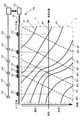
- the change over time in the vehicle position is shown by a diagram in which the vehicle position is on the horizontal axis and the time is on the vertical axis, as shown in FIG.
- the solid line HP1 shown in FIG. 1 shows the change over time of the vehicle position with respect to the vehicle 101 passing through the up lane
- the dotted line HP2 shows the change with time of the vehicle position with respect to the vehicle 101 passing through the down lane (not shown). show.
- the solid line HP1 and the dotted line HP2 in the region surrounded by the alternate long and short dash line P are examples of changes over time in the vehicle position from the past to the present.
- Information indicating the change over time of the vehicle position from the past to the present, that is, the history of the vehicle position is referred to as history information.
- the solid line HP1 and the dotted line HP2 in the region surrounded by the alternate long and short dash line F provide information indicating the predicted future vehicle position change over time, which is an example of the predicted future vehicle position change over time. , Called forecast information.
- an example of generating historical information of a vehicle 101 heading in one direction (a vehicle 101 traveling in an up lane) will be described. Then, based on the generated history information, an example of acquiring traffic parameters, detecting abnormal events, predicting changes in vehicle position over time, predicting the occurrence of abnormal events, presenting traffic control means, and the like will be described. ..
- the traffic parameters, the detection of abnormal events, and the change over time in the vehicle position are based on the change over time in the vehicle position of the vehicle 101 traveling in the opposite direction. It is possible to predict the occurrence of abnormal events and present traffic control means.
- the traffic monitoring device 104 includes an input unit 105, a position acquisition unit 106, a history generation unit 107, a first learning model storage unit 108, a traffic condition acquisition unit 109, and an abnormality detection unit 110. , Event-specific history pattern storage unit 111, prediction unit 112, second learning model storage unit 113, abnormality prediction unit 114, control unit 115, display unit 116, display control unit 117, and image pickup control unit 118. And a communication unit 119.
- the input unit 105 is a keyboard, mouse, touch panel, etc. for the user to input instructions and the like.
- the position acquisition unit 106 acquires the position information on the road R obtained based on the optical fiber sensing using the optical fiber OF laid on the road R from the sensing device 102.
- the position acquisition unit 106 repeatedly acquires the position information on the road R obtained based on the amount of change in the optical interference intensity observed by the sensing device 102 from the sensing device 102.
- the position information will be described by an example obtained based on optical fiber sensing, but the information can be obtained from various sensors set on the road R such as a CCTV camera and a traffic meter (coil). It may be obtained based on. Further, the position information may be acquired based on the probe information of ETC (Electronic Toll Collection System) 2.0 or the like.
- ETC Electronic Toll Collection System
- the history generation unit 107 generates history information indicating changes over time in the vehicle position from the past to the present, based on the position information acquired by the position acquisition unit 106.
- the position information is included in the observation information acquired based on the optical signal input at a constant frequency as described above. Therefore, the position information repeatedly acquired by the position acquisition unit 106 indicates discrete vehicle positions, although the time interval is relatively short.
- the history generation unit 107 takes a discrete vehicle position as an input, and generates history information that continuously shows the change over time of the vehicle position according to the first learning model as shown by the line HP1 in FIG.
- the history generation unit 107 may generate history information indicating the obtained approximate curve, approximate straight line, or a combination thereof by obtaining an approximate curve, an approximate straight line, or a combination thereof of discrete vehicle positions. ..
- the first learning model storage unit 108 is a storage unit for storing the first learning model referred to by the history generation unit 107 in advance.
- the first learning model is a trained learning model that has been machine-learned to generate history information by inputting position information included in the observation information from the sensing device 102. Supervised learning should be adopted for learning the first learning model.
- the teacher data in this case may be created based on the probe information of the vehicle 101 actually traveled, the in-vehicle camera, and the like.
- the traffic condition acquisition unit 109 obtains the value of the traffic parameter based on the history information.
- the abnormality detection unit 110 detects an abnormal event on the road R based on the change over time of the vehicle position indicated by the history information generated by the history generation unit 107 and the event-specific history pattern.
- the event-specific history pattern shows the pattern of changes over time in the vehicle position corresponding to the type of abnormal event on the road R.
- the event-specific history pattern storage unit 111 is a storage unit for storing event-specific history pattern information indicating the event-specific history pattern in advance, and is referred to by the abnormality detection unit 110.
- the prediction unit 112 predicts information about the road R based on the type of the detected abnormal event and the history information generated by the history generation unit 107. To generate. For example, the prediction unit 112 outputs the prediction information about the road based on the second learning model by inputting the history information generated by the history generation unit 107 and the type of the abnormal event detected by the abnormality detection unit 110. do.
- the second learning model storage unit 113 is a storage unit for storing the second learning model referred to by the prediction unit 112 in advance.
- the second learning model is a trained learning model that has been machine-learned to generate prediction information by inputting the first history information for training and the type of detected abnormal event.
- Supervised learning should be adopted for learning of the second learning model.
- the teacher data it is preferable to adopt data indicating the past history information that actually occurred and the type of the abnormal event.
- the prediction unit 112 temporally predicts the vehicle position for the road R based on the history information generated by the history generation unit 107. Predictive information indicating changes may be output. In this case, the prediction unit 112 may generate prediction information about the road R based on the second learning model by inputting the history information generated by the history generation unit 107.
- the second learning model in this case is a trained learning model that has been machine-learned to generate prediction information by inputting the first history information for training. Supervised learning should be adopted for learning of the second learning model.
- the teacher data in this case it is preferable to adopt data including past history information that actually occurred.
- the anomaly prediction unit 114 predicts the type of anomalous event that occurs on the road R based on the change over time indicated by the prediction information generated by the prediction unit 112 and the event-specific history pattern.
- the event-specific history pattern is indicated by the event-specific history pattern information stored in the event-specific history pattern storage unit 111.
- the abnormality prediction unit 114 adopts prediction information as information indicating changes in vehicle position over time. do. Except for this point, the functions of the abnormality prediction unit 114 and the abnormality detection unit 110 may be the same.
- Traffic control information includes traffic control means for alleviating abnormal events that are expected to occur.
- Traffic control measures include, for example, at least one of interchange closure, another route to avoid the occurrence point of an abnormal event that is expected to occur, change of road toll, and dispatch plan of emergency personnel.
- the emergency personnel dispatch plan is a plan for dispatching personnel to handle an abnormal event, and includes the number of personnel, the number of emergency vehicles, the arrangement of emergency vehicles to the site, the estimated time of arrival, and the like.
- control unit 115 inputs the type and history information of an abnormal event predicted to occur by the abnormality prediction unit 114, and based on a learning model, the traffic control unit 115 includes a traffic control means for alleviating the abnormal event. Generate information.
- the learning model is a memory that has been machine-learned to generate traffic control information including traffic control means for mitigating the abnormal event by inputting the type and history information of the past abnormal event, which is not shown in advance. It should be stored in the department. Supervised learning is often adopted for learning, and for example, the type of past abnormal event and historical information are input to the teacher data, and the traffic control means effective for alleviating the abnormal event is used. It is recommended that the traffic control information including the information be adopted.
- control unit 115 may hold, for example, control information in which the type of abnormal event and the traffic control means are associated with each other, regardless of the learning model. In this case, the control unit 115 may acquire the traffic control means associated with the type of the abnormal event predicted to occur from the control information, and generate the traffic control information including the acquired traffic control means.
- control unit 115 holds the actual information in advance.
- the actual information includes the traffic control means adopted in the past for each type of abnormal event and the evaluation of the traffic control means.
- the evaluation is represented by, for example, an evaluation value indicating the degree to which the abnormal event is alleviated by the traffic control means, or whether or not the abnormal event is alleviated by the traffic control means.
- control unit 115 generates evaluation information for the traffic control means generated by the control unit 115 based on the actual information.
- the evaluation information is an evaluation value indicating the degree to which the abnormal event predicted to occur by the abnormality predicting unit 114 is alleviated by the traffic control means generated by the control unit 115, or the abnormal event is alleviated by the traffic control means. Indicates whether or not it is expected to be done.
- control unit 115 accepts the traffic control means selected by the user from the traffic control means indicated by the traffic control information generated by the control unit 115, and generates decision information indicating the selected traffic control means.
- the display unit 116 displays the screen.
- the display control unit 117 causes the display unit 116 to display the screen.
- the display control unit 117 may, for example, history information, traffic parameter values, prediction information, a road map showing the location of current or future abnormal events, presentation of traffic control means, traffic control information generated by the control unit 115, and the like.
- the evaluation information, the decision information, and the like are displayed on the screen of the display unit 116.
- the image pickup control unit 118 controls the camera 103 that captures the road R.
- the imaging control unit 118 enlarges the place where the abnormal event occurs to the camera 103 to take a picture.
- the image pickup control unit 118 causes the location camera 103 in which the occurrence of the abnormal event is predicted to take an enlarged image.
- the communication unit 119 communicates with the operation control device 120 mounted on the vehicle 101. It is desirable that the driving control device 120 is a device that controls the automatic driving of the vehicle 101.
- the communication unit 119 transmits information indicating the place where the abnormal event occurs to the operation control device 120.
- the communication unit 119 transmits information indicating the location of the predicted occurrence of the abnormal event to the operation control device 120.
- the communication unit 119 transmits the decision information generated by the control unit 115 to the operation control device 120.
- the traffic monitoring device 102 physically has a bus 1010, a processor 1020, a memory 1030, a storage device 1040, a network interface 1050, and a user interface 1060, as shown in FIG.
- the bus 1010 is a data transmission path for the processor 1020, the memory 1030, the storage device 1040, the network interface 1050, and the user interface 1060 to transmit and receive data to and from each other.
- the method of connecting the processors 1020 and the like to each other is not limited to the bus connection.
- the processor 1020 is a processor realized by a CPU (Central Processing Unit), a GPU (Graphics Processing Unit), or the like.
- the memory 1030 is a main storage device realized by a RAM (RandomAccessMemory) or the like.
- the storage device 1040 is an auxiliary storage device realized by an HDD (Hard Disk Drive), SSD (Solid State Drive), memory card, ROM (Read Only Memory), or the like.
- HDD Hard Disk Drive
- SSD Solid State Drive
- ROM Read Only Memory
- the storage device 1040 realizes a storage unit (first learning model storage unit 108, event-specific history pattern storage unit 111, second learning model storage unit 113) of the traffic monitoring device 102 and a function of holding information.
- the storage device 1040 includes each functional unit (position acquisition unit 106, history generation unit 107, traffic condition acquisition unit 109, abnormality detection unit 110, prediction unit 112, abnormality prediction unit 114, control unit 115, and the image analysis device 102.
- a program module for realizing the display control unit 117, the image pickup control unit 118, and the communication unit 119) is stored.
- the processor 1020 reads each of these program modules into the memory 1030 and executes them, each functional unit corresponding to the program module is realized.
- the network interface 1050 is an interface for connecting the traffic monitoring device 102 to a network configured by wire, wireless, or a combination thereof.
- the traffic monitoring device 102 according to the present embodiment communicates with the sensing device 102, the camera 103, and the operation control device 120 by being connected to the network through the network interface 1050.
- the user interface 1070 is an interface for inputting information from the user and an interface for presenting information to the user, and includes, for example, a mouse as an input unit 105, a keyboard, a touch sensor, and a liquid crystal display as a display unit 116.
- the function of the traffic monitoring device 102 can be realized by executing the software program in cooperation with each physical component. Therefore, the present invention may be realized as a software program (hereinafter, also simply referred to as “program”), or may be realized as a non-temporary storage medium in which the program is recorded.
- program a software program
- FIGS. 4A and 4B are flowcharts showing an example of traffic monitoring processing according to the present embodiment.
- the traffic monitoring process is a process for monitoring the traffic on the road R, and is performed by referring to the position information repeatedly acquired from the sensing device 102, for example, at regular time intervals.
- the traffic monitoring process is started, for example, in response to a user's instruction from the input unit 103.
- the position acquisition unit 106 acquires the vehicle position of the vehicle 101 passing through the road R by acquiring the position information from the sensing device 102 (step S101).
- the history generation unit 107 obtains the change over time of the vehicle position from the past to the present, that is, the history of the vehicle position, based on the vehicle position acquired in step S101 (step S102).
- the history generation unit 107 can obtain the vehicle position at a predetermined time longer than the acquisition cycle of the vehicle position in step S101. It should be done when it is acquired.
- the traffic condition acquisition unit 109 obtains traffic parameters on the road R such as speed (vehicle speed), traffic density, traffic volume, and occupancy rate of the vehicle 101 based on the history of the vehicle position obtained in step S102 (step S103). ).
- the vehicle speed [km / h] is the amount of change in the vehicle position (for example, the distance from the vehicle position P1 to the vehicle position P2 in the figure). , Obtained by dividing by the time required for the change.
- the vehicle speed appears in the slope of the change over time in the vehicle position, and among the lines HPA, HPb, and HPc showing the change over time in the vehicle position, the vehicle 101 corresponding to the line HPa is the fastest, and the line HPc. The corresponding vehicle 101 is the slowest.
- Traffic density [vehicles / km] is the number of vehicles 101 per unit section at a certain moment.
- the traffic density [unit / km] is the line HPa indicating the change over time of the vehicle position that intersects the horizontal line in the area corresponding to the unit interval when the horizontal line corresponding to a certain time is drawn.
- HPa indicating the change over time of the vehicle position that intersects the horizontal line in the area corresponding to the unit interval when the horizontal line corresponding to a certain time is drawn.
- HPb HPc.
- the traffic volume [unit / h] is the number of vehicles 101 passing through a certain point in a unit time.
- the traffic volume [unit / h] shows the change over time of the vehicle position that intersects the vertical line in the area corresponding to the unit time when the vertical line corresponding to a certain point is drawn. It is represented by the number of lines HPa, HPb, HPc.
- the occupancy rate is the ratio of the distance occupied by the vehicle 101 in the target section at a certain moment (spatial occupancy), or the ratio of the time occupied by the vehicle 101 in the target time at a certain point (time occupancy). be. These can be obtained, for example, based on the traffic density, the traffic volume, etc., with the length (vehicle length) of the vehicle 101 as the average length.
- the display control unit 117 causes the display unit 116 to display the value of the traffic parameter obtained in step S103 (step S104).
- the abnormality detection unit 110 occurs on the road R based on the history of the vehicle position obtained in step S102 and the event-specific history pattern indicated by the event-specific history pattern information stored in the event-specific history pattern storage unit 111. Detect the abnormal event that is occurring. Then, the abnormality detection unit 110 determines whether or not an abnormal event has occurred on the road R based on the detection result (step S105).
- the event-specific history pattern includes at least one of a traffic jam pattern corresponding to a traffic jam, a stop pattern corresponding to a vehicle stop, and an obstacle pattern corresponding to a road obstacle.
- FIG. 6 shows an example of a traffic jam pattern, which is a pattern of changes over time in the vehicle position when a traffic jam occurs.
- a traffic jam occurs, the vehicle 101 passes at a speed lower than an appropriately determined reference speed, and the inter-vehicle distance between them becomes shorter than an appropriately determined reference distance. Therefore, as shown in the figure, the traffic jam pattern indicates that the slope of the line indicating the change in the vehicle position of each vehicle 101 indicates a low speed, and that the distance between the vehicle positions P4 to P9 of each vehicle 101 at time T1 is short. Included in its features.
- FIG. 7 shows an example of a stop pattern, which is a pattern of changes over time in the vehicle position when the vehicle 101 stops.
- the stop pattern includes the feature that the vehicle position is constant even with the lapse of time.
- the vehicle 101 gradually decelerates and stops at the vehicle position P10 at time T2. It should be noted that the stop pattern may include the fact that the stop lasts longer than a predetermined time.
- FIG. 8A shows an example of an obstacle pattern, which is a pattern of changes over time in the vehicle position when an obstacle on the road occurs.
- the road obstacle F is at the position P11 of the traveling lane on the road R.
- the vehicle 101 traveling in the traveling lane decelerates from the position 101a in front of the road obstacle F in order to move to the adjacent lane and avoid the road obstacle F.
- the vehicle 101 returns to the traveling lane and accelerates as shown in FIG. 8B.
- the obstacle pattern of FIG. 8A shows that when the road obstacle F is in the driving lane on the road R, after a plurality of vehicles 101 travel at a low speed within a predetermined range from the road obstacle F, Includes the feature of accelerating.
- the obstacle pattern may include decelerating to a speed slower than a predetermined speed.
- event-specific history patterns shown in FIGS. 6 to 8 are merely examples of event-specific history patterns corresponding to various types of abnormal events such as traffic jams, vehicle 101 stops, and road obstacles, respectively.
- Event-specific history pattern information including a plurality of event-specific history patterns for each type of abnormal event may be stored in advance in the event-specific history pattern storage unit 111. Then, the abnormality detection unit 110 obtains the degree of similarity between the history patterns for each event and the history of the vehicle position by collating (for example, pattern matching).
- the abnormality detection unit 110 detects an abnormal event occurring on the current road R, and thus determines that an abnormal event has occurred on the road R (step). S105; Yes). At this time, the type of the abnormal event occurring on the road R is also specified from the type of the abnormal event corresponding to the event-specific history pattern having a high degree of similarity.
- the abnormality detection unit 110 does not detect the abnormal event occurring on the current road R, and therefore determines that no abnormal event has occurred on the road R (step S105; No.). ).
- the abnormality detection unit 110 detects an abnormal event based on the learning model by inputting a change over time in the vehicle position, and when the abnormal event is detected, generates information indicating the type of the abnormal event. You may.
- machine learning has been performed to generate information indicating the type of abnormal event according to the degree of similarity between the change and the history pattern for each event, using the change over time of the vehicle position as an input.
- a learning model should be adopted. This learning may be supervised learning, and the learning model may be stored in advance in a storage unit instead of the event-specific history pattern storage unit 111.
- the abnormality detection unit 110 detects and detects an abnormal event according to whether or not one or a plurality of features of the event-specific history pattern for each type of abnormal event is included in the change over time of the vehicle position.
- the type of anomalous event may be specified.
- step S105 When it is determined that no abnormal event has occurred (step S105; No), the position acquisition unit 106 performs the process of step S101.
- step S105 When it is determined that an abnormal event has occurred (step S105; Yes), the display control unit 117 displays a road map showing the location of the abnormal event on the screen of the display unit 116 (step S106). Further, the image pickup control unit 118 causes the camera 103 to magnify and take a picture of the place where the abnormal event occurs (step S107).
- the prediction unit 112 predicts a future change in the vehicle position with respect to the road R based on the history of the vehicle position obtained in step S102 and the type of the abnormal event detected in step S105 (step). S108).
- the future change in vehicle position predicted here is, for example, the change in vehicle position over time indicated by the solid line HP1 in the region surrounded by the alternate long and short dash line F in FIG. 1.
- the abnormality prediction unit 114 is based on the time-dependent change in the future vehicle position predicted in step 108 and the event-specific history pattern indicated by the event-specific history pattern information stored in the event-specific history pattern storage unit 111. Predict anomalous events that occur on road R. Then, the abnormality prediction unit 114 determines whether or not the occurrence of an abnormal event is predicted on the road R based on the prediction result (step S109).
- the method of predicting the occurrence of an abnormal event in step S109 is substantially the same as that in which the history of the vehicle position in the process of step S105 is replaced with the change over time of the future vehicle position.
- step S109 when the similarity is larger than the predetermined threshold value as in step S105, the abnormality prediction unit 114 determines that the occurrence of an abnormal event is predicted on the road R (step S109; Yes). ). At this time, the type of the abnormal event predicted to occur on the road R is also specified from the type of the abnormal event corresponding to the event-specific history pattern having a high degree of similarity.
- the abnormality prediction unit 114 determines that the occurrence of an abnormal event is not predicted on the road R (step S109; No).
- step S109 When it is determined that the occurrence of an abnormal event is not predicted (step S109; No), the position acquisition unit 106 performs the process of step S101 with reference to FIG. 4A again.
- step S109 when it is determined that the occurrence of an abnormal event is predicted (step S109; Yes), the display control unit 117 is a place on the screen of the display unit 116 where the occurrence of the abnormal event is predicted. A road map showing the predicted occurrence location is displayed (step S110). Further, the communication unit 119 transmits the predicted occurrence location information indicating the predicted occurrence location of the abnormal event to the operation control device 120 (step S111).
- the control unit 115 performs a traffic control process (step S112) for traffic control to mitigate an abnormal event that is currently occurring and an abnormal event that is expected to occur in the future.
- FIG. 9 is a flowchart showing the details of the traffic control process (step S112).
- the control unit 115 generates traffic control information based on the type of the abnormal event determined to occur in step S109 (step S201).
- the display control unit 117 causes the display unit 116 to display the traffic control information generated in step S201 (step S202).
- the traffic control means included in the traffic control information is to close the interchange in front of the predicted location of traffic congestion, temporarily raise the toll from the tollhouse, and present another route to avoid the predicted location. And so on. Another route may be searched based on the map information and the predicted occurrence location.
- the traffic control means included in the traffic control information may include an emergency personnel dispatch plan for handling the traffic accident.
- the control unit 115 extracts the traffic control means having an option from the traffic control means included in the traffic control information generated in step S201 (step S302).
- a traffic control means with options there can be an example in which a plurality of different routes are presented as a traffic control means.
- the control unit 115 generates evaluation information for each option for the traffic control means extracted in step S302 (step S204).
- the display control unit 117 causes the display unit 116 to display the evaluation information generated in step 204 (step S205).
- the control unit 115 determines whether or not the user's instruction regarding the adoption / rejection of the traffic control means displayed in step S202 has been accepted (step S206). If it is determined that the user's instruction is not received (step S206; No), the control unit 115 continues the process of step S205 until the instruction is received.
- control unit 115 When it is determined that the user's instruction has been accepted (step S206), the control unit 115 outputs the traffic control means adopted by the user as decision information (step S207).
- the user can select the traffic control means to be actually adopted by referring to the traffic control means displayed in step S202 and the evaluation displayed in step S205. Then, by instructing the traffic control means to be adopted from the input unit 105, the control unit 115 generates decision information including the traffic control means to be adopted.
- step S203 may not be performed, and the processing of steps S204 to S205 may be performed for all or a predetermined part of the traffic control means included in the traffic control information generated in step S201. ..
- the display control unit 117 causes the display unit 116 to display the determination information output in step 207 (step S208).
- the notification unit 119 transmits the decision information to the driving control device 120 of the automobile (step S209).
- the automobile equipped with the driving control device 120 transmitted in step S109 is an example of the vehicle 101, and it is desirable that the automobile is an autonomous driving vehicle.
- the driving control device 120 can control the traveling of the vehicle in search of a desirable driving route with reference to the determination information.
- step S112 When the traffic control process (step S112) is completed, the position acquisition unit 106 performs the process of step S101 as shown in FIGS. 4B and A.
- the traffic monitoring process is continuously executed, for example, until a user's termination instruction is received from the input unit 105.
- historical information indicating a change over time of the vehicle position is generated based on the position information indicating the vehicle position on the road.
- an abnormal event occurring on the road R is detected based on an event-specific history pattern and a change over time in the vehicle position.
- the change over time in the vehicle position it is possible to grasp the abnormal event occurring on the road R in real time.
- the change in vehicle position over time has a characteristic pattern for each type of abnormal event, by detecting the abnormal event using the history pattern for each event, the abnormal event occurring on the road R can be detected. It can be detected accurately.
- a road map showing the place where an abnormal event occurs is displayed on the screen. This allows the user to easily recognize the place of occurrence.
- the place of occurrence is enlarged by the camera 103 to take a picture. This enables the user to accurately recognize the current state of the place of occurrence in real time.
- the change over time of the vehicle position on the road R is predicted based on the historical information indicating the change over time of the vehicle position.
- Vehicles 101 that change in the same position under similar road conditions often change in the same position in the future, so based on historical information, the change in vehicle position on the road R over time can be accurately performed. Can be predicted.
- the abnormal event occurring on the road R is predicted based on the time-dependent change in the vehicle position predicted on the road R, the history pattern for each event, and the time-dependent change in the vehicle position. ..
- the change over time of the vehicle position predicted on the road R can be predicted accurately over a wide area and from a bird's-eye view. Further, since the change over time of the vehicle position has a characteristic pattern for each type of abnormal event as in the case of detecting the abnormal event currently occurring, the history pattern for each event is used on the road R. It is possible to accurately predict the abnormal events that will occur.
- a road map showing a predicted occurrence location of an abnormal event is displayed on the screen. This allows the user to easily recognize the predicted occurrence location. Further, the predicted generation location is transmitted to the operation control device 120. As a result, it is possible to formulate an operation plan in consideration of the predicted occurrence location, so that efficient movement becomes possible by avoiding a congested location on the road R.
- traffic control information including traffic control means for mitigating the abnormal event is generated based on the type of the abnormal event predicted to occur.
- the abnormal event can be alleviated, so that efficient movement using the road R becomes possible.
- evaluation information for the traffic control means is generated based on the actual information of the traffic control means adopted for the abnormal event in the past.
- the user can select the traffic control means for mitigating the current or future abnormal events by referring to the evaluation based on the past performance. Therefore, there is a high possibility that an effective traffic control means can be selected, and more efficient movement using the road R becomes possible.
- decision information indicating the traffic control means selected by the user is displayed on the screen. This allows the user to easily recognize the decision information. Further, the determination information is transmitted to the operation control device 120. As a result, it is possible to formulate an operation plan in consideration of the decision information, so that it is possible to move efficiently by avoiding a congested place on the road R.
- ⁇ Modification example> In the embodiment, an example of generating historical information of the vehicle 101 heading in one direction has been described. However, as described with reference to FIG. 1, in the history information, the traveling direction of the vehicle 101 can be easily determined depending on whether the inclination is positive or negative, or the direction approaching and distant from the reference position. In this modification, an example of a history generation unit that acquires history information of a vehicle 101 heading in a different direction (for example, a vehicle 101 passing through each of the up lane and the down lane) will be described.
- the history generation unit 207 includes a position change acquisition unit 207a, a traveling direction determination unit 207b, a first generation unit 207c, and a second generation unit 207d. include.
- the position change acquisition unit 207a obtains a change over time in the vehicle position based on the position information repeatedly acquired.
- the traveling direction determining unit 207b has the traveling direction of the vehicle 101 in the first direction or a second direction opposite to the first direction based on the change with time obtained by the position change acquisition unit 207a. To determine.
- the first generation unit 207c generates the first history information indicating the history of the vehicle position regarding the vehicle 101 traveling in the first direction.
- the second generation unit 207d generates the second history information indicating the history of the vehicle position regarding the vehicle 101 traveling in the second direction.
- Such a history generation unit 207 may be adopted in place of the history generation unit 107 in the traffic monitoring device 104 according to the embodiment.
- the traveling direction of the vehicle 101 traveling in the reverse direction is the same as the traveling direction of the vehicle 101 traveling in the opposite lane, for example, the positive and negative of the inclinations of the lines HP1 and HP2 included in the history information shown in FIG. Become.
- the signal intensity of the return light observed in the optical fiber sensing may be used.
- the method for separating which lane each vehicle 101 is traveling in is not limited to the above-mentioned method using the signal strength by optical fiber sensing, and other methods may be adopted.
- the present invention is not limited thereto.
- the present invention also includes a form in which a part or all of the embodiments described above and a modification thereof are appropriately combined, and a form in which the form is appropriately modified.
- a position acquisition means for acquiring position information indicating the vehicle position on the road
- a traffic monitoring device including a history generation means for generating first history information indicating a change over time of the vehicle position based on the position information.
- the abnormality on the road is based on the event-specific history pattern showing the pattern of the change of the vehicle position with time corresponding to the type of the abnormal event on the road and the change of the vehicle position with time shown by the first history information.
- the traffic monitoring device according to 1 or 2 above, further comprising an abnormality detecting means for detecting an event.
- the event-specific history patterns include a traffic jam pattern corresponding to the traffic jam as the abnormal event, a stop pattern corresponding to the vehicle stop as the abnormal event, and an obstacle pattern corresponding to the road obstacle as the abnormal event.
- the traffic monitoring device which includes at least one of the above.
- the traffic monitoring device further including an image pickup control means for controlling the image pickup means for photographing the road, The traffic monitoring device according to any one of 3 to 5, wherein the image pickup control means causes the image pickup means to magnify and take an image when an abnormal event is detected by the abnormality detection means. ..
- the prediction means inputs the first history information generated by the history generation means based on a trained learning model that has been machine-learned to generate the prediction information by inputting the first history information for training.
- the traffic monitoring device according to 7 above, which generates prediction information about the road.
- the traffic monitoring device When an abnormal event is detected by the anomaly detecting means, a change over time in a vehicle position predicted for the road based on the type of the abnormal event and the first history information generated by the history generating means.
- the traffic monitoring device according to any one of 3 to 6 above, further comprising a prediction means for generating prediction information indicating.
- the prediction means is generated by the history generation means based on a trained learning model that has been machine-learned to generate the prediction information by inputting the first history information for training and the type of the abnormal event.
- the traffic monitoring device which generates prediction information about the road by inputting a first history information and a type of anomalous event detected by the anomaly detecting means.
- the traffic monitoring device further comprising an abnormality predicting means for predicting the type of an abnormal event occurring on the road based on the event-specific history pattern and the change over time indicated by the predicted information.
- a control that generates traffic control information including a traffic control means for mitigating the abnormal event based on the type of the abnormal event predicted to occur.
- the traffic monitoring device according to any one of 11 to 13 above, further comprising means.
- the control means further includes the traffic control means adopted for the abnormal event in the past, an evaluation value indicating the degree of relaxation by the traffic control means, or whether or not the control means is relaxed by the traffic control means. Based on the actual information including, the evaluation value indicating the degree to which the abnormal event predicted to occur by the abnormality predicting means is alleviated by the traffic control means generated by the control means, or the traffic control means 14.
- the traffic monitoring device which generates the evaluation information indicating whether or not it is expected to be alleviated by the above.
- the control means further receives the traffic control means selected by the user from the traffic control means indicated by the generated traffic control information, and generates decision information indicating the selected traffic control means 14 or 15 above.
- the traffic control measures 14 to 16 above include at least one of interchange closures, alternative routes to avoid the location of the expected anomalous event, road toll changes, and emergency personnel dispatch plans.
- the traffic monitoring device according to any one.
- the history generation means is A position change acquisition means for obtaining a change over time in the vehicle position based on the position information, A traveling direction determining means for determining whether the traveling direction of the vehicle is the first direction or the second direction opposite to the first direction based on the obtained change with time.
- a first generation means for generating the first history information about the vehicle traveling in the first direction,
- the traffic monitoring device according to any one of 1 to 19, wherein the traffic monitoring device includes a second generation means for generating second history information indicating a change in the vehicle position with respect to the vehicle traveling in the second direction.
- a traffic condition acquisition means for obtaining a value of a traffic parameter indicating the traffic condition of the road based on the first history information.
- the traffic parameters indicate the speed of a vehicle traveling on the road, the traffic density of the road, the traffic volume which is the amount of vehicles traveling at a predetermined point on the road per unit time, and the occupancy indicating the ratio of the road occupied by the vehicle.
- the traffic monitoring device according to any one of 1 to 20 above, which comprises at least one of the rates.
- the traffic monitoring device according to any one of 1 to 21 above, and An optical fiber laid on the road and end-treated to suppress the reflection of optical signals at one end. It is equipped with a sensing device that inputs an optical signal to the optical fiber and observes the amount of change in the optical interference intensity, which is the intensity of the light that the backscattered light generated by the input of the optical signal interferes with each other.
- the position acquisition means is a traffic monitoring system that acquires the position information on the road obtained based on the amount of change in the optical interference intensity observed by the sensing device.
- the computer Acquiring location information indicating the vehicle position on the road,
- a traffic monitoring method including generating first history information indicating a change over time of the vehicle position based on the position information.
- a program for generating and executing first history information indicating a change over time of the vehicle position based on the position information On the computer Acquiring location information indicating the vehicle position on the road, A program for generating and executing first history information indicating a change over time of the vehicle position based on the position information.
- Traffic monitoring system 101 Vehicle 102 Sensing device 103 Camera 104 Traffic monitoring device 105 Input unit 106 Position acquisition unit 107, 207 History generation unit 108 First learning model storage unit 109 Traffic status acquisition unit 110 Abnormality detection unit 111 Event-specific history pattern storage Unit 112 Prediction unit 113 Second learning model storage unit 114 Abnormality prediction unit 115 Control unit 116 Display unit 117 Display control unit 118 Imaging control unit 119 Communication unit 120 Operation control device 207a Position change acquisition unit 207b Travel direction determination unit 207c First generation Part 207d Second generation part
Abstract
The purpose of the present invention is to holistically ascertain traffic conditions over a broad range in real time. A traffic monitoring device (102) comprises: a position acquisition unit (106) that acquires position information indicating vehicle positions on a roadway; and a history generation unit (107) that generates history information indicating changes in the vehicle positions over time on the basis of the position information. The position acquisition unit (106) acquires the position information that is obtained, for instance, on the basis of optical fiber sensing utilizing optical fibers laid in the roadway. The traffic monitoring device (102) may further comprise an abnormality detection unit (107) that detects abnormal events on the roadway on the basis of: event-specific history patterns that indicate patterns in the changes in the vehicle positions over time, which correspond to individual types of abnormal events on the roadway; and the changes in the vehicle positions over time.
Description
本発明は、交通監視装置、交通監視システム、交通監視方法及びプログラムに関する。
The present invention relates to a traffic monitoring device, a traffic monitoring system, a traffic monitoring method and a program.
特許文献1には、地点Aから地点Bまでの路線上の対象区間での移動体の分布状況を把握する技術が開示されている。特許文献1に記載の経路誘導装置は、ある時断面において、対象区間を数百メートルごとに分割した小区間の各々に存在する移動体の存在台数を、車両感知器の検出結果に基づいて算出することにより、移動体の分布状況を把握する。
Patent Document 1 discloses a technique for grasping the distribution state of moving objects in a target section on a route from a point A to a point B. The route guidance device described in Patent Document 1 calculates the number of moving objects existing in each of the small sections in which the target section is divided into several hundred meters in a certain cross section based on the detection result of the vehicle detector. By doing so, the distribution of moving objects can be grasped.
特許文献1に記載の車両感知器は、主として道路交通において道路上を走行する自動車の速度や通過交通量等を検知するために小区間に数個設置され、道路交通管制分野において広く用いられる旨の記載がある。
Several vehicle detectors described in Patent Document 1 are installed in a small section mainly for detecting the speed of a vehicle traveling on a road, the amount of passing traffic, etc. in road traffic, and are widely used in the field of road traffic control. There is a description of.
しかし、車両感知器(トラフィックカウンタ)はその地点を通過する車両の情報を取得するだけなので、車両感知器その地点を含む区間の車両の平均速度などの情報を正確に取得できるとは限らない。そこで、特許文献2では、プローブ情報の適切な利用を支援する技術を開示する。
However, since the vehicle detector (traffic counter) only acquires information on vehicles passing through that point, it is not always possible to accurately acquire information such as the average speed of vehicles in the section including that point. Therefore, Patent Document 2 discloses a technique for supporting the appropriate use of probe information.
特許文献2に記載の交通情報管理システムは、道路の複数の区間ごとに、道路に設置されている車両感知器から取得した情報を用いて第1の交通状況を算出するとともに、道路を走行する車両から取得したプローブ情報を用いて第2の交通状況を算出する。そして、当該交通情報管理システムは、第1の交通状況と第2の交通状況に所定の閾値以上の差異がある区間に関する第1の交通状況と第2の交通状況を表示部に表示する。
The traffic information management system described in Patent Document 2 calculates a first traffic condition using information acquired from a vehicle detector installed on the road for each of a plurality of sections of the road, and travels on the road. The second traffic condition is calculated using the probe information acquired from the vehicle. Then, the traffic information management system displays the first traffic condition and the second traffic condition regarding the section where the difference between the first traffic condition and the second traffic condition is equal to or more than a predetermined threshold value on the display unit.
一般的に、道路のある区間の交通状況が他の区間に影響することがあるので、道路管制のためには、道路における移動体の交通状況を広域で俯瞰的に把握できることが望ましい。また、道路の交通状況は、例えば交通事故があると比較的短時間で渋滞が発生するなど、時々刻々と変化するものであるので、リアルタイムで把握できることが望ましい。
In general, the traffic conditions in one section of the road may affect other sections, so for road control, it is desirable to be able to grasp the traffic conditions of moving objects on the road from a bird's-eye view over a wide area. In addition, it is desirable to be able to grasp the traffic conditions on the road in real time because the traffic conditions change from moment to moment, for example, when there is a traffic accident, traffic jams occur in a relatively short time.
しかし、特許文献1に記載の技術で把握される対象区間での移動体の分布状況は、対象区間を分割した小区間の各々における移動体の存在台数であり、道路における移動体の交通状況を広域で俯瞰的に、かつ、リアルタイムで把握することが困難である。
However, the distribution state of the moving body in the target section grasped by the technique described in Patent Document 1 is the number of moving bodies existing in each of the small sections divided by the target section, and the traffic condition of the moving body on the road is determined. It is difficult to grasp in real time from a bird's-eye view over a wide area.
また、特許文献2に記載の交通情報管理システムによれば、第1の交通状況と第2の交通状況とに閾値以上の差異がある区間をユーザに知らせることができたとしても、当該区間における交通状況、例えば車両の平均速度を求めることは困難である。従って、特許文献2に記載の技術によっても、道路における移動体の交通状況を広域で俯瞰的に、かつ、リアルタイムで把握することは困難である。
Further, according to the traffic information management system described in Patent Document 2, even if it is possible to notify the user of a section in which there is a difference of more than a threshold value between the first traffic condition and the second traffic condition, the section thereof It is difficult to determine traffic conditions, such as the average speed of a vehicle. Therefore, even with the technique described in Patent Document 2, it is difficult to grasp the traffic condition of a moving object on a road in a wide area from a bird's-eye view and in real time.
本発明は、上述の事情に鑑みてなされたもので、広域の交通状況を俯瞰的にリアルタイムで把握することが可能な交通監視装置、交通監視システム、交通監視方法及びプログラムを提供することを目的とする。
The present invention has been made in view of the above circumstances, and an object of the present invention is to provide a traffic monitoring device, a traffic monitoring system, a traffic monitoring method, and a program capable of grasping a wide area traffic situation in real time from a bird's-eye view. And.
上記目的を達成するため、本発明の第1の観点に係る交通監視装置は、
道路における車両位置を示す位置情報を取得する位置取得手段と、
前記位置情報に基づいて、前記車両位置の経時的な変化を示す第1履歴情報を生成する履歴生成手段とを備える。 In order to achieve the above object, the traffic monitoring device according to the first aspect of the present invention is
A position acquisition means for acquiring position information indicating the vehicle position on the road, and
A history generation means for generating a first history information indicating a change over time of the vehicle position based on the position information is provided.
本発明の第2の観点に係る交通監視システムは、
上記の交通監視装置と、
前記道路に敷設され、光信号の反射を抑制する終端処理が一端に施された光ファイバと、
前記光ファイバに光信号を入力するとともに、当該光信号の入力に伴って生じる後方散乱光同士が干渉した光の強度である光干渉強度の変化量を観測するセンシング装置とを備え、
前記位置取得手段は、前記センシング装置によって観測された前記光干渉強度の変化量に基づいて得られる前記道路における前記位置情報を取得する。 The traffic monitoring system according to the second aspect of the present invention is
With the above traffic monitoring device,
An optical fiber laid on the road and end-treated to suppress the reflection of optical signals at one end.
It is equipped with a sensing device that inputs an optical signal to the optical fiber and observes the amount of change in the optical interference intensity, which is the intensity of the light that the backscattered light generated by the input of the optical signal interferes with each other.
The position acquisition means acquires the position information on the road obtained based on the amount of change in the optical interference intensity observed by the sensing device.
本発明の第3の観点に係る交通監視方法は、
コンピュータが、
道路における車両位置を示す位置情報を取得することと、
前記位置情報に基づいて、前記車両位置の経時的な変化を示す第1履歴情報を生成することとを含む。 The traffic monitoring method according to the third aspect of the present invention is
The computer
Acquiring location information indicating the vehicle position on the road,
It includes generating first history information indicating a change over time of the vehicle position based on the position information.
本発明の第4の観点に係るプログラムは、
道路における車両位置を示す位置情報を取得することと、
前記位置情報に基づいて、前記車両位置の経時的な変化を示す第1履歴情報を生成することとを実行させるためのものである。 The program according to the fourth aspect of the present invention is
Acquiring location information indicating the vehicle position on the road,
The purpose is to generate first history information indicating a change over time in the vehicle position based on the position information.
本発明によれば、広域の交通状況を俯瞰的にリアルタイムで把握することが可能になる。
According to the present invention, it is possible to grasp the traffic situation over a wide area in real time from a bird's-eye view.
以下、本発明の一実施の形態について、図面を参照しつつ説明する。全図を通じて同一の要素には同一の符号を付す。なお、すべての図面において、同様な構成要素には同様の符号を付し、適宜説明を省略する。
Hereinafter, an embodiment of the present invention will be described with reference to the drawings. The same elements are given the same reference numerals throughout the figure. In all drawings, similar components are designated by the same reference numerals, and description thereof will be omitted as appropriate.
<本実施の形態に係る交通監視システムの構成>
本実施の形態に係る交通監視システム100は、図1に示すように、光ファイバセンシング技術を利用して、道路Rを走行する車両101の交通を監視するためのシステムである。道路Rは、典型的には高速道路であるが、一般的なその他の道路であってもよい。また、車両101は、自動車、二輪車、バス、トラックなどである。 <Configuration of traffic monitoring system according to this embodiment>
As shown in FIG. 1, thetraffic monitoring system 100 according to the present embodiment is a system for monitoring the traffic of the vehicle 101 traveling on the road R by using the optical fiber sensing technology. The road R is typically a highway, but may be any other general road. The vehicle 101 is an automobile, a motorcycle, a bus, a truck, or the like.
本実施の形態に係る交通監視システム100は、図1に示すように、光ファイバセンシング技術を利用して、道路Rを走行する車両101の交通を監視するためのシステムである。道路Rは、典型的には高速道路であるが、一般的なその他の道路であってもよい。また、車両101は、自動車、二輪車、バス、トラックなどである。 <Configuration of traffic monitoring system according to this embodiment>
As shown in FIG. 1, the
交通監視システム100は、光ファイバOFと、センシング装置102と、カメラ103と、交通監視装置104とを備える。
The traffic monitoring system 100 includes an optical fiber OF, a sensing device 102, a camera 103, and a traffic monitoring device 104.
光ファイバOFは、道路Rに敷設された光ファイバケーブルである。光ファイバOFは、例えば、一般的に高速道路の路肩部や中央分離帯などに敷設された通信用の多芯光ファイバケーブルのうちの1芯であり、一端にはセンシング装置102が接続され、他端には光信号の反射を抑制する終端処理が施されている。なお、多芯光ファイバケーブルのうちの複数のファイバケーブルが、光ファイバセンシングのための光ファイバOFとして採用されてもよい。
The optical fiber OF is an optical fiber cable laid on the road R. The optical fiber OF is, for example, one core of a multi-core optical fiber cable for communication generally laid on the shoulder of a highway or a median strip, and a sensing device 102 is connected to one end thereof. The other end is subjected to a termination process that suppresses the reflection of optical signals. A plurality of fiber cables among the multi-core optical fiber cables may be adopted as the optical fiber OF for optical fiber sensing.
センシング装置102は、光ファイバOFに光信号を入力するとともに、当該光信号の入力に伴って生じる後方散乱光同士が干渉した光の強度である光干渉強度の変化量を観測する。
The sensing device 102 inputs an optical signal to the optical fiber OF, and observes the amount of change in the optical interference intensity, which is the intensity of the light in which the backscattered light generated by the input of the optical signal interferes with each other.
詳細には例えば、センシング装置102は、光ファイバOFの一端からパルス波形の光信号を入力する。これにより、光ファイバOFのすべての位置から微弱な後方散乱光と呼ばれる戻り光が生じる。センシング装置102は、当該後方散乱光を観測する。
Specifically, for example, the sensing device 102 inputs a pulse waveform optical signal from one end of the optical fiber OF. As a result, weak return light called backscattered light is generated from all positions of the optical fiber OF. The sensing device 102 observes the backscattered light.
光ファイバOFの周囲で環境変化が生じると、環境変化に伴って光ファイバを構成する石英ガラスの構造及び特性パラメータが変化し、当該変化が生じた場所からの後方散乱光の信号品質も変化する。
When an environmental change occurs around the optical fiber OF, the structure and characteristic parameters of the quartz glass constituting the optical fiber change with the environmental change, and the signal quality of the backscattered light from the place where the change occurs also changes. ..
コヒーレンス性が高い光信号を入力し、車両101が道路Rを通行する際の振動が光ファイバOFに伝わると、後方散乱光の位相状態が変化する。この後方散乱光の位相状態の変化は、同時刻に受信する他の後方散乱光との干渉により光強度の変化として観測される。すなわち、センシング装置102は、光ファイバOFに光信号を入力し、振動印加によって生じる光干渉強度の変化量を観測する。
When an optical signal with high coherence is input and the vibration when the vehicle 101 passes through the road R is transmitted to the optical fiber OF, the phase state of the backscattered light changes. This change in the phase state of the backscattered light is observed as a change in light intensity due to interference with other backscattered light received at the same time. That is, the sensing device 102 inputs an optical signal to the optical fiber OF and observes the amount of change in the optical interference intensity caused by the application of vibration.
振動の発生場所は、光信号を入力してから後方散乱光を観測するまでの往復時間と、光信号の伝搬速度とから算出される。光信号は、光ファイバOFの他端(すなわち、センシング装置102から見て最遠端)からの後方散乱光と、次に入力される光信号とが混在しないように一定の周波数で繰り返し入力される。これにより、光ファイバOFの周辺で生じる振動などの環境変化の推移を正確に、かつ、リアルタイムで観測することができる。
The location of vibration is calculated from the round-trip time from the input of the optical signal to the observation of backscattered light and the propagation speed of the optical signal. The optical signal is repeatedly input at a constant frequency so that the backscattered light from the other end of the optical fiber OF (that is, the farthest end when viewed from the sensing device 102) and the optical signal to be input next are not mixed. Ru. This makes it possible to accurately and in real time observe the transition of environmental changes such as vibrations that occur around the optical fiber OF.
このように、光ファイバセンシングとは、光ファイバOFをセンシング媒体として、振動の発生場所などを検出する技術である。当該技術では、通信データの伝送媒体である一般的な光ファイバOFを、線形状のパッシブセンサとして利用することができるので、新たなセンサなどを設置しなくても、広域の交通状況をリアルタイムで把握することができる。
As described above, optical fiber sensing is a technology for detecting the location of vibration using the optical fiber OF as a sensing medium. With this technology, a general optical fiber OF, which is a transmission medium for communication data, can be used as a linear passive sensor, so traffic conditions over a wide area can be displayed in real time without installing a new sensor. Can be grasped.
カメラ103は、道路Rの交通状況を把握するために、道路Rを撮影する撮像手段の一例である。カメラ103は、例えば、道路Rに間隔を空けて設置されるCCTV(closed-circuit television)カメラなどである。
The camera 103 is an example of an image pickup means for photographing the road R in order to grasp the traffic condition of the road R. The camera 103 is, for example, a CCTV (closed-circuit television) camera installed at intervals on the road R.
交通監視装置104は、道路Rにおける振動の発生場所を含む観測情報をセンシング装置102から繰り返し取得する。振動の発生場所は、道路Rにおける車両101の位置(車両位置)に対応する。そのため、観測情報は、車両位置を示す位置情報を含む。
The traffic monitoring device 104 repeatedly acquires observation information including the location of vibration on the road R from the sensing device 102. The place where the vibration occurs corresponds to the position (vehicle position) of the vehicle 101 on the road R. Therefore, the observation information includes position information indicating the vehicle position.
交通監視装置104は、繰り返し取得した位置情報から、車両位置の経時的な変化を求める。そして、交通監視装置104は、車両位置の経時的な変化に基づいて、道路の交通状況を示す交通パラメータの算出、道路Rで発生した異常事象の検出、将来の車両位置の経時的な変化の予測及び異常事象の発生の予測、交通管制手段の提示を含む交通管制支援などを行う。
The traffic monitoring device 104 obtains a change over time in the vehicle position from the position information repeatedly acquired. Then, the traffic monitoring device 104 calculates a traffic parameter indicating the traffic condition of the road based on the change with time of the vehicle position, detects an abnormal event occurring on the road R, and changes the vehicle position with time in the future. Predicts the occurrence of abnormal events, and provides traffic control support including presentation of traffic control means.
異常事象の例として、渋滞、車両の停止、路上障害物を挙げることができる。路上障害物とは、車両101の通行の障害となる物(例えば、事故で停車した車両、落下した積み荷、強風による飛来物)が路上に存在することである。
Examples of abnormal events include traffic jams, vehicle stops, and road obstacles. The road obstacle means that an obstacle to the passage of the vehicle 101 (for example, a vehicle stopped in an accident, a dropped load, a flying object due to a strong wind) exists on the road.
交通パラメータの例として、道路Rを走行する車両101の速度、道路Rの交通密度、道路Rにおいて予め定められた地点を単位時間当たりに走行する車両101の量である交通量、道路Rが車両101によって占められる割合を示す占有率(オキュパンシー)を挙げることができる。
Examples of traffic parameters are the speed of the vehicle 101 traveling on the road R, the traffic density of the road R, the traffic volume which is the amount of the vehicle 101 traveling at a predetermined point on the road R per unit time, and the road R being a vehicle. The occupancy rate (occupancy) indicating the ratio occupied by 101 can be mentioned.
車両位置の経時的な変化は、図1に示すような、車両位置を横軸、時間を縦軸とする図によって示される。
The change over time in the vehicle position is shown by a diagram in which the vehicle position is on the horizontal axis and the time is on the vertical axis, as shown in FIG.
図1に示す実線HP1は、上り車線を通行する車両101に関する車両位置の経時的な変化を示しており、点線HP2は、図示しない下り車線を通行する車両101に関する車両位置の経時的な変化を示す。
The solid line HP1 shown in FIG. 1 shows the change over time of the vehicle position with respect to the vehicle 101 passing through the up lane, and the dotted line HP2 shows the change with time of the vehicle position with respect to the vehicle 101 passing through the down lane (not shown). show.
また、一点鎖線Pで囲んだ領域内の実線HP1及び点線HP2は、過去から現在までの車両位置の経時的な変化の例である。過去から現在までの車両位置の経時的な変化、すなわち車両位置の履歴を示す情報を、履歴情報と称する。
Further, the solid line HP1 and the dotted line HP2 in the region surrounded by the alternate long and short dash line P are examples of changes over time in the vehicle position from the past to the present. Information indicating the change over time of the vehicle position from the past to the present, that is, the history of the vehicle position is referred to as history information.
二点鎖線Fで囲んだ領域内の実線HP1及び点線HP2は、予測される将来の車両位置の経時的な変化の例である、予測される将来の車両位置の経時的な変化を示す情報を、予測情報と称する。
The solid line HP1 and the dotted line HP2 in the region surrounded by the alternate long and short dash line F provide information indicating the predicted future vehicle position change over time, which is an example of the predicted future vehicle position change over time. , Called forecast information.
本実施の形態では、一方向に向かう車両101(上り車線を通行する車両101)の履歴情報を生成する例を説明する。そして、当該生成した履歴情報に基づいて、交通パラメータの取得、異常事象の検出、車両位置の経時的な変化の予測、異常事象の発生の予測、交通管制手段の提示などを行う例を説明する。
In this embodiment, an example of generating historical information of a vehicle 101 heading in one direction (a vehicle 101 traveling in an up lane) will be described. Then, based on the generated history information, an example of acquiring traffic parameters, detecting abnormal events, predicting changes in vehicle position over time, predicting the occurrence of abnormal events, presenting traffic control means, and the like will be described. ..
なお、反対方向に走行する車両101についても同様に、当該反対方向に走行する車両101の車両位置の経時的な変化に基づいて、交通パラメータ、異常事象の検出、車両位置の経時的な変化の予測及び異常事象の発生の予測、交通管制手段の提示を行うことができる。
Similarly, for the vehicle 101 traveling in the opposite direction, the traffic parameters, the detection of abnormal events, and the change over time in the vehicle position are based on the change over time in the vehicle position of the vehicle 101 traveling in the opposite direction. It is possible to predict the occurrence of abnormal events and present traffic control means.
<本実施の形態に係る交通監視装置の機能的な構成>
本実施の形態に係る交通監視装置104は、入力部105と、位置取得部106と、履歴生成部107と、第1学習モデル記憶部108と、交通状況取得部109と、異常検出部110と、事象別履歴パターン記憶部111と、予測部112と、第2学習モデル記憶部113と、異常予測部114と、管制部115と、表示部116と、表示制御部117と、撮像制御部118と、通信部119と、を備える。 <Functional configuration of the traffic monitoring device according to this embodiment>
Thetraffic monitoring device 104 according to the present embodiment includes an input unit 105, a position acquisition unit 106, a history generation unit 107, a first learning model storage unit 108, a traffic condition acquisition unit 109, and an abnormality detection unit 110. , Event-specific history pattern storage unit 111, prediction unit 112, second learning model storage unit 113, abnormality prediction unit 114, control unit 115, display unit 116, display control unit 117, and image pickup control unit 118. And a communication unit 119.
本実施の形態に係る交通監視装置104は、入力部105と、位置取得部106と、履歴生成部107と、第1学習モデル記憶部108と、交通状況取得部109と、異常検出部110と、事象別履歴パターン記憶部111と、予測部112と、第2学習モデル記憶部113と、異常予測部114と、管制部115と、表示部116と、表示制御部117と、撮像制御部118と、通信部119と、を備える。 <Functional configuration of the traffic monitoring device according to this embodiment>
The
入力部105は、ユーザが指示などを入力するためのキーボード、マウス、タッチパネルなどである。
The input unit 105 is a keyboard, mouse, touch panel, etc. for the user to input instructions and the like.
位置取得部106は、道路Rに敷設された光ファイバOFを利用した光ファイバセンシングに基づいて得られる道路Rにおける位置情報を、センシング装置102から取得する。
The position acquisition unit 106 acquires the position information on the road R obtained based on the optical fiber sensing using the optical fiber OF laid on the road R from the sensing device 102.
詳細には、位置取得部106は、センシング装置102によって観測された光干渉強度の変化量に基づいて得られる道路Rにおける位置情報を、センシング装置102から繰り返し取得する。
Specifically, the position acquisition unit 106 repeatedly acquires the position information on the road R obtained based on the amount of change in the optical interference intensity observed by the sensing device 102 from the sensing device 102.
なお、本実施の形態では位置情報が、光ファイバセンシングに基づいて得られる例により説明するが、CCTVカメラ、交通量計(コイル)などの道路Rに設定される各種のセンサから得られる情報に基づいて取得されてもよい。さらに、位置情報は、ETC(Electronic Toll Collection System)2.0のプローブ情報などに基づいて取得されてもよい。
In this embodiment, the position information will be described by an example obtained based on optical fiber sensing, but the information can be obtained from various sensors set on the road R such as a CCTV camera and a traffic meter (coil). It may be obtained based on. Further, the position information may be acquired based on the probe information of ETC (Electronic Toll Collection System) 2.0 or the like.
履歴生成部107は、位置取得部106によって取得される位置情報に基づいて、過去から現在までの車両位置の経時的な変化を示す履歴情報を生成する。
The history generation unit 107 generates history information indicating changes over time in the vehicle position from the past to the present, based on the position information acquired by the position acquisition unit 106.
詳細には、位置情報は、上述の通り、一定の周波数で入力される光信号に基づいて取得される観測情報に含まれる。そのため、位置取得部106によって繰り返し取得される位置情報は、比較的短い時間間隔ではあるものの、離散的な車両位置を示す。
Specifically, the position information is included in the observation information acquired based on the optical signal input at a constant frequency as described above. Therefore, the position information repeatedly acquired by the position acquisition unit 106 indicates discrete vehicle positions, although the time interval is relatively short.
履歴生成部107は、離散的な車両位置を入力として、第1学習モデルに従って車両位置の経時的な変化を、図1の線HP1に示すように連続的に示す履歴情報を生成する。
The history generation unit 107 takes a discrete vehicle position as an input, and generates history information that continuously shows the change over time of the vehicle position according to the first learning model as shown by the line HP1 in FIG.
なお、履歴生成部107は、離散的な車両位置の近似曲線、近似直線又はこれらの組み合わせを求めることによって、当該求めた近似曲線、近似直線又はこれらの組み合わせを示す履歴情報を生成してもよい。
The history generation unit 107 may generate history information indicating the obtained approximate curve, approximate straight line, or a combination thereof by obtaining an approximate curve, an approximate straight line, or a combination thereof of discrete vehicle positions. ..
第1学習モデル記憶部108は、履歴生成部107が参照する第1学習モデルを予め格納するための記憶部である。
The first learning model storage unit 108 is a storage unit for storing the first learning model referred to by the history generation unit 107 in advance.
第1学習モデルは、センシング装置102からの観測情報に含まれる位置情報を入力として、履歴情報を生成する機械学習をした学習済みの学習モデルである。第1学習モデルの学習には、教師あり学習が採用されるとよい。この場合の教師データは、実際に走行した車両101のプローブ情報、車載カメラなどを基に作成されるとよい。
The first learning model is a trained learning model that has been machine-learned to generate history information by inputting position information included in the observation information from the sensing device 102. Supervised learning should be adopted for learning the first learning model. The teacher data in this case may be created based on the probe information of the vehicle 101 actually traveled, the in-vehicle camera, and the like.
交通状況取得部109は、履歴情報に基づいて、交通パラメータの値を求める。
The traffic condition acquisition unit 109 obtains the value of the traffic parameter based on the history information.
異常検出部110は、履歴生成部107によって生成された履歴情報が示す車両位置の経時的な変化と、事象別履歴パターンとに基づいて、道路Rにおける異常事象を検出する。
The abnormality detection unit 110 detects an abnormal event on the road R based on the change over time of the vehicle position indicated by the history information generated by the history generation unit 107 and the event-specific history pattern.
事象別履歴パターンは、道路Rにおける異常事象の種別に対応する車両位置の経時的な変化のパターンを示す。
The event-specific history pattern shows the pattern of changes over time in the vehicle position corresponding to the type of abnormal event on the road R.
事象別履歴パターン記憶部111は、事象別履歴パターンを示す事象別履歴パターン情報を予め格納するための記憶部であり、異常検出部110によって参照される。
The event-specific history pattern storage unit 111 is a storage unit for storing event-specific history pattern information indicating the event-specific history pattern in advance, and is referred to by the abnormality detection unit 110.
予測部112は、異常検出部110によって異常事象が検出された場合に、当該検出された異常事象の種別と、履歴生成部107によって生成された履歴情報とに基づいて、道路Rについての予測情報を生成する。例えば、予測部112は、履歴生成部107によって生成された履歴情報と異常検出部110によって検出された異常事象の種別とを入力として、第2学習モデルに基づいて、道路についての予測情報を出力する。
When an abnormal event is detected by the abnormality detection unit 110, the prediction unit 112 predicts information about the road R based on the type of the detected abnormal event and the history information generated by the history generation unit 107. To generate. For example, the prediction unit 112 outputs the prediction information about the road based on the second learning model by inputting the history information generated by the history generation unit 107 and the type of the abnormal event detected by the abnormality detection unit 110. do.
第2学習モデル記憶部113は、予測部112が参照する第2学習モデルを予め格納するための記憶部である。
The second learning model storage unit 113 is a storage unit for storing the second learning model referred to by the prediction unit 112 in advance.
第2学習モデルは、訓練用の第1履歴情報と検出された異常事象の種別とを入力として予測情報を生成する機械学習をした学習済みの学習モデルである。第2学習モデルの学習には、教師あり学習が採用されるとよい。この場合の教師データには、実際に生じた過去の履歴情報と異常事象の種別とを示すデータが採用されるとよい。
The second learning model is a trained learning model that has been machine-learned to generate prediction information by inputting the first history information for training and the type of detected abnormal event. Supervised learning should be adopted for learning of the second learning model. As the teacher data in this case, it is preferable to adopt data indicating the past history information that actually occurred and the type of the abnormal event.
なお、異常検出部110によって異常事象が検出されるか否かに関わらず、予測部112は、履歴生成部107によって生成された履歴情報に基づいて、道路Rについて予測される車両位置の経時的な変化を示す予測情報を出力してもよい。この場合の予測部112は、履歴生成部107によって生成された履歴情報を入力として、第2学習モデルに基づいて、道路Rについての予測情報を生成するとよい。
Regardless of whether or not an abnormal event is detected by the abnormality detection unit 110, the prediction unit 112 temporally predicts the vehicle position for the road R based on the history information generated by the history generation unit 107. Predictive information indicating changes may be output. In this case, the prediction unit 112 may generate prediction information about the road R based on the second learning model by inputting the history information generated by the history generation unit 107.
この場合の第2学習モデルは、訓練用の第1履歴情報を入力として予測情報を生成する機械学習をした学習済みの学習モデルである。第2学習モデルの学習には、教師あり学習が採用されるとよい。この場合の教師データには、実際に生じた過去の履歴情報を含むデータが採用されるとよい。
The second learning model in this case is a trained learning model that has been machine-learned to generate prediction information by inputting the first history information for training. Supervised learning should be adopted for learning of the second learning model. As the teacher data in this case, it is preferable to adopt data including past history information that actually occurred.
異常予測部114は、予測部112によって生成された予測情報が示す経時的な変化と、事象別履歴パターンとに基づいて、道路Rにおいて発生する異常事象の種別を予測する。事象別履歴パターンは、事象別履歴パターン記憶部111に格納された事象別履歴パターン情報が示すものである。
The anomaly prediction unit 114 predicts the type of anomalous event that occurs on the road R based on the change over time indicated by the prediction information generated by the prediction unit 112 and the event-specific history pattern. The event-specific history pattern is indicated by the event-specific history pattern information stored in the event-specific history pattern storage unit 111.
すなわち、上述の異常検出部110が車両位置の経時的な変化を示す情報として履歴情報を採用するのに対して、異常予測部114は車両位置の経時的な変化を示す情報として予測情報を採用する。この点を除いて、異常予測部114と異常検出部110との機能は同様でよい。
That is, while the above-mentioned abnormality detection unit 110 adopts history information as information indicating changes in vehicle position over time, the abnormality prediction unit 114 adopts prediction information as information indicating changes in vehicle position over time. do. Except for this point, the functions of the abnormality prediction unit 114 and the abnormality detection unit 110 may be the same.
管制部115は、異常予測部114によって異常事象の発生が予測される場合に、当該発生が予測される異常事象の種別に基づいて、交通管制情報を生成する。交通管制情報は、発生が予測される異常事象を緩和するための交通管制手段などを含む。
When the abnormality prediction unit 114 predicts the occurrence of an abnormal event, the control unit 115 generates traffic control information based on the type of the abnormal event predicted to occur. Traffic control information includes traffic control means for alleviating abnormal events that are expected to occur.
交通管制手段としては例えば、インターチェンジの閉鎖、発生が予測される異常事象の発生地点を回避する別ルート、道路の通行料金の変更、緊急人員の派遣計画の少なくとも1つを含む。緊急人員の派遣計画とは、異常事象を処理するための人員の派遣に関する計画であって、当該人員の人数、緊急車両の台数、現地へ向かう緊急車両の手配、到着予定時間などが含まれる。
Traffic control measures include, for example, at least one of interchange closure, another route to avoid the occurrence point of an abnormal event that is expected to occur, change of road toll, and dispatch plan of emergency personnel. The emergency personnel dispatch plan is a plan for dispatching personnel to handle an abnormal event, and includes the number of personnel, the number of emergency vehicles, the arrangement of emergency vehicles to the site, the estimated time of arrival, and the like.
例えば、管制部115は、異常予測部114によって発生が予測される異常事象の種別と履歴情報とを入力として、学習モデルに基づいて、当該異常事象を緩和するための交通管制手段を含む交通管制情報を生成する。
For example, the control unit 115 inputs the type and history information of an abnormal event predicted to occur by the abnormality prediction unit 114, and based on a learning model, the traffic control unit 115 includes a traffic control means for alleviating the abnormal event. Generate information.
学習モデルは、過去の異常事象の種別と履歴情報とを入力として、当該異常事象を緩和するための交通管制手段を含む交通管制情報を生成する機械学習をした学習済みのものが予め図示しない記憶部に格納されるとよい。学習には教師あり学習が採用されるとよく、教師データには、例えば、過去の異常事象の種別と履歴情報とを入力として、当該異常事象を緩和するために有効であった交通管制手段を含む交通管制情報が採用されるとよい。
The learning model is a memory that has been machine-learned to generate traffic control information including traffic control means for mitigating the abnormal event by inputting the type and history information of the past abnormal event, which is not shown in advance. It should be stored in the department. Supervised learning is often adopted for learning, and for example, the type of past abnormal event and historical information are input to the teacher data, and the traffic control means effective for alleviating the abnormal event is used. It is recommended that the traffic control information including the information be adopted.
なお、管制部115は、学習モデルによらず、例えば、異常事象の種別と交通管制手段とを対応付けた管制情報を予め保持してもよい。この場合、管制部115は、発生が予測される異常事象の種別に対応付けられた交通管制手段を管制情報から取得し、当該取得した交通管制手段を含む交通管制情報を生成するとよい。
Note that the control unit 115 may hold, for example, control information in which the type of abnormal event and the traffic control means are associated with each other, regardless of the learning model. In this case, the control unit 115 may acquire the traffic control means associated with the type of the abnormal event predicted to occur from the control information, and generate the traffic control information including the acquired traffic control means.
また、管制部115は、実績情報を予め保持する。
In addition, the control unit 115 holds the actual information in advance.
実績情報は、異常事象の種別ごとに過去に採用された交通管制手段と、当該交通管制手段に対する評価とを含む。評価は、例えば、異常事象が当該交通管制手段によって緩和された程度を示す評価値、又は、異常事象が当該交通管制手段によって緩和されたか否か、によってあらわされる。
The actual information includes the traffic control means adopted in the past for each type of abnormal event and the evaluation of the traffic control means. The evaluation is represented by, for example, an evaluation value indicating the degree to which the abnormal event is alleviated by the traffic control means, or whether or not the abnormal event is alleviated by the traffic control means.
そして、管制部115は、実績情報に基づいて、管制部115が生成した交通管制手段に対する評価情報を生成する。評価情報は、管制部115が生成した交通管制手段によって異常予測部114によって発生が予測される異常事象が緩和される程度の予想を示す評価値、又は、当該交通管制手段によって当該異常事象が緩和されると予想されるか否か、を示す。
Then, the control unit 115 generates evaluation information for the traffic control means generated by the control unit 115 based on the actual information. The evaluation information is an evaluation value indicating the degree to which the abnormal event predicted to occur by the abnormality predicting unit 114 is alleviated by the traffic control means generated by the control unit 115, or the abnormal event is alleviated by the traffic control means. Indicates whether or not it is expected to be done.
さらに、管制部115は、管制部115が生成した交通管制情報が示す交通管制手段の中から、ユーザが選定する交通管制手段を受け付け、当該選定された交通管制手段を示す決定情報を生成する。
Further, the control unit 115 accepts the traffic control means selected by the user from the traffic control means indicated by the traffic control information generated by the control unit 115, and generates decision information indicating the selected traffic control means.
表示部116は、画面を表示する。表示制御部117は、画面を表示部116に表示させる。
The display unit 116 displays the screen. The display control unit 117 causes the display unit 116 to display the screen.
表示制御部117は、例えば、履歴情報、交通パラメータの値、予測情報、現在又は将来の異常事象の発生場所を示す道路図、交通管制手段の提示、管制部115によって生成される交通管制情報、評価情報、決定情報などを表示部116の画面に表示させる。
The display control unit 117 may, for example, history information, traffic parameter values, prediction information, a road map showing the location of current or future abnormal events, presentation of traffic control means, traffic control information generated by the control unit 115, and the like. The evaluation information, the decision information, and the like are displayed on the screen of the display unit 116.
撮像制御部118は、道路Rを撮影するカメラ103を制御する。
The image pickup control unit 118 controls the camera 103 that captures the road R.
例えば、撮像制御部118は、異常検出部110によって異常事象が検出された場合に、当該異常事象の発生場所をカメラ103に拡大して撮影させる。例えば、異常予測部114によって異常事象の発生が予測された場合に、撮像制御部118は、当該異常事象の発生が予測される場所カメラ103に拡大して撮影させる。
For example, when an abnormal event is detected by the abnormality detecting unit 110, the imaging control unit 118 enlarges the place where the abnormal event occurs to the camera 103 to take a picture. For example, when the occurrence of an abnormal event is predicted by the abnormality prediction unit 114, the image pickup control unit 118 causes the location camera 103 in which the occurrence of the abnormal event is predicted to take an enlarged image.
例えば、カメラ103の撮影画像が表示制御部117の制御の下で表示部116の画面に表示されることによって、異常事象の発生場所や発生が予測される場所の現在の状況を把握することができる。
For example, by displaying the captured image of the camera 103 on the screen of the display unit 116 under the control of the display control unit 117, it is possible to grasp the current situation of the place where the abnormal event occurs or the place where the occurrence is predicted. can.
通信部119は、車両101に搭載された運転制御装置120と通信する。運転制御装置120は、車両101の自動運転を制御する装置であることが望ましい。
The communication unit 119 communicates with the operation control device 120 mounted on the vehicle 101. It is desirable that the driving control device 120 is a device that controls the automatic driving of the vehicle 101.
例えば、通信部119は、異常検出部110によって異常事象が検出された場合に、当該異常事象の発生場所を示す情報を運転制御装置120に送信する。例えば、通信部119は、異常予測部114によって異常事象の発生が予測される場合に、当該発生が予測される異常事象の発生場所を示す情報を運転制御装置120に送信する。例えば、通信部119は、管制部115によって生成される決定情報を運転制御装置120に送信する。
For example, when an abnormal event is detected by the abnormality detecting unit 110, the communication unit 119 transmits information indicating the place where the abnormal event occurs to the operation control device 120. For example, when the abnormality prediction unit 114 predicts the occurrence of an abnormal event, the communication unit 119 transmits information indicating the location of the predicted occurrence of the abnormal event to the operation control device 120. For example, the communication unit 119 transmits the decision information generated by the control unit 115 to the operation control device 120.
<本実施の形態に係る画像分析装置の物理的構成>
ここから、本実施の形態に係る交通監視装置102の物理的構成の例について、図を参照して説明する。 <Physical configuration of the image analyzer according to this embodiment>
From here, an example of the physical configuration of thetraffic monitoring device 102 according to the present embodiment will be described with reference to the drawings.
ここから、本実施の形態に係る交通監視装置102の物理的構成の例について、図を参照して説明する。 <Physical configuration of the image analyzer according to this embodiment>
From here, an example of the physical configuration of the
交通監視装置102は物理的には、図3に示すように、バス1010、プロセッサ1020、メモリ1030、ストレージデバイス1040、ネットワークインタフェース1050、ユーザインタフェース1060を有する。
The traffic monitoring device 102 physically has a bus 1010, a processor 1020, a memory 1030, a storage device 1040, a network interface 1050, and a user interface 1060, as shown in FIG.
バス1010は、プロセッサ1020、メモリ1030、ストレージデバイス1040、ネットワークインタフェース1050、及びユーザインタフェース1060が、相互にデータを送受信するためのデータ伝送路である。ただし、プロセッサ1020などを互いに接続する方法は、バス接続に限定されない。
The bus 1010 is a data transmission path for the processor 1020, the memory 1030, the storage device 1040, the network interface 1050, and the user interface 1060 to transmit and receive data to and from each other. However, the method of connecting the processors 1020 and the like to each other is not limited to the bus connection.
プロセッサ1020は、CPU(Central Processing Unit)やGPU(Graphics Processing Unit)などで実現されるプロセッサである。
The processor 1020 is a processor realized by a CPU (Central Processing Unit), a GPU (Graphics Processing Unit), or the like.
メモリ1030は、RAM(Random Access Memory)などで実現される主記憶装置である。
The memory 1030 is a main storage device realized by a RAM (RandomAccessMemory) or the like.
ストレージデバイス1040は、HDD(Hard Disk Drive)、SSD(Solid State Drive)、メモリカード、又はROM(Read Only Memory)などで実現される補助記憶装置である。
The storage device 1040 is an auxiliary storage device realized by an HDD (Hard Disk Drive), SSD (Solid State Drive), memory card, ROM (Read Only Memory), or the like.
ストレージデバイス1040は、交通監視装置102の記憶部(第1学習モデル記憶部108、事象別履歴パターン記憶部111、第2学習モデル記憶部113)や情報を保持する機能を実現する。
The storage device 1040 realizes a storage unit (first learning model storage unit 108, event-specific history pattern storage unit 111, second learning model storage unit 113) of the traffic monitoring device 102 and a function of holding information.
また、ストレージデバイス1040は、画像分析装置102の各機能部(位置取得部106、履歴生成部107、交通状況取得部109、異常検出部110、予測部112、異常予測部114、管制部115、表示制御部117、撮像制御部118、通信部119)を実現するためのプログラムモジュールを記憶している。プロセッサ1020がこれら各プログラムモジュールをメモリ1030上に読み込んで実行することで、そのプログラムモジュールに対応する各機能部が実現される。
Further, the storage device 1040 includes each functional unit (position acquisition unit 106, history generation unit 107, traffic condition acquisition unit 109, abnormality detection unit 110, prediction unit 112, abnormality prediction unit 114, control unit 115, and the image analysis device 102. A program module for realizing the display control unit 117, the image pickup control unit 118, and the communication unit 119) is stored. When the processor 1020 reads each of these program modules into the memory 1030 and executes them, each functional unit corresponding to the program module is realized.
ネットワークインタフェース1050は、有線、無線又はこれらを組み合わせて構成されるネットワークに交通監視装置102を接続するためのインタフェースである。本実施の形態に係る交通監視装置102は、ネットワークインタフェース1050を通じてネットワークに接続されることによって、センシング装置102、カメラ103、運転制御装置120と通信する。
The network interface 1050 is an interface for connecting the traffic monitoring device 102 to a network configured by wire, wireless, or a combination thereof. The traffic monitoring device 102 according to the present embodiment communicates with the sensing device 102, the camera 103, and the operation control device 120 by being connected to the network through the network interface 1050.
ユーザインタフェース1070は、ユーザから情報が入力されるインタフェース及びユーザに情報を提示するインタフェースであり、例えば、入力部105としてのマウス、キーボード、タッチセンサなど、表示部116としての液晶ディスプレイなどを含む。
The user interface 1070 is an interface for inputting information from the user and an interface for presenting information to the user, and includes, for example, a mouse as an input unit 105, a keyboard, a touch sensor, and a liquid crystal display as a display unit 116.
このように交通監視装置102の機能は、ソフトウェアプログラムを物理的な各構成要素が協働して実行することによって実現することができる。そのため、本発明は、ソフトウェアプログラム(以下、単に「プログラム」ともいう。)として実現されてもよく、そのプログラムが記録された非一時的な記憶媒体として実現されてもよい。
As described above, the function of the traffic monitoring device 102 can be realized by executing the software program in cooperation with each physical component. Therefore, the present invention may be realized as a software program (hereinafter, also simply referred to as “program”), or may be realized as a non-temporary storage medium in which the program is recorded.
<本実施の形態に係る交通監視処理>
ここから、本発明の一実施の形態に係る交通監視処理について図を参照して説明する。 <Traffic monitoring processing according to this embodiment>
From here, the traffic monitoring process according to the embodiment of the present invention will be described with reference to the drawings.
ここから、本発明の一実施の形態に係る交通監視処理について図を参照して説明する。 <Traffic monitoring processing according to this embodiment>
From here, the traffic monitoring process according to the embodiment of the present invention will be described with reference to the drawings.
図4A及び4Bは、本実施の形態に係る交通監視処理の一例を示すフローチャートである。
FIGS. 4A and 4B are flowcharts showing an example of traffic monitoring processing according to the present embodiment.
交通監視処理は、道路Rの交通を監視するための処理であって、センシング装置102から、例えば一定の時間間隔で繰り返し取得される位置情報を参照して行われる。交通監視処理は、例えば、入力部103からのユーザの指示を受けて開始される。
The traffic monitoring process is a process for monitoring the traffic on the road R, and is performed by referring to the position information repeatedly acquired from the sensing device 102, for example, at regular time intervals. The traffic monitoring process is started, for example, in response to a user's instruction from the input unit 103.
図4Aに示すように、位置取得部106は、センシング装置102から位置情報を取得することによって、道路Rを通行する車両101の車両位置を取得する(ステップS101)。
As shown in FIG. 4A, the position acquisition unit 106 acquires the vehicle position of the vehicle 101 passing through the road R by acquiring the position information from the sensing device 102 (step S101).
履歴生成部107は、ステップS101にて取得された車両位置に基づいて、過去から現在までの車両位置の経時的な変化、すなわち車両位置の履歴を求める(ステップS102)。
The history generation unit 107 obtains the change over time of the vehicle position from the past to the present, that is, the history of the vehicle position, based on the vehicle position acquired in step S101 (step S102).
ここで、車両位置は、ステップS101にて比較的短周期で取得することができるため、履歴生成部107は、車両位置の取得周期よりも長い予め定められた時間の車両位置がステップS101にて取得されたときに行われるとよい。
Here, since the vehicle position can be acquired in a relatively short cycle in step S101, the history generation unit 107 can obtain the vehicle position at a predetermined time longer than the acquisition cycle of the vehicle position in step S101. It should be done when it is acquired.
交通状況取得部109は、ステップS102で求められた車両位置の履歴に基づいて、車両101の速度(車速)、交通密度、交通量、占有率など、道路Rのおける交通パラメータを求める(ステップS103)。
The traffic condition acquisition unit 109 obtains traffic parameters on the road R such as speed (vehicle speed), traffic density, traffic volume, and occupancy rate of the vehicle 101 based on the history of the vehicle position obtained in step S102 (step S103). ).
図5の車両位置の経時的な変化の例を参照すると分かるように、車速[km/h]は、車両位置の変化量(同図では例えば、車両位置P1から車両位置P2までの距離)を、当該変化に要した時間で割ることによって求められる。同図において車速は、車両位置の経時的な変化の傾きに表れ、車両位置の経時的な変化を示す線HPa,HPb,HPcのうち、線HPaに対応する車両101が最も速く、線HPcに対応する車両101が最も遅い。
As can be seen by referring to the example of the change over time of the vehicle position in FIG. 5, the vehicle speed [km / h] is the amount of change in the vehicle position (for example, the distance from the vehicle position P1 to the vehicle position P2 in the figure). , Obtained by dividing by the time required for the change. In the figure, the vehicle speed appears in the slope of the change over time in the vehicle position, and among the lines HPA, HPb, and HPc showing the change over time in the vehicle position, the vehicle 101 corresponding to the line HPa is the fastest, and the line HPc. The corresponding vehicle 101 is the slowest.
交通密度[台/km]は、ある瞬間における単位区間当たりの車両101の台数である。同図では、交通密度[台/km]は、ある時間に対応する横線を引いた場合に、単位区間に対応する領域内で当該横線と交差する、車両位置の経時的な変化を示す線HPa,HPb,HPcの数により表される。
Traffic density [vehicles / km] is the number of vehicles 101 per unit section at a certain moment. In the figure, the traffic density [unit / km] is the line HPa indicating the change over time of the vehicle position that intersects the horizontal line in the area corresponding to the unit interval when the horizontal line corresponding to a certain time is drawn. , HPb, HPc.
交通量[台/h]は、ある地点を単位時間の間に通過する車両101の台数である。同図では、交通量[台/h]は、ある地点に対応する縦線を引いた場合に、単位時間に対応する領域内で当該縦線と交差する、車両位置の経時的な変化を示す線HPa,HPb,HPcの数により表される。
The traffic volume [unit / h] is the number of vehicles 101 passing through a certain point in a unit time. In the figure, the traffic volume [unit / h] shows the change over time of the vehicle position that intersects the vertical line in the area corresponding to the unit time when the vertical line corresponding to a certain point is drawn. It is represented by the number of lines HPa, HPb, HPc.
占有率は、ある瞬間における対象区間のうち車両101で占有されている距離の割合(空間オキュパンシー)、或いは、ある地点における対象時間のうち車両101で占有されている時間の割合(時間オキュパンシー)である。これらは、例えば、車両101の長さ(車長)を平均的な長さとして、交通密度、交通量などに基づいて求めることができる。
The occupancy rate is the ratio of the distance occupied by the vehicle 101 in the target section at a certain moment (spatial occupancy), or the ratio of the time occupied by the vehicle 101 in the target time at a certain point (time occupancy). be. These can be obtained, for example, based on the traffic density, the traffic volume, etc., with the length (vehicle length) of the vehicle 101 as the average length.
表示制御部117は、ステップS103で求められた交通パラメータの値を表示部116に表示させる(ステップS104)。
The display control unit 117 causes the display unit 116 to display the value of the traffic parameter obtained in step S103 (step S104).
異常検出部110は、ステップS102で求められた車両位置の履歴と、事象別履歴パターン記憶部111に格納された事象別履歴パターン情報によって示される事象別履歴パターンとに基づいて、道路Rに発生している異常事象を検出する。そして、異常検出部110は、検出結果に基づいて、道路Rに異常事象が発生しているか否かを判別する(ステップS105)。
The abnormality detection unit 110 occurs on the road R based on the history of the vehicle position obtained in step S102 and the event-specific history pattern indicated by the event-specific history pattern information stored in the event-specific history pattern storage unit 111. Detect the abnormal event that is occurring. Then, the abnormality detection unit 110 determines whether or not an abnormal event has occurred on the road R based on the detection result (step S105).
詳細には例えば、事象別履歴パターンは、渋滞に対応する渋滞パターン、車両の停止に対応する停止パターンと、路上障害物に対応する障害物パターンとの少なくとも1つを含む。
In detail, for example, the event-specific history pattern includes at least one of a traffic jam pattern corresponding to a traffic jam, a stop pattern corresponding to a vehicle stop, and an obstacle pattern corresponding to a road obstacle.
図6は、渋滞が発生した時の車両位置の経時的な変化のパターンである渋滞パターンの一例を示す。渋滞が発生すると、車両101は、適宜定められる基準速度よりも低速で通行し、それらの車間距離は適宜定められる基準距離よりも短くなる。そのため、渋滞パターンは同図に示すように、各車両101の車両位置の変化を示す線の傾きが低速を示すことや、時間T1における各車両101の車両位置P4~P9の距離が短いことをその特徴に含む。
FIG. 6 shows an example of a traffic jam pattern, which is a pattern of changes over time in the vehicle position when a traffic jam occurs. When a traffic jam occurs, the vehicle 101 passes at a speed lower than an appropriately determined reference speed, and the inter-vehicle distance between them becomes shorter than an appropriately determined reference distance. Therefore, as shown in the figure, the traffic jam pattern indicates that the slope of the line indicating the change in the vehicle position of each vehicle 101 indicates a low speed, and that the distance between the vehicle positions P4 to P9 of each vehicle 101 at time T1 is short. Included in its features.
図7は、車両101の停止が発生した時の車両位置の経時的な変化のパターンである停止パターンの一例を示す。車両101の停止が発生すると、当該車両101の車両位置は、時間が経過しても変化しなくなるので、停止パターンは時間が経過しても車両位置が一定であるという特徴を含む。同図の例では、車両101は、次第に減速して時間T2に車両位置P10で停止している。なお、停止が予め定められる時間よりも長く続きことが、停止パターンに含められてもよい。
FIG. 7 shows an example of a stop pattern, which is a pattern of changes over time in the vehicle position when the vehicle 101 stops. When the vehicle 101 is stopped, the vehicle position of the vehicle 101 does not change with the lapse of time. Therefore, the stop pattern includes the feature that the vehicle position is constant even with the lapse of time. In the example of the figure, the vehicle 101 gradually decelerates and stops at the vehicle position P10 at time T2. It should be noted that the stop pattern may include the fact that the stop lasts longer than a predetermined time.
図8(a)は、路上障害物が発生した時の車両位置の経時的な変化のパターンである障害物パターンの一例を示す。
FIG. 8A shows an example of an obstacle pattern, which is a pattern of changes over time in the vehicle position when an obstacle on the road occurs.
例えば図8(b)に示すように、路上障害物Fが道路R上の走行車線の位置P11にあるとする。この場合、走行車線を走行して来た車両101は、隣り車線へ移動して路上障害物Fを避けるために、路上障害物Fの手前の位置101aから減速する。そして、隣り車線の位置101bへ移動して、路上障害物Fを通り過ぎると、車両101は、図8(b)に示すように、走行車線に戻って加速する。
For example, as shown in FIG. 8B, it is assumed that the road obstacle F is at the position P11 of the traveling lane on the road R. In this case, the vehicle 101 traveling in the traveling lane decelerates from the position 101a in front of the road obstacle F in order to move to the adjacent lane and avoid the road obstacle F. Then, when the vehicle moves to the position 101b in the adjacent lane and passes the obstacle F on the road, the vehicle 101 returns to the traveling lane and accelerates as shown in FIG. 8B.
図8(a)の障害物パターンは、路上障害物Fが道路R上の走行車線にある場合に、複数の車両101が路上障害物Fから予め定められた範囲内で低速で走行した後に、加速するという特徴を含む。なお、道路Rでの減速が路上障害物Fを避けるための減速か否かを判別するために、障害物パターンは、予め定められる速度よりも遅い速度に減速することを含んでもよい。
The obstacle pattern of FIG. 8A shows that when the road obstacle F is in the driving lane on the road R, after a plurality of vehicles 101 travel at a low speed within a predetermined range from the road obstacle F, Includes the feature of accelerating. In order to determine whether the deceleration on the road R is a deceleration for avoiding the obstacle F on the road, the obstacle pattern may include decelerating to a speed slower than a predetermined speed.
ここで図6~8に示す事象別履歴パターンは、それぞれ、渋滞、車両101の停止、路上障害物という異常事象の各種別に対応する事象別履歴パターンの一例に過ぎない。異常事象の種別ごとに複数の事象別履歴パターンを含む事象別履歴パターン情報が事象別履歴パターン記憶部111に予め格納されてもよい。そして、異常検出部110は、各事象別履歴パターンと車両位置の履歴とを照合(例えば、パターンマッチング)することによって、両者の類似度を求める。
Here, the event-specific history patterns shown in FIGS. 6 to 8 are merely examples of event-specific history patterns corresponding to various types of abnormal events such as traffic jams, vehicle 101 stops, and road obstacles, respectively. Event-specific history pattern information including a plurality of event-specific history patterns for each type of abnormal event may be stored in advance in the event-specific history pattern storage unit 111. Then, the abnormality detection unit 110 obtains the degree of similarity between the history patterns for each event and the history of the vehicle position by collating (for example, pattern matching).
類似度が予め定められた閾値より大きい場合に、異常検出部110は、現在の道路Rで発生している異常事象を検出するので、道路Rで異常事象が発生していると判別する(ステップS105;Yes)。このとき、類似度が大きい事象別履歴パターンが対応する異常事象の種別から、道路Rで発生している異常事象の種別も特定される。
When the degree of similarity is larger than a predetermined threshold value, the abnormality detection unit 110 detects an abnormal event occurring on the current road R, and thus determines that an abnormal event has occurred on the road R (step). S105; Yes). At this time, the type of the abnormal event occurring on the road R is also specified from the type of the abnormal event corresponding to the event-specific history pattern having a high degree of similarity.
また、類似度が閾値以下の場合、異常検出部110は、現在の道路Rで発生している異常事象を検出しないので、道路Rで異常事象が発生していないと判別する(ステップS105;No)。
Further, when the similarity is equal to or less than the threshold value, the abnormality detection unit 110 does not detect the abnormal event occurring on the current road R, and therefore determines that no abnormal event has occurred on the road R (step S105; No.). ).
なお、事象別履歴パターンは、上述の通り、事象別に種々のパターンが想定される。そこで、異常検出部110は、車両位置の経時的な変化を入力として、学習モデルに基づいて、異常事象を検出し、異常事象が検出された場合に当該異常事象の種別を示す情報を生成してもよい。この場合の学習モデルには、車両位置の経時的な変化を入力として、当該変化と事象別履歴パターンとの類似度に応じた異常事象の種別を示す情報を生成する機械学習をした学習済みの学習モデルが採用されるとよい。この学習は教師あり学習であればよく、学習モデルは、事象別履歴パターン記憶部111に代わる記憶部に予め格納されるとよい。
As for the history pattern for each event, various patterns are assumed for each event as described above. Therefore, the abnormality detection unit 110 detects an abnormal event based on the learning model by inputting a change over time in the vehicle position, and when the abnormal event is detected, generates information indicating the type of the abnormal event. You may. In the learning model in this case, machine learning has been performed to generate information indicating the type of abnormal event according to the degree of similarity between the change and the history pattern for each event, using the change over time of the vehicle position as an input. A learning model should be adopted. This learning may be supervised learning, and the learning model may be stored in advance in a storage unit instead of the event-specific history pattern storage unit 111.
また、異常検出部110は、異常事象の種別ごとの事象別履歴パターンの特徴の1つ又は複数が車両位置の経時的な変化に含まれるか否かに従って、異常事象を検出し、検出された異常事象の種別を特定してもよい。
Further, the abnormality detection unit 110 detects and detects an abnormal event according to whether or not one or a plurality of features of the event-specific history pattern for each type of abnormal event is included in the change over time of the vehicle position. The type of anomalous event may be specified.
異常事象が発生していないと判別された場合(ステップS105;No)、位置取得部106は、ステップS101の処理を行う。
When it is determined that no abnormal event has occurred (step S105; No), the position acquisition unit 106 performs the process of step S101.
異常事象が発生していると判別された場合(ステップS105;Yes)、表示制御部117は、表示部116の画面に、当該異常事象の発生場所を示す道路図を表示させる(ステップS106)。また、撮像制御部118は、カメラ103に、当該異常事象の発生場所を拡大して撮影させる(ステップS107)。
When it is determined that an abnormal event has occurred (step S105; Yes), the display control unit 117 displays a road map showing the location of the abnormal event on the screen of the display unit 116 (step S106). Further, the image pickup control unit 118 causes the camera 103 to magnify and take a picture of the place where the abnormal event occurs (step S107).
ここから、図4Bを参照する。
予測部112は、ステップS102で求められた車両位置の履歴と、ステップS105にて検出された異常事象の種別とに基づいて、道路Rについての将来の車両位置の経時的変化を予測する(ステップS108)。 From here, reference is made to FIG. 4B.
Theprediction unit 112 predicts a future change in the vehicle position with respect to the road R based on the history of the vehicle position obtained in step S102 and the type of the abnormal event detected in step S105 (step). S108).
予測部112は、ステップS102で求められた車両位置の履歴と、ステップS105にて検出された異常事象の種別とに基づいて、道路Rについての将来の車両位置の経時的変化を予測する(ステップS108)。 From here, reference is made to FIG. 4B.
The
ここで予測される将来の車両位置の経時的変化は、例えば、図1において二点鎖線Fで囲んだ領域内の実線HP1によって示される車両位置の経時的な変化である。
The future change in vehicle position predicted here is, for example, the change in vehicle position over time indicated by the solid line HP1 in the region surrounded by the alternate long and short dash line F in FIG. 1.
図4Bを参照する。
異常予測部114は、ステップ108で予測された将来の車両位置の経時的変化と、事象別履歴パターン記憶部111に格納された事象別履歴パターン情報によって示される事象別履歴パターンとに基づいて、道路Rに発生する異常事象を予測する。そして、異常予測部114は、予測結果に基づいて、道路Rに異常事象の発生が予測されるか否かを判別する(ステップS109)。 See FIG. 4B.
Theabnormality prediction unit 114 is based on the time-dependent change in the future vehicle position predicted in step 108 and the event-specific history pattern indicated by the event-specific history pattern information stored in the event-specific history pattern storage unit 111. Predict anomalous events that occur on road R. Then, the abnormality prediction unit 114 determines whether or not the occurrence of an abnormal event is predicted on the road R based on the prediction result (step S109).
異常予測部114は、ステップ108で予測された将来の車両位置の経時的変化と、事象別履歴パターン記憶部111に格納された事象別履歴パターン情報によって示される事象別履歴パターンとに基づいて、道路Rに発生する異常事象を予測する。そして、異常予測部114は、予測結果に基づいて、道路Rに異常事象の発生が予測されるか否かを判別する(ステップS109)。 See FIG. 4B.
The
ステップS109における異常事象の発生の予測の方法は、ステップS105の処理における車両位置の履歴を、将来の車両位置の経時的変化に代えたものと概ね同様である。
The method of predicting the occurrence of an abnormal event in step S109 is substantially the same as that in which the history of the vehicle position in the process of step S105 is replaced with the change over time of the future vehicle position.
そして、ステップS109においても、ステップS105と同様に類似度が予め定められた閾値より大きい場合に、異常予測部114は、道路Rに異常事象の発生が予測されると判別する(ステップS109;Yes)。このとき、類似度が大きい事象別履歴パターンが対応する異常事象の種別から、道路Rで発生が予測される異常事象の種別も特定される。
Then, also in step S109, when the similarity is larger than the predetermined threshold value as in step S105, the abnormality prediction unit 114 determines that the occurrence of an abnormal event is predicted on the road R (step S109; Yes). ). At this time, the type of the abnormal event predicted to occur on the road R is also specified from the type of the abnormal event corresponding to the event-specific history pattern having a high degree of similarity.
また、類似度が閾値以下の場合、異常予測部114は、道路Rに異常事象の発生が予測されないと判別する(ステップS109;No)。
Further, when the similarity is equal to or less than the threshold value, the abnormality prediction unit 114 determines that the occurrence of an abnormal event is not predicted on the road R (step S109; No).
異常事象の発生が予測されないと判別された場合(ステップS109;No)、図4Aを再び参照して、位置取得部106は、ステップS101の処理を行う。
When it is determined that the occurrence of an abnormal event is not predicted (step S109; No), the position acquisition unit 106 performs the process of step S101 with reference to FIG. 4A again.
図4Bに戻って、異常事象の発生が予測されると判別された場合(ステップS109;Yes)、表示制御部117は、表示部116の画面に、異常事象の発生が予測される場所である予測発生場所を示す道路図を表示させる(ステップS110)。また、通信部119は、当該異常事象の予測発生場所を示す予測発生場所情報を運転制御装置120へ送信する(ステップS111)。
Returning to FIG. 4B, when it is determined that the occurrence of an abnormal event is predicted (step S109; Yes), the display control unit 117 is a place on the screen of the display unit 116 where the occurrence of the abnormal event is predicted. A road map showing the predicted occurrence location is displayed (step S110). Further, the communication unit 119 transmits the predicted occurrence location information indicating the predicted occurrence location of the abnormal event to the operation control device 120 (step S111).
管制部115は、現在発生している異常事象及び将来の発生が予測される異常事象を緩和するための交通管制のための交通管制処理(ステップS112)を行う。
The control unit 115 performs a traffic control process (step S112) for traffic control to mitigate an abnormal event that is currently occurring and an abnormal event that is expected to occur in the future.
図9は、交通管制処理(ステップS112)の詳細を示すフローチャートである。
FIG. 9 is a flowchart showing the details of the traffic control process (step S112).
管制部115は、ステップS109にて発生が予測されると判定された異常事象の種別に基づいて、交通管制情報を生成する(ステップS201)。表示制御部117は、ステップS201にて生成された交通管制情報を表示部116に表示させる(ステップS202)。
The control unit 115 generates traffic control information based on the type of the abnormal event determined to occur in step S109 (step S201). The display control unit 117 causes the display unit 116 to display the traffic control information generated in step S201 (step S202).
例えば、発生が予測される異常事象が渋滞であるとする。この場合、交通管制情報に含まれる交通管制手段は、渋滞の予測発生場所よりも手前のインターチェンジの閉鎖や料金所からの通行料金の一時的な値上げ、当該予測発生場所を回避する別ルートの提示などである。別ルートは、地図情報と予測発生場所とに基づいて探索されるとよい。
For example, assume that an abnormal event that is expected to occur is a traffic jam. In this case, the traffic control means included in the traffic control information is to close the interchange in front of the predicted location of traffic congestion, temporarily raise the toll from the tollhouse, and present another route to avoid the predicted location. And so on. Another route may be searched based on the map information and the predicted occurrence location.
また、交通事故に伴う渋滞が予測される場合、交通管制情報に含まれる交通管制手段は、交通事故を処理するための緊急人員の派遣計画を含んでもよい。
Further, when traffic congestion due to a traffic accident is predicted, the traffic control means included in the traffic control information may include an emergency personnel dispatch plan for handling the traffic accident.
管制部115は、ステップS201にて生成された交通管制情報に含まれる交通管制手段の中から、選択肢がある交通管制手段を抽出する(ステップS302)。
The control unit 115 extracts the traffic control means having an option from the traffic control means included in the traffic control information generated in step S201 (step S302).
選択肢がある交通管制手段には、交通管制手段として複数の別ルートが提示される例を挙げることができる。
As a traffic control means with options, there can be an example in which a plurality of different routes are presented as a traffic control means.
管制部115は、ステップS302にて抽出された交通管制手段について、選択肢ごとの評価情報を生成する(ステップS204)。表示制御部117は、ステップ204にて生成された評価情報を表示部116に表示させる(ステップS205)。
The control unit 115 generates evaluation information for each option for the traffic control means extracted in step S302 (step S204). The display control unit 117 causes the display unit 116 to display the evaluation information generated in step 204 (step S205).
管制部115は、ステップS202にて表示された交通管制手段の採否に関するユーザの指示を受け付けたか否かを判定する(ステップS206)。ユーザの指示を受け付けていないと判定した場合(ステップS206;No)、管制部115は、当該指示を受け付けるまで、ステップS205の処理を続ける。
The control unit 115 determines whether or not the user's instruction regarding the adoption / rejection of the traffic control means displayed in step S202 has been accepted (step S206). If it is determined that the user's instruction is not received (step S206; No), the control unit 115 continues the process of step S205 until the instruction is received.
ユーザの指示を受け付けたと判定した場合(ステップS206)、管制部115は、ユーザによって採用された交通管制手段を決定情報として出力する(ステップS207)。
When it is determined that the user's instruction has been accepted (step S206), the control unit 115 outputs the traffic control means adopted by the user as decision information (step S207).
すなわち、ユーザは、ステップS202にて表示された交通管制手段と、ステップS205にて表示された評価とを参照して、実際に採用する交通管制手段を選定することができる。そして、採用する交通管制手段を入力部105から指示することによって、管制部115は、採用される交通管制手段を含む決定情報を生成する。
That is, the user can select the traffic control means to be actually adopted by referring to the traffic control means displayed in step S202 and the evaluation displayed in step S205. Then, by instructing the traffic control means to be adopted from the input unit 105, the control unit 115 generates decision information including the traffic control means to be adopted.
なお、ステップS203の処理が行われず、ステップS201にて生成された交通管制情報に含まれる交通管制手段のすべて、或いは予め定められた一部について、ステップS204~S205の処理が行われてもよい。
It should be noted that the processing of step S203 may not be performed, and the processing of steps S204 to S205 may be performed for all or a predetermined part of the traffic control means included in the traffic control information generated in step S201. ..
表示制御部117は、ステップ207にて出力された決定情報を表示部116に表示させる(ステップS208)。通知部119は、決定情報を自動車の運転制御装置120へ送信する(ステップS209)。
The display control unit 117 causes the display unit 116 to display the determination information output in step 207 (step S208). The notification unit 119 transmits the decision information to the driving control device 120 of the automobile (step S209).
ここで、ステップS109にて送信される運転制御装置120が搭載される自動車は、車両101の一例であり、自動運転の自動車であることが望ましい。これにより、運転制御装置120は、決定情報を参照して、望ましい運転ルートを求めて自動車の走行を制御することができる。
Here, the automobile equipped with the driving control device 120 transmitted in step S109 is an example of the vehicle 101, and it is desirable that the automobile is an autonomous driving vehicle. As a result, the driving control device 120 can control the traveling of the vehicle in search of a desirable driving route with reference to the determination information.
交通管制処理(ステップS112)が終了すると、図4B及びAに示すように、位置取得部106は、ステップS101の処理を行う。交通監視処理は、例えば、ユーザの終了の指示を入力部105から受け付けるまで続けて実行される。
When the traffic control process (step S112) is completed, the position acquisition unit 106 performs the process of step S101 as shown in FIGS. 4B and A. The traffic monitoring process is continuously executed, for example, until a user's termination instruction is received from the input unit 105.
これまで、本発明の一実施の形態について説明した。
So far, one embodiment of the present invention has been described.
本実施の形態によれば、道路における車両位置を示す位置情報に基づいて、車両位置の経時的な変化を示す履歴情報が生成される。
According to the present embodiment, historical information indicating a change over time of the vehicle position is generated based on the position information indicating the vehicle position on the road.
道路における車両位置であれば、広域に設置されるセンサなどから把握することができる。また、履歴情報によれば、場所的にも時間的にも連続した車両位置の経時的な変化を把握することができる。
If it is the position of the vehicle on the road, it can be grasped from sensors installed over a wide area. Further, according to the history information, it is possible to grasp the change with time of the vehicle position that is continuous both in terms of location and time.
従って、広域の交通状況を俯瞰的にリアルタイムで把握することが可能になる。
Therefore, it is possible to grasp the traffic situation over a wide area in real time from a bird's-eye view.
本実施の形態によれば、道路Rで発生している異常事象が、事象別履歴パターンと車両位置の経時的な変化とに基づいて検出される。
According to this embodiment, an abnormal event occurring on the road R is detected based on an event-specific history pattern and a change over time in the vehicle position.
車両位置の経時的な変化を利用することで、道路Rで発生している異常事象をリアルタイムで把握することができる。また、車両位置の経時的な変化は、異常事象の種別ごとに特徴的なパターンを有するので、事象別履歴パターンを用いて異常事象を検出することで、道路Rで発生している異常事象を正確に検出することができる。
By using the change over time in the vehicle position, it is possible to grasp the abnormal event occurring on the road R in real time. In addition, since the change in vehicle position over time has a characteristic pattern for each type of abnormal event, by detecting the abnormal event using the history pattern for each event, the abnormal event occurring on the road R can be detected. It can be detected accurately.
従って、道路Rで発生している異常事象をリアルタイムで正確に把握することが可能になる。
Therefore, it becomes possible to accurately grasp the abnormal event occurring on the road R in real time.
本実施の形態によれば、異常事象の発生場所を示す道路図を画面に表示させる。これにより、ユーザは、発生場所を容易に認識することが可能になる。また、発生場所をカメラ103に拡大して撮影させる。これにより、ユーザは、発生場所の現状をリアルタイムで正確に認識することが可能になる。
According to this embodiment, a road map showing the place where an abnormal event occurs is displayed on the screen. This allows the user to easily recognize the place of occurrence. In addition, the place of occurrence is enlarged by the camera 103 to take a picture. This enables the user to accurately recognize the current state of the place of occurrence in real time.
本実施の形態によれば、車両位置の経時的な変化を示す履歴情報に基づいて、道路Rにおける車両位置の経時的な変化を予測する。
According to the present embodiment, the change over time of the vehicle position on the road R is predicted based on the historical information indicating the change over time of the vehicle position.
同様の道路状況において同様の位置の変化をする車両101は、将来においても同様の位置の変化をすることが多いので、履歴情報に基づいて、道路Rにおける車両位置の経時的な変化を精度良く予測することができる。
Vehicles 101 that change in the same position under similar road conditions often change in the same position in the future, so based on historical information, the change in vehicle position on the road R over time can be accurately performed. Can be predicted.
広域の交通状況を俯瞰的に、かつ、精度良く予測することが可能になる。
It will be possible to predict traffic conditions over a wide area from a bird's-eye view and with high accuracy.
本実施の形態によれば、道路Rで発生する異常事象が、道路Rにおいて予測される車両位置の経時的な変化と事象別履歴パターンと車両位置の経時的な変化とに基づいて予測される。
According to the present embodiment, the abnormal event occurring on the road R is predicted based on the time-dependent change in the vehicle position predicted on the road R, the history pattern for each event, and the time-dependent change in the vehicle position. ..
道路Rにおいて予測される車両位置の経時的な変化が広域かつ俯瞰的に、精度良く予測され得ることは、上述の通りである。また、車両位置の経時的な変化は、現在発生している異常事象を検出する場合と同様に、異常事象の種別ごとに特徴的なパターンを有するので、事象別履歴パターンを用いて道路Rで発生する異常事象を精度良く予測できる。
As described above, the change over time of the vehicle position predicted on the road R can be predicted accurately over a wide area and from a bird's-eye view. Further, since the change over time of the vehicle position has a characteristic pattern for each type of abnormal event as in the case of detecting the abnormal event currently occurring, the history pattern for each event is used on the road R. It is possible to accurately predict the abnormal events that will occur.
従って、道路Rで発生する異常事象を精度良く予測することが可能になる。
Therefore, it becomes possible to accurately predict an abnormal event that occurs on the road R.
本実施の形態によれば、異常事象の予測発生場所を示す道路図を画面に表示させる。これにより、ユーザは、予測発生場所を容易に認識することが可能になる。また、予測発生場所を運転制御装置120に送信する。これにより、予測発生場所を考慮して運転計画を立案できるので、道路Rの混雑する場所を避けることなどにより効率的な移動が可能になる。
According to this embodiment, a road map showing a predicted occurrence location of an abnormal event is displayed on the screen. This allows the user to easily recognize the predicted occurrence location. Further, the predicted generation location is transmitted to the operation control device 120. As a result, it is possible to formulate an operation plan in consideration of the predicted occurrence location, so that efficient movement becomes possible by avoiding a congested location on the road R.
本実施の形態によれば、発生が予測される異常事象の種別に基づいて、当該異常事象を緩和するための交通管制手段を含む交通管制情報を生成する。これにより、異常事象を緩和することができるので、道路Rを利用した効率的な移動が可能になる。
According to the present embodiment, traffic control information including traffic control means for mitigating the abnormal event is generated based on the type of the abnormal event predicted to occur. As a result, the abnormal event can be alleviated, so that efficient movement using the road R becomes possible.
本実施の形態によれば、過去に異常事象に対して採用された交通管制手段の実績情報に基づいて、交通管制手段に対する評価情報が生成される。これにより、ユーザは、過去の実績に基づく評価を参考にして、現在又は将来の異常事象を緩和するための交通管制手段を選定することができる。従って、有効な交通管制手段を選定できる可能性が高くなるので、道路Rを利用したより一層効率的な移動が可能になる。
According to this embodiment, evaluation information for the traffic control means is generated based on the actual information of the traffic control means adopted for the abnormal event in the past. As a result, the user can select the traffic control means for mitigating the current or future abnormal events by referring to the evaluation based on the past performance. Therefore, there is a high possibility that an effective traffic control means can be selected, and more efficient movement using the road R becomes possible.
本実施の形態によれば、ユーザによって選定された交通管制手段を示す決定情報が画面に表示される。これにより、ユーザは、決定情報を容易に認識することが可能になる。また、決定情報が運転制御装置120に送信される。これにより、決定情報を考慮して運転計画を立案できるので、道路Rの混雑する場所を避けることなどにより効率的な移動が可能になる。
According to this embodiment, decision information indicating the traffic control means selected by the user is displayed on the screen. This allows the user to easily recognize the decision information. Further, the determination information is transmitted to the operation control device 120. As a result, it is possible to formulate an operation plan in consideration of the decision information, so that it is possible to move efficiently by avoiding a congested place on the road R.
<変形例>
実施の形態では、一方向に向かう車両101の履歴情報を生成する例を説明した。しかし、図1を参照して説明したように、履歴情報では、傾きの正負、或いは、基準位置に対して近づく方向及び遠くなる方向によって、車両101の走行方向を容易に判別することができる。本変形例では、異なる方向へ向かう車両101(例えば、上り車線と下り車線の各々を通行する車両101)の履歴情報を取得する履歴生成部の例を説明する。 <Modification example>
In the embodiment, an example of generating historical information of thevehicle 101 heading in one direction has been described. However, as described with reference to FIG. 1, in the history information, the traveling direction of the vehicle 101 can be easily determined depending on whether the inclination is positive or negative, or the direction approaching and distant from the reference position. In this modification, an example of a history generation unit that acquires history information of a vehicle 101 heading in a different direction (for example, a vehicle 101 passing through each of the up lane and the down lane) will be described.
実施の形態では、一方向に向かう車両101の履歴情報を生成する例を説明した。しかし、図1を参照して説明したように、履歴情報では、傾きの正負、或いは、基準位置に対して近づく方向及び遠くなる方向によって、車両101の走行方向を容易に判別することができる。本変形例では、異なる方向へ向かう車両101(例えば、上り車線と下り車線の各々を通行する車両101)の履歴情報を取得する履歴生成部の例を説明する。 <Modification example>
In the embodiment, an example of generating historical information of the
変形例に係る履歴生成部207は、機能的には、図10に示すように、位置変化取得部207aと、走行方向判別部207bと、第1生成部207cと、第2生成部207dとを含む。
Functionally, as shown in FIG. 10, the history generation unit 207 according to the modified example includes a position change acquisition unit 207a, a traveling direction determination unit 207b, a first generation unit 207c, and a second generation unit 207d. include.
位置変化取得部207aは、繰り返し取得された位置情報に基づいて、車両位置の経時的な変化を求める。
The position change acquisition unit 207a obtains a change over time in the vehicle position based on the position information repeatedly acquired.
走行方向判別部207bは、位置変化取得部207aによって求められた経時的な変化に基づいて、車両101の走行方向が第1方向であるか、当該第1方向とは逆の第2方向であるかを判別する。
The traveling direction determining unit 207b has the traveling direction of the vehicle 101 in the first direction or a second direction opposite to the first direction based on the change with time obtained by the position change acquisition unit 207a. To determine.
第1生成部207cは、第1方向に走行する車両101に関する車両位置の履歴を示す第1履歴情報を生成する。
The first generation unit 207c generates the first history information indicating the history of the vehicle position regarding the vehicle 101 traveling in the first direction.
第2生成部207dは、第2方向に走行する車両101に関する車両位置の履歴を示す第2履歴情報を生成する。
The second generation unit 207d generates the second history information indicating the history of the vehicle position regarding the vehicle 101 traveling in the second direction.
このような履歴生成部207は、実施の形態に係る交通監視装置104において、履歴生成部107に代えて採用されるとよい。
Such a history generation unit 207 may be adopted in place of the history generation unit 107 in the traffic monitoring device 104 according to the embodiment.
本変形例によれば、対向車線の各々を通行する車両101を把握することができるので、広域の交通状況を俯瞰的にリアルタイムで把握することが可能になる。
According to this modification, it is possible to grasp the vehicle 101 passing through each of the oncoming lanes, so that it is possible to grasp the traffic situation in a wide area in real time from a bird's-eye view.
また例えば、逆走する車両101の走行方向は、反対車線を走行する車両101の走行方向と同じであるため、例えば図1に示す履歴情報に含まれる線HP1,HP2の傾きの正負は同じになる。
Further, for example, since the traveling direction of the vehicle 101 traveling in the reverse direction is the same as the traveling direction of the vehicle 101 traveling in the opposite lane, for example, the positive and negative of the inclinations of the lines HP1 and HP2 included in the history information shown in FIG. Become.
そこで、反対車線を通行する車両101と逆走する車両101とを区別するために、光ファイバセンシングにおいて観測する戻り光の信号強度が利用されてもよい。
Therefore, in order to distinguish between the vehicle 101 traveling in the opposite lane and the vehicle 101 traveling in the opposite direction, the signal intensity of the return light observed in the optical fiber sensing may be used.
例えば、光ファイバOFに近い車線での振動印加であれば信号強度が大きくなり、光ファイバOFから離れた車線での振動印加であれば、信号強度が小さくなる。そのため、光ファイバセンシングによる信号強度を利用することで、各車両101がどの車線を走行しているか分離でき、反対車線の状況把握、逆走車の検知が可能である。
For example, if vibration is applied in a lane close to the optical fiber OF, the signal strength becomes large, and if vibration is applied in a lane away from the optical fiber OF, the signal strength becomes small. Therefore, by using the signal strength obtained by optical fiber sensing, it is possible to separate which lane each vehicle 101 is traveling in, grasp the situation in the opposite lane, and detect a reverse-way vehicle.
なお、各車両101がどの車線を走行しているかを分離する手法は、光ファイバセンシングによる信号強度を利用した上述の手法に限られず、その他の手法が採用されてもよい。
The method for separating which lane each vehicle 101 is traveling in is not limited to the above-mentioned method using the signal strength by optical fiber sensing, and other methods may be adopted.
以上、本発明の実施の形態及び変形例について説明したが、本発明は、これらに限られるものではない。例えば、本発明は、これまで説明した実施の形態及び変形例の一部又は全部を適宜組み合わせた形態、その形態に適宜変更を加えた形態をも含む。
Although the embodiments and modifications of the present invention have been described above, the present invention is not limited thereto. For example, the present invention also includes a form in which a part or all of the embodiments described above and a modification thereof are appropriately combined, and a form in which the form is appropriately modified.
上記の実施の形態の一手段または全手段は、以下の付記のようにも記載されうるが、以下に限られない。
One or all means of the above embodiment may be described as in the following appendix, but is not limited to the following.
1.道路における車両位置を示す位置情報を取得する位置取得手段と、
前記位置情報に基づいて、前記車両位置の経時的な変化を示す第1履歴情報を生成する履歴生成手段とを備える
交通監視装置。 1. 1. A position acquisition means for acquiring position information indicating the vehicle position on the road, and
A traffic monitoring device including a history generation means for generating first history information indicating a change over time of the vehicle position based on the position information.
2.前記位置取得手段は、前記道路に敷設された光ファイバを利用した光ファイバセンシングに基づいて得られる前記道路における前記位置情報を取得する
上記1に記載の交通監視装置。 2. 2. The traffic monitoring device according to 1 above, wherein the position acquisition means acquires the position information on the road obtained by optical fiber sensing using an optical fiber laid on the road.
上記1に記載の交通監視装置。 2. 2. The traffic monitoring device according to 1 above, wherein the position acquisition means acquires the position information on the road obtained by optical fiber sensing using an optical fiber laid on the road.
3.道路における異常事象の種別に対応する車両位置の経時的な変化のパターンを示す事象別履歴パターンと前記第1履歴情報が示す前記車両位置の経時的な変化とに基づいて、前記道路における前記異常事象を検出する異常検出手段をさらに備える
上記1又は2に記載の交通監視装置。 3. 3. The abnormality on the road is based on the event-specific history pattern showing the pattern of the change of the vehicle position with time corresponding to the type of the abnormal event on the road and the change of the vehicle position with time shown by the first history information. The traffic monitoring device according to 1 or 2 above, further comprising an abnormality detecting means for detecting an event.
上記1又は2に記載の交通監視装置。 3. 3. The abnormality on the road is based on the event-specific history pattern showing the pattern of the change of the vehicle position with time corresponding to the type of the abnormal event on the road and the change of the vehicle position with time shown by the first history information. The traffic monitoring device according to 1 or 2 above, further comprising an abnormality detecting means for detecting an event.
4.前記事象別履歴パターンは、前記異常事象としての渋滞に対応する渋滞パターンと、前記異常事象としての車両の停止に対応する停止パターンと、前記異常事象としての路上障害物に対応する障害物パターンと、の少なくとも1つを含む
上記3に記載の交通監視装置。 4. The event-specific history patterns include a traffic jam pattern corresponding to the traffic jam as the abnormal event, a stop pattern corresponding to the vehicle stop as the abnormal event, and an obstacle pattern corresponding to the road obstacle as the abnormal event. The traffic monitoring device according to 3 above, which includes at least one of the above.
上記3に記載の交通監視装置。 4. The event-specific history patterns include a traffic jam pattern corresponding to the traffic jam as the abnormal event, a stop pattern corresponding to the vehicle stop as the abnormal event, and an obstacle pattern corresponding to the road obstacle as the abnormal event. The traffic monitoring device according to 3 above, which includes at least one of the above.
5.画面を表示手段に表示させる表示制御手段をさらに含み、
前記表示制御手段は、前記異常検出手段によって異常事象が検出された場合に、当該異常事象の発生場所を示す道路図を前記画面に表示させる
上記3又は4に記載の交通監視装置。 5. Including display control means for displaying the screen on the display means,
The traffic monitoring device according to 3 or 4 above, wherein the display control means displays a road map showing a place where the abnormal event occurs on the screen when the abnormal event is detected by the abnormality detecting means.
6.前記道路を撮影する撮像手段を制御する撮像制御手段をさらに含み、
前記撮像制御手段は、前記異常検出手段によって異常事象が検出された場合に、当該異常事象の発生場所を撮像手段に拡大して撮影させる
上記3から5のいずれか1つに記載の交通監視装置。 6. Further including an image pickup control means for controlling the image pickup means for photographing the road,
The traffic monitoring device according to any one of 3 to 5, wherein the image pickup control means causes the image pickup means to magnify and take an image when an abnormal event is detected by the abnormality detection means. ..
7.前記履歴生成手段によって生成された第1履歴情報に基づいて、前記道路について予測される車両位置の経時的な変化を示す予測情報を生成する予測手段をさらに備える
上記1から6のいずれか1つに記載の交通監視装置。 7. Any one of 1 to 6 above, further comprising predictive means for generating predictive information indicating a change over time of the vehicle position predicted for the road based on the first history information generated by the history generation means. The traffic monitoring device described in.
上記1から6のいずれか1つに記載の交通監視装置。 7. Any one of 1 to 6 above, further comprising predictive means for generating predictive information indicating a change over time of the vehicle position predicted for the road based on the first history information generated by the history generation means. The traffic monitoring device described in.
8.前記予測手段は、訓練用の前記第1履歴情報を入力として前記予測情報を生成する機械学習をした学習済みの学習モデルに基づいて、前記履歴生成手段によって生成された第1履歴情報を入力として前記道路についての予測情報を生成する
上記7に記載の交通監視装置。 8. The prediction means inputs the first history information generated by the history generation means based on a trained learning model that has been machine-learned to generate the prediction information by inputting the first history information for training. The traffic monitoring device according to 7 above, which generates prediction information about the road.
上記7に記載の交通監視装置。 8. The prediction means inputs the first history information generated by the history generation means based on a trained learning model that has been machine-learned to generate the prediction information by inputting the first history information for training. The traffic monitoring device according to 7 above, which generates prediction information about the road.
9.前記異常検出手段によって異常事象が検出された場合に、当該異常事象の種別と前記履歴生成手段によって生成された第1履歴情報とに基づいて、前記道路について予測される車両位置の経時的な変化を示す予測情報を生成する予測手段をさらに備える
上記3から6のいずれか1つに記載の交通監視装置。 9. When an abnormal event is detected by the anomaly detecting means, a change over time in a vehicle position predicted for the road based on the type of the abnormal event and the first history information generated by the history generating means. The traffic monitoring device according to any one of 3 to 6 above, further comprising a prediction means for generating prediction information indicating.
上記3から6のいずれか1つに記載の交通監視装置。 9. When an abnormal event is detected by the anomaly detecting means, a change over time in a vehicle position predicted for the road based on the type of the abnormal event and the first history information generated by the history generating means. The traffic monitoring device according to any one of 3 to 6 above, further comprising a prediction means for generating prediction information indicating.
10.前記予測手段は、訓練用の前記第1履歴情報と前記異常事象の種別とを入力として前記予測情報を生成する機械学習をした学習済みの学習モデルに基づいて、前記履歴生成手段によって生成された第1履歴情報と前記異常検出手段によって検出された異常事象の種別とを入力として前記道路についての予測情報を生成する
上記9に記載の交通監視装置。 10. The prediction means is generated by the history generation means based on a trained learning model that has been machine-learned to generate the prediction information by inputting the first history information for training and the type of the abnormal event. The traffic monitoring device according to 9 above, which generates prediction information about the road by inputting a first history information and a type of anomalous event detected by the anomaly detecting means.
上記9に記載の交通監視装置。 10. The prediction means is generated by the history generation means based on a trained learning model that has been machine-learned to generate the prediction information by inputting the first history information for training and the type of the abnormal event. The traffic monitoring device according to 9 above, which generates prediction information about the road by inputting a first history information and a type of anomalous event detected by the anomaly detecting means.
11.前記事象別履歴パターンと前記予測情報が示す経時的な変化とに基づいて、前記道路において発生する異常事象の種別を予測する異常予測手段をさらに備える
上記9又は10に記載の交通監視装置。 11. 9. The traffic monitoring device according to 9 or 10, further comprising an abnormality predicting means for predicting the type of an abnormal event occurring on the road based on the event-specific history pattern and the change over time indicated by the predicted information.
上記9又は10に記載の交通監視装置。 11. 9. The traffic monitoring device according to 9 or 10, further comprising an abnormality predicting means for predicting the type of an abnormal event occurring on the road based on the event-specific history pattern and the change over time indicated by the predicted information.
12.画面を表示手段に表示させる表示制御手段をさらに含み、
前記表示制御手段は、前記異常予測手段によって異常事象の発生が予測される場合に、当該発生が予測される異常事象の発生場所を示す道路図を前記画面に表示させる
上記11に記載の交通監視装置。 12. Including display control means for displaying the screen on the display means,
11. The traffic monitoring according to 11 above, wherein the display control means displays a road map showing the place where the abnormal event is predicted to occur on the screen when the occurrence of the abnormal event is predicted by the abnormality predicting means. Device.
13.前記車両に搭載された運転制御装置と通信する通信手段をさらに含み、
前記通信手段は、前記異常予測手段によって異常事象の発生が予測される場合に、当該発生が予測される異常事象の発生場所を示す情報を前記運転制御装置に送信する
上記12に記載の交通監視装置。 13. Further including a communication means for communicating with the driving control device mounted on the vehicle,
The traffic monitoring according to 12 above, wherein the communication means transmits information indicating the place where the abnormal event is predicted to occur to the operation control device when the occurrence of the abnormal event is predicted by the abnormality predicting means. Device.
14.前記異常予測手段によって異常事象の発生が予測される場合に、当該発生が予測される異常事象の種別に基づいて、当該異常事象を緩和するための交通管制手段を含む交通管制情報を生成する管制手段をさらに備える
上記11から13のいずれか1つに記載の交通監視装置。 14. When the occurrence of an abnormal event is predicted by the anomaly predicting means, a control that generates traffic control information including a traffic control means for mitigating the abnormal event based on the type of the abnormal event predicted to occur. The traffic monitoring device according to any one of 11 to 13 above, further comprising means.
上記11から13のいずれか1つに記載の交通監視装置。 14. When the occurrence of an abnormal event is predicted by the anomaly predicting means, a control that generates traffic control information including a traffic control means for mitigating the abnormal event based on the type of the abnormal event predicted to occur. The traffic monitoring device according to any one of 11 to 13 above, further comprising means.
15.前記管制手段は、さらに、過去の前記異常事象に対して採用された前記交通管制手段と、当該交通管制手段によって緩和された程度を示す評価値、又は、当該交通管制手段によって緩和されたか否かと、を含む実績情報に基づいて、前記異常予測手段によって発生が予測される異常事象が前記管制手段によって生成される交通管制手段によって緩和される程度の予想を示す評価値、又は、当該交通管制手段によって緩和されると予想されるか否か、を示す前記評価情報を生成する
上記14に記載の交通監視装置。 15. The control means further includes the traffic control means adopted for the abnormal event in the past, an evaluation value indicating the degree of relaxation by the traffic control means, or whether or not the control means is relaxed by the traffic control means. Based on the actual information including, the evaluation value indicating the degree to which the abnormal event predicted to occur by the abnormality predicting means is alleviated by the traffic control means generated by the control means, or the traffic control means 14. The traffic monitoring device according to 14 above, which generates the evaluation information indicating whether or not it is expected to be alleviated by the above.
上記14に記載の交通監視装置。 15. The control means further includes the traffic control means adopted for the abnormal event in the past, an evaluation value indicating the degree of relaxation by the traffic control means, or whether or not the control means is relaxed by the traffic control means. Based on the actual information including, the evaluation value indicating the degree to which the abnormal event predicted to occur by the abnormality predicting means is alleviated by the traffic control means generated by the control means, or the traffic control means 14. The traffic monitoring device according to 14 above, which generates the evaluation information indicating whether or not it is expected to be alleviated by the above.
16.前記管制手段は、さらに、前記生成した交通管制情報が示す交通管制手段の中から、ユーザが選定する交通管制手段を受け付け、当該選定された交通管制手段を示す決定情報を生成する
上記14又は15に記載の交通監視装置。 16. The control means further receives the traffic control means selected by the user from the traffic control means indicated by the generated traffic control information, and generates decision information indicating the selected traffic control means 14 or 15 above. The traffic monitoring device described in.
上記14又は15に記載の交通監視装置。 16. The control means further receives the traffic control means selected by the user from the traffic control means indicated by the generated traffic control information, and generates decision information indicating the selected traffic control means 14 or 15 above. The traffic monitoring device described in.
17.画面を表示手段に表示させる表示制御手段をさらに含み、
前記表示制御手段は、前記管制手段から出力される決定情報を前記画面に表示させる
上記16に記載の交通監視装置。 17. Including display control means for displaying the screen on the display means,
16. The traffic monitoring device according to 16 above, wherein the display control means displays decision information output from the control means on the screen.
18.前記車両に搭載された運転制御装置と通信する通信手段をさらに含み、
前記通信手段は、前記管制手段から出力される決定情報を前記運転制御装置に送信する
上記16又は17に記載の交通監視装置。 18. Further including a communication means for communicating with the driving control device mounted on the vehicle,
16. The traffic monitoring device according to 16 or 17, wherein the communication means transmits decision information output from the control means to the operation control device.
19.前記交通管制手段は、インターチェンジの閉鎖、前記発生が予測される異常事象の発生地点を回避する別ルート、道路の通行料金の変更、緊急人員の派遣計画の少なくとも1つを含む
上記14から16のいずれか1つに記載の交通監視装置。 19. The traffic control measures 14 to 16 above include at least one of interchange closures, alternative routes to avoid the location of the expected anomalous event, road toll changes, and emergency personnel dispatch plans. The traffic monitoring device according to any one.
上記14から16のいずれか1つに記載の交通監視装置。 19. The traffic control measures 14 to 16 above include at least one of interchange closures, alternative routes to avoid the location of the expected anomalous event, road toll changes, and emergency personnel dispatch plans. The traffic monitoring device according to any one.
20.前記履歴生成手段は、
前記位置情報に基づいて、前記車両位置の経時的な変化を求める位置変化取得手段と、
前記求められた経時的な変化に基づいて、前記車両の走行方向が第1方向であるか、当該第1方向とは逆の第2方向であるかを判別する走行方向判別手段と、
前記第1方向に走行する前記車両に関する前記第1履歴情報を生成する第1生成手段と、
前記第2方向に走行する前記車両に関する前記車両位置の経時的な変化を示す第2履歴情報を生成する第2生成手段とを含む
上記1から19のいずれか1つに記載の交通監視装置。 20. The history generation means is
A position change acquisition means for obtaining a change over time in the vehicle position based on the position information,
A traveling direction determining means for determining whether the traveling direction of the vehicle is the first direction or the second direction opposite to the first direction based on the obtained change with time.
A first generation means for generating the first history information about the vehicle traveling in the first direction,
The traffic monitoring device according to any one of 1 to 19, wherein the traffic monitoring device includes a second generation means for generating second history information indicating a change in the vehicle position with respect to the vehicle traveling in the second direction.
21.前記第1履歴情報に基づいて、前記道路の交通状況を示す交通パラメータの値を求める交通状況取得手段をさらに備え、
前記交通パラメータは、道路を走行する車両の速度、道路の交通密度、道路において予め定められた地点を単位時間当たりに走行する車両の量である交通量、道路が車両によって占められる割合を示す占有率、の少なくとも1つを含む
上記1から20のいずれか1つに記載の交通監視装置。 21. Further provided with a traffic condition acquisition means for obtaining a value of a traffic parameter indicating the traffic condition of the road based on the first history information.
The traffic parameters indicate the speed of a vehicle traveling on the road, the traffic density of the road, the traffic volume which is the amount of vehicles traveling at a predetermined point on the road per unit time, and the occupancy indicating the ratio of the road occupied by the vehicle. The traffic monitoring device according to any one of 1 to 20 above, which comprises at least one of the rates.
22.上記1から21のいずれか1つに記載の交通監視装置と、
前記道路に敷設され、光信号の反射を抑制する終端処理が一端に施された光ファイバと、
前記光ファイバに光信号を入力するとともに、当該光信号の入力に伴って生じる後方散乱光同士が干渉した光の強度である光干渉強度の変化量を観測するセンシング装置とを備え、
前記位置取得手段は、前記センシング装置によって観測された前記光干渉強度の変化量に基づいて得られる前記道路における前記位置情報を取得する
交通監視システム。 22. The traffic monitoring device according to any one of 1 to 21 above, and
An optical fiber laid on the road and end-treated to suppress the reflection of optical signals at one end.
It is equipped with a sensing device that inputs an optical signal to the optical fiber and observes the amount of change in the optical interference intensity, which is the intensity of the light that the backscattered light generated by the input of the optical signal interferes with each other.
The position acquisition means is a traffic monitoring system that acquires the position information on the road obtained based on the amount of change in the optical interference intensity observed by the sensing device.
23.コンピュータが、
道路における車両位置を示す位置情報を取得することと、
前記位置情報に基づいて、前記車両位置の経時的な変化を示す第1履歴情報を生成することとを含む
交通監視方法。 23. The computer
Acquiring location information indicating the vehicle position on the road,
A traffic monitoring method including generating first history information indicating a change over time of the vehicle position based on the position information.
24.コンピュータに、
道路における車両位置を示す位置情報を取得することと、
前記位置情報に基づいて、前記車両位置の経時的な変化を示す第1履歴情報を生成することとを実行させるためのプログラム。 24. On the computer
Acquiring location information indicating the vehicle position on the road,
A program for generating and executing first history information indicating a change over time of the vehicle position based on the position information.
100 交通監視システム
101 車両
102 センシング装置
103 カメラ
104 交通監視装置
105 入力部
106 位置取得部
107,207 履歴生成部
108 第1学習モデル記憶部
109 交通状況取得部
110 異常検出部
111 事象別履歴パターン記憶部
112 予測部
113 第2学習モデル記憶部
114 異常予測部
115 管制部
116 表示部
117 表示制御部
118 撮像制御部
119 通信部
120 運転制御装置
207a 位置変化取得部
207b 走行方向判別部
207c 第1生成部
207d 第2生成部 100Traffic monitoring system 101 Vehicle 102 Sensing device 103 Camera 104 Traffic monitoring device 105 Input unit 106 Position acquisition unit 107, 207 History generation unit 108 First learning model storage unit 109 Traffic status acquisition unit 110 Abnormality detection unit 111 Event-specific history pattern storage Unit 112 Prediction unit 113 Second learning model storage unit 114 Abnormality prediction unit 115 Control unit 116 Display unit 117 Display control unit 118 Imaging control unit 119 Communication unit 120 Operation control device 207a Position change acquisition unit 207b Travel direction determination unit 207c First generation Part 207d Second generation part
101 車両
102 センシング装置
103 カメラ
104 交通監視装置
105 入力部
106 位置取得部
107,207 履歴生成部
108 第1学習モデル記憶部
109 交通状況取得部
110 異常検出部
111 事象別履歴パターン記憶部
112 予測部
113 第2学習モデル記憶部
114 異常予測部
115 管制部
116 表示部
117 表示制御部
118 撮像制御部
119 通信部
120 運転制御装置
207a 位置変化取得部
207b 走行方向判別部
207c 第1生成部
207d 第2生成部 100
Claims (24)
- 道路における車両位置を示す位置情報を取得する位置取得手段と、
前記位置情報に基づいて、前記車両位置の経時的な変化を示す第1履歴情報を生成する履歴生成手段とを備える
交通監視装置。 A position acquisition means for acquiring position information indicating the vehicle position on the road, and
A traffic monitoring device including a history generation means for generating first history information indicating a change over time of the vehicle position based on the position information. - 前記位置取得手段は、前記道路に敷設された光ファイバを利用した光ファイバセンシングに基づいて得られる前記道路における前記位置情報を取得する
請求項1に記載の交通監視装置。 The traffic monitoring device according to claim 1, wherein the position acquisition means acquires the position information on the road obtained by optical fiber sensing using an optical fiber laid on the road. - 道路における異常事象の種別に対応する車両位置の経時的な変化のパターンを示す事象別履歴パターンと前記第1履歴情報が示す前記車両位置の経時的な変化とに基づいて、前記道路における前記異常事象を検出する異常検出手段をさらに備える
請求項1又は2に記載の交通監視装置。 The abnormality on the road is based on the event-specific history pattern showing the pattern of the change over time of the vehicle position corresponding to the type of the abnormal event on the road and the change over time of the vehicle position shown by the first history information. The traffic monitoring device according to claim 1 or 2, further comprising an abnormality detecting means for detecting an event. - 前記事象別履歴パターンは、前記異常事象としての渋滞に対応する渋滞パターンと、前記異常事象としての車両の停止に対応する停止パターンと、前記異常事象としての路上障害物に対応する障害物パターンと、の少なくとも1つを含む
請求項3に記載の交通監視装置。 The event-specific history patterns include a traffic jam pattern corresponding to the traffic jam as the abnormal event, a stop pattern corresponding to the vehicle stop as the abnormal event, and an obstacle pattern corresponding to the road obstacle as the abnormal event. The traffic monitoring device according to claim 3, which comprises at least one of the above. - 画面を表示手段に表示させる表示制御手段をさらに含み、
前記表示制御手段は、前記異常検出手段によって異常事象が検出された場合に、当該異常事象の発生場所を示す道路図を前記画面に表示させる
請求項3又は4に記載の交通監視装置。 Including display control means for displaying the screen on the display means,
The traffic monitoring device according to claim 3 or 4, wherein the display control means displays a road map showing a place where the abnormal event occurs on the screen when the abnormal event is detected by the abnormality detecting means. - 前記道路を撮影する撮像手段を制御する撮像制御手段をさらに含み、
前記撮像制御手段は、前記異常検出手段によって異常事象が検出された場合に、当該異常事象の発生場所を撮像手段に拡大して撮影させる
請求項3から5のいずれか1項に記載の交通監視装置。 Further including an image pickup control means for controlling the image pickup means for photographing the road,
The traffic monitoring according to any one of claims 3 to 5, wherein when the abnormality detecting means detects an abnormal event, the imaging control means causes the imaging means to magnify and take an image of the place where the abnormal event occurs. Device. - 前記履歴生成手段によって生成された第1履歴情報に基づいて、前記道路について予測される車両位置の経時的な変化を示す予測情報を生成する予測手段をさらに備える
請求項1から6のいずれか1項に記載の交通監視装置。 Any one of claims 1 to 6, further comprising predictive means for generating predictive information indicating a change over time of the vehicle position predicted for the road based on the first history information generated by the history generation means. The traffic monitoring device described in the section. - 前記予測手段は、訓練用の前記第1履歴情報を入力として前記予測情報を生成する機械学習をした学習済みの学習モデルに基づいて、前記履歴生成手段によって生成された第1履歴情報を入力として前記道路についての予測情報を生成する
請求項7に記載の交通監視装置。 The prediction means inputs the first history information generated by the history generation means based on a trained learning model that has been machine-learned to generate the prediction information by inputting the first history information for training. The traffic monitoring device according to claim 7, which generates forecast information about the road. - 前記異常検出手段によって異常事象が検出された場合に、当該異常事象の種別と前記履歴生成手段によって生成された第1履歴情報とに基づいて、前記道路について予測される車両位置の経時的な変化を示す予測情報を生成する予測手段をさらに備える
請求項3から6のいずれか1項に記載の交通監視装置。 When an abnormal event is detected by the anomaly detecting means, a change over time in a vehicle position predicted for the road based on the type of the abnormal event and the first history information generated by the history generating means. The traffic monitoring device according to any one of claims 3 to 6, further comprising a prediction means for generating prediction information indicating. - 前記予測手段は、訓練用の前記第1履歴情報と前記異常事象の種別とを入力として前記予測情報を生成する機械学習をした学習済みの学習モデルに基づいて、前記履歴生成手段によって生成された第1履歴情報と前記異常検出手段によって検出された異常事象の種別とを入力として前記道路についての予測情報を生成する
請求項9に記載の交通監視装置。 The prediction means is generated by the history generation means based on a trained learning model that has been machine-learned to generate the prediction information by inputting the first history information for training and the type of the abnormal event. The traffic monitoring device according to claim 9, wherein the prediction information about the road is generated by inputting the first history information and the type of the abnormal event detected by the abnormality detecting means. - 前記事象別履歴パターンと前記予測情報が示す経時的な変化とに基づいて、前記道路において発生する異常事象の種別を予測する異常予測手段をさらに備える
請求項9又は10に記載の交通監視装置。 The traffic monitoring device according to claim 9 or 10, further comprising an abnormality predicting means for predicting the type of an abnormal event occurring on the road based on the event-specific history pattern and the change over time indicated by the prediction information. .. - 画面を表示手段に表示させる表示制御手段をさらに含み、
前記表示制御手段は、前記異常予測手段によって異常事象の発生が予測される場合に、当該発生が予測される異常事象の発生場所を示す道路図を前記画面に表示させる
請求項11に記載の交通監視装置。 Including display control means for displaying the screen on the display means,
The traffic according to claim 11, wherein the display control means displays a road map showing the place where the abnormal event is predicted to occur on the screen when the occurrence of the abnormal event is predicted by the abnormality predicting means. Monitoring device. - 前記車両に搭載された運転制御装置と通信する通信手段をさらに含み、
前記通信手段は、前記異常予測手段によって異常事象の発生が予測される場合に、当該発生が予測される異常事象の発生場所を示す情報を前記運転制御装置に送信する
請求項12に記載の交通監視装置。 Further including a communication means for communicating with the driving control device mounted on the vehicle,
The traffic according to claim 12, wherein the communication means transmits information indicating the place where the abnormal event is predicted to occur to the operation control device when the occurrence of the abnormal event is predicted by the abnormality predicting means. Monitoring device. - 前記異常予測手段によって異常事象の発生が予測される場合に、当該発生が予測される異常事象の種別に基づいて、当該異常事象を緩和するための交通管制手段を含む交通管制情報を生成する管制手段をさらに備える
請求項11から13のいずれか1項に記載の交通監視装置。 When the occurrence of an abnormal event is predicted by the anomaly predicting means, a control that generates traffic control information including a traffic control means for mitigating the abnormal event based on the type of the abnormal event predicted to occur. The traffic monitoring device according to any one of claims 11 to 13, further comprising means. - 前記管制手段は、さらに、過去の前記異常事象に対して採用された前記交通管制手段と、当該交通管制手段によって緩和された程度を示す評価値、又は、当該交通管制手段によって緩和されたか否かと、を含む実績情報に基づいて、前記異常予測手段によって発生が予測される異常事象が前記管制手段によって生成される交通管制手段によって緩和される程度の予想を示す評価値、又は、当該交通管制手段によって緩和されると予想されるか否か、を示す前記評価情報を生成する
請求項14に記載の交通監視装置。 The control means further includes the traffic control means adopted for the abnormal event in the past, an evaluation value indicating the degree of relaxation by the traffic control means, or whether or not the control means is relaxed by the traffic control means. Based on the actual information including, the evaluation value indicating the degree to which the abnormal event predicted to occur by the abnormality predicting means is alleviated by the traffic control means generated by the control means, or the traffic control means The traffic monitoring device according to claim 14, which generates the evaluation information indicating whether or not it is expected to be alleviated by the above. - 前記管制手段は、さらに、前記生成した交通管制情報が示す交通管制手段の中から、ユーザが選定する交通管制手段を受け付け、当該選定された交通管制手段を示す決定情報を生成する
請求項14又は15に記載の交通監視装置。 The control means further receives the traffic control means selected by the user from the traffic control means indicated by the generated traffic control information, and generates decision information indicating the selected traffic control means. The traffic monitoring device according to 15. - 画面を表示手段に表示させる表示制御手段をさらに含み、
前記表示制御手段は、前記管制手段から出力される決定情報を前記画面に表示させる
請求項16に記載の交通監視装置。 Including display control means for displaying the screen on the display means,
The traffic monitoring device according to claim 16, wherein the display control means displays decision information output from the control means on the screen. - 前記車両に搭載された運転制御装置と通信する通信手段をさらに含み、
前記通信手段は、前記管制手段から出力される決定情報を前記運転制御装置に送信する
請求項16又は17に記載の交通監視装置。 Further including a communication means for communicating with the driving control device mounted on the vehicle,
The traffic monitoring device according to claim 16 or 17, wherein the communication means transmits decision information output from the control means to the operation control device. - 前記交通管制手段は、インターチェンジの閉鎖、前記発生が予測される異常事象の発生地点を回避する別ルート、道路の通行料金の変更、緊急人員の派遣計画の少なくとも1つを含む
請求項14から16のいずれか1項に記載の交通監視装置。 Claims 14 to 16 include that the traffic control means includes at least one of interchange closure, another route to avoid the occurrence point of the predicted abnormal event, change of road toll, and dispatch plan of emergency personnel. The traffic monitoring device according to any one of the above items. - 前記履歴生成手段は、
前記位置情報に基づいて、前記車両位置の経時的な変化を求める位置変化取得手段と、
前記求められた経時的な変化に基づいて、前記車両の走行方向が第1方向であるか、当該第1方向とは逆の第2方向であるかを判別する走行方向判別手段と、
前記第1方向に走行する前記車両に関する前記第1履歴情報を生成する第1生成手段と、
前記第2方向に走行する前記車両に関する前記車両位置の経時的な変化を示す第2履歴情報を生成する第2生成手段とを含む
請求項1から19のいずれか1項に記載の交通監視装置。 The history generation means is
A position change acquisition means for obtaining a change over time in the vehicle position based on the position information,
A traveling direction determining means for determining whether the traveling direction of the vehicle is the first direction or the second direction opposite to the first direction based on the obtained change with time.
A first generation means for generating the first history information about the vehicle traveling in the first direction,
The traffic monitoring device according to any one of claims 1 to 19, further comprising a second generation means for generating second history information indicating a change in the vehicle position with respect to the vehicle traveling in the second direction. .. - 前記第1履歴情報に基づいて、前記道路の交通状況を示す交通パラメータの値を求める交通状況取得手段をさらに備え、
前記交通パラメータは、道路を走行する車両の速度、道路の交通密度、道路において予め定められた地点を単位時間当たりに走行する車両の量である交通量、道路が車両によって占められる割合を示す占有率、の少なくとも1つを含む
請求項1から20のいずれか1項に記載の交通監視装置。 Further provided with a traffic condition acquisition means for obtaining a value of a traffic parameter indicating the traffic condition of the road based on the first history information.
The traffic parameters indicate the speed of a vehicle traveling on the road, the traffic density of the road, the traffic volume which is the amount of vehicles traveling at a predetermined point on the road per unit time, and the occupancy indicating the ratio of the road occupied by the vehicle. The traffic monitoring device according to any one of claims 1 to 20, which comprises at least one of the rates. - 請求項1から21のいずれか1項に記載の交通監視装置と、
前記道路に敷設され、光信号の反射を抑制する終端処理が一端に施された光ファイバと、
前記光ファイバに光信号を入力するとともに、当該光信号の入力に伴って生じる後方散乱光同士が干渉した光の強度である光干渉強度の変化量を観測するセンシング装置とを備え、
前記位置取得手段は、前記センシング装置によって観測された前記光干渉強度の変化量に基づいて得られる前記道路における前記位置情報を取得する
交通監視システム。 The traffic monitoring device according to any one of claims 1 to 21 and
An optical fiber laid on the road and end-treated to suppress the reflection of optical signals at one end.
It is equipped with a sensing device that inputs an optical signal to the optical fiber and observes the amount of change in the optical interference intensity, which is the intensity of the light that the backscattered light generated by the input of the optical signal interferes with each other.
The position acquisition means is a traffic monitoring system that acquires the position information on the road obtained based on the amount of change in the optical interference intensity observed by the sensing device. - コンピュータが、
道路における車両位置を示す位置情報を取得することと、
前記位置情報に基づいて、前記車両位置の経時的な変化を示す第1履歴情報を生成することとを含む
交通監視方法。 The computer
Acquiring location information indicating the vehicle position on the road,
A traffic monitoring method including generating first history information indicating a change over time of the vehicle position based on the position information. - コンピュータに、
道路における車両位置を示す位置情報を取得することと、
前記位置情報に基づいて、前記車両位置の経時的な変化を示す第1履歴情報を生成することとを実行させるためのプログラム。 On the computer
Acquiring location information indicating the vehicle position on the road,
A program for generating and executing first history information indicating a change over time of the vehicle position based on the position information.
Priority Applications (3)
| Application Number | Priority Date | Filing Date | Title |
|---|---|---|---|
| PCT/JP2020/028845 WO2022024208A1 (en) | 2020-07-28 | 2020-07-28 | Traffic monitoring device, traffic monitoring system, traffic monitoring method, and program |
| JP2022539825A JPWO2022024208A1 (en) | 2020-07-28 | 2020-07-28 | |
| US18/017,466 US20230274634A1 (en) | 2020-07-28 | 2020-07-28 | Traffic monitoring apparatus, traffic monitoring system, traffic monitoring method, and storage medium |
Applications Claiming Priority (1)
| Application Number | Priority Date | Filing Date | Title |
|---|---|---|---|
| PCT/JP2020/028845 WO2022024208A1 (en) | 2020-07-28 | 2020-07-28 | Traffic monitoring device, traffic monitoring system, traffic monitoring method, and program |
Publications (1)
| Publication Number | Publication Date |
|---|---|
| WO2022024208A1 true WO2022024208A1 (en) | 2022-02-03 |
Family
ID=80037778
Family Applications (1)
| Application Number | Title | Priority Date | Filing Date |
|---|---|---|---|
| PCT/JP2020/028845 WO2022024208A1 (en) | 2020-07-28 | 2020-07-28 | Traffic monitoring device, traffic monitoring system, traffic monitoring method, and program |
Country Status (3)
| Country | Link |
|---|---|
| US (1) | US20230274634A1 (en) |
| JP (1) | JPWO2022024208A1 (en) |
| WO (1) | WO2022024208A1 (en) |
Cited By (4)
| Publication number | Priority date | Publication date | Assignee | Title |
|---|---|---|---|---|
| CN115331455A (en) * | 2022-06-29 | 2022-11-11 | 北京见合八方科技发展有限公司 | Method and system for road vehicle lane level positioning and vehicle situation monitoring |
| CN115346370A (en) * | 2022-08-10 | 2022-11-15 | 重庆大学 | Intersection anti-collision system and method based on intelligent traffic |
| CN115410403A (en) * | 2022-04-19 | 2022-11-29 | 北京见合八方科技发展有限公司 | Passive perception-based road vehicle positioning and tracking method and device and readable medium |
| CN115544198A (en) * | 2022-10-25 | 2022-12-30 | 北京磁浮有限公司 | Method and related device for monitoring running state of urban rail transit |
Citations (9)
| Publication number | Priority date | Publication date | Assignee | Title |
|---|---|---|---|---|
| JPH1019510A (en) * | 1996-06-27 | 1998-01-23 | Toyota Motor Corp | On-road object detector |
| JP2004523042A (en) * | 2001-02-15 | 2004-07-29 | キネテイツク・リミテツド | Road traffic monitoring system |
| JP2004524618A (en) * | 2001-02-15 | 2004-08-12 | キネティック リミテッド | Road traffic monitoring system |
| JP2016095695A (en) * | 2014-11-14 | 2016-05-26 | インターナショナル・ビジネス・マシーンズ・コーポレーションInternational Business Machines Corporation | Method for notifying that mobile entity is approaching specific area, and server computer and server computer program therefor |
| WO2017047687A1 (en) * | 2015-09-17 | 2017-03-23 | 株式会社日立国際電気 | Monitoring system |
| JP2017215759A (en) * | 2016-05-31 | 2017-12-07 | 株式会社東芝 | Accident forecast system and accident forecast method |
| JP2018505422A (en) * | 2014-12-02 | 2018-02-22 | ワング,ケビン,スンリン | Accident avoidance method and system |
| JP2018180601A (en) * | 2017-04-03 | 2018-11-15 | Kddi株式会社 | Detector, detection method, and detection program |
| JP2018198026A (en) * | 2017-05-25 | 2018-12-13 | 株式会社東芝 | Accident forecasting system and accident forecasting method |
-
2020
- 2020-07-28 WO PCT/JP2020/028845 patent/WO2022024208A1/en active Application Filing
- 2020-07-28 JP JP2022539825A patent/JPWO2022024208A1/ja active Pending
- 2020-07-28 US US18/017,466 patent/US20230274634A1/en active Pending
Patent Citations (10)
| Publication number | Priority date | Publication date | Assignee | Title |
|---|---|---|---|---|
| JPH1019510A (en) * | 1996-06-27 | 1998-01-23 | Toyota Motor Corp | On-road object detector |
| JP2004523042A (en) * | 2001-02-15 | 2004-07-29 | キネテイツク・リミテツド | Road traffic monitoring system |
| JP2004524618A (en) * | 2001-02-15 | 2004-08-12 | キネティック リミテッド | Road traffic monitoring system |
| JP2004527030A (en) * | 2001-02-15 | 2004-09-02 | キネテイツク・リミテツド | Traffic monitoring |
| JP2016095695A (en) * | 2014-11-14 | 2016-05-26 | インターナショナル・ビジネス・マシーンズ・コーポレーションInternational Business Machines Corporation | Method for notifying that mobile entity is approaching specific area, and server computer and server computer program therefor |
| JP2018505422A (en) * | 2014-12-02 | 2018-02-22 | ワング,ケビン,スンリン | Accident avoidance method and system |
| WO2017047687A1 (en) * | 2015-09-17 | 2017-03-23 | 株式会社日立国際電気 | Monitoring system |
| JP2017215759A (en) * | 2016-05-31 | 2017-12-07 | 株式会社東芝 | Accident forecast system and accident forecast method |
| JP2018180601A (en) * | 2017-04-03 | 2018-11-15 | Kddi株式会社 | Detector, detection method, and detection program |
| JP2018198026A (en) * | 2017-05-25 | 2018-12-13 | 株式会社東芝 | Accident forecasting system and accident forecasting method |
Cited By (7)
| Publication number | Priority date | Publication date | Assignee | Title |
|---|---|---|---|---|
| CN115410403A (en) * | 2022-04-19 | 2022-11-29 | 北京见合八方科技发展有限公司 | Passive perception-based road vehicle positioning and tracking method and device and readable medium |
| CN115410403B (en) * | 2022-04-19 | 2023-11-10 | 北京见合八方科技发展有限公司 | Road vehicle positioning tracking method and device based on passive perception and readable medium |
| CN115331455A (en) * | 2022-06-29 | 2022-11-11 | 北京见合八方科技发展有限公司 | Method and system for road vehicle lane level positioning and vehicle situation monitoring |
| CN115331455B (en) * | 2022-06-29 | 2024-03-01 | 北京见合八方科技发展有限公司 | Highway vehicle lane-level positioning and vehicle situation monitoring method and system |
| CN115346370A (en) * | 2022-08-10 | 2022-11-15 | 重庆大学 | Intersection anti-collision system and method based on intelligent traffic |
| CN115346370B (en) * | 2022-08-10 | 2023-11-03 | 重庆大学 | Intersection anti-collision system and method based on intelligent traffic |
| CN115544198A (en) * | 2022-10-25 | 2022-12-30 | 北京磁浮有限公司 | Method and related device for monitoring running state of urban rail transit |
Also Published As
| Publication number | Publication date |
|---|---|
| JPWO2022024208A1 (en) | 2022-02-03 |
| US20230274634A1 (en) | 2023-08-31 |
Similar Documents
| Publication | Publication Date | Title |
|---|---|---|
| WO2022024208A1 (en) | Traffic monitoring device, traffic monitoring system, traffic monitoring method, and program | |
| US11392120B2 (en) | Planning autonomous motion | |
| JP5932984B2 (en) | Driver support system and method for driving the driver support system | |
| US11003925B2 (en) | Event prediction system, event prediction method, program, and recording medium having same recorded therein | |
| US20190042857A1 (en) | Information processing system and information processing method | |
| CN103770780A (en) | Vehicle active safety system alarm shielding device | |
| EP2654028A1 (en) | Orientation sensitive traffic collision warning system | |
| KR101446546B1 (en) | Display system of vehicle information based on the position | |
| CN112289054A (en) | Road safety early warning method, OBU, RSU, MEC equipment and system | |
| KR20160142182A (en) | Integrated control apparatus of its device and integrated control system of its device having the same | |
| KR20090125795A (en) | Safe driving assisting device | |
| CN110648533A (en) | Traffic control method, equipment, system and storage medium | |
| JP2009126503A (en) | Driving evaluation device, driving evaluation system, computer program and driving evaluation method | |
| JP7332020B2 (en) | Optical fiber sensing system, road monitoring method, and optical fiber sensing device | |
| CN110733496A (en) | Information processing apparatus, information processing method, and recording medium | |
| CN111746274A (en) | Display device for vehicle, display control method, and storage medium | |
| Jacob et al. | Vehicle trajectory analysis: an advanced tool for road safety | |
| JP4580995B2 (en) | Road traffic control system | |
| CN109789878A (en) | Vehicular electronic control unit | |
| JP2023024857A (en) | Road-to-vehicle cooperative information processing method, apparatus, system, electronic device, storage medium, and computer program | |
| JP4311647B2 (en) | Management apparatus, management system, management method, and program | |
| JP4128962B2 (en) | Road traffic control system | |
| JP7468633B2 (en) | State estimation method, state estimation device, and program | |
| JP7424394B2 (en) | Vehicle monitoring system, vehicle monitoring method, and vehicle monitoring device | |
| JP7167812B2 (en) | VEHICLE CONTROL DEVICE, METHOD, PROGRAM AND VEHICLE DISPLAY DEVICE |
Legal Events
| Date | Code | Title | Description |
|---|---|---|---|
| 121 | Ep: the epo has been informed by wipo that ep was designated in this application |
Ref document number: 20947782 Country of ref document: EP Kind code of ref document: A1 |
|
| ENP | Entry into the national phase |
Ref document number: 2022539825 Country of ref document: JP Kind code of ref document: A |
|
| NENP | Non-entry into the national phase |
Ref country code: DE |
|
| 122 | Ep: pct application non-entry in european phase |
Ref document number: 20947782 Country of ref document: EP Kind code of ref document: A1 |